WO2025104841A1 - 事故点標定装置、学習装置、事故点標定システム、事故点標定方法およびプログラム - Google Patents
事故点標定装置、学習装置、事故点標定システム、事故点標定方法およびプログラム Download PDFInfo
- Publication number
- WO2025104841A1 WO2025104841A1 PCT/JP2023/041094 JP2023041094W WO2025104841A1 WO 2025104841 A1 WO2025104841 A1 WO 2025104841A1 JP 2023041094 W JP2023041094 W JP 2023041094W WO 2025104841 A1 WO2025104841 A1 WO 2025104841A1
- Authority
- WO
- WIPO (PCT)
- Prior art keywords
- accident
- accident point
- point
- measurement data
- data
- Prior art date
- Legal status (The legal status is an assumption and is not a legal conclusion. Google has not performed a legal analysis and makes no representation as to the accuracy of the status listed.)
- Pending
Links
Images








Classifications
-
- G—PHYSICS
- G01—MEASURING; TESTING
- G01R—MEASURING ELECTRIC VARIABLES; MEASURING MAGNETIC VARIABLES
- G01R31/00—Arrangements for testing electric properties; Arrangements for locating electric faults; Arrangements for electrical testing characterised by what is being tested not provided for elsewhere
- G01R31/08—Locating faults in cables, transmission lines, or networks
-
- Y—GENERAL TAGGING OF NEW TECHNOLOGICAL DEVELOPMENTS; GENERAL TAGGING OF CROSS-SECTIONAL TECHNOLOGIES SPANNING OVER SEVERAL SECTIONS OF THE IPC; TECHNICAL SUBJECTS COVERED BY FORMER USPC CROSS-REFERENCE ART COLLECTIONS [XRACs] AND DIGESTS
- Y04—INFORMATION OR COMMUNICATION TECHNOLOGIES HAVING AN IMPACT ON OTHER TECHNOLOGY AREAS
- Y04S—SYSTEMS INTEGRATING TECHNOLOGIES RELATED TO POWER NETWORK OPERATION, COMMUNICATION OR INFORMATION TECHNOLOGIES FOR IMPROVING THE ELECTRICAL POWER GENERATION, TRANSMISSION, DISTRIBUTION, MANAGEMENT OR USAGE, i.e. SMART GRIDS
- Y04S10/00—Systems supporting electrical power generation, transmission or distribution
- Y04S10/50—Systems or methods supporting the power network operation or management, involving a certain degree of interaction with the load-side end user applications
- Y04S10/52—Outage or fault management, e.g. fault detection or location
Definitions
- This disclosure relates to a fault location device, a learning device, a fault location system, a fault location method, and a program for locating faults in power systems.
- a short circuit or ground fault hereafter referred to as a system fault or accident
- a system fault or accident a short circuit or ground fault
- Patent Document 1 discloses a fault section location method in which a current sensor is provided for each of multiple steel towers to measure the current flowing through an overhead ground wire, and the current information acquired by the current sensor during a fault is used to locate the fault section of a power transmission line using a neural network technique.
- the present disclosure has been made in consideration of the above, and aims to provide a fault point locating device that can improve the accuracy of locating fault points in power systems.
- the accident point locating device disclosed herein includes a data acquisition unit that acquires measurement data, which is at least one of the current and voltage measured at a power station when a system accident occurs in a power system, and a location result inference unit that acquires an inference result of the accident point by inputting a feature value including at least one of at least a portion of the measurement data acquired at the time of the system accident and processed data calculated from at least a portion of the measurement data by the data acquisition unit into a trained model generated by machine learning for inferring the accident point from a feature value including at least one of at least a portion of the measurement data measured at the power station and processed data calculated from at least a portion of the measurement data, and corrects the inference result using an estimated result of the cause of the system accident and correction information indicating the probability of the accident point determined according to the accident cause.
- the fault point locating device disclosed herein has the effect of improving the accuracy of locating fault points in power systems.
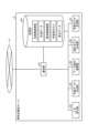
- FIG. 1 is a diagram showing a configuration example of an accident point locating system according to a first embodiment
- FIG. 1 is a diagram showing a configuration example of a fault point locating device according to a first embodiment
- FIG. 2 is a diagram showing a configuration example of an accident point locating server according to the first embodiment
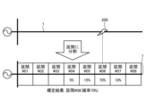
- FIG. 1 is a diagram showing an image of a location result when a machine learning classification method is used to locate an accident point according to the first embodiment
- FIG. 1 is a diagram showing an image of a location result when machine learning of a regression method is used to locate an accident point in the first embodiment
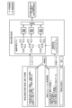
- FIG. 1 is a diagram showing an example of application of machine learning of a classification method to the fault point location system of the first embodiment.
- FIG. 1 is a diagram showing a configuration example of an accident point locating system according to a first embodiment
- FIG. 1 is a diagram showing a configuration example of a fault point locating device according to a first embodiment
- FIG. 2 is a diagram showing a configuration example of
- FIG. 1 is a sequence diagram showing an example of an accident point locating process in the accident point locating system according to the first embodiment.
- FIG. 1 is a diagram showing an overview of a correction process using “surrounding situation information of a grid” according to the first embodiment;
- FIG. 1 shows a first example of a display screen according to the first embodiment.
- FIG. 13 is a diagram showing a second example of the display screen of the first embodiment;
- FIG. 11 is a diagram showing a third example of the display screen of the first embodiment.
- FIG. 11 is a diagram showing a fourth example of the display screen of the first embodiment.
- FIG. 1 is a diagram showing an example of the configuration of a computer system that realizes an accident point locating device and an accident point locating server according to a first embodiment.
- FIG. 1 is a diagram showing a configuration example of a fault point locating system according to a second embodiment;
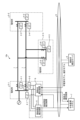
- FIG. 1 is a diagram showing a configuration example of an accident point locating system according to a first embodiment.
- the accident point locating system 10 according to the present embodiment locates an accident point in a power system.
- the power system to be the object of the accident point locating that is, the power system to be the object of the location of the accident point
- the power system to be the object of the location of the accident point includes electric power stations 2-1 to 2-3, which are power plants, substations, etc.
- the electric power station 2-1 and the electric power station 2-2 are connected by an electric wire 1, such as a transmission line or a distribution line.
- the electric wire 1 branched between the electric power station 2-1 and the electric power station 2-2 is connected to the electric power station 2-3.
- the electric power stations 2-1 to 2-3 are examples of one or more electric power stations 2, and the number of electric power stations 2 in the power system is not limited to the example shown in FIG. 1.
- Fig. 1 an example is shown in which the electric power stations 2 are connected by two electric wires 1, but the number of electric wires 1 connecting the electric power stations 2 is not limited to two.
- Fig. 1 is only an example, and the configuration of the electric power system that is the subject of fault point location is not limited to the example shown in Fig. 1.
- the electric power system that is the subject of fault point location will also be simply referred to as the electric power system.
- the electric power station 2-1 is provided with current transformers (CT) 3-1 and 3-2, which are an example of a current sensor that measures the current in the electric wire 1, and a voltage transformer (VT) 4-1, which is an example of a voltage sensor that measures the bus voltage of the electric power station 2-1.
- CT current transformers
- VT voltage transformer
- the electric power station 2-2 is provided with CTs 3-3 and 3-4, and a VT 4-2.
- the electric power station 2-3 is provided with CTs 3-5, 3-6, and a VT 4-3.
- CTs 3-1 to 3-6 are referred to without distinction, they will be referred to as CT3
- VTs 4-1 to 4-3 are referred to without distinction, they will be referred to as VT4.
- the accident point locating system 10 includes accident point locators 6-1 to 6-3 provided in the electric power stations 2-1 to 2-3, respectively, and an accident point locating server 8.
- accident point locators 6-1 to 6-3 may have the same configuration, and some of the accident point locators 6-1 to 6-3 may not have the function of performing the accident point locating process described below.
- the accident point locator 6 may be provided in all electric power stations 2 in the power system to be subjected to accident point locating, or the accident point locator 6 may be provided only in some of the electric power stations 2.
- the accident point locator 6 is capable of communicating with the accident point locating server 8 and the central monitoring system 7 via a communication network 9.
- the communication line between the accident point locator 6 and the accident point locator server 8, and the communication line between the accident point locator 6 and the central monitoring system 7 may be a wired line or a wireless line, or may be a mixture of wired and wireless lines.
- the accident point locating server 8 is an example of a learning device that generates a trained model for locating an accident point.
- the location processing execution device which is one of the accident point locating devices 6-1 to 6-3, locates an accident point using the trained model generated by the accident point locating server 8, corrects the location result of the accident point using correction information indicating the probability of the accident point determined according to the cause of the accident, and notifies the central monitoring system 7 of the corrected location result as the accident point location result.
- the accuracy of locating an accident point in a power system can be improved compared to a case where the cause of the accident is not considered.
- the accident point locating device 6-1 is the location processing execution device, but the location processing execution device may be the accident point locating device 6-2 or 6-3.
- the central monitoring system 7 is an EMS (Energy Management System) or a SCADA (Supervisory Control And Data Acquisition) system or a DAS (Distribution Automation System) that is installed in a central load dispatching center, a core system load dispatching control center, a local load dispatching control center, etc., and monitors and controls the power system.
- EMS Electronicgy Management System
- SCADA Supervisory Control And Data Acquisition
- DAS Distribution Automation System
- the power station 2-1 is further provided with an accident cause estimation device 5.
- the accident cause estimation device 5 is capable of communicating with a central monitoring system 7 via a communication network 9.
- the communication line between the accident cause estimation device 5 and the central monitoring system 7 may be a wired line or a wireless line, or a combination of wired and wireless lines.
- the accident cause estimation device 5 is also capable of communicating with an accident point locator 6.
- the communication line between the accident cause estimation device 5 and the accident point locator 6 may be a wired line or a wireless line, or a combination of wired and wireless lines.
- the accident cause estimation device 5 estimates the cause of the accident and transmits the estimation result to the central monitoring system 7 and the accident point locator 6 as the accident cause estimation result.
- the accident cause estimation device 5 acquires current and voltage from CTs 3-1, 3-2, VT 4-1, etc., performs clustering according to the cause of the accident based on the content rate of frequency components in the waveform data of the current or voltage in the power system when a past accident occurred, calculates the average value of each cluster and the probability value of each accident cause as cluster data, and when an accident occurs, estimates the cause of the accident using the content rate of frequency components in the waveform data acquired at the time of the accident and the cluster data.
- the method of estimating the cause of the accident in the accident cause estimation device 5 is not limited to this example, and any method may be used.
- the accident cause estimation device 5 is provided, but as described later, when an accident occurs, the cause of the accident may be estimated manually, in which case the accident cause estimation device 5 does not need to be provided. Also, in the example shown in FIG. 1, the accident cause estimation device 5 is provided in the electric power station 2-1, but the accident cause estimation device 5 may be provided outside the electric power station 2-1.
- the accident cause estimation device 5 may be integrated with the accident point locating device 6, or may be integrated with the accident point locating server 8. At least one of the accident cause estimation device 5 and the central monitoring system 7 may be included in the accident point locating system 10.
- the location processing execution device of the accident point locating device 6 locates the accident point using the trained model generated by the accident point locating server 8, and corrects the location result of the accident point using correction information indicating the probability of the accident point determined according to the cause of the accident.
- the correction information include the probability distribution of arc resistance by accident cause, the occurrence probability of accidents by type of surrounding conditions by accident cause, and the like.
- the accuracy of locating the accident point can be improved by considering the probability distribution of arc resistance according to the cause of the accident.
- the type of surrounding conditions includes, but is not limited to, at least one of forests, flat land, mountainous areas, coastal areas, urban areas, farmland, and the like.
- FIG. 2 is a diagram showing an example of the configuration of the accident point locating device 6-1 of this embodiment.
- the accident point locating device 6-1 includes a data acquisition unit 61, a location result inference unit 62, a memory unit 63, a communication unit 64, and a display data generation unit 65.
- FIG. 2 shows an example of the configuration of a location processing execution device, in which the accident point locating device 6-1 is the location processing execution device.
- the location processing execution device is not limited to this, and may be the accident point locating device 6-2 or the accident point locating device 6-3 as described above.
- the location processing execution device performs a data acquisition process for acquiring measurement data and an accident point locating process.
- the accident point locating devices 6 other than the location processing execution device do not need to perform the accident point locating process, and may be devices with the same configuration as the location processing execution device, or may be data acquisition devices that do not have the function of performing the accident point locating process.
- This data acquisition device has a configuration in which, for example, the location result inference unit 62 and the display data generation unit 65 have been removed from the accident point locator 6-1 shown in FIG. 2.
- the accident point locators 6 other than the location processing execution device may have the same configuration as the location processing execution device, and the accident point locator 6 that serves as the location processing execution device may be switchable. In the following, it is assumed that all the accident point locators 6 installed in each power station 2 have the same configuration.
- the data acquisition unit 61 acquires measurement data which is at least one of the current and voltage measured at the sub-electrical station 2 when a system accident occurs in the power system.
- the data acquisition unit 61 acquires, for example, at least the current and voltage measured at the sub-electrical station 2-1 when an accident occurs, but may acquire current and voltage at times other than when an accident occurs.
- the data acquisition unit 61 acquires "voltage (actual)” from VT4-1 installed at the sub-electrical station 2-1, acquires "current (actual)” from CTs 3-1 and 3-2 installed at the sub-electrical station 2-1, and stores “voltage (actual)” and "current (actual)” as measurement data in the memory unit 63.
- Voltage (actual) is a measurement value measured by VT4-1
- current (actual) is a measurement value measured by CTs 3-1 and 3-2.
- the data acquisition unit 61 also receives the “voltage (actual)” and “current (actual)” measured by the CT 3 and VT 4 at the electric power station 2 where the accident point locator 6 is installed from the accident point locators 6-2 and 6-3, which are other accident point locators 6.
- the data acquisition unit 61 stores the received "voltage (actual)” and "current (actual)” as measurement data in the memory unit 63 for each corresponding electric power station 2.
- the communication unit 64 transmits the measurement data ("voltage (actual)” and "current (actual)") stored in the memory unit 63 to the accident point locator 6-1.
- the communication unit 64 may also receive the "voltage (actual)” and “current (actual)” from the other accident point locators 6 and store them in the memory unit 63.
- the communication unit 64 and the data acquisition unit 61 can be considered as a data acquisition unit in a broad sense.
- the communication unit 64 communicates with external devices. For example, the communication unit 64 receives information such as system-related information (described later) and a learned model for locating an accident point from the accident point locating server 8, and stores the received information in the storage unit 63. The communication unit 64 also transmits the measurement data stored (saved) in the storage unit 63 to the accident point locating server 8. The communication unit 64 also transmits the accident point locating result (described later) output from the location result inference unit 62 to the central monitoring system 7. The communication unit 64 also receives the accident cause estimation result from the accident cause estimation device 5, and stores the received accident cause estimation result in the storage unit 63.
- information such as system-related information (described later) and a learned model for locating an accident point from the accident point locating server 8
- the communication unit 64 also transmits the measurement data stored (saved) in the storage unit 63 to the accident point locating server 8.
- the communication unit 64 also transmits the accident point locating result (described later) output from the location result inference
- the storage unit 63 stores system-related information, measurement data, accident cause estimation results, learned models, and calculation data.
- System-related information is information indicating the configuration, state, characteristics, etc. of the power system (hereinafter also referred to as the system), and includes, for example, "system topology” indicating the system configuration, “impedance information” indicating the impedance of the system, "surrounding situation information of the system,” and “statistical models.” Note that the storage unit 63 in the fault point locator 6-2, 6-3 does not need to store system-related information, learned models, accident cause estimation results, and calculation data.
- the “impedance information” is information indicating the impedance per unit length, for example, expressed in ⁇ /km.
- the "system topology” includes distance information indicating the distance from the substation 2 of each point in the system.
- the “impedance information” may be information indicating the impedance itself of each point in the system.
- the “system surrounding condition information” includes the type of surrounding conditions of each section (each position in the power system) described below, and a correction coefficient for each type of surrounding conditions by accident cause.
- the correction coefficient for each type of surrounding conditions by accident cause is information indicating the occurrence probability of an accident for each type of surrounding conditions by accident cause, and is an example of correction information.
- the "statistical model” is a probability distribution of arc resistance by accident cause, and is an example of correction information. Details of the "statistical model” will be described later.
- the measurement data includes the "voltage (actual)” and “current (actual)” acquired within the electric power station 2-1 by the data acquisition unit 61, and the “voltage (actual)” and “current (actual)” measured at the other electric power station 2 and received by the data acquisition unit 61 from the other accident point locating device 6.
- the measurement data is stored in the memory unit 63 in association with the electric power station 2 where the measurement was performed.
- the learned model is received from the accident point locating server 8 by the communication unit 64.
- the accident cause estimation result is received from the accident cause estimation device 5 by the communication unit 64.
- the accident cause estimation result may be input manually, in which case an input receiving unit (not shown) of the accident point locating device 6-1 may receive the input, or another device such as the accident point locating server 8 may receive the input, and the communication unit 64 may receive the accident cause estimation result from the other device.
- the calculated data is data calculated by the accident point locating device 6-1, and includes, for example, the "accident point (calculated value)" which is the inference result of the accident point calculated by the location result inference unit 62.
- the location result inference unit 62 obtains an inference result of the accident point by inputting features including the current and voltage acquired by the data acquisition unit 61 at the time of the occurrence of a system accident into the learned model, and corrects the inference result using the estimated result of the accident cause of the system accident and correction information indicating the probability of the accident point determined according to the accident cause.
- the location result inference unit 62 outputs the "accident point (calculated value)" obtained by locating the accident point to the communication unit 64 as the accident point location result.
- the location result inference unit 62 calculates "processed data” using the "voltage (actual)” and "current (actual)” at the time of the accident.
- the feature quantities are not limited to these, and may include at least one of the "voltage (actual)", “current (actual)” and “processed data” at the time of the accident. That is, the feature quantities may include at least one of at least a portion of the measurement data, which is at least one of the voltage and the current measured in the electric power station 2, and the processed data calculated from at least a portion of the measurement data.
- the feature quantities may be "current (actual)” and “processed data” obtained by processing the "voltage (actual)”.
- the location result inference unit 62 updates the "accident point (calculated value)" by correcting the "accident point (calculated value)", which is the inference result of the accident point obtained as an output from the learned model, using at least one of the "statistical model” and the "surrounding situation information of the system".
- the time of accident occurrence is not limited to the time when the accident occurred, but is, for example, a certain period including the estimated accident occurrence time, which is the time when it is determined that an abnormality due to the accident occurred, but is not limited to this.
- the accident point cannot be confirmed, and relocation (changing settings, recalculation, etc.) may be performed after a certain time has passed, such as one week after the accident, but such a case is also included in the time of accident point occurrence.
- the certain period (data acquisition period) at the time of accident occurrence when used as a feature value may be different from the acquisition period of measurement data at the time of accident occurrence used to calculate the arc resistance value described later.
- the acquisition period of data used as a feature value is, for example, a period from before to after the accident, and may be several cycles to several tens of cycles, or may be a period of one minute or more, and is not particularly limited.
- the display data generating unit 65 generates display data for displaying the location result of the accident point located by the location result inference unit 62 on the display screen. Specifically, the display data generating unit 65 generates display data indicating a display screen for displaying the "accident point (calculated value)" stored as calculation data in the storage unit 63, and outputs the generated display data to the display device 66. The display screen for displaying the "accident point (calculated value)" will be described later.
- the display device 66 displays the display screen based on the received display data. In FIG. 2, an example is shown in which the display device 66 is directly connected to the accident point locating device 6-1, but this is not limited thereto.
- the display data generating unit 65 may output the display data to the communication unit 64, and the communication unit 64 may transmit the display data to the display device 66.
- the display device 66 may be provided in the electric power station 2-1 or outside the electric power station 2-1.
- the display device 66 may be provided in the accident point locating device 6-1, in the accident point locating server 8, or as part of the central monitoring system 7. Also, in FIG. 2, an example is shown in which the display data generating unit 65 is provided in the accident point locating device 6-1, but the display data generating unit 65 may be provided in the central monitoring system 7, or the display data generating unit 65 may be provided in the accident point locating server 8.
- the display data generating unit 65 is provided in the accident point locating server 8, the "accident point (calculated value)" is transmitted from the accident point locating device 6-1 to the accident point locating server 8.
- FIG. 3 is a diagram showing an example of the configuration of the accident point locating server 8 of this embodiment.
- the accident point locating server 8 includes a communication unit 81, a storage unit 82, an input receiving unit 83, a learning data generating unit 84, an arc resistance calculating unit 85, a statistical model generating unit 86, and a learning model generating unit 87.
- the input reception unit 83 receives input from an operator, etc.
- the input reception unit 83 receives input of system-related information such as "system topology,” “impedance information,” and “system surrounding situation information,” and stores the input system-related information in the memory unit 82.
- system-related information such as "system topology,” “impedance information,” and "system surrounding situation information”
- the system-related information may be automatically input in cooperation with, for example, an external system present on the communication network 9, such as a database of an EMS, SCADA, DAS, or digital twin system.
- the input reception unit 83 receives input of accident-related information such as "accident point (record)” and “accident cause (record)” related to the accident, and stores the input accident-related information in the memory unit 82.
- accident-related information may be automatically input in cooperation with, for example, databases of external systems present on the communication network 9, such as EMS, SCADA, DAS, digital twin systems, accident management systems that manage accident information, and distribution facility maintenance systems.
- the "accident point (actual)” and “accident cause (actual)” are the accident point and accident cause that were actually confirmed by patrol after the accident occurred.
- the accident cause includes at least one of, for example, tree contact, bird and animal contact, metal contact, nesting material, lightning, snow, ice, wind and rain, etc., but the classification of accident causes is not limited to these and may be determined in any way.
- the communication unit 81 communicates with external devices. For example, the communication unit 81 transmits the "system topology,” “impedance information,” and “surrounding condition information of the system” from the system-related information stored in the memory unit 82 to the accident point locating device 6-1. The communication unit 81 also transmits the "statistical model” from the calculated data stored in the memory unit 82 to the accident point locating device 6-1. The communication unit 81 also transmits the learned model generated by the learning model generation unit 87 and stored in the memory unit 82 to the accident point locating device 6-1.
- the communication unit 81 also receives measurement data ("voltage (actual)” and "current (actual)” at the time of the accident) from the accident point locating device 6-1, and stores the received measurement data in the memory unit 82.
- the measurement data received by the communication unit 81 may be measurement data measured at the electric power station 2-1 corresponding to the fault point locator 6-1, or may be measurement data measured at the electric power stations 2-1 to 2-3 corresponding to the fault point locator 6-1 to 6-3, i.e., measurement data measured at multiple electric power stations 2.
- the memory unit 82 stores system-related information, measurement data, accident-related information, learned models, and calculation data.
- the system-related information stored in the memory unit 82 includes the "system topology,” “impedance information,” and “system surrounding situation information” received by the input receiving unit 83, and the “instantaneous value analysis model” (described later) generated by the learning data generating unit 84.
- the measurement data includes the "voltage (actual)” and “current (actual)” at the time of the accident, which are received from the accident point locating device 6-1 by the communication unit 81.
- the accident-related information includes the "accident point (actual)” and “accident cause (actual)” received by the input receiving unit 83, and the “arc resistance (calculated value)” (described later) calculated by the arc resistance calculation unit 85.
- the “voltage (actual)” and “current (actual)” are stored in correspondence with each accident, and the "accident point (actual)” and “accident cause (actual)” are stored in correspondence with each accident.
- information about the same accident may be associated with this information by adding the time of the accident or identification information of the accident, or the measurement data and accident-related information may be stored as a set for each accident, or the association may be made in other ways.
- the trained model is generated by the trained model generation unit 87 as described below.
- the calculated data includes the "current (calculated value)” and “voltage (calculated value)” calculated by a system simulation described below, and the "statistical model” generated by the statistical model generation unit 86 as described below.
- the arc resistance calculation unit 85 calculates an arc resistance value corresponding to each system accident that has already occurred in the power system, using the actual values of the measurement data ("current (actual)” and “voltage (actual)”), which are the current and voltage measured at the substation 2-1 when the accident occurred, the actual value of the accident point of the identified system accident ("accident point (actual)”), and system-related information.
- the arc resistance calculation unit 85 calculates an arc resistance value, which is the value of the arc resistance, using the "current (actual)”, “voltage (actual)”, and “accident point (actual)” for each accident corresponding to multiple past accidents stored in the storage unit 82, as well as the "system topology” and “impedance information”, and stores the calculated arc resistance value as the "arc resistance (calculated value)" in the storage unit 82 as accident-related information.
- the arc resistance calculation unit 85 calculates the impedance for each accident using the "current (actual)” and "voltage (actual)" at the time of the accident. If the calculated impedance is the first impedance, the first impedance is the original impedance up to the accident point plus the arc resistance (arc resistance due to the accident). The arc resistance calculation unit 85 calculates the second impedance using the "accident point (actual)", "system topology", and "impedance information". The second impedance is the original impedance, that is, the impedance from the electric power station 2-1 to the accident point, and the arc resistance calculation unit 85 calculates the arc resistance value by subtracting the second impedance from the first impedance.
- the arc resistance calculation unit 85 may calculate the current and voltage at the electric power station 2-1 by sequentially changing the arc resistance value at the "accident point (actual)” using the "system topology", “impedance information", and “accident point (actual)", and find the arc resistance value by searching for the arc resistance value at which the calculated current and voltage are closest to the "current (actual)” and "voltage (actual)”.
- the arc resistance calculation unit 85 performs a similar calculation to calculate the arc resistance value.
- the method for calculating the arc resistance value can be any general method, and is not limited to the above example.
- the ground resistance at the neutral point of the transformer may be taken into consideration.
- the arc resistance calculation unit 85 calculates the arc resistance (calculates the arc resistance value), but the arc resistance of each accident may be calculated by an external device or manually and input to the accident point location server 8, and the "arc resistance (calculated value)" corresponding to each accident may be stored in the memory unit 82 as accident-related information.
- the statistical model generating unit 86 generates a "statistical model” using the arc resistance value and the actual value of the accident cause corresponding to the arc resistance value ("accident cause (actual)") for multiple accidents. However, without being limited to this, the statistical model generating unit 86 may generate a "statistical model” using the “accident cause (estimated)” or may generate a “statistical model” using a mixture of the "accident cause (actual)” and the "accident cause (estimated)”.
- the arc resistance calculation unit 85 and the statistical model generation unit 86 may calculate the arc resistance value and the statistical model using the measurement data of one electric power station, i.e., the electric power station 2-1, or may calculate the arc resistance value and the statistical model using the measurement data of multiple electric power stations 2.
- the arc resistance calculation unit 85 calculates the arc resistance value using the measurement data of the other electric power stations 2 in a similar manner to when calculating the arc resistance value using the measurement data of the electric power station 2-1, which is the electric power station 2 at the power source end.
- the statistical model generation unit 86 may calculate statistical values (average value, median value, mode value, etc.) of the arc resistance values corresponding to the multiple electric power stations 2 for each accident, and generate the statistical model using the calculated statistical values.
- the statistical model generation unit 86 may generate the statistical model using all the calculated arc resistance values (regarding the arc resistance values calculated using the measurement data of multiple electric power stations 2 that actually correspond to the same accident as virtually different accidents).
- the arc resistance calculation unit 85 may use multiple equations to calculate the arc resistance value in the form of simultaneous equations and use the least squares method to find the solution.
- the method of calculating the arc resistance value and the statistical model using the measurement data of multiple electric power stations 2 is not limited to the above example, and any method may be used.
- EMTP Electro-Magnetic Transient Program
- XTAP eXpandable Transient Analysis Program
- PSCAD registered trademark
- the "accident point (setting)" is a value set as a condition in the instantaneous value analysis.
- machine learning classification
- machine learning of a classification method supervised machine learning of a classification method
- machine learning regression
- the machine learning algorithm may be a random forest, gradient boosting, neural network, support vector machine, or other algorithms.
- the trained model generated by the trained model generation unit 87 is transmitted to the accident point locator 6-1 as described above.
- the accident point locator 6-1 uses the trained model to locate the accident point.
- FIG. 4 is a diagram showing an image of a location result when machine learning classification method is used to locate the accident point of this embodiment.
- FIG. 5 is a diagram showing an image of a location result when machine learning regression method is used to locate the accident point of this embodiment.
- the occurrence point 200 indicates the location where the accident occurred.
- the accident point locator 6-1 can calculate the probability of each section into which the electric wire 1 is divided (probability of existence of an accident point in each section).
- the trained model generated using machine learning classification method is a trained model that can output information indicating the probability of existence of an accident point for each section in the system as an inference result of the accident point.
- the sections may be determined in any way, and may be divided so that the distance of the electric wire 1 is equal, may be determined taking into account equipment such as circuit breakers in the power system, or may be divided in other ways.
- the probability of each section is calculated, as shown in Figure 4, so that, for example, when working on-site to respond to an accident, it is possible to determine in which direction it is most efficient to search for the accident point from the section with the highest probability.
- FIG. 6 is a diagram showing an example of the application of machine learning of a classification method to the accident point locating system 10 of this embodiment.
- the dashed arrows indicate the flow of data in the learning process (learning phase)
- the solid arrows indicate the flow of data in the inference process (inference phase).
- the learning process is processed by the accident point locating server 8
- the inference process is processed by the accident point locating device 6-1.
- the "learning data" is generated using the analysis results of a system simulation such as instantaneous value analysis as described above.
- the method of generating the "learning data" is not limited to this, and if there is sufficient information about past accidents, actual values for each accident corresponding to multiple past accidents may be used, or both the actual values and the analysis results of the system simulation may be used.
- information about the accident to be located i.e., information obtained at the time of the accident
- the learned model to infer the accident point
- the accident point location result is obtained.
- FIG. 6 shows an example of the application of machine learning of a classification method, the probability of the existence of an accident point in each section is obtained as the accident point location result.
- FIG. 6 shows an example in which a random forest is used as the machine learning algorithm, but as described above, the machine learning algorithm is not limited to this. Also, as described above, in this embodiment, a correction is made to the accident point location result obtained as the output of the trained model.
- the accident point locating server 8 processes the learning process and the accident point locating device 6-1 processes the inference process
- the accident point locating device 6-1 may process both the learning process and the inference process. That is, the accident point locating device 6-1 may have the same components as the accident point locating server 8 and also have the function of a learning device.
- the accident point locating server 8 may also have a location result inference unit 62 and process both the learning process and the inference process.
- the communication unit 81 has the function of a data acquisition unit, and when an accident occurs, the communication unit 81 receives "current (actual)" and "voltage (actual)” from the power stations 2-1 to 2-3.
- a communication device installed in each of the power stations 2-1 to 2-3 may acquire the "current (actual)” and “voltage (actual)” from CT3 and VT4, and transmit the "current (actual)” and “voltage (actual)” to the fault point locating server 8, or CT3 and VT4 may each have a communication function and transmit the "current (actual)” and “voltage (actual)” to the fault point locating server 8, or the "current (actual)” and “voltage (actual)” may be transmitted to the fault point locating server 8 by other methods.
- FIG. 7 is a sequence diagram showing an example of the accident point locating process in the accident point locating system 10 of this embodiment.
- the accident point locating server 8 accepts input of system-related information (step S1) and stores the system-related information (step S2).
- the input receiving unit 83 accepts input of "system topology", “impedance information” and "surrounding situation information of the system”, and stores the input system-related information in the storage unit 82.
- the system-related information may be automatically input in cooperation with an external system present on the communication network 9, for example, a database of an EMS, SCADA, DAS, digital twin system, etc.
- the accident point locating server 8 transmits the system-related information to the accident point locating device 6-1 (step S3).
- the communication unit 81 transmits the "system topology,” “impedance information,” and “system surrounding situation information” stored in the memory unit 82 to the accident point locating device 6-1.
- the accident point locating device 6-1 stores the system-related information (step S4).
- the communication unit 64 receives the "system topology,” “impedance information,” and “system surrounding situation information” from the accident point locating server 8, and stores the received "system topology,” “impedance information,” and “system surrounding situation information” in the memory unit 63 as system-related information.
- the above steps S1 to S4 are pre-processing for setting the system conditions. Note that these processes are performed again if the system conditions change.
- the accident point locating server 8 acquires a "statistical model" for each cause of the accident (step S5). For example, the accident point locating server 8 calculates an arc resistance value using measurement data ("current (actual)” and “voltage (actual)") corresponding to past accidents, the "accident point (actual)", and system-related information. The accident point locating server 8 then acquires a "statistical model” by generating a “statistical model” showing the probability distribution of the arc resistance for each cause of the accident using the calculated arc resistance value and the "cause of accident (actual)”. It is assumed that the measurement data and accident-related information from past accidents are stored in the storage unit 82 by processing similar to steps S16 and S17 described later.
- step S5 an example of generating a "statistical model" showing the probability distribution of the arc resistance is described as the correction information, but as described above, "system surrounding situation information", that is, information showing the existence probability of an accident point according to the surrounding situation for each cause of the accident, may also be used as the correction information. Details of step S5 will be described later.
- the accident point locating server 8 generates "learned data” by system simulation (step S6). For example, the accident point locating server 8 performs system simulation under various conditions to calculate the "current (calculated value)” and “voltage (calculated value)” observed at each of the power stations 2-1 to 2-3 when an accident occurs, and generates “learned data” using the "current (calculated value)” and “voltage (calculated value)”.
- the accident point locating server 8 generates a trained model using the generated “learned data” (step S7).
- the accident point locating server 8 transmits the trained model and the "statistical model" to the accident point locating device 6-1 (step S8).
- the accident point locating device 6-1 stores the received trained model and the "statistical model” (step S9).
- the communication unit 64 receives the trained model and the "statistical model”, stores the trained model in the storage unit 63, and stores the "statistical model” in the storage unit 63 as system-related information.
- the timing of transmission of the trained model and the "statistical model” from the accident point location server 8 is not limited to the example shown in FIG. 7, and for example, the trained model and the "statistical model” may be transmitted at different times. For example, the trained model may be transmitted when the trained model is updated, and the "statistical model” may be transmitted when the statistical model is updated. Details of steps S6 to S9 will be described later.
- the above steps S6 to S9 are part of the learning process, which may be performed periodically, for example, once a month, when the "system topology” or the like changes, or at other times.
- the "statistical model” may be generated at a different time from the learning process because it is a process for correction, which will be described later.
- the "statistical model” may also be generated by the fault point locator 6-1.
- the fault point locator 6-1 is provided with an arc resistance calculator 85 and a statistical model generator 86, and generates the "statistical model", and stores the generated “statistical model” in the memory 63 as system-related information.
- the accident point locator 6-1 acquires measurement data at the time of the accident (step S11), and inputs features including the acquired measurement data into the trained model to obtain an inference result of the accident point (step S12).
- the accident point locator 6-1 may also acquire an estimation result of the cause of the accident in step S11, or may acquire an estimation result of the cause of the accident separately from step S11.
- the estimation result of the cause of the accident only needs to be acquired before the correction process.
- the measurement data acquired in step S11 includes the measurement data at the electric power station 2-1 and the measurement data at the electric power stations 2-2 and 2-3 received from the accident point locators 6-2 and 6-3.
- the accident point locator 6-1 performs a correction process on the inference result of the accident point (step S13), and transmits the corrected inference result of the accident point to the central monitoring system 7 as the accident point locator result (step S14).
- the correction process includes, for example, correction using a "statistical model” and processing using "surrounding situation information of the system.”
- the above steps S11 to S14 are part of the inference process. Details of steps S11 to S14 will be described later.
- the accident point locating device 6-1 transmits the measurement data (measurement data at the time of the accident occurrence) to the accident point locating server 8 (step S15).
- the accident point locating server 8 accepts the input of the accident-related information (step S16) and stores the measurement data and the accident-related information in association with each other (step S17).
- the accident-related information may be automatically input in cooperation with an external system present on the communication network 9, such as an EMS, SCADA, DAS, digital twin system, an accident management system that manages accident information, or a database such as a maintenance system for distribution facilities.
- Steps S15 to S17 are processes for storing the measurement data and accident-related information at the time of past accidents that the accident point locating server 8 uses to generate the "statistical model" in the storage unit 82.
- steps S15 to S17 are performed after the occurrence of an accident, but steps S15 to S17 do not have to be performed for each accident. Since the learning process does not need to be performed frequently, the "current (actual)” and “voltage (actual)” related to past accidents do not need to be acquired frequently. For example, the "current (actual)” and “voltage (actual)” for a certain period of time may be transmitted in bulk from the accident point locating device 6-1 to the accident point locating server 8 and stored in the memory unit 82.
- the accident point locating device 6-1 also performs a display process (step S18). Specifically, for example, the display data generating unit 65 generates display data showing a display screen that displays the accident point locating result, i.e., the "accident point (calculated value)," and outputs the generated display data to the display device 66. Note that step S18 does not have to be performed. Also, as described above, the display data may be generated by the accident point locating server 8.
- FIG. 8 is a flow chart showing an example of the process of acquiring the "statistical model” in this embodiment.
- the accident point location server 8 calculates and stores the "arc resistance (calculated value)" using the "measurement data (actual)”, “accident point (actual)", “system topology” and “impedance information” at the time of the accident (step S21).
- the arc resistance calculation unit 85 calculates the arc resistance value using the "current (actual)”, “voltage (actual)”, and “accident point (actual)” for each accident corresponding to multiple past accidents stored in the storage unit 82, the "system topology” and the “impedance information”, and stores the calculated arc resistance value as the "arc resistance (calculated value)" in the storage unit 82 as accident-related information.
- the accident point location server 8 generates and stores a "statistical model” from the “accident cause (actual)” and the “arc resistance (calculated value)” (step S22).
- the statistical model generation unit 86 generates a "statistical model” showing the probability distribution of the arc resistance for each accident cause using the "accident cause (actual)” and “arc resistance (calculated value)” stored in the storage unit 82, and stores the "statistical model” as calculated data in the storage unit 82.
- the statistical model generation unit 86 may generate a "statistical model” using the "accident cause (estimated)", or may generate a “statistical model” using a mixture of the "accident cause (actual)” and the “accident cause (estimated)".
- Specific examples of the "statistical model” include a histogram, or a probability density function, a probability distribution function, a cumulative distribution function, etc. obtained from the histogram using a parametric method or a non-parametric method.
- An example of a parametric method is the least squares method, and an example of a non-parametric method is the kernel density estimation method, but the method used to generate the "statistical model” can be any method and is not limited to these.
- FIG. 9 is a flowchart showing an example of the "learned data” generation process and the learned model generation process of this embodiment.
- the fault point location server 8 uses the "system topology” and “impedance information” to generate and store an "instantaneous value analysis model" of the power system (step S31).
- the learning data generation unit 84 uses the "system topology" and “impedance information" stored in the storage unit 82 to generate an "instantaneous value analysis model" of the power system for performing instantaneous value analysis, which is an example of a system simulation, and stores it in the storage unit 82 as system-related information.
- the system simulation is not limited to instantaneous value analysis.
- the accident point location server 8 calculates "processed data” using the “current (calculated value)” and “voltage (calculated value)” (calculated current and voltage), associates the instantaneous value analysis conditions (accident point) with the "current (calculated value)", “voltage (calculated value)", and “processed data”, and stores them as “learned data” (step S34).
- the learning data generation unit 84 calculates "processed data” using the calculated “current (calculated value)” and “voltage (calculated value)”, sets the “current (calculated value)”, “voltage (calculated value)”, and “processed data” with the conditions (accident point) as “learned data”, and stores the "learned data” in the memory unit 82 as calculated data.
- the accident point location server 8 performs machine learning using the "learning data” in which the "current (calculated value)”, “voltage (calculated value)", and “processed data” are the feature quantities and the corresponding "accident point (setting)” is the answer, and generates and stores a learned model (step S35).
- the feature quantities are not limited to this, and may include at least one of the "voltage (calculated value)", “current (calculated value)", and “processed data” at the time of the accident, for example.
- the feature quantity may be only the “voltage (calculated value)", only the “current (calculated value)”, only the “processed data”, or two of the “voltage (calculated value)", “current (calculated value)", and “processed data”.
- the learning model generation unit 87 performs supervised machine learning using multiple sets of "learning data” in which the "current (calculated value)", “voltage (calculated value)", and “processed data” stored in the storage unit 82 are the feature quantities and the "accident point (setting)” is the answer (correct answer), to generate a learned model, and stores the generated learned model in the storage unit 82.
- the accident point locating server 8 transmits the trained model to the accident point locating device 6-1 (step S36).
- the communication unit 81 transmits the trained model stored in the storage unit 82 to the accident point locating device 6-1.
- the accident point locating device 6-1 receives the trained model, it stores the trained model in the storage unit 63.
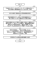
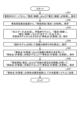
- FIG. 10 is a flow chart showing an example of the inference process in this embodiment.
- the fault point locator 6-1 acquires and stores "current (actual)” and “voltage (actual)” from CT3 and VT4 of the power stations 2-1 to 2-3 (step S41).
- the data acquisition unit 61 acquires the measurement values by CT3-1, 3-2 and VT4-1 at the time of the accident from CT3-1, 3-2 and VT4-1 and stores them as measurement data in the memory unit 63, and also receives "current (actual)” and “voltage (actual)” from the fault point locators 6-2 and 6-3, respectively, and stores them as measurement data in the memory unit 63.
- the accident point locator 6-1 acquires and stores the "accident cause (estimated)" from the accident cause estimator 5 (step S42).
- the communication unit 64 receives the accident cause estimation result ("accident cause (estimated)") from the accident cause estimator 5, and stores the received accident cause estimation result in the storage unit 63.
- the accident cause estimation result is not limited to being received from the accident cause estimator 5, but may be input to the accident point locator 6-1, or may be input to a device other than the accident point locator 6-1 and transmitted from that device to the accident point locator 6-1.
- the accident point locating device 6-1 generates "processed data”, inputs the “current (actual)”, “voltage (actual)”, and “processed data” to the trained model, and stores the “accident point (calculated value)” output from the trained model (step S43).
- the location result inference unit 62 generates “processed data” using the “voltage (actual)” and “current (actual)” at the time of the accident stored as measurement data in the memory unit 63.
- the location result inference unit 62 then inputs the "current (actual)”, “voltage (actual)”, and “processed data” as feature quantities into the trained model stored in the memory unit 63, and stores the "accident point (calculated value)", which is the output of the trained model, in the memory unit 63 as calculated data.
- the accident point locator 6-1 calculates and stores the probability distribution of distance using the "statistical model” (step S44).
- the location result inference unit 62 uses the "statistical model” and the “accident cause (estimate)” to determine the probability distribution of arc resistance corresponding to the "accident cause (estimate)", converts the probability distribution of arc resistance into a probability distribution of distance using the "system topology” and “impedance information”, and stores the converted probability distribution of distance in the memory unit 63 as calculated data.
- the accident point locating device 6-1 corrects the "accident point (calculated value)" using the “accident point (calculated value)” and the probability distribution of the distance, thereby updating and saving the “accident point (calculated value)” (step S45).
- the location result inference unit 62 shifts the "accident point (calculated value)" stored in the memory unit 63 using the probability distribution of the distance stored in the memory unit 63.
- the location result inference unit 62 multiplies the "accident point (calculated value)" by the probability corresponding to the distance of each point, performs processing to shift the "accident point (calculated value)" by the distance of each point, and adds up the processing results for m points to shift the "accident point (calculated value)" using the probability distribution of the distance.
- the accident point locating device 6-1 corrects the "accident point (calculated value)" using the “accident cause (estimated)” and “system surrounding situation information” to update and store the “accident point (calculated value)” (step S46).
- the location result inference unit 62 corrects the "accident point (calculated value)” using the “accident cause (estimated)” and “system surrounding situation information” stored in the memory unit 63, updates the "accident point (calculated value)” stored in the memory unit 63 to the corrected “accident point (calculated value)", and stores the corrected "accident point (calculated value)” in the memory unit 63.
- the "system surrounding condition information” includes, for example, the type of surrounding condition for each section and a correction coefficient for each type of surrounding condition for each accident cause.
- FIG. 11 is a diagram showing an overview of the correction process using the "system surrounding condition information" of this embodiment.
- the surrounding conditions of sections #01 to #03 and #09 to #14 correspond to flat land
- the surrounding conditions of sections #04 to #08 correspond to forest.
- the "accident cause (estimated)" is tree contact
- the correction coefficient corresponding to tree contact is 1 for flat land and 3 for forest.
- FIG. 11 shows an example in which machine learning of a classification method is used as machine learning, and the "accident point (calculated value)" is the existence probability of an accident point in each section.
- the "fault point (calculated value)" obtained by the processing of step S43 is 2.5% for section #04, 7.5% for section #05, 35% for section #06, 5% for section #07, 2.5% for section #10, 7.5% for section #11, 35% for section #12, and 5% for section #13.
- the multiple branched areas become equivalent in terms of electrical calculations, so there is a possibility that the location result of the fault point will be two areas like this.
- the location result inference unit 62 multiplies the probability of each section by a correction coefficient corresponding to the type of surrounding conditions of each section, which differs for each accident cause.
- FIG. 11 shows an example in which the cause of the accident is estimated to be contact with a tree.
- the location result inference unit 62 multiplies the correction coefficient 3 by 2.5, which is the value obtained as the "accident point (calculated value)", to obtain a calculation result of 7.5.
- section #10 is flat land
- the location result inference unit 62 multiplies the correction coefficient 1 by 2.5, which is the value obtained as the "accident point (calculated value)", to obtain a calculation result of 2.5.
- the location result inference unit 62 performs similar calculations for each section to obtain calculation results, and then standardizes the total value of the calculation results (200 in the example shown in FIG. 11) so that the total becomes 100.
- the total value of the probability of the existence of an accident point at all points can be set to 100%.
- This normalization is not essential, and is a process performed to make the location results easier to see, so it does not have to be performed, and the value obtained by multiplying the probability of each section by the correction coefficient may be used as the "accident point (calculated value)" after correction. Note that the number of sections, types of surrounding conditions, and values of correction coefficients shown in FIG.
- the number of sections, types of surrounding conditions, and values of correction coefficients are not limited to the example shown in FIG. 11.
- the value of the correction coefficient (for example, in the case of contact with a tree, the correction coefficient for forest is set to 3 and the correction coefficient for flat land is set to 1) may be determined for each system, or may be determined by weighting each section.
- the same correction coefficient may be used for each system and each accident type. In this way, by performing correction according to the type of surrounding conditions, the location accuracy of the accident point can be improved compared to the case where correction is not performed.
- the "system surrounding situation information" is input to the accident point locating server 8, but this is not limited thereto.
- the accident point locating server 8 may calculate the "system surrounding situation information” using the "accident point (record)” and “accident cause (record)” related to past accidents and the type of surrounding situation for each section.
- machine learning is used to calculate the "system surrounding situation information", but this is not limited thereto.
- the information may be set by a person based on experience, etc.
- the accident point locator 6-1 transmits the "accident point (calculated value)" to the central monitoring system 7 as the accident point locating result (step S47).
- the communication unit 64 transmits the "accident point (calculated value)" stored in the memory unit 63 to the central monitoring system 7 as the accident point locating result.
- FIG. 12 is a diagram showing a first example of a display screen of this embodiment.
- "accident point (calculated value)" is displayed in a list format indicating the probability of existence of an accident point for each section.
- the display data generating unit 65 may generate display data for displaying a display screen indicating the probability of existence of an accident point for each section in a list format as shown in FIG. 12.
- FIG. 13 is a diagram showing a second example of the display screen of this embodiment.
- the "accident point (calculated value)" is shown on the system diagram.
- the probability corresponding to each section is shown at a position (for example, the position of the representative point of each section) of the "accident point (calculated value)" on the system diagram corresponding to each section.
- the representative point may be the center of each section, the start point of each section (the end on the side of the electric power station 2-1), the end point of each section (the end on the opposite side from the electric power station 2-1), or a position other than these.
- the display data generating unit 65 may generate display data for displaying a display screen showing the "accident point (calculated value)" on the system diagram as shown in FIG. 13.
- FIG. 14 is a diagram showing a third example of the display screen of this embodiment.
- the "accident point (calculated value)" is displayed on the system diagram as in the example shown in FIG. 13, but the figure displayed at the corresponding point in the power system is changed according to the numerical value corresponding to the "accident point (calculated value)".
- the probability is divided into levels, such as 10% or less, more than 10% to 20% or less, more than 20% to 30% or less, etc., and the figure corresponding to each numerical value is displayed so that the figure becomes larger as the level corresponding to the higher probability. In other words, the figure is displayed in a different manner for each level.
- the definition of the level division and the figure corresponding to each level are not limited to this example.
- a figure of a different color may be displayed for each level.
- the numerical value corresponding to the "accident point (calculated value)" itself may be displayed so that the figure becomes larger as the level corresponding to the higher probability, or may be displayed in a different color for each level.
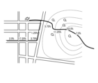
- FIG. 15 is a diagram showing a fourth example of the display screen of this embodiment.
- the "accident point (calculated value)" is shown on a map.
- the probability corresponding to each section is shown at a geographical position corresponding to the representative point of each section of the "accident point (calculated value)" on the map.
- the representative point may be the center of each section, the start point of each section, or the end point of each section, or may be other than these.
- the display data generating unit 65 may include information (map information) indicating the geographical arrangement of each electric wire 1 in the "system topology”, calculate the geographical position of the representative point in the system diagram using the information indicating the geographical arrangement of each electric wire 1, and generate display data for displaying a display screen showing the "accident point (calculated value)" on a map as shown in FIG. 15. Note that when the "accident point (calculated value)" is shown on a map, the probability may be divided into levels, and the levels may be displayed in different shapes or colors, as in the example shown in FIG. 14.
- the display data generation unit 65 may generate two or more display screens (individual display screens) from the first, second, third, and fourth examples, and generate display data such that the generated two or more individual display screens are displayed simultaneously. Furthermore, the generated two or more individual display screens may be displayed sequentially by switching.
- the control unit 101 is a processor such as a CPU (Central Processing Unit), and executes a program that describes the processing in the accident point locating device 6-1 or the accident point locating server 8 of this embodiment.
- the input unit 102 is composed of, for example, a keyboard, a mouse, etc., and is used by the user of the computer system to input various information.
- the storage unit 103 includes various memories such as a RAM (Random Access Memory) and a ROM (Read Only Memory) and a storage device such as a hard disk, and stores the programs to be executed by the control unit 101, necessary data obtained in the process of processing, etc.
- the storage unit 103 is also used as a temporary storage area for programs.
- the display unit 104 is composed of a display, an LCD (liquid crystal display panel), etc., and displays various screens to the user of the computer system.
- the communication unit 105 is a receiver and a transmitter that perform communication processing.
- the output unit 106 is a printer, etc. Note that FIG. 16 is an example, and the configuration of the computer system is not limited to the example of FIG. 16. For example, the computer system that realizes the accident point locator 6-1 does not need to include the display unit 104 and the output unit 106.
- the program is installed in an auxiliary storage device that is part of the storage unit 103 from a CD-ROM or DVD-ROM set in a CD (Compact Disc)-ROM drive or DVD (Digital Versatile Disc)-ROM drive (not shown). Then, when the program is executed, the program read from the auxiliary storage device of the storage unit 103 is stored in the main storage area of the storage unit 103. In this state, the control unit 101 executes processing as the accident point locating device 6-1 or accident point locating server 8 of this embodiment according to the program stored in the storage unit 103.
- a CD-ROM or DVD-ROM is used as a recording medium to provide a program describing the processing in each of the accident point locating device 6-1 and the accident point locating server 8, but this is not limiting.
- a program provided by a transmission medium such as the Internet via the communication unit 105 may be used.
- the location result inference unit 62 and display data generation unit 65 shown in FIG. 2 are realized by the control unit 101 shown in FIG. 16 executing a program stored in the storage unit 103 shown in FIG. 16.
- the storage unit 103 is also used to realize the location result inference unit 62 and the display data generation unit 65.
- the storage unit 63 shown in FIG. 2 is part of the storage unit 103 shown in FIG. 16.
- the data acquisition unit 61 and communication unit 64 shown in FIG. 2 are realized by the communication unit 105 and control unit 101 shown in FIG. 16.
- the accident point locator 6-1 may be realized by multiple computer systems.
- the accident point locators 6-2 and 6-3 are similarly realized by computer systems.
- the learning data generating unit 84, the arc resistance calculating unit 85, the statistical model generating unit 86, and the learning model generating unit 87 shown in FIG. 3 are realized by executing the program stored in the memory unit 103 shown in FIG. 16 by the control unit 101 shown in FIG. 16.
- the memory unit 103 is also used to realize the learning data generating unit 84, the arc resistance calculating unit 85, the statistical model generating unit 86, and the learning model generating unit 87.
- the memory unit 82 shown in FIG. 3 is a part of the memory unit 103 shown in FIG. 16.
- the communication unit 81 shown in FIG. 3 is realized by the communication unit 105 and the control unit 101 shown in FIG. 16.
- the input receiving unit 83 shown in FIG. 3 is realized by the input unit 102 shown in FIG. 16.
- the accident point locating server 8 may be realized by a plurality of computer systems.
- the accident point locating server 8 may be realized by, for example, a cloud system.
- the program of this embodiment causes a computer system to execute, for example, a data acquisition step of acquiring measurement data, which is at least one of the current and voltage measured at the power station 2 when a system accident occurs in the power system, and a location step of acquiring an inference result of the accident point by inputting a feature value including at least one of at least a portion of the measurement data acquired at the time of the system accident and at least one of the processed data calculated from at least a portion of the measurement data acquired by the data acquisition step into a trained model generated by machine learning for inferring the accident point from a feature value including at least a portion of the measurement data measured at the power station 2 and at least one of the processed data calculated from at least a portion of the measurement data, and correcting the inference result using an estimated result of the cause of the system accident and correction information indicating the probability of the accident point determined according to the cause of the accident.
- the accident point locator 6-1 corrects the inference result obtained by inputting features into the trained model generated using training data generated by performing a system simulation, using information indicating the probability of the accident point according to the cause of the accident. This improves the accuracy of locating the accident point in the power system compared to when the cause of the accident is not considered. For example, when the accident point locator 6-1 performs correction using a "statistical model" of the arc resistance value, it can locate the accident point reflecting the difference in the arc resistance value for each accident cause. Also, for example, when the accident point locator 6-1 performs correction using "system surrounding situation information", it can locate the accident point reflecting the occurrence probability of each accident factor according to the surrounding situation. Also, when machine learning, a classification method, is used, the distribution of the existence probability of the accident point can be known, so that the search for the accident point can be performed efficiently.
- the measurement data of the existing CT3 and VT4 installed at the substations 2-1 to 2-3 can be used, there is no need to install a sensor on the overhead ground wire, which helps reduce costs. Furthermore, if a sensor is installed on the overhead ground wire and measurement data is used, in the event of a short circuit accident, no current flows through the overhead ground wire, and in the case of a distribution line, an overhead ground wire does not exist, so a sensor cannot be installed on the overhead ground wire. In this embodiment, since there is no need to use a sensor installed on the overhead ground wire, it can also be applied when a short circuit accident occurs or when an overhead ground wire does not exist.
- Embodiment 2. 17 is a diagram showing a configuration example of an accident point locating system according to a second embodiment.
- An accident point locating system 10a according to this embodiment includes an accident point locating server 8 and an accident point locating device 6-1 provided in a power station 2-1.
- Components having the same functions as those in the first embodiment are given the same reference numerals as those in the first embodiment, and duplicated explanations are omitted. Below, differences from the first embodiment will be mainly explained.
- the configuration of the accident point locator 6-1 is the same as that of the first embodiment.
- the accident point locators 6-2 and 6-3 described in the first embodiment are not used, that is, there is only one accident point locator 6, so the accident point locator 6-1 does not receive measurement data from other accident point locators 6, and only the measurement data measured at the power station 2-1 is stored in the memory unit 63 as the measurement data.
- the accident point locator server 8 calculates the current and voltage corresponding to the power station 2-1 by instantaneous value analysis in step S33.
- step S34 the accident point locator server 8 calculates "processed data” using the calculated current and voltage ("current (calculated value)” and “voltage (calculated value)”), and generates “learning data” with “current (calculated value)”, “voltage (calculated value)", and “processed data” as features and “accident point (setting)” as the answer.
- the inference process may be performed by the accident point locator 6-1 or by the accident point locator server 8.
- the accident point locator 6-1 may also perform the learning process in addition to the inference process.
- the "system model” may also be generated by the accident point locator 6-1.
- the current and voltage used as the feature may be the current and voltage measured at one electric power station 2. That is, the measurement data used as the feature may be the current and voltage measured at each of the multiple electric power stations 2 as described in embodiment 1, or the current and voltage measured at one electric power station 2 as described in this embodiment.
- the feature is not limited to an example including both current and voltage, but may include at least one of current, voltage, and processed data. This embodiment can also achieve the same effect as embodiment 1.
- the location accuracy of the fault point may be inferior to embodiment 1, but the system configuration can be simplified compared to embodiment 1.
Landscapes
- Physics & Mathematics (AREA)
- General Physics & Mathematics (AREA)
- Locating Faults (AREA)
Abstract
本開示にかかる事故点標定装置(6-1)は、電力系統における系統事故の発生時に電気所で計測された電流および電圧のうちの少なくとも一方である計測データを取得するデータ取得部(61)と、電気所で計測される計測データの少なくとも一部と当該計測データの少なくとも一部から算出される加工データとのうちの少なくとも一方を含む特徴量から事故点を推論するための機械学習により生成された学習済モデルに、データ取得部(61)によって系統事故の発生時に取得された計測データの少なくとも一部と当該計測データの少なくとも一部から算出される加工データとのうちの少なくとも一方を含む特徴量を入力することによって事故点の推論結果を取得し、推論結果を系統事故の事故原因の推定結果と事故原因に応じて定まる事故点の確率を示す補正情報とを用いて補正する標定結果推論部(62)と、を備える。
Description
本開示は、電力系統における事故点の標定を行う事故点標定装置、学習装置、事故点標定システム、事故点標定方法およびプログラムに関する。
送電系統、配電系統などの電力系統において、短絡、地絡などの異常状態(以下、系統事故または事故と呼ぶ)が発生すると、事故からの復旧作業のために、事故が発生した箇所である事故点を標定することが望まれる。
特許文献1には、複数の鉄塔ごとに架空地線に流れる電流を計測する電流センサを設け、電流センサによって取得された故障時の電流情報を用いてニューラルネットワーク手法により送電線の事故区間を標定する事故区間標定方法が開示されている。
電力系統における事故が発生した場合、事故原因により電流への影響が異なると考えられる。特許文献1に記載の事故区間標定方法では事故原因が考慮されていないため、標定精度が低い可能性がある。
本開示は、上記に鑑みてなされたものであって、電力系統における事故点の標定精度を向上させることができる事故点標定装置を得ることを目的とする。
上述した課題を解決し、目的を達成するために、本開示にかかる事故点標定装置は、電力系統における系統事故の発生時に電気所で計測された電流および電圧のうちの少なくとも一方である計測データを取得するデータ取得部と、電気所で計測される計測データの少なくとも一部と当該計測データの少なくとも一部から算出される加工データとのうちの少なくとも一方を含む特徴量から事故点を推論するための機械学習により生成された学習済モデルに、データ取得部によって系統事故の発生時に取得された計測データの少なくとも一部と当該計測データの少なくとも一部から算出される加工データとのうちの少なくとも一方を含む特徴量を入力することによって事故点の推論結果を取得し、推論結果を系統事故の事故原因の推定結果と事故原因に応じて定まる事故点の確率を示す補正情報とを用いて補正する標定結果推論部と、を備える。
本開示にかかる事故点標定装置は、電力系統における事故点の標定精度を向上させることができるという効果を奏する。
以下に、実施の形態にかかる事故点標定装置、学習装置、事故点標定システム、事故点標定方法およびプログラムを図面に基づいて詳細に説明する。
実施の形態1.
図1は、実施の形態1にかかる事故点標定システムの構成例を示す図である。本実施の形態の事故点標定システム10は、電力系統における事故点を標定する。図1では、事故点標定対象の電力系統、すなわち事故点の標定対象となる電力系統も簡略化して図示している。図1に示した例では、事故点の標定対象となる電力系統は、発電所、変電所などである電気所2-1~2-3を含む。図1では、電気所2-1と電気所2-2とは、送電線、配電線などの電線1で接続されている。また、電気所2-1と電気所2-2との間で分岐した電線1が電気所2-3に接続されている。以下、電気所2-1~2-3を個別に区別せずに示すときには、電気所2と記載する。電気所2-1~2-3は、1つ以上の電気所2の一例であり、電力系統における電気所2の数は図1に示した例に限定されない。図1では、電気所2間が2本の電線1で接続される例を示しているが、電気所2間を接続する電線1の数は2本に限定されない。また、図1は一例であり、事故点の標定対象となる電力系統の構成は図1に示した例に限定されない。以下、事故点の標定対象となる電力系統を、単に電力系統とも記載する。
図1は、実施の形態1にかかる事故点標定システムの構成例を示す図である。本実施の形態の事故点標定システム10は、電力系統における事故点を標定する。図1では、事故点標定対象の電力系統、すなわち事故点の標定対象となる電力系統も簡略化して図示している。図1に示した例では、事故点の標定対象となる電力系統は、発電所、変電所などである電気所2-1~2-3を含む。図1では、電気所2-1と電気所2-2とは、送電線、配電線などの電線1で接続されている。また、電気所2-1と電気所2-2との間で分岐した電線1が電気所2-3に接続されている。以下、電気所2-1~2-3を個別に区別せずに示すときには、電気所2と記載する。電気所2-1~2-3は、1つ以上の電気所2の一例であり、電力系統における電気所2の数は図1に示した例に限定されない。図1では、電気所2間が2本の電線1で接続される例を示しているが、電気所2間を接続する電線1の数は2本に限定されない。また、図1は一例であり、事故点の標定対象となる電力系統の構成は図1に示した例に限定されない。以下、事故点の標定対象となる電力系統を、単に電力系統とも記載する。
電気所2-1には、電線1の電流を計測する電流センサの一例である変流器(CT:Current Transformer)3-1,3-2と、電気所2-1の母線電圧を計測する電圧センサの一例である計器用変圧器(VT:Voltage Transformer)4-1とが設けられている。同様に、電気所2-2には、CT3-3,3-4と、VT4-2とが設けられている。電気所2-3には、CT3-5,3-6と、VT4-3とが設けられている。以下、CT3-1~3-6を個別に区別せずに示すときには、CT3と記載し、VT4-1~4-3を個別に区別せずに示すときには、VT4と記載する。
事故点標定システム10は、電気所2-1~2-3にそれぞれ設けられた事故点標定装置6-1~6-3と、事故点標定サーバ8とを備える。以下、事故点標定装置6-1~6-3のそれぞれを個別に区別せずに示すときには、事故点標定装置6と記載する。事故点標定装置6-1~6-3は同一の構成であってもよいし、事故点標定装置6-1~6-3のうち一部は、後述する事故点標定処理を実施する機能を備えていなくてもよい。また、事故点標定対象の電力系統における全ての電気所2に事故点標定装置6が設けられてもよいし一部の電気所2のみに事故点標定装置6が設けられてもよい。事故点標定装置6は、通信ネットワーク9を介して事故点標定サーバ8および中央監視システム7とそれぞれ通信を行うことが可能である。事故点標定装置6と事故点標定サーバ8との間の通信回線、および事故点標定装置6と中央監視システム7との間の通信回線は、有線回線であっても無線回線であってもよく、有線回線と無線回線とが混在していてもよい。
事故点標定サーバ8は、事故点を標定するための学習済モデルを生成する学習装置の一例である。事故点標定装置6-1~6-3のうちの1つである標定処理実行装置は、事故点標定サーバ8によって生成された学習済モデルを用いて事故点を標定し、事故点の標定結果を、事故原因に応じて定まる事故点の確率を示す補正情報を用いて補正し、補正した標定結果を事故点標定結果として中央監視システム7へ通知する。これにより、本実施の形態では、事故原因を考慮しない場合に比べて、電力系統における事故点の標定精度を向上させることができる。図1に示した例では、事故点標定装置6-1が標定処理実行装置であるが、標定処理実行装置は事故点標定装置6-2または6-3であってもよい。
中央監視システム7は、中央給電指令所、基幹系統給電制御所、地方給電制御所などに設置されるEMS(Energy Management System:エネルギーマネージメントシステム)、あるいは、SCADA(Supervisory Control And Data Acquisition:監視制御システム)などのシステム、あるいは、DAS(Distribution Automation System:配電自動化システム)などであり、電力系統の監視や制御などを行う。
図1に示した例では、電気所2-1には、さらに、事故原因推定装置5が設けられている。事故原因推定装置5は、通信ネットワーク9を介して中央監視システム7と通信を行うことが可能である。事故原因推定装置5と中央監視システム7との間の通信回線は、有線回線であっても無線回線であってもよく、有線回線と無線回線とが混在していてもよい。また、事故原因推定装置5は、事故点標定装置6と通信を行うことが可能である。事故原因推定装置5と事故点標定装置6との間の通信回線は、有線回線であっても無線回線であってもよく、有線回線と無線回線とが混在していてもよい。
事故原因推定装置5は、事故が発生した場合に、事故原因を推定し、推定結果を事故原因推定結果として中央監視システム7および事故点標定装置6へ送信する。例えば、事故原因推定装置5は、CT3-1,3-2およびVT4-1などから電流および電圧を取得し、過去の事故発生時における電力系統における電流または電圧の波形データの周波数成分の含有率に基づいて事故原因に応じたクラスタリングを行い各クラスタの平均値と各事故原因の確率値とをクラスタデータとして算出しておき、事故が発生した際には、事故発生時に取得された波形データの周波数成分の含有率とクラスタデータとを用いて、事故原因を推定する。事故原因推定装置5における事故原因の推定方法は、この例に限定されず、どのような方法であってもよい。
なお、図1では、事故原因推定装置5が設けられる例を説明するが、後述するように、事故が発生した際の事故原因の推定は人手で行われてもよく、この場合には、事故原因推定装置5が設けられなくてよい。また、図1に示した例では、事故原因推定装置5は、電気所2-1に設けられているが、事故原因推定装置5は、電気所2-1外に設けられていてもよい。
また、事故原因推定装置5は、事故点標定装置6と一体化されていてもよいし、事故点標定サーバ8と一体化されていてもよい。また、事故原因推定装置5および中央監視システム7のうちの少なくとも一方を、事故点標定システム10に含めてもよい。
上述したように、本実施の形態では、事故点標定装置6のうちの標定処理実行装置は、事故点標定サーバ8によって生成された学習済モデルを用いて事故点を標定し、事故点の標定結果を、事故原因に応じて定まる事故点の確率を示す補正情報を用いて補正する。補正情報としては、例えば、事故原因別のアーク抵抗の確率分布、事故原因別の周辺状況の種別ごとの事故の発生確率、などを例示できる。例えば、事故原因によりアーク抵抗の値が異なると考えられるため、事故原因に応じたアーク抵抗の確率分布を考慮することで事故点の標定精度を向上させることができる。また、電線1の周辺状況の種別により発生しやすい事故原因があると考えられる。例えば、森林では平地に比べて樹木接触が起こりやすい。このため、「事故原因(推定)」に応じて、周辺状況の種別を考慮した補正を行うことで事故点の標定精度を向上させることができる。周辺状況の種別は、例えば、森林、平地、山間部、海沿い、都市部、農地などのうちの少なくとも1つを含むがこれらに限定されない。
図2は、本実施の形態の事故点標定装置6-1の構成例を示す図である。図2に示すように、事故点標定装置6-1は、データ取得部61、標定結果推論部62、記憶部63、通信部64および表示データ生成部65を備える。図2では、標定処理実行装置の構成例を示しており、ここでは、事故点標定装置6-1が標定処理実行装置であるとする。標定処理実行装置は、これに限らず、上述したように事故点標定装置6-2または事故点標定装置6-3であってもよい。標定処理実行装置は、計測データを取得するデータ取得処理と、事故点標定処理とを実施する。なお、標定処理実行装置以外の事故点標定装置6は、事故点標定処理を行わなくてよく、標定処理実行装置と同一の構成の装置であってもよいし、事故点標定処理を行う機能を備えていないデータ取得装置であってもよい。このデータ取得装置は、例えば、図2に示した事故点標定装置6-1から、標定結果推論部62および表示データ生成部65が削除された構成である。また、標定処理実行装置以外の事故点標定装置6を標定処理実行装置と同一構成とし、標定処理実行装置となる事故点標定装置6を切替え可能としてもよい。以下では、各電気所2に設けられる全ての事故点標定装置6が同一構成であるとする。
データ取得部61は、電力系統における系統事故の発生時に電気所2で計測された電流および電圧のうちの少なくとも一方である計測データを取得する。データ取得部61は、例えば、少なくとも事故の発生時に電気所2-1で計測された電流および電圧を取得するが、事故の発生時以外の電流および電圧を取得してもよい。具体的には、データ取得部61は、電気所2-1に設置されるVT4-1から「電圧(実績)」を取得し、電気所2-1に設置されるCT3-1,3-2から「電流(実績)」を取得し、「電圧(実績)」および「電流(実績)」を計測データとして記憶部63に保存する。「電圧(実績)」は、VT4-1による計測値であり、「電流(実績)」は、CT3-1,3-2による計測値である。また、データ取得部61は、他の事故点標定装置6である事故点標定装置6-2,6-3から、当該事故点標定装置6が設置される電気所2においてCT3およびVT4によって計測された「電圧(実績)」および「電流(実績)」を受信する。データ取得部61は、受信した「電圧(実績)」および「電流(実績)」を、対応する電気所2ごとに記憶部63に計測データとして保存する。なお、事故点標定装置6-2,6-3では、通信部64は、記憶部63に記憶されている計測データ(「電圧(実績)」および「電流(実績)」)を、事故点標定装置6-1へ送信する。また、他の事故点標定装置6からの「電圧(実績)」および「電流(実績)」の受信と記憶部63への保存は通信部64によって行われてもよい。この場合、通信部64およびデータ取得部61を広義のデータ取得部をみなすことができる。
通信部64は、外部の装置との間で通信を行う。例えば、通信部64は、事故点標定サーバ8から、後述する系統関連情報、事故点を標定するための学習済モデルなどの情報を受信し、受信した情報を記憶部63に保存する。また、通信部64は、記憶部63に記憶されている(保存されている)計測データを、事故点標定サーバ8へ送信する。また、通信部64は、標定結果推論部62から出力される後述する事故点標定結果を中央監視システム7へ送信する。また、通信部64は、事故原因推定装置5から事故原因推定結果を受信し、受信した事故原因推定結果を記憶部63に保存する。
記憶部63は、系統関連情報、計測データ、事故原因推定結果、学習済モデルおよび算出データを記憶する。系統関連情報は、電力系統(以下、系統とも呼ぶ)の構成、状態、特性などを示す情報であり、例えば、系統の構成を示す「系統のトポロジー」、系統のインピーダンスを示す「インピーダンス情報」、「系統の周辺状況情報」および「統計モデル」を含む。なお、事故点標定装置6-2,6-3における記憶部63には、系統関連情報、学習済モデル、事故原因推定結果および算出データが格納されなくてよい。
「インピーダンス情報」は、例えば、Ω/kmで示される単位長さあたりのインピーダンスを示す情報である。この場合、「系統のトポロジー」には、系統における各点の電気所2からの距離を示す距離情報が含まれる。または、「インピーダンス情報」は系統における各点のインピーダンス自体を示す情報であってもよい。「系統の周辺状況情報」は、後述する各区間(電力系統における各位置)の周辺状況の種別と、事故原因別の周辺状況の種別ごとの補正係数とを含む。事故原因別の周辺状況の種別ごとの補正係数は、事故原因別の周辺状況の種別ごとの事故の発生確率を示す情報であり、補正情報の一例である。「統計モデル」は、事故要因別のアーク抵抗の確率分布であり、補正情報の一例である。「統計モデル」の詳細については後述する。
計測データは、上述したように、データ取得部61によって電気所2-1内で取得された「電圧(実績)」および「電流(実績)」と、データ取得部61によって他の事故点標定装置6から受信された、他の電気所2で計測された「電圧(実績)」および「電流(実績)」とを含む。計測データは、計測された電気所2と対応付けて記憶部63に記憶される。学習済モデルは、上述したように、通信部64によって事故点標定サーバ8から受信される。事故原因推定結果は、上述したように、通信部64によって事故原因推定装置5から受信される。なお、事故原因推定結果は、人手により入力されてもよく、この場合、事故点標定装置6-1の図示しない入力受付部が入力を受付けてもよいし、事故点標定サーバ8などの他の装置が入力を受付け、通信部64が当該他の装置から事故原因推定結果を受信してもよい。算出データは、事故点標定装置6-1によって算出されるデータであり、例えば、標定結果推論部62によって算出される事故点の推論結果である「事故点(計算値)」を含む。
標定結果推論部62は、学習済モデルに、データ取得部61によって系統事故の発生時に取得された電流および電圧を含む特徴量を入力することによって事故点の推論結果を取得し、推論結果を系統事故の事故原因の推定結果と事故原因に応じて定まる事故点の確率を示す補正情報とを用いて補正する。詳細には、標定結果推論部62は、事故点の標定により得られる「事故点(計算値)」を、事故点標定結果として通信部64へ出力する。詳細には、標定結果推論部62は、事故発生時の「電圧(実績)」および「電流(実績)」を用いて「加工データ」を算出する。「加工データ」の詳細については後述するが、「加工データ」は電気所2で計測される電流および電圧のうち少なくとも一方を用いた演算により算出される。標定結果推論部62は、事故点標定サーバ8における学習データの生成時に算出される「加工データ」と同様の方法で「加工データ」を算出する。標定結果推論部62は、事故発生時の「電圧(実績)」、「電流(実績)」および「加工データ」を特徴量として、記憶部63に記憶されている学習済モデルに入力することにより学習済モデルからの出力として事故点の推論結果を取得する。なお、特徴量は、これに限定されず、例えば、事故発生時の「電圧(実績)」、「電流(実績)」および「加工データ」のうち少なくとも1つを含めばよい。すなわち、特徴量は、電気所2において計測された電圧および電流のうちの少なくとも一方である計測データの少なくとも一部と、当該計測データの少なくとも一部から算出される加工データと、のうちの少なくとも一方を含めばよい。例えば、特徴量は、「電流(実績)」と、「電圧(実績)」を加工することで得られる「加工データ」とであってもよい。そして、標定結果推論部62は、学習済モデルからの出力として得られる事故点の推論結果である「事故点(計算値)」を、「統計モデル」と「系統の周辺状況情報」とのうち少なくとも一方を用いて補正することで「事故点(計算値)」を更新する。なお、事故発生時とは、事故が発生した時点だけに限らず、例えば、事故による異常が発生したと判断された時点である推定事故発生時刻を含む一定期間であるが、これに限定されない。例えば、事故発生後の巡視で、事故点が確認できず、再標定(設定の変更、再計算など)を行うことにより、事故発生後1週間後等のように、時間が経ってから標定を行うこともあり得るが、このような場合も事故点発生時に含まれる。また、特徴量として使用される際の事故発生時の一定期間(データの取得期間)と後述するアーク抵抗値の算出に用いられる事故発生時の計測データの取得期間とは異なっていてもよい。特徴量として使用されるデータの取得期間は、例えば、事故の発生前から後までの期間であり、数サイクル~数十サイクルとしてもよいし、1分以上の期間であってもよく、特に限定されない。アーク抵抗の算出に用いられる計測データの取得期間は、例えば、事故発生中(事故発生直後から、遮断器開閉による事故除去までの期間)を含む期間であるが、アーク抵抗値を算出できる期間であればよく、これに限定されない。
例えば、標定結果推論部62は、「統計モデル」を用いて「事故点(計算値)」を補正し、補正後の値で記憶部63の「事故点(計算値)」を更新し、さらに、更新された「事故点(計算値)」を「系統の周辺状況情報」を用いて補正し、補正後の値で記憶部63の「事故点(計算値)」を更新する。ここでは、「統計モデル」を用いた補正と、「系統の周辺状況情報」を用いた補正との両方を行う例を説明するが、これに限らず、「統計モデル」を用いた補正と「系統の周辺状況情報」を用いた補正とのうちの少なくとも一方が行われればよい。
表示データ生成部65は、標定結果推論部62によって標定された事故点の標定結果を表示画面に表示するための表示データを生成する。具体的には、表示データ生成部65は、記憶部63に算出データとして記憶されている「事故点(計算値)」を表示する表示画面を示す表示データを生成し、生成した表示データを表示装置66に出力する。「事故点(計算値)」を表示する表示画面については後述する。表示装置66は、受信した表示データに基づいて表示画面を表示する。図2では、表示装置66が、事故点標定装置6-1に直接接続される例を示しているが、これに限らず、表示データ生成部65から表示データが通信部64へ出力され、通信部64が表示データを表示装置66に送信してもよい。また、表示装置66は、電気所2-1内に設けられてもよいし、電気所2-1外に設けられてもよい。また、表示装置66は、事故点標定装置6-1内に設けられてもよいし、事故点標定サーバ8内に設けられてもよいし、中央監視システム7の一部であってもよい。また、図2では、表示データ生成部65が、事故点標定装置6-1内に設けられる例を示しているが、中央監視システム7内に表示データ生成部65が設けられてもよいし、事故点標定サーバ8内に表示データ生成部65が設けられてもよい。事故点標定サーバ8内に表示データ生成部65が設けられる場合には、「事故点(計算値)」が事故点標定装置6-1から事故点標定サーバ8に送信される。
図3は、本実施の形態の事故点標定サーバ8の構成例を示す図である。図3に示すように、事故点標定サーバ8は、通信部81、記憶部82、入力受付部83、学習データ生成部84、アーク抵抗演算部85、統計モデル生成部86および学習モデル生成部87を備える。
入力受付部83は、オペレータなどからの入力を受付ける。例えば、入力受付部83は、「系統のトポロジー」、「インピーダンス情報」、「系統の周辺状況情報」などの系統関連情報の入力を受付け、入力された系統関連情報を記憶部82に保存する。なお、ここでは、入力受付部83が系統関連情報の入力を受付ける例を記載したが、これに限らず、例えば、通信ネットワーク9上に存在する外部のシステム、例えば、EMS、SCADA、DAS、デジタルツインシステムなどのデータベースなどと連携し、系統関連情報が自動入力されることにしてもよい。また、入力受付部83は、事故が発生した場合、当該事故に関する「事故点(実績)」、「事故原因(実績)」などの事故関連情報の入力を受付け、入力された事故関連情報を記憶部82に保存する。なお、ここでは、入力受付部83が事故関連情報の入力を受付ける例を記載したが、これに限らず、例えば、通信ネットワーク9上に存在する外部のシステム、例えば、EMS、SCADA、DAS、デジタルツインシステム、事故情報を管理する事故管理システム、流通設備の保全システムなどのデータベースなどと連携し、事故関連情報が自動入力されることにしてもよい。「事故点(実績)」および「事故原因(実績)」のそれぞれは、事故の発生後に、巡視で実際に確認された事故点および事故原因である。なお、事故原因は、例えば、樹木接触、鳥獣接触、金属接触、営巣材、雷撃、雪、結氷、風雨などのうちの少なくとも1つを含むが、事故原因の区分はこれらに限定されず、どのように定められてもよい。
通信部81は、外部の装置との間で通信を行う。例えば、通信部81は、記憶部82に記憶されている系統関連情報のうちの「系統のトポロジー」、「インピーダンス情報」および「系統の周辺状況情報」を、事故点標定装置6-1へ送信する。また、通信部81は、記憶部82に記憶されている算出データのうちの「統計モデル」を、事故点標定装置6-1へ送信する。また、通信部81は、学習モデル生成部87によって生成され、記憶部82に記憶されている学習済モデルを、事故点標定装置6-1へ送信する。また、通信部81は、事故点標定装置6-1から、計測データ(事故発生時の「電圧(実績)」および「電流(実績)」)を受信し、受信した計測データを記憶部82に保存する。通信部81が受信する計測データは、事故点標定装置6-1に対応する電気所2-1において計測された計測データであってもよいし、事故点標定装置6-1~6-3に対応する電気所2-1~2-3において計測された計測データ、すなわち複数の電気所2で計測された計測データであってもよい。
記憶部82は、系統関連情報、計測データ、事故関連情報、学習済モデル、算出データを記憶する。記憶部82に格納される系統関連情報は、入力受付部83が入力を受付けた「系統のトポロジー」、「インピーダンス情報」および「系統の周辺状況情報」と、学習データ生成部84によって生成される後述する「瞬時値解析モデル」とを含む。計測データは、通信部81によって事故点標定装置6-1から受信された事故発生時の「電圧(実績)」および「電流(実績)」を含む。事故関連情報は、入力受付部83が入力を受付けた「事故点(実績)」および「事故原因(実績)」と、アーク抵抗演算部85によって算出される後述する「アーク抵抗(計算値)」とを含む。なお、「電圧(実績)」および「電流(実績)」と、「事故点(実績)」および「事故原因(実績)」とは、事故ごとに対応付けられて記憶される。例えば、これらの情報に、事故の発生時刻、または事故の識別情報が付与されることで、同一事故の情報が対応付けられてもよいし、事故ごとに、計測データおよび事故関連情報がセットで記憶されてもよいし、これら以外の方法で対応付けられてもよい。学習済モデルは、後述するように学習モデル生成部87によって生成される。算出データは、後述する系統シミュレーションによって算出される「電流(計算値)」、「電圧(計算値)」と、統計モデル生成部86によって生成される後述する「統計モデル」とを含む。
アーク抵抗演算部85は、電力系統において既に発生した複数の系統事故に関して、事故ごとに、事故の発生時に電気所2-1で計測された電流および電圧である計測データの実績値(「電流(実績)」および「電圧(実績)」)と、特定済みの系統事故の事故点の実績値(「事故点(実績)」)と、系統関連情報とを用いて、系統事故に対応するアーク抵抗値を算出する。具体的には、アーク抵抗演算部85は、記憶部82に記憶されている、過去複数の事故に対応する事故ごとの「電流(実績)」、「電圧(実績)」および「事故点(実績)」と、「系統のトポロジー」および「インピーダンス情報」とを用いて、アーク抵抗の値であるアーク抵抗値を算出し、算出したアーク抵抗値を「アーク抵抗(計算値)」として記憶部82に事故関連情報として保存する。
例えば、短絡事故の場合には、アーク抵抗演算部85は、事故ごとに、事故発生時の「電流(実績)」および「電圧(実績)」を用いてインピーダンスを算出する。算出されたインピーダンスを第1のインピーダンスとすると、第1のインピーダンスは、事故点までの本来のインピーダンスにアーク抵抗(事故によるアーク抵抗)が加わったものである。アーク抵抗演算部85は、「事故点(実績)」、「系統のトポロジー」および「インピーダンス情報」を用いて第2のインピーダンスを算出する。第2のインピーダンスは、本来のインピーダンス、すなわち電気所2-1から事故点までのインピーダンスであり、アーク抵抗演算部85は、第1のインピーダンスから第2のインピーダンスを減じることでアーク抵抗値を算出する。または、アーク抵抗演算部85は、「系統のトポロジー」、「インピーダンス情報」、「事故点(実績)」を用いて、「事故点(実績)」におけるアーク抵抗値を順次変化させることで電気所2-1における電流および電圧を計算し、計算した電流および電圧が「電流(実績)」および「電圧(実績)」に最も近くなるアーク抵抗値を探索することで、アーク抵抗値を求めてもよい。地絡事故の場合にも、アーク抵抗演算部85は、同様の計算を行うことでアーク抵抗値を算出する。なお、アーク抵抗値の算出方法は、一般的な方法を用いることができ、上記の例に限定されず、どのような方法であってもよい。また、変圧器の中性点に入っている接地抵抗などを考慮してもよい。
また、ここでは、アーク抵抗演算部85がアーク抵抗を算出する(アーク抵抗値を算出する)例を説明するが、外部の装置または人手によって各事故のアーク抵抗が計算されて事故点標定サーバ8に入力されることで、各事故に対応する「アーク抵抗(計算値)」が記憶部82に事故関連情報として保存されてもよい。
統計モデル生成部86は、複数の事故に関する、アーク抵抗値と当該アーク抵抗値に対応する事故原因の実績値(「事故原因(実績)」)とを用いて、「統計モデル」を生成する。なお、これに限らず、統計モデル生成部86は、「事故原因(推定)」を利用して「統計モデル」を生成してもよいし、「事故原因(実績)」および「事故原因(推定)」を混在させて利用して「統計モデル」を生成してもよい。具体的には、統計モデル生成部86は、記憶部82に記憶されている「事故原因(実績)」および「アーク抵抗(計算値)」を用いて、アーク抵抗の確率分布を示す「統計モデル」を事故原因別に生成し、記憶部82に算出データとして保存する。統計モデル生成部86の処理の詳細については後述する。
なお、アーク抵抗演算部85および統計モデル生成部86は、1つの電気所すなわち電気所2-1の計測データを用いてアーク抵抗値および統計モデルを算出してもよいし、複数の電気所2の計測データを用いてアーク抵抗値および統計モデルを算出してもよい。複数の電気所2の計測データを用いてアーク抵抗値を算出する場合、例えば、アーク抵抗演算部85が、電源端の電気所2である電気所2-1の計測データを用いてアーク抵抗値を算出する場合と同様の方法で、他の電気所2の計測データを用いてアーク抵抗値を算出しておく。そして、統計モデル生成部86が、統計モデル生成時に、事故ごとに、複数の電気所2に対応するアーク抵抗値の統計値(平均値、中央値、最頻値など)を算出し、算出した統計値を利用して統計モデルを生成してもよい。または、統計モデル生成部86が、算出した全てのアーク抵抗値を利用して(実際には同一事故に対応する複数の電気所2の計測データを用いて算出されたアーク抵抗値を仮想的に異なる事故とみなして)、統計モデルを生成してもよい。または、アーク抵抗演算部85が、アーク抵抗値を算出するために利用する複数の計算式を連立方程式の形として、最小二乗法を利用して解を求めてもよい。複数の電気所2の計測データを用いてアーク抵抗値および統計モデルを算出する方法は、上述した例に限定されず、どのような方法であってもよい。
学習データ生成部84は、電力系統における系統事故の事故点および事故様相を含む条件を複数設定し、複数の条件下で系統シミュレーションを行うことにより電気所2-1~2-3でそれぞれ計測される電流および電圧の計算値(「電流(計算値)」および「電圧(計算値)」)を算出し、算出した計算値と設定した事故点とを含む学習データを生成する。
例えば、学習データ生成部84は、記憶部82に記憶されている「系統のトポロジー」および「インピーダンス情報」を用いて、系統シミュレーションの一例である瞬時値解析を行うための電力系統のモデルである「瞬時値解析モデル」を生成し、記憶部82に系統関連情報として保存する。学習データ生成部84は、様々な条件下で、すなわち、事故点、事故様相および事故原因のうち少なくとも1つが異なる複数の条件下で、記憶部82に記憶されている「瞬時値解析モデル」を用いて瞬時値解析を行うことによって、事故発生時に電気所2-1で観測される「電流(計算値)」および「電圧(計算値)」を算出する。なお、事故発生時の「電流(計算値)」および「電圧(計算値)」とは、事故が発生した時点だけに限らず、事故発生の時刻を含む一定期間の「電流(計算値)」および「電圧(計算値)」である。瞬時値解析は、例えば、EMTP(Electro-Magnetic Transient Program)、XTAP(eXpandable Transient Analysis Program)、PSCAD(登録商標)などを用いることができるが、これらに限定されない。なお、ここでは、系統シミュレーションとして瞬時値解析を行う例を説明するが、系統シミュレーションは、潮流計算、詳細安定度計算などであってもよく、瞬時値解析に限定されない。
また、学習データ生成部84は、算出した「電流(計算値)」および「電圧(計算値)」を用いて「加工データ」を算出し、「電流(計算値)」、「電圧(計算値)」および「加工データ」を条件として設定した事故点とセットで「学習データ」とし、「学習データ」を算出データとして記憶部82に保存する。なお、「加工データ」は、電気所2-1に対応する「電流(計算値)」および「電圧(計算値)」に関して算出されてもよいし、電気所2-1~2-3に対応する「電流(計算値)」および「電圧(計算値)」に関して算出されてもよい。
「加工データ」は、「電流(計算値)」および「電圧(計算値)」の少なくとも一方を用いて算出されるデータであり、例えば、総合ひずみ率、第3調波含有率、クレストファクタ、最大値(例えば、事故発生後から事故除去(遮断器の開放)までの実効値の最大値)、一定期間の変化量、周波数成分分析結果、インピーダンス値(「電流(計算値)」および「電圧(計算値)」から算出されるインピーダンス値)、事故前後の電流変化率、事故前後の電圧変化率などのうちの少なくとも1つであるが、これらに限定されない。
総合ひずみ率は、零相電流波形全体のひずみ成分と基本波成分との比であり、定義式は下記式(1)である。ここで、THDは、総合ひずみ率(単位:%)であり、I1は零相電流の基本波成分(単位:A)であり、Inは、零相電流の第n調波成分(単位:A)であり、Nは、考慮する高調波次数の最大値である。なお、ここでは、電流の総合ひずみ率の定義を示したが、電圧の総合ひずみ率も同様に定義できる。

第3調波含有率は、零相電流に含まれている第3調波成分と基本波成分との比であり、定義式は下記式(2)である。ここで、I3HCは、第3調波含有率(単位:%)であり、I1は、零相電流の基本波成分(単位:A)であり、I3は、零相電流の第3調波成分(単位:A)である。なお、ここでは、電流の第3調波含有率の定義を示したが、電圧の第3調波含有率も同様に定義できる。

クレストファクタは、零相電流の波高値と実効値との比であり、定義式は下記式(3)である。ここで、CFIは、クレストファクタ(単位:無次元)であり、Imaxは、零相電流の波高値(単位:A)であり、Irmsは、零相電流の実効値(単位:A)である。また、上述した零相電流の実効値Irmsは、「電流(計算値)」のk番目の瞬時値データをikとすると下記式(4)により算出できる。Mは、瞬時値データの個数(サンプリング点数)である。なお、ここでは、電流のクレストファクタの定義を示したが、電圧のクレストファクタも同様に定義できる。

学習モデル生成部87は、学習データを用いて、機械学習により、電気所2-1~2-3で計測される電流および電圧を含む特徴量から事故点を推論するための学習済モデルを生成する。例えば、学習モデル生成部87は、「電流(計算値)」、「電圧(計算値)」および「加工データ」を特徴量とし、「事故点(設定)」を答え(正解)とした「学習データ」を複数セット用いて、教師あり機械学習を行うことにより、学習済モデルを生成し、生成した学習済モデルを記憶部82に保存する。なお、特徴量は、これに限定されず、例えば、「電流(計算値)」、「電圧(計算値)」および「加工データ」のうち少なくとも1つを含めばよい。なお、「事故点(設定)」は、瞬時値解析における条件として設定された値である。なお、機械学習としては、例えば、機械学習(分類)、すなわち、分類手法の機械学習(分類手法の教師あり機械学習)を用いることができるが、これに限らず、機械学習(回帰)、すなわち、回帰手法の機械学習を用いてもよい。具体的には、例えば、機械学習アルゴリズムとして、ランダムフォレストを用いてもよいし、勾配ブースティング、ニューラルネットワーク、サポートベクトルマシンなどを用いてもよく、これら以外を用いてもよい。
学習モデル生成部87によって生成された学習済モデルは、上述したように、事故点標定装置6-1へ送信される。事故点標定装置6-1は、事故が発生した際に、この学習済モデルを用いて、事故点の標定を行う。
図4は、本実施の形態の事故点の標定に分類手法の機械学習を用いた場合の標定結果のイメージを示す図である。図5は、本実施の形態の事故点の標定に回帰手法の機械学習を用いた場合の標定結果のイメージを示す図である。図4および図5において、発生箇所200は事故が発生した箇所を示す。図4に示すように、分類手法の機械学習を用いる場合には、事故点標定装置6-1は、電線1を分割した各区間の確率(各区間の事故点の存在確率)を算出することができる。すなわち、分類手法の機械学習を用いて生成される学習済モデルは、事故点の推論結果として、系統における区間ごとの事故点の存在確率を示す情報を出力することが可能な学習済モデルとなる。なお、区間は、どのように定められてもよく、電線1の距離が等距離となるように分割されてもよいし、電力系統における遮断器などの設備を考慮して定められてもよいし、これら以外の方法で分割されてもよい。
一方、回帰手法の機械学習を用いた場合、確率は算出できないものの、図5に示すように、事故点の位置をピンポイントで標定することができる。機械学習の手法としてどちらを用いるかは、それぞれの手法のメリットおよびデメリットを考慮して決定されればよいが、以下では、確率が付与できるメリットを重要視する例として、分類手法の機械学習を用いた例を主に説明する。分類手法の機械学習を用いると、図4に示すように、各区間の確率が算出されるため、例えば、事故対応のために現地作業において、最も確率の高い区間からどちらに向かって事故点を探索すると効率的であるかの判断が可能になる。
図6は、本実施の形態の事故点標定システム10への分類手法の機械学習の適用イメージを示す図である。図6では、破線の矢印は、学習過程(学習フェーズ)におけるデータの流れを示し、実線の矢印は、推論過程(推論フェーズ)におけるデータの流れを示している。本実施の形態では、事故点標定サーバ8によって学習過程の処理が行われ、事故点標定装置6-1によって推論過程の処理が行われる。学習過程の処理では、「学習データ」は上述したように瞬時値解析などの系統シミュレーションによる解析結果を用いて生成される。なお、「学習データ」の生成方法は、これに限定されず、過去の事故に関する情報が十分にあるようであれば、過去の複数の事故に対応する事故ごとの実績値を用いてもよいし、実績値と系統シミュレーションによる解析結果との両方を用いてもよい。推論過程の処理では、事故点標定対象の事故に関する情報、すなわち事故発生時に取得された情報を学習済モデルに入力することで、事故点の推論が行われ、事故点標定結果が得られる。図6では、分類手法の機械学習の適用イメージを示しているため、事故点標定結果として各区間の事故点の存在確率が得られることになる。図6では、機械学習アルゴリズムとして、ランダムフォレストが用いられる例を示しているが、上述したように、機械学習アルゴリズムはこれに限定されない。また、上述したように、本実施の形態では、学習済モデルの出力として得られる事故点標定結果に対して補正が行われる。
なお、ここでは、事故点標定サーバ8が学習過程の処理を行い、事故点標定装置6-1が推論過程の処理を行う例を説明するが、これに限らず、例えば、事故点標定装置6-1が学習過程の処理と推論過程の処理との両方の処理を行ってもよい。すなわち、事故点標定装置6-1が、事故点標定サーバ8と同様の構成要素を備え、学習装置としての機能も有していてもよい。また、事故点標定サーバ8が、標定結果推論部62を備え、学習過程の処理と推論過程の処理との両方の処理を行ってもよい。この場合、通信部81がデータ取得部としての機能を有し、通信部81が、事故発生時に、電気所2-1~2-3から「電流(実績)」および「電圧(実績)」を受信する。例えば、電気所2-1~2-3に設けられた図示しない通信装置がCT3およびVT4から「電流(実績)」および「電圧(実績)」を取得し、「電流(実績)」および「電圧(実績)」を事故点標定サーバ8へ送信してもよいし、CT3およびVT4がそれぞれ通信機能を有することでCT3およびVT4が「電流(実績)」および「電圧(実績)」をそれぞれ事故点標定サーバ8へ送信してもよいし、これら以外の方法で「電流(実績)」および「電圧(実績)」が事故点標定サーバ8へ送信されてもよい。
次に、本実施の形態の動作について説明する。図7は、本実施の形態の事故点標定システム10における事故点標定処理の一例を示すシーケンス図である。図7に示すように、事故点標定サーバ8は、系統関連情報の入力を受付け(ステップS1)、系統関連情報を保存する(ステップS2)。詳細には、入力受付部83が、「系統のトポロジー」、「インピーダンス情報」および「系統の周辺状況情報」の入力を受付け、入力された系統関連情報を記憶部82に保存する。なお、上述したように、通信ネットワーク9上に存在する外部のシステム、例えば、EMS、SCADA、DAS、デジタルツインシステムなどのデータベースなどと連携し、系統関連情報が自動入力されることにしてもよい。
事故点標定サーバ8は、系統関連情報を事故点標定装置6-1へ送信する(ステップS3)。詳細には、通信部81が、記憶部82に記憶されている「系統のトポロジー」、「インピーダンス情報」および「系統の周辺状況情報」を事故点標定装置6-1へ送信する。事故点標定装置6-1は、系統関連情報を保存する(ステップS4)。詳細には、通信部64が、事故点標定サーバ8から「系統のトポロジー」、「インピーダンス情報」および「系統の周辺状況情報」を受信し、受信した「系統のトポロジー」、「インピーダンス情報」および「系統の周辺状況情報」を系統関連情報として記憶部63に保存する。以上のステップS1~S4は、系統条件を設定するための事前処理である。なお、これらの処理は系統条件が変更になった場合には、再度実施される。
事故点標定サーバ8は、事故原因ごとの「統計モデル」を取得する(ステップS5)。例えば、事故点標定サーバ8は、過去の事故時に対応する計測データ(「電流(実績)」および「電圧(実績)」)、「事故点(実績)」と系統関連情報とを用いてアーク抵抗値を算出する。そして、事故点標定サーバ8は、算出したアーク抵抗値と「事故原因(実績)」とを用いて、アーク抵抗の確率分布を示す「統計モデル」を事故原因別に生成することで、「統計モデル」を取得する。なお、記憶部82には、過去の事故時の計測データおよび事故関連情報が、後述するステップS16,S17と同様の処理により記憶部82に保存されているとする。なお、ここでは、補正情報として、アーク抵抗の確率分布を示す「統計モデル」を生成する例を説明するが、上述したように、補正情報として、「系統の周辺状況情報」、すなわち事故原因ごとの周辺状況に応じた事故点の存在確率を示す情報が用いられてもよい。ステップS5の詳細については後述する。
事故点標定サーバ8は、系統シミュレーションにより「学習データ」を生成する(ステップS6)。例えば、事故点標定サーバ8は、様々な条件で系統シミュレーションを行うことで、事故発生時に電気所2-1~2-3でそれぞれ観測される「電流(計算値)」および「電圧(計算値)」を算出し、「電流(計算値)」および「電圧(計算値)」を用いて「学習データ」を生成する。事故点標定サーバ8は、生成した「学習データ」を用いて学習済モデルを生成する(ステップS7)。事故点標定サーバ8は、学習済モデルおよび「統計モデル」を事故点標定装置6-1へ送信する(ステップS8)。事故点標定装置6-1は、受信した学習済モデルおよび「統計モデル」を保存する(ステップS9)。詳細には、通信部64が、学習済モデルおよび「統計モデル」を受信し、学習済モデルを記憶部63に保存するとともに「統計モデル」を記憶部63に系統関連情報として保存する。なお、事故点標定サーバ8からの学習済モデルと「統計モデル」との送信タイミングは図7に示した例に限定されず、例えば、学習済モデルと「統計モデル」とが別のタイミングで送信されてもよい。例えば、学習済モデルが更新された場合に学習済モデルが送信され、統計モデルが更新された場合に「統計モデル」が送信されてもよい。ステップS6~S9の詳細については後述する。
以上のステップS6~S9は、学習過程の処理であり、学習過程の処理は、例えば、1か月ごとなどのように定期的に行われてもよいし、「系統のトポロジー」などが変更になった場合に行われてもよいし、これら以外のタイミングで行われてもよい。なお、ここでは、「統計モデル」の生成を学習過程の処理とともに行う例を示しているが、「統計モデル」の生成は、後述する補正のための処理であるため、学習過程の処理とは別のタイミングで行われてもよい。また、「統計モデル」の生成は、事故点標定装置6-1によって行われてもよい。この場合、事故点標定装置6-1が、アーク抵抗演算部85および統計モデル生成部86を備えることで、「統計モデル」を生成し、生成した「統計モデル」を記憶部63に系統関連情報として保存する。
系統事故が発生すると、推論過程の処理が行われる。具体的には、事故点標定装置6-1が、事故発生時の計測データを取得し(ステップS11)、取得した計測データを含む特徴量を学習済モデルに入力することで事故点の推論結果を得る(ステップS12)。また、事故点標定装置6-1は、ステップS11で事故原因の推定結果も取得してもよいし、ステップS11とは別に事故原因の推定結果を取得してもよい。事故原因の推定結果は、補正処理の前までに取得されればよい。なお、ステップS11で取得される計測データは、電気所2-1における計測データと、事故点標定装置6-2,6-3から受信した電気所2-2,2-3における計測データとを含む。事故点標定装置6-1は、事故点の推論結果に対して補正処理を行い(ステップS13)、補正後の事故点の推論結果を事故点標定結果として中央監視システム7へ送信する(ステップS14)。補正処理は、上述したように、例えば、「統計モデル」を用いた補正と、「系統の周辺状況情報」を用いた処理とを含む。以上のステップS11~S14は、推論過程の処理である。ステップS11~S14の詳細は後述する。
また、事故点標定装置6-1は、計測データ(事故発生時の計測データ)を事故点標定サーバ8へ送信する(ステップS15)。事故点標定サーバ8は、事故関連情報の入力を受付け(ステップS16)、計測データと事故関連情報とを対応付けて保存する(ステップS17)。なお、上述したように、通信ネットワーク9上に存在する外部のシステム、例えば、EMS、SCADA、DAS、デジタルツインシステム、事故情報を管理する事故管理システム、流通設備の保全システムなどのデータベースなどと連携し、事故関連情報が自動入力されることにしてもよい。ステップS15~S17は、事故点標定サーバ8が「統計モデル」の生成に用いる過去の事故発生時の計測データおよび事故関連情報を記憶部82に蓄積させるための処理である。図7では、事故の発生の後に、ステップS15~S17が行われているが、ステップS15~S17は事故ごとに行われなくてもよい。学習過程の処理は、高頻度で行われる必要がないため、過去の事故に関する「電流(実績)」および「電圧(実績)」などは高頻度で取得される必要はなく、例えば、ある程度の期間の「電流(実績)」および「電圧(実績)」が一括して事故点標定装置6-1から事故点標定サーバ8へ送信されて、記憶部82に保存されてもよい。
また、事故点標定装置6-1は、表示処理を行う(ステップS18)。具体的には、例えば、表示データ生成部65が、事故点標定結果、すなわち「事故点(計算値)」を表示する表示画面を示す表示データを生成し、生成した表示データを表示装置66に出力する。なお、ステップS18は実施されなくてもよい。また、上述したように、表示データの生成は、事故点標定サーバ8によって行われてもよい。
次に、「統計モデル」の取得処理、すなわち図7に示したステップS5の詳細について説明する。図8は、本実施の形態の「統計モデル」の取得処理の一例を示すフローチャートである。事故点標定サーバ8は、事故発生時の「計測データ(実績)」、「事故点(実績)」、「系統のトポロジー」および「インピーダンス情報」を用いて、「アーク抵抗(計算値)」を算出し、保存する(ステップS21)。詳細には、アーク抵抗演算部85が、記憶部82に記憶されている、過去の複数の事故に対応する事故ごとの「電流(実績)」、「電圧(実績)」および「事故点(実績)」と、「系統のトポロジー」および「インピーダンス情報」とを用いて、アーク抵抗値を算出し、算出したアーク抵抗値を「アーク抵抗(計算値)」として記憶部82に事故関連情報として保存する。
次に、事故点標定サーバ8は、「事故原因(実績)」および「アーク抵抗(計算値)」から、「統計モデル」を生成し、保存する(ステップS22)。詳細には、統計モデル生成部86が、記憶部82に記憶されている「事故原因(実績)」および「アーク抵抗(計算値)」を用いて、アーク抵抗の確率分布を示す「統計モデル」を事故原因別に生成し、記憶部82に算出データとして保存する。上述したように、統計モデル生成部86は、「事故原因(推定)」を利用して「統計モデル」を生成してもよいし、「事故原因(実績)」および「事故原因(推定)」を混在させて利用して「統計モデル」を生成してもよい。「統計モデル」としては、具体的には、例えば、ヒストグラム、または、当該ヒストグラムからパラメトリック手法、あるいは、ノンパラメトリック手法を利用して求められた確率密度関数、確率分布関数、累積分布関数などが挙げられる。パラメトリック手法としては、最小二乗法を例示でき、ノンパラメトリック手法としてはカーネル密度推定手法を例示できるが、「統計モデル」の生成に用いられる手法は、どのような手法でもよく、これらに限定されない。
次に、「学習データ」の生成処理および学習済モデルの生成処理、すなわち図7に示したステップS6~S9の詳細について説明する。図9は、本実施の形態の「学習データ」の生成処理および学習済モデルの生成処理の一例を示すフローチャートである。事故点標定サーバ8は、「系統のトポロジー」および「インピーダンス情報」を用いて、電力系統の「瞬時値解析モデル」を生成し、保存する(ステップS31)。詳細には、学習データ生成部84が、記憶部82に記憶されている「系統のトポロジー」および「インピーダンス情報」を用いて、系統シミュレーションの一例である瞬時値解析を行うための電力系統の「瞬時値解析モデル」を生成し、記憶部82に系統関連情報として保存する。系統シミュレーションは上述したように、瞬時値解析に限定されない。
事故点標定サーバ8は、様々な条件(事故点および事故様相)を設定する(ステップS32)。詳細には、学習データ生成部84が、瞬時値解析の条件として設定する事故点および事故様相を、条件ごとに、事故点および事故様相のうち少なくとも1つが異なるように、複数の条件分設定する。
事故点標定サーバ8は、「瞬時値解析モデル」を用いて瞬時値解析を行い、様々な条件下における電流および電圧を算出する(ステップS33)。詳細には、学習データ生成部84が、様々な条件下で、記憶部82に記憶されている「瞬時値解析モデル」を用いて瞬時値解析を行うことによって、事故発生時に電気所2-1~2-3で観測される電流および電圧を条件ごとに算出する。
事故点標定サーバ8は、「電流(計算値)」および「電圧(計算値)」(算出した電流および電圧)を用いて、「加工データ」を算出し、瞬時値解析の条件(事故点)と「電流(計算値)」、「電圧(計算値)」および「加工データ」とを対応付けて「学習データ」として保存する(ステップS34)。詳細には、学習データ生成部84は、算出した「電流(計算値)」および「電圧(計算値)」を用いて「加工データ」を算出し、「電流(計算値)」、「電圧(計算値)」および「加工データ」を条件(事故点)とセットで「学習データ」とし、「学習データ」を算出データとして記憶部82に保存する。
なお、上記の説明では学習データ生成部84が系統シミュレーションにより「学習データ」を生成する例を説明しているが、これに限定されず、過去の事故に関する情報が十分にあるようであれば、過去の複数の事故に対応する事故ごとの「電流(実績)」および「電圧(実績)」を用いて、「加工データ」を算出し、過去の複数の事故時の状況(事故点(実績))と「電流(実績)」、「電圧(実績)」および「加工データ」とを対応付けて「学習データ」として、記憶部82に保存してもよい。また、学習データ生成部84は、系統シミュレーションによる計算値を用いた「学習データ」と実績値を用いた「学習データ」との両方を生成し、これらを混在させて記憶部82に保存してもよい。
事故点標定サーバ8は、「電流(計算値)」、「電圧(計算値)」および「加工データ」を特徴量とし、対応する「事故点(設定)」を答えとした「学習データ」を用いて、機械学習を行い、学習済モデルを生成し、保存する(ステップS35)。なお、特徴量は、これに限定されず、例えば、事故発生時の「電圧(計算値)」、「電流(計算値)」および「加工データ」のうち少なくとも1つを含めばよい。すなわち、特徴量は、「電圧(計算値)」だけであってもよく、「電流(計算値)」だけであってもよく、「加工データ」だけであってもよく、「電圧(計算値)」、「電流(計算値)」および「加工データ」のうちの2つであってもよい。詳細には、学習モデル生成部87が、記憶部82に記憶されている「電流(計算値)」、「電圧(計算値)」および「加工データ」を特徴量とし、「事故点(設定)」を答え(正解)とした「学習データ」を複数セット用いて、教師ありタイプの機械学習を行うことにより、学習済モデルを生成し、生成した学習済モデルを記憶部82に保存する。
事故点標定サーバ8は、学習済モデルを事故点標定装置6-1に送信する(ステップS36)。詳細には、通信部81が、記憶部82に記憶されている学習済モデルを事故点標定装置6-1へ送信する。これにより、事故点標定装置6-1は、学習済モデルを受信すると、学習済モデルを記憶部63に保存する。
次に、推論過程の処理、すなわち図7に示したステップS11~S14の詳細について説明する。図10は、本実施の形態の推論過程の処理の一例を示すフローチャートである。事故点標定装置6-1は、電気所2-1~2-3のCT3およびVT4から、「電流(実績)」および「電圧(実績)」をそれぞれ取得し、保存する(ステップS41)。詳細には、データ取得部61が、事故発生時のCT3-1,3-2およびVT4-1による計測値を、CT3-1,3-2およびVT4-1から取得し、記憶部63に計測データとして保存するとともに、事故点標定装置6-2,6-3からそれぞれ「電流(実績)」および「電圧(実績)」を受信し、記憶部63に計測データとして保存する。
事故点標定装置6-1は、事故原因推定装置5から、「事故原因(推定)」を取得し、保存する(ステップS42)。詳細には、通信部64が、事故原因推定装置5から、事故原因推定結果(「事故原因(推定)」)を受信し、受信した事故原因推定結果を記憶部63に保存する。なお、上述したように、事故原因推定結果は、事故原因推定装置5から受信する例に限定されず、事故点標定装置6-1に入力されてもよいし、事故点標定装置6-1以外の装置に入力され、当該装置から事故点標定装置6-1に送信されてもよい。
事故点標定装置6-1は、「加工データ」を生成し、学習済モデルに、「電流(実績)」、「電圧(実績)」および「加工データ」を入力し、学習済モデルから出力される「事故点(計算値)」を、保存する(ステップS43)。詳細には、標定結果推論部62が、記憶部63に計測データとして記憶されている事故発生時の「電圧(実績)」および「電流(実績)」を用いて「加工データ」を生成する。そして、標定結果推論部62は、記憶部63に記憶されている学習済モデルに、「電流(実績)」、「電圧(実績)」および「加工データ」を特徴量として入力することにより得られる学習済モデルの出力である「事故点(計算値)」を、算出データとして記憶部63に保存する。
事故点標定装置6-1は、「統計モデル」を用いて距離の確率分布を算出し、保存する(ステップS44)。詳細には、標定結果推論部62が、「統計モデル」および「事故原因(推定)」を用いて、「事故原因(推定)」に対応するアーク抵抗の確率分布を求め、「系統のトポロジー」および「インピーダンス情報」を用いて、アーク抵抗の確率分布を距離の確率分布に変換し、変換した距離の確率分布を記憶部63に算出データとして保存する。
事故点標定装置6-1は、「事故点(計算値)」および距離の確率分布を用いて、「事故点(計算値)」を補正することで「事故点(計算値)」を更新し、保存する(ステップS45)。詳細には、標定結果推論部62が、記憶部63に記憶されている「事故点(計算値)」を、記憶部63に記憶されている距離の確率分布を用いてシフトさせる。例えば、距離の確率分布が、m点の離散的な距離ごとの確率として表される場合、標定結果推論部62は、「事故点(計算値)」に各点の距離に対応する確率を乗じて、各点の距離分だけシフトさせる処理を行い、m点分の処理結果を足し合わせることで、距離の確率分布を用いて「事故点(計算値)」をシフトさせる。
次に、事故点標定装置6-1は、「事故原因(推定)」および「系統の周辺状況情報」を用いて、「事故点(計算値)」を補正することで「事故点(計算値)」を更新し、保存する(ステップS46)。詳細には、標定結果推論部62が、記憶部63に記憶されている「事故原因(推定)」および「系統の周辺状況情報」を用いて「事故点(計算値)」を補正し、記憶部63に記憶されている「事故点(計算値)」を補正後の「事故点(計算値)」に更新することで、補正後の「事故点(計算値)」を記憶部63に保存する。
「系統の周辺状況情報」は、例えば、各区間の周辺状況の種別と、事故原因別の周辺状況の種別ごとの補正係数とを含む。図11は、本実施の形態の「系統の周辺状況情報」を用いた補正処理の概要を示す図である。図11に示した例では、区間#01~#14のうち、区間#01~#03,#09~#14の周辺状況が平地に該当し、区間#04~#08の周辺状況が森林に該当する。図11に示した例では、「事故原因(推定)」が樹木接触であったとし、樹木接触に対応する補正係数が、平地の場合は1であり、森林の場合は3であったとする。図11では、機械学習として分類手法の機械学習が用いられる例を示しており、「事故点(計算値)」は各区間の事故点の存在確率となる。
図11の左側の図に示すように、ステップS43の処理により得られた「事故点(計算値)」は、区間#04が2.5%であり、区間#05が7.5%であり、区間#06が35%であり、区間#07が5%であり、区間#10が2.5%であり、区間#11が7.5%であり、区間#12が35%であり、区間#13が5%であったとする。なお、分岐のある電力系統(送電線、配電線)を対象として、インピーダンス情報のみで標定を行うと、電気計算上では分岐した複数の領域が等価になるため、このように、事故点の標定結果が2つの領域となる可能性がある。
標定結果推論部62は、各区間の確率に、事故原因毎に異なる各区間の周辺状況の種別に対応する補正係数を乗じる。図11では事故原因が樹木接触であると推定された例を示しており、例えば、区間#04は森林であるため、標定結果推論部62は、補正係数3を「事故点(計算値)」として得られる数値である2.5に乗じることで7.5という計算結果を得る。また、区間#10は平地であるため、標定結果推論部62は、補正係数1を「事故点(計算値)」として得られる数値である2.5に乗じることで、2.5という計算結果を得る。このように、標定結果推論部62は、各区間に関して、同様の計算を行って計算結果が得られたのち、計算結果の合計値(図11に示した例では200)を用いて、合計が100となるように規格化を行う。規格化を行うことで、すべての地点における事故点の存在する確率の合計値を100%とすることができる。なお、この規格化は、必須ではなく、標定結果を見やすくするために実施する処理であるため、実施されなくてもよく、各区間の確率に補正係数を乗じた値を補正後の「事故点(計算値)」としてもよい。なお、図11に示した区間の数、周辺状況の種別、補正係数の値などは一例であり、区間の数、周辺状況の種別、補正係数の値などは図11に示した例に限定されない。例えば、補正係数の値(例えば、樹木接触の場合、森林の補正係数を3、平地の補正係数を1にする)は、系統毎に決めてもよいし、さらに、区間毎に重みをつけて決めてもよい。また、逆に、どの系統でも、事故種別ごとに、同じ補正係数に統一してもよい。このように、周辺状況の種別に応じた補正が行われることで、補正を行わない場合に比べて事故点の標定精度を向上させることができる。
なお、上述した例では、「系統の周辺状況情報」が事故点標定サーバ8に入力されたが、これに限らず、事故点標定サーバ8が、「系統の周辺状況情報」が過去の事故に関する「事故点(実績)」および「事故原因(実績)」と各区間の周辺状況の種別とを用いて、「系統の周辺状況情報」を算出してもよい。また、上述した例では、機械学習を用いて「系統の周辺状況情報」を算出する例を示しているが、これに限らず、人が経験等を基に設定してもよい。
図10の説明に戻る。ステップS46の後、事故点標定装置6-1は、「事故点(計算値)」を事故点標定結果として中央監視システム7に送信する(ステップS47)。詳細には、通信部64が、記憶部63に記憶されている「事故点(計算値)」を事故点標定結果として中央監視システム7に送信する。
また、回帰手法の機械学習を用いる場合には、「事故点(計算値)」として、電気所2-1からXkm(Xは実数)といったように事故点をピンポイントで示す情報が得られる。この場合も、事故点標定装置6-1は、「統計モデル」および「系統の周辺状況情報」を用いた補正を行うことができる。例えば、「統計モデル」を用いた補正を行う場合には、標定結果推論部62は、分類手法の機械学習を用いる場合と同様に、「統計モデル」を距離の確率分布に変換し、距離の確率分布分、「事故点(計算値)」をシフトさせる。また、「系統の周辺状況情報」を用いた補正を行う場合には、例えば、分類手法の機械学習を用いる場合と同様に、区間に分割して、各区間の周辺状況の種別を「系統の周辺状況情報」に含めておいてもよいし、A線1LのY1km~Y2km(Y1,Y2は実数)は、森林といったように、各電線1における範囲ごとに周辺状況の種別を示す情報を「系統の周辺状況情報」に含めておいてもよい。A線1Lは、電線1の識別情報の一例である。
次に、図7のステップS18の表示処理によって生成される表示データに対応する表示画面の例、すなわち表示装置66に表示される表示画面の例について説明する。分類手法の機械学習が用いられる場合、表示画面には、例えば、区間ごとの事故点の存在確率が表示される。図12は、本実施の形態の表示画面の第1の例を示す図である。図12に示した表示画面では、「事故点(計算値)」が区間ごとの事故点の存在確率を示すリスト形式で示されている。表示データ生成部65は、図12に示すような、リスト形式で区間ごとの事故点の存在確率を示す表示画面、を表示するための表示データを生成してもよい。
図13は、本実施の形態の表示画面の第2の例を示す図である。図13に示した表示画面では、「事故点(計算値)」が、系統図上に示されている。具体的には、図13に示した例では、系統図上の「事故点(計算値)」の各区間に対応する位置(例えば各区間の代表点の位置)に、各区間に対応する確率が示されている。代表点は、各区間の中央であってもよいし、各区間の開始点(電気所2-1側の端部)であってもよいし、各区間の終点(電気所2-1とは逆側の端部)であってもよいし、これら以外であってもよい。表示データ生成部65は、図13に示すような、「事故点(計算値)」を系統図上で示す表示画面、を表示するための表示データを生成してもよい。
図14は、本実施の形態の表示画面の第3の例を示す図である。図14に示した表示画面では、図13に示した例と同様に、「事故点(計算値)」が、系統図上に示されているが、「事故点(計算値)」に対応する数値に応じて電力系統における対応する点に表示される図形を変えている。図14に示した例では、例えば、10%以下、10%を超え20%以下、20%を超え30%以下、…といったように、確率をレベル分けし、高い確率に対応するレベルほど図形が大きくなるように、各数値に対応する図形が表示される。すなわち、レベルごとに異なる態様で図形が表示される。なお、レベル分けの定義および各レベルに対応する図形はこの例に限定されない。例えば、レベルごとに異なる色の図形が表示されてもよい。また、「事故点(計算値)」に対応する数値自体が、高い確率に対応するレベルほど図形が大きくなるように表示されてもよいし、レベルごとに異なる色で示されてもよい。
図15は、本実施の形態の表示画面の第4の例を示す図である。図15に示した表示画面では、「事故点(計算値)」が、地図上に示されている。具体的には、図15に示した例では、地図上の「事故点(計算値)」の各区間の代表点に対応する地理的位置に、各区間に対応する確率が示されている。代表点は、第2の例と同様に、各区間の中央であってもよいし、各区間の開始点であってもよいし、各区間の終点であってもよいし、これら以外であってもよい。表示データ生成部65は、例えば、「系統のトポロジー」に各電線1の地理的配置を示す情報(地図情報)を含めておき、各電線1の地理的配置を示す情報を用いて、系統図における代表点の地理的位置を算出し、図15に示すような、「事故点(計算値)」を地図上で示す表示画面、を表示するための表示データを生成してもよい。なお、「事故点(計算値)」が、地図上に示される場合も、図14に示した例と同様に、確率がレベル分けされ、レベルごとに図形または色が異なる態様で表示されてもよい。
以上述べた表示画面は例示であり、表示画面は、上述した例に限定されない。また、各表示要素の具体的な表示位置および内容は、図12~図15に示した例に限定されない。また、表示データ生成部65は、第1の例、第2の例、第3の例および第4の例のうちの2つ以上の表示画面(個別表示画面)を生成し、生成した2つ以上の個別表示画面が同時に表示されるように表示データを生成してもよい。また、生成した2つ以上の個別表示画面が切替えにより順次表示されるようにしてもよい。
次に、事故点標定装置6-1および事故点標定サーバ8のハードウェア構成について説明する。本実施の形態の事故点標定装置6-1は、コンピュータシステム上で、事故点標定装置6-1における処理が記述されたプログラム(コンピュータプログラム)が実行されることにより、コンピュータシステムが事故点標定装置6-1として機能する。同様に、本実施の形態の事故点標定サーバ8は、コンピュータシステム上で、事故点標定サーバ8における処理が記述されたプログラムが実行されることにより、コンピュータシステムが事故点標定サーバ8として機能する。図16は、本実施の形態の事故点標定装置6-1および事故点標定サーバ8を実現するコンピュータシステムの構成例を示す図である。図16に示すように、このコンピュータシステムは、制御部101と入力部102と記憶部103と表示部104と通信部105と出力部106とを備え、これらはシステムバス107を介して接続されている。
図16において、制御部101は、例えば、CPU(Central Processing Unit)等のプロセッサであり、本実施の形態の事故点標定装置6-1または事故点標定サーバ8における処理が記述されたプログラムを実行する。入力部102は、例えばキーボード、マウスなどで構成され、コンピュータシステムの使用者が、各種情報の入力を行うために使用する。記憶部103は、RAM(Random Access Memory),ROM(Read Only Memory)などの各種メモリおよびハードディスクなどのストレージデバイスを含み、上記制御部101が実行すべきプログラム、処理の過程で得られた必要なデータ、などを記憶する。また、記憶部103は、プログラムの一時的な記憶領域としても使用される。表示部104は、ディスプレイ、LCD(液晶表示パネル)などで構成され、コンピュータシステムの使用者に対して各種画面を表示する。通信部105は、通信処理を実施する受信機および送信機である。出力部106は、プリンタなどである。なお、図16は、一例であり、コンピュータシステムの構成は図16の例に限定されない。例えば、事故点標定装置6-1を実現するコンピュータシステムは、表示部104および出力部106を備えていなくてもよい。
ここで、本実施の形態のプログラムが実行可能な状態になるまでのコンピュータシステムの動作例について説明する。上述した構成をとるコンピュータシステムには、例えば、図示しないCD(Compact Disc)-ROMドライブまたはDVD(Digital Versatile Disc)-ROMドライブにセットされたCD-ROMまたはDVD-ROMから、プログラムが記憶部103の一部である補助記憶装置にインストールされる。そして、プログラムの実行時に、記憶部103の補助記憶装置から読み出されたプログラムが記憶部103の主記憶領域に格納される。この状態で、制御部101は、記憶部103に格納されたプログラムに従って、本実施の形態の事故点標定装置6-1または事故点標定サーバ8としての処理を実行する。
なお、上記の説明においては、CD-ROMまたはDVD-ROMを記録媒体として、事故点標定装置6-1および事故点標定サーバ8のそれぞれにおける処理を記述したプログラムを提供しているが、これに限らず、コンピュータシステムの構成、提供するプログラムの容量などに応じて、例えば、通信部105を経由してインターネットなどの伝送媒体により提供されたプログラムを用いることとしてもよい。
図2に示した標定結果推論部62および表示データ生成部65は、図16に示した記憶部103に記憶されたプログラムが図16に示した制御部101により実行されることにより実現される。標定結果推論部62および表示データ生成部65の実現には、記憶部103も用いられる。図2に示した記憶部63は、図16に示した記憶部103の一部である。図2に示したデータ取得部61および通信部64は、図16に示した通信部105および制御部101により実現される。事故点標定装置6-1は複数のコンピュータシステムにより実現されてもよい。事故点標定装置6-2,6-3も同様にコンピュータシステムにより実現される。
図3に示した学習データ生成部84、アーク抵抗演算部85、統計モデル生成部86および学習モデル生成部87は、図16に示した記憶部103に記憶されたプログラムが図16に示した制御部101により実行されることにより実現される。学習データ生成部84、アーク抵抗演算部85、統計モデル生成部86および学習モデル生成部87の実現には、記憶部103も用いられる。図3に示した記憶部82は、図16に示した記憶部103の一部である。図3に示した通信部81は、図16に示した通信部105および制御部101により実現される。図3に示した入力受付部83は、図16に示した入力部102により実現される。事故点標定サーバ8は複数のコンピュータシステムにより実現されてもよい。事故点標定サーバ8は、例えば、クラウドシステムにより実現されてもよい。
本実施の形態のプログラムは、例えば、コンピュータシステムに、電力系統における系統事故の発生時に電気所2で計測された電流および電圧のうちの少なくとも一方である計測データを取得するデータ取得ステップと、電気所2で計測される計測データの少なくとも一部と当該計測データの少なくとも一部から算出される加工データとのうちの少なくとも一方を含む特徴量から事故点を推論するための機械学習により生成された学習済モデルに、データ取得ステップにより系統事故の発生時に取得された計測データの少なくとも一部と当該計測データの少なくとも一部から算出される加工データとのうちの少なくとも一方を含む特徴量を入力することによって事故点の推論結果を取得し、推論結果を系統事故の事故原因の推定結果と事故原因に応じて定まる事故点の確率を示す補正情報とを用いて補正する標定ステップと、を実行させる。
以上で述べたように、本実施の形態では、事故点標定装置6-1が、系統シミュレーションを行うことによって生成された学習データを用いて生成された学習済モデルに特徴量を入力することによって得られる推論結果を、事故原因に応じた事故点の確率を示す情報を用いて補正する。これにより、事故原因を考慮しない場合に比べて、電力系統における事故点の標定精度を向上させることができる。例えば、事故点標定装置6-1が、アーク抵抗値の「統計モデル」を用いて補正を行う場合には、事故原因ごとのアーク抵抗値の違いを反映した事故点の標定を行うことができる。また、例えば、事故点標定装置6-1が、「系統の周辺状況情報」を用いて補正を行う場合には、周辺状況に応じた事故要因ごとの発生確率を反映した事故点の標定を行うことができる。また、分類手法の機械学習を用いる場合、事故点の存在確率の分布がわかるため、事故点の探索を効率的に行うことができる。
また、電気所2-1~2-3に設置されている既存のCT3およびVT4の計測データを利用できるため、架空地線にセンサを設置する必要がなく、コストを抑制することができる。また、架空地線にセンサを設置して計測データを利用する場合、短絡事故の場合には架空地線に電流が流れず、また、配電線の場合には、架空地線が存在しないため、架空地線にセンサを設置できない。本実施の形態では、架空地線に設置されたセンサを利用する必要がないため、短絡事故の発生時や架空地線が存在しない場合にも適用できる。
実施の形態2.
図17は、実施の形態2にかかる事故点標定システムの構成例を示す図である。本実施の形態の事故点標定システム10aは、事故点標定サーバ8と、電気所2-1に設けられる事故点標定装置6-1とを備える。実施の形態1と同様の機能を有する構成要素は、実施の形態1と同一の符号を付して重複する説明を省略する。以下、実施の形態1と異なる点を主に説明する。
図17は、実施の形態2にかかる事故点標定システムの構成例を示す図である。本実施の形態の事故点標定システム10aは、事故点標定サーバ8と、電気所2-1に設けられる事故点標定装置6-1とを備える。実施の形態1と同様の機能を有する構成要素は、実施の形態1と同一の符号を付して重複する説明を省略する。以下、実施の形態1と異なる点を主に説明する。
事故点標定装置6-1の構成は、実施の形態1と同様である。本実施の形態では、実施の形態1で述べた事故点標定装置6-2,6-3が用いられないため、すなわち事故点標定装置6が1つであるため、事故点標定装置6-1は、他の事故点標定装置6から計測データを受信せず、記憶部63には、計測データとして電気所2-1で計測された計測データだけが記憶される。事故点標定サーバ8は、図9に示した処理において、ステップS33では瞬時値解析により、電気所2-1に対応する電流および電圧を算出する。そして、ステップS34では、事故点標定サーバ8は、算出された電流および電圧(「電流(計算値)」および「電圧(計算値)」)を用いて「加工データ」を算出し、「電流(計算値)」、「電圧(計算値)」および「加工データ」を特徴量とし、「事故点(設定)」を答えとした「学習データ」を生成する。
なお、実施の形態1で述べたように、推論過程の処理は、事故点標定装置6-1が行ってもよいし、事故点標定サーバ8が行ってもよい。また、事故点標定装置6-1が、推論過程の処理に加えて学習過程の処理も行ってもよい。また、「系統モデル」の生成を事故点標定装置6-1が行ってもよい。
本実施の形態で述べたように、特徴量として用いる電流および電圧は、1つの電気所2で計測される電流および電圧であってもよい。すなわち、特徴量として用いる計測データは、実施の形態1で述べたように複数の電気所2でそれぞれ計測される電流および電圧であってもよいし、本実施の形態で述べたように1つの電気所2で計測される電流および電圧であってもよい。なお、特徴量は、上述したように、電流および電圧の両方を含む例に限定されず、電流、電圧および加工データのうちの少なくとも1つを含めばよい。本実施の形態においても、実施の形態1と同様の効果を奏することができる。本実施の形態では、実施の形態1に比べて事故点の標定精度が劣る可能性はあるものの実施の形態1よりシステム構成を簡略化することができる。
以上の実施の形態に示した構成は、一例を示すものであり、別の公知の技術と組み合わせることも可能であるし、実施の形態同士を組み合わせることも可能であるし、要旨を逸脱しない範囲で、構成の一部を省略、変更することも可能である。
1 電線、2,2-1~2-3 電気所、3-1~3-6 CT、4-1~4-3 VT、5 事故原因推定装置、6,6-1~6-3 事故点標定装置、7 中央監視システム、8 事故点標定サーバ、9 通信ネットワーク、10,10a 事故点標定システム、61 データ取得部、62 標定結果推論部、63,82 記憶部、64,81 通信部、65 表示データ生成部、66 表示装置、83 入力受付部、84 学習データ生成部、85 アーク抵抗演算部、86 統計モデル生成部、87 学習モデル生成部。
Claims (18)
- 電力系統における系統事故の発生時に電気所で計測された電流および電圧のうちの少なくとも一方である計測データを取得するデータ取得部と、
前記電気所で計測される前記計測データの少なくとも一部と当該計測データの少なくとも一部から算出される加工データとのうちの少なくとも一方を含む特徴量から事故点を推論するための機械学習により生成された学習済モデルに、前記データ取得部によって前記系統事故の発生時に取得された前記計測データの少なくとも一部と当該計測データの少なくとも一部から算出される加工データとのうちの少なくとも一方を含む特徴量を入力することによって事故点の推論結果を取得し、前記推論結果を前記系統事故の事故原因の推定結果と事故原因に応じて定まる事故点の確率を示す補正情報とを用いて補正する標定結果推論部と、
を備えることを特徴とする事故点標定装置。 - 前記補正情報は、事故原因別に生成されたアーク抵抗の確率分布を示す統計モデルであり、
前記標定結果推論部は、前記統計モデルと事故原因の推定結果とを用いて、当該事故原因に対応するアーク抵抗の確率分布を算出し、算出したアーク抵抗の確率分布を、前記電力系統における構成およびインピーダンスを示す情報を用いて、距離の確率分布に変換し、前記距離の確率分布を用いて前記推論結果を補正することを特徴とする請求項1に記載の事故点標定装置。 - 前記電力系統において既に発生した複数の系統事故に関して、前記系統事故ごとに、前記系統事故の発生時に前記電気所で計測された電流および電圧である計測データの実績値と、特定済みの前記系統事故の事故点の実績値と、前記電力系統の構成およびインピーダンスを示す情報を含む系統関連情報とを用いて、前記系統事故に対応するアーク抵抗値を算出するアーク抵抗演算部と、
複数の前記系統事故に関する、前記アーク抵抗値と当該アーク抵抗値に対応する前記事故原因の実績値とを用いて、前記統計モデルを生成する統計モデル生成部と、
を備えることを特徴とする請求項2に記載の事故点標定装置。 - 前記補正情報は、事故原因別の周辺状況の種別ごとの系統事故の発生確率を示す補正係数であり、
前記標定結果推論部は、前記電力系統における各位置の周辺状況の種別と前記補正情報とを用いて前記推論結果を補正することを特徴とする請求項1から3のいずれか1つに記載の事故点標定装置。 - 前記標定結果推論部によって標定された事故点の標定結果を表示画面に表示するための表示データを生成する表示データ生成部、
を備えることを特徴とする請求項1から4のいずれか1つに記載の事故点標定装置。 - 前記機械学習は、分類手法の教師あり機械学習であり、
前記学習済モデルは、前記事故点の推論結果として、電力系統における区間ごとの前記事故点の存在確率を示す情報を出力し、
前記表示画面には、前記区間ごとの前記事故点の存在確率が表示されることを特徴とする請求項5に記載の事故点標定装置。 - 前記表示画面において、系統図上の対応する前記区間に対応する位置に前記事故点の存在確率が表示されることを特徴とする請求項6に記載の事故点標定装置。
- 前記表示画面において、地図上の対応する前記区間に対応する地理的位置に前記事故点の存在確率が表示されることを特徴とする請求項6に記載の事故点標定装置。
- 前記電気所は複数であることを特徴とする請求項1から8のいずれか1つに記載の事故点標定装置。
- 機械学習により、電気所で計測される電流および電流のうちの少なくとも一方である計測データの少なくとも一部と当該計測データの少なくとも一部から算出される加工データとのうちの少なくとも一方を含む特徴量から電力系統における系統事故の事故点を推論するための学習済モデルを生成する学習モデル生成部と、
前記電力系統において既に発生した複数の系統事故に関して、前記系統事故ごとに、前記系統事故の発生時に前記電気所で計測された電流および電圧である計測データの実績値と、特定済みの前記系統事故の事故点の実績値と、前記電力系統の構成およびインピーダンスを示す情報を含む系統関連情報とを用いて、前記系統事故に対応するアーク抵抗値を算出するアーク抵抗演算部と、
複数の前記系統事故に関する、前記アーク抵抗値と対応する事故原因の実績値とを用いて、事故原因別にアーク抵抗の確率分布を示す統計モデルを生成する統計モデル生成部と、
を備え、
前記統計モデルは、前記学習済モデルを用いた事故点の推論結果の補正に用いられることを特徴とする学習装置。 - 電力系統における系統事故の事故点を含む条件を複数設定し、複数の条件下で系統シミュレーションを行うことにより電気所で計測される前記計測データの計算値を算出し、算出した前記計算値と前記計算値から算出される加工データとのうちの少なくとも一方と、設定した前記事故点と、を含む学習データを生成する学習データ生成部、
を備え、
前記学習モデル生成部は、前記学習データ生成部によって生成された前記学習データを用いて前記学習済モデルを生成することを特徴とする請求項10に記載の学習装置。 - 機械学習により、電気所で計測される電流および電流のうちの少なくとも一方である計測データの少なくとも一部と当該計測データの少なくとも一部から算出される加工データとのうちの少なくとも一方を含む特徴量から電力系統における系統事故の事故点を推論するための学習済モデルを生成する学習モデル生成部と、
前記電力系統における系統事故の発生時に前記電気所で計測された電流および電圧のうちの少なくとも一方である計測データを取得するデータ取得部と、
前記学習済モデルに、前記データ取得部によって前記系統事故の発生時に取得された前記計測データの少なくとも一部と当該計測データの少なくとも一部から算出される加工データとのうちの少なくとも一方を含む特徴量を入力することによって事故点の推論結果を取得し、前記推論結果を前記系統事故の事故原因の推定結果と事故原因に応じて定まる事故点の確率を示す補正情報とを用いて補正する標定結果推論部と、
を備えることを特徴とする事故点標定システム。 - 前記標定結果推論部によって標定された事故点の標定結果を表示画面に表示するための表示データを生成する表示データ生成部、
を備えることを特徴とする請求項12に記載の事故点標定システム。 - 前記機械学習は、分類手法の教師あり機械学習であり、
前記学習済モデルは、前記事故点の推論結果として、電力系統における区間ごとの前記事故点の存在確率を示す情報を出力し、
前記表示画面には、前記区間ごとの前記事故点の存在確率が表示されることを特徴とする請求項13に記載の事故点標定システム。 - 前記表示画面において、系統図上の対応する前記区間に対応する位置に前記事故点の存在確率が表示されることを特徴とする請求項14に記載の事故点標定システム。
- 前記表示画面において、地図上の対応する前記区間に対応する地理的位置に前記事故点の存在確率が表示されることを特徴とする請求項14に記載の事故点標定システム。
- 事故点標定装置における事故点標定方法であって、
電力系統における系統事故の発生時に電気所で計測された電流および電圧のうちの少なくとも一方である計測データを取得するデータ取得ステップと、
前記電気所で計測される前記計測データの少なくとも一部と当該計測データの少なくとも一部から算出される加工データとのうちの少なくとも一方を含む特徴量から事故点を推論するための機械学習により生成された学習済モデルに、前記データ取得ステップにより前記系統事故の発生時に取得された前記計測データの少なくとも一部と当該計測データの少なくとも一部から算出される加工データとのうちの少なくとも一方を含む特徴量を入力することによって事故点の推論結果を取得し、前記推論結果を前記系統事故の事故原因の推定結果と事故原因に応じて定まる事故点の確率を示す補正情報とを用いて補正する標定ステップと、
を含むことを特徴とする事故点標定方法。 - コンピュータシステムに、
電力系統における系統事故の発生時に電気所で計測された電流および電圧のうちの少なくとも一方である計測データを取得するデータ取得ステップと、
前記電気所で計測される前記計測データの少なくとも一部と当該計測データの少なくとも一部から算出される加工データとのうちの少なくとも一方を含む特徴量から事故点を推論するための機械学習により生成された学習済モデルに、前記データ取得ステップにより前記系統事故の発生時に取得された前記計測データの少なくとも一部と当該計測データの少なくとも一部から算出される加工データとのうちの少なくとも一方を含む特徴量を入力することによって事故点の推論結果を取得し、前記推論結果を前記系統事故の事故原因の推定結果と事故原因に応じて定まる事故点の確率を示す補正情報とを用いて補正する標定ステップと、
を実行させることを特徴とするプログラム。
Priority Applications (1)
| Application Number | Priority Date | Filing Date | Title |
|---|---|---|---|
| PCT/JP2023/041094 WO2025104841A1 (ja) | 2023-11-15 | 2023-11-15 | 事故点標定装置、学習装置、事故点標定システム、事故点標定方法およびプログラム |
Applications Claiming Priority (1)
| Application Number | Priority Date | Filing Date | Title |
|---|---|---|---|
| PCT/JP2023/041094 WO2025104841A1 (ja) | 2023-11-15 | 2023-11-15 | 事故点標定装置、学習装置、事故点標定システム、事故点標定方法およびプログラム |
Publications (1)
| Publication Number | Publication Date |
|---|---|
| WO2025104841A1 true WO2025104841A1 (ja) | 2025-05-22 |
Family
ID=95742721
Family Applications (1)
| Application Number | Title | Priority Date | Filing Date |
|---|---|---|---|
| PCT/JP2023/041094 Pending WO2025104841A1 (ja) | 2023-11-15 | 2023-11-15 | 事故点標定装置、学習装置、事故点標定システム、事故点標定方法およびプログラム |
Country Status (1)
| Country | Link |
|---|---|
| WO (1) | WO2025104841A1 (ja) |
Citations (6)
| Publication number | Priority date | Publication date | Assignee | Title |
|---|---|---|---|---|
| JP2014018024A (ja) * | 2012-07-11 | 2014-01-30 | Chugoku Electric Power Co Inc:The | 配電線事故復旧支援システム |
| JP2018005387A (ja) * | 2016-06-29 | 2018-01-11 | 株式会社日立製作所 | 監視装置および監視方法 |
| JP2020010505A (ja) * | 2018-07-06 | 2020-01-16 | 関西電力株式会社 | 電力系統監視装置及び電力系統監視方法 |
| JP2021019480A (ja) * | 2019-07-23 | 2021-02-15 | 東京電力ホールディングス株式会社 | 情報処理装置、情報処理方法及びプログラム |
| CN113406439A (zh) * | 2021-06-23 | 2021-09-17 | 内蒙古电力(集团)有限责任公司内蒙古电力科学研究院分公司 | 一种配电网故障定位方法 |
| CN114662251A (zh) * | 2020-12-24 | 2022-06-24 | 国网西藏电力有限公司拉萨供电公司 | 一种基于深度神经网络的配电网故障定位方法 |
-
2023
- 2023-11-15 WO PCT/JP2023/041094 patent/WO2025104841A1/ja active Pending
Patent Citations (6)
| Publication number | Priority date | Publication date | Assignee | Title |
|---|---|---|---|---|
| JP2014018024A (ja) * | 2012-07-11 | 2014-01-30 | Chugoku Electric Power Co Inc:The | 配電線事故復旧支援システム |
| JP2018005387A (ja) * | 2016-06-29 | 2018-01-11 | 株式会社日立製作所 | 監視装置および監視方法 |
| JP2020010505A (ja) * | 2018-07-06 | 2020-01-16 | 関西電力株式会社 | 電力系統監視装置及び電力系統監視方法 |
| JP2021019480A (ja) * | 2019-07-23 | 2021-02-15 | 東京電力ホールディングス株式会社 | 情報処理装置、情報処理方法及びプログラム |
| CN114662251A (zh) * | 2020-12-24 | 2022-06-24 | 国网西藏电力有限公司拉萨供电公司 | 一种基于深度神经网络的配电网故障定位方法 |
| CN113406439A (zh) * | 2021-06-23 | 2021-09-17 | 内蒙古电力(集团)有限责任公司内蒙古电力科学研究院分公司 | 一种配电网故障定位方法 |
Similar Documents
| Publication | Publication Date | Title |
|---|---|---|
| Jarventausta et al. | Using fuzzy sets to model the uncertainty in the fault location process of distribution networks | |
| US7519506B2 (en) | System and method for monitoring and managing electrical power transmission and distribution networks | |
| US7203622B2 (en) | Value-based transmission asset maintenance management of electric power networks | |
| EP3136530B1 (en) | Voltage stability-monitoring device and method | |
| CN109993665B (zh) | 电力系统在线安全稳定评估方法、装置及系统 | |
| CN114077809A (zh) | 用于监测控制器的决策逻辑的性能的方法和监控系统 | |
| JP2003090887A (ja) | 落雷による瞬時電圧低下予測システムおよび予測方法 | |
| CN115186974A (zh) | 一种基于业务中台的配电网供电质量综合评价方法及系统 | |
| CN116995799A (zh) | 一种分布式电源接入与全景管控应用方法及系统 | |
| CN112257329A (zh) | 一种判定台风对线路影响的方法 | |
| CN120123980A (zh) | 一种电能表与集中器数据融合监测系统及方法 | |
| CN104638638B (zh) | 一种用于大电网的在线安全稳定趋势分析方法 | |
| CN115952981A (zh) | 一种输配系统规划辅助系统 | |
| Attanayake et al. | Development of a framework for safety and resilience in overhead power cables: use of a fuzzy inference system for risk and reliability analysis | |
| WO2025104841A1 (ja) | 事故点標定装置、学習装置、事故点標定システム、事故点標定方法およびプログラム | |
| JP6818658B2 (ja) | 電力系統監視システム、電力系統監視方法、及びプログラム | |
| WO2025104785A1 (ja) | 学習装置、事故点標定装置、事故点標定システム、学習方法およびプログラム | |
| CN113625115A (zh) | 一种基于调度数据的小电流接地故障选线系统 | |
| JP2019193387A (ja) | 電力系統監視装置および電力系統監視方法 | |
| de Souza Pereira et al. | Fault location in the smart grids context based on an evolutionary algorithm | |
| CN114240111A (zh) | 一种电力系统风险运行评估方法、装置和计算机设备 | |
| Fanucchi et al. | Enhancing Power Distribution Feeders Restoration with a Probabilistic Crew Dispatch Method: Case Studies using Historical Data from a Brazilian Power Distribution Company. | |
| Omorogiuwa | Distance relay protection improvement of alaoji-afam 330kV transmission line | |
| Tailor et al. | Analysis of simultaneous broken and fallen to earth conductor fault condition in power systems | |
| JP2025000195A (ja) | 事故点標定装置、事故点標定システム、及び、事故点標定方法 |
Legal Events
| Date | Code | Title | Description |
|---|---|---|---|
| 121 | Ep: the epo has been informed by wipo that ep was designated in this application |
Ref document number: 23958848 Country of ref document: EP Kind code of ref document: A1 |