WO2025101882A1 - Wearable infusion pump - Google Patents
Wearable infusion pump Download PDFInfo
- Publication number
- WO2025101882A1 WO2025101882A1 PCT/US2024/055099 US2024055099W WO2025101882A1 WO 2025101882 A1 WO2025101882 A1 WO 2025101882A1 US 2024055099 W US2024055099 W US 2024055099W WO 2025101882 A1 WO2025101882 A1 WO 2025101882A1
- Authority
- WO
- WIPO (PCT)
- Prior art keywords
- pump
- fluid
- reservoir
- volume
- volume sensor
- Prior art date
- Legal status (The legal status is an assumption and is not a legal conclusion. Google has not performed a legal analysis and makes no representation as to the accuracy of the status listed.)
- Pending
Links
Classifications
-
- A—HUMAN NECESSITIES
- A61—MEDICAL OR VETERINARY SCIENCE; HYGIENE
- A61M—DEVICES FOR INTRODUCING MEDIA INTO, OR ONTO, THE BODY; DEVICES FOR TRANSDUCING BODY MEDIA OR FOR TAKING MEDIA FROM THE BODY; DEVICES FOR PRODUCING OR ENDING SLEEP OR STUPOR
- A61M5/00—Devices for bringing media into the body in a subcutaneous, intra-vascular or intramuscular way; Accessories therefor, e.g. filling or cleaning devices, arm-rests
- A61M5/14—Infusion devices, e.g. infusing by gravity; Blood infusion; Accessories therefor
- A61M5/142—Pressure infusion, e.g. using pumps
- A61M5/14212—Pumping with an aspiration and an expulsion action
- A61M5/14224—Diaphragm type
-
- A—HUMAN NECESSITIES
- A61—MEDICAL OR VETERINARY SCIENCE; HYGIENE
- A61M—DEVICES FOR INTRODUCING MEDIA INTO, OR ONTO, THE BODY; DEVICES FOR TRANSDUCING BODY MEDIA OR FOR TAKING MEDIA FROM THE BODY; DEVICES FOR PRODUCING OR ENDING SLEEP OR STUPOR
- A61M5/00—Devices for bringing media into the body in a subcutaneous, intra-vascular or intramuscular way; Accessories therefor, e.g. filling or cleaning devices, arm-rests
- A61M5/14—Infusion devices, e.g. infusing by gravity; Blood infusion; Accessories therefor
- A61M5/142—Pressure infusion, e.g. using pumps
-
- A—HUMAN NECESSITIES
- A61—MEDICAL OR VETERINARY SCIENCE; HYGIENE
- A61M—DEVICES FOR INTRODUCING MEDIA INTO, OR ONTO, THE BODY; DEVICES FOR TRANSDUCING BODY MEDIA OR FOR TAKING MEDIA FROM THE BODY; DEVICES FOR PRODUCING OR ENDING SLEEP OR STUPOR
- A61M5/00—Devices for bringing media into the body in a subcutaneous, intra-vascular or intramuscular way; Accessories therefor, e.g. filling or cleaning devices, arm-rests
- A61M5/14—Infusion devices, e.g. infusing by gravity; Blood infusion; Accessories therefor
- A61M5/142—Pressure infusion, e.g. using pumps
- A61M5/14244—Pressure infusion, e.g. using pumps adapted to be carried by the patient, e.g. portable on the body
- A61M5/14248—Pressure infusion, e.g. using pumps adapted to be carried by the patient, e.g. portable on the body of the skin patch type
-
- A—HUMAN NECESSITIES
- A61—MEDICAL OR VETERINARY SCIENCE; HYGIENE
- A61M—DEVICES FOR INTRODUCING MEDIA INTO, OR ONTO, THE BODY; DEVICES FOR TRANSDUCING BODY MEDIA OR FOR TAKING MEDIA FROM THE BODY; DEVICES FOR PRODUCING OR ENDING SLEEP OR STUPOR
- A61M5/00—Devices for bringing media into the body in a subcutaneous, intra-vascular or intramuscular way; Accessories therefor, e.g. filling or cleaning devices, arm-rests
- A61M5/14—Infusion devices, e.g. infusing by gravity; Blood infusion; Accessories therefor
- A61M5/142—Pressure infusion, e.g. using pumps
- A61M5/14244—Pressure infusion, e.g. using pumps adapted to be carried by the patient, e.g. portable on the body
- A61M2005/14268—Pressure infusion, e.g. using pumps adapted to be carried by the patient, e.g. portable on the body with a reusable and a disposable component
-
- A—HUMAN NECESSITIES
- A61—MEDICAL OR VETERINARY SCIENCE; HYGIENE
- A61M—DEVICES FOR INTRODUCING MEDIA INTO, OR ONTO, THE BODY; DEVICES FOR TRANSDUCING BODY MEDIA OR FOR TAKING MEDIA FROM THE BODY; DEVICES FOR PRODUCING OR ENDING SLEEP OR STUPOR
- A61M5/00—Devices for bringing media into the body in a subcutaneous, intra-vascular or intramuscular way; Accessories therefor, e.g. filling or cleaning devices, arm-rests
- A61M5/14—Infusion devices, e.g. infusing by gravity; Blood infusion; Accessories therefor
- A61M5/168—Means for controlling media flow to the body or for metering media to the body, e.g. drip meters, counters ; Monitoring media flow to the body
- A61M5/16831—Monitoring, detecting, signalling or eliminating infusion flow anomalies
- A61M2005/16863—Occlusion detection
-
- A—HUMAN NECESSITIES
- A61—MEDICAL OR VETERINARY SCIENCE; HYGIENE
- A61M—DEVICES FOR INTRODUCING MEDIA INTO, OR ONTO, THE BODY; DEVICES FOR TRANSDUCING BODY MEDIA OR FOR TAKING MEDIA FROM THE BODY; DEVICES FOR PRODUCING OR ENDING SLEEP OR STUPOR
- A61M2205/00—General characteristics of the apparatus
- A61M2205/12—General characteristics of the apparatus with interchangeable cassettes forming partially or totally the fluid circuit
-
- A—HUMAN NECESSITIES
- A61—MEDICAL OR VETERINARY SCIENCE; HYGIENE
- A61M—DEVICES FOR INTRODUCING MEDIA INTO, OR ONTO, THE BODY; DEVICES FOR TRANSDUCING BODY MEDIA OR FOR TAKING MEDIA FROM THE BODY; DEVICES FOR PRODUCING OR ENDING SLEEP OR STUPOR
- A61M2205/00—General characteristics of the apparatus
- A61M2205/12—General characteristics of the apparatus with interchangeable cassettes forming partially or totally the fluid circuit
- A61M2205/123—General characteristics of the apparatus with interchangeable cassettes forming partially or totally the fluid circuit with incorporated reservoirs
-
- A—HUMAN NECESSITIES
- A61—MEDICAL OR VETERINARY SCIENCE; HYGIENE
- A61M—DEVICES FOR INTRODUCING MEDIA INTO, OR ONTO, THE BODY; DEVICES FOR TRANSDUCING BODY MEDIA OR FOR TAKING MEDIA FROM THE BODY; DEVICES FOR PRODUCING OR ENDING SLEEP OR STUPOR
- A61M2205/00—General characteristics of the apparatus
- A61M2205/15—Detection of leaks
-
- A—HUMAN NECESSITIES
- A61—MEDICAL OR VETERINARY SCIENCE; HYGIENE
- A61M—DEVICES FOR INTRODUCING MEDIA INTO, OR ONTO, THE BODY; DEVICES FOR TRANSDUCING BODY MEDIA OR FOR TAKING MEDIA FROM THE BODY; DEVICES FOR PRODUCING OR ENDING SLEEP OR STUPOR
- A61M2205/00—General characteristics of the apparatus
- A61M2205/18—General characteristics of the apparatus with alarm
-
- A—HUMAN NECESSITIES
- A61—MEDICAL OR VETERINARY SCIENCE; HYGIENE
- A61M—DEVICES FOR INTRODUCING MEDIA INTO, OR ONTO, THE BODY; DEVICES FOR TRANSDUCING BODY MEDIA OR FOR TAKING MEDIA FROM THE BODY; DEVICES FOR PRODUCING OR ENDING SLEEP OR STUPOR
- A61M2205/00—General characteristics of the apparatus
- A61M2205/33—Controlling, regulating or measuring
- A61M2205/3331—Pressure; Flow
-
- A—HUMAN NECESSITIES
- A61—MEDICAL OR VETERINARY SCIENCE; HYGIENE
- A61M—DEVICES FOR INTRODUCING MEDIA INTO, OR ONTO, THE BODY; DEVICES FOR TRANSDUCING BODY MEDIA OR FOR TAKING MEDIA FROM THE BODY; DEVICES FOR PRODUCING OR ENDING SLEEP OR STUPOR
- A61M2205/00—General characteristics of the apparatus
- A61M2205/33—Controlling, regulating or measuring
- A61M2205/3331—Pressure; Flow
- A61M2205/3358—Measuring barometric pressure, e.g. for compensation
-
- A—HUMAN NECESSITIES
- A61—MEDICAL OR VETERINARY SCIENCE; HYGIENE
- A61M—DEVICES FOR INTRODUCING MEDIA INTO, OR ONTO, THE BODY; DEVICES FOR TRANSDUCING BODY MEDIA OR FOR TAKING MEDIA FROM THE BODY; DEVICES FOR PRODUCING OR ENDING SLEEP OR STUPOR
- A61M2205/00—General characteristics of the apparatus
- A61M2205/33—Controlling, regulating or measuring
- A61M2205/3379—Masses, volumes, levels of fluids in reservoirs, flow rates
-
- A—HUMAN NECESSITIES
- A61—MEDICAL OR VETERINARY SCIENCE; HYGIENE
- A61M—DEVICES FOR INTRODUCING MEDIA INTO, OR ONTO, THE BODY; DEVICES FOR TRANSDUCING BODY MEDIA OR FOR TAKING MEDIA FROM THE BODY; DEVICES FOR PRODUCING OR ENDING SLEEP OR STUPOR
- A61M2205/00—General characteristics of the apparatus
- A61M2205/35—Communication
-
- A—HUMAN NECESSITIES
- A61—MEDICAL OR VETERINARY SCIENCE; HYGIENE
- A61M—DEVICES FOR INTRODUCING MEDIA INTO, OR ONTO, THE BODY; DEVICES FOR TRANSDUCING BODY MEDIA OR FOR TAKING MEDIA FROM THE BODY; DEVICES FOR PRODUCING OR ENDING SLEEP OR STUPOR
- A61M2205/00—General characteristics of the apparatus
- A61M2205/50—General characteristics of the apparatus with microprocessors or computers
-
- A—HUMAN NECESSITIES
- A61—MEDICAL OR VETERINARY SCIENCE; HYGIENE
- A61M—DEVICES FOR INTRODUCING MEDIA INTO, OR ONTO, THE BODY; DEVICES FOR TRANSDUCING BODY MEDIA OR FOR TAKING MEDIA FROM THE BODY; DEVICES FOR PRODUCING OR ENDING SLEEP OR STUPOR
- A61M2205/00—General characteristics of the apparatus
- A61M2205/50—General characteristics of the apparatus with microprocessors or computers
- A61M2205/502—User interfaces, e.g. screens or keyboards
Definitions
- This disclosure relates to fluid infusion. More specifically this disclosure relates to fluid infusion devices and the control thereof. Many potentially valuable medicines or compounds, including biologicals, are not orally active due to poor absorption, hepatic metabolism or other pharmacokinetic factors. Additionally, some therapeutic compounds, although they can be orally absorbed, are sometimes required to be administered so often it is difficult for a patient to maintain the desired schedule. In these cases, parenteral delivery is often employed or could be employed. [0002] Other medicines can be administered by routes other than parenteral, but the bioavailability of the drug varies from an ideal amount over time.
- Effective parenteral routes of drug delivery, as well as other fluids and compounds, such as subcutaneous injection, intramuscular injection, and intravenous (IV) administration include puncture of the skin with a needle or stylet.
- Insulin is an example of a therapeutic fluid that is self-injected by millions of diabetic patients.
- Users of parenterally delivered drugs would benefit from a wearable device that would automatically deliver needed drugs/compounds over a period of time.
- portable devices for the controlled release of therapeutics are known to have a reservoir such as a cartridge, syringe, or bag, and to be electronically controlled. These devices suffer from a number of drawbacks including the malfunction rate.
- a system of one or more computers can be configured to perform particular operations or actions by virtue of having software, firmware, hardware, or a combination of them installed on the system that in operation causes or cause the system to perform the actions.
- One or more computer programs can be configured to perform particular operations or actions by virtue of including instructions that, when executed by data processing apparatus, cause the apparatus to perform the actions.
- One general aspect includes a housing defining a housing cavity and a vent. The housing also includes a reservoir expandable into the housing cavity; a pressure sensor for measuring the air pressure of the housing cavity and generating a pressure signal, and a controller for receiving the pressure signal and determining the fill volume of the reservoir.
- Implementations may include one or more of the following features.
- the measuring system may include: a display where the controller generates a signal indicating the fill volume and the display displays the fill volume.
- the vent is a porous membrane.
- the vent is hydrophobic.
- One general aspect includes .
- the pump system also includes a pump assembly; a cassette assembly having a reservoir and releaseably engageable to the pump assembly where the cassette assembly and pump assembly define a pump cavity when engaged, a reservoir expandable into the pump cavity, a pressure sensor for measuring the air pressure of the housing cavity and generating a pressure signal, and a controller for receiving the pressure signal and determining the fill volume of the reservoir.
- Other embodiments of this aspect include corresponding computer systems, apparatus, and computer programs recorded on one or more computer storage devices, each configured to perform the actions of the methods.
- Implementations may include one or more of the following features.
- the measuring system may include: a display where the controller generates a signal indicating the fill volume and the display displays the fill volume.
- the vent is a porous membrane.
- the vent is hydrophobic.
- the vent is a plurality of small openings.
- Implementations of the described techniques may include hardware, a method or process, or computer software on a computer-accessible medium.
- One general aspect includes a lock ring.
- the circumferential body also includes a circumferential body defining a main axis and defining a gap in the circumferential body; and a plurality of lock tabs extending along the main axis, each lock tap having an engagement projection extending radially inward.
- Other embodiments of this aspect include corresponding computer systems, apparatus, and computer programs recorded on one or more computer storage devices, each configured to perform the actions of the methods.
- Implementations may include one or more of the following features.
- the lock ring where the circumferential body is formed of a resiliently deformable material.
- the resiliently deformable material is steel. Implementations of the described techniques may include hardware, a method or process, or computer software on a computer-accessible medium. [0011] One general aspect includes.
- the reusable pump assembly also includes a housing having an inner housing and an outer housing covering and fixed to the inner housing; and a locking ring captured between the inner housing and the outer housing having a circumferential body defining a main axis and defining a gap in the circumferential body, a plurality of lock tabs extending along the main axis, each lock tap having an engagement projection extending radially inward, and the housing having a plurality of projections supporting the lock ring each located substantially equidistantly between a pair of the projections.
- Other embodiments of this aspect include corresponding computer systems, apparatus, and computer programs recorded on one or more computer storage devices, each configured to perform the actions of the methods.
- the reusable pump assembly where the lock ring is formed of a resiliently deformable material.
- the resiliently deformable material is steel. Implementations of the described techniques may include hardware, a method or process, or computer software on a computer-accessible medium.
- One general aspect includes .
- the reservoir system also includes a housing defining a reservoir cavity; a reservoir having; a resiliently deformable film expandable into the reservoir cavity, a reservoir inlet for filling the reservoir with fluid, a reservoir outlet to let fluid flow from the reservoir; a reservoir guide extending into the reservoir cavity where when the reservoir is filled, the reservoir film contacts and deforms around the reservoir guide, the reservoir guide positioned opposite the reservoir outlet.
- the reservoir system may include: a second reservoir guide.
- the reservoir When the reservoir is filled with a fluid, the reservoir defines an asymmetric volume.
- the asymmetric volume has a larger portion and a smaller portion, and the larger portion is positioned nearer the reservoir outlet than the smaller portion.
- the reservoir guide is a plurality of protrusions. There are three protrusions.
- the reservoir guide has an asymmetric curved shape.
- the asymmetric curved shaped has a major portion having a steeper sloping side oriented nearer the reservoir outlet.
- the reservoir guide is formed of a resiliently deformable material.
- the reservoir guide is substantially l-shaped.
- the reservoir guide defines an upper portion and a lower portion, where the lower portion is at an obtuse angle to the upper portion.
- Implementations of the described techniques may include hardware, a method or process, or computer software on a computer-accessible medium.
- One general aspect includes the reservoir system of 21 where the protrusions are arranged in an arc.
- Other embodiments of this aspect include corresponding computer systems, apparatus, and computer programs recorded on one or more computer storage devices, each configured to perform the actions of the methods.
- One general aspect includes a cassette for a pump system may include.
- the cassette also includes a reservoir first section; a reservoir second section defining a reservoir opening and a fill port fluidly connected to the opening; a first reservoir film formed of a resiliently deformable material sealed between the reservoir upper section and the reservoir lower section and in the reservoir opening; a second reservoir film formed of a resiliently deformable material sealed to the reservoir second section and covering the reservoir opening where the first film, the second film and the reservoir second section form a reservoir volume.
- Other embodiments of this aspect include corresponding computer systems, apparatus, and computer programs recorded on one or more computer storage devices, each configured to perform the actions of the methods.
- Implementations may include one or more of the following features.
- the cassette where the reservoir second section is an annular ring.
- the second film extends over the surface of the reservoir second section.
- the fill port includes a pierce-able septum. Implementations of the described techniques may include hardware, a method or process, or computer software on a computer-accessible medium.
- One general aspect includes a method of determining the engagement of a pump having a first portion and a second portion releaseably engageable to the first portion. The method also includes engaging the first portion to the second portion; generating an engagement signal from the engagement sensor indicating the first portion and the second portion are engaged, reading the engagement signal, generating a pressure signal from the pressure sensor indicative of the pressure in the pump cavity, reading the pressure signal and the engagement signal with the controller, generating a warning signal when the engagement signal indicates engagement and the pressure signal indicates a pressure less than a predetermined threshold.
- One general aspect includes the method where the warning signal is transmitted to a remote device.
- Other embodiments of this aspect include corresponding computer systems, apparatus, and computer programs recorded on one or more computer storage devices, each configured to perform the actions of the methods.
- One general aspect includes a method for detecting a leak in an infusion pump having a fluid path with an acoustic volume sensor.
- the method also includes determining the amount of fluid in the acoustic volume sensor prior to pump actuation; actuating the pump, determining a first amount of fluid in the acoustic volume sensor after actuating the pump while the measurement valve is closed, determining a second amount of fluid in the acoustic volume sensor after actuating the pump while the measurement valve is closed, opening the measurement valve, determining a third amount of fluid in the acoustic volume sensor after actuating the pump while the measurement valve is open, closing the measurement valve, determining a fourth amount of fluid in the acoustic volume sensor after actuating the pump and after the measurement valve is closed, comparing the first amount of fluid with the second amount of fluid, and indicating an alarm when the first amount of fluid and the second amount of fluid differ by more than a predetermined amount.
- One general aspect includes the method where the alarm is transmitted to a remote device.
- Other embodiments of this aspect include corresponding computer systems, apparatus, and computer programs recorded on one or more computer storage devices, each configured to perform the actions of the methods.
- One general aspect includes a method for detecting an occlusion in an infusion pump having a fluid path with an acoustic volume sensor.
- the method also includes determining a first amount of fluid in the acoustic volume sensor prior to pump actuation; actuating the pump, determining a second amount of fluid in the acoustic volume sensor after actuating the pump while the measurement valve is closed, opening the measurement valve, determining a third amount of fluid in the acoustic volume sensor after actuating the pump while the measurement valve is open, closing the measurement valve, determining a fourth amount of fluid in the acoustic volume sensor after actuating the pump and after the measurement valve is closed, repeating the previous steps a plurality of times, and indicating an alarm when the fourth amount of fluid for each repletion of the increases more than a predetermined amount.
- One general aspect includes a pump system that can detect an occlusion.
- the pump system also includes acoustic volume sensor; a pump; a measurement valve; a fluid path connecting the acoustic volume sensor, pump and measurement valve where the measurement valve is downstream from the acoustic volume sensor; and a controller for controlling the acoustic volume sensor, pump and measurement valve, the controller capable of determining a first amount of fluid in the acoustic volume sensor prior to pump actuation, actuating the pump, determining a second amount of fluid in the acoustic volume sensor after actuating the pump while the measurement valve is closed, opening the measurement valve, determining a third amount of fluid in the acoustic volume sensor after actuating the pump while the measurement valve is open, closing the measurement valve, determining a fourth amount of fluid in the acoustic volume sensor after
- One general aspect includes a method for adjusting fluid flow from an infusion pump having a fluid path with an acoustic volume sensor.
- the method also includes determining a first amount of fluid in the acoustic volume sensor prior to pump actuation; actuating the pump, determining a second amount of fluid in the acoustic volume sensor after actuating the pump while the measurement valve is closed, opening the measurement valve for a predetermined period, determining a third amount of fluid in the acoustic volume sensor after actuating the pump while the measurement valve is open, closing the measurement valve, determining a fourth amount of fluid in the acoustic volume sensor after actuating the pump and after the measurement valve is closed, repeating the previous steps a plurality of times, determining when the fourth amount of fluid for each repletion of the increases more than a predetermined amount, and holding the measurement valve open longer than the predetermined amount on a the next repetition of the previous steps.
- One general aspect includes a pump system having adjustable fluid flow.
- the pump system also includes a pump; a measurement valve; acoustic volume sensor; a fluid path connecting the acoustic volume sensor, pump and measurement valve where the measurement valve is downstream from the acoustic volume sensor; and a controller for controlling the acoustic volume sensor, pump and measurement valve, the controller capable of determining a first amount of fluid in the acoustic volume sensor prior to pump actuation, actuating the pump, determining a second amount of fluid in the acoustic volume sensor after actuating the pump while the measurement valve is closed, opening the measurement valve for a predetermined period, determining a third amount of fluid in the acoustic volume sensor after actuating the pump while the measurement valve is open, closing the measurement valve, determining a fourth amount of fluid in the acoustic volume
- One general aspect includes a method for measuring flow from an infusion pump having a fluid path. The method also includes playing a plurality of frequencies simultaneously by the speaker; generating from the plurality of microphones a volume signal based on the multiple frequencies, analyzing with the controller the volume signal simultaneously with the playing of the plurality of frequencies where the flow of the fluid from the acoustic volume sensor is determined in real time.
- Other embodiments of this aspect include corresponding computer systems, apparatus, and computer programs recorded on one or more computer storage devices, each configured to perform the actions of the methods.
- Implementations may include one or more of the following features.
- the method where the step of analyzing with the controller includes a discrete tenter transformation.
- the step of playing the plurality of frequencies is playing three frequencies.
- the three frequencies are the fourth, fifth and sixth harmonics of an underlying frequency.
- Acoustic volume sensor has an acoustic volume chamber and the fifth frequency is the average natural frequency of the acoustic volume chamber. The average natural frequency is rounded to the nearest frequency the speaker can produce.
- the controller determines the flow of the fluid is below a predetermined amount, the controller provides an alarm.
- One general aspect includes .
- the pump system also includes a pump; an acoustic volume sensor having a speaker and a plurality of microphones; a measurement valve; a fluid path connecting the pump, acoustic volume sensor and the measurement valve where the measurement valve is located downstream from the acoustic volume sensor to control flow of a fluid from the acoustic volume sensor; and a controller for controlling the acoustic volume sensor and the measurement valve, the controller configured for playing a plurality of frequencies simultaneously by the speaker, generating from the plurality of microphones a volume signal based on the multiple frequencies, analyzing with the volume signal simultaneously with the playing of the plurality of frequencies where the flow of the fluid from the acoustic volume sensor is determined in real time.
- Implementations may include one or more of the following features.
- the pump system where the analyzing by the controller includes a discrete sheeter transformation.
- the playing the plurality of frequencies by the controller is playing three frequencies.
- the three frequencies are the fourth, fifth and sixth harmonics of an underlying frequency.
- Acoustic volume sensor has an acoustic volume chamber and the fifth frequency is the average natural frequency of the acoustic volume chamber.
- Implementations of the described techniques may include hardware, a method or process, or computer software on a computer-accessible medium.
- One general aspect includes the pump system where the average natural frequency is rounded to the nearest frequency the speaker can produce.
- Other embodiments of this aspect include corresponding computer systems, apparatus, and computer programs recorded on one or more computer storage devices, each configured to perform the actions of the methods.
- One general aspect includes an.
- the acoustic volume sensor also includes a speaker; a plurality of microphones; and a controller for controlling the acoustic volume sensor and the measurement valve, the controller configured for playing a plurality of frequencies simultaneously by the speaker, generating from the plurality of microphones a volume signal based on the multiple frequencies, analyzing with the volume signal simultaneously with the playing of the plurality of frequencies where the flow of the fluid from the acoustic volume sensor is determined in real time.
- Other embodiments of this aspect include corresponding computer systems, apparatus, and computer programs recorded on one or more computer storage devices, each configured to perform the actions of the methods.
- Implementations may include one or more of the following features.
- the acoustic volume sensor where the analyzing by the controller includes a discrete tenter transformation.
- the playing the plurality of frequencies by the controller is playing three frequencies.
- the three frequencies are the fourth, fifth and sixth harmonics of an underlying frequency.
- Acoustic volume sensor has an acoustic volume chamber and the fifth frequency is the average natural frequency of the acoustic volume chamber. The average natural frequency is rounded to the nearest frequency the speaker can produce.
- the controller determines the flow of the fluid is below a predetermined amount, the controller provides an alarm.
- the controller determines the flow of the fluid is above a predetermined amount the controller provides an alarm.
- Implementations of the described techniques may include hardware, a method or process, or computer software on a computer-accessible medium.
- FIG.1 is a diagrammatic view of an exemplary drug delivery system.
- FIG.2 is an exemplary infusion pump.
- FIG.3 depicts a diagrammatic view of a fluid path within an example infusion pump.
- FIGS.4-8 depict diagrammatic views of a fluid path within an example infusion pump.
- FIG.9 depicts a perspective view of a cassette assembly.
- FIG.10 depicts a front view of a lift assembly for a measurement valve assembly and check valve assembly.
- FIG.11 depicts a perspective left side view of the lift assembly of FIG.10.
- FIG.12 depicts a perspective right side view of the lift assembly of FIG.10.
- FIG.13 depicts a top view of the lift assembly of FIG.
- FIG.14 depicts a cross sectional view of the lift assembly and check valve assembly of FIG.13 taken at A-A.
- FIG.15 depicts a cross sectional view of the lift assembly and measurement valve assembly of FIG.13 taken at B-B.
- FIG.16 depicts a top view of the lift assembly of FIG. 10 wherein both the check valve assembly and measurement valve assembly are open.
- FIG.17 depicts a cross sectional view of the lift assembly and check valve assembly of FIG.16 taken at A-A.
- FIG.18 depicts a cross sectional view of the lift assembly and measurement valve assembly of FIG.16 taken at B-B.
- FIG.19 depicts a partial exploded perspective view of a subset of the outer components of the infusion pump of FIG.2.
- FIG.20 is a side view of the separated components of the delivery system of FIG. 2.
- FIG.21 is a partial cut away perspective view of the lock ring and partial disposable cassette of the infusion pump of FIG.20.
- FIG.22 is an enlarged, sectional view of the infusion pump of FIG.20.
- FIG.23A is a partial cut away perspective view of the outer housing and lock ring of the infusion pump of FIG.20.
- FIG.23B is partial cutaway perspective view of the infusion pump of FIG.2.
- FIG.23C is a perspective view of an embodiment of the cassette assembly with reservoir guide members.
- FIG.23D is a bottom view of the cassette assembly of FIG.23C.
- FIG.23E is a top plan view of a cassette assembly with elastomeric reservoir guide members.
- FIG.23F is a cutaway view, taken through A-A of the cassette assembly of FIG.23E.
- FIG.23G is a cutaway view, taken through B-B of the cassette assembly of FIG. 23E.
- FIG.23H is a perspective view of a cassette assembly with an upper and a lower reservoir film.
- FIG.23I is a bottom view of the cassette assembly of FIG.23H.
- FIG.23J is a cutaway view, taken through A-A of the cassette assembly of FIG.23I.
- FIG.23K is an exploded perspective view of the cassette assembly of FIG.23H.
- FIG.23L is another exploded perspective view of the cassette assembly of FIG.23H.
- FIG.23M is a schematic cross-sectional view of a reservoir with a reservoir guide and in a filled state.
- FIG.23N is the reservoir of FIG.23M in an intermediate or partially filled state.
- FIG.23 O is the reservoir of FIG.23M in a mostly depleted state.
- FIG.23P is a schematic cross-sectional view of a reservoir with a resiliently, deformable reservoir guide and in a filled state.
- FIG.23Q is the reservoir of FIG.23P in an intermediate or partially filled state.
- FIG.23R is the reservoir of FIG.23P in a mostly depleted state.
- FIG.24 is a diagrammatic representation of the infusion pump of FIG.2.
- FIG.25 is a pressure over time graph of the output of the pressure sensor.
- FIG.26A is a graph of the regression fit of the pressure estimates of the pressure models.
- FIG.26B is a graph of volume estimation for the reservoir.
- FIG.26C is a graph of pressure over time with assembly of infusion pump of FIG. 2 and filling of reservoir.
- FIG.26D is a graph of uncorrected volume accuracy.
- FIG.26E is a graph of corrected volume accuracy.
- FIG.26F is a graph of relative error in volume estimation.
- FIG.26G is a graph of error in volume estimation.
- FIG.27 is a diagrammatic representation of the interactions of the various subsystems in the Controls Layer.
- FIG.28 is a flowchart of the structure of the pulse scheduler subsystem.
- FIG.29 is a graphical representation of the target aliquot volumes for rates between 0 to 25.5 ⁇ L/hr.
- FIG.30 is a graphical representation of the nominal time between deliveries for rates of 1.0 to 100 ⁇ L/hr.
- FIG.31 is a flowchart of self-priming of the drug delivery system.
- FIG.31A is a flowchart of another embodiment of self-priming of the drug delivery system.
- FIG.32 is a schematic of infusion pump drive electronics.
- FIG.33 is a graphical representation of the Pump PWM and Valve PWM waveforms when the two SMW are actuated simultaneously.
- FIG.34 is a block diagram of the SMW power controller.
- FIG.35 is a waveform representation of the ADC sampling timing compared to the PWM timing.
- FIG.36 is a graph of a sample trajectory for a pump actuator actuation with a target position change of 700 ADC and a target aliquot size above 0.7 ⁇ l.
- FIG.37 is a graph of a sample trajectory for a pump actuator actuation with a target position change of 600 ADC and a target aliquot size below 0.7 ⁇ l.
- FIG.38 is a graph of a sample trajectory for a measurement valve actuation with a target position change of 250 ADC and a dwell time of 100 ms.
- FIG.39 is a graph of the pump actuator position and PWM duty cycle vs. time for a self-prime stroke to find the bottom of the pump chamber.
- FIG.40 is a graph of the pump actuator resting position vs. power model for a self-prime stroke to find the bottom of the pump chamber.
- FIG.41 are graphs of the optical tracking error when an actuator bottoms out with a linear trajectory.
- FIG.42 is a block diagram of the three actions across the four steps that occur during a delivery.
- FIG.43 is a flow diagram of the normal control mode.
- FIG.44 is a flow diagram of the startup test control mode.
- FIG.45 is a flow diagram of the primary runtime model control mode.
- FIG.46 is a flow diagram of the secondary runtime model control mode.
- FIG.47 is a flow diagram of the tertiary runtime model control mode.
- FIG.48 is a graph of the maximum observed check valve travel vs. volume pumped into the acoustic volume sensor (AVS) chamber.
- FIG.49 is a graph of AVS sweep data and the corresponding model fit.
- FIG.50 is a graph of the AVS sine sweeps from a system with a known acoustic leak.
- FIG.51 is graphical representation of the timing of the leak checks over two deliveries.
- FIG.52 a graph of a simulation of the intra-delivery leak across a single delivery.
- FIG.52A is a graph of a simulation of the intra-delivery leak across a single delivery for an alternate embodiment.
- FIG.53 is a diagrammatic representation of a user wearing the drug delivery system of FIG.1.
- FIG.54 is a graph of occlusion tests showing volume of fluid in the AVS of the drug delivery system of FIG.1 versus dosage delivery numbers.
- FIG.55 is a graph of the Flow Rate relationship of air leaving the internal pump cavity of FIG. 24.
- FIG.56 is a graph of the mass air flow rate and squared pressure difference.
- FIG.57 is a graph of model residuals of air flow rate and squared pressure difference.
- FIG.58 is a comparison of a graph of pressure and a graph of check valve position both versus the same elapsed time.
- FIG.59 is a graph of check valve displacement versus the air pressure in the pump cavity.
- FIG.60 is a graph of the linear regression fit of data for check valve position versus the air pressure in the pump cavity.
- FIG.61 are graphs of a Fourier Transform performed on a real time AVS measurement with frequencies of 1666.7, 2083.3, and 2500 Hz. The 4 th , 5 th , and 6 th frequency bins contain the driving frequencies.
- FIG.62 are graphs of Drive signal and expected nominal response of the AVS microphones.
- FIG.63 is a graph of microphone response with varying pumped volumes.
- FIG.64 is a graph of the target response where the measure response shifted by the change in the model for the pumped volume.
- FIG.65 is a flow diagram of the pumping with real time AVS initialization sequence.
- FIG.66 is a flow diagram of pumping with real time AVS targeting.
- DETAILED DESCRIPTION disclose a drug delivery system 10 having an infusion pump 100 fluidly connected by a fluid conduit 110 to an infusion device 120.
- the drug delivery system 10 can further have a remote controller 130.
- the remote controller 130 has a user interface 131 which may include a touch screen and/or buttons for input from a user and display to a user of information, alarms, warnings and pump operations.
- the infusion pump 100 has a reusable pump assembly 104 and a cassette assembly 102 releasably engageable to the reusable pump assembly 104.
- the reusable pump assembly 104 contains a pump controller 108 for controlling a pump mechanism 109, and a pump communication module 111 for communication with at least the remote controller 130.
- the cassette assembly 102 has a reservoir 114 for containing a fluid 119 to be delivered by the drug delivery system 10, a valve mechanism 116 (valves 610, 612, 614) a pump 105 actuated by the pump mechanism 109 of the reusable pump assembly 104.
- the infusion device 120 further has a needle 188, or other fluid injector, for passage of the fluid 119 into the patient 122.
- An occluder assembly 9714 may be located in the fluid passage 629 to isolate a filled reservoir 118 from the remainder of the infusion pump 100.
- Opening of the occluder assembly 9714 allows fluid 119 to flow through the fluid passage 629 into the remainder of the infusion pump 100.
- the pump controller 108 included within the infusion pump 100 commands the energizing of a pump SMW 112, which is anchored on one end to a shape memory actuator anchor 604 and the other end to a common connector 611 attached to the pump 105 and a reservoir valve assembly 614. Energizing of the pump SMW 112 results in the activation of a pump 105 and the reservoir valve assembly 614.
- the reservoir valve assembly 614 includes a reservoir valve actuator 614A and a reservoir valve seat 614B.
- Activation of the reservoir valve assembly 614 result in the downward displacement of the reservoir valve actuator 614A closing against the reservoir valve seat 614B, resulting in the effective isolation of the reservoir 118.
- the reservoir valve actuator 614A presses a membrane 124, included in the cassette assembly 102, against the reservoir valve seat 614B in order to close the reservoir valve assembly 614.
- components located below the membrane 124 are components of the cassette assembly 102 and components located above the membrane 124 are components of the reusable pump assembly 104.
- the membrane 124 fluidly seals the fluid 119 within the cassette assembly 102 and from the reusable pump assembly 104.
- Pump 105 and reservoir valve assembly 614 are arranged and connected by the common connector 611 whereby reservoir valve assembly 614 closes prior to pump 105 pumping fluid 119. This is accomplished by the reservoir valve assembly 614 having a reservoir valve spring 614C that biases the reservoir valve actuator 614A to the open or withdrawn position, and the pump 105 having a pump actuator SMW 105C that biases a pump actuator 105A to a withdrawn or open position.
- the comparative spring rates of the reservoir valve spring 614C and pump actuator SMW 105C are selected so that the spring rate of the reservoir valve spring 614C is less and thereby when the common connector 611 is moved, the reservoir valve assembly 614 closes and seals prior to actuation of the pump 105.
- the reservoir valve assembly 614 and pump 105 are fluidly connected by fluid passage 625, and when the reservoir valve assembly 614 is actuated the pump 105 is sealed from the reservoir 118 and fluid 119 is prevented from back flowing from the pump 105 to the reservoir 118.
- Pump 105 includes the pump actuator 105A and a pump chamber 105B. The activation of the pump 105 results in the pump actuator 105A being displaced in a downward fashion into the pump chamber 105B leading to a displacement of the fluid 119 in the direction of arrow 618 along fluid passage 619. (See FIG.4)
- the membrane 124 is positioned between the pump actuator 105A and the pump chamber 105B.
- the pump chamber 105B is defined by the shape of the base portion to be substantially the same as the end of the pump actuator 105A in order to empty the pump chamber 105B with each stroke of the pump 105.
- the reservoir, 118, occlude assembly 9714, fluid passages 629, 625, 619, 623, 621, valve seats 610B, 612B, 614B, and pump chamber 105B are all formed in the cassette base portion 9502.
- a check valve assembly or volume sensor valve assembly 612 includes a volume sensor valve actuator 612A and a volume sensor valve seat 612B.
- volume sensor valve actuator 612A is maintained in a closed position via a volume valve spring assembly 612D, acting against a spring anchor 6126, that provides mechanical force to move the volume sensor valve actuator 612A against the volume sensor valve seat 612B to seal volume sensor valve assembly 612.
- the volume sensor valve actuator 612A presses the membrane 124 included in the cassette assembly 102 against f the volume sensor valve seat 612B in order to close the volume sensor valve assembly 612.
- volume sensor valve actuator 612A When the pump 105 is activated, however, if the displaced fluid 119 is of sufficient pressure to overcome the mechanical sealing force of the volume sensor valve assembly 612, the volume sensor valve actuator 612A is raised from the volume sensor valve seat 612B by the fluid pressure and the fluid 119 is displaced in the direction of arrow 618 through the fluid passage 623. This results in the filling of a volume sensor chamber or AVS chamber 631 which is within a AVS 148.
- the AVS 148 determine the volume of fluid 119 within the volume sensor chamber 631. Operation of such a AVS 148 be as discussed in, for example, US Patent No.8,491,570 issued July 23, 2013 and entitled Infusion Pump Assembly which is incorporated herein by reference in its entirety above. Other suitable dispensed volume sensors be used in other embodiments.
- a shape memory actuator 632 is anchored (on a first end) to a shape memory actuator anchor 636.
- the other end of the shape memory actuator 632 is connected to and used to provide mechanical energy to a bell crank lift arm 708, which activates the measurement valve 610.
- the shape memory actuator 632 is energized, the shape memory actuator 632 reduces in length resulting in the activation of measurement valve 610 moving to the open position.
- the measurement valve 610 includes the measurement valve actuator 610A and the measurement valve seat 610B.
- the measurement valve actuator 610A Once activated to lift the measurement valve actuator 610A from the measurement valve seat 610B due to the mechanical energy asserted on the fluid 119 within volume sensor chamber 631 by the spring diaphragm 628, the fluid 119 within the volume sensor chamber 631 is displaced (in the direction of arrow 634) through needle 188 and into the skin of a patient 122.
- the measurement valve actuator 610A then, by de- energizing the shape memory actuator 632 and by action of the measurement valve SMW 610C, acting against measurement valve spring anchor 6106, presses the membrane 124 included in the cassette assembly 102 against the measurement valve seat 610B in order to close the measurement valve 610.
- a drive assembly or bell crank assembly 638 has a substantially L shaped bell crank body 700 with a bell crank drive arm 702 for attachment to the shape memory actuator 632 by a pivoting bell crank drive connector 704.
- the bell crank drive connector 704 is attached to the bell crank drive arm 702 by two pairs of bell crank connector support arms 714, each pair supporting one cylindrical end of the bell crank drive connector 704.
- the shape memory actuator 632 is affixed to the bell crank drive connector 704 through actuator attachment hole 705.
- the pivoting bell crank drive connector allows for more linear motion and reduces bending forces of the shape memory actuator 632 as the shape memory actuator 632 pivots the bell crank body 700 on oppositely placed bell crank pivot pins 706.
- a bell crank lift arm 708, generally perpendicular to the bell crank drive arm 702, has opposite facing volume valve lift pin 712 and measurement valve lift pin 710.
- the volume valve lift pin 712 and measurement valve lift pin 710 are arranged to be generally parallel to the pivoting axis of bell crank pivot pins 706.
- the volume sensor valve actuator 612A defines a hollow generally cylindrical cavity to contain the volume valve spring assembly 612D.
- the volume valve spring assembly 612D expands between the bottom of the cavity and the volume valve spring anchor 6126 to hold the volume sensor valve assembly 612 in a default closed position wherein a volume valve face 612F of the volume sensor valve actuator 612A is urged against the volume sensor valve seat 612B to use the membrane 124 as a valve seal.
- the volume valve spring assembly 612D is calibrated that sufficient fluid pressure generated by the pump 105 will overcome the spring force of the volume valve spring assembly 612D, allowing the volume valve actuator 162A to move away from the volume valve assembly seat 612B and permit fluid flow.
- the measurement valve actuator 610A defines a hollow generally cylindrical cavity 610D to contain the measurement valve SMW 610C.
- the measurement valve SMW 610C expands between the bottom of the cavity 610D and the measurement valve spring anchor 6106 to hold the measurement valve 610 in a default closed position wherein a measurement valve face 610F of the measurement valve actuator 610A is urged against the measurement valve seat 610B to use the membrane 124 as a valve seal.
- the measurement valve spring assembly is calibrated that the fluid pressure in the volume sensor chamber 631 will be insufficient to overcome the spring force of the measurement valve SMW 610C.
- Measurement valve 610 is opened by energizing the shape memory actuator 632 which then shortens in length, thereby applying a force to the bell crank assembly 638 through the bell crank drive connector 704, to rotate the bell crank body on the bell crank pivot pins 706. Rotation of the bell crank body 700 lifts the bell crank lift arm 708.
- the measurement valve actuator 610A defines a measurement valve lift slot 610G generally parallel to the measurement valve SMW 610C and the direction of the motion of the measurement valve actuator 610A in operation.
- the measurement valve lift pin 710 of the bell crank assembly 638 slideably engages in the measurement valve lift slot 610G.
- the measurement valve lift pin 710 When the measurement valve 610 is in the closed position, the measurement valve lift pin 710 rests at or below a measurement valve lift slot 610G defined at the end of the measurement valve lift slot 610G. Lifting the bell crank lift arm 708 engages the measurement valve lift pin 710 against the measurement valve lift slot 610G thereby causing the measurement valve actuator 610A to move away from the measurement valve seat 610B and permitting fluid flow. (See FIGS.13, 14, 15) De-energizing the shape memory actuator 632 allows the volume valve spring assembly 612D to return the measurement valve actuator 610A to the close position and to return the bell crank assembly 638 toward the rest position.
- the volume sensor valve actuator 612A defines a volume valve lift slot 612G generally parallel to the volume valve spring assembly 612D and generally parallel to the direction of the motion of the volume sensor valve actuator 612A in operation.
- the volume valve lift pin 712 of the bell crank assembly 638 slideably engages in the volume valve lift slot 612G.
- volume valve lift pin 712 When the volume sensor valve assembly 612 is in the closed position, the volume valve lift pin 712 rests at or below a volume valve lift slot 612H defined at the end of the volume valve lift slot 612G. Lifting the bell crank lift arm 708 engages the volume valve lift pin 712 against the volume valve lift slot 612H, thereby causing the volume sensor valve actuator 612A to move away from the volume valve assembly seat 612B and permitting fluid flow. De-energizing the shape memory actuator 632 allows the volume sensor valve spring assembly 612D to return the volume sensor valve actuator 612A to the close position and to return the bell crank assembly 638 toward the rest position.
- the bell crank assembly 638 can have two modes, a normal pump operation mode that operates only the measurement valve 610, and a self-prime mode where the bell crank assembly operates both the measurement valve 610 and the volume sensor valve assembly 612.
- normal pump operation mode the bell crank assembly 638 is pivoted to a first position by the shape memory actuator 632 whereby the measurement valve lift pin 710 engages the measurement valve lift slot 610H to lift the measurement valve actuator 610A before the volume valve lift pin 712 engages the volume valve lift slot 612H (See FIGS.13, 14, 15).
- the measurement and volume lift slots 610H and 612H are at substantially at the same elevation when the measurement valve 610 and volume sensor valve assembly 612 are both in the closed position.
- the measurement valve lift pin 710 is offset from the volume valve lift pin 712 at a higher relative elevation whereby the measurement valve lift pin 710 opens the measurement valve 610 while leaving the volume sensor valve assembly 612 in the closed position.
- the measurement and volume lift slots 610H and 612H be offset instead, or respective lift pins 710, 712 and lift slots 610H, 612H both be offset to achieve the same outcome.
- the bell crank assembly 638 is rotated by the shape memory actuator 632 to a greater degree than the normal pump mode.
- the bell crank assembly 638 is rotated to the first position whereby the measurement valve lift pin 710 engages the measurement valve 610 to move it to an open position, then continues to rotate to a second position whereby the volume valve lift pin 712 engages the measurement valve assembly to then open the volume sensor valve assembly 612.
- the pump actuator 105A it is useful to sense the position of the pump actuator 105A, the measurement valve actuator 610A and the volume sensor valve actuator 612A.
- the displacement of the one or more components e.g., the pump actuator 105A, measurement valve actuator 610A and volume sensor valve actuator 612A
- it be very small for example, in the exemplary embodiment, a full displacement of the pump actuator 105A be about 1 mm and a full displacement of the measurement valve actuator 610A be about 0.2 mm.
- a small reflective optical sensor assembly (hereinafter “optical sensor”) that fits into the exemplary embodiments of the reusable housing assembly 106, as shown and described, for example, herein, be used.
- the at least one optical sensor is located in the reusable pump assembly 104.
- the optical sensor in the various embodiments, has a sensing range that accommodates the components for which the optical sensor be sensing, e.g., the displacements of the pump actuator 105A, measurement valve actuator 610A and volume sensor valve actuator 612A.
- any optical sensor be used, including, but not limited to a Sharp GP2S60, manufactured by Sharp Electronics Corporation which is a U.S. subsidiary of Sharp Corporation of Osaka, Japan.
- this optical sensor contains an infra-red emitting diode and infra-red sensing detector in a single component package. Light from the emitter is unfocused and bounces off the sensing surface, some of which is reflected to the detector.
- a pump optical sensor 640 is positioned to view the back of the pump actuator 105A
- an measurement sensor valve optical sensor 644 is positioned to view the back of the measurement valve actuator 610A
- a volume sensor valve optical sensor 642 is positioned to view the back of the volume sensor valve actuator 612A.
- Each optical sensor 640, 642 and 644 senses light reflected from the back of the respective actuator 105A, 612A and 610A.
- the materials used in each actuator be sufficiently reflective, for example with the use of white DERLIN for actuators 105A, 612A and 610A, for sensor operation.
- an additional layer of higher reflective material can be added to the backs of actuators 105A, 612A and 610A to allow for reliable optical sensor operation.
- the optical sensors 640, 642 and 644 are used to sense the initial movement of, and position of, the respective actuators 105A, 612A and 610A.
- the pump actuator 105A For self-prime operation, it can be advantageous for the pump actuator 105A to fully seat in the pump chamber 105B in order to remove all air from the pump chamber 105B.
- the pump actuator 105A is controlled by the pump controller 108 by slowly incrementing the duty cycle of energy applied to the pump SMW 112.
- the duty cycle is increased, it is held constant until the pump actuator stops moving as sensed by the pump optical sensor 640.
- the power applied is calculated from the duty cycle and position is taken from the pump optical sensor 640 to add to a model of pump actuator position vs. power.
- the position vs. power model will remain linear as the pump actuator 105A moves through the pump chamber 105B, but will flatten as the pump actuator 105A contacts the bottom of the pump chamber 105B.
- the stroke of the pump actuator 105A is stopped by the pump controller 108 when the model stops being linear as shown by line 646 of FIG.19.
- the position of the pump actuator 105A sensed by pump optical sensor 640 can be correlated with the amount/volume of fluid 119 displaced/pumped and could be used by the pump controller 108 to determine the volume of fluid 119 pumped.
- measurement sensor valve optical sensor 644 is used by the pump controller 108 to measure if the measurement valve actuator 610A is in the open or closed position.
- volume sensor valve optical sensor 642 is used by the pump controller 108 to measure if the volume sensor valve actuator 612A is in the open or closed position.
- the position of pump actuator 105A as measured by the pump optical sensor 640 can be used by the pump controller 108 in controlling the energy applied to the pump SMW 112.
- the positions of the measurement valve actuator 610A as determined by the measurement sensor valve optical sensor 644 and volume valve actuator as measured by the volume sensor valve optical sensor 642 can be used by the pump controller 108 to control the amount of energy applied to the shape memory actuator 632.
- the measurement sensor valve optical sensor 644 is used by the pump controller 108 to control the energy applied to the shape memory actuator 632.
- the volume valve sensor 642 is used to ensure that the volume sensor valve actuator 612A is lifting and opening the volume sensor valve assembly 612.
- the volume sensor valve assembly 612 and the measurement valve 610 are mechanically linked by the drive assembly or bell crank assembly 638, such that energizing the shape memory actuator 632 will start lifting the volume sensor valve actuator 612A at some point. However it may not be known at what point in the stroke of the measurement valve actuator 610A the volume sensor valve actuator 612A will start moving due to mechanical tolerances. For example, the volume sensor valve actuator 612A could start moving when the measurement valve actuator 610A has been lifted by 0.015”, or it could start moving when the measurement valve actuator 610A has been lifted by 0.025”, which is a relatively large tolerance given that the volume sensor valve actuator 612A opens by lifting 0.005”.
- the controller 108 will not be known the position of the volume sensor valve actuator 612A using only the measurement sensor valve optical sensor 644. Therefor the volume valve sensor 642 is used by the pump controller 108 to control the shape memory actuator 632 when the opening of the volume sensor valve actuator 612A is of interest.
- the self-prime operation can be initiated by the user via the remote device by starting a self- prime function. In one embodiment, the user will remove the pre-filled cassette assembly 102 from packaging (See below with relation to cassette package 8800). The cassette assembly 102 (or cassette assemblies 8500, 9500) is then engaged to the reusable pump assembly 104.
- the reservoir 118 of the cassette assembly 102 can be filled by the user before or after the cassette assembly 102 is releaseably attached to the reusable pump assembly 104. After attachment, the reusable housing assembly is then turned on and is capable of receiving instructions from the remote controller 130. The user then initiates a self-prime function to prime the infusion pump 100 whereby air is purged from the fluid pathways and medicant fills the fluid pathways to ready the infusion pump 100 for use.
- the measurement valve 610 and volume sensor valve assembly 612 are opened by the bell crank assembly 638.
- the pump 105 and inlet valve assembly 614 are moved by the pump SMW 112.
- the inlet valve assembly 614 is first closed, then the pump assembly is actuated a full stroke to completely evacuate air from the pump chamber 105B.
- the pump controller 108 measures the power consumption of the pump SMW 112 for the length of travel of the pump actuator 105A. (See FIG.17). Power consumption will be generally linear with pump travel over the length of the stroke of the pump actuator 105A. When the pump actuator bottoms out fully in the pump chamber 105B, the power consumption will increase in a non-linear amount relative to the prior travel. At bottom stroke, the membrane 124 will be fully pressed into the pump chamber 105B, evacuating the air therein. The volume sensor valve assembly 612 will next be allowed to close by the bell crank assembly 638.
- the pump actuator 105A is allowed to return to the initial position and the inlet valve assembly 614 is opened.
- the membrane 124 has a natural resilience and will pull away from the bottom of the pump chamber 105B once the pump actuator 105A is withdrawn and the reservoir valve assembly 614 is opened. This return of the membrane 124 to the relaxed states creates a vacuum in the pump chamber 105B, drawing fluid 119 from the reservoir 118. This series of actions is then repeated. First, open the measurement valve 610 and volume sensor valve assembly 612, close the inlet valve assembly 614. Initiate a pump stroke of the pump actuator 105A of the pump assembly whereby the pump actuator 105A takes a full stroke to the bottom of the pump chamber 105B.
- the cassette assembly 9500 includes a cassette base portion 9502.
- the cassette base portion 9502 include a reservoir recess 9508 which be formed integrally therein.
- the cassette base portion 9502 of a prefilled cassette assembly 9500 be formed from a long term drug compatible material such as a cyclic Olefin Polymer (COP), an example such as Zeonor® 1020R. Where the cassette assembly 9500 is user filled, the cassette base portion 9502 be made of a Cyclic Olefin Copolymer (COC) such as Topas®, or of a polyester such as Tritan®.
- the reservoir recess 9508 be covered by a piece of reservoir film 9516 which is coupled to the cassette base portion 9502. Together, the reservoir recess 9508 and reservoir film 9516 define a reservoir 9536 (see, e.g.
- the fluid 119 be a drug for an endocrine disorder.
- the fluid 119 be a diabetes management drug such as insulin.
- Short or rapid acting insulin e.g. Aspart, Lispro, Glulisine, Velosulin, regular human insulin such as Novolin-R or Humulin R
- longer acting insulins e.g. detemir, glargine, degludec, Toujeo
- Cardiovascular drugs also be used.
- vasodilators or anti-hypertensive agents such as treprostinil be used.
- Fluids 119 also include analgesics, chemotherapy drugs, enzymes, pegylated proteins, small molecules, natural products, peptide, proteins, nucleic acids, carbohydrates, nanoparticulate suspensions, and associated pharmaceutically acceptable carrier molecules.
- the cassette assembly 102 and reusable pump assembly 104 when attached define an internal pump cavity 150.
- the cassette assembly 102 is releasably affixed to the reusable pump assembly with an air tight seal whereby the internal pump cavity is an otherwise closed, air tight space having a vent 152.
- the vent 152 is an opening with a determinable flow rate to allow air above atmospheric pressure to escape at a rate that can be determined.
- the vent 152 is a porous membrane whereby air can flow through the membrane to allow the air pressure within the internal pump cavity to equalize with the atmospheric.
- the porous membrane can be hydrophobic or otherwise water resistant to keep water from the internal pump cavity 150 and thereby render the drug delivery system 10 suitably water resistant to allow for normal activities by the user such as showering or other circumstances where the delivery device could be exposed to moisture.
- An example of a porous membrane for the vent 152 includes POREX® Virtek® PTFE materials with an airflow of equal or greater than 1.4 l/h/cm2 (at 70mbar), a water entry pressure of equal or greater than 500 mbar for a PTFE thickness of generally 3.00 mm and a diameter of 3.05 mm.
- the vent 152 can be a single or group of small openings that have a porosity of a known amount.
- a lock ring 154 of a resiliently deformable material such as steel is located in the reusable pump assembly 104.
- the lock ring 154 is unitary and has a lock ring body 162 formed in a circumferential shape with a set of lock tabs 160 extending along the main axis of the circle there defined by the lock ring 154.
- the lock ring body 162 may define a gap 163 to allow for assembly of the lock ring 154 into the reusable pump assembly 104.
- Each lock tab 160 has an engagement projection 164 extending radially inward for interaction with cassette tabs 166 located on the cassette assembly 102.
- the lock ring 154 is captured in between a pump outer housing 156 and a pump inner body 158 of the reusable pump assembly 104.
- the lock ring is supported at points along the lock ring body 162 by lock ring support projections 157 located on either the pump outer housing 156 or pump inner body 158.
- the lock ring support projections 157 are located generally equidistant between the lock tabs 160.
- the cassette assembly 102 has a cassette body 174 made of a cassette upper section 167 and a cassette lower section 170, with the reservoir film captured in a fluid tight seal there between.
- the cassette upper section 167 defines a plurality of arcuate shaped cassette tabs 166 for engagement with the lock ring 154.
- the cassette tabs 166 are spaced apart around the outer circumference of the cassette body 174 at generally the same spacing distance the lock tabs 160 are spaced apart on the lock ring 154.
- the cassette assembly further defines a circumferential continuous cassette seal 176 located radially interior to the cassette tabs 166.
- the cassette seal 176 mates with a continuous circumferential pump body seal 178, locate on the reusable pump assembly 104, to form an air tight seal with the reusable pump assembly 104 and cassette assembly 102 are fully engaged.
- the reusable pump assembly 104 is placed over the cassette assembly 102 so the cassette tabs 166 and lock tabs 160 do not interfere when the reusable pump assembly 104 and cassette assembly 102 are pressed together.
- the reusable pump assembly 104 and cassette assembly 102 are rotated relative to each other so that the lock tabs 160 begin to engage the cassette tabs 166.
- the cassette tabs 166 each define a tab ramp surface 168 for engagement with the engagement projection 164 for each lock tab 160.
- the tab ramp surfaces are angled along the center line defined by the lock ring 154 such that each lock tab 160 is drawn along the center line defined by the lock ring 154 the reusable pump assembly 104 and cassette assembly are drawn together.
- the lock ring 154 acts as a spring to continuously apply a force to hold the reusable pump assembly 104 and cassette assembly together in air tight sealed arrangement.
- the tab ramp surfaces 168 for the cassette tabs 166 located on either side of the gap 163 in the lock ring 154, are thicker along center line defined by the lock ring 154 so these particular lock tabs 160 are drawn further along the center line as the cassette assembly 102 and reusable pump assembly 104 are rotated together.
- the cassette tabs 166 can each further define a tab stop 169.
- the tab stops 169 serve to stop rotation of the reusable pump assembly 104 relative to the cassette assembly 102 when the lock tabs 160 reach the stops 169 along the tab ramp surfaces 168.
- the outside of the reusable pump assembly 104 and the outside of the cassette assembly 102 can be raised alignment indicators 317 that align when the lock tabs 160 fully reach the tab stops 169, indicating to the user that the two components 102, 104 are fully attached and aligned.
- the outsides of the reusable pump assembly 104 and cassette assembly can further each have equally spaced grips around their respective outer diameters to aid the user in being able to apply sufficient torque to attach the two components 102, 104 together (See FIGS.2 and 23K, 23L)
- the tab stops 169 in a further embodiment can therefor serve to also orient the reusable pump assembly 104 relative to the cassette assembly 102 so the various valves 610, 612, 614 and pump 105 are properly aligned with the associated valve seats 610B, 612B, and 614B and pump chamber 105B respectively.
- the cassette upper section 167 defines a plurality of spaced apart reservoir guides 306 integrally molded therein.
- the reservoir guides 306 extend into the reservoir recess 9508 such that when the reservoir 118 is filled with fluid 119, the reservoir film 9516 contacts and deforms around the reservoir guides 306.
- the reservoir guides 306 are positioned into the reservoir recess 9508 opposite the reservoir outlet 318.
- reservoir guides 306 that act to guide the collapse of the reservoir film 9516 as fluid is pumped from the reservoir recess 9508.
- the reservoir guides 306 contact the reservoir film 9516 to thereby define, when the reservoir 118 is filled, an asymmetric interior volume of the reservoir 118 whereby the larger portion of the volume of the interior volume of the reservoir 118 is nearer the reservoir outlet 318 (See FIG.23M).
- the reservoir film 9516 nearer the reservoir guides 306 is guided by the reservoir guides 306 is collapse back into the reservoir recess 9508 area away from the reservoir outlet 318 first, before the area of the reservoir film 9516 nearer the reservoir outlet 318 collapses into the reservoir recess 9508.
- This process of fluid 119 leaving the reservoir 118 from the area further from the reservoir outlet 318 continues as the reservoir film 9516 collapses back into the reservoir recess 9508 (See FIGS.23N-23O).
- the reservoir guides 306 continue to guide the reservoir film 9516 collapses sufficiently into the reservoir recess 9508 to no longer contact the reservoir guides 306.
- the reservoir guides 306 are a plurality of protrusions, for example three, that are oriented in an arcuate arrangement into the reservoir recess 9508. Each reservoir guide 306 has an asymmetric curved shape with the major portion having a steeper sloping side oriented closer to the reservoir outlet 318, and a more gradual sloping side away from the reservoir outlet 318.
- each elastomeric reservoir guides 308 is substantially L-shaped with the lower portion 309 at an obtuse angle to the upper portion 307.
- the elastomeric reservoir guides can further be curvilinear following the curve of the upper edge of the reservoir recess 9508.
- the fluid 119 will press reservoir film 9516 into the elastomeric reservoir guides and deform the reservoir guides 308 away from the reservoir recess 9508 (See. FIG.23P).
- the reservoir film will also partially deform around the reservoir guides 308.
- the elastomeric reservoir guides will resiliently return to their relaxed state. By returning to the relaxed state, they in the process guide the reservoir film 9516 to collapse into the area of the reservoir recess 9508 further away from the reservoir outlet 318 first, before the reservoir film 9516 collapses into the area of the reservoir recess 9508 near the reservoir outlet 318 later.
- the elastomeric reservoir guides 308 can extend sufficiently into the reservoir recess 9508 to be close to the reservoir film 9516 when it is against the bottom of the reservoir recess 9508.
- the reservoir 118 can be formed of an upper reservoir film 9516 and of a lower reservoir film 310 made of the same material as described above.
- the cassette lower section 170 forms an annular ring like structure with a reservoir opening 311 defined by the annular ring shape.
- the upper reservoir film 9516, the cassette lower section 170 and the reservoir film 310 together define the reservoir 118 there among.
- the upper reservoir film 9516 is fluidly sealed between the cassette upper section 167 and the top surface of the cassette lower section 170.
- the lower reservoir film 310 is heat sealed or welded to the lower side of the cassette lower section 170 and can extend out from the reservoir opening 310 over the surface of the cassette lower section 170 to allow for additional volumetric capacity of the reservoir 118.
- the volume of the reservoir 118 is therefore defined by the upper reservoir film 9516, the walls of the lower cassette section 170 that surround the reservoir opening 311, the lower reservoir film 310, and the lower surface of the cassette lower section that face the lower reservoir film 310.
- the cassette assembly 102 further includes a bottom fill port 314 defined by the lower cassette section 170 to provide a fluid path to the reservoir 118.
- the bottom fill port 314 is oriented to extend through an opening 315 in the cassette bottom cover of the cassette assembly 102.
- the bottom fill port is filled with a pierce-able septum 9522 that allows insertion of a needle to allow filling the reservoir for use by the patient.
- the pump controller 108 can run a Cassette Fill Volume Algorithm utilizing a pressure sensor 617 positioned in the reusable pump assembly 104 to estimate the fill volume of the reservoir 118.
- An early empty reservoir alarm by the pump controller 108 can occur due to numerous factors, such as air impeding delivery, excess fluid primed, significant over-delivery, a fluid path leak, or an incorrect fill volume.
- a fill volume estimate can confirm if the user filled the reservoir 114 of the cassette assembly 102 with the expected volume of fluid 119.
- the pump controller 108 can communicate with the remote controller 130 to display the fill volume to user.
- the pressure sensor 617 can be used to estimate the volume of fluid in the reservoir 118 as the user fills the cassette assembly 102 with a syringe 180.
- the reservoir 118 expands during the fill, which decreases the volume of air in the internal pump cavity 150 and increases the pressure due to the reservoir 118 expanding into the internal pump cavity 150.
- the increased air pressure in the internal pump cavity 150 is maintained by the air tight seal between the reusable pump assembly 104 and the cassette assembly 102, and by the low porosity of the vent 152.
- Boyle’s Law models this process for an ideal gas.
- the initial decrease in pressure of the attach region 200 of the graph of FIG.25, measured by the pressure sensor, 617, is caused by latching the cassette assembly 102 onto the reusable pump assembly 104.
- the air pressure increases as air is trapped in the internal pump cavity 150 as the reusable pump assembly 104 and cassette assembly 102 are attached or latched to each other.
- This behavior is highly variable; in some instances latching of the cassette assembly 102 to the reusable pump assembly 104 results zero or negative pressure sensed by the pressure sensor 617 upon latching, but the interior pressure inside the infusion pump 100 will equilibrate with atmospheric pressure over time as the air escapes through the vent 152.
- the pressure in the will increase as shown in the filling period region 202 of the graph of FIG.25. After filling stops, the pressure decays to atmospheric pressure in a manner that is similar to exponential as shown in the pressure release region 204 of the graph of FIG.25.
- the pressure gradient that is generated by filling the cassette assembly 102 causes air to leave the internal pump cavity 150 through the vent 152 to equilibrate with atmospheric pressure. The pressure in the assembly is expected to follow the profile of FIG.25.
- air can escape through the vent 152 which means that the infusion pump 100 is not a closed system.
- Air volume in the internal pump cavity 150 decreases as the operator fills the reservoir 118 with fluid. This is modeled as a piecewise function, with a constant fill rate between data collection points. Note that V ⁇ 0 ⁇ must be known or previously calculated. In this equation, V ⁇ 0 ⁇ is the volume at the first data point and V ⁇ is the volume at the second data point.
- volumetric flow rate (using the upstream pressure) is expected to be approximately proportional to gauge pressure.
- Y ⁇ 1 ⁇ ⁇ P ⁇ ⁇ ⁇ (7)
- Convert volumetric flow rate to mole n ′ ⁇ ⁇ ⁇ ⁇ ⁇ ⁇ P ⁇ ⁇ ⁇ (8)
- n ′ ⁇ P ⁇ ⁇ ⁇ P ⁇ ⁇ ⁇ (9)
- the integral method can be used to get an initial approximation of the regression fit, and then an alternative recursive approach can be used to improve upon the estimate.
- the results of formula (31) are plotted in FIG.26B.
- the root is estimated to be at approximately 11.51 mL, which corresponds to a fill volume of mL for the reservoir 118. Less iterations can be performed at a cost of accuracy of the solved root, although the minimum count is three: two for each of the bounds and one for a linear interpolation.
- the filling period region 202 pressure rise
- the pressure release region 204 pressure decay
- the algorithm uses a Savitzky-Golay filter with a polynomial order of 1 and a derivative of 1 to calculate the pressure change.
- the following locations are identified: Location Method e • If the above is not found, the filtered derivative must be at least below a fraction of the maximum filtered derivative (starting after a short stability 4 Start and pressure release region 204 Stop. Volume calculations as described above is performed on the data between the filling region 202 Start and the pressure release region 204 Start. [00157] Using the same dataset from above, the locations described in the chart above are identified in the FIG.28. The example of FIG.26C used the following parameters.
- V ⁇ ⁇ 1 + W ⁇ ⁇ R ⁇ (37)
- ⁇ 1 is the initial volume of the system under ambient conditions.
- R ⁇ is the volume of fluid 119 filled in the reservoir 116.
- s a constant (approximately cross- l ⁇ is the displacement as measured by the check valve optical sensor
- the release region, N to n is selected to use the region with the highest pressure.
- fill volume of the reservoir can be determined from displacement of the check valve 612 as measured by the optical sensor 642, the pressure sensor 642 and using a cassette fill volume algorithm.
- the reusable pump 104 and cassette 102 in some embodiments are not fully rigid and have compliance. When the air in the pump cavity 150 is under pressure, the reusable pump 104 and cassette 102 can move a small apart from each other even while remaining sealed to each other.
- the optical sensor 642 can be used to measure the relative movement of the two components, and that measurement can be used to calculate the increase in volume of the pump cavity 150.
- the optical sensor 642 looking at the top of the valve body 610A can sense the distance the cassette 102 and reusable pump 104 pump apart because the optical sensor is in the reusable pump 104 and the valve body 610A is in the cassette 102.
- V ⁇ ⁇ 0 + W ⁇ ⁇ F ⁇ (61) W here: ⁇ 1 is the initial volume of the system under ambient conditions F ⁇ is the volume of fluid filled in the reservoir W ⁇ is the volume expansion of the system due to internal pressure and compliance.
- the constant ⁇ is approximately proportional to the cross-sectional area of the assembly.
- a nominal value is calibrated for all pumps. This value is scaled on a pump-by-pump basis by the check valve optical calibration slope.
- the post-fill release region, b ⁇ to b j is selected to use the region with the highest pressure. Additionally, a valid post-fill release region must not detect filling until at least 3 seconds has elapsed since the end of the region. This ensures that the release data is unaffected by filling, as there is some latency in the detection of fill is expected.
- a hierarchical state machine, Cassette Fill Hsm is implemented in the software to monitor different stages of the filling process. The initial states and the states with active pressure monitoring are depicted in FIG.58. The following sums are calculated for the Pre-Fill Analysis Period and Post-Fill Analysis Period. These sums are required for calculating the check valve settled position and decay coefficient.
- the preload of the system prevents significant displacement until approximately 1.0 to 1.5 psi. Displacement is then approximately linear with displacement. Upon relaxation, some hysteresis can be observed in which the pressure decreases a small amount without a decrease in displacement. The linear relationship between pressure and displacement occurs again until zero displacement is reached. [00180] If the minimum pressure is less than or equal to the nominal return pre-load of the pump, the maximum observed check valve position is used as the settled position. The measured check valve ADC is greatest when it is settled and recessed into the pump midbody. If the minimum pressure is greater than the threshold, linear regression is used to estimate the settled position as described below.
- the check valve data in the Pre-Fill Release Region or Post-Fill Release Region is analyzed to estimate the check valve start position.
- the check valve positions in these regions are not expected to include the hysteresis behavior at the maximum pressure, as these regions start a few seconds after pressure starts decaying.
- Linear regression is performed over the analysis region to estimate the check valve settled position, with pressure as the independent variable and check valve position as the dependent variable. See FIG.60.
- the parameters of the linear model can be calculated with the equations below.
- ⁇ ⁇ ⁇ ⁇ : ⁇ : ⁇ ⁇ ⁇ : ⁇ ⁇ : ⁇ ⁇ 7 : ⁇ ⁇ : ⁇ 7 (80)
- ⁇ the slope of the pressure/check valve relationship
- ⁇ the y-intercept of the pressure/check valve relationship
- the maximum observed check valve position is used as the settled position.
- the pressure in the following four seconds are monitored (b 5 to b 7 ). If the pressure stops decreases due to reaching ambient pressure or the user filling the cassette, pre-fill analysis is canceled and the Cassette Fill Algorithm will rely on the post-fill release data for estimating the check valve settled position and decay coefficient. If the analysis is not canceled, the algorithm will first estimate the settled check valve position as described herein. [00184] The check valve settled position is estimated as described herein. If the analysis calculates a check valve position that is rejected, then the pre-fill analysis is canceled.
- the decay coefficient is estimated herein.
- P ⁇ V ⁇ v ⁇ b1, ⁇ + P ⁇ b1 ⁇ V ⁇ b1 ⁇
- the check valve settled position is estimated. If the analysis calculates a check valve position that is rejected, then the maximum observed check valve value is used as the settled position.
- Air is trapped in the internal pump cavity 150 and causes an increase or spike in air pressure sensed by the pressure sensor 617 before the air pressure can equalize by exiting the vent 152. Failure to detect a spike in air pressure by the pressure sensor 617, an increase in the air pressure above a predetermined amount, when other sensors, such a Hall sensor 633 indicate proper rotational alignment of the reusable pump assembly 104 and cassette assembly 102. Failure of the pump controller 108 to measure the expected air pressure spike detected by the pressure sensor 617 within a predetermined time window, while simultaneously detecting correct rotational alignment by the Hall sensor 633, will result in the pump controller issuing an alarm sounded from the infusion pump 100 and/or the infusion pump 100 communicating an alarm signal to the remote controller 130 to trigger a visual and/or audio alarm.
- the pump controller 108 of the infusion pump 100 has a controls layer 801.
- the control layer 801 includes a Pulse Scheduler Subsystem 802, a self-prime subsystem 804, a delivery subsystem 806, a infusion pump subsystem 808, an AVS subsystem 810, and a delivery monitor subsystem 812 as shown in Fig.27.
- the pulse scheduler subsystem 802 commands delivery monitor HSM 814 to deliver fluid 119 according to the delivery schedule during active delivery.
- the self-prime subsystem 804 coordinates priming the fluid path and performing initial pump actuator targeting deliveries by the pump actuator 105A by commanding the delivery subsystem 806 and the infusion pump subsystem 808 during the self- prime sequence.
- the delivery subsystem 806 coordinates the delivery of fluid 119 by commanding the AVS 148 and infusion pump subsystems 808 according to commands from either the pulse scheduler subsystem 802 or the self-prime subsystem 804 and performs runtime checks during normal delivery.
- Normal delivery is when the drug delivery system 10 is delivering predetermined quantities of fluid to the patient.
- Self-prime is when the drug delivery system 10 is moving fluid 119 from the reservoir 118 to substantially fill the fluid passages 629, 625, 619, 623, 621, AVS volume chamber and other fluid portions of the infusion pump 100 in preparation for delivering fluid 119 to the user during normal delivery.
- the delivery monitor subsystem 812 monitors the self-prime subsystem 804, delivery subsystem 806, AVS subsystem 810, and infusion pump subsystem 808 by independently verifying the pumping behavior and results of the infusion pump 100.
- ADC Analog-to-Digital Converter
- FET Field- Effect Transistor
- IPC Inter-Processor Communication
- ISR Interrupt Service Routine
- PWM Pulse Width Modulation
- the pulse scheduler subsystem 802 provides the interface between the therapy subsystem and the delivery controller subsystem while the system is not performing the self-prime sequence.
- the pulse scheduler subsystem 802 takes the volume and rate based therapy objects registered by the therapy subsystem and converts that information into delivery pulse volumes of fluid 119 at predetermined delivery times.
- the general structure of the pulse scheduler 816 is shown in Fig.28. All calculations are detailed in the following sections.
- the target aliquot volume of fluid 119 is calculated from the rate based therapy objects by multiplying the rate by the Vpd desired nominal time between deliveries.
- the result of these calculations can be seen in Fig. 29. This figure only shows rates between 0 and 25.5 ⁇ L/hr. Note that all rates above 24 ⁇ L/hr have the same target aliquot volume of 2 ⁇ L.
- the pulse scheduler 816 calculates a potential delivery volume of fluid 119 based on the active therapy objects and their relative sizes.
- the potential delivery volume is calculated using one of the following equations: [00201] If the sum of volumes from all volume based therapy objects ( ⁇ £ ) is smaller than or equal to the target aliquot volume ( ⁇ 2&% ⁇ 3 ), ⁇ 2&% ⁇ 3 is used as the potential delivery volume.
- ⁇ M ⁇ 2&% ⁇ 3
- ⁇ M ⁇ ⁇ S:M ⁇ S:M ⁇ ⁇ 2,42 ⁇ 2,42 , ⁇ S:M ⁇ ⁇ 2,42 ume based therapy object is not active, the potential volume.
- the pulse scheduler 816 commands the delivery subsystem 806 to deliver the potential delivery volume of fluid 119 immediately. Otherwise, the pulse scheduler 816 sets a timer to recalculate the potential delivery volume when the pulse scheduler 816 expects the pending volume of the rate based therapy object to reach the target aliquot volume. [00206] If the potential delivery volume of fluid 119 is less than the target aliquot volume then the pulse scheduler subsystem 802 schedules another delivery volume calculation when it expects the delivery volume will equal the target aliquot volume or when the pulse scheduler 816 will be forced to make a delivery in order to maintain the periodicity of the current therapy.
- the ceiling function pulse scheduler 816 calculates the delivery 119 again, it will be greater than or equal to the target aliquot volume of the fluid 119. Once the pulse scheduler 816 calculates the time needed to accumulate the volume difference, it limits this time to the maximum time between deliveries, taking into account the amount of time that has passed since the last delivery.
- the 816 commands a delivery of the delivery volume, limited to at least the minimum aliquot volume, at that time.
- the therapy subsystem will call the pulse scheduler subsystem 802 to recalculate the target aliquot volume, potential delivery volume, and delivery time. If the delivery controller subsystem 806 is not currently busy then the pulse scheduler subsystem will do so immediately, otherwise the pulse scheduler will reschedule itself ⁇ 4%:re until the delivery state machine is no longer busy.
- FIG. 30 shows the nominal time between deliveries for rates between 1.0 ⁇ L/hr and 100 ⁇ L/hr.
- the self-prime subsystem 804 provides the interface between the therapy subsystem and the delivery subsystem 806 and infusion pump subsystem 808 while the command processor 800 is priming the cassette assembly 102.
- FIG.31 shows the actions taken by the self-prime subsystem 804 while priming is active as well as the ways in which priming is started, stopped, and completed by the therapy subsystem. While priming is active, the self-prime subsystem 804 progresses through the phases of the self-priming sequence as shown on the right side of the figure and commands either deliveries from the delivery subsystem or self-prime actuations from the infusion pump subsystem 808.
- the self-prime subsystem 804 starts, stops, and completes priming when commanded by the therapy subsystem, or automatically stops when the maximum number of priming strokes of the pump actuator 105A have been performed.
- the self-priming sequence 818 is illustrated on the right side of FIG.31.
- the self-priming sequence 818 is split into three phases, each of which is detailed in the following sections.
- the self- priming sequence 818 can be stopped and re-started at any point in the self-prime sequence 818 until self- prime is completed.
- the self-prime subsystem 804 resumes the self-priming sequence 818 at the same point in the process at which it was stopped.
- the self-prime subsystem 804 commands self-prime actuations of the pump actuator 105A from the infusion pump subsystem 808.
- the purpose of this initial prime phase 820 is to purge as much air as possible from the fluid path of the cassette assembly 102 (the fluid path being the fluid passages 629, 625, 619, 623, 621, AVS chamber 631, valve seats 610B, 612B, 614B, and pump chamber 105B).
- the self-prime subsystem 804 will move to a delivery controller targeting phase 822 once the minimum number of self-prime actuations of the pump actuator 105A has been performed.
- the minimum number of self-prime actuations is set as the number of actuations of the pump actuator 105A expected to prime the fluid path of the cassette assembly 102 as determined from experimental data performed in a worst case priming situation. If the self-priming sequence 818 is stopped and re-started while in the initial prime phase 820, the number of priming strokes of the pump actuator 105A already performed is not reset. [00216] During the delivery controller targeting phase 822 of the self-priming sequence 818, the self- prime subsystem 804 commands deliveries from the delivery subsystem 806. The purpose of the delivery controller targeting phase 822 is to allow the delivery controller 807 to perform initial targeting deliveries in preparation for the infusion device 128 filling and the initiation of delivery.
- the self-prime subsystem 804 will move to a continued prime phase 824 once the delivery controller 807 is in the normal control mode, signaling that initial targeting is complete. [00217] If three primary runtime modeling delivery failures are reported while in delivery controller targeting phase 822 of the self-prime sequence, the self-prime subsystem will revert back to initial prime phase 820 to retry the minimum number of self-prime actuations of the pump actuator 105A. Failures of primary runtime modeling deliveries are often caused by air in the fluid path, and will prevent the delivery controller 807 from entering the normal control mode. The initial prime phase 820 and delivery controller targeting phase 822 can be attempted up to two times.
- the self-prime subsystem 804 will not revert back to Initial prime phase 820 for primary runtime modeling failures and the delivery subsystem 806 will report an alarm if the normal control mode cannot be entered.
- This retry logic increases the pump controller 108 robustness to removed air in the reservoir 118 during self-prime, but allows the detection of a cassette assembly 102 that is not functioning properly.
- the self-prime subsystem 804 commands deliveries from the infusion pump subsystem 808. The purpose of this phase is to allow the Delivery Controller to perform check valve modeling in preparation for the cannula fill and the initiation of delivery.
- the infusion pump subsystem 808 will move to Phase 3 once the Delivery Controller is in the Normal Control Mode, signaling that check valve modeling has passed. If check valve modeling fails to determine cracking travel of the pump actuator 105A, the Self Prime Subsystem will revert to Phase 1 to retry the minimum number of Self Prime actuations. Failures of check valve modeling deliveries are often caused by air in the fluid passages 625, 629, 613, 619, 621 and will prevent the Delivery Controller from entering the Normal Control Mode. Phases 1 and 2 may be attempted up to two times. On the second attempt, the Self Prime subsystem will report an alarm if check valve modeling fails.
- This retry logic increases the system's robustness to air in the reservoir during Self Prime, but allows the detection of a CASSETTE that is not functioning properly.
- the self-prime subsystem 804 commands self-prime actuations directly from the infusion pump subsystem 808.
- the purpose of this continued prime phase 824 is to continue priming fluid 119 as quickly as possible until the user stops priming.
- the self-prime subsystem 804 will remain in this phase until priming is stopped. Priming is stopped either when commanded by the therapy subsystem or when the maximum number of self-prime strokes of the pump actuator 105A has been performed.
- the self-prime subsystem 804 is commanded to start, stop, and complete self-prime by the therapy subsystem when priming is started, stopped, and completed by the user. In addition, the self- prime subsystem 804 stops prime if the number of priming actuations of the pump actuator 105A performed is above the preset limit. [00221] The self-prime subsystem 804 starts priming when commanded by the therapy subsystem as initiated by the user. Once priming has started, the self-prime subsystem 804 will progress through the steps described in the self-prime sequence 818 until priming is stopped.
- the self-prime subsystem 804 stops priming when commanded by the therapy subsystem or when the maximum number of self-prime strokes of the pump actuator 105A has been performed.
- the maximum number of self-prime strokes is set as the maximum number of strokes expected to prime the maximum length infusion set of tubing 184 and infusion device 128 as determined by experimental data.
- the maximum number of self-prime strokes of the pump actuator 105A is reset each time the user starts or re-starts priming, meaning the maximum number of self-prime strokes will be performed before the system stops itself each time user commands prime start. This check is intended to ensure the pump controller 108 will not prime excessive fluid 119 if the user never stops priming.
- Self-prime can be stopped and re-started indefinitely until prime is completed. Each time self- prime is re-started, it resumes at the same phase (initial prime phase 820, delivery controller targeting phase 822, or continued prime phase 824) of the self-prime sequence 818 as when it was last stopped.
- Prime complete 826 is commanded by the therapy subsystem and causes the self-prime subsystem 804 to enter prime complete 826. Prime complete 826 is allowed at any phase (initial prime phase 820, delivery controller targeting phase 822, or continued prime phase 824) of the self-prime sequence. Once prime complete 826 has been entered, self-prime cannot be started again until the pump 105 is reset.
- the self-prime sequence is as follows: the pump SMW 112 and the measurement valve SMW 610C are simultaneously actuated. The measurement valve 610 is moved linearly near the limit of its range of travel, lifting the volume sensor valve actuator 612A and releasing all pressure downstream of the pump chamber 105B.
- each SMW 112, 612C are accomplished using the SMW control switches 920 and the SMW supervisor switch 922 as shown in FIG.32.
- the SMW supervisor switch 922 is controlled by the supervisor processor 811 and provides a switch between the battery voltage and the SMWs 112, 612C. This SMW supervisor switch 922 is normally off and prevents the command processor 800 from actuating the pump SMW 112 without action from the supervisor processor 811.
- the SMW control switches 920 are FETs actuated via PWM by the command processor 800 and provide control of the amount of current flowing through each SMW 112, 612C.
- the position of the pump actuator 105A, measurement valve actuator 610A, and volume sensor valve actuator 612A are measured using optical sensors 640, 644 and 642 respectively. This allows the Command Processor 800 to provide closed-loop control of the positions of the pump actuator 105A, measurement valve actuator 610A, and volume sensor valve actuator 612A by comparing the output of the respective optical sensors 640, 644, 642 to the target position and modifying the PWM of the SMW switches 920.
- the optical sensor 642 on the volume sensor valve actuator 612A is used either for PWM control of the position of the volume sensor valve actuator 612A during the priming process or to detect movement when fluid 119 has passed through past the volume sensor valve assembly 612 and fluid passage 619 into the AVS 148, depending on the type of stroke of the volume sensor valve actuator 612A being performed.
- Using the volume sensor valve optical sensor 642 signal to detect when fluid 119 has entered the AVS 148 provides additional visibility to detect faults such as an open volume sensor valve assembly 612.
- the two SMW control switches 920 should not be closed at the same time to avoid pulling down the battery voltage low enough to brown out the electrical system of the pump controller 108.
- the pump SMW 112 and measurement sensor valve SMW 612C are not actuated simultaneously.
- the pump PWM 924 “on time” occurs in the first portion of the PWM period 828 while the valve PWM 926 “on time” occurs in the last portion of the PWM period 828.
- the pump controller 108 enforces that the sum of the PWM duty cycle commanded for both the pump PMW 924 and the valve PMW 926 does not exceed 100%, so the SMW control switches 920 are never closed at the same time.
- FIG.33 shows an example of the waveforms of the pump PWM 924 and valve PWM 926 during a simultaneous actuation over a PWM period 828.
- voltages are measured at the pump sense line 821, valve sense line 823, and battery sense line 825 so the pump controller 108 can detect a broken SMW 112, 612C, failed FET, or depleted battery.
- the pump controller 108 uses a proportional controller with a fixed feed-forward term to control the position of the pump actuator 105A, measurement valve actuator 610A, and the volume sensor valve actuator 612A as shown in FIG.34.
- the heating of the SMW’s 112, 610C, 612C is an integrating process so a simple proportional controller is adequate for controlling position.
- a fixed duty-cycle feed forward term is used to provide quicker initial heating for each of the SMW’s 112, 610C, 612C and to compensate for the heat loss of each of the SMW’s112, 610C, 612C to the surrounding environment.
- This feed forward term is a hard-coded value determined experimentally.
- the output of the pump controller 108 is limited to the valid PWM range (0% to 100%).
- the signal from each of the optical sensors 640, 642, 644 is low pass filtered with a single-pole discrete filter 930. [00231]
- the control algorithm is updated at a frequency of 1 kHz to give time for the ISR to complete. This results in a resolution of the total “on time” of the infusion pump 100 of 1 ms.
- the command processor 800 senses the loaded battery voltage through a resistor-divider to an ADC input. Approximately ten Tau ( ⁇ ) are needed to get an error of less than ⁇ 0.5 LSB. ⁇ is defined by the following equation: ⁇ 324 ⁇ &S ⁇ ln ⁇ 2 ⁇ 5 ⁇ ⁇ ⁇ / + ⁇ ⁇ ⁇ + 800 ⁇ [00233] Where N is the impedance, ⁇ ⁇ is the internal impedance and ⁇ is the ⁇ 324 ⁇ &S ⁇ ln ⁇ 257 ⁇ 5 ⁇ ⁇ ⁇ 2.2 v ⁇ ⁇ 1 v ⁇ + 2v ⁇ ⁇ 40 ⁇ + 800 ⁇ ⁇ ⁇ ⁇ ⁇ 324 ⁇ &S ⁇ 1.77 ⁇ [00234] The software of the pump controller 108 sets a sampling time of 2 ⁇ s.
- the command processor 800 performs samples synchronously with the PWM and times them at a predetermined fixed interval from the end of the high cycle of the PWM as shown in FIG.35.
- the on-time of the PWM duty cycle is preferably larger than the ADC sampling time in order to accurately measure the loaded battery voltage. If the “on time” of the PWM duty cycle is less than the ADC sampling time, then the ADC will partially measure the unloaded battery voltage which will result in a measured voltage higher than the actual loaded battery voltage.
- the nominal PWM frequency is 24 kHz to keep it out of the audible range, which is equal to a PWM period of 41.6 ⁇ s, meaning that any duty cycle less than 5% will result in a PWM on time that is less than the 2 ⁇ s ADC sampling time.
- the duty cycle for each actuation begins at the maximum duty cycle value, which is above 5% for both the pump SMW and the measurement valve SMW 610C, so the loaded battery voltage will be accurately measured at least once per actuation.
- the PWM frequency will in some embodiments be faster than 24 kHz because AVS measurements are being performed at the same time as PWM activity and the timer is a shared resource.
- the SMW controller While the pump actuator 105A is actuating, the SMW controller also receives position feedback from the volume sensor valve optical sensor 642.
- the signal from the volume sensor valve optical sensor 642 is low pass filtered with a single-pole discrete filter.
- the position feedback from the volume sensor valve optical sensor 642 is used to determine if the volume sensor valve actuator 612A has been pushed open, or has cracked by fluid pressure, each time the pump actuator 105A is actuated.
- a target position change is commanded by the delivery subsystem 806.
- the optical sensors 640, 644 are used to keep the pump actuator 105A and measurement valve actuator 610A on a specific trajectory to reach the target position.
- the trajectories used are described below. Trajectory control for self-priming strokes is described herein. [00239]
- the trajectory of the pump actuator 105A differs depending on the target aliquot size as well as the control mode determined by the pump controller 108. [00240] For aliquot sizes above 0.7 ⁇ l in all control modes except for the primary runtime modeling control mode, the pump actuator 105A is actuated using a combination of a third order and linear trajectory.
- the pump actuator 105A is actuated with a third order trajectory until it reaches the pump actuator position determined as the position where the volume sensor valve actuator 612A cracks (moves from a fully seated position with the volume sensor valve seat 612B whereby fluid 119 moves into fluid passage 619) in the runtime modeling control modes.
- the pump actuator 105A is held at this position preferably for 250 ms to allow time for the volume sensor valve actuator 612A to begin to open.
- the pump actuator 105A then continues linearly to the target position. This trajectory is designed to prevent overshoot of the pump actuator 105A in the event of the membrane 124 sticking in the volume sensor valve seat 612B and keeping the volume sensor valve assembly 612 closed.
- the pump actuator 105A is actuated using a third order trajectory straight to the target position rather than the expected cracking position of the volume sensor valve assembly 612 because these two positions are very close together.
- the third order trajectory is intended to prevent overshoot of the pump actuator 105A in the event of the membrane 124 sticking in the volume sensor valve seat 612B and keeping the volume sensor valve assembly 612 closed.
- An alternate trajectory of the pump actuator 105A is used in the primary runtime modeling control mode specifically designed to use a combination of feedback from the pump optical sensor 640 and the AVS 148 to determine the position of the pump actuator 105A at which the volume sensor valve assembly 612 cracks. This trajectory is described herein.
- Sample trajectories of the pump actuator 105A in the normal runtime modelling control mode are pictured in FIG.36, 37 and FIG.38.
- FIG.36 shows a trajectory of the pump actuator 105A for a target aliquot size above 0.7 ⁇ l with a target position change of 700 ADC.
- FIG.38 shows a trajectory of the pump actuator 105A for a target aliquot size below 0.7 ⁇ l with a target position change of 600 ADC.
- the measurement valve 610 is always actuated with a linear trajectory to the target position. Once the target position is reached, the measurement valve 610 is held for the dwell time determined by the delivery controller 807 to allow fluid 119 to flow past the measurement valve 610. This dwell time is nominally 100 ms, but it can be increased to up to 2000 ms if the membrane 124 sticking in the measurement valve seat 610B and keeping the measurement valve 610 closed is suspected.
- a sample measurement valve trajectory with a target position change of 250 ADC and a dwell time of 100 ms is pictured in FIG.38.
- the infusion pump subsystem 808 while performing self-prime actuations commanded by the self- prime subsystem 804, the infusion pump subsystem 808 must actuate the pump actuator 105A to the bottom of the pump chamber 105B while simultaneously lifting the volume sensor valve actuator 612A.
- the pump actuator 105A should be actuated to the bottom of the pump chamber 105B to ensure that as much air as possible in the pump chamber 105B is primed out.
- the volume sensor valve actuator 612A must be actively lifted during priming because excess air in the pump chamber 105B will prevent pressure build-up high enough to the open the volume sensor valve assembly 612 passively. The three trajectories detailed below are used to accomplish this task.
- the PWM duty cycle applied to the pump SMW 112 is slowly incremented.
- P the power applied in Watts
- PWM the PWM duty cycle percentage represented as a decimal between zero and one
- V the average battery voltage measured by the battery sense circuit while the PWM has been held at the current value in Volts
- R is the hard coded constant for nominal SMW Resistance of 5.4 Ohms.
- the pump actuator 105A uses the SMW controller to reach the warmup pump target position of 300 ADC, or roughly 0.0055” from the starting position. This position is held for at least one second, and then the PWM duty cycle increment begins from the average PWM duty cycle used to hold the pump actuator 105A at the warmup target position.
- This warmup period allows for the pump SMW 112 to be quickly heated with a high PWM duty cycle and ensures the PWM duty cycle increment starts at value that will move the pump actuator 105A. Note that the warmup period is also not exited until the check valve has reached the target position.
- the system uses this model to determine the point at which the relationship between pump actuator resting position and applied power is no longer linear and stops the movement of the pump actuator 105A.
- the model is not started until the pump actuator travel is 100 ADC past the warmup pump target position, which ensures that erroneous data points are not added to the beginning of the model if the power used when PWM duty cycle incrementing is started is lower than the actual power needed to hold the pump actuator 105A at the warmup pump target position.
- the pump actuator location at which the stroke was stopped is saved as the bottom of the pump chamber position. In order to avoid damaging the pump actuator SMW, the stroke should be stopped before the membrane 124 is fully compressed and the pump actuator 105A is being actuated or pressed against a hard stop.
- FIG.39 shows the pump actuator position as well as the commanded PWM duty cycle vs. time for a typical Self Prime pump stroke used to find the bottom of the pump chamber position. Note that this figure shows that a self-prime stroke used to find the bottom of the pump chamber takes roughly 15 seconds to complete.
- FIG.40 shows the pump actuator travel vs. power model created by the pump for the same stroke.
- the pump actuator 105A is held at this bottom of the pump chamber position until both the pump actuator 105A and the volume sensor valve actuator 612A have been held at their respective target positions for the Self Prime actuation dwell time of 400 ms.
- the pump actuator 105A is actuated with a linear velocity until the bottom of the pump chamber 105B is detected as described below. After the pump actuator 105A reaching the bottom of the pump chamber 105B, the pump actuator 105A is held slightly above this position until the check valve 612 has been held at its target position for the Self Prime actuation dwell time of 400 ms.
- the pump controller 108 uses feedback from the volume sensor valve optical sensor 642 to control the measurement sensor valve SMW 612C using the SMW controller described herein.
- the volume sensor valve actuator 612A is actuated linearly to the Self Prime check valve open position of 250 ADC, or 0.005”, and held at this position until both the volume sensor valve actuator 612A and the pump actuator 105A have been held at their respective target position for the self-prime actuation dwell time of 400 ms.
- the infusion pump subsystem 808 has a number of safety checks designed to prevent the SMW’s 112, 610C, 612C from browning out the electrical system of the pump controller 108 if the battery voltage is too low and to guard against electrical failures in the SMW drive circuit and optical sensor circuit.
- the SMW controller measures the supply voltage under load once during each period of the SMW control switch PWM and uses it in the feedback controller. This measurement is checked to verify that it is within the range of expected loaded battery voltages. If the battery voltage is less than the battery depleted threshold, then the command processor 800 will stop the current actuation and post an alarm. In this case, the battery voltage indicates that the battery has depleted.
- the command processor 800 will stop the current actuation and report an alarm.
- the battery voltage indicates a failure of the voltage sensing circuit or a failure of the battery. If the battery voltage is less than the voltage off threshold – which is less than the battery depleted threshold – then the command processor 800 will stop the current actuation, delay to allow any other alarms to be reported, and report an alarm if no other alarms are reported. In this case, the battery voltage indicates that the supervisor processor 811 has turned off the SMW supervisor Switch due to an alarm condition, a failure of the voltage sensing circuit, or a failure of the battery.
- the thresholds for this check are hard coded constants.
- the constants are designed to stop the high-current SMW actuation before it can reduce the battery voltage low enough to brown out the electronics of the processors used in the pump controller 108.
- the optical sensors 640, 644 used to measure the position of the pump actuator and measurement valve are calibrated during the pump manufacturing process.
- the command processor 800 checks the integrity of the respective active optical sensor during every actuation. There are two optical sensor checks. The first is when the sensor is out of range. The command processor 800 checks the output of the optical sensor before each actuation. In the first, if the output of the sensor is outside the normal operating range for the appropriate given sensor, the command processor 800 posts an alarm. The second is when the sensor is not changing.
- the command processor 800 will also alarm if the output of an optical sensor does not change significantly during an actuation of the corresponding actuator for the pump actuator and the measurement valve. This protects against an electrical fault which produces a sensor output that is in range but not related to the actuator displacement. Allowances are made for sensor noise and drift.
- AVS acoustic volume sensor
- the actuator When the actuator reaches the end of its travel, it cannot move any further so it falls behind the target position, subsequently referred to as reaching ‘saturation’.
- the pump actuator 105A For normal delivery strokes, if the tracking error, the difference between the target position and actual position, exceeds a fixed threshold, the pump actuator 105A is assumed to have saturated as shown in FIG.41 and the power to the pump SMW 112 is turned off. Allowances are made to prevent false saturation detection during the initial SMW startup transient. [00259] If the pump actuator 105A is detected to have saturated twice in a row, the maximum allowed target position is reduced to prevent the pump actuator 105A from bottoming out again.
- the maximum target position is not reduced the first time the pump actuator 105A is detected to have saturated to prevent any false detections of actuator saturation from incorrectly limiting the actuator travel.
- alternate saturation detection from regular pump operation be used. For the pump actuator finding the bottom position of the pump actuator 105A.
- the saturation logic used for normal deliveries is also used during the warmup period of the finding the bottom of the pump chamber position stroke. After the warmup period, this saturation detection logic does not work because the pump actuator 105A is no longer controlling to a target position.
- a saturation is declared at the end of a bottom finding stroke if the bottom of the pump chamber is determined to be closer than the minimum expected bottom of the pump chamber position (determined experimentally with a plurality of reusable pump assembly 104 and cassette assemblies 102). If a saturation is declared during a bottom finding stroke, the bottom of the pump chamber location is not saved so that this stroke can be re-tried.
- the saturation logic used for normal deliveries is also used for the linear pump actuator self-prime stroke. [00261] In another embodiment, The saturation logic used for normal deliveries is used to determine when the pump plunger reaches the bottom of the chamber. However, during a self prime stroke, the maximum PWM duty cycle is limited based on the average duty cycle during the initial part of the stroke.
- a saturation is declared for the check valve self-prime stroke if the volume sensor valve actuator 612A does not reach the target position within five seconds.
- a saturation is declared if the measurement sensor valve actuator hold position decreases below a threshold once the target position has been reached to ensure the volume sensor valve actuator 612A is held sufficiently open during the hold time.
- the delivery monitor 815 on the supervisor processor 811 monitors the voltage above the SMW control switches 920 using two digital inputs as shown in FIG.32.
- the pre-delivery switch monitoring safety-check occurs at the beginning of every delivery. This check ensures that the SMW circuitry is operating correctly prior to the first AVS measurement of a delivery.
- the process has the following steps: 1.
- the command processor 800 signals that a delivery is about to start. 2.
- the supervisor processor 811 receives the message and does the following in order: a. It verifies that the pump sense line 821 and valve sense line 823 voltages are low. The voltage is low because the SMW supervisor switch 922 is open and the signal conditioning circuits are voltage dividers that pull the voltage to ground.
- the supervisor processor 811 receives the message and does the following in order: a. It verifies that the pump sense line 821 and valve sense line 823 voltages are low. The voltage is low because the SMW supervisor switch 922 is open and the signal conditioning circuits are voltage dividers that pull the voltage to ground. If the voltage is high, it indicates that the SMW supervisor switch 822 has failed closed. b. It closes the SMW supervisor switch 922. c. It verifies that the pump sense line 821 and valve sense line 823 voltages are high. If the voltage on either one is low it indicates that one of the SMW’s 112, 612C are broken or one of the SMW control switches 820 has failed closed. d. It sends a message to the command Processor 800 that the SMW power is on.
- the command processor 800 receives the SMW power on message and starts the SMW actuation.
- the actuation monitoring safety-check occurs during the command processor actuation.
- the algorithm has the following steps: 1. During the SMW actuation the delivery monitor 815 on the supervisor processor 811 monitors the pump sense line 821 and valve sense line 823 verifying the following: a. A PWM signal is sent to the SMW under actuation. b. A PWM signal is not sent to the SMW that is not under actuation. 2.
- the command processor completes the actuation and sends a SMW power-off message to the supervisor processor 811. At this point, the supervisor processor 811 turns off the SMW power and sends a confirmation message.
- the supervisor processor 811 will turn off the SMW power and alarm if it does not receive a power off request from the command processor 800 within a fixed period of time.
- the delivery controller subsystem is responsible for coordinating the three actions that occur across the four steps of a delivery.
- FIG. 42 shows a flow chart of the three actions and four steps of a delivery.
- the SMW actuation actions are shown in the top row of rectangles in FIG.42.
- the SMW actuation actions command the movement of the pump actuator or the measurement valve actuator 610A to push fluid 119 [00263] into the AVS chamber 631 or deliver fluid 119 to the patient, respectively.
- the delay actions are shown in the second row of rectangles in Fig. 42.
- the delay actions allow the infusion pump 100 to wait a specific amount of time to accommodate settling of the elements of the fluid path and to observe any leaks that occur from the fluid path or fluid 119 contacting components that occur during a delivery.
- the AVS measurement actions are shown in the third row of rectangles of FIG. 42.
- the AVS measurement actions measure the amount of fluid 119 that has been pumped into the AVS chamber 631, any leak that has occurred during a delivery or between deliveries, and the amount of fluid 119 that was delivered to the patient.
- the three action types listed above are commanded by the delivery monitor subsystem 812 based on the current step of the delivery. There are four steps to a delivery.
- the first step of a delivery is the initialize delivery step 830.
- the initialize delivery step 830 includes turning on the appropriate hardware, allowing time for the hardware to settle, and taking the initial volume AVS measurement, which serves as a baseline for this delivery and is compared to the final measurement of the last delivery to detect inter- delivery leaks.
- the second step in a delivery is the pump actuation step 832.
- the pump actuation step 832 includes commanding actuation of the pump SMW 112, allowing time for the pump 105 to settle, and taking the pumped volume AVS measurement reading. At this point if the system needs to re-actuate the pump SMW 112 because it has not observed enough fluid 119 entering the AVS chamber 631, then the pump actuation step 832 is repeated.
- the third step in a delivery is the leak check step 834.
- the leak check step 834 includes taking the leak check AVS measurement after a delay in order to observe any leak in the system while the AVS chamber 631 is pressurized.
- the fourth step in a delivery is the valve actuation step 836.
- the valve actuation step 836 includes commanding actuation of the measurement valve SMW 610C, delaying to allow the measurement valve 610 to settle, and taking the final volume AVS measurement to observe the actual amount of fluid 119 delivered to the patient. If the system needs to re-actuate the measurement valve SMW 610C because it did not observe enough fluid 119 delivered to the patient with respect to the amount of fluid 119 pumped into the AVS chamber 631, then the valve actuation step 836 is repeated.
- control modes There are five distinct control modes which command the pump target position and the valve target position in different ways.
- the five control modes are the normal runtime, startup test, primary runtime model, secondary runtime model, and tertiary runtime model control modes. Each control mode and the transitions between control modes are described below.
- the purpose of normal runtime control mode is to attempt to deliver the requested target aliquot volume with as little targeting error as possible.
- FIG.43 shows the flow chart of the transitions between the normal control mode, other control modes, and the failsafe state.
- the pump target position is varied based on the target volume change.
- the measurement valve target position of the measurement valve 610 is commanded to a constant value during actuation of the measurement valve SMW 610C. Since the system is attempting to deliver all of the fluid 119 that is in the AVS chamber 631, the valve target position is a constant value that allows all of the fluid 119 to be delivered to the patient.
- the purpose of the startup test control mode is to run through a “simulated” delivery without actually delivering any fluid 119 to determine if there are any problems with the infusion pump 100 before starting a therapy.
- FIG. 44 shows the flow chart of the transitions between the startup test control mode, other control modes, and the failsafe state.
- the pump target position is set to zero. This allows the infusion pump 100 to run through a delivery without actually pushing any fluid 119 into the AVS chamber 631.
- the pump actuator SMW 105C is not re-actuated.
- the valve target position is commanded to the maximum allowable valve target position and the nominal valve dwell time and checked to see that it returns to its starting location. The command allows the system to determine if there is anything wrong with the measurement valve 610 prior to starting a therapy.
- the measurement valve SMW 610C is never re-actuated.
- the purpose of primary runtime model control mode is to make a preliminary determination of the cracking pressure of the volume sensor valve assembly 612 in terms of the target position of the pump actuator 105A (volume sensor valve cracking position wherein the volume sensor valve begins to open from the pressure of the fluid 119 from the pump chamber) in a gross manner, e.g. the minimum pump actuator position that will begin to move fluid 119 into the AVS chamber 631.
- the system performs a different actuation of the pump actuator SMW 105C than in any other control mode:
- the system actuates the pump actuator SMW 105C to a desired target position of the pump actuator 105A (pump actuator target position), and then allows the pump SMW 112 to back off to a holding position while performing an AVS measurement. If the volume pumped into the AVS chamber 631 is greater than the detectable volume threshold, the system transitions to the secondary runtime model control mode.
- FIG.45 shows the flow chart of the transitions between the primary runtime model control mode, other control modes, and the failsafe state. [00274] During primary runtime model control mode, the pump target position starts at the runtime modeling pump target position.
- the runtime modeling pump target position is either the hard coded minimum primary runtime modeling pump target position, for most cases, or the previous delivery’s pump target position, in the case where the system observed behaviors that resemble an empty reservoir. While in primary runtime model control mode the pump target position will be incremented by the primary runtime model pump target position increment every time the algorithm determines that not enough fluid 119 has been pumped into the AVS chamber 631. Note that this is different from a pump SMW 112 re-actuation since this happens during pump SMW 112 actuation and not after. [00275] When the infusion pump 100 is using the primary runtime model control mode, the pump target position is incremented to find the initial cracking position of the volume sensor valve assembly 612.
- a variable pump target position increment is utilized.
- the check valve target position is calculated in the same way as normal runtime control mode and the check valve dwell time is set to the maximum duration.
- the purpose of the secondary runtime model control mode is to refine the volume sensor valve actuator 612A cracking position. Since the primary runtime model control mode uses a different pump SMW 112 actuation than the normal runtime control mode, the secondary runtime model control mode allows the pump controller 108 to determine the volume sensor valve actuator 612A cracking position with respect to the pump actuator 105A target position using the same pump SMW 112 actuation as the normal runtime control mode.
- FIG.46 shows the flow chart of the transitions between the secondary runtime model control mode, other control modes, and the failsafe state.
- the pump actuator 105A target position starts at the pump target position determined by the most recent primary runtime model control mode delivery minus a buffer value to take into account the difference between pump SMW 112 actuation methods. If the volume of fluid 119 pumped into the AVS chamber 631 during the pump SMW 112 actuation is less than the detectable volume threshold, then the pump target position is incremented by the secondary runtime model pump target position increment and the pump SMW 112 is re-actuated.
- the secondary runtime model pump target position increment is calculated using a linear relationship between pump target position increment and target volume change, similar to the primary runtime model pump target position increment.
- the system re-actuates the pump SMW 112 until either the volume of fluid 119 pumped into the AVS chamber 631 is greater than the detectable volume threshold, at which point the pump controller 108 transitions to the tertiary runtime model control mode, or the pump target position is greater than the maximum secondary runtime model pump target position. An alarm is generated if the pump target position reaches the maximum secondary runtime model pump target position.
- the valve target position and dwell time is calculated in the same way as normal runtime control mode.
- the purpose of the tertiary runtime model control mode is to retest the volume sensor valve actuator 612A cracking position identified during secondary runtime model control mode.
- Tertiary Runtime Model control mode will transition back in to Secondary Runtime Model control mode if the volume pumped into the AVS chamber 631 is not is less than a predetermined amount. If the volume pumped into the AVS chamber 631 is less than the detectable volume threshold, then the tertiary runtime model control mode will place the pump controller 108 back in secondary runtime model control mode. Otherwise, the pump controller 108 transitions to normal runtime control mode.
- FIG. 47 shows the flow chart of the transitions between runtime model control mode, other control modes, and the failsafe state.
- the pump plunger is then held in place while an AVS measurement is performed. If the pumped volume meets or exceeds the minimum threshold, the actuation will continue to re-crack the check valve and deliver the remaining target volume. If the pumped volume is less than the minimum threshold, the Delivery Controller will only continue the actuation if the maximum number of actuation attempts have not been performed. [00283] During the tertiary runtime model control mode, the pump will increment the pump actuator 105A target position by a preset, small pump target position increment. During tertiary runtime model control mode, the pump SMW 112 is not re-actuated.
- the valve target position and dwell time is calculated in the same way as normal runtime control mode.
- the delivery controller will target a lower volume than the amount commanded by the Pulse Scheduler. Additionally, the Delivery Controller will increase the minimum aliquot size to 0.5 ⁇ l until sufficient volume has been pumped in Normal Control Mode to mitigate under-pumping for low flow rates. Under-pumping may result in the Delivery Controller re-entering Check Valve Modeling as described herein. The Pulse Scheduler will adjust aliquot spacing as described herein to maintain the programmed rate based therapy. The valve target position and dwell time is calculated in the same way for all Normal Control Mode actuations.
- the pump controller 108 is also responsible for detecting fault conditions associated with fluid delivery. Below describes different fault detection processes. [00288] Three checks are completed to ensure the infusion pump 100 is operational when the user initially attaches a cassette assembly 102 to the reusable pump assembly 104. The checks are designed to deliver no fluid 119 to that patient and are performed in the startup test control mode. [00289] The measurement valve 610 is commanded to open until the volume sensor valve actuator 612A is also lifted in order to ensure proper functionality of the measurement valve 610, volume sensor valve assembly 612, and the bell crank lift arm 708 responsible for actuating both valves 610, 612.
- the position of the measurement valve 610 at which the volume sensor valve assembly 612 is opened minus a buffer for temperature sensitivity of the optical sensors 644, 642 is determined during this part of the startup test.
- the pump controller 108 will not command travel of the measurement valve 610 past this position during delivery to avoid inadvertently opening the volume sensor valve assembly 612.
- an alarm will occur during the startup test if one of the following conditions are met. If the measurement valve 610 opens by a predetermined amount (for example 0.024”) without lifting the volume sensor valve actuator 612A, an alarm will occur. This indicates that the volume sensor valve assembly 612 is unable to be actuated by the bell crank lift arm 708, which will prevent the system from self-priming.
- the fluid path of the AVS chamber 631 is designed to remain at atmospheric pressure when the cassette assembly 102 is not connected to the reusable pump assembly 104. Therefore, when a cassette assembly 102 is initially attached to a pump, there should be no fluid 119 in the AVS chamber 631 due to the pre-engagement of the AVS chamber 631.
- the startup test is the first time that the measurement valve 610 is opened since the occlusion alarm occurred, meaning all of the residual volume of fluid 119 built up during the occlusion will be released during the startup test.
- the threshold for the startup volume pumped check is set to the maximum amount of fluid 119 that is expected to be held in the AVS chamber 631.
- four AVS measurements are performed. If any of the AVS measurements do not complete successfully, an AVS alarm is sounded from the infusion pump 100 and/or the infusion pump 100 communicating an alarm signal to the remote controller 130 to trigger a visual and/or audio alarm.
- the occlusion detection check detects occlusions downstream of the AVS. Any occlusions in the fluid path upstream of the AVS 148 (the fluid path between the reservoir 118 and the AVS 148) will be detected as an empty reservoir 118.
- the check looks for changes in residual volume in the AVS chamber 631 (the volume left in the AVS chamber 631 after an aliquot has been delivered to the patient by opening the measurement valve), the closed position of the measurement valve actuator 610A, and the amount of fluid 119 released from the AVS chamber 631 during a delivery.
- Checks that rely on persistence of an observed occlusion behavior use a single persistence counter. Occlusion checks with the exception of the primary runtime model occlusion check are run at the end of a delivery in all control modes.
- the residual volume in the AVS chamber 631 is determined by calculating the difference between the post-delivery AVS fluid volume and the minimum fluid volume in the AVS chamber 631 over the entire therapy.
- An increase in residual volume is typically caused by an increase in downstream fluid pressure (the fluid path between the AVS 148 and the patient). If the residual volume in the AVS chamber 631 increases above a predetermined threshold, an occlusion alarm is sounded from the infusion pump 100 and/or the infusion pump 100 communicating an alarm signal to the remote controller 130 to trigger a visual and/or audio alarm. This check covers the case when a partial occlusion has increased the residual volume in the AVS chamber 631 and a full occlusion is introduced. [00295] As the downstream pressure in the fluid path between the AVS 148 and patient increases, the closed position of the measurement valve 610 changes due to additional forces acting on it. The change is measurable by the measurement sensor valve optical sensor 644.
- the released fluid occlusion check compares the fluid volume pumped into the AVS chamber 631 to the fluid volume released by the measurement valve 610. When a downstream (between the AVS chamber 631 and the patient) occlusion is present, the volume of fluid 119 released from the AVS chamber 631 is less than the fluid pumped into the AVS chamber 631.
- the primary runtime model control mode has a separate occlusion check in addition to the other occlusion detection methods.
- the maximum number of failed deliveries for the primary runtime model control mode is predetermined, for example three, to allow the pump controller 108 to quickly detect an inability of the infusion pump 100 to pump on startup. If the predetermined minimum amount of fluid 119 is not delivered for a predetermined number of deliveries, for example three deliveries, in the primary runtime control mode and on the last delivery at least a predetermined volume of fluid 119 (for example 0.05 ⁇ l) was pumped into the AVS chamber 631 but less than a smaller predetermined volume of fluid 119 (for example 0.04 ⁇ l) of fluid was delivered, an occlusion alarm is sounded from the infusion pump 100 and/or the infusion pump 100 communicating an alarm signal to the remote controller 130 to trigger a visual and/or audio alarm.
- a predetermined volume of fluid 119 for example 0.05 ⁇ l
- the total travel of the volume sensor valve actuator 612A as measured by the volume sensor valve optical sensor 642 is compared to a predetermined threshold to determine if the volume sensor valve 612 has cracked (responded to fluid pressure from the pump chamber105B to lift the volume sensor valve actuator 612A, indicating that fluid 119 has entered the AVS chamber 631).
- the threshold of volume sensor valve actuator travel required to determine that the volume sensor valve actuator 612A has cracked (moved to open) is set dynamically based on information from measurements from the AVS 148.
- the threshold is set initially in the Primary Runtime Model Control Mode as the total travel of the volume sensor valve actuator 612A at the point when fluid 119 is measured entering the AVS chamber 63. After runtime modeling, the threshold is updated based on the travel of the volume sensor valve actuator 612A observed each time fluid 119 is measured entering the AVS chamber 63 using an exponentially weighted average. If fluid 19 is not measured entering the AVS chamber 631 by the AVS subsystem, the volume sensor valve cracking threshold is not altered.
- the functionality of the measurement valve 610 is checked to ensure the measurement valve actuator 610A is moving as expected during a therapy and is sealing properly to the measurement valve seat 610B. Two separate checks are completed after every actuation of the measurement valve 610 in all control modes. [00303] The measurement valve actuator 610A is commanded to a predetermined target position during each delivery cycle. If the travel of the measurement valve actuator 610A is persistently less than a predetermined amount (for example 50%) of the target position, the measurement valve 610 is not functioning correctly and a valve error alarm is sounded from the infusion pump 100 and/or the infusion pump 100 communicating an alarm signal to the remote controller 130 to trigger a visual and/or audio alarm.
- a predetermined amount for example 50%
- the measurement valve actuator 610A needs to seal with the measurement valve seat 610B after every actuation in order to prevent leaks. If the measurement valve 610 is open, fluid 119 will flow through the AVS chamber 631 before the pumped volume AVS sweep is performed, causing the AVS 148 to measure no volume pumped into the AVS chamber 631.
- the pump controller 108 uses a combination of data from the volume sensor valve optical sensor 642 and the AVS 148 to detect when the measurement valve actuator 610A fails to seal against the measurement valve seat 610B.
- a measurement valve open alarm is sounded from the infusion pump 100 and/or the infusion pump 100 communicating an alarm signal to the remote controller 130 to trigger a visual and/or audio alarm. Allowing a predetermined number of deliveries (for example 5) prior to alarming prevents false detections from occurring, but ensures that, in the case where the measurement valve 610 is not sealing properly, the amount of fluid 119 released to the patient prior to an alarm being reported is within the threshold of minor severity.
- the pump controller 108 will attempt to pump the target aliquot volume into the AVS chamber 631. If less than a predetermined percentage of the target aliquot volume is pumped into the AVS chamber 631 (for example 30%) then a counter is incremented. If the counter reaches a predetermined number (for example 12) and the target position of the pump actuator 105A is greater than the maximum primary runtime modeling pump actuator target position then an empty reservoir notice will be is sounded from the infusion pump 100 and/or the infusion pump 100 communicating a status signal to the remote controller 130 to trigger a visual and/or audio status.
- a predetermined percentage of the target aliquot volume is pumped into the AVS chamber 631 (for example 30%) then a counter is incremented. If the counter reaches a predetermined number (for example 12) and the target position of the pump actuator 105A is greater than the maximum primary runtime modeling pump actuator target position then an empty reservoir notice will be is sounded from the infusion pump 100 and/or the infusion pump 100 communicating a status signal
- the predetermined percentage value (for example the 30% indicated previously) can be chosen to provide a margin on the minimum volume of fluid 119 that can be pumped into the AVS chamber 631 that allows the pump 105 to maintain the basal rate by adjusting the time between deliveries assuming a delivery lasts is a set time (for example 7 seconds) and the nominal time between deliveries at the maximum rate is a set time (for example 32 seconds).
- the predetermined number of deliveries value (for example 12) is chosen to provide margin on declaring an empty reservoir prior to the pump 105 under- delivering by the negligible severity threshold assuming the pump 105 is delivering no fluid 119 per delivery and a delivery lasts the above set time (for example 7s).
- volume out of range alarm is reported.
- the alarm will be sounded from the infusion pump 100 and/or the infusion pump 100 communicating a status signal to the remote controller 130 to trigger a visual and/or audio alarm.
- the values for this check have been selected as a gross check on the volume changes within the AVS chamber 631. These checks are performed in all control modes.
- the pump controller 108 will alarm before opening the measurement valve 610 if the amount of fluid 119 pumped into the AVS chamber 631 causes an immediate trigger of the therapy monitor ‘basal exceeds fifty percent over delivery’ alarm.
- the therapy monitor ‘basal exceeds fifty percent over delivery’ alarm is designed to halt delivery if the amount of fluid 119 over-delivered exceeds the predetermined threshold of minor severity by an amount that cannot be compensated for over a set period (for example 6 hours).
- the alarm will be sounded from the infusion pump 100 and/or the infusion pump 100 communicating a status signal to the remote controller 130 to trigger a visual and/or audio alarm.
- the pumping overshoot alarm ensures that single aliquots of fluid 119 that would cause un- recoverable over-delivery to the user are detected before the fluid 119 is delivered to the user. This check is performed with a threshold based on the target aliquot size in the secondary runtime modeling, tertiary runtime modeling, and normal control modes, and is performed more conservatively with a threshold based on the minimum aliquot size in the primary runtime modeling control mode.
- the alarm will be sounded from the infusion pump 100 and/or the infusion pump 100 communicating a status signal to the remote controller 130 to trigger a visual and/or audio alarm.
- the pump controller 108 contains an algorithm for detecting acoustic leaks.
- Acoustic leaks are pressure leaks in the AVS 148 that degrade the acoustic signal and can result from contamination of the acoustic seal or damage to the interface of the reusable pump assembly 104 and cassette assembly 102.
- the detection algorithm is based on the observation that the AVS-estimated damping ratio for the second- order resonance remains relatively constant during all sine-sweeps of an individual delivery. This behavior is illustrated in FIG.49. Note that the data points for sweep0 and sweep2 are nearly identical and are only shifted due to a volume change on the AVS chamber 631. [00314]
- the damping ratios in systems with acoustic leaks tend to be different when the AVS chamber 631 is full versus empty.
- the algorithm first determines the maximum and minimum damping ratios from the AVS measurements during a delivery (the exception of the leak volume AVS measurement).
- ⁇ max max( ⁇ 1 , ⁇ 2 , ⁇ 3 )
- ⁇ min min( ⁇ 1 , ⁇ 2 , ⁇ )
- the differential damping the percent difference between these two values.
- ⁇ min ⁇ S ⁇ max diffDamp 100* [00318]
- a discrepancy in (for example fifteen percent) for a single delivery or a for a predetermined number of consecutive deliveries (for example 5) causes the delivery controller to report an alarm.
- the alarm will be sounded from the infusion pump 100 and/or the infusion pump 100 communicating a status signal to the remote controller 130 to trigger a visual and/or audio alarm.
- the pump controller 108 checks for fluid 119 leaking into or out of the AVS chamber 631 past the volume sensor valve assembly 612, past the measurement valve 610, or to atmosphere from a fluid line or the AVS 148.
- Leaks can be an issue both during a delivery and between deliveries. In the latter case residual volume leaks out of the AVS chamber 631.
- two different leak tests are used: an intra-delivery leak test to check for leaks during a delivery, and an inter-delivery leak test to check for loss of residual volume between deliveries.
- FIG.51 below shows the volume present in the AVS chamber 631 over two deliveries with the time periods over which the inter delivery leak checks and intra delivery leak checks are performed.
- the intra-delivery leak test is performed when the AVS chamber 631 is full of fluid 119.
- the first volume measurement is taken after the pump actuator 105A has been actuated, the fluid 119 is left in the AVS chamber 631 for a fixed period of time (for example 1 second), and then the second volume measurement is taken.
- these two volume measurements should be the same; any difference between these measurements above the expected measurement margin of error (for example ⁇ 0.01 1 ⁇ 4 ⁇ ) is attributed to a leaky cassette assembly 102.
- Tests show that the leak from the AVS chamber 631 is exponential.
- the amount of fluid leak not directly measured is estimated using a linear extrapolation model that is about substantially equivalent (for example over 99%) to an exponential extrapolation model for up to a predetermined fluid leak (for example a 3.5 1 ⁇ 4 ⁇ leak).
- the intra-delivery leak test is performed during every delivery.
- the inter-delivery leak test is performed when the AVS chamber 631 is empty except for the normally small amount of residual volume that persists in the chamber between deliveries. For the inter- delivery leak test, the last volume measurement of the previous delivery is compared to the first volume measurement of the current delivery. These measurements should ideally be the same.
- the expected measurement margin of error is a small amount higher than in the case of the intra-delivery leak test because the measurements can be spaced out several minutes in time. The elapsed time can add the temperature measurement uncertainty to the total measurement noise. Any volume change outside the margin of error can be attributed to a leaking cassette assembly 102.
- the inter-delivery leak test is done before each delivery. [00324] A similar algorithm is used to detect both inter and intra-delivery leaks. The basis for the detection processes is the estimated leaked volume based on the difference between the consecutive volume estimates. This leaked volume is integrated over consecutive deliveries using a leaky integrator. In this case, the metric for leak detection, ⁇ &S2 ⁇ , is defined as follows.
- the measured leaked volume is the volume that was over- delivered to the patient in the case of a leaking measurement valve or under-delivered in the case of a leak to atmosphere. In the case of an inter-delivery leak the potential over-delivery will generally be bounded by the amount of residual volume.
- the intra-delivery leak detection is different from the inter-delivery leak because the actual leaked volume is greater than the volume measured during the leak test.
- the leak test is done over a predetermined interval (for example 1 second), and the fluid 119 is pressurized in the AVS chamber 631 for a longer second predetermined period of time which allows for additional volume of fluid 119 to leak out as shown in FIG.52 and FIG.52A.
- a predetermined interval for example 1 second
- testing has shown that the decay is exponential.
- a linear model of the leak measured to the actual leak is about substantially equivalent to an exponential model of the leak for up to a predetermined amount of fluid 119 (for example 3.5 ⁇ L). The linear model is found from the volume difference during the leak test and the end times for both AVS sweeps.
- This “leak rate” is then extrapolated out as a total leaked volume for the delivery using the recorded start time of the delivery and the time when the measurement valve 610 will close.
- the delivery controller issues an alarm when the estimated leak volume exceeds the threshold.
- the alarm will be is sounded from the infusion pump 100 and/or the infusion pump 100 communicating a status signal to the remote controller 130 to trigger a visual and/or audio alarm. If the measured intra-leak volume after the first leak check volume AVS sweep is significant, the system will perform a second leak check AVS volume sweep after a short delay and recalculate the intra leak.
- the pump is designed to alarm once the leaked volume over the course of a therapy session could cause the pump to exceed an acceptable level of delivery error.
- the acceptable thresholds for over and under-delivery error are different, so the total leaked volume is compared to separate leak thresholds for under and over-delivery.
- leak volume is measured twice per delivery during the inter and intra delivery leak measurements. The difference between the AVS sweep volumes for each check is approximately equivalent to the leaked volume.
- ⁇ &S2 ⁇ the metric for leak detection
- ⁇ &S2 ⁇ 1 ⁇ 2&S2 ⁇ &S2 ⁇ + G&S2 ⁇
- 1 ⁇ 2&S2 ⁇ ⁇ 1 is the rate of decay of the leaky integrator
- G&S2 ⁇ is the measured leak on a single delivery.
- the decay of the leaky integrator is implemented using exponential decay with a half-life dictated by the Risk Management Plan.
- Three separate leaky integrators are updated over the course of therapy. There is an inter-delivery leak accumulator, pre-pump intra leak accumulator, and post-pump intra leak accumulator.
- the pump After each leak measurement, the pump will evaluate whether the total potential under or over-delivered volume due to leaks exceeds the acceptable threshold, and if it does, alarms. This evaluation using the three leaky integrators is done per Table 1 and Table 2. Table 1. Types of leak and their contribution to under and over-delivered volume. Time of Leak During Leak Source Leak Destination Effect on Delivery Pre-Pump Intra AVS Anywhere Except Patient No Effect Pre-Pump Intra Patient AVS Under-delivery . .
- AVS Physical Leak Accumulator Leaking Out AVS (Positive Leaking Into AVS (Negative Value) Yields Value) Yields [00331]
- the pre-pump intra and post-pump intra leaked volumes have opposite effects on delivery error because of how the pump measures delivered volume, which is the pumped AVS sweep volume minus the final AVS sweep volume. Volume that leaks prior to the pumped volume AVS sweep is not accounted for in the delivered volume. Volume that leaks after the pumped volume AVS sweep is part of delivered volume.
- the inter-delivery and intra-delivery leak detection processes use the same threshold level based on the current basal rate.
- the threshold is set so that the system will report an alarm if the volume leaked exceeds the predetermined minor severity threshold for the Infusion Pump 100 System.
- the intra-delivery leak estimate has experimentally been shown to be accurate as long as the measured leak volume per aliquot is not equal to the AVS measured aliquot volume. As the AVS measured leak volume approaches the AVS measured delivery volume, everything measured as pumped- in to the AVS chamber 631 has been detected as leaking out. Under these conditions, it is unclear if the total leaked volume was pumped-in to the AVS chamber 631 so that it could be measured before leaking out. As such, an alarm is issued if the AVS measured leak volume is a predetermined percentage (for example 70%) of the AVS measured delivery volume for twice in a row.
- a model fit error out of range AVS warning from the AVS Subsystem can indicate that there is air in the AVS chamber 631. If the air remains in the AVS chamber 631 for extended periods the pump controller 108 declares a model fit error out of range alarm. In order to be robust to air passing through the AVS chamber 631 the pump does not alarm immediately when model fit is out of range. If the model fit error out of range AVS warning is reported on any AVS reading during a delivery, then the delivery monitor subsystem 812 will accumulate 100% of the delivered volume as an additional error term that is accumulated in the same way as the leak detection processes.
- the pump will report a model fit error out of range alarm.
- the alarm will be sounded from the infusion pump 100 and/or the infusion pump 100 communicating a status signal to the remote controller 130 to trigger a visual and/or audio alarm.
- the delivery monitor subsystem 812 on the Supervisor processor 811 is responsible for crosschecking the AVS calculations from the AVS subsystem 810, verifying the actuations of the SMWs 112, 610C, 612C from the Infusion pump subsystem 808, keeping in lockstep with the delivery subsystem 806 and self-prime subsystem 804, and crosschecking the delivered volume calculations from the delivery subsystem 806. (See FIG.27)
- the delivery monitor HSM 814 in the delivery monitor subsystem 812 keeps in lockstep with the delivery HSM 809 in the delivery subsystem 806 and the self-prime HSM in the self-prime subsystem 804.
- the delivery monitor subsystem 812 will report an unexpected delivery or self-prime actuation alarm.
- the alarm will be sounded from the infusion pump 100 and/or the infusion pump 100 communicating a status signal to the remote controller 130 to trigger a visual and/or audio alarm.
- the Delivery Monitor Subsystem 812 will not allow a SMW actuation to occur unless it confirms that it is in the appropriate portion of a delivery or Self-prime actuation for it to occur. [00337]
- the delivery monitor subsystem 812 performs SMW integrity checks during every delivery and self-prime actuation.
- the delivery monitor subsystem 812 performs crosschecks on the data received from the command processor 800. These crosschecks allow for detection of computational errors in the processor or component errors that would cause AVS calculation errors.
- the delivery monitor 815 provides oversight of the AVS measurement using a redundant temperature sensor, redundant storage of the calibration parameter, and independent range checking of the results and back-calculation of the AVS model-fit errors. These checks ensure that a component failure of the AVS temperature sensor 627 as well as processor computational errors in the calculations for the AVS subsystem 810 are detected and will generate an alarm.
- the alarm will be is sounded from the infusion pump 100 and/or the infusion pump 100 communicating a status signal to the remote controller 130 to trigger a visual and/or audio alarm.
- the Delivery Monitor 815 independently calculates and keeps track of the accumulated target fluid volume, the delivered fluid volume for the current delivery, and the accumulated delivered volume. If any of these values differ by more than a predetermined amount, then the pump controller 108 will alarm. These checks ensure that computational errors in the processor for calculations in the delivery monitor subsystem 812 are detected.
- the alarm is sounded from the infusion pump 100 and/or the infusion pump 100 communicating a status signal to the remote controller 130 to trigger a visual and/or audio alarm.
- the drug delivery system 10 can include a continuous glucose monitor 101 in wireless communication with the infusion pump 100 and/or the remote controller 130.
- the drug delivery system 10 can also communicate with a remote server 103 or the cloud through wireless communications such as wifi, Bluetooth or cellular signal, through either the remote 130, infusion pump 100, or both.
- the infusion pump 100 communicates to the cloud 103 through the remote controller 130. This allows the infusion pump to use a low power usage Bluetooth connection to the remote controller 130 while the remote controller 130 performs the more energy consumptive communications with the remote server 103.
- the drug delivery system 10 can operate in an open loop process or in a closed loop process, particularly for the delivery of insulin.
- the drug delivery system uses readings from the continuous glucose monitor (CGM) 101 and an internal algorithm to adjust the delivery of medicant to the patient 122.
- the remote interface contains the algorithm, receives data from the CGM 101 either directly or through the infusion pump 100, and transmits instructions to the infusion pump 100 for dosage amount and dosage timing.
- the main user interface is supported by the remote controller 130.
- the remote controller 130 acts as the primary user interface for the drug delivery system (with the infusion pump 100 having a secondary user interface of either audio or visual output and buttons or touch screens to directly receive user inputs), while the algorithm for dosage amounts and timing resides in the pump controller 108 of the infusion pump 100.
- An advantage of the algorithm residing on the infusion pump 100 can continue to operate in a closed loop process even when out of range of the remote controller 130 or the remote controller is inoperable.
- the infusion pump 100 can continue to receive glucose readings from the CGM 101 and calculate and deliver dosages to the patient 122.
- the controller 108 of the infusion pump 100 can switch to an open loop process where the user will need to input additional instructions or data in order for the infusion pump to continue to deliver dosages.
- the pump controller further contains a memory for recording and storing pump operations including but not limited to valve actuations, pump actuations, AVS readings, temperature and pressure readings, CGM data, reservoir amounts, battery charge levels, alarms, warnings, dosages delivered including their timing and other performance parameters of the infusion pump 100.
- the pump controller 108 will regularly transfer this data to the remote controller 130 which will in turn transmit it to the remote server for data analysis.
- the drug delivery system 10 in either the pump controller 108 and/or remote controller 130, will record, store and transmit to the remote server 103when communications are available the following: Insulin On Board, Carbohydrates On Board, Predicted Glucose Values, Predicted Glucose Values including Pending Insulin, Temporary Basal Recommendations, Recommended Bolus, Reservoir Volume, Pump Status, Loop Status, Glucose Target Range Schedule, Schedule Override, Glucose Target Range Schedule applying Schedule Override, and Errors (including device faults, warnings and alarms).
- the AVS 148 can be used to detect occlusions in the fluid path after the measurement valve 610.
- the pump controller 108 can determine in real time if there is an occlusion in the fluid path after the measurement valve 610, including the fluid path 621, tubing 184, infusion device 128, needle 128 or resistance in the patient 122.
- the AVS is “swept” or activated to take a measurement of the volume of fluid 119 in the AVS. Sweep “1” 912 is performed before a stroke of the pump 105 and with the measurement valve 610 closed. Sweep “2” 914 is performed 0.25 seconds after the pump stroke by the pump 105, with the measurement valve 610 remaining closed.
- Sweep “3” 916 is 1 second after Sweep “2” 914, with measurement valve 610 remaining closed.
- Sweep “4” 918 is during the period when the measurement valve 610 is opening.
- Sweep “5” 919 is after the measurement valve 610 is reclosed.
- the drug delivery system 10 was commanded to deliver 0.833ul aliquots of fluid 119 per delivery. This is the aliquot size used for a 10ul/hr basal rate.
- run zone one 900 the end of the tubing 184 usually connected to the infusion device 128 was at nominal head height relative to the infusion pump 100 at the start of testing. The system was run for 8 deliveries.
- the volume at Sweep “1” 912 was effectively zero.
- the AVS has filled with approximately the .833 ul.
- Sweep “3” 916 has the same volume as Sweep “2” 914.
- Sweep “3” 916 is performed as a leak test. If the volume decreases more than a predetermined amount between Sweep “2” 914 and Sweep “3” 916, then there is a leak in one or more of the AVS 148, fluid line 623, fluid line 619, pump 105, and measurement valve 610. In such a case the pump controller 108 will alarm.
- the alarm is sounded from the infusion pump 100 and/or the infusion pump 100 communicating a status signal to the remote controller 130 to trigger a visual and/or audio alarm.
- an occlusion was introduced in the tubing 184.
- the infusion pump 100 attempted to release the 0.83ul of fluid out of the AVS chamber 631.
- Sweep “4” volume measurement was performed with the measurement valve 610 open.
- the AVS is not fully evacuated and fluid 119 remains.
- the AVS 148 measured a residual volume of fluid of 0.18ul in the AVS chamber 631.
- the alarm is sounded from the infusion pump 100 and/or the infusion pump 100 communicating a status signal to the remote controller 130 to trigger a visual and/or audio alarm.
- the average difference in volume between when the valve is open and closed is an additional 0.35ul for each subsequent delivery.
- run zone two 904 the occlusion was removed between deliveries 11 and 12. All 2.55ul of fluid in the AVS chamber 631 exited when the measurement valve 610 opened. The system then returned to the same pattern and results as for run zone one 900.
- In use of the drug delivery system 10 on a patient 122 is often changing position and orientation as the patient engages in regular life activities such as work, leisure and sleep.
- the pressure need to infuse fluid by the infusion pump 100 can vary depending on the head, the difference in altitude to between the infusion pump 100 and the infusion device 128.
- a change in pressure and therefore the volume of fluid 119 in the AVS chamber 631 can vary, as a result not every change in volume is necessarily an occlusion and the pump controller 108 in some embodiments can distinguish an occlusion from a change of orientation.
- the tube 184 was placed above the infusion pump 100 between deliveries 15 and 16. This created a 1.55 PSI hydrostatic back pressure in the fluid 199 in the tube 184.
- the residual volume of fluid in the AVS chamber 631 did not continue to increase with each delivery after delivery 16, but had the same residual volume of fluid in the AVS chamber 631 for each delivery.
- the pump controller 108 will not alarm but to continue to deliver fluid 199 as programmed.
- the pump controller will measure volume increase in the AVS chamber 631 for a predetermined number of deliveries to distinguish between an occlusion and a new basis to continue fluid delivery.
- occlusions zone two 908 while maintaining the positive head height position of run zone three 906, an occlusion was introduced in the tubing 184 between delivery number 21 and 22.
- the volume change in the AVS chamber 631 between open and closed measurement valve 610 is about 0.45ul for each subsequent delivery.
- the continuing increase in volume of fluid 119 in the AVS chamber 631 in occlusion zone two 908 is similar to that of occlusion zone one 902.
- the pump controller 108 will based on an increase in AVS volume for a predetermined number of deliveries generate the same alarm as that for occlusion zone one 902.
- run zone four 910 the occlusion was released from the tubing 184 between deliveries 27 and 28.
- the residual volume in the AVS chamber 631 for run zone four 910 returned back to the residual volume prior to the occlusion but at the step up basis as that of run zone three 906.
- the delivery a larger volume of fluid can result in increased pressure in the delivery tube 184, infusion set 128 and skin 122 of the patient.
- This increase in fluid pressure is a result of elevated impedance or resistance to fluid flow in the tubing 184, infusion set 128 and skin 122 as a result of the larger volume of fluid passing through the fluid path of the system in a short period of time.
- this elevated fluid pressure can increase the potential for leaks from the system or injection site, and is thought to be associated with pain in the patient.
- the controller 108 can take additional steps during periods of potentially higher fluid volumes such as bolus events to avoid increased fluid pressure.
- the measurement valve 610 is normally held open for a predetermined period to allow for what is anticipated to be the necessary time to allow for the AVS 128 to completely evacuate.
- the AVS chamber 631 may not fully empty. For example, holding the measurement valve 610 open for 400 milliseconds will typically be sufficient to empty the AVS chamber 631.
- the controller 108 can a take an additional measurement of fluid potentially remaining in the AVS chamber 631. If the remaining volume of fluid 119 measured is greater than a predetermined percentage of the of the fluid 119 measured in the AVS chamber 631 prior to opening the measurement valve 610, the controller 108 can take the following additional steps. The controller 108 will, prior to activating the system to refill the AVS chamber 631 with additional fluid from the pump 105, reopen the measurement valve 610 for an additional predetermined period. As an example, the controller 108 will reopen the measurement valve 610 for an additional 2 seconds to allow the AVS chamber 631 to further evacuate any remaining fluid 119.
- the AVS 148 can be controlled to measure fluid flow from the AVS 148 during the period the measurement valve 610 is held open, resulting measuring fluid flow in real time.
- the Pumping with AVS looks at binary true/false analysis as described herein for evaluating if a target volume has been pumped to therefore determine flow of the fluid 119.
- PWA Packet Transfer Protocol
- the controller performs a discrete Fournier Transformation (DFT) on the microphone signals, and the response data for a given frequency is used in the equations below.
- DFT discrete Fournier Transformation
- the pump controller 108 when operating the AVS 148 with real time AVS, or Pumping with AVS (PWA), drives the speaker assembly 622 with three frequencies. These frequencies are multiples of 4, 5 and 6 of an underlying frequency (4th, 5th, and 6th harmonics), as this facilitates calculating the response of the frequencies of interest in the Discrete Fournier Transformation. [00353] Unlike discrete AVS measurements, PWA measurements do not use the same frequency every measurement or cycle of operating the AVS 148. Instead, the frequencies are determined prior to the start of the pump actuation. The middle frequency, 5th harmonic, is calculated as the average natural frequency between the current natural frequency of the AVS chamber 631 and the expected natural frequency after the target volume has been pumped.
- the output of the speaker assembly 622 and ADC sampling are synced and the ADC sampling is alternated as described herein.
- Each measurement consists of three first harmonic periods, consisting of 128 DAC points and ADC samples.
- the pump controller 108 reconstructs a 128-point wave from the ADC sampling. This waveform is decimated down to a 16-point wave by summing groups of eight adjacent data points. See FIG.61. In a further embodiment, a 32 point wave can be used for the DFT calculation for noise reduction.
- the PWA measurements use more strict criteria for adjusting the gain of the speaker assembly 622. Additionally, instead of analyzing the peak-to-peak amplitude like the discrete measurements that uses the condensed 16-point wave, the extremes are based on individual measurements collected over twice the signal length as described herein. The condensed 16-point waves are not used at the combination of adjacent points effectively lowers the perceived amplitude of the signal.
- the speaker gain is adjusted based on the proximity of the extremes to the allowed limits of the 12-bit ADC.
- the response is only accurate for its phase, or the ratio between real and imaginary components, and not the magnitude.
- Re ⁇ Re ⁇ [G ⁇ b ⁇ Re ⁇ [b ⁇ + Im ⁇ [G ⁇ b ⁇ Im ⁇ [b ⁇ (118) [00362]
- the phase of the response is compared to a target volume.
- Trigonometric functions are computationally intensive to calculate and therefore are not computed in pump software. Instead calculations regarding targeting use trigonometric identities to compare one angle to another.
- a complex number When represented in the complex plane, a complex number has a phase, É, and a magnitude, b.
- the magnitude of the complex number is defined with the equation below.
- the expected phase frequency and for both a “middle” target and “end” target is set as the target volume of fluid 119 to pump. This may be reduced by a small amount, between 0 and 0.375 ⁇ l, to account for effects that may cause over-pumping. This includes latency due to sample collection time and deflection of the pump and cassette during a pump stroke.
- the middle target is 0.125 ⁇ l less than the end target. The middle target indicates that the pump is nearing the target volume for robustness purposes.
- the target response is the measured response phase shifted by the phase change of the theoretical response. See FIG.65. This additionally eliminates the need for a time delay correction.
- the AVS response will be an ms. algorithm compares the actual response at all three frequencies with the target response at either the middle or end volume target. A response passes the target threshold if all three frequencies have a phase greater than or equal to the target phase. This calculation is performed with the formula indicated above (127). There are two stages to declaring that the target volume has been pumped.
- the first stage compares the response of all three frequencies with the targets at the middle target volume. To pass stage one, at least 5 measurements must have pumped above the threshold. A persistence counter is incremented by one if a response exceeds the threshold and decremented otherwise, with a minimum limit of 0. This persistence counter provides robustness versus a single false-trigger. The use of a target volume less than the final pumped target prevents over-pumping, as the pump will continuously move fluid during this measurement process. Once the persistence counter reaches 5, the algorithm proceeds to the second stage. In the second stage, the PWA algorithm will report that the target has been met if the latest AVS measurement exceeds the target threshold.
- the algorithm cannot transition from the second stage back to the first stage [00377] If a check valve modeling stroke stops in response to meeting the target volume pumped per the PWA algorithm and check valve cracking, i.e. the beginning of the check valve 612 opening due to fluid pressure from the pump 105, was not detected, the cracking location will be estimated based off the volume pumped, total travel of the pump plunger 105A, and a nominal pump stroke length to volume ratio.
- lNb ⁇ Nv l ⁇ [ ⁇ ⁇ (135) [00378]
- l ⁇ 2 ⁇ is the pump travel to crack the check valve l42 pump travel on the actuation
- ⁇ is the pump travel to volume ratio (116 adc/ ⁇ l)
- ⁇ is the volume pumped [00379]
- a small bias may exist between the target end volume and the actual volume pumped if the stroke of the pump plunger 105A is terminated due to the PWA algorithm.
- the actual pumped volume is expected to be a small volume of fluid higher.
- the pumped response is expected to be underestimate by the time it is processed by the pump controller 108.
- the force applied to the cassette assembly 102 during a pump stroke is expected to cause a small amount of separation between the reusable pump assembly 104 and the cassette assembly 102. This causes an increase in the volume of air in the AVS chamber 631, which effectively hides pumped volume.
- the pump controller 108 will offset the target end volume by a small amount, ranging between - 0.375 and 0 ⁇ l. This offset is initialized to a default value of -0.125 ⁇ l. Note that both the middle and end targets are limited to a minimum of 0.125 ⁇ l regardless of the bias. If on a stroke the PWA algorithm detected that the end target was pumped, the following calculation will be performed to update the bias.
- the flow data can be used by the pump controller 108 to notify the user of various aspects of the performance of the pump system 10. When the measured flow is greater than a predetermined amount, the pump controller 108 can provide an alarm that the system has a leak or an alarm the infusion set has disconnected from the user.
- the pump controller can provide an alarm to the user of an occlusion in the system.
- the alarm will be sounded from the infusion pump 100 and/or the infusion pump 100 communicating a status signal to the remote controller 130 to trigger a visual and/or audio alarm.
Landscapes
- Health & Medical Sciences (AREA)
- Heart & Thoracic Surgery (AREA)
- Vascular Medicine (AREA)
- Engineering & Computer Science (AREA)
- Anesthesiology (AREA)
- Biomedical Technology (AREA)
- Hematology (AREA)
- Life Sciences & Earth Sciences (AREA)
- Animal Behavior & Ethology (AREA)
- General Health & Medical Sciences (AREA)
- Public Health (AREA)
- Veterinary Medicine (AREA)
- Dermatology (AREA)
- Infusion, Injection, And Reservoir Apparatuses (AREA)
Abstract
A wearable infusion pump assembly (100) has a reusable pump assembly (104) and a cassette (102) with a reservoir (118) for infusible fluid. The pump assembly has a pump for drawing fluid from the reservoir. The pump assembly has an acoustic volume sensor with a speaker and a plurality of microphones located downstream of the pump and operated by a pump controller to measure an amount of infusible fluid. A measurement valve controls the flow of fluid from the acoustic volume sensor to an infusion set. The acoustic volume sensor and the measurement valve are controlled by the pump controller together to deliver fluid to the infusion set, and the pump controller can monitor fluid delivery to sound alarms as required.
Description
WEARABLE INFUSION PUMP BACKGROUND [0001] This disclosure relates to fluid infusion. More specifically this disclosure relates to fluid infusion devices and the control thereof. Many potentially valuable medicines or compounds, including biologicals, are not orally active due to poor absorption, hepatic metabolism or other pharmacokinetic factors. Additionally, some therapeutic compounds, although they can be orally absorbed, are sometimes required to be administered so often it is difficult for a patient to maintain the desired schedule. In these cases, parenteral delivery is often employed or could be employed. [0002] Other medicines can be administered by routes other than parenteral, but the bioavailability of the drug varies from an ideal amount over time. Effective parenteral routes of drug delivery, as well as other fluids and compounds, such as subcutaneous injection, intramuscular injection, and intravenous (IV) administration include puncture of the skin with a needle or stylet. Insulin is an example of a therapeutic fluid that is self-injected by millions of diabetic patients. [0003] Users of parenterally delivered drugs would benefit from a wearable device that would automatically deliver needed drugs/compounds over a period of time. To this end, there have been efforts to design portable devices for the controlled release of therapeutics. Such devices are known to have a reservoir such as a cartridge, syringe, or bag, and to be electronically controlled. These devices suffer from a number of drawbacks including the malfunction rate. Reducing the size, weight and cost of these devices is also an ongoing challenge. SUMMARY [0004] A system of one or more computers can be configured to perform particular operations or actions by virtue of having software, firmware, hardware, or a combination of them installed on the system that in operation causes or cause the system to perform the actions. One or more computer programs can be configured to perform particular operations or actions by virtue of including instructions that, when executed by data processing apparatus, cause the apparatus to perform the actions. [0005] One general aspect includes a housing defining a housing cavity and a vent. The housing also includes a reservoir expandable into the housing cavity; a pressure sensor for measuring the air pressure of the housing cavity and generating a pressure signal, and a controller for receiving the pressure signal and determining the fill volume of the reservoir. Other embodiments of this aspect include corresponding
computer systems, apparatus, and computer programs recorded on one or more computer storage devices, each configured to perform the actions of the methods. [0006] Implementations may include one or more of the following features. The measuring system may include: a display where the controller generates a signal indicating the fill volume and the display displays the fill volume. The vent is a porous membrane. The vent is hydrophobic. The vent is a plurality of small openings. Implementations of the described techniques may include hardware, a method or process, or computer software on a computer-accessible medium. [0007] One general aspect includes . The pump system also includes a pump assembly; a cassette assembly having a reservoir and releaseably engageable to the pump assembly where the cassette assembly and pump assembly define a pump cavity when engaged, a reservoir expandable into the pump cavity, a pressure sensor for measuring the air pressure of the housing cavity and generating a pressure signal, and a controller for receiving the pressure signal and determining the fill volume of the reservoir. Other embodiments of this aspect include corresponding computer systems, apparatus, and computer programs recorded on one or more computer storage devices, each configured to perform the actions of the methods. [0008] Implementations may include one or more of the following features. The measuring system may include: a display where the controller generates a signal indicating the fill volume and the display displays the fill volume. The vent is a porous membrane. The vent is hydrophobic. The vent is a plurality of small openings. Implementations of the described techniques may include hardware, a method or process, or computer software on a computer-accessible medium. [0009] One general aspect includes a lock ring. The circumferential body also includes a circumferential body defining a main axis and defining a gap in the circumferential body; and a plurality of lock tabs extending along the main axis, each lock tap having an engagement projection extending radially inward. Other embodiments of this aspect include corresponding computer systems, apparatus, and computer programs recorded on one or more computer storage devices, each configured to perform the actions of the methods. [0010] Implementations may include one or more of the following features. The lock ring where the circumferential body is formed of a resiliently deformable material. The resiliently deformable material is steel. Implementations of the described techniques may include hardware, a method or process, or computer software on a computer-accessible medium.
[0011] One general aspect includes. The reusable pump assembly also includes a housing having an inner housing and an outer housing covering and fixed to the inner housing; and a locking ring captured between the inner housing and the outer housing having a circumferential body defining a main axis and defining a gap in the circumferential body, a plurality of lock tabs extending along the main axis, each lock tap having an engagement projection extending radially inward, and the housing having a plurality of projections supporting the lock ring each located substantially equidistantly between a pair of the projections. Other embodiments of this aspect include corresponding computer systems, apparatus, and computer programs recorded on one or more computer storage devices, each configured to perform the actions of the methods. [0012] Implementations may include one or more of the following features. The reusable pump assembly where the lock ring is formed of a resiliently deformable material. The resiliently deformable material is steel. Implementations of the described techniques may include hardware, a method or process, or computer software on a computer-accessible medium. [0013] One general aspect includes . The reservoir system also includes a housing defining a reservoir cavity; a reservoir having; a resiliently deformable film expandable into the reservoir cavity, a reservoir inlet for filling the reservoir with fluid, a reservoir outlet to let fluid flow from the reservoir; a reservoir guide extending into the reservoir cavity where when the reservoir is filled, the reservoir film contacts and deforms around the reservoir guide, the reservoir guide positioned opposite the reservoir outlet. Other embodiments of this aspect include corresponding computer systems, apparatus, and computer programs recorded on one or more computer storage devices, each configured to perform the actions of the methods. [0014] Implementations may include one or more of the following features. The reservoir system may include: a second reservoir guide. When the reservoir is filled with a fluid, the reservoir defines an asymmetric volume. The asymmetric volume has a larger portion and a smaller portion, and the larger portion is positioned nearer the reservoir outlet than the smaller portion. The reservoir guide is a plurality of protrusions. There are three protrusions. The reservoir guide has an asymmetric curved shape. The asymmetric curved shaped has a major portion having a steeper sloping side oriented nearer the reservoir outlet. The reservoir guide is formed of a resiliently deformable material. The reservoir guide is substantially l-shaped. The reservoir guide defines an upper portion and a lower portion, where the lower portion is at an obtuse angle to the upper portion. Implementations of the described techniques may include hardware, a method or process, or computer software on a computer-accessible medium.
[0015] One general aspect includes the reservoir system of 21 where the protrusions are arranged in an arc. Other embodiments of this aspect include corresponding computer systems, apparatus, and computer programs recorded on one or more computer storage devices, each configured to perform the actions of the methods. [0016] One general aspect includes a cassette for a pump system may include. The cassette also includes a reservoir first section; a reservoir second section defining a reservoir opening and a fill port fluidly connected to the opening; a first reservoir film formed of a resiliently deformable material sealed between the reservoir upper section and the reservoir lower section and in the reservoir opening; a second reservoir film formed of a resiliently deformable material sealed to the reservoir second section and covering the reservoir opening where the first film, the second film and the reservoir second section form a reservoir volume. Other embodiments of this aspect include corresponding computer systems, apparatus, and computer programs recorded on one or more computer storage devices, each configured to perform the actions of the methods. [0017] Implementations may include one or more of the following features. The cassette where the reservoir second section is an annular ring. The second film extends over the surface of the reservoir second section. The fill port includes a pierce-able septum. Implementations of the described techniques may include hardware, a method or process, or computer software on a computer-accessible medium. [0018] One general aspect includes a method of determining the engagement of a pump having a first portion and a second portion releaseably engageable to the first portion. The method also includes engaging the first portion to the second portion; generating an engagement signal from the engagement sensor indicating the first portion and the second portion are engaged, reading the engagement signal, generating a pressure signal from the pressure sensor indicative of the pressure in the pump cavity, reading the pressure signal and the engagement signal with the controller, generating a warning signal when the engagement signal indicates engagement and the pressure signal indicates a pressure less than a predetermined threshold. Other embodiments of this aspect include corresponding computer systems, apparatus, and computer programs recorded on one or more computer storage devices, each configured to perform the actions of the methods. [0019] One general aspect includes the method where the warning signal is transmitted to a remote device. Other embodiments of this aspect include corresponding computer systems, apparatus, and computer programs recorded on one or more computer storage devices, each configured to perform the actions of the methods.
[0020] One general aspect includes a method for detecting a leak in an infusion pump having a fluid path with an acoustic volume sensor. The method also includes determining the amount of fluid in the acoustic volume sensor prior to pump actuation; actuating the pump, determining a first amount of fluid in the acoustic volume sensor after actuating the pump while the measurement valve is closed, determining a second amount of fluid in the acoustic volume sensor after actuating the pump while the measurement valve is closed, opening the measurement valve, determining a third amount of fluid in the acoustic volume sensor after actuating the pump while the measurement valve is open, closing the measurement valve, determining a fourth amount of fluid in the acoustic volume sensor after actuating the pump and after the measurement valve is closed, comparing the first amount of fluid with the second amount of fluid, and indicating an alarm when the first amount of fluid and the second amount of fluid differ by more than a predetermined amount. Other embodiments of this aspect include corresponding computer systems, apparatus, and computer programs recorded on one or more computer storage devices, each configured to perform the actions of the methods. [0021] One general aspect includes the method where the alarm is transmitted to a remote device. Other embodiments of this aspect include corresponding computer systems, apparatus, and computer programs recorded on one or more computer storage devices, each configured to perform the actions of the methods. [0022] One general aspect includes a method for detecting an occlusion in an infusion pump having a fluid path with an acoustic volume sensor. The method also includes determining a first amount of fluid in the acoustic volume sensor prior to pump actuation; actuating the pump, determining a second amount of fluid in the acoustic volume sensor after actuating the pump while the measurement valve is closed, opening the measurement valve, determining a third amount of fluid in the acoustic volume sensor after actuating the pump while the measurement valve is open, closing the measurement valve, determining a fourth amount of fluid in the acoustic volume sensor after actuating the pump and after the measurement valve is closed, repeating the previous steps a plurality of times, and indicating an alarm when the fourth amount of fluid for each repletion of the increases more than a predetermined amount. Other embodiments of this aspect include corresponding computer systems, apparatus, and computer programs recorded on one or more computer storage devices, each configured to perform the actions of the methods. [0023] One general aspect includes a pump system that can detect an occlusion. The pump system also includes acoustic volume sensor; a pump; a measurement valve; a fluid path connecting the acoustic volume sensor, pump and measurement valve where the measurement valve is downstream from the acoustic volume sensor; and a controller for controlling the acoustic volume sensor, pump and
measurement valve, the controller capable of determining a first amount of fluid in the acoustic volume sensor prior to pump actuation, actuating the pump, determining a second amount of fluid in the acoustic volume sensor after actuating the pump while the measurement valve is closed, opening the measurement valve, determining a third amount of fluid in the acoustic volume sensor after actuating the pump while the measurement valve is open, closing the measurement valve, determining a fourth amount of fluid in the acoustic volume sensor after actuating the pump and after the measurement valve is closed, repeating the previous steps a plurality of times, and indicating an alarm when the fourth amount of fluid for each repletion of the increases more than a predetermined amount. Other embodiments of this aspect include corresponding computer systems, apparatus, and computer programs recorded on one or more computer storage devices, each configured to perform the actions of the methods. [0024] One general aspect includes a method for adjusting fluid flow from an infusion pump having a fluid path with an acoustic volume sensor. The method also includes determining a first amount of fluid in the acoustic volume sensor prior to pump actuation; actuating the pump, determining a second amount of fluid in the acoustic volume sensor after actuating the pump while the measurement valve is closed, opening the measurement valve for a predetermined period, determining a third amount of fluid in the acoustic volume sensor after actuating the pump while the measurement valve is open, closing the measurement valve, determining a fourth amount of fluid in the acoustic volume sensor after actuating the pump and after the measurement valve is closed, repeating the previous steps a plurality of times, determining when the fourth amount of fluid for each repletion of the increases more than a predetermined amount, and holding the measurement valve open longer than the predetermined amount on a the next repetition of the previous steps. Other embodiments of this aspect include corresponding computer systems, apparatus, and computer programs recorded on one or more computer storage devices, each configured to perform the actions of the methods. [0025] One general aspect includes a pump system having adjustable fluid flow. The pump system also includes a pump; a measurement valve; acoustic volume sensor; a fluid path connecting the acoustic volume sensor, pump and measurement valve where the measurement valve is downstream from the acoustic volume sensor; and a controller for controlling the acoustic volume sensor, pump and measurement valve, the controller capable of determining a first amount of fluid in the acoustic volume sensor prior to pump actuation, actuating the pump, determining a second amount of fluid in the acoustic volume sensor after actuating the pump while the measurement valve is closed, opening the measurement valve for a predetermined period, determining a third amount of fluid in the acoustic volume sensor after actuating the pump while the measurement valve is open, closing the measurement valve, determining a fourth amount of fluid in the acoustic volume sensor after actuating the pump and after the measurement
valve is closed, repeating the previous steps a plurality of times; determining when the fourth amount of fluid for each repletion of the increases more than a predetermined amount, and holding the measurement valve open longer than the predetermined amount on a the next repetition of the previous steps. Other embodiments of this aspect include corresponding computer systems, apparatus, and computer programs recorded on one or more computer storage devices, each configured to perform the actions of the methods. [0026] One general aspect includes a method for measuring flow from an infusion pump having a fluid path. The method also includes playing a plurality of frequencies simultaneously by the speaker; generating from the plurality of microphones a volume signal based on the multiple frequencies, analyzing with the controller the volume signal simultaneously with the playing of the plurality of frequencies where the flow of the fluid from the acoustic volume sensor is determined in real time. Other embodiments of this aspect include corresponding computer systems, apparatus, and computer programs recorded on one or more computer storage devices, each configured to perform the actions of the methods. [0027] Implementations may include one or more of the following features. The method where the step of analyzing with the controller includes a discrete fournier transformation. The step of playing the plurality of frequencies is playing three frequencies. The three frequencies are the fourth, fifth and sixth harmonics of an underlying frequency. Acoustic volume sensor has an acoustic volume chamber and the fifth frequency is the average natural frequency of the acoustic volume chamber. The average natural frequency is rounded to the nearest frequency the speaker can produce. When the controller determines the flow of the fluid is below a predetermined amount, the controller provides an alarm. When the controller determines the flow of the fluid is above a predetermined amount the controller provides an alarm. Implementations of the described techniques may include hardware, a method or process, or computer software on a computer-accessible medium. [0028] One general aspect includes . The pump system also includes a pump; an acoustic volume sensor having a speaker and a plurality of microphones; a measurement valve; a fluid path connecting the pump, acoustic volume sensor and the measurement valve where the measurement valve is located downstream from the acoustic volume sensor to control flow of a fluid from the acoustic volume sensor; and a controller for controlling the acoustic volume sensor and the measurement valve, the controller configured for playing a plurality of frequencies simultaneously by the speaker, generating from the plurality of microphones a volume signal based on the multiple frequencies, analyzing with the volume signal simultaneously with the playing of the plurality of frequencies where the flow of the fluid from the acoustic volume sensor is determined in real time. Other embodiments of this aspect include
corresponding computer systems, apparatus, and computer programs recorded on one or more computer storage devices, each configured to perform the actions of the methods. [0029] Implementations may include one or more of the following features. The pump system where the analyzing by the controller includes a discrete fournier transformation. The playing the plurality of frequencies by the controller is playing three frequencies. The three frequencies are the fourth, fifth and sixth harmonics of an underlying frequency. Acoustic volume sensor has an acoustic volume chamber and the fifth frequency is the average natural frequency of the acoustic volume chamber. When the controller determines the flow of the fluid is below a predetermined amount, the controller provides an alarm. When the controller determines the flow of the fluid is above a predetermined amount the controller provides an alarm. Implementations of the described techniques may include hardware, a method or process, or computer software on a computer-accessible medium. [0030] One general aspect includes the pump system where the average natural frequency is rounded to the nearest frequency the speaker can produce. Other embodiments of this aspect include corresponding computer systems, apparatus, and computer programs recorded on one or more computer storage devices, each configured to perform the actions of the methods. [0031] One general aspect includes an. The acoustic volume sensor also includes a speaker; a plurality of microphones; and a controller for controlling the acoustic volume sensor and the measurement valve, the controller configured for playing a plurality of frequencies simultaneously by the speaker, generating from the plurality of microphones a volume signal based on the multiple frequencies, analyzing with the volume signal simultaneously with the playing of the plurality of frequencies where the flow of the fluid from the acoustic volume sensor is determined in real time. Other embodiments of this aspect include corresponding computer systems, apparatus, and computer programs recorded on one or more computer storage devices, each configured to perform the actions of the methods. [0032] Implementations may include one or more of the following features. The acoustic volume sensor where the analyzing by the controller includes a discrete fournier transformation. The playing the plurality of frequencies by the controller is playing three frequencies. The three frequencies are the fourth, fifth and sixth harmonics of an underlying frequency. Acoustic volume sensor has an acoustic volume chamber and the fifth frequency is the average natural frequency of the acoustic volume chamber. The average natural frequency is rounded to the nearest frequency the speaker can produce. When the controller determines the flow of the fluid is below a predetermined amount, the controller provides an alarm. When the controller determines the flow of the fluid is above a predetermined amount the
controller provides an alarm. Implementations of the described techniques may include hardware, a method or process, or computer software on a computer-accessible medium. BRIEF DESCRIPTIONS OF THE DRAWINGS [0033] FIG.1 is a diagrammatic view of an exemplary drug delivery system. [0034] FIG.2 is an exemplary infusion pump. [0035] FIG.3 depicts a diagrammatic view of a fluid path within an example infusion pump. [0036] FIGS.4-8 depict diagrammatic views of a fluid path within an example infusion pump. [0037] FIG.9 depicts a perspective view of a cassette assembly. [0038] FIG.10 depicts a front view of a lift assembly for a measurement valve assembly and check valve assembly. [0039] FIG.11 depicts a perspective left side view of the lift assembly of FIG.10. [0040] FIG.12 depicts a perspective right side view of the lift assembly of FIG.10. [0041] FIG.13 depicts a top view of the lift assembly of FIG. 10 wherein the check valve assembly is open and the measurement valve assembly is closed. [0042] FIG.14 depicts a cross sectional view of the lift assembly and check valve assembly of FIG.13 taken at A-A. [0043] FIG.15 depicts a cross sectional view of the lift assembly and measurement valve assembly of FIG.13 taken at B-B. [0044] FIG.16 depicts a top view of the lift assembly of FIG. 10 wherein both the check valve assembly and measurement valve assembly are open. [0045] FIG.17 depicts a cross sectional view of the lift assembly and check valve assembly of FIG.16 taken at A-A. [0046] FIG.18 depicts a cross sectional view of the lift assembly and measurement valve assembly of FIG.16 taken at B-B. [0047] FIG.19 depicts a partial exploded perspective view of a subset of the outer components of the infusion pump of FIG.2. [0048] FIG.20 is a side view of the separated components of the delivery system of FIG. 2. [0049] FIG.21 is a partial cut away perspective view of the lock ring and partial disposable cassette of the infusion pump of FIG.20. [0050] FIG.22 is an enlarged, sectional view of the infusion pump of FIG.20. [0051] FIG.23A is a partial cut away perspective view of the outer housing and lock ring of the infusion pump of FIG.20.
[0052] FIG.23B is partial cutaway perspective view of the infusion pump of FIG.2. [0053] FIG.23C is a perspective view of an embodiment of the cassette assembly with reservoir guide members. [0054] FIG.23D is a bottom view of the cassette assembly of FIG.23C. [0055] FIG.23E is a top plan view of a cassette assembly with elastomeric reservoir guide members. [0056] FIG.23F is a cutaway view, taken through A-A of the cassette assembly of FIG.23E. [0057] FIG.23G is a cutaway view, taken through B-B of the cassette assembly of FIG. 23E. [0058] FIG.23H is a perspective view of a cassette assembly with an upper and a lower reservoir film. [0059] FIG.23I is a bottom view of the cassette assembly of FIG.23H. [0060] FIG.23J is a cutaway view, taken through A-A of the cassette assembly of FIG.23I. [0061] FIG.23K is an exploded perspective view of the cassette assembly of FIG.23H. [0062] FIG.23L is another exploded perspective view of the cassette assembly of FIG.23H. [0063] FIG.23M is a schematic cross-sectional view of a reservoir with a reservoir guide and in a filled state. [0064] FIG.23N is the reservoir of FIG.23M in an intermediate or partially filled state. [0065] FIG.23 O is the reservoir of FIG.23M in a mostly depleted state. [0066] FIG.23P is a schematic cross-sectional view of a reservoir with a resiliently, deformable reservoir guide and in a filled state. [0067] FIG.23Q is the reservoir of FIG.23P in an intermediate or partially filled state. [0068] FIG.23R is the reservoir of FIG.23P in a mostly depleted state. [0069] FIG.24 is a diagrammatic representation of the infusion pump of FIG.2. [0070] FIG.25 is a pressure over time graph of the output of the pressure sensor. [0071] FIG.26A is a graph of the regression fit of the pressure estimates of the pressure models. [0072] FIG.26B is a graph of volume estimation for the reservoir. [0073] FIG.26C is a graph of pressure over time with assembly of infusion pump of FIG. 2 and filling of reservoir. [0074] FIG.26D is a graph of uncorrected volume accuracy. [0075] FIG.26E is a graph of corrected volume accuracy. [0076] FIG.26F is a graph of relative error in volume estimation. [0077] FIG.26G is a graph of error in volume estimation. [0078] FIG.27 is a diagrammatic representation of the interactions of the various subsystems in the Controls Layer. [0079] FIG.28 is a flowchart of the structure of the pulse scheduler subsystem.
[0080] FIG.29 is a graphical representation of the target aliquot volumes for rates between 0 to 25.5μL/hr. [0081] FIG.30 is a graphical representation of the nominal time between deliveries for rates of 1.0 to 100μL/hr. [0082] FIG.31 is a flowchart of self-priming of the drug delivery system. [0083] FIG.31A is a flowchart of another embodiment of self-priming of the drug delivery system. [0084] FIG.32 is a schematic of infusion pump drive electronics. [0085] FIG.33 is a graphical representation of the Pump PWM and Valve PWM waveforms when the two SMW are actuated simultaneously. [0086] FIG.34 is a block diagram of the SMW power controller. [0087] FIG.35 is a waveform representation of the ADC sampling timing compared to the PWM timing. [0088] FIG.36 is a graph of a sample trajectory for a pump actuator actuation with a target position change of 700 ADC and a target aliquot size above 0.7 µl. [0089] FIG.37 is a graph of a sample trajectory for a pump actuator actuation with a target position change of 600 ADC and a target aliquot size below 0.7 µl. [0090] FIG.38 is a graph of a sample trajectory for a measurement valve actuation with a target position change of 250 ADC and a dwell time of 100 ms. [0091] FIG.39 is a graph of the pump actuator position and PWM duty cycle vs. time for a self-prime stroke to find the bottom of the pump chamber. [0092] FIG.40 is a graph of the pump actuator resting position vs. power model for a self-prime stroke to find the bottom of the pump chamber. [0093] FIG.41 are graphs of the optical tracking error when an actuator bottoms out with a linear trajectory. [0094] FIG.42 is a block diagram of the three actions across the four steps that occur during a delivery. [0095] FIG.43 is a flow diagram of the normal control mode. [0096] FIG.44 is a flow diagram of the startup test control mode. [0097] FIG.45 is a flow diagram of the primary runtime model control mode. [0098] FIG.46 is a flow diagram of the secondary runtime model control mode. [0099] FIG.47 is a flow diagram of the tertiary runtime model control mode. [00100] FIG.48 is a graph of the maximum observed check valve travel vs. volume pumped into the acoustic volume sensor (AVS) chamber. [00101] FIG.49 is a graph of AVS sweep data and the corresponding model fit. [00102] FIG.50 is a graph of the AVS sine sweeps from a system with a known acoustic leak. [00103] FIG.51 is graphical representation of the timing of the leak checks over two deliveries.
[00104] FIG.52 a graph of a simulation of the intra-delivery leak across a single delivery. [00105] FIG.52A is a graph of a simulation of the intra-delivery leak across a single delivery for an alternate embodiment. [00106] FIG.53 is a diagrammatic representation of a user wearing the drug delivery system of FIG.1. [00107] FIG.54 is a graph of occlusion tests showing volume of fluid in the AVS of the drug delivery system of FIG.1 versus dosage delivery numbers. [00108] FIG.55 is a graph of the Flow Rate relationship of air leaving the internal pump cavity of FIG. 24. [00109] FIG.56 is a graph of the mass air flow rate and squared pressure difference. [00110] FIG.57 is a graph of model residuals of air flow rate and squared pressure difference. [00111] FIG.58 is a comparison of a graph of pressure and a graph of check valve position both versus the same elapsed time. [00112] FIG.59 is a graph of check valve displacement versus the air pressure in the pump cavity. [00113] FIG.60 is a graph of the linear regression fit of data for check valve position versus the air pressure in the pump cavity. [00114] FIG.61 are graphs of a Fourier Transform performed on a real time AVS measurement with frequencies of 1666.7, 2083.3, and 2500 Hz. The 4th, 5th, and 6th frequency bins contain the driving frequencies. [00115] FIG.62 are graphs of Drive signal and expected nominal response of the AVS microphones. [00116] FIG.63 is a graph of microphone response with varying pumped volumes. [00117] FIG.64 is a graph of the target response where the measure response shifted by the change in the model for the pumped volume. [00118] FIG.65 is a flow diagram of the pumping with real time AVS initialization sequence. [00119] FIG.66 is a flow diagram of pumping with real time AVS targeting. DETAILED DESCRIPTION [00120] FIGS.1-2 disclose a drug delivery system 10 having an infusion pump 100 fluidly connected by a fluid conduit 110 to an infusion device 120. The drug delivery system 10 can further have a remote controller 130. The remote controller 130 has a user interface 131 which may include a touch screen and/or buttons for input from a user and display to a user of information, alarms, warnings and pump operations. The infusion pump 100 has a reusable pump assembly 104 and a cassette assembly 102 releasably engageable to the reusable pump assembly 104. The reusable pump assembly 104 contains a pump controller 108 for controlling a pump mechanism 109, and a pump communication module 111 for communication with at least the remote controller 130. The cassette assembly 102 has a reservoir 114 for
containing a fluid 119 to be delivered by the drug delivery system 10, a valve mechanism 116 (valves 610, 612, 614) a pump 105 actuated by the pump mechanism 109 of the reusable pump assembly 104. The infusion device 120 further has a needle 188, or other fluid injector, for passage of the fluid 119 into the patient 122. [00121] Referring now to FIG.3-8, an exemplary infusion pump 100 is shown. An occluder assembly 9714 may be located in the fluid passage 629 to isolate a filled reservoir 118 from the remainder of the infusion pump 100. Opening of the occluder assembly 9714 allows fluid 119 to flow through the fluid passage 629 into the remainder of the infusion pump 100. In order to effectuate the delivery of fluid 119 within the reservoir 118 to the user, the pump controller 108 included within the infusion pump 100, commands the energizing of a pump SMW 112, which is anchored on one end to a shape memory actuator anchor 604 and the other end to a common connector 611 attached to the pump 105 and a reservoir valve assembly 614. Energizing of the pump SMW 112 results in the activation of a pump 105 and the reservoir valve assembly 614. The reservoir valve assembly 614 includes a reservoir valve actuator 614A and a reservoir valve seat 614B. Activation of the reservoir valve assembly 614 result in the downward displacement of the reservoir valve actuator 614A closing against the reservoir valve seat 614B, resulting in the effective isolation of the reservoir 118. The reservoir valve actuator 614A presses a membrane 124, included in the cassette assembly 102, against the reservoir valve seat 614B in order to close the reservoir valve assembly 614. With reference to FIG.3 as an example, components located below the membrane 124 are components of the cassette assembly 102 and components located above the membrane 124 are components of the reusable pump assembly 104. The membrane 124 fluidly seals the fluid 119 within the cassette assembly 102 and from the reusable pump assembly 104. Pump 105 and reservoir valve assembly 614 are arranged and connected by the common connector 611 whereby reservoir valve assembly 614 closes prior to pump 105 pumping fluid 119. This is accomplished by the reservoir valve assembly 614 having a reservoir valve spring 614C that biases the reservoir valve actuator 614A to the open or withdrawn position, and the pump 105 having a pump actuator SMW 105C that biases a pump actuator 105A to a withdrawn or open position. The comparative spring rates of the reservoir valve spring 614C and pump actuator SMW 105C are selected so that the spring rate of the reservoir valve spring 614C is less and thereby when the common connector 611 is moved, the reservoir valve assembly 614 closes and seals prior to actuation of the pump 105. The reservoir valve assembly 614 and pump 105 are fluidly connected by fluid passage 625, and when the reservoir valve assembly 614 is actuated the pump 105 is sealed from the reservoir 118 and fluid 119 is prevented from back flowing from the pump 105 to the reservoir 118. Pump 105 includes the pump actuator 105A and a pump chamber 105B. The activation of the pump 105 results in the pump actuator 105A being displaced in a downward fashion into the pump chamber 105B leading to a displacement of the fluid 119 in the direction
of arrow 618 along fluid passage 619. (See FIG.4) The membrane 124 is positioned between the pump actuator 105A and the pump chamber 105B. The pump chamber 105B is defined by the shape of the base portion to be substantially the same as the end of the pump actuator 105A in order to empty the pump chamber 105B with each stroke of the pump 105. The reservoir, 118, occlude assembly 9714, fluid passages 629, 625, 619, 623, 621, valve seats 610B, 612B, 614B, and pump chamber 105B are all formed in the cassette base portion 9502. [00122] A check valve assembly or volume sensor valve assembly 612 includes a volume sensor valve actuator 612A and a volume sensor valve seat 612B. Referring also to FIG.4, the volume sensor valve actuator 612A is maintained in a closed position via a volume valve spring assembly 612D, acting against a spring anchor 6126, that provides mechanical force to move the volume sensor valve actuator 612A against the volume sensor valve seat 612B to seal volume sensor valve assembly 612. The volume sensor valve actuator 612A presses the membrane 124 included in the cassette assembly 102 against f the volume sensor valve seat 612B in order to close the volume sensor valve assembly 612. When the pump 105 is activated, however, if the displaced fluid 119 is of sufficient pressure to overcome the mechanical sealing force of the volume sensor valve assembly 612, the volume sensor valve actuator 612A is raised from the volume sensor valve seat 612B by the fluid pressure and the fluid 119 is displaced in the direction of arrow 618 through the fluid passage 623. This results in the filling of a volume sensor chamber or AVS chamber 631 which is within a AVS 148. (See FIG.6) Through the use of a speaker assembly 622, reference volume chamber 637, variable volume chamber 635, a port assembly 624 connecting the reference volume chamber 637 and variable volume chamber 635, reference microphone 626, spring diaphragm 628, and variable volume microphone 630, the AVS 148 determine the volume of fluid 119 within the volume sensor chamber 631. Operation of such a AVS 148 be as discussed in, for example, US Patent No.8,491,570 issued July 23, 2013 and entitled Infusion Pump Assembly which is incorporated herein by reference in its entirety above. Other suitable dispensed volume sensors be used in other embodiments. [00123] Referring also to FIG.6, a shape memory actuator 632 is anchored (on a first end) to a shape memory actuator anchor 636. Additionally, the other end of the shape memory actuator 632 is connected to and used to provide mechanical energy to a bell crank lift arm 708, which activates the measurement valve 610. Once the volume of fluid 119 included within the volume sensor chamber 631 is calculated, the shape memory actuator 632 is energized, the shape memory actuator 632 reduces in length resulting in the activation of measurement valve 610 moving to the open position. The measurement valve 610 includes the measurement valve actuator 610A and the measurement valve seat 610B. Once activated to lift the measurement valve actuator 610A from the measurement valve seat 610B due to the mechanical energy asserted on the fluid 119 within volume sensor chamber 631 by the spring diaphragm 628, the
fluid 119 within the volume sensor chamber 631 is displaced (in the direction of arrow 634) through needle 188 and into the skin of a patient 122. The measurement valve actuator 610A then, by de- energizing the shape memory actuator 632 and by action of the measurement valve SMW 610C, acting against measurement valve spring anchor 6106, presses the membrane 124 included in the cassette assembly 102 against the measurement valve seat 610B in order to close the measurement valve 610. In some embodiments, the membrane 124 included over the reservoir valve seat 614B, pump chamber 105B, volume sensor valve seat 612B, and the measurement valve seat 610B can formed in a single piece of material having regions overlying each of these components. [00124] Referring now to FIGS.10, 11 and 12, a drive assembly or bell crank assembly 638 has a substantially L shaped bell crank body 700 with a bell crank drive arm 702 for attachment to the shape memory actuator 632 by a pivoting bell crank drive connector 704. The bell crank drive connector 704 is attached to the bell crank drive arm 702 by two pairs of bell crank connector support arms 714, each pair supporting one cylindrical end of the bell crank drive connector 704. The shape memory actuator 632 is affixed to the bell crank drive connector 704 through actuator attachment hole 705. In operation, the pivoting bell crank drive connector allows for more linear motion and reduces bending forces of the shape memory actuator 632 as the shape memory actuator 632 pivots the bell crank body 700 on oppositely placed bell crank pivot pins 706. A bell crank lift arm 708, generally perpendicular to the bell crank drive arm 702, has opposite facing volume valve lift pin 712 and measurement valve lift pin 710. The volume valve lift pin 712 and measurement valve lift pin 710 are arranged to be generally parallel to the pivoting axis of bell crank pivot pins 706. The volume sensor valve actuator 612A defines a hollow generally cylindrical cavity to contain the volume valve spring assembly 612D. The volume valve spring assembly 612D expands between the bottom of the cavity and the volume valve spring anchor 6126 to hold the volume sensor valve assembly 612 in a default closed position wherein a volume valve face 612F of the volume sensor valve actuator 612A is urged against the volume sensor valve seat 612B to use the membrane 124 as a valve seal. In normal operation of the pump assembly for infusion of fluid 119 from the infusion pump 100, the volume valve spring assembly 612D is calibrated that sufficient fluid pressure generated by the pump 105 will overcome the spring force of the volume valve spring assembly 612D, allowing the volume valve actuator 162A to move away from the volume valve assembly seat 612B and permit fluid flow. [00125] The measurement valve actuator 610A defines a hollow generally cylindrical cavity 610D to contain the measurement valve SMW 610C. The measurement valve SMW 610C expands between the bottom of the cavity 610D and the measurement valve spring anchor 6106 to hold the measurement valve 610 in a default closed position wherein a measurement valve face 610F of the measurement valve actuator 610A is urged against the measurement valve seat 610B to use the membrane 124 as a valve seal.
In normal operation of the pump assembly for infusion of fluid 119 from the infusion pump 100, the measurement valve spring assembly is calibrated that the fluid pressure in the volume sensor chamber 631 will be insufficient to overcome the spring force of the measurement valve SMW 610C. Measurement valve 610 is opened by energizing the shape memory actuator 632 which then shortens in length, thereby applying a force to the bell crank assembly 638 through the bell crank drive connector 704, to rotate the bell crank body on the bell crank pivot pins 706. Rotation of the bell crank body 700 lifts the bell crank lift arm 708. The measurement valve actuator 610A defines a measurement valve lift slot 610G generally parallel to the measurement valve SMW 610C and the direction of the motion of the measurement valve actuator 610A in operation. The measurement valve lift pin 710 of the bell crank assembly 638 slideably engages in the measurement valve lift slot 610G. When the measurement valve 610 is in the closed position, the measurement valve lift pin 710 rests at or below a measurement valve lift slot 610G defined at the end of the measurement valve lift slot 610G. Lifting the bell crank lift arm 708 engages the measurement valve lift pin 710 against the measurement valve lift slot 610G thereby causing the measurement valve actuator 610A to move away from the measurement valve seat 610B and permitting fluid flow. (See FIGS.13, 14, 15) De-energizing the shape memory actuator 632 allows the volume valve spring assembly 612D to return the measurement valve actuator 610A to the close position and to return the bell crank assembly 638 toward the rest position. [00126] In the auto-priming mode of the infusion pump 100, it can be advantageous to mechanically open the volume sensor valve assembly 612 even when there is insufficient pressure in the fluid channel, the opening advantageous in order to purge air from the infusion pump 100 and to ensure the fluid channel is fully primed for infusion of fluid 119 to the user. With particular reference to FIGS.16, 17, 18, the volume sensor valve actuator 612A defines a volume valve lift slot 612G generally parallel to the volume valve spring assembly 612D and generally parallel to the direction of the motion of the volume sensor valve actuator 612A in operation. The volume valve lift pin 712 of the bell crank assembly 638 slideably engages in the volume valve lift slot 612G. When the volume sensor valve assembly 612 is in the closed position, the volume valve lift pin 712 rests at or below a volume valve lift slot 612H defined at the end of the volume valve lift slot 612G. Lifting the bell crank lift arm 708 engages the volume valve lift pin 712 against the volume valve lift slot 612H, thereby causing the volume sensor valve actuator 612A to move away from the volume valve assembly seat 612B and permitting fluid flow. De-energizing the shape memory actuator 632 allows the volume sensor valve spring assembly 612D to return the volume sensor valve actuator 612A to the close position and to return the bell crank assembly 638 toward the rest position. [00127] The bell crank assembly 638 can have two modes, a normal pump operation mode that operates only the measurement valve 610, and a self-prime mode where the bell crank assembly operates both the
measurement valve 610 and the volume sensor valve assembly 612. In normal pump operation mode, the bell crank assembly 638 is pivoted to a first position by the shape memory actuator 632 whereby the measurement valve lift pin 710 engages the measurement valve lift slot 610H to lift the measurement valve actuator 610A before the volume valve lift pin 712 engages the volume valve lift slot 612H (See FIGS.13, 14, 15). In the embodiment of FIGS.13, 14, 15, the measurement and volume lift slots 610H and 612H are at substantially at the same elevation when the measurement valve 610 and volume sensor valve assembly 612 are both in the closed position. The measurement valve lift pin 710 is offset from the volume valve lift pin 712 at a higher relative elevation whereby the measurement valve lift pin 710 opens the measurement valve 610 while leaving the volume sensor valve assembly 612 in the closed position. Alternately, the measurement and volume lift slots 610H and 612H be offset instead, or respective lift pins 710, 712 and lift slots 610H, 612H both be offset to achieve the same outcome. In the self-prime mode, the bell crank assembly 638 is rotated by the shape memory actuator 632 to a greater degree than the normal pump mode. In the self-prime mode, the bell crank assembly 638 is rotated to the first position whereby the measurement valve lift pin 710 engages the measurement valve 610 to move it to an open position, then continues to rotate to a second position whereby the volume valve lift pin 712 engages the measurement valve assembly to then open the volume sensor valve assembly 612. [00128] During the auto-priming operation, it is useful to sense the position of the pump actuator 105A, the measurement valve actuator 610A and the volume sensor valve actuator 612A. There are various devices that be used to sense the position of the pump actuator 105A, the measurement valve actuator 610A and the volume sensor valve actuator 612A. These include, but are not limited to, one or more of the following: ultrasonic, optical (reflective, laser interferometer, camera, etc.), linear caliper, magnetic, mechanical contact switch, infrared might measurement, etc. However, in the exemplary embodiment, due to the small structure of the infusion pump 100 it is desirable to use a small component so as to utilize a small space with the sensing component(s). Sensing distance also be a consideration in various embodiments. For example, where the displacement of the one or more components, e.g., the pump actuator 105A, measurement valve actuator 610A and volume sensor valve actuator 612A, it be very small (for example, in the exemplary embodiment, a full displacement of the pump actuator 105A be about 1 mm and a full displacement of the measurement valve actuator 610A be about 0.2 mm). A small reflective optical sensor assembly (hereinafter “optical sensor”) that fits into the exemplary embodiments of the reusable housing assembly 106, as shown and described, for example, herein, be used. In some embodiments, the at least one optical sensor is located in the reusable pump assembly 104. The optical sensor, in the various embodiments, has a sensing range that accommodates the components for which the optical sensor be sensing, e.g., the displacements of the pump actuator 105A, measurement valve actuator 610A and volume sensor valve actuator 612A. In the exemplary embodiment any optical sensor be used,
including, but not limited to a Sharp GP2S60, manufactured by Sharp Electronics Corporation which is a U.S. subsidiary of Sharp Corporation of Osaka, Japan. In these embodiments, this optical sensor contains an infra-red emitting diode and infra-red sensing detector in a single component package. Light from the emitter is unfocused and bounces off the sensing surface, some of which is reflected to the detector. With reference to FIGS.3-8, a pump optical sensor 640 is positioned to view the back of the pump actuator 105A, an measurement sensor valve optical sensor 644 is positioned to view the back of the measurement valve actuator 610A, and a volume sensor valve optical sensor 642 is positioned to view the back of the volume sensor valve actuator 612A. Each optical sensor 640, 642 and 644 senses light reflected from the back of the respective actuator 105A, 612A and 610A. The materials used in each actuator be sufficiently reflective, for example with the use of white DERLIN for actuators 105A, 612A and 610A, for sensor operation. If there is insufficient optical reflection, an additional layer of higher reflective material can be added to the backs of actuators 105A, 612A and 610A to allow for reliable optical sensor operation. The optical sensors 640, 642 and 644 are used to sense the initial movement of, and position of, the respective actuators 105A, 612A and 610A. [00129] For self-prime operation, it can be advantageous for the pump actuator 105A to fully seat in the pump chamber 105B in order to remove all air from the pump chamber 105B. With reference to FIG.19, the pump actuator 105A is controlled by the pump controller 108 by slowly incrementing the duty cycle of energy applied to the pump SMW 112. Each time the duty cycle is increased, it is held constant until the pump actuator stops moving as sensed by the pump optical sensor 640. For each position, the power applied is calculated from the duty cycle and position is taken from the pump optical sensor 640 to add to a model of pump actuator position vs. power. The position vs. power model will remain linear as the pump actuator 105A moves through the pump chamber 105B, but will flatten as the pump actuator 105A contacts the bottom of the pump chamber 105B. The stroke of the pump actuator 105A is stopped by the pump controller 108 when the model stops being linear as shown by line 646 of FIG.19. [00130] Since the pump actuator 105A moves fluid 119 by displacement, the position of the pump actuator 105A sensed by pump optical sensor 640 can be correlated with the amount/volume of fluid 119 displaced/pumped and could be used by the pump controller 108 to determine the volume of fluid 119 pumped. For the measurement valve actuator 610A, measurement sensor valve optical sensor 644 is used by the pump controller 108 to measure if the measurement valve actuator 610A is in the open or closed position. For the volume sensor valve actuator 612A, volume sensor valve optical sensor 642 is used by the pump controller 108 to measure if the volume sensor valve actuator 612A is in the open or closed position. Further, the position of pump actuator 105A as measured by the pump optical sensor 640, can be used by the pump controller 108 in controlling the energy applied to the pump SMW 112. The positions of the measurement valve actuator 610A as determined by the measurement sensor valve optical
sensor 644 and volume valve actuator as measured by the volume sensor valve optical sensor 642 can be used by the pump controller 108 to control the amount of energy applied to the shape memory actuator 632. [00131] In normal pumping operation, the measurement sensor valve optical sensor 644 is used by the pump controller 108 to control the energy applied to the shape memory actuator 632. During the auto- priming operation, the volume valve sensor 642 is used to ensure that the volume sensor valve actuator 612A is lifting and opening the volume sensor valve assembly 612. The volume sensor valve assembly 612 and the measurement valve 610 are mechanically linked by the drive assembly or bell crank assembly 638, such that energizing the shape memory actuator 632 will start lifting the volume sensor valve actuator 612A at some point. However it may not be known at what point in the stroke of the measurement valve actuator 610A the volume sensor valve actuator 612A will start moving due to mechanical tolerances. For example, the volume sensor valve actuator 612A could start moving when the measurement valve actuator 610A has been lifted by 0.015”, or it could start moving when the measurement valve actuator 610A has been lifted by 0.025”, which is a relatively large tolerance given that the volume sensor valve actuator 612A opens by lifting 0.005”. Therefore, the controller 108 will not be known the position of the volume sensor valve actuator 612A using only the measurement sensor valve optical sensor 644. Therefor the volume valve sensor 642 is used by the pump controller 108 to control the shape memory actuator 632 when the opening of the volume sensor valve actuator 612A is of interest. [00132] The self-prime operation can be initiated by the user via the remote device by starting a self- prime function. In one embodiment, the user will remove the pre-filled cassette assembly 102 from packaging (See below with relation to cassette package 8800). The cassette assembly 102 (or cassette assemblies 8500, 9500) is then engaged to the reusable pump assembly 104. Alternatively, the reservoir 118 of the cassette assembly 102 can be filled by the user before or after the cassette assembly 102 is releaseably attached to the reusable pump assembly 104. After attachment, the reusable housing assembly is then turned on and is capable of receiving instructions from the remote controller 130. The user then initiates a self-prime function to prime the infusion pump 100 whereby air is purged from the fluid pathways and medicant fills the fluid pathways to ready the infusion pump 100 for use. During the self- prime function, the measurement valve 610 and volume sensor valve assembly 612 are opened by the bell crank assembly 638. The pump 105 and inlet valve assembly 614 are moved by the pump SMW 112. The inlet valve assembly 614 is first closed, then the pump assembly is actuated a full stroke to completely evacuate air from the pump chamber 105B. The pump controller 108 measures the power consumption of the pump SMW 112 for the length of travel of the pump actuator 105A. (See FIG.17). Power consumption will be generally linear with pump travel over the length of the stroke of the pump
actuator 105A. When the pump actuator bottoms out fully in the pump chamber 105B, the power consumption will increase in a non-linear amount relative to the prior travel. At bottom stroke, the membrane 124 will be fully pressed into the pump chamber 105B, evacuating the air therein. The volume sensor valve assembly 612 will next be allowed to close by the bell crank assembly 638. The pump actuator 105A is allowed to return to the initial position and the inlet valve assembly 614 is opened. The membrane 124 has a natural resilience and will pull away from the bottom of the pump chamber 105B once the pump actuator 105A is withdrawn and the reservoir valve assembly 614 is opened. This return of the membrane 124 to the relaxed states creates a vacuum in the pump chamber 105B, drawing fluid 119 from the reservoir 118. This series of actions is then repeated. First, open the measurement valve 610 and volume sensor valve assembly 612, close the inlet valve assembly 614. Initiate a pump stroke of the pump actuator 105A of the pump assembly whereby the pump actuator 105A takes a full stroke to the bottom of the pump chamber 105B. Open the inlet valve assembly 614 and allow the pump assembly to return to the initial position. These steps are repeated until the user recognizes fluid 119 being pumped from tubing 184. The user can than instruct the self-prime function to cease by operation of the remote controller 130. The self-prime mode can have an additional step of counting the number of pump strokes and auto-stopping after completion of the predetermined number of pump strokes. This allows for auto- priming while not emptying the reservoir , even if the user fails to fails to notify the pump controller 108 of fluid 119 exiting the tubing 184. [00133] Referring now to FIGS.9, 10, and 11, various views of an exemplary cassette assembly 9500 are depicted. The cassette assembly 9500 includes a cassette base portion 9502. The cassette base portion 9502 include a reservoir recess 9508 which be formed integrally therein. The cassette base portion 9502 of a prefilled cassette assembly 9500 be formed from a long term drug compatible material such as a cyclic Olefin Polymer (COP), an example such as Zeonor® 1020R. Where the cassette assembly 9500 is user filled, the cassette base portion 9502 be made of a Cyclic Olefin Copolymer (COC) such as Topas®, or of a polyester such as Tritan®. The reservoir recess 9508 be covered by a piece of reservoir film 9516 which is coupled to the cassette base portion 9502. Together, the reservoir recess 9508 and reservoir film 9516 define a reservoir 9536 (see, e.g. FIG.19) for holding fluid 119 (such as various drugs) in its interior volume. In certain embodiments, the fluid 119 be a drug for an endocrine disorder. For example, the fluid 119 be a diabetes management drug such as insulin. Short or rapid acting insulin (e.g. Aspart, Lispro, Glulisine, Velosulin, regular human insulin such as Novolin-R or Humulin R) for example be used, though longer acting insulins (e.g. detemir, glargine, degludec, Toujeo) be also be used. Cardiovascular drugs also be used. For example, vasodilators or anti-hypertensive agents such as treprostinil be used. Fluids 119 also include analgesics, chemotherapy drugs, enzymes, pegylated
proteins, small molecules, natural products, peptide, proteins, nucleic acids, carbohydrates, nanoparticulate suspensions, and associated pharmaceutically acceptable carrier molecules. [00134] The cassette assembly 102 and reusable pump assembly 104 when attached define an internal pump cavity 150. With reference to FIGS.20 to 24, the cassette assembly 102 is releasably affixed to the reusable pump assembly with an air tight seal whereby the internal pump cavity is an otherwise closed, air tight space having a vent 152. The vent 152 is an opening with a determinable flow rate to allow air above atmospheric pressure to escape at a rate that can be determined. In an embodiment the vent 152 is a porous membrane whereby air can flow through the membrane to allow the air pressure within the internal pump cavity to equalize with the atmospheric. The porous membrane can be hydrophobic or otherwise water resistant to keep water from the internal pump cavity 150 and thereby render the drug delivery system 10 suitably water resistant to allow for normal activities by the user such as showering or other circumstances where the delivery device could be exposed to moisture. An example of a porous membrane for the vent 152 includes POREX® Virtek® PTFE materials with an airflow of equal or greater than 1.4 l/h/cm2 (at 70mbar), a water entry pressure of equal or greater than 500 mbar for a PTFE thickness of generally 3.00 mm and a diameter of 3.05 mm. For environments where moisture protection is less important, the vent 152 can be a single or group of small openings that have a porosity of a known amount. [00135] A lock ring 154 of a resiliently deformable material such as steel is located in the reusable pump assembly 104. The lock ring 154 is unitary and has a lock ring body 162 formed in a circumferential shape with a set of lock tabs 160 extending along the main axis of the circle there defined by the lock ring 154. The lock ring body 162 may define a gap 163 to allow for assembly of the lock ring 154 into the reusable pump assembly 104. Each lock tab 160 has an engagement projection 164 extending radially inward for interaction with cassette tabs 166 located on the cassette assembly 102. The lock ring 154 is captured in between a pump outer housing 156 and a pump inner body 158 of the reusable pump assembly 104. The lock ring is supported at points along the lock ring body 162 by lock ring support projections 157 located on either the pump outer housing 156 or pump inner body 158. The lock ring support projections 157 are located generally equidistant between the lock tabs 160. [00136] The cassette assembly 102, has a cassette body 174 made of a cassette upper section 167 and a cassette lower section 170, with the reservoir film captured in a fluid tight seal there between. The cassette upper section 167 defines a plurality of arcuate shaped cassette tabs 166 for engagement with the lock ring 154.. The cassette tabs 166 are spaced apart around the outer circumference of the cassette body 174 at generally the same spacing distance the lock tabs 160 are spaced apart on the lock ring 154. The cassette assembly further defines a circumferential continuous cassette seal 176 located radially interior to the cassette tabs 166. The cassette seal 176 mates with a continuous circumferential pump body seal 178,
locate on the reusable pump assembly 104, to form an air tight seal with the reusable pump assembly 104 and cassette assembly 102 are fully engaged. In use the reusable pump assembly 104 is placed over the cassette assembly 102 so the cassette tabs 166 and lock tabs 160 do not interfere when the reusable pump assembly 104 and cassette assembly 102 are pressed together. When pressed together, the reusable pump assembly 104 and cassette assembly 102 are rotated relative to each other so that the lock tabs 160 begin to engage the cassette tabs 166. The cassette tabs 166 each define a tab ramp surface 168 for engagement with the engagement projection 164 for each lock tab 160. The tab ramp surfaces are angled along the center line defined by the lock ring 154 such that each lock tab 160 is drawn along the center line defined by the lock ring 154 the reusable pump assembly 104 and cassette assembly are drawn together. Due to the deformable resilient quality of the lock ring 154, and that the lock ring is only supported at intermediate positions by the support projections 157, the lock ring 154 acts as a spring to continuously apply a force to hold the reusable pump assembly 104 and cassette assembly together in air tight sealed arrangement. In a further embodiment the tab ramp surfaces 168 for the cassette tabs 166, located on either side of the gap 163 in the lock ring 154, are thicker along center line defined by the lock ring 154 so these particular lock tabs 160 are drawn further along the center line as the cassette assembly 102 and reusable pump assembly 104 are rotated together. The cassette tabs 166 can each further define a tab stop 169. The tab stops 169 serve to stop rotation of the reusable pump assembly 104 relative to the cassette assembly 102 when the lock tabs 160 reach the stops 169 along the tab ramp surfaces 168. To aid in assembly of the reusable pump assembly 104 and the cassette assembly 10, and to ensure the lock tabs 160 reach the tab stops 169, the outside of the reusable pump assembly 104 and the outside of the cassette assembly 102 can be raised alignment indicators 317 that align when the lock tabs 160 fully reach the tab stops 169, indicating to the user that the two components 102, 104 are fully attached and aligned. The outsides of the reusable pump assembly 104 and cassette assembly can further each have equally spaced grips around their respective outer diameters to aid the user in being able to apply sufficient torque to attach the two components 102, 104 together (See FIGS.2 and 23K, 23L) The tab stops 169 in a further embodiment can therefor serve to also orient the reusable pump assembly 104 relative to the cassette assembly 102 so the various valves 610, 612, 614 and pump 105 are properly aligned with the associated valve seats 610B, 612B, and 614B and pump chamber 105B respectively. This can produce more even sealing of the cassette assembly 102 and reusable pump assembly 104 due to the reduced spring action in the lock ring body 162 due to the gap 163, whereby the extra thickness of the cassette tabs 166 at these positions results in even sealing force between the cassette assembly 102 and reusable pump assembly 104. [00137] With reference to FIGS.21-23C, the cassette upper section 167 defines a plurality of spaced apart reservoir guides 306 integrally molded therein. The reservoir guides 306 extend into the reservoir recess
9508 such that when the reservoir 118 is filled with fluid 119, the reservoir film 9516 contacts and deforms around the reservoir guides 306. The reservoir guides 306 are positioned into the reservoir recess 9508 opposite the reservoir outlet 318. With reference to FIGS.23M-23O, with reservoir guides 306 that act to guide the collapse of the reservoir film 9516 as fluid is pumped from the reservoir recess 9508. The reservoir guides 306 contact the reservoir film 9516 to thereby define, when the reservoir 118 is filled, an asymmetric interior volume of the reservoir 118 whereby the larger portion of the volume of the interior volume of the reservoir 118 is nearer the reservoir outlet 318 (See FIG.23M). As fluid is pumped from the reservoir 118, which is only under atmospheric pressure, the reservoir film 9516 nearer the reservoir guides 306 is guided by the reservoir guides 306 is collapse back into the reservoir recess 9508 area away from the reservoir outlet 318 first, before the area of the reservoir film 9516 nearer the reservoir outlet 318 collapses into the reservoir recess 9508. This process of fluid 119 leaving the reservoir 118 from the area further from the reservoir outlet 318 continues as the reservoir film 9516 collapses back into the reservoir recess 9508 (See FIGS.23N-23O). The reservoir guides 306 continue to guide the reservoir film 9516 collapses sufficiently into the reservoir recess 9508 to no longer contact the reservoir guides 306. This results in the reservoir 118 emptying of fluid 119 first further from the reservoir outlet 318 first, and then later from the reservoir 118 nearer the reservoir outlet 318, reducing the chance of fluid 119 remaining in the reservoir 118 and unavailable for patient treatment, even at the varying orientations of the infusion pump 10 as it is worn by an active patient. The reservoir guides 306 are a plurality of protrusions, for example three, that are oriented in an arcuate arrangement into the reservoir recess 9508. Each reservoir guide 306 has an asymmetric curved shape with the major portion having a steeper sloping side oriented closer to the reservoir outlet 318, and a more gradual sloping side away from the reservoir outlet 318. [00138] In a further embodiment (See FIGS.23E-23G), three spaced apart elastomeric reservoir guides 308 integrally formed in the cassette upper body 167. The elastomeric reservoir guides 308 are formed of a resiliently deformable material. In a relaxed state, each elastomeric reservoir guides 308 is substantially L-shaped with the lower portion 309 at an obtuse angle to the upper portion 307. The elastomeric reservoir guides can further be curvilinear following the curve of the upper edge of the reservoir recess 9508. In use (See FIGS.23P-23R), when the reservoir 118 is substantially full of fluid 119, the fluid 119 will press reservoir film 9516 into the elastomeric reservoir guides and deform the reservoir guides 308 away from the reservoir recess 9508 (See. FIG.23P). The reservoir film will also partially deform around the reservoir guides 308. As the reservoir 118 empties of fluid 119, the elastomeric reservoir guides will resiliently return to their relaxed state. By returning to the relaxed state, they in the process guide the reservoir film 9516 to collapse into the area of the reservoir recess 9508 further away from the reservoir outlet 318 first, before the reservoir film 9516 collapses into the area of the reservoir recess 9508 near the
reservoir outlet 318 later. This results in the reservoir 118 emptying of fluid 119, first further from the reservoir outlet 318 first, and then later from the reservoir 118 nearer the reservoir outlet 318, reducing the chance of fluid 119 remaining in the reservoir 118 and unavailable for patient treatment. Therefor little to no fluid 119 is left in the reservoir 118 even at the varying orientations of the infusion pump 10 as it is worn by an active patient. The elastomeric reservoir guides 308 can extend sufficiently into the reservoir recess 9508 to be close to the reservoir film 9516 when it is against the bottom of the reservoir recess 9508. (See FIG.23F) [00139] In a further embodiment of the cassette assembly 102 as seen in FIGS.23H-23L, the reservoir 118 can be formed of an upper reservoir film 9516 and of a lower reservoir film 310 made of the same material as described above. In this embodiment, the cassette lower section 170 forms an annular ring like structure with a reservoir opening 311 defined by the annular ring shape. The upper reservoir film 9516, the cassette lower section 170 and the reservoir film 310 together define the reservoir 118 there among. The upper reservoir film 9516 is fluidly sealed between the cassette upper section 167 and the top surface of the cassette lower section 170. The lower reservoir film 310 is heat sealed or welded to the lower side of the cassette lower section 170 and can extend out from the reservoir opening 310 over the surface of the cassette lower section 170 to allow for additional volumetric capacity of the reservoir 118. The volume of the reservoir 118 is therefore defined by the upper reservoir film 9516, the walls of the lower cassette section 170 that surround the reservoir opening 311, the lower reservoir film 310, and the lower surface of the cassette lower section that face the lower reservoir film 310. The cassette assembly 102 further includes a bottom fill port 314 defined by the lower cassette section 170 to provide a fluid path to the reservoir 118. The bottom fill port 314 is oriented to extend through an opening 315 in the cassette bottom cover of the cassette assembly 102. The bottom fill port is filled with a pierce-able septum 9522 that allows insertion of a needle to allow filling the reservoir for use by the patient. [00140] The pump controller 108 can run a Cassette Fill Volume Algorithm utilizing a pressure sensor 617 positioned in the reusable pump assembly 104 to estimate the fill volume of the reservoir 118. An early empty reservoir alarm by the pump controller 108 can occur due to numerous factors, such as air impeding delivery, excess fluid primed, significant over-delivery, a fluid path leak, or an incorrect fill volume. A fill volume estimate can confirm if the user filled the reservoir 114 of the cassette assembly 102 with the expected volume of fluid 119. The pump controller 108 can communicate with the remote controller 130 to display the fill volume to user. This informs the user if they significantly under-filled the cassette assembly 102 or filled the cassette assembly 102 without priming. [00141] With reference to FIGS.24 and 25, the pressure sensor 617 can be used to estimate the volume of fluid in the reservoir 118 as the user fills the cassette assembly 102 with a syringe 180. The reservoir 118 expands during the fill, which decreases the volume of air in the internal pump cavity 150 and increases
the pressure due to the reservoir 118 expanding into the internal pump cavity 150. The increased air pressure in the internal pump cavity 150 is maintained by the air tight seal between the reusable pump assembly 104 and the cassette assembly 102, and by the low porosity of the vent 152. In a sealed container with a constant temperature, Boyle’s Law models this process for an ideal gas. The initial decrease in pressure of the attach region 200 of the graph of FIG.25, measured by the pressure sensor, 617, is caused by latching the cassette assembly 102 onto the reusable pump assembly 104. The air pressure increases as air is trapped in the internal pump cavity 150 as the reusable pump assembly 104 and cassette assembly 102 are attached or latched to each other. This behavior is highly variable; in some instances latching of the cassette assembly 102 to the reusable pump assembly 104 results zero or negative pressure sensed by the pressure sensor 617 upon latching, but the interior pressure inside the infusion pump 100 will equilibrate with atmospheric pressure over time as the air escapes through the vent 152. When the user starts filling the reservoir 118 of the cassette assembly 102 with the fluid 119, the pressure in the will increase as shown in the filling period region 202 of the graph of FIG.25. After filling stops, the pressure decays to atmospheric pressure in a manner that is similar to exponential as shown in the pressure release region 204 of the graph of FIG.25. [00142] The pressure gradient that is generated by filling the cassette assembly 102 causes air to leave the internal pump cavity 150 through the vent 152 to equilibrate with atmospheric pressure. The pressure in the assembly is expected to follow the profile of FIG.25. [00143] During the filling process, air can escape through the vent 152 which means that the infusion pump 100 is not a closed system. Therefore, a more comprehensive model than Boyle’s Law is required to assess the pressure. Symbols and Definitions for the following formulas: Symbol Definition
 Y Volumetric flow rate of air ρ Air density
 ^^ = ^^^ (1) Solve for ^. ^ = ^^^ (2) ^ Rewrite terms as functions of time.
 [00144] assembly is assumed to be isothermal (^ is constant) as any change in air temperature would result in heat transfer to the surrounding surfaces. See herein for an example of temperature data during the fill process. P^^^ = ^^ n^^^ V^^^ (3) Take the derivative with respect to time. P′^^^ = ^^ V^^^ n′^^^ − n^^^ ^′^^^ (4)
 The functions of V^^^, ^^^^^, n^^^, and n^^^^ must be defined for P^^^^. [00145] Air volume in the internal pump cavity 150 decreases as the operator fills the reservoir 118 with fluid. This is modeled as a piecewise function, with a constant fill rate between data collection points. Note that V^0^ must be known or previously calculated. In this equation, V^0^ is the volume at the first data point and V^^^ is the volume at the second data point. V^^^ = V^0^ − ^^ (5) ^′^^^ = −^ (6)
[00146] Based on experimental data, volumetric flow rate (using the upstream pressure) is expected to be approximately proportional to gauge pressure. Y^^^ = 1 ^ ^P^^^ − ^^^^^ (7) Convert volumetric flow rate to mole
The functions of V^^^, ^^^^^, n^^^, and n^^^^ must be defined for P^^^^. [00145] Air volume in the internal pump cavity 150 decreases as the operator fills the reservoir 118 with fluid. This is modeled as a piecewise function, with a constant fill rate between data collection points. Note that V^0^ must be known or previously calculated. In this equation, V^0^ is the volume at the first data point and V^^^ is the volume at the second data point. V^^^ = V^0^ − ^^ (5) ^′^^^ = −^ (6)
[00146] Based on experimental data, volumetric flow rate (using the upstream pressure) is expected to be approximately proportional to gauge pressure. Y^^^ = 1 ^ ^P^^^ − ^^^^^ (7) Convert volumetric flow rate to mole
 n′ ^ ^^^ = ρ ^^ ^^ ^P^^^ − ^^^^^ (8) Using a constant temperature and the
 n′^^^ = P^^^ ^^^ ^P^^^ − ^^^^^ (9) The number of moles at time ^ will be
 n^^^ = P^^^ V^^^ ^^ (10) Substituting (6), (9), (10) into (4), the ^0, ^^ can be modeled as:
 P^^^ ^ ^ ^ P^^^ V^^^ ^ P′ − ^^^ = ^^ ^^^ P ^ − ^^^^^ V^^^ + ^^ (11)
 Simplify: ′ P^^^ ^ − P^^^ ^P^^^ − ^^^^^ ^^^ ^ (12)
 Substitute (5) into (12). ^ − 1 ^P^^^ ^ P′^^^ = P^^^ ^ − ^^^^ (13) V^0^ − ^^ If ^ is known, then the volume filled is: Δ^$%&& = ^^ (14) [00147] To remove the dependency on the rate of pressure change, the differential equation can be solved as:
*1+ ^^^^ −1 1 1 1 ^ − ^^ ^ + P^^^ = ' ^^ + ^ + ( ) ( 0 ) ^ , (15) ^^^ P^ ^ −^^ + ^^^^ [00148] As
Substitute (5) into (12). ^ − 1 ^P^^^ ^ P′^^^ = P^^^ ^ − ^^^^ (13) V^0^ − ^^ If ^ is known, then the volume filled is: Δ^$%&& = ^^ (14) [00147] To remove the dependency on the rate of pressure change, the differential equation can be solved as:
*1+ ^^^^ −1 1 1 1 ^ − ^^ ^ + P^^^ = ' ^^ + ^ + ( ) ( 0 ) ^ , (15) ^^^ P^ ^ −^^ + ^^^^ [00148] As
 to solve for ^, with ^ = 0 and P^^0^ ≈ .^/^0.^1^ / . This approximates a linear change in pressure over the two data points. V0^ P^^^ − ^ ^ ^ ^ ^ P0 P0 ^ = P^^^ ^ − ^ ^P^^^ − ^^^^^ (16) Solve for Q.
 P0 ^ = P^0^ ^ ^ P0^ − ^ P^^ − P^ ^ ^ ^ ^ ^ 0 ^^^^ + V^0^ ^ (17) Multiply by ^ to solve for
 − P^0^ ^ ^P^0^ − ^2 ^ − V^0^ ^P^^^ − P^0^^ −^^ = = ^ 34 (19)
 Simplify P^0^ ^ ^ ^^234 − P^0^^ + V^0^ ^P^0^ − P^^^^ (20)
 Re-write in terms of , 7, 8, … , : P^0^ ^ ^^^^^ − ^;^ + ^;^^; − ^; ^ ^ ^ ^ +1
 Fill volume is equal to the amount of air displaced. <; = ^1 − ^; (22) In order to solve for fill volume, three variables must be known: ^5 – Initial volume with empty cassette: Defined below : See
^: See below [00149] Vent 152 characteristics are described below. With a constant fill volume, a regression fit is performed on the pressure data to estimate atmospheric pressure and to characterize the restriction or porosity of the vent 152. Note that atmospheric pressure could be obtained upon battery insertion, but the user may latch the reusable pump assembly 104 onto the cassette assembly 102 before the software of the pump controller 106 is capable of measuring pressure with the pressure sensor 617. Atmospheric pressure could also be obtained by waiting a sufficient amount of time after filling the reservoir 118, but this would delay calculation time and atmospheric pressure can drift over time. After filling is complete, ^ = 0 and (13) simplifies to: P′ ^ ^ ^ ^ ^ ^^^ = − P ^ P ^ − ^^^^^ ^^^ (23)
Fill volume is equal to the amount of air displaced. <; = ^1 − ^; (22) In order to solve for fill volume, three variables must be known: ^5 – Initial volume with empty cassette: Defined below : See
^: See below [00149] Vent 152 characteristics are described below. With a constant fill volume, a regression fit is performed on the pressure data to estimate atmospheric pressure and to characterize the restriction or porosity of the vent 152. Note that atmospheric pressure could be obtained upon battery insertion, but the user may latch the reusable pump assembly 104 onto the cassette assembly 102 before the software of the pump controller 106 is capable of measuring pressure with the pressure sensor 617. Atmospheric pressure could also be obtained by waiting a sufficient amount of time after filling the reservoir 118, but this would delay calculation time and atmospheric pressure can drift over time. After filling is complete, ^ = 0 and (13) simplifies to: P′ ^ ^ ^ ^ ^ ^^^ = − P ^ P ^ − ^^^^^ ^^^ (23)
 Simplifying and rearranging this equation shows that this takes the form of a Bernoulli differential equation ^=^ + p^^^ = = q^^^ =:^. 2 P′^^^ − P^^^ ^^^^ ^P^^^^ ^^ = − (24) ^ ^^^
 In this equation, = = P^^^, p^^^ = − DEF , = −DEF, = = = = .^3^, can reduced to a linear ODE ^G^ − ^^
 G = −^^ − 1^
 G′ + ^^ = ^ ^^^ (25)
 I n factor u ^ = ^ K M3 Multiply each side by the integratio ^ ^ LF and take the integral of both sides. @
 ABC 3 3
 Solve and substitute for G. 1 1 −^^^^ ^ ^ ^ = + N ^^
 At ^ = 0, the integration constant N can be calculated. N = 1 − 1
Substitute (28) in (27). 1 1 1 1 −^^^^ ^^^ ^ P^^^ = ^ + ( − ) ^ (29) ^^^ P^0^ ^^^^ Solve for P^^^.
At ^ = 0, the integration constant N can be calculated. N = 1 − 1
Substitute (28) in (27). 1 1 1 1 −^^^^ ^^^ ^ P^^^ = ^ + ( − ) ^ (29) ^^^ P^0^ ^^^^ Solve for P^^^.
 P^^^ = ^^^^ ^ −^^^^ ^ ^^ ^ (30) * ^^ − ^ ^ Non-linear regression must be used
 The reciprocal of pressure (29) is more useful for regression, as it an exponential in the form of = = O + P^Q3, where O = 5 @ABC, P = 5 .^1^ − 5 @ABC, and ^ = 0@ABC DEF . To avoid a computationally expensive recursive method for regression, an integral based method will be used linearize the function. This regression can solve for ^ = 5 and ^^ = 0@ABC 234 R $ Q . Note that since both ^ and ^$ are unknown at this point, only the product of the two variables can be solved; they cannot be in this step.
 [00150] The integral based regression method from above and an iterative least squares regression approach were used to calculate the following parameters for the example data in FIG.25. [00151] Examples of regression fit parameters. Parameter Integral Method Least Squares uares appears to fit better, with the exception of the
 start of the decay curve. As shown in FIG.26A, it possible neither method has a perfect fit, as the proposed model does not align exactly with real data. As a further embodiment the integral method can be used to get an initial approximation of the regression fit, and then an alternative recursive approach can be used to improve upon the estimate. [00153] After performing the regression as described above, a recursive root-finding approach is used to estimate fill volume. This process is outlined below. Choose a value for ^S/3, which is a guess for ^$. The guesses should be bounded by the allowable fill volumes of the cassette. Calculate a value of ^ from the known quantity ^^$, in which ^$ = ^S/3. At each data point during the fill period during the fill, the air volume will be estimated with (21).
The final volume is the maximum volume calculated with (21). The maximum value is used as a safeguard against a sudden release in pressure due to a leakage through the environmental seal. If the new fill volume matches the initial guess of ^$, then the fill volume is correct. Effectively, the algorithm will find the root of the equation below. ^;^ ⁄ ^^^^^ − ^;^ + ^;^^; − ^;+1^ f^^^^^^ = min W^ ^^^ ^^^^ ; + : ;YY1 ≤ [ ≤ ^\ − ^^ (31) To
start of the decay curve. As shown in FIG.26A, it possible neither method has a perfect fit, as the proposed model does not align exactly with real data. As a further embodiment the integral method can be used to get an initial approximation of the regression fit, and then an alternative recursive approach can be used to improve upon the estimate. [00153] After performing the regression as described above, a recursive root-finding approach is used to estimate fill volume. This process is outlined below. Choose a value for ^S/3, which is a guess for ^$. The guesses should be bounded by the allowable fill volumes of the cassette. Calculate a value of ^ from the known quantity ^^$, in which ^$ = ^S/3. At each data point during the fill period during the fill, the air volume will be estimated with (21).
The final volume is the maximum volume calculated with (21). The maximum value is used as a safeguard against a sudden release in pressure due to a leakage through the environmental seal. If the new fill volume matches the initial guess of ^$, then the fill volume is correct. Effectively, the algorithm will find the root of the equation below. ^;^ ⁄ ^^^^^ − ^;^ + ^;^^; − ^;+1^ f^^^^^^ = min W^ ^^^ ^^^^ ; + : ;YY1 ≤ [ ≤ ^\ − ^^ (31) To
 converge, and will yield a more accurate result in fewer iterations than a simple bisection algorithm. After determining air volume, fill volume is calculated with (22). [00154] Continuing from the example above and using as an example ^5 = 13.5 ^`, the results of formula (31) are plotted in FIG.26B. With a total of five of (31), the root is estimated to be
 at approximately 11.51 mL, which corresponds to a fill volume of mL for the reservoir 118. Less iterations can be performed at a cost of accuracy of the solved root, although the minimum count is three: two for each of the bounds and one for a linear interpolation. [00155] To calculate fill volume of the reservoir 118, the filling period region 202 (pressure rise) needs to be isolated from the pressure release region 204 (pressure decay) in the pressure data. These regions are easily identifiable by the change in pressure. The algorithm uses a Savitzky-Golay filter with a polynomial order of 1 and a derivative of 1 to calculate the pressure change. The following locations are identified: Location Method e
 • If the above is not found, the filtered derivative must be at least below a fraction of the maximum filtered derivative (starting after a short stability
 4 Start and pressure release region 204 Stop. Volume calculations as described above is performed on the data between the filling region 202 Start and the pressure release region 204 Start. [00157] Using the same dataset from above, the locations described in the chart above are identified in the FIG.28. The example of FIG.26C used the following parameters. [00158] Parameter Value
 [00159] During accuracy testing of the algorithm, it was observed that there is a negative correlation between maximum gauge pressure when filling is stopped and algorithm accuracy. The current cause of this behavior has not yet been determined. In order to compensate for this behavior, the fill volume calculated and will be adjusted by the maximum observed gauge pressure with (32). < <c^N Nab = ab 1 + ^^^^^[ − ^^^^^ (32) [00160] Engineering testing was Cassette Fill algorithm. The test
 over 215 runs. Fill volumes of the fluid 119 ranged from 1 to 3 ml and the exact volume was measured with a scale. [00161] The calibration algorithm performs two steps. The first step is to use the algorithm to calculate the uncorrected fill volume with a specified initial volume, ^1. After the volume for each sample is corrected, the relative error is calculated and a robust linear regression is performed with the maximum observed gauge pressure and error. This regression method de-weights outliers in the dataset. This process is repeated with different initial volumes until the y-intercept of the regression is zero. See FIG. 26D for a depiction of the regression results. The analysis calculated the following calibration constants: Initial Volume: ^1 = 12.228066 ^f Correction Factor: ^ = −6.011764 × 100j 5 @2 [00162] Refer to FIGS.26E, 26F, and 26G for the estimated volume accuracy with the ideal calibration values. The majority of the population is within ± 5% accuracy. [00163] In a further embodiment, the fill volume of the reservoir 118 can be calculated by use of the pressure sensor 617 using the following formula and process. Use the ideal gas law. ^^ = ^^^ (33) The fill volume process is approximately isothermal, while pressure, volume, and moles change with respect to time. P^k^ V^k^ = n^^^ ^^ (34) A change in pressure, volume, and moles can be modeled as: P^k^ V^k^ − P^l^ V^l^ = ^^^n^l^ − n^l^^ (35) The change in moles can also be represented as the definite integral of the mole flow rate from k to l. o − ^^
The volume of air inside the internal pump cavity 150 is modeled as: V^^^ = ^1 + W^^^ − R^^^ (37) Where: ^1 is the initial volume of the system under ambient conditions. R^^^ is the volume of fluid 119 filled in the reservoir 116. W^^^ is the volume expansion of the system due to pressure and compliance. This is estimated as: W^^^ = sℓ^^^ (38) Where: s is a constant (approximately cross-
over 215 runs. Fill volumes of the fluid 119 ranged from 1 to 3 ml and the exact volume was measured with a scale. [00161] The calibration algorithm performs two steps. The first step is to use the algorithm to calculate the uncorrected fill volume with a specified initial volume, ^1. After the volume for each sample is corrected, the relative error is calculated and a robust linear regression is performed with the maximum observed gauge pressure and error. This regression method de-weights outliers in the dataset. This process is repeated with different initial volumes until the y-intercept of the regression is zero. See FIG. 26D for a depiction of the regression results. The analysis calculated the following calibration constants: Initial Volume: ^1 = 12.228066 ^f Correction Factor: ^ = −6.011764 × 100j 5 @2 [00162] Refer to FIGS.26E, 26F, and 26G for the estimated volume accuracy with the ideal calibration values. The majority of the population is within ± 5% accuracy. [00163] In a further embodiment, the fill volume of the reservoir 118 can be calculated by use of the pressure sensor 617 using the following formula and process. Use the ideal gas law. ^^ = ^^^ (33) The fill volume process is approximately isothermal, while pressure, volume, and moles change with respect to time. P^k^ V^k^ = n^^^ ^^ (34) A change in pressure, volume, and moles can be modeled as: P^k^ V^k^ − P^l^ V^l^ = ^^^n^l^ − n^l^^ (35) The change in moles can also be represented as the definite integral of the mole flow rate from k to l. o − ^^
The volume of air inside the internal pump cavity 150 is modeled as: V^^^ = ^1 + W^^^ − R^^^ (37) Where: ^1 is the initial volume of the system under ambient conditions. R^^^ is the volume of fluid 119 filled in the reservoir 116. W^^^ is the volume expansion of the system due to pressure and compliance. This is estimated as: W^^^ = sℓ^^^ (38) Where: s is a constant (approximately cross-
 ℓ^^^ is the displacement as measured by the check valve optical sensor To estimate the exit flow rate through the vent 152, an assumption is made that the pressure drop across the vent 152 is proportional to the velocity of flow. This is modeled as: −u^ = v (39) n[ 5c Where: [ is distance across the vent 152, ranging
 v5 is a constant c is the velocity This equation assumes that the flow restriction across the vent 152 is significant (i.e. effects as described by Bernoulli’s principle are negligible). Mass flow rate can be related to velocity with the following equation: ^w = cOx (40) Multiplying (39) by Ox and then aggregating constants into v7 −^ u^ = v ^w (41) n[ 7 Assuming constant flow, the continuity equation states that mass flow rate is constant across [: u^w = 0 (42) n[ Note that some error may be introduced by this assumption for calculating fill volume of the reservoir 116, as flow rate is not steady due to a change in pressure over time. Separating variables in (41) and then integrating from 0 to `:
− 1 P^`^7 − P^0^7 (43) 2 = v7^w [ Rearranging the equation and aggregating constants into v8 ^w = v8^P^0^7 − P^`^7^ (44) Mass flow rate is proportional to mole flow rate. Therefore (with constants aggregated into v): ^w = v^P^0^7 − P^`^7^ (45) This relationship was tested using pressure regulators upstream and downstream of the vent 152 with a flow meter attached. Linear regression confirms that this relationship is a good approximation as shown in FIG.55. Finalized Pressure/Volume Equation Using (45) with the pressure P^^^ and P^`^ = ^234: n′^^^ = v yP^^^2 − ^ 2 ^^^ z (46) Using (36) with (46): { P^{^ V^{^ − P^;^ V^;^ = v m yP^|^2 − ^ 2 ^^^ z n| (47) ; For brevity: { };,{ = v m yP^|^2 − ^ 2 ^^^ z n| (48) ; Regions of Interest • ^: A time just before the user starts filling • ~: A time just after the user stops filling • N: A time one second after the pressure starts decaying and no filling is occurring • n: A time four seconds or less after the pressure starts decay and no filling is occurring Note that N and n may come before ~ if the user momentarily stops filling and then resumes several seconds later. If there are multiple fill and release segments, the release region, N to n, is selected to use the region with the highest pressure. Modeling Release Region Using (47), the pressure release region, in which fill volume is constant, is modeled as:
P^^^ V^^^ − P^N^ V^N^ = v}N,n (49) The can be rearranged as: P^^^ V^^^ = v}N,^ + P^N^ V^N^ (50) Note that this is in the form of a linear equation = = ^[ + ~, ^here: = = P^^^ V^^^ ^ = v [ = }^,M ~ = P^N^ V^N^ Using least-squares linear regression with (37) and (50), a constant fill volume ^^^ = R^N^ = R^n^^, the slope and intercept can be represented as: ^^^ + ^ ^ ^ v = ^^< − O P + ^^^ 7 (51) ^^ − O P^N^ V^N^ = P + ^^< − vO ^ (52) Where: O = ∑^ ^^1 } P ∑^ ^^1 ^ ∑^ 7 ^,^^^ = ^^^ ^ = ^^1 }^,^^^
v5 is a constant c is the velocity This equation assumes that the flow restriction across the vent 152 is significant (i.e. effects as described by Bernoulli’s principle are negligible). Mass flow rate can be related to velocity with the following equation: ^w = cOx (40) Multiplying (39) by Ox and then aggregating constants into v7 −^ u^ = v ^w (41) n[ 7 Assuming constant flow, the continuity equation states that mass flow rate is constant across [: u^w = 0 (42) n[ Note that some error may be introduced by this assumption for calculating fill volume of the reservoir 116, as flow rate is not steady due to a change in pressure over time. Separating variables in (41) and then integrating from 0 to `:
− 1 P^`^7 − P^0^7 (43) 2 = v7^w [ Rearranging the equation and aggregating constants into v8 ^w = v8^P^0^7 − P^`^7^ (44) Mass flow rate is proportional to mole flow rate. Therefore (with constants aggregated into v): ^w = v^P^0^7 − P^`^7^ (45) This relationship was tested using pressure regulators upstream and downstream of the vent 152 with a flow meter attached. Linear regression confirms that this relationship is a good approximation as shown in FIG.55. Finalized Pressure/Volume Equation Using (45) with the pressure P^^^ and P^`^ = ^234: n′^^^ = v yP^^^2 − ^ 2 ^^^ z (46) Using (36) with (46): { P^{^ V^{^ − P^;^ V^;^ = v m yP^|^2 − ^ 2 ^^^ z n| (47) ; For brevity: { };,{ = v m yP^|^2 − ^ 2 ^^^ z n| (48) ; Regions of Interest • ^: A time just before the user starts filling • ~: A time just after the user stops filling • N: A time one second after the pressure starts decaying and no filling is occurring • n: A time four seconds or less after the pressure starts decay and no filling is occurring Note that N and n may come before ~ if the user momentarily stops filling and then resumes several seconds later. If there are multiple fill and release segments, the release region, N to n, is selected to use the region with the highest pressure. Modeling Release Region Using (47), the pressure release region, in which fill volume is constant, is modeled as:
P^^^ V^^^ − P^N^ V^N^ = v}N,n (49) The can be rearranged as: P^^^ V^^^ = v}N,^ + P^N^ V^N^ (50) Note that this is in the form of a linear equation = = ^[ + ~, ^here: = = P^^^ V^^^ ^ = v [ = }^,M ~ = P^N^ V^N^ Using least-squares linear regression with (37) and (50), a constant fill volume ^^^ = R^N^ = R^n^^, the slope and intercept can be represented as: ^^^ + ^ ^ ^ v = ^^< − O P + ^^^ 7 (51) ^^ − O P^N^ V^N^ = P + ^^< − vO ^ (52) Where: O = ∑^ ^^1 } P ∑^ ^^1 ^ ∑^ 7 ^,^^^ = ^^^ ^ = ^^1 }^,^^^
 Solving for Decay Coefficient Using (47), the region before release can be modeled as: P^N^ V^N^ − P^^^ V^^^ = v}^,N (53) Rearranging: P^N^ V^N^ = v}^,N + P^^^ V^^^ (54) Using (51), (52), and (54), v can be solved with: v = ^^^^^^^^^<^ − O^^ + ^^ − P< −}2,^^<^ − O^^ + ^^ − O< Note that ^^^^ is known as the fill volume at this time is zero; therefore: P^^^ = ^0 + W^^^ (55) Solving for Volume of the reservoir 116. With a known value of v, (47) can be used to solve for the final fill volume.
V^~^ = ^^^^^^^^ + v}^,n P^~^ (56) [00164]
Solving for Decay Coefficient Using (47), the region before release can be modeled as: P^N^ V^N^ − P^^^ V^^^ = v}^,N (53) Rearranging: P^N^ V^N^ = v}^,N + P^^^ V^^^ (54) Using (51), (52), and (54), v can be solved with: v = ^^^^^^^^^<^ − O^^ + ^^ − P< −}2,^^<^ − O^^ + ^^ − O< Note that ^^^^ is known as the fill volume at this time is zero; therefore: P^^^ = ^0 + W^^^ (55) Solving for Volume of the reservoir 116. With a known value of v, (47) can be used to solve for the final fill volume.
V^~^ = ^^^^^^^^ + v}^,n P^~^ (56) [00164]
 In a further embodiment, fill volume of the reservoir can be determined from displacement of the check valve 612 as measured by the optical sensor 642, the pressure sensor 642 and using a cassette fill volume algorithm. The reusable pump 104 and cassette 102 in some embodiments are not fully rigid and have compliance. When the air in the pump cavity 150 is under pressure, the reusable pump 104 and cassette 102 can move a small apart from each other even while remaining sealed to each other. The optical sensor 642 can be used to measure the relative movement of the two components, and that measurement can be used to calculate the increase in volume of the pump cavity 150. The optical sensor 642 looking at the top of the valve body 610A can sense the distance the cassette 102 and reusable pump 104 pump apart because the optical sensor is in the reusable pump 104 and the valve body 610A is in the cassette 102. The Cassette Fill Volume Algorithm uses the ideal gas law as the equation of state to model the relationship between pressure and volume inside the pump/cassette assembly. ^^ = ^^^ (57) During the filling process, pressure, volume and moles of gas change with respect to time. As previously demonstrated, this process is approximately isothermal and temperature is therefore treated as a constant. P^^^ V^^^ = n^^^ ^^ (58) Using (58), the change in pressure, volume, and moles at any two points, k and l, can be modeled as the following. P^l^ V^l^ − P^k^ V^k^ = ^^^n^l^ − n^k^^ (59) The change in moles can also be represented as the definite integral of the mole flow rate from k to l. o P^l^ V^l^ − P^k^ V^k^ = ^^ m n^^^^ n^
 [00165] The volume of air inside the internal pump cavity 150 is modeled as: V^^^ = ^0 + W^^^ − F^^^ (61) Where: ^1 is the initial volume of the system under ambient conditions
F^^^ is the volume of fluid filled in the reservoir W^^^ is the volume expansion of the system due to internal pressure and compliance. The volume expansion is estimated as: W^^^ = ^^^^ − ^^^^^ (62) [00166] Where: ^ is a constant ^^^^ is the measured check valve optical position (in ADC) ^/ is the settled check valve position (in ADC) [00167] The constant ^ is approximately proportional to the cross-sectional area of the assembly. A nominal value is calibrated for all pumps. This value is scaled on a pump-by-pump basis by the check valve optical calibration slope. [00168] To estimate the flow rate of air from the internal pump chamber 150, an assumption is made that the pressure drop across the vent 152 is proportional to the velocity of flow. This is modeled as: −u^ n[ = v1c (63) Where: [ is distance across the vent, ranging from 0 to ` v5 is a constant c is the velocity This equation assumes that other effects, such as Bernoulli’s principle, are negligible in comparison to the flow restriction across the vent. The velocity can be associated with mass flow rate with the following equation: ^w = cOx (64) Where: O is the cross sectional area x is the density of fluid Note that the density of fluid changes with respect to distance traveled within the vent due to the change in pressure. [00169] Multiplying (39) by Ox and using the definition of mass flow rate in (64) results in the following equation. −Ox u^ (65) n[ = v5^w
Using the ideal gas law, density can be defined as x = @ ^^. Substituting this definition in (65) results in the following equation. − O^ u^ (66) ^^ n[ = v5^w For simplicity, the constants v5, O, ^, and ^ are aggregated into a single constant, v7. −^ u^ (67) n[ = v7^w [00170] Assuming constant flow, the continuity equation states that mass flow rate is constant across [. This is defined in (68) below. Note that some error may be introduced by this assumption for calculating fill volume, as flow rate is not steady as the upstream pressure is changing with respect to time. u^w n[ = 0 (68) The differential equation in (41) is solved by separation of variables and integrated over 0 to `, the length of the vent. ` ` m −^ n^ = m v2^w n[ (69)
[00165] The volume of air inside the internal pump cavity 150 is modeled as: V^^^ = ^0 + W^^^ − F^^^ (61) Where: ^1 is the initial volume of the system under ambient conditions
F^^^ is the volume of fluid filled in the reservoir W^^^ is the volume expansion of the system due to internal pressure and compliance. The volume expansion is estimated as: W^^^ = ^^^^ − ^^^^^ (62) [00166] Where: ^ is a constant ^^^^ is the measured check valve optical position (in ADC) ^/ is the settled check valve position (in ADC) [00167] The constant ^ is approximately proportional to the cross-sectional area of the assembly. A nominal value is calibrated for all pumps. This value is scaled on a pump-by-pump basis by the check valve optical calibration slope. [00168] To estimate the flow rate of air from the internal pump chamber 150, an assumption is made that the pressure drop across the vent 152 is proportional to the velocity of flow. This is modeled as: −u^ n[ = v1c (63) Where: [ is distance across the vent, ranging from 0 to ` v5 is a constant c is the velocity This equation assumes that other effects, such as Bernoulli’s principle, are negligible in comparison to the flow restriction across the vent. The velocity can be associated with mass flow rate with the following equation: ^w = cOx (64) Where: O is the cross sectional area x is the density of fluid Note that the density of fluid changes with respect to distance traveled within the vent due to the change in pressure. [00169] Multiplying (39) by Ox and using the definition of mass flow rate in (64) results in the following equation. −Ox u^ (65) n[ = v5^w
Using the ideal gas law, density can be defined as x = @ ^^. Substituting this definition in (65) results in the following equation. − O^ u^ (66) ^^ n[ = v5^w For simplicity, the constants v5, O, ^, and ^ are aggregated into a single constant, v7. −^ u^ (67) n[ = v7^w [00170] Assuming constant flow, the continuity equation states that mass flow rate is constant across [. This is defined in (68) below. Note that some error may be introduced by this assumption for calculating fill volume, as flow rate is not steady as the upstream pressure is changing with respect to time. u^w n[ = 0 (68) The differential equation in (41) is solved by separation of variables and integrated over 0 to `, the length of the vent. ` ` m −^ n^ = m v2^w n[ (69)
 Using the definition in (68), the − 1 ^P^`^7 − P^0^7^ = (70) 2 v7^w `
 This equation can be rearranged with the constants v7, and −7 aggregated into a single constant, v8 ^w = v3^P^0^2 −
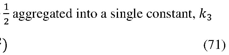 Assuming homogeneity of the composition of gas, mass flow rate is proportional to mole flow rate. Therefore (with constants aggregated into v): ^w = v^P^0^2 − P^`^2^ (72) [00171] This relationship was tested using pressure regulators upstream and downstream of a cassette vent with a flow meter attached. Linear regression confirms that this relationship is a good approximation as residuals appear to be minimal and the y-intercept is close to zero. See FIGS.56 and 57. [00172] Using (45) with the upstream pressure P^0^ set equal to P^^^ and the downstream pressure P^`^ = ^234: n′^^^ = v yP^^^2 − ^ 2 ^^^ z (73)
Using (36) with (46): l P^l^ V^l^ − P^k^ V^k^ = v m yP^|^2 − ^ 2 ^^^ z n| (74) k For brevity:
Assuming homogeneity of the composition of gas, mass flow rate is proportional to mole flow rate. Therefore (with constants aggregated into v): ^w = v^P^0^2 − P^`^2^ (72) [00171] This relationship was tested using pressure regulators upstream and downstream of a cassette vent with a flow meter attached. Linear regression confirms that this relationship is a good approximation as residuals appear to be minimal and the y-intercept is close to zero. See FIGS.56 and 57. [00172] Using (45) with the upstream pressure P^0^ set equal to P^^^ and the downstream pressure P^`^ = ^234: n′^^^ = v yP^^^2 − ^ 2 ^^^ z (73)
Using (36) with (46): l P^l^ V^l^ − P^k^ V^k^ = v m yP^|^2 − ^ 2 ^^^ z n| (74) k For brevity:
 o }^k, l^ = m ^P^|^7 − ^ 7 234 ^ n| (75) [00173] With reference to • b5: The time of the
 • b7: Four seconds after the completion of the final AVS sweep of startup test • b8: Three seconds before the slope filter detects the start of fill • b^: Three seconds after the maximum pressure when the user stops filling • b^: Three second after the pressure starts decaying and no filling is occurring or the time when the gauge pressure at the start of release decays by 20%, whichever occurs sooner • bj: Seven second after the pressure starts decaying and no filling is occurring or the time when the gauge pressure at the start of release decays by 80%, whichever occurs sooner Note that b^ and b^ may be equivalent if the user fills in a single action. If there are multiple fill and release segments, the post-fill release region, b^ to bj, is selected to use the region with the highest pressure. Additionally, a valid post-fill release region must not detect filling until at least 3 seconds has elapsed since the end of the region. This ensures that the release data is unaffected by filling, as there is some latency in the detection of fill is expected. [00174] A hierarchical state machine, Cassette Fill Hsm, is implemented in the software to monitor different stages of the filling process. The initial states and the states with active pressure monitoring are depicted in FIG.58. The following sums are calculated for the Pre-Fill Analysis Period and Post-Fill Analysis Period. These sums are required for calculating the check valve settled position and decay coefficient. { { { ^ ^ ^ ^^ 2 ^
[00175] Where: ; is the first index of the analysis period (corresponding to one of the regions defined above) { is the last index of the analysis period (corresponding to one of the regions defined above) [00176] To determine the integral calculations, use the following. The trapezoidal rule for integration is used to calculate }^k, l^. Using the standard definition, this is defined with the equation below. o0p }^k, l^ = ^ } ′^^^ + } ′^^ − 1^ Δτ (76) Where: Δτ is the constant sample
• b7: Four seconds after the completion of the final AVS sweep of startup test • b8: Three seconds before the slope filter detects the start of fill • b^: Three seconds after the maximum pressure when the user stops filling • b^: Three second after the pressure starts decaying and no filling is occurring or the time when the gauge pressure at the start of release decays by 20%, whichever occurs sooner • bj: Seven second after the pressure starts decaying and no filling is occurring or the time when the gauge pressure at the start of release decays by 80%, whichever occurs sooner Note that b^ and b^ may be equivalent if the user fills in a single action. If there are multiple fill and release segments, the post-fill release region, b^ to bj, is selected to use the region with the highest pressure. Additionally, a valid post-fill release region must not detect filling until at least 3 seconds has elapsed since the end of the region. This ensures that the release data is unaffected by filling, as there is some latency in the detection of fill is expected. [00174] A hierarchical state machine, Cassette Fill Hsm, is implemented in the software to monitor different stages of the filling process. The initial states and the states with active pressure monitoring are depicted in FIG.58. The following sums are calculated for the Pre-Fill Analysis Period and Post-Fill Analysis Period. These sums are required for calculating the check valve settled position and decay coefficient. { { { ^ ^ ^ ^^ 2 ^
[00175] Where: ; is the first index of the analysis period (corresponding to one of the regions defined above) { is the last index of the analysis period (corresponding to one of the regions defined above) [00176] To determine the integral calculations, use the following. The trapezoidal rule for integration is used to calculate }^k, l^. Using the standard definition, this is defined with the equation below. o0p }^k, l^ = ^ } ′^^^ + } ′^^ − 1^ Δτ (76) Where: Δτ is the constant sample
 }^^|^ = ^P^|^7 − ^ 7 234 ^ the constants Δτ⁄ 2 will be omitted in pump software. As a result, this scaling
 into the decay constant calculations. l−k }∗^k, l^ = ^ }^^^^ + }^^^ − 1^ (77) [00177] Linear regression is used The referenced definitions for
 ^ = ^ ∑ [:=: − ∑ [: ∑ =: ^ − ^7 (78) [00178] As the attachment of the and cassette may be separated from
 may start filling before the check valve can reach its nominal start position, the start position needs to be estimated through regression. Errors in calculating the wrong estimated preload will result in an error in a small error in the volume of air in the empty pump/cassette assembly. An example of the relationship between check valve travel and pressure is depicted in FIG.59. [00179] During the pressurization process, the preload of the system prevents significant displacement until approximately 1.0 to 1.5 psi. Displacement is then approximately linear with displacement. Upon relaxation, some hysteresis can be observed in which the pressure decreases a small amount without a decrease in displacement. The linear relationship between pressure and displacement occurs again until zero displacement is reached. [00180] If the minimum pressure is less than or equal to the nominal return pre-load of the pump, the maximum observed check valve position is used as the settled position. The measured check valve ADC
is greatest when it is settled and recessed into the pump midbody. If the minimum pressure is greater than the threshold, linear regression is used to estimate the settled position as described below. [00181] The check valve data in the Pre-Fill Release Region or Post-Fill Release Region is analyzed to estimate the check valve start position. The check valve positions in these regions are not expected to include the hysteresis behavior at the maximum pressure, as these regions start a few seconds after pressure starts decaying. Linear regression is performed over the analysis region to estimate the check valve settled position, with pressure as the independent variable and check valve position as the dependent variable. See FIG.60. [00182] Using the definitions in herein, the parameters of the linear model can be calculated with the equations below. ^ = ^ ∑ ^:^: − ∑ ^: ∑ ^: ^ ^ 7 : − ^:^7 (80) Where:
may start filling before the check valve can reach its nominal start position, the start position needs to be estimated through regression. Errors in calculating the wrong estimated preload will result in an error in a small error in the volume of air in the empty pump/cassette assembly. An example of the relationship between check valve travel and pressure is depicted in FIG.59. [00179] During the pressurization process, the preload of the system prevents significant displacement until approximately 1.0 to 1.5 psi. Displacement is then approximately linear with displacement. Upon relaxation, some hysteresis can be observed in which the pressure decreases a small amount without a decrease in displacement. The linear relationship between pressure and displacement occurs again until zero displacement is reached. [00180] If the minimum pressure is less than or equal to the nominal return pre-load of the pump, the maximum observed check valve position is used as the settled position. The measured check valve ADC
is greatest when it is settled and recessed into the pump midbody. If the minimum pressure is greater than the threshold, linear regression is used to estimate the settled position as described below. [00181] The check valve data in the Pre-Fill Release Region or Post-Fill Release Region is analyzed to estimate the check valve start position. The check valve positions in these regions are not expected to include the hysteresis behavior at the maximum pressure, as these regions start a few seconds after pressure starts decaying. Linear regression is performed over the analysis region to estimate the check valve settled position, with pressure as the independent variable and check valve position as the dependent variable. See FIG.60. [00182] Using the definitions in herein, the parameters of the linear model can be calculated with the equations below. ^ = ^ ∑ ^:^: − ∑ ^: ∑ ^: ^ ^ 7 : − ^:^7 (80) Where:
 ^ is the slope of the pressure/check valve relationship ~ is the y-intercept of the pressure/check valve relationship Using the terms defined in herein, (80) and (81) can be rewritten as: ^ = ^^^ − ^7^8 − ^ 7 (82)
 With the solved linear parameters, the preload pressure. ^^ = ^^^b^fa^n + ~ (84) If this calculated value is not within the expected range of optical positions, then the calculated value is rejected. Additionally, if a larger check valve position has been observed in comparison to the calculated value, the maximum observed check valve position is used as the settled position. [00183] After, the final AVS sweep of startup test, the pressure in the following four seconds are monitored (b5 to b7). If the pressure stops decreases due to reaching ambient pressure or the user filling the cassette, pre-fill analysis is canceled and the Cassette Fill Algorithm will rely on the post-fill release
data for estimating the check valve settled position and decay coefficient. If the analysis is not canceled, the algorithm will first estimate the settled check valve position as described herein. [00184] The check valve settled position is estimated as described herein. If the analysis calculates a check valve position that is rejected, then the pre-fill analysis is canceled. If the analysis is not canceled, the decay coefficient is estimated herein. [00185] Using (47), the decay coefficient can be calculated with linear regression using k = b5 and l = ^, from ^ = ^b5, b7^. P^^^ V^^^ = v}^b1, ^^ + P^b1^ V^b1^ Note that this is in the form of a linear equation = = ^[ + ~, where:
With the solved linear parameters, the preload pressure. ^^ = ^^^b^fa^n + ~ (84) If this calculated value is not within the expected range of optical positions, then the calculated value is rejected. Additionally, if a larger check valve position has been observed in comparison to the calculated value, the maximum observed check valve position is used as the settled position. [00183] After, the final AVS sweep of startup test, the pressure in the following four seconds are monitored (b5 to b7). If the pressure stops decreases due to reaching ambient pressure or the user filling the cassette, pre-fill analysis is canceled and the Cassette Fill Algorithm will rely on the post-fill release
data for estimating the check valve settled position and decay coefficient. If the analysis is not canceled, the algorithm will first estimate the settled check valve position as described herein. [00184] The check valve settled position is estimated as described herein. If the analysis calculates a check valve position that is rejected, then the pre-fill analysis is canceled. If the analysis is not canceled, the decay coefficient is estimated herein. [00185] Using (47), the decay coefficient can be calculated with linear regression using k = b5 and l = ^, from ^ = ^b5, b7^. P^^^ V^^^ = v}^b1, ^^ + P^b1^ V^b1^ Note that this is in the form of a linear equation = = ^[ + ~, where:
 = = P^^^ V^^^ ^ = v [ = }^b5, ^^ ~ = P^b5^ V^b5^ Least-square linear regression is performed over the Pre-Fill Analysis Region to solve for the slope, which is equal to the decay coefficient v. Refer to (78) for the equation to calculate slope. Note that the calculation of = requires volume. As the cassette has not been filled, F^^^ = 0, and the equation for volume from (37) simplifies to: V^^^ = ^0 + W^^^ (assuming cassette is empty) (86) [00186] For calculation efficiency, the sums are updated while the data is collected. As the
 settled position is unknown at this point, the sums ∑ =: and ∑ [:=:, which include V^^^, cannot be computed directly. Instead, the running sums are calculated as derived in (88) and (89). The definition for ∑ =: is expanded with (86) and (62). { { ^ = ^ ^^^^ − ^^^^ Where:
 ; is the index for b5 { is the This is rearranged into the equation below, in which the settled check valve position does not need to be known while accumulating the sums. { { { ^ ^ '^ ^
The sum for ∑ [:=: is solved in a similar manner and results in the equation below. { { { ^ [^=^ = '^^0 + ^^^^ ^ };,^^^ , − '^ ^ };,^^^^^ , (89) Using the terms defined,
; is the index for b5 { is the This is rearranged into the equation below, in which the settled check valve position does not need to be known while accumulating the sums. { { { ^ ^ '^ ^
The sum for ∑ [:=: is solved in a similar manner and results in the equation below. { { { ^ [^=^ = '^^0 + ^^^^ ^ };,^^^ , − '^ ^ };,^^^^^ , (89) Using the terms defined,
 { ^ =^ = ^^0 + ^^^^^2 − ^^7 (90) [00187] The decay constant is
 expected range, the value is performed if the decay constant could not be calculated. [00188] The check valve settled position is estimated. If the analysis calculates a check valve position that is rejected, then the maximum observed check valve value is used as the settled position. Using (47), the decay coefficient can be calculated with linear regression using k = b^ and l = ^, from ^ = ^b^, bj^. P^^^ V^^^ = v}^b5, ^^ + P^b5^ V^b5^ (92) Note that this is in the form of a linear equation = = ^[ + ~, where: = = P^^^ V^^^ ^ = v [ = }^b^, ^^ ~ = P^b^^ V^b^^ Least-square linear regression is performed over the Post-Fill Analysis Region to model the slope and y- intercept, which are equal to the decay coefficient v and the product P^b^^ V^b^^ respectively. . Note that the calculation of = requires volume. As the cassette fill volume is constant during this region, the equation for volume from (37) equates to the following. V^^^ = ^0 + W^^^ − <^a^ (for ^ = ^b (9 ^, bj^) 3) Where:
 <^^/ is the fill volume during the Post-Fill Release Region. The definition for ∑ =: is expanded with (93) and (62).
{ { ^ =^ = ^ ^^^^0 + ^^^^ − ^^^ − <^a^^ (94) Where: ; is the index for b^
<^^/ is the fill volume during the Post-Fill Release Region. The definition for ∑ =: is expanded with (93) and (62).
{ { ^ =^ = ^ ^^^^0 + ^^^^ − ^^^ − <^a^^ (94) Where: ; is the index for b^
 { is the index for bj This is rearranged into the equation below. { { { ^ =^ = ^^0 + ^^^ − <^a^^ ^ ^^ − ^ ^ ^^^^ (95) The sum for ∑ [:=: is
 { { { ^ [^=^ = ^^0 + ^^^ − <^a^^ ^ };,^^^ − ^ ^ };,^^^^^ (96) For brevity:
 ^ = ^1 + ^^/ − <^^/ (97) Using the terms defined herein and (97), (95) and (96) can be rewritten as: { ^ =^ = − (98)
 Using the definitions herein, the can below. ^^^^ − ^^ ^ − ^ ^^^ − ^ ^ v = ^ ^ 5 7 ^^ (100) [00189] As the fill volume has
 and an additional equation is required to solve for decay coefficient. Using (47), the decay coefficient can be calculated with linear regression using k = b8 and l = b^. P^b5^ V^b5^ = v}^b3, b5^ + P^b3^ V^b3^ (102)
As the cassette has not been filled, F^^^ = 0, and the equation for volume from (37) with (62) simplifies to: V^b3^ = ^0 + ^^^^ − ^^b3^^ (103) Therefore, (102) can be rewritten as: P^b5^ V^b5^ = v}^b3, b5^ + P^b3^ y^0 + ^^^^ − ^^b3^^z (104) Post-Fill Decay Constant Calculation To solve for the decay constant, (100) is rearranged to solve for ^. v^^^^ − ^ 7 5 ^ + ^^^^ − ^ ^ ^ ^ = ^ 5 ^ (105) ^^^^ − This equation is then substituted
and an additional equation is required to solve for decay coefficient. Using (47), the decay coefficient can be calculated with linear regression using k = b8 and l = b^. P^b5^ V^b5^ = v}^b3, b5^ + P^b3^ V^b3^ (102)
As the cassette has not been filled, F^^^ = 0, and the equation for volume from (37) with (62) simplifies to: V^b3^ = ^0 + ^^^^ − ^^b3^^ (103) Therefore, (102) can be rewritten as: P^b5^ V^b5^ = v}^b3, b5^ + P^b3^ y^0 + ^^^^ − ^^b3^^z (104) Post-Fill Decay Constant Calculation To solve for the decay constant, (100) is rearranged to solve for ^. v^^^^ − ^ 7 5 ^ + ^^^^ − ^ ^ ^ ^ = ^ 5 ^ (105) ^^^^ − This equation is then substituted
 . v y^^ 2 4 − ^1 z + ^^^^8 − ^1^7^ ^ − ^ ^2 − ^^7 − v^1 The two
 v}^b8, b^^ + P^b8^ y^1 + ^^^/ − ^^b8^^z
 Solve for v. P^b8^ y^1 + ^^^/ − ^^b8^^z ^^^^ − ^5^7^ + ^^^^^^ − ^7^^^ [00190] With a
 P^b4^ V^b4^ = v}^b3, b4^ + P^k^ yb3 + ^^^^ − ^^b3^^z (109) Substituting (37) and (62) for the definition of V^b^^ and then solving for F^b^^ results in the equation below. P^b4^ ^^0 + ^^^^ − ^^b4^^ − F^b4^^ = v}^b3, b4^ + P^k^ yb3 + ^^^^ − ^^b3^^z (110)
v}^b F b 3, b4^ + P^k^ yb3 + ^^^^ − ^^b3^^z ^ 4^ = ^0 + ^^^^ − ^^b4^^ − (111) P^b4^ [00191] The
P^b4^ V^b4^ = v}^b3, b4^ + P^k^ yb3 + ^^^^ − ^^b3^^z (109) Substituting (37) and (62) for the definition of V^b^^ and then solving for F^b^^ results in the equation below. P^b4^ ^^0 + ^^^^ − ^^b4^^ − F^b4^^ = v}^b3, b4^ + P^k^ yb3 + ^^^^ − ^^b3^^z (110)
v}^b F b 3, b4^ + P^k^ yb3 + ^^^^ − ^^b3^^z ^ 4^ = ^0 + ^^^^ − ^^b4^^ − (111) P^b4^ [00191] The
 assembly 104 to the cassette assembly 102. When reusable pump assembly 104 and cassette assembly 102 are properly engaged by use of the lock ring 154 and cassette tabs 166, the assemblies form an air tight seal along the circumference. Air is trapped in the internal pump cavity 150 and causes an increase or spike in air pressure sensed by the pressure sensor 617 before the air pressure can equalize by exiting the vent 152. Failure to detect a spike in air pressure by the pressure sensor 617, an increase in the air pressure above a predetermined amount, when other sensors, such a Hall sensor 633 indicate proper rotational alignment of the reusable pump assembly 104 and cassette assembly 102. Failure of the pump controller 108 to measure the expected air pressure spike detected by the pressure sensor 617 within a predetermined time window, while simultaneously detecting correct rotational alignment by the Hall sensor 633, will result in the pump controller issuing an alarm sounded from the infusion pump 100 and/or the infusion pump 100 communicating an alarm signal to the remote controller 130 to trigger a visual and/or audio alarm. The user will then be instructed by the display on the controller 130 [00192] The pump controller 108 of the infusion pump 100 has a controls layer 801. The control layer 801 includes a Pulse Scheduler Subsystem 802, a self-prime subsystem 804, a delivery subsystem 806, a infusion pump subsystem 808, an AVS subsystem 810, and a delivery monitor subsystem 812 as shown in Fig.27. The pulse scheduler subsystem 802 commands delivery monitor HSM 814 to deliver fluid 119 according to the delivery schedule during active delivery. The self-prime subsystem 804 coordinates priming the fluid path and performing initial pump actuator targeting deliveries by the pump actuator 105A by commanding the delivery subsystem 806 and the infusion pump subsystem 808 during the self- prime sequence. The delivery subsystem 806 coordinates the delivery of fluid 119 by commanding the AVS 148 and infusion pump subsystems 808 according to commands from either the pulse scheduler subsystem 802 or the self-prime subsystem 804 and performs runtime checks during normal delivery. Normal delivery is when the drug delivery system 10 is delivering predetermined quantities of fluid to the patient. Self-prime, is when the drug delivery system 10 is moving fluid 119 from the reservoir 118 to substantially fill the fluid passages 629, 625, 619, 623, 621, AVS volume chamber and other fluid portions of the infusion pump 100 in preparation for delivering fluid 119 to the user during normal delivery. The delivery monitor subsystem 812 monitors the self-prime subsystem 804, delivery subsystem 806, AVS subsystem 810, and infusion pump subsystem 808 by independently verifying the pumping behavior and results of the infusion pump 100.
[00193] The following terms are used as identified acronyms, Analog-to-Digital Converter (ADC); Field- Effect Transistor (FET); Inter-Processor Communication (IPC) The transmission and reception of messages between the command and supervisor processor 811s; Interrupt Service Routine (ISR) The transmission and reception of messages between the command and supervisor processor 811s; and Pulse Width Modulation (PWM). [00194] The pulse scheduler subsystem 802 provides the interface between the therapy subsystem and the delivery controller subsystem while the system is not performing the self-prime sequence. The pulse scheduler subsystem 802 takes the volume and rate based therapy objects registered by the therapy subsystem and converts that information into delivery pulse volumes of fluid 119 at predetermined delivery times. The general structure of the pulse scheduler 816 is shown in Fig.28. All calculations are detailed in the following sections. [00195] The target aliquot volume of fluid 119 is calculated from the rate based therapy objects by multiplying the rate by the Vpd desired nominal time between deliveries. The target aliquot volume is calculated via the following equation: ^^ = ^w ∗ ^:^4 [00196] where ^^ is the unlimited target is the rate sum of the rate based therapy objects, and ^:^4 is the nominal time
assembly 104 to the cassette assembly 102. When reusable pump assembly 104 and cassette assembly 102 are properly engaged by use of the lock ring 154 and cassette tabs 166, the assemblies form an air tight seal along the circumference. Air is trapped in the internal pump cavity 150 and causes an increase or spike in air pressure sensed by the pressure sensor 617 before the air pressure can equalize by exiting the vent 152. Failure to detect a spike in air pressure by the pressure sensor 617, an increase in the air pressure above a predetermined amount, when other sensors, such a Hall sensor 633 indicate proper rotational alignment of the reusable pump assembly 104 and cassette assembly 102. Failure of the pump controller 108 to measure the expected air pressure spike detected by the pressure sensor 617 within a predetermined time window, while simultaneously detecting correct rotational alignment by the Hall sensor 633, will result in the pump controller issuing an alarm sounded from the infusion pump 100 and/or the infusion pump 100 communicating an alarm signal to the remote controller 130 to trigger a visual and/or audio alarm. The user will then be instructed by the display on the controller 130 [00192] The pump controller 108 of the infusion pump 100 has a controls layer 801. The control layer 801 includes a Pulse Scheduler Subsystem 802, a self-prime subsystem 804, a delivery subsystem 806, a infusion pump subsystem 808, an AVS subsystem 810, and a delivery monitor subsystem 812 as shown in Fig.27. The pulse scheduler subsystem 802 commands delivery monitor HSM 814 to deliver fluid 119 according to the delivery schedule during active delivery. The self-prime subsystem 804 coordinates priming the fluid path and performing initial pump actuator targeting deliveries by the pump actuator 105A by commanding the delivery subsystem 806 and the infusion pump subsystem 808 during the self- prime sequence. The delivery subsystem 806 coordinates the delivery of fluid 119 by commanding the AVS 148 and infusion pump subsystems 808 according to commands from either the pulse scheduler subsystem 802 or the self-prime subsystem 804 and performs runtime checks during normal delivery. Normal delivery is when the drug delivery system 10 is delivering predetermined quantities of fluid to the patient. Self-prime, is when the drug delivery system 10 is moving fluid 119 from the reservoir 118 to substantially fill the fluid passages 629, 625, 619, 623, 621, AVS volume chamber and other fluid portions of the infusion pump 100 in preparation for delivering fluid 119 to the user during normal delivery. The delivery monitor subsystem 812 monitors the self-prime subsystem 804, delivery subsystem 806, AVS subsystem 810, and infusion pump subsystem 808 by independently verifying the pumping behavior and results of the infusion pump 100.
[00193] The following terms are used as identified acronyms, Analog-to-Digital Converter (ADC); Field- Effect Transistor (FET); Inter-Processor Communication (IPC) The transmission and reception of messages between the command and supervisor processor 811s; Interrupt Service Routine (ISR) The transmission and reception of messages between the command and supervisor processor 811s; and Pulse Width Modulation (PWM). [00194] The pulse scheduler subsystem 802 provides the interface between the therapy subsystem and the delivery controller subsystem while the system is not performing the self-prime sequence. The pulse scheduler subsystem 802 takes the volume and rate based therapy objects registered by the therapy subsystem and converts that information into delivery pulse volumes of fluid 119 at predetermined delivery times. The general structure of the pulse scheduler 816 is shown in Fig.28. All calculations are detailed in the following sections. [00195] The target aliquot volume of fluid 119 is calculated from the rate based therapy objects by multiplying the rate by the Vpd desired nominal time between deliveries. The target aliquot volume is calculated via the following equation: ^^ = ^w ∗ ^:^4 [00196] where ^^ is the unlimited target is the rate sum of the rate based therapy objects, and ^:^4 is the nominal time
 is equal to five minutes. Finally, the target aliquot volume is limited to volumes that the infusion pump 100 can achieve. This is accomplished through the following equation: ^2,4%:, ^^ < ^2,4%: [00197] ^2&%^^^3 = ^ ^^, ^ 2,4%: ≤ ^ ^ ≤ ^ 2,42 ^2,42 , ca^nimum achievable aliquot volume, and ^^ > ^2,42
 aliquot volume. The result of these calculations can be seen in Fig. 29. This figure only shows rates between 0 and 25.5μL/hr. Note that all rates above 24μL/hr have the same target aliquot volume of 2μL. [00198] The pending volume is calculated as a sum of the volumes from all rate based therapy objects and volume based therapy objects. The pending volume is calculated via the following equation: ^^S:M = ^£ + ^¤ [00199] Where ^£ is the sum of volumes from all of the volume based therapy objects and ^¤ is the sum of volumes from all of the rate based therapy objects. [00200] Once the pulse scheduler 816 has calculated the target aliquot volume of fluid 119 based on the rate based therapy objects and the pending volume based on all therapy objects, the pulse scheduler 816 then calculates a potential delivery volume of fluid 119 based on the active therapy objects and their relative sizes. The potential delivery volume is calculated using one of the following equations:
[00201] If the sum of volumes from all volume based therapy objects (^£) is smaller than or equal to the target aliquot volume (^2&%^^^3), ^2&%^^^3 is used as the potential delivery volume. The following equation is used: ^^M = ^2&%^^^3 [00202] If the sum of volumes from all volume based therapy objects (^£) is larger than the target aliquot volume (^2&%^^^3), the pending volume (^^S:M) is limited to the volume the pump can achieve and used as the potential delivery volume. This allows the pump to maximize the aliquot size used if volume based therapy objects are active, allowing the volume based therapy objects to be delivered in the minimum number of discrete aliquots possible. The following equation is used: ^ , [00203] ^^M = ¥ ^S:M ^^S:M < ^2,42 ^2,42 , ^^S:M ≥ ^2,42 ume based therapy object is not active, the potential volume. The following equation is used:
aliquot volume. The result of these calculations can be seen in Fig. 29. This figure only shows rates between 0 and 25.5μL/hr. Note that all rates above 24μL/hr have the same target aliquot volume of 2μL. [00198] The pending volume is calculated as a sum of the volumes from all rate based therapy objects and volume based therapy objects. The pending volume is calculated via the following equation: ^^S:M = ^£ + ^¤ [00199] Where ^£ is the sum of volumes from all of the volume based therapy objects and ^¤ is the sum of volumes from all of the rate based therapy objects. [00200] Once the pulse scheduler 816 has calculated the target aliquot volume of fluid 119 based on the rate based therapy objects and the pending volume based on all therapy objects, the pulse scheduler 816 then calculates a potential delivery volume of fluid 119 based on the active therapy objects and their relative sizes. The potential delivery volume is calculated using one of the following equations:
[00201] If the sum of volumes from all volume based therapy objects (^£) is smaller than or equal to the target aliquot volume (^2&%^^^3), ^2&%^^^3 is used as the potential delivery volume. The following equation is used: ^^M = ^2&%^^^3 [00202] If the sum of volumes from all volume based therapy objects (^£) is larger than the target aliquot volume (^2&%^^^3), the pending volume (^^S:M) is limited to the volume the pump can achieve and used as the potential delivery volume. This allows the pump to maximize the aliquot size used if volume based therapy objects are active, allowing the volume based therapy objects to be delivered in the minimum number of discrete aliquots possible. The following equation is used: ^ , [00203] ^^M = ¥ ^S:M ^^S:M < ^2,42 ^2,42 , ^^S:M ≥ ^2,42 ume based therapy object is not active, the potential volume. The following equation is used:
 = 0 [00204] This supports the behavior of limiting the aliquots requested below the maximum aliquot size at the end of each bolus. For all boluses whose requested volume was larger than the maximum aliquot size, the Therapy Subsystem will set the therapy object to inactive once one aliquot below the maximum aliquot size has been performed, allowing the system to attempt only one discrete aliquot less than the maximum aliquot size at the end of these boluses. [00205] If the potential delivery volume, ^^M, is greater than or equal to the target aliquot volume, ^2&%^^^3, the pulse scheduler 816 commands the delivery subsystem 806 to deliver the potential delivery volume of fluid 119 immediately. Otherwise, the pulse scheduler 816 sets a timer to recalculate the potential delivery volume when the pulse scheduler 816 expects the pending volume of the rate based therapy object to reach the target aliquot volume. [00206] If the potential delivery volume of fluid 119 is less than the target aliquot volume then the pulse scheduler subsystem 802 schedules another delivery volume calculation when it expects the delivery volume will equal the target aliquot volume or when the pulse scheduler 816 will be forced to make a delivery in order to maintain the periodicity of the current therapy. [00207] In order to determine how long the pulse scheduler 816 needs to wait to recalculate the potential delivery volume of fluid 119, the pulse scheduler 816 first calculates the time when the delivery volume will be equal to the target aliquot volume. To start this calculation, the pulse scheduler 816 calculates the volume needed to reach the target aliquot volume: ^M%$$ = ^2&%^^^3 − ^^M
[00208] where ^M%$$ is the volume that needs to accumulate before the delivery volume is equal to the target aliquot volume. The time necessary to accumulate the volume is then calculated: ^ ^ = § M%$$ M%$$ ^w ¨ [00209] where ^M%$$ is the time needed to and ^w is the rate sum of the rate based The ceiling function
= 0 [00204] This supports the behavior of limiting the aliquots requested below the maximum aliquot size at the end of each bolus. For all boluses whose requested volume was larger than the maximum aliquot size, the Therapy Subsystem will set the therapy object to inactive once one aliquot below the maximum aliquot size has been performed, allowing the system to attempt only one discrete aliquot less than the maximum aliquot size at the end of these boluses. [00205] If the potential delivery volume, ^^M, is greater than or equal to the target aliquot volume, ^2&%^^^3, the pulse scheduler 816 commands the delivery subsystem 806 to deliver the potential delivery volume of fluid 119 immediately. Otherwise, the pulse scheduler 816 sets a timer to recalculate the potential delivery volume when the pulse scheduler 816 expects the pending volume of the rate based therapy object to reach the target aliquot volume. [00206] If the potential delivery volume of fluid 119 is less than the target aliquot volume then the pulse scheduler subsystem 802 schedules another delivery volume calculation when it expects the delivery volume will equal the target aliquot volume or when the pulse scheduler 816 will be forced to make a delivery in order to maintain the periodicity of the current therapy. [00207] In order to determine how long the pulse scheduler 816 needs to wait to recalculate the potential delivery volume of fluid 119, the pulse scheduler 816 first calculates the time when the delivery volume will be equal to the target aliquot volume. To start this calculation, the pulse scheduler 816 calculates the volume needed to reach the target aliquot volume: ^M%$$ = ^2&%^^^3 − ^^M
[00208] where ^M%$$ is the volume that needs to accumulate before the delivery volume is equal to the target aliquot volume. The time necessary to accumulate the volume is then calculated: ^ ^ = § M%$$ M%$$ ^w ¨ [00209] where ^M%$$ is the time needed to and ^w is the rate sum of the rate based The ceiling function
 pulse scheduler 816 calculates the delivery
 119 again, it will be greater than or equal to the target aliquot volume of the fluid 119. Once the pulse scheduler 816 calculates the time needed to accumulate the volume difference, it limits this time to the maximum time between deliveries, taking into account the amount of time that has passed since the last delivery. The pulse scheduler 816 calculates the maximum time between deliveries via the following equation: [00210] ^&%4%3 = ^42 − ^S&2^/SM©ªCªB the maximum time limit, ^42 mum time between deliveries of ^S&2^/SM is the amount of time that has elapsed since the last delivery. The reschedule time
 is then calculated using the following equation: ^4%:, ^M%$$ < ^4%: [00211] ^¤S/^«SM^&S = ^^M%$$ , ^4%: ≤ ^M%$$ ≤ ^&%4%3¬®¯°±²©l the pulse scheduler 816 recalculates the ^&%4%3, ^M%$$ > ^&%4%3 delivery volume and ^4%:mum time between deliveries. With this information, the pulse scheduler 816 waits ^¤S/^«SM^&S time before calculating the delivery volume again. If ^&%4%3 is reached before the delivery volume is equal to the target aliquot volume, then the
 816 commands a delivery of the delivery volume, limited to at least the minimum aliquot volume, at that time. [00212] Finally, if at any point the therapy subsystem changes any of the therapy objects, then the therapy subsystem will call the pulse scheduler subsystem 802 to recalculate the target aliquot volume, potential delivery volume, and delivery time. If the delivery controller subsystem 806 is not currently busy then the pulse scheduler subsystem will do so immediately, otherwise the pulse scheduler will reschedule itself ^4%:re until the delivery state machine is no longer busy. FIG. 30 shows the nominal time between deliveries for rates between 1.0μL/hr and 100μL/hr. [00213] The self-prime subsystem 804 provides the interface between the therapy subsystem and the delivery subsystem 806 and infusion pump subsystem 808 while the command processor 800 is priming the cassette assembly 102. FIG.31 shows the actions taken by the self-prime subsystem 804 while priming is active as well as the ways in which priming is started, stopped, and completed by the therapy subsystem. While priming is active, the self-prime subsystem 804 progresses through the phases of the self-priming sequence as shown on the right side of the figure and commands either deliveries from the delivery subsystem or self-prime actuations from the infusion pump subsystem 808. The self-prime
subsystem 804 starts, stops, and completes priming when commanded by the therapy subsystem, or automatically stops when the maximum number of priming strokes of the pump actuator 105A have been performed. [00214] The self-priming sequence 818 is illustrated on the right side of FIG.31. The self-priming sequence 818 is split into three phases, each of which is detailed in the following sections. The self- priming sequence 818 can be stopped and re-started at any point in the self-prime sequence 818 until self- prime is completed. When the self-priming sequence 818 is re-started, the self-prime subsystem 804 resumes the self-priming sequence 818 at the same point in the process at which it was stopped. [00215] During the initial prime phase 820 of the self-priming sequence 818, the self-prime subsystem 804 commands self-prime actuations of the pump actuator 105A from the infusion pump subsystem 808. The purpose of this initial prime phase 820 is to purge as much air as possible from the fluid path of the cassette assembly 102 (the fluid path being the fluid passages 629, 625, 619, 623, 621, AVS chamber 631, valve seats 610B, 612B, 614B, and pump chamber 105B). The self-prime subsystem 804 will move to a delivery controller targeting phase 822 once the minimum number of self-prime actuations of the pump actuator 105A has been performed. The minimum number of self-prime actuations is set as the number of actuations of the pump actuator 105A expected to prime the fluid path of the cassette assembly 102 as determined from experimental data performed in a worst case priming situation. If the self-priming sequence 818 is stopped and re-started while in the initial prime phase 820, the number of priming strokes of the pump actuator 105A already performed is not reset. [00216] During the delivery controller targeting phase 822 of the self-priming sequence 818, the self- prime subsystem 804 commands deliveries from the delivery subsystem 806. The purpose of the delivery controller targeting phase 822 is to allow the delivery controller 807 to perform initial targeting deliveries in preparation for the infusion device 128 filling and the initiation of delivery. The self-prime subsystem 804 will move to a continued prime phase 824 once the delivery controller 807 is in the normal control mode, signaling that initial targeting is complete. [00217] If three primary runtime modeling delivery failures are reported while in delivery controller targeting phase 822 of the self-prime sequence, the self-prime subsystem will revert back to initial prime phase 820 to retry the minimum number of self-prime actuations of the pump actuator 105A. Failures of primary runtime modeling deliveries are often caused by air in the fluid path, and will prevent the delivery controller 807 from entering the normal control mode. The initial prime phase 820 and delivery controller targeting phase 822 can be attempted up to two times. On the second attempt, the self-prime subsystem 804 will not revert back to Initial prime phase 820 for primary runtime modeling failures and the delivery subsystem 806 will report an alarm if the normal control mode cannot be entered. This retry
logic increases the pump controller 108 robustness to removed air in the reservoir 118 during self-prime, but allows the detection of a cassette assembly 102 that is not functioning properly. [00218] In an alternate embodiment as described in FIG.31A, During the continued prime phase 824, the self-prime subsystem 804 commands deliveries from the infusion pump subsystem 808. The purpose of this phase is to allow the Delivery Controller to perform check valve modeling in preparation for the cannula fill and the initiation of delivery. The infusion pump subsystem 808 will move to Phase 3 once the Delivery Controller is in the Normal Control Mode, signaling that check valve modeling has passed. If check valve modeling fails to determine cracking travel of the pump actuator 105A, the Self Prime Subsystem will revert to Phase 1 to retry the minimum number of Self Prime actuations. Failures of check valve modeling deliveries are often caused by air in the fluid passages 625, 629, 613, 619, 621 and will prevent the Delivery Controller from entering the Normal Control Mode. Phases 1 and 2 may be attempted up to two times. On the second attempt, the Self Prime subsystem will report an alarm if check valve modeling fails. This retry logic increases the system's robustness to air in the reservoir during Self Prime, but allows the detection of a CASSETTE that is not functioning properly. [00219] During the continued prime phase 824, the self-prime subsystem 804 commands self-prime actuations directly from the infusion pump subsystem 808. The purpose of this continued prime phase 824 is to continue priming fluid 119 as quickly as possible until the user stops priming. The self-prime subsystem 804 will remain in this phase until priming is stopped. Priming is stopped either when commanded by the therapy subsystem or when the maximum number of self-prime strokes of the pump actuator 105A has been performed. [00220] The self-prime subsystem 804 is commanded to start, stop, and complete self-prime by the therapy subsystem when priming is started, stopped, and completed by the user. In addition, the self- prime subsystem 804 stops prime if the number of priming actuations of the pump actuator 105A performed is above the preset limit. [00221] The self-prime subsystem 804 starts priming when commanded by the therapy subsystem as initiated by the user. Once priming has started, the self-prime subsystem 804 will progress through the steps described in the self-prime sequence 818 until priming is stopped. [00222] The self-prime subsystem 804 stops priming when commanded by the therapy subsystem or when the maximum number of self-prime strokes of the pump actuator 105A has been performed. The maximum number of self-prime strokes is set as the maximum number of strokes expected to prime the maximum length infusion set of tubing 184 and infusion device 128 as determined by experimental data. The maximum number of self-prime strokes of the pump actuator 105A is reset each time the user starts or re-starts priming, meaning the maximum number of self-prime strokes will be performed before the
system stops itself each time user commands prime start. This check is intended to ensure the pump controller 108 will not prime excessive fluid 119 if the user never stops priming. [00223] Self-prime can be stopped and re-started indefinitely until prime is completed. Each time self- prime is re-started, it resumes at the same phase (initial prime phase 820, delivery controller targeting phase 822, or continued prime phase 824) of the self-prime sequence 818 as when it was last stopped. [00224] Prime complete 826 is commanded by the therapy subsystem and causes the self-prime subsystem 804 to enter prime complete 826. Prime complete 826 is allowed at any phase (initial prime phase 820, delivery controller targeting phase 822, or continued prime phase 824) of the self-prime sequence. Once prime complete 826 has been entered, self-prime cannot be started again until the pump 105 is reset. Because the pump 105 and valve SMWs 610C, 612C are only actuated simultaneously during self-prime actuations of the pump actuator 105A, this prevents the pump 105 and valve SMWs 610C, 612C from being actuated simultaneously during normal delivery. [00225] The self-prime sequence is as follows: the pump SMW 112 and the measurement valve SMW 610C are simultaneously actuated. The measurement valve 610 is moved linearly near the limit of its range of travel, lifting the volume sensor valve actuator 612A and releasing all pressure downstream of the pump chamber 105B. At the same time, the reservoir valve actuator 614A occludes the flow path between the pump chamber 105B and reservoir 118, and the pump actuator 105A is linearly moved downwardly to the bottom of the pump chamber 105B, forcing as much fluid 119 and air in the pump chamber 105B as possible through the fluid passage 619. [00226] The actuation of each SMW 112, 612C are accomplished using the SMW control switches 920 and the SMW supervisor switch 922 as shown in FIG.32. The SMW supervisor switch 922 is controlled by the supervisor processor 811 and provides a switch between the battery voltage and the SMWs 112, 612C. This SMW supervisor switch 922 is normally off and prevents the command processor 800 from actuating the pump SMW 112 without action from the supervisor processor 811. The SMW control switches 920 are FETs actuated via PWM by the command processor 800 and provide control of the amount of current flowing through each SMW 112, 612C. [00227] The position of the pump actuator 105A, measurement valve actuator 610A, and volume sensor valve actuator 612A are measured using optical sensors 640, 644 and 642 respectively. This allows the Command Processor 800 to provide closed-loop control of the positions of the pump actuator 105A, measurement valve actuator 610A, and volume sensor valve actuator 612A by comparing the output of the respective optical sensors 640, 644, 642 to the target position and modifying the PWM of the SMW switches 920. The optical sensor 642 on the volume sensor valve actuator 612A is used either for PWM control of the position of the volume sensor valve actuator 612A during the priming process or to detect movement when fluid 119 has passed through past the volume sensor valve assembly 612 and fluid
passage 619 into the AVS 148, depending on the type of stroke of the volume sensor valve actuator 612A being performed. Using the volume sensor valve optical sensor 642 signal to detect when fluid 119 has entered the AVS 148 provides additional visibility to detect faults such as an open volume sensor valve assembly 612. [00228] The two SMW control switches 920 should not be closed at the same time to avoid pulling down the battery voltage low enough to brown out the electrical system of the pump controller 108. For all actuations except for self-prime actuations, the pump SMW 112 and measurement sensor valve SMW 612C are not actuated simultaneously. To avoid closing the SMW control switches 920 at the same time while the SMWs 112, 612C are actuated simultaneously during priming, the pump PWM 924 “on time” occurs in the first portion of the PWM period 828 while the valve PWM 926 “on time” occurs in the last portion of the PWM period 828. The pump controller 108 enforces that the sum of the PWM duty cycle commanded for both the pump PMW 924 and the valve PMW 926 does not exceed 100%, so the SMW control switches 920 are never closed at the same time. FIG.33 shows an example of the waveforms of the pump PWM 924 and valve PWM 926 during a simultaneous actuation over a PWM period 828. [00229] In addition to control of the pump actuator 105A and valve actuators 610A, 612A, voltages are measured at the pump sense line 821, valve sense line 823, and battery sense line 825 so the pump controller 108 can detect a broken SMW 112, 612C, failed FET, or depleted battery. m Total mass of the SMW Tn Current SMW temperature Ti Initial SMW temperature Ta Ambient temperature I Current V Applied voltage R Electrical Resistance h Heat transfer coefficient [W/K] C Heat capacity [J/kg/K] η Duty cycle [00230] The pump controller 108 uses a proportional controller with a fixed feed-forward term to control the position of the pump actuator 105A, measurement valve actuator 610A, and the volume sensor valve actuator 612A as shown in FIG.34. The heating of the SMW’s 112, 610C, 612C is an integrating process so a simple proportional controller is adequate for controlling position. A fixed duty-cycle feed forward term is used to provide quicker initial heating for each of the SMW’s 112, 610C, 612C and to compensate
for the heat loss of each of the SMW’s112, 610C, 612C to the surrounding environment. This feed forward term is a hard-coded value determined experimentally. The output of the pump controller 108 is limited to the valid PWM range (0% to 100%). The signal from each of the optical sensors 640, 642, 644 is low pass filtered with a single-pole discrete filter 930. [00231] The control algorithm is updated at a frequency of 1 kHz to give time for the ISR to complete. This results in a resolution of the total “on time” of the infusion pump 100 of 1 ms. [00232] The command processor 800 senses the loaded battery voltage through a resistor-divider to an ADC input. Approximately ten Tau (τ) are needed to get an error of less than ±0.5 LSB. τ is defined by the following equation: ^³24^&S ≥ ln^2^^5^ × ^^/ + ^µ^ × ^µ + 800 ^^ [00233] Where N is the impedance, ^µ is the internal
816 commands a delivery of the delivery volume, limited to at least the minimum aliquot volume, at that time. [00212] Finally, if at any point the therapy subsystem changes any of the therapy objects, then the therapy subsystem will call the pulse scheduler subsystem 802 to recalculate the target aliquot volume, potential delivery volume, and delivery time. If the delivery controller subsystem 806 is not currently busy then the pulse scheduler subsystem will do so immediately, otherwise the pulse scheduler will reschedule itself ^4%:re until the delivery state machine is no longer busy. FIG. 30 shows the nominal time between deliveries for rates between 1.0μL/hr and 100μL/hr. [00213] The self-prime subsystem 804 provides the interface between the therapy subsystem and the delivery subsystem 806 and infusion pump subsystem 808 while the command processor 800 is priming the cassette assembly 102. FIG.31 shows the actions taken by the self-prime subsystem 804 while priming is active as well as the ways in which priming is started, stopped, and completed by the therapy subsystem. While priming is active, the self-prime subsystem 804 progresses through the phases of the self-priming sequence as shown on the right side of the figure and commands either deliveries from the delivery subsystem or self-prime actuations from the infusion pump subsystem 808. The self-prime
subsystem 804 starts, stops, and completes priming when commanded by the therapy subsystem, or automatically stops when the maximum number of priming strokes of the pump actuator 105A have been performed. [00214] The self-priming sequence 818 is illustrated on the right side of FIG.31. The self-priming sequence 818 is split into three phases, each of which is detailed in the following sections. The self- priming sequence 818 can be stopped and re-started at any point in the self-prime sequence 818 until self- prime is completed. When the self-priming sequence 818 is re-started, the self-prime subsystem 804 resumes the self-priming sequence 818 at the same point in the process at which it was stopped. [00215] During the initial prime phase 820 of the self-priming sequence 818, the self-prime subsystem 804 commands self-prime actuations of the pump actuator 105A from the infusion pump subsystem 808. The purpose of this initial prime phase 820 is to purge as much air as possible from the fluid path of the cassette assembly 102 (the fluid path being the fluid passages 629, 625, 619, 623, 621, AVS chamber 631, valve seats 610B, 612B, 614B, and pump chamber 105B). The self-prime subsystem 804 will move to a delivery controller targeting phase 822 once the minimum number of self-prime actuations of the pump actuator 105A has been performed. The minimum number of self-prime actuations is set as the number of actuations of the pump actuator 105A expected to prime the fluid path of the cassette assembly 102 as determined from experimental data performed in a worst case priming situation. If the self-priming sequence 818 is stopped and re-started while in the initial prime phase 820, the number of priming strokes of the pump actuator 105A already performed is not reset. [00216] During the delivery controller targeting phase 822 of the self-priming sequence 818, the self- prime subsystem 804 commands deliveries from the delivery subsystem 806. The purpose of the delivery controller targeting phase 822 is to allow the delivery controller 807 to perform initial targeting deliveries in preparation for the infusion device 128 filling and the initiation of delivery. The self-prime subsystem 804 will move to a continued prime phase 824 once the delivery controller 807 is in the normal control mode, signaling that initial targeting is complete. [00217] If three primary runtime modeling delivery failures are reported while in delivery controller targeting phase 822 of the self-prime sequence, the self-prime subsystem will revert back to initial prime phase 820 to retry the minimum number of self-prime actuations of the pump actuator 105A. Failures of primary runtime modeling deliveries are often caused by air in the fluid path, and will prevent the delivery controller 807 from entering the normal control mode. The initial prime phase 820 and delivery controller targeting phase 822 can be attempted up to two times. On the second attempt, the self-prime subsystem 804 will not revert back to Initial prime phase 820 for primary runtime modeling failures and the delivery subsystem 806 will report an alarm if the normal control mode cannot be entered. This retry
logic increases the pump controller 108 robustness to removed air in the reservoir 118 during self-prime, but allows the detection of a cassette assembly 102 that is not functioning properly. [00218] In an alternate embodiment as described in FIG.31A, During the continued prime phase 824, the self-prime subsystem 804 commands deliveries from the infusion pump subsystem 808. The purpose of this phase is to allow the Delivery Controller to perform check valve modeling in preparation for the cannula fill and the initiation of delivery. The infusion pump subsystem 808 will move to Phase 3 once the Delivery Controller is in the Normal Control Mode, signaling that check valve modeling has passed. If check valve modeling fails to determine cracking travel of the pump actuator 105A, the Self Prime Subsystem will revert to Phase 1 to retry the minimum number of Self Prime actuations. Failures of check valve modeling deliveries are often caused by air in the fluid passages 625, 629, 613, 619, 621 and will prevent the Delivery Controller from entering the Normal Control Mode. Phases 1 and 2 may be attempted up to two times. On the second attempt, the Self Prime subsystem will report an alarm if check valve modeling fails. This retry logic increases the system's robustness to air in the reservoir during Self Prime, but allows the detection of a CASSETTE that is not functioning properly. [00219] During the continued prime phase 824, the self-prime subsystem 804 commands self-prime actuations directly from the infusion pump subsystem 808. The purpose of this continued prime phase 824 is to continue priming fluid 119 as quickly as possible until the user stops priming. The self-prime subsystem 804 will remain in this phase until priming is stopped. Priming is stopped either when commanded by the therapy subsystem or when the maximum number of self-prime strokes of the pump actuator 105A has been performed. [00220] The self-prime subsystem 804 is commanded to start, stop, and complete self-prime by the therapy subsystem when priming is started, stopped, and completed by the user. In addition, the self- prime subsystem 804 stops prime if the number of priming actuations of the pump actuator 105A performed is above the preset limit. [00221] The self-prime subsystem 804 starts priming when commanded by the therapy subsystem as initiated by the user. Once priming has started, the self-prime subsystem 804 will progress through the steps described in the self-prime sequence 818 until priming is stopped. [00222] The self-prime subsystem 804 stops priming when commanded by the therapy subsystem or when the maximum number of self-prime strokes of the pump actuator 105A has been performed. The maximum number of self-prime strokes is set as the maximum number of strokes expected to prime the maximum length infusion set of tubing 184 and infusion device 128 as determined by experimental data. The maximum number of self-prime strokes of the pump actuator 105A is reset each time the user starts or re-starts priming, meaning the maximum number of self-prime strokes will be performed before the
system stops itself each time user commands prime start. This check is intended to ensure the pump controller 108 will not prime excessive fluid 119 if the user never stops priming. [00223] Self-prime can be stopped and re-started indefinitely until prime is completed. Each time self- prime is re-started, it resumes at the same phase (initial prime phase 820, delivery controller targeting phase 822, or continued prime phase 824) of the self-prime sequence 818 as when it was last stopped. [00224] Prime complete 826 is commanded by the therapy subsystem and causes the self-prime subsystem 804 to enter prime complete 826. Prime complete 826 is allowed at any phase (initial prime phase 820, delivery controller targeting phase 822, or continued prime phase 824) of the self-prime sequence. Once prime complete 826 has been entered, self-prime cannot be started again until the pump 105 is reset. Because the pump 105 and valve SMWs 610C, 612C are only actuated simultaneously during self-prime actuations of the pump actuator 105A, this prevents the pump 105 and valve SMWs 610C, 612C from being actuated simultaneously during normal delivery. [00225] The self-prime sequence is as follows: the pump SMW 112 and the measurement valve SMW 610C are simultaneously actuated. The measurement valve 610 is moved linearly near the limit of its range of travel, lifting the volume sensor valve actuator 612A and releasing all pressure downstream of the pump chamber 105B. At the same time, the reservoir valve actuator 614A occludes the flow path between the pump chamber 105B and reservoir 118, and the pump actuator 105A is linearly moved downwardly to the bottom of the pump chamber 105B, forcing as much fluid 119 and air in the pump chamber 105B as possible through the fluid passage 619. [00226] The actuation of each SMW 112, 612C are accomplished using the SMW control switches 920 and the SMW supervisor switch 922 as shown in FIG.32. The SMW supervisor switch 922 is controlled by the supervisor processor 811 and provides a switch between the battery voltage and the SMWs 112, 612C. This SMW supervisor switch 922 is normally off and prevents the command processor 800 from actuating the pump SMW 112 without action from the supervisor processor 811. The SMW control switches 920 are FETs actuated via PWM by the command processor 800 and provide control of the amount of current flowing through each SMW 112, 612C. [00227] The position of the pump actuator 105A, measurement valve actuator 610A, and volume sensor valve actuator 612A are measured using optical sensors 640, 644 and 642 respectively. This allows the Command Processor 800 to provide closed-loop control of the positions of the pump actuator 105A, measurement valve actuator 610A, and volume sensor valve actuator 612A by comparing the output of the respective optical sensors 640, 644, 642 to the target position and modifying the PWM of the SMW switches 920. The optical sensor 642 on the volume sensor valve actuator 612A is used either for PWM control of the position of the volume sensor valve actuator 612A during the priming process or to detect movement when fluid 119 has passed through past the volume sensor valve assembly 612 and fluid
passage 619 into the AVS 148, depending on the type of stroke of the volume sensor valve actuator 612A being performed. Using the volume sensor valve optical sensor 642 signal to detect when fluid 119 has entered the AVS 148 provides additional visibility to detect faults such as an open volume sensor valve assembly 612. [00228] The two SMW control switches 920 should not be closed at the same time to avoid pulling down the battery voltage low enough to brown out the electrical system of the pump controller 108. For all actuations except for self-prime actuations, the pump SMW 112 and measurement sensor valve SMW 612C are not actuated simultaneously. To avoid closing the SMW control switches 920 at the same time while the SMWs 112, 612C are actuated simultaneously during priming, the pump PWM 924 “on time” occurs in the first portion of the PWM period 828 while the valve PWM 926 “on time” occurs in the last portion of the PWM period 828. The pump controller 108 enforces that the sum of the PWM duty cycle commanded for both the pump PMW 924 and the valve PMW 926 does not exceed 100%, so the SMW control switches 920 are never closed at the same time. FIG.33 shows an example of the waveforms of the pump PWM 924 and valve PWM 926 during a simultaneous actuation over a PWM period 828. [00229] In addition to control of the pump actuator 105A and valve actuators 610A, 612A, voltages are measured at the pump sense line 821, valve sense line 823, and battery sense line 825 so the pump controller 108 can detect a broken SMW 112, 612C, failed FET, or depleted battery. m Total mass of the SMW Tn Current SMW temperature Ti Initial SMW temperature Ta Ambient temperature I Current V Applied voltage R Electrical Resistance h Heat transfer coefficient [W/K] C Heat capacity [J/kg/K] η Duty cycle [00230] The pump controller 108 uses a proportional controller with a fixed feed-forward term to control the position of the pump actuator 105A, measurement valve actuator 610A, and the volume sensor valve actuator 612A as shown in FIG.34. The heating of the SMW’s 112, 610C, 612C is an integrating process so a simple proportional controller is adequate for controlling position. A fixed duty-cycle feed forward term is used to provide quicker initial heating for each of the SMW’s 112, 610C, 612C and to compensate
for the heat loss of each of the SMW’s112, 610C, 612C to the surrounding environment. This feed forward term is a hard-coded value determined experimentally. The output of the pump controller 108 is limited to the valid PWM range (0% to 100%). The signal from each of the optical sensors 640, 642, 644 is low pass filtered with a single-pole discrete filter 930. [00231] The control algorithm is updated at a frequency of 1 kHz to give time for the ISR to complete. This results in a resolution of the total “on time” of the infusion pump 100 of 1 ms. [00232] The command processor 800 senses the loaded battery voltage through a resistor-divider to an ADC input. Approximately ten Tau (τ) are needed to get an error of less than ±0.5 LSB. τ is defined by the following equation: ^³24^&S ≥ ln^2^^5^ × ^^/ + ^µ^ × ^µ + 800 ^^ [00233] Where N is the impedance, ^µ is the internal
 impedance and ^ is the ^³24^&S ≥ ln^257^5^ × ^^2.2 vΩ ∥ 1 vΩ^ + 2vΩ^ × 40 ^< + 800 ^^
 ≥ × × ^³24^&S ≥ 1.77 µ^ [00234] The software of the pump controller 108 sets a sampling time of 2 µs. The command processor 800 performs samples synchronously with the PWM and times them at a predetermined fixed interval from the end of the high cycle of the PWM as shown in FIG.35. [00235] The on-time of the PWM duty cycle is preferably larger than the ADC sampling time in order to accurately measure the loaded battery voltage. If the “on time” of the PWM duty cycle is less than the ADC sampling time, then the ADC will partially measure the unloaded battery voltage which will result in a measured voltage higher than the actual loaded battery voltage. Preferably, the nominal PWM frequency is 24 kHz to keep it out of the audible range, which is equal to a PWM period of 41.6 µs, meaning that any duty cycle less than 5% will result in a PWM on time that is less than the 2 µs ADC sampling time. The duty cycle for each actuation begins at the maximum duty cycle value, which is above 5% for both the pump SMW and the measurement valve SMW 610C, so the loaded battery voltage will be accurately measured at least once per actuation. [00236] During primary runtime modeling, the PWM frequency will in some embodiments be faster than 24 kHz because AVS measurements are being performed at the same time as PWM activity and the timer is a shared resource.
[00237] While the pump actuator 105A is actuating, the SMW controller also receives position feedback from the volume sensor valve optical sensor 642. The signal from the volume sensor valve optical sensor 642 is low pass filtered with a single-pole discrete filter. The position feedback from the volume sensor valve optical sensor 642 is used to determine if the volume sensor valve actuator 612A has been pushed open, or has cracked by fluid pressure, each time the pump actuator 105A is actuated. [00238] Each time either the pump SMW 112 or the measurement valve SMW 610C is actuated a target position change is commanded by the delivery subsystem 806. The optical sensors 640, 644 are used to keep the pump actuator 105A and measurement valve actuator 610A on a specific trajectory to reach the target position. The trajectories used are described below. Trajectory control for self-priming strokes is described herein. [00239] The trajectory of the pump actuator 105A differs depending on the target aliquot size as well as the control mode determined by the pump controller 108. [00240] For aliquot sizes above 0.7 µl in all control modes except for the primary runtime modeling control mode, the pump actuator 105A is actuated using a combination of a third order and linear trajectory. The pump actuator 105A is actuated with a third order trajectory until it reaches the pump actuator position determined as the position where the volume sensor valve actuator 612A cracks (moves from a fully seated position with the volume sensor valve seat 612B whereby fluid 119 moves into fluid passage 619) in the runtime modeling control modes. The pump actuator 105A is held at this position preferably for 250 ms to allow time for the volume sensor valve actuator 612A to begin to open. The pump actuator 105A then continues linearly to the target position. This trajectory is designed to prevent overshoot of the pump actuator 105A in the event of the membrane 124 sticking in the volume sensor valve seat 612B and keeping the volume sensor valve assembly 612 closed. [00241] For aliquot sizes below 0.7 µl in all control modes except for the primary runtime modeling control mode, the pump actuator 105A is actuated using a third order trajectory straight to the target position rather than the expected cracking position of the volume sensor valve assembly 612 because these two positions are very close together. The third order trajectory is intended to prevent overshoot of the pump actuator 105A in the event of the membrane 124 sticking in the volume sensor valve seat 612B and keeping the volume sensor valve assembly 612 closed. [00242] An alternate trajectory of the pump actuator 105A is used in the primary runtime modeling control mode specifically designed to use a combination of feedback from the pump optical sensor 640 and the AVS 148 to determine the position of the pump actuator 105A at which the volume sensor valve assembly 612 cracks. This trajectory is described herein. [00243] Sample trajectories of the pump actuator 105A in the normal runtime modelling control mode are pictured in FIG.36, 37 and FIG.38. FIG.36 shows a trajectory of the pump actuator 105A for a target
aliquot size above 0.7 µl with a target position change of 700 ADC. FIG.38 shows a trajectory of the pump actuator 105A for a target aliquot size below 0.7 µl with a target position change of 600 ADC. [00244] The measurement valve 610 is always actuated with a linear trajectory to the target position. Once the target position is reached, the measurement valve 610 is held for the dwell time determined by the delivery controller 807 to allow fluid 119 to flow past the measurement valve 610. This dwell time is nominally 100 ms, but it can be increased to up to 2000 ms if the membrane 124 sticking in the measurement valve seat 610B and keeping the measurement valve 610 closed is suspected. A sample measurement valve trajectory with a target position change of 250 ADC and a dwell time of 100 ms is pictured in FIG.38. [00245] In an alternate embodiment, while performing self-prime actuations commanded by the self- prime subsystem 804, the infusion pump subsystem 808 must actuate the pump actuator 105A to the bottom of the pump chamber 105B while simultaneously lifting the volume sensor valve actuator 612A. The pump actuator 105A should be actuated to the bottom of the pump chamber 105B to ensure that as much air as possible in the pump chamber 105B is primed out. The volume sensor valve actuator 612A must be actively lifted during priming because excess air in the pump chamber 105B will prevent pressure build-up high enough to the open the volume sensor valve assembly 612 passively. The three trajectories detailed below are used to accomplish this task. [00246] Because the location of the bottom of the pump chamber 105B is dependent on the geometry of the cassette assembly 102 as well as the mating geometry of the reusable pump assembly 104 and the cassette assembly 102, this position is unknown each time a new cassette assembly 102 is attached to a reusable pump assembly 104. In order to determine the position of the bottom of the pump chamber 105B, a special stroke of the pump actuator 105A is performed for the first Self Prime stroke each time a new cassette assembly 102 is attached to the reusable pump assembly 104. This is the only stroke trajectory of the pump actuator 105A that does not use the proportional SMW controller described herein. [00247] Instead, after a warmup period to heat the pump SMW 112 until the pump actuator 105A starts moving, the PWM duty cycle applied to the pump SMW 112 is slowly incremented. For each PWM duty cycle increment, the resting position of the pump actuator 105A is measured using the pump optical sensor 640 and the power applied to the pump SMW 112 is calculated using the following equation: 7 ^ = ^^^ ∗ ^ Where:
≥ × × ^³24^&S ≥ 1.77 µ^ [00234] The software of the pump controller 108 sets a sampling time of 2 µs. The command processor 800 performs samples synchronously with the PWM and times them at a predetermined fixed interval from the end of the high cycle of the PWM as shown in FIG.35. [00235] The on-time of the PWM duty cycle is preferably larger than the ADC sampling time in order to accurately measure the loaded battery voltage. If the “on time” of the PWM duty cycle is less than the ADC sampling time, then the ADC will partially measure the unloaded battery voltage which will result in a measured voltage higher than the actual loaded battery voltage. Preferably, the nominal PWM frequency is 24 kHz to keep it out of the audible range, which is equal to a PWM period of 41.6 µs, meaning that any duty cycle less than 5% will result in a PWM on time that is less than the 2 µs ADC sampling time. The duty cycle for each actuation begins at the maximum duty cycle value, which is above 5% for both the pump SMW and the measurement valve SMW 610C, so the loaded battery voltage will be accurately measured at least once per actuation. [00236] During primary runtime modeling, the PWM frequency will in some embodiments be faster than 24 kHz because AVS measurements are being performed at the same time as PWM activity and the timer is a shared resource.
[00237] While the pump actuator 105A is actuating, the SMW controller also receives position feedback from the volume sensor valve optical sensor 642. The signal from the volume sensor valve optical sensor 642 is low pass filtered with a single-pole discrete filter. The position feedback from the volume sensor valve optical sensor 642 is used to determine if the volume sensor valve actuator 612A has been pushed open, or has cracked by fluid pressure, each time the pump actuator 105A is actuated. [00238] Each time either the pump SMW 112 or the measurement valve SMW 610C is actuated a target position change is commanded by the delivery subsystem 806. The optical sensors 640, 644 are used to keep the pump actuator 105A and measurement valve actuator 610A on a specific trajectory to reach the target position. The trajectories used are described below. Trajectory control for self-priming strokes is described herein. [00239] The trajectory of the pump actuator 105A differs depending on the target aliquot size as well as the control mode determined by the pump controller 108. [00240] For aliquot sizes above 0.7 µl in all control modes except for the primary runtime modeling control mode, the pump actuator 105A is actuated using a combination of a third order and linear trajectory. The pump actuator 105A is actuated with a third order trajectory until it reaches the pump actuator position determined as the position where the volume sensor valve actuator 612A cracks (moves from a fully seated position with the volume sensor valve seat 612B whereby fluid 119 moves into fluid passage 619) in the runtime modeling control modes. The pump actuator 105A is held at this position preferably for 250 ms to allow time for the volume sensor valve actuator 612A to begin to open. The pump actuator 105A then continues linearly to the target position. This trajectory is designed to prevent overshoot of the pump actuator 105A in the event of the membrane 124 sticking in the volume sensor valve seat 612B and keeping the volume sensor valve assembly 612 closed. [00241] For aliquot sizes below 0.7 µl in all control modes except for the primary runtime modeling control mode, the pump actuator 105A is actuated using a third order trajectory straight to the target position rather than the expected cracking position of the volume sensor valve assembly 612 because these two positions are very close together. The third order trajectory is intended to prevent overshoot of the pump actuator 105A in the event of the membrane 124 sticking in the volume sensor valve seat 612B and keeping the volume sensor valve assembly 612 closed. [00242] An alternate trajectory of the pump actuator 105A is used in the primary runtime modeling control mode specifically designed to use a combination of feedback from the pump optical sensor 640 and the AVS 148 to determine the position of the pump actuator 105A at which the volume sensor valve assembly 612 cracks. This trajectory is described herein. [00243] Sample trajectories of the pump actuator 105A in the normal runtime modelling control mode are pictured in FIG.36, 37 and FIG.38. FIG.36 shows a trajectory of the pump actuator 105A for a target
aliquot size above 0.7 µl with a target position change of 700 ADC. FIG.38 shows a trajectory of the pump actuator 105A for a target aliquot size below 0.7 µl with a target position change of 600 ADC. [00244] The measurement valve 610 is always actuated with a linear trajectory to the target position. Once the target position is reached, the measurement valve 610 is held for the dwell time determined by the delivery controller 807 to allow fluid 119 to flow past the measurement valve 610. This dwell time is nominally 100 ms, but it can be increased to up to 2000 ms if the membrane 124 sticking in the measurement valve seat 610B and keeping the measurement valve 610 closed is suspected. A sample measurement valve trajectory with a target position change of 250 ADC and a dwell time of 100 ms is pictured in FIG.38. [00245] In an alternate embodiment, while performing self-prime actuations commanded by the self- prime subsystem 804, the infusion pump subsystem 808 must actuate the pump actuator 105A to the bottom of the pump chamber 105B while simultaneously lifting the volume sensor valve actuator 612A. The pump actuator 105A should be actuated to the bottom of the pump chamber 105B to ensure that as much air as possible in the pump chamber 105B is primed out. The volume sensor valve actuator 612A must be actively lifted during priming because excess air in the pump chamber 105B will prevent pressure build-up high enough to the open the volume sensor valve assembly 612 passively. The three trajectories detailed below are used to accomplish this task. [00246] Because the location of the bottom of the pump chamber 105B is dependent on the geometry of the cassette assembly 102 as well as the mating geometry of the reusable pump assembly 104 and the cassette assembly 102, this position is unknown each time a new cassette assembly 102 is attached to a reusable pump assembly 104. In order to determine the position of the bottom of the pump chamber 105B, a special stroke of the pump actuator 105A is performed for the first Self Prime stroke each time a new cassette assembly 102 is attached to the reusable pump assembly 104. This is the only stroke trajectory of the pump actuator 105A that does not use the proportional SMW controller described herein. [00247] Instead, after a warmup period to heat the pump SMW 112 until the pump actuator 105A starts moving, the PWM duty cycle applied to the pump SMW 112 is slowly incremented. For each PWM duty cycle increment, the resting position of the pump actuator 105A is measured using the pump optical sensor 640 and the power applied to the pump SMW 112 is calculated using the following equation: 7 ^ = ^^^ ∗ ^ Where:
 P is the power applied in Watts, PWM is the PWM duty cycle percentage represented as a decimal between zero and one,
V is the average battery voltage measured by the battery sense circuit while the PWM has been held at the current value in Volts, and R is the hard coded constant for nominal SMW Resistance of 5.4 Ohms. [00248] During the warmup period at the beginning stroke, the pump actuator 105A uses the SMW controller to reach the warmup pump target position of 300 ADC, or roughly 0.0055” from the starting position. This position is held for at least one second, and then the PWM duty cycle increment begins from the average PWM duty cycle used to hold the pump actuator 105A at the warmup target position. This warmup period allows for the pump SMW 112 to be quickly heated with a high PWM duty cycle and ensures the PWM duty cycle increment starts at value that will move the pump actuator 105A. Note that the warmup period is also not exited until the check valve has reached the target position. This ensures that the check valve is open and pressure downstream of the pump chamber is limited to the off- pump check valve cracking pressure for entire the pump actuator stroke after the warmup period. [00249] As the pump actuator moves through the pump chamber 105B, the resting position of the pump actuator 105A increases linearly with increasing power applied until the bottom of the pump chamber 105B is hit, i.e. filled with the pump actuator 105A. Once the bottom of the pump chamber 105B is hit, the amount of power required to move the pump actuator 105A further increases as the pump actuator 105A compresses the rubber of the membrane 124 against the bottom of the pump chamber 105B. As the stroke is being performed, the system creates a model of the resting position of the pump actuator 105A vs. applied power. The system uses this model to determine the point at which the relationship between pump actuator resting position and applied power is no longer linear and stops the movement of the pump actuator 105A. The model is not started until the pump actuator travel is 100 ADC past the warmup pump target position, which ensures that erroneous data points are not added to the beginning of the model if the power used when PWM duty cycle incrementing is started is lower than the actual power needed to hold the pump actuator 105A at the warmup pump target position. [00250] The pump actuator location at which the stroke was stopped is saved as the bottom of the pump chamber position. In order to avoid damaging the pump actuator SMW, the stroke should be stopped before the membrane 124 is fully compressed and the pump actuator 105A is being actuated or pressed against a hard stop. [00251] FIG.39 shows the pump actuator position as well as the commanded PWM duty cycle vs. time for a typical Self Prime pump stroke used to find the bottom of the pump chamber position. Note that this figure shows that a self-prime stroke used to find the bottom of the pump chamber takes roughly 15 seconds to complete. FIG.40 shows the pump actuator travel vs. power model created by the pump for the same stroke.
[00252] Once the position of the bottom of the pump chamber position is determined, the pump actuator 105A is actuated linearly to this position using the SMW controller each time a self-prime actuation is performed. The pump actuator 105A is held at this bottom of the pump chamber position until both the pump actuator 105A and the volume sensor valve actuator 612A have been held at their respective target positions for the Self Prime actuation dwell time of 400 ms. [00253] In an alternate embodiment, the pump actuator 105A is actuated with a linear velocity until the bottom of the pump chamber 105B is detected as described below. After the pump actuator 105A reaching the bottom of the pump chamber 105B, the pump actuator 105A is held slightly above this position until the check valve 612 has been held at its target position for the Self Prime actuation dwell time of 400 ms. [00254] While performing self-prime strokes of the pump actuator 105A, the pump controller 108 uses feedback from the volume sensor valve optical sensor 642 to control the measurement sensor valve SMW 612C using the SMW controller described herein. The volume sensor valve actuator 612A is actuated linearly to the Self Prime check valve open position of 250 ADC, or 0.005”, and held at this position until both the volume sensor valve actuator 612A and the pump actuator 105A have been held at their respective target position for the self-prime actuation dwell time of 400 ms. [00255] The infusion pump subsystem 808 has a number of safety checks designed to prevent the SMW’s 112, 610C, 612C from browning out the electrical system of the pump controller 108 if the battery voltage is too low and to guard against electrical failures in the SMW drive circuit and optical sensor circuit. [00256] The SMW controller measures the supply voltage under load once during each period of the SMW control switch PWM and uses it in the feedback controller. This measurement is checked to verify that it is within the range of expected loaded battery voltages. If the battery voltage is less than the battery depleted threshold, then the command processor 800 will stop the current actuation and post an alarm. In this case, the battery voltage indicates that the battery has depleted. If the battery voltage is greater than the maximum battery threshold, then the command processor 800 will stop the current actuation and report an alarm. In this case, the battery voltage indicates a failure of the voltage sensing circuit or a failure of the battery. If the battery voltage is less than the voltage off threshold – which is less than the battery depleted threshold – then the command processor 800 will stop the current actuation, delay to allow any other alarms to be reported, and report an alarm if no other alarms are reported. In this case, the battery voltage indicates that the supervisor processor 811 has turned off the SMW supervisor Switch due to an alarm condition, a failure of the voltage sensing circuit, or a failure of the battery. The thresholds for this check are hard coded constants. The constants are designed to stop the high-current SMW
actuation before it can reduce the battery voltage low enough to brown out the electronics of the processors used in the pump controller 108. [00257] The optical sensors 640, 644 used to measure the position of the pump actuator and measurement valve are calibrated during the pump manufacturing process. The command processor 800 checks the integrity of the respective active optical sensor during every actuation. There are two optical sensor checks. The first is when the sensor is out of range. The command processor 800 checks the output of the optical sensor before each actuation. In the first, if the output of the sensor is outside the normal operating range for the appropriate given sensor, the command processor 800 posts an alarm. The second is when the sensor is not changing. In this case, the command processor 800 will also alarm if the output of an optical sensor does not change significantly during an actuation of the corresponding actuator for the pump actuator and the measurement valve. This protects against an electrical fault which produces a sensor output that is in range but not related to the actuator displacement. Allowances are made for sensor noise and drift. Each time fluid 119 enters the AVS chamber 631 of the acoustic volume sensor (AVS) 148 as measured by the AVS subsystem 810, the volume sensor valve optical sensor 642 is also checked. [00258] In order to maximize the life of the pump SMW 112, it is desirable to minimize the number of times the pump actuator 105A “bottoms out” at the end of its travel. When the actuator reaches the end of its travel, it cannot move any further so it falls behind the target position, subsequently referred to as reaching ‘saturation’. For normal delivery strokes, if the tracking error, the difference between the target position and actual position, exceeds a fixed threshold, the pump actuator 105A is assumed to have saturated as shown in FIG.41 and the power to the pump SMW 112 is turned off. Allowances are made to prevent false saturation detection during the initial SMW startup transient. [00259] If the pump actuator 105A is detected to have saturated twice in a row, the maximum allowed target position is reduced to prevent the pump actuator 105A from bottoming out again. The maximum target position is not reduced the first time the pump actuator 105A is detected to have saturated to prevent any false detections of actuator saturation from incorrectly limiting the actuator travel. [00260] Due to the alternate control schemes used during self-priming, alternate saturation detection from regular pump operation be used. For the pump actuator finding the bottom position of the pump actuator 105A. The saturation logic used for normal deliveries is also used during the warmup period of the finding the bottom of the pump chamber position stroke. After the warmup period, this saturation detection logic does not work because the pump actuator 105A is no longer controlling to a target position. Instead, a saturation is declared at the end of a bottom finding stroke if the bottom of the pump chamber is determined to be closer than the minimum expected bottom of the pump chamber position (determined experimentally with a plurality of reusable pump assembly 104 and cassette assemblies 102).
If a saturation is declared during a bottom finding stroke, the bottom of the pump chamber location is not saved so that this stroke can be re-tried. The saturation logic used for normal deliveries is also used for the linear pump actuator self-prime stroke. [00261] In another embodiment, The saturation logic used for normal deliveries is used to determine when the pump plunger reaches the bottom of the chamber. However, during a self prime stroke, the maximum PWM duty cycle is limited based on the average duty cycle during the initial part of the stroke. This will cause the pump to fall off trajectory earlier and prevent overheating the Nitinol wire. The actuation will only considered to be saturated if the bottom of the pump chamber is determined to be closer than the minimum expected bottom of the pump chamber position (determined experimentally with a fleet of D9 pumps and cassettes). If a saturation is declared during a self prime stroke, the bottom of the pump chamber location is not saved. [00262] For the check valve stroke, the bell crank lift arm 708 does not engage immediately with the volume sensor valve actuator 612A, so the measurement valve SMW 610C be energized for a period of time before any movement is seen by the volume sensor valve optical sensor 642. Because of this potential delay, the saturation logic used for normal deliveries is not used for self-prime check valve strokes to avoid false triggers. Instead, a saturation is declared for the check valve self-prime stroke if the volume sensor valve actuator 612A does not reach the target position within five seconds. In addition, a saturation is declared if the measurement sensor valve actuator hold position decreases below a threshold once the target position has been reached to ensure the volume sensor valve actuator 612A is held sufficiently open during the hold time. [00263] The delivery monitor subsystem 812 on the supervisor processor 811 monitors the integrity of the SMW switches 920 and the SMWs 112, 612C prior to and during each actuation. The delivery monitor HSM 814 verifies that the SMW switches 920 are functioning correctly and the measurement sensor valve SMW 612C and the pump SMW 112 are not unexpectedly actuated. The delivery monitor 815 on the supervisor processor 811 monitors the voltage above the SMW control switches 920 using two digital inputs as shown in FIG.32. [00264] The pre-delivery switch monitoring safety-check occurs at the beginning of every delivery. This check ensures that the SMW circuitry is operating correctly prior to the first AVS measurement of a delivery. The process has the following steps: 1. The command processor 800 signals that a delivery is about to start. 2. The supervisor processor 811 receives the message and does the following in order: a. It verifies that the pump sense line 821 and valve sense line 823 voltages are low. The voltage is low because the SMW supervisor switch 922 is open and the signal conditioning circuits are
voltage dividers that pull the voltage to ground. If the voltage is high, it indicates that the SMW Supervisor Switch 822 has failed closed. b. It closes the SMW supervisor switch 922. c. It verifies that the pump sense line 821 and valve sense line 823 voltages are high. If the voltage on either one is low it indicates that one of the SMW’s 112, 612C are broken or one of the SMW control switches 820 has failed closed. d. It opens the SMW supervisor switch 922. 3. The supervisor processor 811 then waits for the command processor 800 to continue. 4. The pre-SMW actuation switch monitoring safety-check occurs prior to the command processor actuating the SMW. The algorithm has the following steps: 1. The command processor requests SMW power from the supervisor processor 811. 2. The supervisor processor 811 receives the message and does the following in order: a. It verifies that the pump sense line 821 and valve sense line 823 voltages are low. The voltage is low because the SMW supervisor switch 922 is open and the signal conditioning circuits are voltage dividers that pull the voltage to ground. If the voltage is high, it indicates that the SMW supervisor switch 822 has failed closed. b. It closes the SMW supervisor switch 922. c. It verifies that the pump sense line 821 and valve sense line 823 voltages are high. If the voltage on either one is low it indicates that one of the SMW’s 112, 612C are broken or one of the SMW control switches 820 has failed closed. d. It sends a message to the command Processor 800 that the SMW power is on. 3. The command processor 800 receives the SMW power on message and starts the SMW actuation. [00265] The actuation monitoring safety-check occurs during the command processor actuation. The algorithm has the following steps: 1. During the SMW actuation the delivery monitor 815 on the supervisor processor 811 monitors the pump sense line 821 and valve sense line 823 verifying the following: a. A PWM signal is sent to the SMW under actuation. b. A PWM signal is not sent to the SMW that is not under actuation. 2. The command processor completes the actuation and sends a SMW power-off message to the supervisor processor 811. At this point, the supervisor processor 811 turns off the SMW power and sends a confirmation message. [00260] In addition to the switch monitoring and actuation monitoring safety-checks, the supervisor processor 811 will turn off the SMW power and alarm if it does not receive a power off request from the command processor 800 within a fixed period of time.
[00261] The delivery controller subsystem is responsible for coordinating the three actions that occur across the four steps of a delivery. FIG. 42 shows a flow chart of the three actions and four steps of a delivery. The SMW actuation actions are shown in the top row of rectangles in FIG.42. [00262] The SMW actuation actions command the movement of the pump actuator or the measurement valve actuator 610A to push fluid 119 [00263] into the AVS chamber 631 or deliver fluid 119 to the patient, respectively. [00264] The delay actions are shown in the second row of rectangles in Fig. 42. The delay actions allow the infusion pump 100 to wait a specific amount of time to accommodate settling of the elements of the fluid path and to observe any leaks that occur from the fluid path or fluid 119 contacting components that occur during a delivery. The AVS measurement actions are shown in the third row of rectangles of FIG. 42. The AVS measurement actions measure the amount of fluid 119 that has been pumped into the AVS chamber 631, any leak that has occurred during a delivery or between deliveries, and the amount of fluid 119 that was delivered to the patient. [00265] The three action types listed above are commanded by the delivery monitor subsystem 812 based on the current step of the delivery. There are four steps to a delivery. The first step of a delivery is the initialize delivery step 830. The initialize delivery step 830 includes turning on the appropriate hardware, allowing time for the hardware to settle, and taking the initial volume AVS measurement, which serves as a baseline for this delivery and is compared to the final measurement of the last delivery to detect inter- delivery leaks. The second step in a delivery is the pump actuation step 832. The pump actuation step 832 includes commanding actuation of the pump SMW 112, allowing time for the pump 105 to settle, and taking the pumped volume AVS measurement reading. At this point if the system needs to re-actuate the pump SMW 112 because it has not observed enough fluid 119 entering the AVS chamber 631, then the pump actuation step 832 is repeated. The third step in a delivery is the leak check step 834. The leak check step 834 includes taking the leak check AVS measurement after a delay in order to observe any leak in the system while the AVS chamber 631 is pressurized. The fourth step in a delivery is the valve actuation step 836. The valve actuation step 836 includes commanding actuation of the measurement valve SMW 610C, delaying to allow the measurement valve 610 to settle, and taking the final volume AVS measurement to observe the actual amount of fluid 119 delivered to the patient. If the system needs to re-actuate the measurement valve SMW 610C because it did not observe enough fluid 119 delivered to the patient with respect to the amount of fluid 119 pumped into the AVS chamber 631, then the valve actuation step 836 is repeated. [00266] There are five distinct control modes which command the pump target position and the valve target position in different ways. The five control modes are the normal runtime, startup test, primary runtime
model, secondary runtime model, and tertiary runtime model control modes. Each control mode and the transitions between control modes are described below. [00267] The purpose of normal runtime control mode is to attempt to deliver the requested target aliquot volume with as little targeting error as possible. FIG.43 shows the flow chart of the transitions between the normal control mode, other control modes, and the failsafe state. [00268] During normal runtime control mode the pump target position is varied based on the target volume change. This is accomplished through the use of a linear feed-forward controller based on the target volume change with an integral feedback controller based on the difference between the target volume change and the measured volume pumped into the AVS chamber 631. During normal runtime control mode, the pump SMW 112 is never re-actuated. [00269] During normal runtime control mode, and all other control modes except the startup test, the measurement valve target position of the measurement valve 610 is commanded to a constant value during actuation of the measurement valve SMW 610C. Since the system is attempting to deliver all of the fluid 119 that is in the AVS chamber 631, the valve target position is a constant value that allows all of the fluid 119 to be delivered to the patient. If the system does not deliver most of the fluid 119 to the patient, then the pump controller 108 will re-actuate the measurement valve 610 increasing both valve target position and the dwell time that the measurement valve SMW 610C spends at the measurement valve target position. [00270] The purpose of the startup test control mode is to run through a “simulated” delivery without actually delivering any fluid 119 to determine if there are any problems with the infusion pump 100 before starting a therapy. FIG. 44 shows the flow chart of the transitions between the startup test control mode, other control modes, and the failsafe state. [00271] During the startup test control mode, the pump target position is set to zero. This allows the infusion pump 100 to run through a delivery without actually pushing any fluid 119 into the AVS chamber 631. During the startup test control mode, the pump actuator SMW 105C is not re-actuated. [00272] During the startup test control mode, the valve target position is commanded to the maximum allowable valve target position and the nominal valve dwell time and checked to see that it returns to its starting location. The command allows the system to determine if there is anything wrong with the measurement valve 610 prior to starting a therapy. During startup test control mode, the measurement valve SMW 610C is never re-actuated. [00273] The purpose of primary runtime model control mode is to make a preliminary determination of the cracking pressure of the volume sensor valve assembly 612 in terms of the target position of the pump actuator 105A (volume sensor valve cracking position wherein the volume sensor valve begins to open from the pressure of the fluid 119 from the pump chamber) in a gross manner, e.g. the minimum pump actuator position that will begin to move fluid 119 into the AVS chamber 631. In order to accomplish this,
the system performs a different actuation of the pump actuator SMW 105C than in any other control mode: The system actuates the pump actuator SMW 105C to a desired target position of the pump actuator 105A (pump actuator target position), and then allows the pump SMW 112 to back off to a holding position while performing an AVS measurement. If the volume pumped into the AVS chamber 631 is greater than the detectable volume threshold, the system transitions to the secondary runtime model control mode. Otherwise the pump target position is incremented by the primary runtime model pump target position increment and the process is repeated until the volume pumped into the AVS chamber 631 is greater than the detectable volume threshold, at which point the system transitions to the secondary runtime model control mode, or the pump target position reaches the maximum primary runtime modeling pump target position without any fluid movement. An alarm is generated if the volume pumped into the AVS chamber 631 is persistently less than the detectable volume threshold. FIG.45 shows the flow chart of the transitions between the primary runtime model control mode, other control modes, and the failsafe state. [00274] During primary runtime model control mode, the pump target position starts at the runtime modeling pump target position. The runtime modeling pump target position is either the hard coded minimum primary runtime modeling pump target position, for most cases, or the previous delivery’s pump target position, in the case where the system observed behaviors that resemble an empty reservoir. While in primary runtime model control mode the pump target position will be incremented by the primary runtime model pump target position increment every time the algorithm determines that not enough fluid 119 has been pumped into the AVS chamber 631. Note that this is different from a pump SMW 112 re-actuation since this happens during pump SMW 112 actuation and not after. [00275] When the infusion pump 100 is using the primary runtime model control mode, the pump target position is incremented to find the initial cracking position of the volume sensor valve assembly 612. In order to ensure that the infusion pump 100 doesn’t over-deliver at smaller target volume changes and the infusion pump 100 performs the primary runtime modeling pump SMW actuation quickly at larger target volume changes, a variable pump target position increment is utilized. The primary runtime model increment is calculated using a linear relationship between pump target position increment and target volume change with the following form: ∆^a^3 = O ∗ ∆^af3 + P [00276] Where ∆^a^3 is the pump target position increment, O is the slope term, ∆^af3 is the target volume change, and P is the offset term.
[00277] During the primary runtime model control mode, the check valve target position is calculated in the same way as normal runtime control mode and the check valve dwell time is set to the maximum duration. [00278] The purpose of the secondary runtime model control mode is to refine the volume sensor valve actuator 612A cracking position. Since the primary runtime model control mode uses a different pump SMW 112 actuation than the normal runtime control mode, the secondary runtime model control mode allows the pump controller 108 to determine the volume sensor valve actuator 612A cracking position with respect to the pump actuator 105A target position using the same pump SMW 112 actuation as the normal runtime control mode. FIG.46 shows the flow chart of the transitions between the secondary runtime model control mode, other control modes, and the failsafe state. [00279] During secondary runtime model control mode the pump actuator 105A target position starts at the pump target position determined by the most recent primary runtime model control mode delivery minus a buffer value to take into account the difference between pump SMW 112 actuation methods. If the volume of fluid 119 pumped into the AVS chamber 631 during the pump SMW 112 actuation is less than the detectable volume threshold, then the pump target position is incremented by the secondary runtime model pump target position increment and the pump SMW 112 is re-actuated. The secondary runtime model pump target position increment is calculated using a linear relationship between pump target position increment and target volume change, similar to the primary runtime model pump target position increment. The system re-actuates the pump SMW 112 until either the volume of fluid 119 pumped into the AVS chamber 631 is greater than the detectable volume threshold, at which point the pump controller 108 transitions to the tertiary runtime model control mode, or the pump target position is greater than the maximum secondary runtime model pump target position. An alarm is generated if the pump target position reaches the maximum secondary runtime model pump target position. [00280] During the secondary runtime model control mode, the valve target position and dwell time is calculated in the same way as normal runtime control mode. [00281] The purpose of the tertiary runtime model control mode is to retest the volume sensor valve actuator 612A cracking position identified during secondary runtime model control mode. Unlike the Normal Control mode, Tertiary Runtime Model control mode will transition back in to Secondary Runtime Model control mode if the volume pumped into the AVS chamber 631 is not is less than a predetermined amount. If the volume pumped into the AVS chamber 631 is less than the detectable volume threshold, then the tertiary runtime model control mode will place the pump controller 108 back in secondary runtime model control mode. Otherwise, the pump controller 108 transitions to normal runtime control mode. FIG. 47 shows the flow chart of the transitions between runtime model control mode, other control modes, and the failsafe state.
[00282] In another embodiment, Once the system has detected the check valve has cracked, the pump plunger will continue moving to deliver 0.5 µl of fluid or the target volume, whichever is smaller. The pump plunger is then held in place while an AVS measurement is performed. If the pumped volume meets or exceeds the minimum threshold, the actuation will continue to re-crack the check valve and deliver the remaining target volume. If the pumped volume is less than the minimum threshold, the Delivery Controller will only continue the actuation if the maximum number of actuation attempts have not been performed. [00283] During the tertiary runtime model control mode, the pump will increment the pump actuator 105A target position by a preset, small pump target position increment. During tertiary runtime model control mode, the pump SMW 112 is not re-actuated. [00284] During the tertiary runtime model control mode, the valve target position and dwell time is calculated in the same way as normal runtime control mode. [00285] For Normal Control Mode Actuations After Check Valve Modeling, after completion of Check Valve Modeling, the first few Normal Control deliveries will use a longer actuation time. The first delivery will use an actuation time similar to that of the Check Valve Modeling actuation and subsequent deliveries will decrease the actuation time until the nominal time is reached. The purpose of this is to refine the estimated check valve cracking position. The longer actuation times improve targeting while the system updates the pump target position required to pump the target aliquot volume with the nominal trajectory in Normal Control Mode. This is necessary because the check valve cracking position will change with different pump plunger stroke trajectories and actuation times. [00286] To mitigate over-pumping during this transition period, the delivery controller will target a lower volume than the amount commanded by the Pulse Scheduler. Additionally, the Delivery Controller will increase the minimum aliquot size to 0.5 µl until sufficient volume has been pumped in Normal Control Mode to mitigate under-pumping for low flow rates. Under-pumping may result in the Delivery Controller re-entering Check Valve Modeling as described herein. The Pulse Scheduler will adjust aliquot spacing as described herein to maintain the programmed rate based therapy. The valve target position and dwell time is calculated in the same way for all Normal Control Mode actuations. [00287] In addition to providing closed-loop control of aliquot volumes, the pump controller 108 is also responsible for detecting fault conditions associated with fluid delivery. Below describes different fault detection processes. [00288] Three checks are completed to ensure the infusion pump 100 is operational when the user initially attaches a cassette assembly 102 to the reusable pump assembly 104. The checks are designed to deliver no fluid 119 to that patient and are performed in the startup test control mode.
[00289] The measurement valve 610 is commanded to open until the volume sensor valve actuator 612A is also lifted in order to ensure proper functionality of the measurement valve 610, volume sensor valve assembly 612, and the bell crank lift arm 708 responsible for actuating both valves 610, 612. The position of the measurement valve 610 at which the volume sensor valve assembly 612 is opened minus a buffer for temperature sensitivity of the optical sensors 644, 642 is determined during this part of the startup test. The pump controller 108 will not command travel of the measurement valve 610 past this position during delivery to avoid inadvertently opening the volume sensor valve assembly 612. In addition, an alarm will occur during the startup test if one of the following conditions are met. If the measurement valve 610 opens by a predetermined amount (for example 0.024”) without lifting the volume sensor valve actuator 612A, an alarm will occur. This indicates that the volume sensor valve assembly 612 is unable to be actuated by the bell crank lift arm 708, which will prevent the system from self-priming. If the measurement valve 610 does not open by more than a predetermined amount (for example 0.006”) before the volume sensor valve actuator 612A lifts, or cannot open by a predetermined amount (for example 0.006”), an alarm will occur. This indicates either that the bell crank lift arm 708 is opening the volume sensor valve actuator 612A earlier than intended or the measurement valve 610 is unable to be actuated. [00290] The fluid path of the AVS chamber 631 is designed to remain at atmospheric pressure when the cassette assembly 102 is not connected to the reusable pump assembly 104. Therefore, when a cassette assembly 102 is initially attached to a pump, there should be no fluid 119 in the AVS chamber 631 due to the pre-engagement of the AVS chamber 631. Since no fluid 119 should be pumped during the startup test, if the amount of fluid 119 measured exiting the AVS chamber 631 during the measurement valve movement check exceeds a threshold, a volume alarm is reported. The threshold for the startup volume pumped check is set based on the threshold of minor severity for a minimum basal rate. [00291] An exception is when the pump controller 108 is recovering from an occlusion alarm and the infusion pump 100 has not been reset since the alarm, meaning the cassette assembly 102 has not been removed. In this case, the startup test is the first time that the measurement valve 610 is opened since the occlusion alarm occurred, meaning all of the residual volume of fluid 119 built up during the occlusion will be released during the startup test. In this case, the threshold for the startup volume pumped check is set to the maximum amount of fluid 119 that is expected to be held in the AVS chamber 631. [00292] As part of the startup integrity checks, four AVS measurements are performed. If any of the AVS measurements do not complete successfully, an AVS alarm is sounded from the infusion pump 100 and/or the infusion pump 100 communicating an alarm signal to the remote controller 130 to trigger a visual and/or audio alarm.
[00293] The occlusion detection check detects occlusions downstream of the AVS. Any occlusions in the fluid path upstream of the AVS 148 (the fluid path between the reservoir 118 and the AVS 148) will be detected as an empty reservoir 118. The check looks for changes in residual volume in the AVS chamber 631 (the volume left in the AVS chamber 631 after an aliquot has been delivered to the patient by opening the measurement valve), the closed position of the measurement valve actuator 610A, and the amount of fluid 119 released from the AVS chamber 631 during a delivery. Checks that rely on persistence of an observed occlusion behavior use a single persistence counter. Occlusion checks with the exception of the primary runtime model occlusion check are run at the end of a delivery in all control modes. [00294] The residual volume in the AVS chamber 631 is determined by calculating the difference between the post-delivery AVS fluid volume and the minimum fluid volume in the AVS chamber 631 over the entire therapy. An increase in residual volume is typically caused by an increase in downstream fluid pressure (the fluid path between the AVS 148 and the patient). If the residual volume in the AVS chamber 631 increases above a predetermined threshold, an occlusion alarm is sounded from the infusion pump 100 and/or the infusion pump 100 communicating an alarm signal to the remote controller 130 to trigger a visual and/or audio alarm. This check covers the case when a partial occlusion has increased the residual volume in the AVS chamber 631 and a full occlusion is introduced. [00295] As the downstream pressure in the fluid path between the AVS 148 and patient increases, the closed position of the measurement valve 610 changes due to additional forces acting on it. The change is measurable by the measurement sensor valve optical sensor 644. If the measured change in the closed position of the measurement valve actuator 610A is persistently above a threshold, an occlusion alarm is sounded from the infusion pump 100 and/or the infusion pump 100 communicating an alarm signal to the remote controller 130 to trigger a visual and/or audio alarm. This check covers the case when an occlusion causes the pressure in the infusion device 128 to increase rapidly. [00296] The released fluid occlusion check compares the fluid volume pumped into the AVS chamber 631 to the fluid volume released by the measurement valve 610. When a downstream (between the AVS chamber 631 and the patient) occlusion is present, the volume of fluid 119 released from the AVS chamber 631 is less than the fluid pumped into the AVS chamber 631. If the released fluid volume is persistently less than or equal to a predetermined volume pumped into the AVS chamber 631 (for example 80%) for a predetermined number of deliveries (for example 10 deliveries), then an occlusion alarm is sounded from the infusion pump 100 and/or the infusion pump 100 communicating an alarm signal to the remote controller 130 to trigger a visual and/or audio alarm. These predetermined values of percent of volume pumped and number of deliveries are chosen to ensure the occlusion alarm is reported to the user in an appropriate amount of time without reporting false positives. This check covers the cases not covered by the residual volume increase or measurement valve closed position occlusion checks.
[00297] The primary runtime model control mode has a separate occlusion check in addition to the other occlusion detection methods. The maximum number of failed deliveries for the primary runtime model control mode is predetermined, for example three, to allow the pump controller 108 to quickly detect an inability of the infusion pump 100 to pump on startup. If the predetermined minimum amount of fluid 119 is not delivered for a predetermined number of deliveries, for example three deliveries, in the primary runtime control mode and on the last delivery at least a predetermined volume of fluid 119 (for example 0.05 µl) was pumped into the AVS chamber 631 but less than a smaller predetermined volume of fluid 119 (for example 0.04 µl) of fluid was delivered, an occlusion alarm is sounded from the infusion pump 100 and/or the infusion pump 100 communicating an alarm signal to the remote controller 130 to trigger a visual and/or audio alarm. [00298] After each stroke of the pump actuator 105A, the total travel of the volume sensor valve actuator 612A as measured by the volume sensor valve optical sensor 642 is compared to a predetermined threshold to determine if the volume sensor valve 612 has cracked (responded to fluid pressure from the pump chamber105B to lift the volume sensor valve actuator 612A, indicating that fluid 119 has entered the AVS chamber 631). [00299] The threshold of volume sensor valve actuator travel required to determine that the volume sensor valve actuator 612A has cracked (moved to open) is set dynamically based on information from measurements from the AVS 148. The threshold is set initially in the Primary Runtime Model Control Mode as the total travel of the volume sensor valve actuator 612A at the point when fluid 119 is measured entering the AVS chamber 63. After runtime modeling, the threshold is updated based on the travel of the volume sensor valve actuator 612A observed each time fluid 119 is measured entering the AVS chamber 63 using an exponentially weighted average. If fluid 19 is not measured entering the AVS chamber 631 by the AVS subsystem, the volume sensor valve cracking threshold is not altered. [00300] Experimental data shows that the total travel of the volume sensor valve actuator 612A when the check valve 612 has cracked increases linearly with the amount of fluid 119 pumped into the AVS chamber 631 until approximately a predetermined volume of fluid 119 (for example 1 µl) has entered the AVS chamber 631, as seen in FIG.48. To account for this behavior, the value passed in to the volume sensor valve cracking threshold exponentially weighted average is scaled based on the amount of fluid 119 measured entering the AVS chamber 631. [00301] Tracking the volume sensor valve cracking position in this way informs the measurement valve open integrity check. [00302] The functionality of the measurement valve 610 is checked to ensure the measurement valve actuator 610A is moving as expected during a therapy and is sealing properly to the measurement valve
seat 610B. Two separate checks are completed after every actuation of the measurement valve 610 in all control modes. [00303] The measurement valve actuator 610A is commanded to a predetermined target position during each delivery cycle. If the travel of the measurement valve actuator 610A is persistently less than a predetermined amount (for example 50%) of the target position, the measurement valve 610 is not functioning correctly and a valve error alarm is sounded from the infusion pump 100 and/or the infusion pump 100 communicating an alarm signal to the remote controller 130 to trigger a visual and/or audio alarm. [00304] The measurement valve actuator 610A needs to seal with the measurement valve seat 610B after every actuation in order to prevent leaks. If the measurement valve 610 is open, fluid 119 will flow through the AVS chamber 631 before the pumped volume AVS sweep is performed, causing the AVS 148 to measure no volume pumped into the AVS chamber 631. The pump controller 108 uses a combination of data from the volume sensor valve optical sensor 642 and the AVS 148 to detect when the measurement valve actuator 610A fails to seal against the measurement valve seat 610B. If the movement of the volume sensor valve actuator 612A indicates that the volume sensor valve 612 has cracked but the AVS 148 does not measure any volume of fluid 119 pumped into the AVS chamber 631 for a predetermined number of deliveries in a row (for example 5), a measurement valve open alarm is sounded from the infusion pump 100 and/or the infusion pump 100 communicating an alarm signal to the remote controller 130 to trigger a visual and/or audio alarm. Allowing a predetermined number of deliveries (for example 5) prior to alarming prevents false detections from occurring, but ensures that, in the case where the measurement valve 610 is not sealing properly, the amount of fluid 119 released to the patient prior to an alarm being reported is within the threshold of minor severity. [00305] During a delivery, the pump controller 108 will attempt to pump the target aliquot volume into the AVS chamber 631. If less than a predetermined percentage of the target aliquot volume is pumped into the AVS chamber 631 (for example 30%) then a counter is incremented. If the counter reaches a predetermined number (for example 12) and the target position of the pump actuator 105A is greater than the maximum primary runtime modeling pump actuator target position then an empty reservoir notice will be is sounded from the infusion pump 100 and/or the infusion pump 100 communicating a status signal to the remote controller 130 to trigger a visual and/or audio status. [00306] The predetermined percentage value (for example the 30% indicated previously) can be chosen to provide a margin on the minimum volume of fluid 119 that can be pumped into the AVS chamber 631 that allows the pump 105 to maintain the basal rate by adjusting the time between deliveries assuming a delivery lasts is a set time (for example 7 seconds) and the nominal time between deliveries at the maximum rate is a set time (for example 32 seconds). The predetermined number of deliveries value (for
example 12) is chosen to provide margin on declaring an empty reservoir prior to the pump 105 under- delivering by the negligible severity threshold assuming the pump 105 is delivering no fluid 119 per delivery and a delivery lasts the above set time (for example 7s). [00307] If, after the counter reaches the predetermined number of deliveries (for example the 12 discussed above), and the pump actuator target position is not greater than the maximum primary runtime modeling pump target position, then it is assumed the check valve cracking position has moved due to a change in the cassette assembly 102, the reusable pump assembly 104, or the relationship between the two components. A sudden change in the check valve cracking position resulting in the empty reservoir detection algorithm triggering can happen when the distance between the reusable pump assembly 104 and the cassette assembly 102 changes, or an air bubble is pumped into the AVS chamber 631. In this situation the pump controller 108 will return to primary runtime modeling control mode and determine the position required to start moving fluid 119 into the AVS chamber 631 again. [00308] The above check is performed in all control modes. An additional check is performed in primary runtime modeling because the maximum number of failed primary runtime modeling deliveries is a preset value (for example three). During primary runtime modeling, if the pump 105 is unable to push the minimum AVS volume into the AVS chamber 631 the preset number of deliveries in a row (for example three as indicated above), and the pump target position reaches the maximum target position for the primary runtime modeling pump stroke, an empty reservoir is declared and a notice will be is sounded from the infusion pump 100 and/or the infusion pump 100 communicating a status signal to the remote controller 130 to trigger a visual and/or audio notice. [00309] The volume pumped into and out of the AVS chamber 631 is monitored each time a stroke of the pump actuator 105A is performed. The pump controller 108 will report an alarm if the volume pumped into or out of the AVS chamber 631 exceeds a gross check or thresholds of over or under delivery based on the target aliquot size. The alarm will be is sounded from the infusion pump 100 and/or the infusion pump 100 communicating a status signal to the remote controller 130 to trigger a visual and/or audio alarm. [00310] If either the volume of fluid 119 pumped into the AVS chamber 631 or the volume that moves out of the AVS chamber 631 when the measurement valve is opened is greater than a predetermined maximum (for example 8 µL) or less than a predetermined minimum (for example -8 µL), a volume out of range alarm is reported. The alarm will be sounded from the infusion pump 100 and/or the infusion pump 100 communicating a status signal to the remote controller 130 to trigger a visual and/or audio alarm. The values for this check have been selected as a gross check on the volume changes within the AVS chamber 631. These checks are performed in all control modes.
[00311] In addition to the gross volume check, the pump controller 108 will alarm before opening the measurement valve 610 if the amount of fluid 119 pumped into the AVS chamber 631 causes an immediate trigger of the therapy monitor ‘basal exceeds fifty percent over delivery’ alarm. The therapy monitor ‘basal exceeds fifty percent over delivery’ alarm is designed to halt delivery if the amount of fluid 119 over-delivered exceeds the predetermined threshold of minor severity by an amount that cannot be compensated for over a set period (for example 6 hours). The alarm will be sounded from the infusion pump 100 and/or the infusion pump 100 communicating a status signal to the remote controller 130 to trigger a visual and/or audio alarm. [00312] The pumping overshoot alarm ensures that single aliquots of fluid 119 that would cause un- recoverable over-delivery to the user are detected before the fluid 119 is delivered to the user. This check is performed with a threshold based on the target aliquot size in the secondary runtime modeling, tertiary runtime modeling, and normal control modes, and is performed more conservatively with a threshold based on the minimum aliquot size in the primary runtime modeling control mode. The alarm will be sounded from the infusion pump 100 and/or the infusion pump 100 communicating a status signal to the remote controller 130 to trigger a visual and/or audio alarm. [00313] The pump controller 108 contains an algorithm for detecting acoustic leaks. Acoustic leaks are pressure leaks in the AVS 148 that degrade the acoustic signal and can result from contamination of the acoustic seal or damage to the interface of the reusable pump assembly 104 and cassette assembly 102. The detection algorithm is based on the observation that the AVS-estimated damping ratio for the second- order resonance remains relatively constant during all sine-sweeps of an individual delivery. This behavior is illustrated in FIG.49. Note that the data points for sweep0 and sweep2 are nearly identical and are only shifted due to a volume change on the AVS chamber 631. [00314] The damping ratios in systems with acoustic leaks, on the other hand, tend to be different when the AVS chamber 631 is full versus empty. This is often the result of fitting a second order model to a the AVS 142 which is no longer exhibiting second order resonance behavior due to the acoustic leak. It can also be the result of a changing quality of resonance due to acoustic losses associated with the leak. This behavior is illustrated in FIG.50. [00315] The comparison of the model fit calculated damping ratios in the ‘full’ and ‘empty’ states is used as a metric for the detection of gross acoustic leaks or large air bubbles in the AVS chamber 631. This metric is separate from the absolute check on damping ratio performed as an AVS level integrity check. In FIG.50, each individual damping ratio would most likely pass an absolute damping ratio threshold check during AVS integrity testing. However, the differential damping ratio would fail the differential damping ratio threshold test.
[00316] The algorithm first determines the maximum and minimum damping ratios from the AVS measurements during a delivery (the exception of the leak volume AVS measurement). ζ max = max( ζ 1 , ζ 2 , ζ 3 ) ζ min = min( ζ 1 , ζ 2 , ζ ) [00317] The differential damping the percent difference between these two
P is the power applied in Watts, PWM is the PWM duty cycle percentage represented as a decimal between zero and one,
V is the average battery voltage measured by the battery sense circuit while the PWM has been held at the current value in Volts, and R is the hard coded constant for nominal SMW Resistance of 5.4 Ohms. [00248] During the warmup period at the beginning stroke, the pump actuator 105A uses the SMW controller to reach the warmup pump target position of 300 ADC, or roughly 0.0055” from the starting position. This position is held for at least one second, and then the PWM duty cycle increment begins from the average PWM duty cycle used to hold the pump actuator 105A at the warmup target position. This warmup period allows for the pump SMW 112 to be quickly heated with a high PWM duty cycle and ensures the PWM duty cycle increment starts at value that will move the pump actuator 105A. Note that the warmup period is also not exited until the check valve has reached the target position. This ensures that the check valve is open and pressure downstream of the pump chamber is limited to the off- pump check valve cracking pressure for entire the pump actuator stroke after the warmup period. [00249] As the pump actuator moves through the pump chamber 105B, the resting position of the pump actuator 105A increases linearly with increasing power applied until the bottom of the pump chamber 105B is hit, i.e. filled with the pump actuator 105A. Once the bottom of the pump chamber 105B is hit, the amount of power required to move the pump actuator 105A further increases as the pump actuator 105A compresses the rubber of the membrane 124 against the bottom of the pump chamber 105B. As the stroke is being performed, the system creates a model of the resting position of the pump actuator 105A vs. applied power. The system uses this model to determine the point at which the relationship between pump actuator resting position and applied power is no longer linear and stops the movement of the pump actuator 105A. The model is not started until the pump actuator travel is 100 ADC past the warmup pump target position, which ensures that erroneous data points are not added to the beginning of the model if the power used when PWM duty cycle incrementing is started is lower than the actual power needed to hold the pump actuator 105A at the warmup pump target position. [00250] The pump actuator location at which the stroke was stopped is saved as the bottom of the pump chamber position. In order to avoid damaging the pump actuator SMW, the stroke should be stopped before the membrane 124 is fully compressed and the pump actuator 105A is being actuated or pressed against a hard stop. [00251] FIG.39 shows the pump actuator position as well as the commanded PWM duty cycle vs. time for a typical Self Prime pump stroke used to find the bottom of the pump chamber position. Note that this figure shows that a self-prime stroke used to find the bottom of the pump chamber takes roughly 15 seconds to complete. FIG.40 shows the pump actuator travel vs. power model created by the pump for the same stroke.
[00252] Once the position of the bottom of the pump chamber position is determined, the pump actuator 105A is actuated linearly to this position using the SMW controller each time a self-prime actuation is performed. The pump actuator 105A is held at this bottom of the pump chamber position until both the pump actuator 105A and the volume sensor valve actuator 612A have been held at their respective target positions for the Self Prime actuation dwell time of 400 ms. [00253] In an alternate embodiment, the pump actuator 105A is actuated with a linear velocity until the bottom of the pump chamber 105B is detected as described below. After the pump actuator 105A reaching the bottom of the pump chamber 105B, the pump actuator 105A is held slightly above this position until the check valve 612 has been held at its target position for the Self Prime actuation dwell time of 400 ms. [00254] While performing self-prime strokes of the pump actuator 105A, the pump controller 108 uses feedback from the volume sensor valve optical sensor 642 to control the measurement sensor valve SMW 612C using the SMW controller described herein. The volume sensor valve actuator 612A is actuated linearly to the Self Prime check valve open position of 250 ADC, or 0.005”, and held at this position until both the volume sensor valve actuator 612A and the pump actuator 105A have been held at their respective target position for the self-prime actuation dwell time of 400 ms. [00255] The infusion pump subsystem 808 has a number of safety checks designed to prevent the SMW’s 112, 610C, 612C from browning out the electrical system of the pump controller 108 if the battery voltage is too low and to guard against electrical failures in the SMW drive circuit and optical sensor circuit. [00256] The SMW controller measures the supply voltage under load once during each period of the SMW control switch PWM and uses it in the feedback controller. This measurement is checked to verify that it is within the range of expected loaded battery voltages. If the battery voltage is less than the battery depleted threshold, then the command processor 800 will stop the current actuation and post an alarm. In this case, the battery voltage indicates that the battery has depleted. If the battery voltage is greater than the maximum battery threshold, then the command processor 800 will stop the current actuation and report an alarm. In this case, the battery voltage indicates a failure of the voltage sensing circuit or a failure of the battery. If the battery voltage is less than the voltage off threshold – which is less than the battery depleted threshold – then the command processor 800 will stop the current actuation, delay to allow any other alarms to be reported, and report an alarm if no other alarms are reported. In this case, the battery voltage indicates that the supervisor processor 811 has turned off the SMW supervisor Switch due to an alarm condition, a failure of the voltage sensing circuit, or a failure of the battery. The thresholds for this check are hard coded constants. The constants are designed to stop the high-current SMW
actuation before it can reduce the battery voltage low enough to brown out the electronics of the processors used in the pump controller 108. [00257] The optical sensors 640, 644 used to measure the position of the pump actuator and measurement valve are calibrated during the pump manufacturing process. The command processor 800 checks the integrity of the respective active optical sensor during every actuation. There are two optical sensor checks. The first is when the sensor is out of range. The command processor 800 checks the output of the optical sensor before each actuation. In the first, if the output of the sensor is outside the normal operating range for the appropriate given sensor, the command processor 800 posts an alarm. The second is when the sensor is not changing. In this case, the command processor 800 will also alarm if the output of an optical sensor does not change significantly during an actuation of the corresponding actuator for the pump actuator and the measurement valve. This protects against an electrical fault which produces a sensor output that is in range but not related to the actuator displacement. Allowances are made for sensor noise and drift. Each time fluid 119 enters the AVS chamber 631 of the acoustic volume sensor (AVS) 148 as measured by the AVS subsystem 810, the volume sensor valve optical sensor 642 is also checked. [00258] In order to maximize the life of the pump SMW 112, it is desirable to minimize the number of times the pump actuator 105A “bottoms out” at the end of its travel. When the actuator reaches the end of its travel, it cannot move any further so it falls behind the target position, subsequently referred to as reaching ‘saturation’. For normal delivery strokes, if the tracking error, the difference between the target position and actual position, exceeds a fixed threshold, the pump actuator 105A is assumed to have saturated as shown in FIG.41 and the power to the pump SMW 112 is turned off. Allowances are made to prevent false saturation detection during the initial SMW startup transient. [00259] If the pump actuator 105A is detected to have saturated twice in a row, the maximum allowed target position is reduced to prevent the pump actuator 105A from bottoming out again. The maximum target position is not reduced the first time the pump actuator 105A is detected to have saturated to prevent any false detections of actuator saturation from incorrectly limiting the actuator travel. [00260] Due to the alternate control schemes used during self-priming, alternate saturation detection from regular pump operation be used. For the pump actuator finding the bottom position of the pump actuator 105A. The saturation logic used for normal deliveries is also used during the warmup period of the finding the bottom of the pump chamber position stroke. After the warmup period, this saturation detection logic does not work because the pump actuator 105A is no longer controlling to a target position. Instead, a saturation is declared at the end of a bottom finding stroke if the bottom of the pump chamber is determined to be closer than the minimum expected bottom of the pump chamber position (determined experimentally with a plurality of reusable pump assembly 104 and cassette assemblies 102).
If a saturation is declared during a bottom finding stroke, the bottom of the pump chamber location is not saved so that this stroke can be re-tried. The saturation logic used for normal deliveries is also used for the linear pump actuator self-prime stroke. [00261] In another embodiment, The saturation logic used for normal deliveries is used to determine when the pump plunger reaches the bottom of the chamber. However, during a self prime stroke, the maximum PWM duty cycle is limited based on the average duty cycle during the initial part of the stroke. This will cause the pump to fall off trajectory earlier and prevent overheating the Nitinol wire. The actuation will only considered to be saturated if the bottom of the pump chamber is determined to be closer than the minimum expected bottom of the pump chamber position (determined experimentally with a fleet of D9 pumps and cassettes). If a saturation is declared during a self prime stroke, the bottom of the pump chamber location is not saved. [00262] For the check valve stroke, the bell crank lift arm 708 does not engage immediately with the volume sensor valve actuator 612A, so the measurement valve SMW 610C be energized for a period of time before any movement is seen by the volume sensor valve optical sensor 642. Because of this potential delay, the saturation logic used for normal deliveries is not used for self-prime check valve strokes to avoid false triggers. Instead, a saturation is declared for the check valve self-prime stroke if the volume sensor valve actuator 612A does not reach the target position within five seconds. In addition, a saturation is declared if the measurement sensor valve actuator hold position decreases below a threshold once the target position has been reached to ensure the volume sensor valve actuator 612A is held sufficiently open during the hold time. [00263] The delivery monitor subsystem 812 on the supervisor processor 811 monitors the integrity of the SMW switches 920 and the SMWs 112, 612C prior to and during each actuation. The delivery monitor HSM 814 verifies that the SMW switches 920 are functioning correctly and the measurement sensor valve SMW 612C and the pump SMW 112 are not unexpectedly actuated. The delivery monitor 815 on the supervisor processor 811 monitors the voltage above the SMW control switches 920 using two digital inputs as shown in FIG.32. [00264] The pre-delivery switch monitoring safety-check occurs at the beginning of every delivery. This check ensures that the SMW circuitry is operating correctly prior to the first AVS measurement of a delivery. The process has the following steps: 1. The command processor 800 signals that a delivery is about to start. 2. The supervisor processor 811 receives the message and does the following in order: a. It verifies that the pump sense line 821 and valve sense line 823 voltages are low. The voltage is low because the SMW supervisor switch 922 is open and the signal conditioning circuits are
voltage dividers that pull the voltage to ground. If the voltage is high, it indicates that the SMW Supervisor Switch 822 has failed closed. b. It closes the SMW supervisor switch 922. c. It verifies that the pump sense line 821 and valve sense line 823 voltages are high. If the voltage on either one is low it indicates that one of the SMW’s 112, 612C are broken or one of the SMW control switches 820 has failed closed. d. It opens the SMW supervisor switch 922. 3. The supervisor processor 811 then waits for the command processor 800 to continue. 4. The pre-SMW actuation switch monitoring safety-check occurs prior to the command processor actuating the SMW. The algorithm has the following steps: 1. The command processor requests SMW power from the supervisor processor 811. 2. The supervisor processor 811 receives the message and does the following in order: a. It verifies that the pump sense line 821 and valve sense line 823 voltages are low. The voltage is low because the SMW supervisor switch 922 is open and the signal conditioning circuits are voltage dividers that pull the voltage to ground. If the voltage is high, it indicates that the SMW supervisor switch 822 has failed closed. b. It closes the SMW supervisor switch 922. c. It verifies that the pump sense line 821 and valve sense line 823 voltages are high. If the voltage on either one is low it indicates that one of the SMW’s 112, 612C are broken or one of the SMW control switches 820 has failed closed. d. It sends a message to the command Processor 800 that the SMW power is on. 3. The command processor 800 receives the SMW power on message and starts the SMW actuation. [00265] The actuation monitoring safety-check occurs during the command processor actuation. The algorithm has the following steps: 1. During the SMW actuation the delivery monitor 815 on the supervisor processor 811 monitors the pump sense line 821 and valve sense line 823 verifying the following: a. A PWM signal is sent to the SMW under actuation. b. A PWM signal is not sent to the SMW that is not under actuation. 2. The command processor completes the actuation and sends a SMW power-off message to the supervisor processor 811. At this point, the supervisor processor 811 turns off the SMW power and sends a confirmation message. [00260] In addition to the switch monitoring and actuation monitoring safety-checks, the supervisor processor 811 will turn off the SMW power and alarm if it does not receive a power off request from the command processor 800 within a fixed period of time.
[00261] The delivery controller subsystem is responsible for coordinating the three actions that occur across the four steps of a delivery. FIG. 42 shows a flow chart of the three actions and four steps of a delivery. The SMW actuation actions are shown in the top row of rectangles in FIG.42. [00262] The SMW actuation actions command the movement of the pump actuator or the measurement valve actuator 610A to push fluid 119 [00263] into the AVS chamber 631 or deliver fluid 119 to the patient, respectively. [00264] The delay actions are shown in the second row of rectangles in Fig. 42. The delay actions allow the infusion pump 100 to wait a specific amount of time to accommodate settling of the elements of the fluid path and to observe any leaks that occur from the fluid path or fluid 119 contacting components that occur during a delivery. The AVS measurement actions are shown in the third row of rectangles of FIG. 42. The AVS measurement actions measure the amount of fluid 119 that has been pumped into the AVS chamber 631, any leak that has occurred during a delivery or between deliveries, and the amount of fluid 119 that was delivered to the patient. [00265] The three action types listed above are commanded by the delivery monitor subsystem 812 based on the current step of the delivery. There are four steps to a delivery. The first step of a delivery is the initialize delivery step 830. The initialize delivery step 830 includes turning on the appropriate hardware, allowing time for the hardware to settle, and taking the initial volume AVS measurement, which serves as a baseline for this delivery and is compared to the final measurement of the last delivery to detect inter- delivery leaks. The second step in a delivery is the pump actuation step 832. The pump actuation step 832 includes commanding actuation of the pump SMW 112, allowing time for the pump 105 to settle, and taking the pumped volume AVS measurement reading. At this point if the system needs to re-actuate the pump SMW 112 because it has not observed enough fluid 119 entering the AVS chamber 631, then the pump actuation step 832 is repeated. The third step in a delivery is the leak check step 834. The leak check step 834 includes taking the leak check AVS measurement after a delay in order to observe any leak in the system while the AVS chamber 631 is pressurized. The fourth step in a delivery is the valve actuation step 836. The valve actuation step 836 includes commanding actuation of the measurement valve SMW 610C, delaying to allow the measurement valve 610 to settle, and taking the final volume AVS measurement to observe the actual amount of fluid 119 delivered to the patient. If the system needs to re-actuate the measurement valve SMW 610C because it did not observe enough fluid 119 delivered to the patient with respect to the amount of fluid 119 pumped into the AVS chamber 631, then the valve actuation step 836 is repeated. [00266] There are five distinct control modes which command the pump target position and the valve target position in different ways. The five control modes are the normal runtime, startup test, primary runtime
model, secondary runtime model, and tertiary runtime model control modes. Each control mode and the transitions between control modes are described below. [00267] The purpose of normal runtime control mode is to attempt to deliver the requested target aliquot volume with as little targeting error as possible. FIG.43 shows the flow chart of the transitions between the normal control mode, other control modes, and the failsafe state. [00268] During normal runtime control mode the pump target position is varied based on the target volume change. This is accomplished through the use of a linear feed-forward controller based on the target volume change with an integral feedback controller based on the difference between the target volume change and the measured volume pumped into the AVS chamber 631. During normal runtime control mode, the pump SMW 112 is never re-actuated. [00269] During normal runtime control mode, and all other control modes except the startup test, the measurement valve target position of the measurement valve 610 is commanded to a constant value during actuation of the measurement valve SMW 610C. Since the system is attempting to deliver all of the fluid 119 that is in the AVS chamber 631, the valve target position is a constant value that allows all of the fluid 119 to be delivered to the patient. If the system does not deliver most of the fluid 119 to the patient, then the pump controller 108 will re-actuate the measurement valve 610 increasing both valve target position and the dwell time that the measurement valve SMW 610C spends at the measurement valve target position. [00270] The purpose of the startup test control mode is to run through a “simulated” delivery without actually delivering any fluid 119 to determine if there are any problems with the infusion pump 100 before starting a therapy. FIG. 44 shows the flow chart of the transitions between the startup test control mode, other control modes, and the failsafe state. [00271] During the startup test control mode, the pump target position is set to zero. This allows the infusion pump 100 to run through a delivery without actually pushing any fluid 119 into the AVS chamber 631. During the startup test control mode, the pump actuator SMW 105C is not re-actuated. [00272] During the startup test control mode, the valve target position is commanded to the maximum allowable valve target position and the nominal valve dwell time and checked to see that it returns to its starting location. The command allows the system to determine if there is anything wrong with the measurement valve 610 prior to starting a therapy. During startup test control mode, the measurement valve SMW 610C is never re-actuated. [00273] The purpose of primary runtime model control mode is to make a preliminary determination of the cracking pressure of the volume sensor valve assembly 612 in terms of the target position of the pump actuator 105A (volume sensor valve cracking position wherein the volume sensor valve begins to open from the pressure of the fluid 119 from the pump chamber) in a gross manner, e.g. the minimum pump actuator position that will begin to move fluid 119 into the AVS chamber 631. In order to accomplish this,
the system performs a different actuation of the pump actuator SMW 105C than in any other control mode: The system actuates the pump actuator SMW 105C to a desired target position of the pump actuator 105A (pump actuator target position), and then allows the pump SMW 112 to back off to a holding position while performing an AVS measurement. If the volume pumped into the AVS chamber 631 is greater than the detectable volume threshold, the system transitions to the secondary runtime model control mode. Otherwise the pump target position is incremented by the primary runtime model pump target position increment and the process is repeated until the volume pumped into the AVS chamber 631 is greater than the detectable volume threshold, at which point the system transitions to the secondary runtime model control mode, or the pump target position reaches the maximum primary runtime modeling pump target position without any fluid movement. An alarm is generated if the volume pumped into the AVS chamber 631 is persistently less than the detectable volume threshold. FIG.45 shows the flow chart of the transitions between the primary runtime model control mode, other control modes, and the failsafe state. [00274] During primary runtime model control mode, the pump target position starts at the runtime modeling pump target position. The runtime modeling pump target position is either the hard coded minimum primary runtime modeling pump target position, for most cases, or the previous delivery’s pump target position, in the case where the system observed behaviors that resemble an empty reservoir. While in primary runtime model control mode the pump target position will be incremented by the primary runtime model pump target position increment every time the algorithm determines that not enough fluid 119 has been pumped into the AVS chamber 631. Note that this is different from a pump SMW 112 re-actuation since this happens during pump SMW 112 actuation and not after. [00275] When the infusion pump 100 is using the primary runtime model control mode, the pump target position is incremented to find the initial cracking position of the volume sensor valve assembly 612. In order to ensure that the infusion pump 100 doesn’t over-deliver at smaller target volume changes and the infusion pump 100 performs the primary runtime modeling pump SMW actuation quickly at larger target volume changes, a variable pump target position increment is utilized. The primary runtime model increment is calculated using a linear relationship between pump target position increment and target volume change with the following form: ∆^a^3 = O ∗ ∆^af3 + P [00276] Where ∆^a^3 is the pump target position increment, O is the slope term, ∆^af3 is the target volume change, and P is the offset term.
[00277] During the primary runtime model control mode, the check valve target position is calculated in the same way as normal runtime control mode and the check valve dwell time is set to the maximum duration. [00278] The purpose of the secondary runtime model control mode is to refine the volume sensor valve actuator 612A cracking position. Since the primary runtime model control mode uses a different pump SMW 112 actuation than the normal runtime control mode, the secondary runtime model control mode allows the pump controller 108 to determine the volume sensor valve actuator 612A cracking position with respect to the pump actuator 105A target position using the same pump SMW 112 actuation as the normal runtime control mode. FIG.46 shows the flow chart of the transitions between the secondary runtime model control mode, other control modes, and the failsafe state. [00279] During secondary runtime model control mode the pump actuator 105A target position starts at the pump target position determined by the most recent primary runtime model control mode delivery minus a buffer value to take into account the difference between pump SMW 112 actuation methods. If the volume of fluid 119 pumped into the AVS chamber 631 during the pump SMW 112 actuation is less than the detectable volume threshold, then the pump target position is incremented by the secondary runtime model pump target position increment and the pump SMW 112 is re-actuated. The secondary runtime model pump target position increment is calculated using a linear relationship between pump target position increment and target volume change, similar to the primary runtime model pump target position increment. The system re-actuates the pump SMW 112 until either the volume of fluid 119 pumped into the AVS chamber 631 is greater than the detectable volume threshold, at which point the pump controller 108 transitions to the tertiary runtime model control mode, or the pump target position is greater than the maximum secondary runtime model pump target position. An alarm is generated if the pump target position reaches the maximum secondary runtime model pump target position. [00280] During the secondary runtime model control mode, the valve target position and dwell time is calculated in the same way as normal runtime control mode. [00281] The purpose of the tertiary runtime model control mode is to retest the volume sensor valve actuator 612A cracking position identified during secondary runtime model control mode. Unlike the Normal Control mode, Tertiary Runtime Model control mode will transition back in to Secondary Runtime Model control mode if the volume pumped into the AVS chamber 631 is not is less than a predetermined amount. If the volume pumped into the AVS chamber 631 is less than the detectable volume threshold, then the tertiary runtime model control mode will place the pump controller 108 back in secondary runtime model control mode. Otherwise, the pump controller 108 transitions to normal runtime control mode. FIG. 47 shows the flow chart of the transitions between runtime model control mode, other control modes, and the failsafe state.
[00282] In another embodiment, Once the system has detected the check valve has cracked, the pump plunger will continue moving to deliver 0.5 µl of fluid or the target volume, whichever is smaller. The pump plunger is then held in place while an AVS measurement is performed. If the pumped volume meets or exceeds the minimum threshold, the actuation will continue to re-crack the check valve and deliver the remaining target volume. If the pumped volume is less than the minimum threshold, the Delivery Controller will only continue the actuation if the maximum number of actuation attempts have not been performed. [00283] During the tertiary runtime model control mode, the pump will increment the pump actuator 105A target position by a preset, small pump target position increment. During tertiary runtime model control mode, the pump SMW 112 is not re-actuated. [00284] During the tertiary runtime model control mode, the valve target position and dwell time is calculated in the same way as normal runtime control mode. [00285] For Normal Control Mode Actuations After Check Valve Modeling, after completion of Check Valve Modeling, the first few Normal Control deliveries will use a longer actuation time. The first delivery will use an actuation time similar to that of the Check Valve Modeling actuation and subsequent deliveries will decrease the actuation time until the nominal time is reached. The purpose of this is to refine the estimated check valve cracking position. The longer actuation times improve targeting while the system updates the pump target position required to pump the target aliquot volume with the nominal trajectory in Normal Control Mode. This is necessary because the check valve cracking position will change with different pump plunger stroke trajectories and actuation times. [00286] To mitigate over-pumping during this transition period, the delivery controller will target a lower volume than the amount commanded by the Pulse Scheduler. Additionally, the Delivery Controller will increase the minimum aliquot size to 0.5 µl until sufficient volume has been pumped in Normal Control Mode to mitigate under-pumping for low flow rates. Under-pumping may result in the Delivery Controller re-entering Check Valve Modeling as described herein. The Pulse Scheduler will adjust aliquot spacing as described herein to maintain the programmed rate based therapy. The valve target position and dwell time is calculated in the same way for all Normal Control Mode actuations. [00287] In addition to providing closed-loop control of aliquot volumes, the pump controller 108 is also responsible for detecting fault conditions associated with fluid delivery. Below describes different fault detection processes. [00288] Three checks are completed to ensure the infusion pump 100 is operational when the user initially attaches a cassette assembly 102 to the reusable pump assembly 104. The checks are designed to deliver no fluid 119 to that patient and are performed in the startup test control mode.
[00289] The measurement valve 610 is commanded to open until the volume sensor valve actuator 612A is also lifted in order to ensure proper functionality of the measurement valve 610, volume sensor valve assembly 612, and the bell crank lift arm 708 responsible for actuating both valves 610, 612. The position of the measurement valve 610 at which the volume sensor valve assembly 612 is opened minus a buffer for temperature sensitivity of the optical sensors 644, 642 is determined during this part of the startup test. The pump controller 108 will not command travel of the measurement valve 610 past this position during delivery to avoid inadvertently opening the volume sensor valve assembly 612. In addition, an alarm will occur during the startup test if one of the following conditions are met. If the measurement valve 610 opens by a predetermined amount (for example 0.024”) without lifting the volume sensor valve actuator 612A, an alarm will occur. This indicates that the volume sensor valve assembly 612 is unable to be actuated by the bell crank lift arm 708, which will prevent the system from self-priming. If the measurement valve 610 does not open by more than a predetermined amount (for example 0.006”) before the volume sensor valve actuator 612A lifts, or cannot open by a predetermined amount (for example 0.006”), an alarm will occur. This indicates either that the bell crank lift arm 708 is opening the volume sensor valve actuator 612A earlier than intended or the measurement valve 610 is unable to be actuated. [00290] The fluid path of the AVS chamber 631 is designed to remain at atmospheric pressure when the cassette assembly 102 is not connected to the reusable pump assembly 104. Therefore, when a cassette assembly 102 is initially attached to a pump, there should be no fluid 119 in the AVS chamber 631 due to the pre-engagement of the AVS chamber 631. Since no fluid 119 should be pumped during the startup test, if the amount of fluid 119 measured exiting the AVS chamber 631 during the measurement valve movement check exceeds a threshold, a volume alarm is reported. The threshold for the startup volume pumped check is set based on the threshold of minor severity for a minimum basal rate. [00291] An exception is when the pump controller 108 is recovering from an occlusion alarm and the infusion pump 100 has not been reset since the alarm, meaning the cassette assembly 102 has not been removed. In this case, the startup test is the first time that the measurement valve 610 is opened since the occlusion alarm occurred, meaning all of the residual volume of fluid 119 built up during the occlusion will be released during the startup test. In this case, the threshold for the startup volume pumped check is set to the maximum amount of fluid 119 that is expected to be held in the AVS chamber 631. [00292] As part of the startup integrity checks, four AVS measurements are performed. If any of the AVS measurements do not complete successfully, an AVS alarm is sounded from the infusion pump 100 and/or the infusion pump 100 communicating an alarm signal to the remote controller 130 to trigger a visual and/or audio alarm.
[00293] The occlusion detection check detects occlusions downstream of the AVS. Any occlusions in the fluid path upstream of the AVS 148 (the fluid path between the reservoir 118 and the AVS 148) will be detected as an empty reservoir 118. The check looks for changes in residual volume in the AVS chamber 631 (the volume left in the AVS chamber 631 after an aliquot has been delivered to the patient by opening the measurement valve), the closed position of the measurement valve actuator 610A, and the amount of fluid 119 released from the AVS chamber 631 during a delivery. Checks that rely on persistence of an observed occlusion behavior use a single persistence counter. Occlusion checks with the exception of the primary runtime model occlusion check are run at the end of a delivery in all control modes. [00294] The residual volume in the AVS chamber 631 is determined by calculating the difference between the post-delivery AVS fluid volume and the minimum fluid volume in the AVS chamber 631 over the entire therapy. An increase in residual volume is typically caused by an increase in downstream fluid pressure (the fluid path between the AVS 148 and the patient). If the residual volume in the AVS chamber 631 increases above a predetermined threshold, an occlusion alarm is sounded from the infusion pump 100 and/or the infusion pump 100 communicating an alarm signal to the remote controller 130 to trigger a visual and/or audio alarm. This check covers the case when a partial occlusion has increased the residual volume in the AVS chamber 631 and a full occlusion is introduced. [00295] As the downstream pressure in the fluid path between the AVS 148 and patient increases, the closed position of the measurement valve 610 changes due to additional forces acting on it. The change is measurable by the measurement sensor valve optical sensor 644. If the measured change in the closed position of the measurement valve actuator 610A is persistently above a threshold, an occlusion alarm is sounded from the infusion pump 100 and/or the infusion pump 100 communicating an alarm signal to the remote controller 130 to trigger a visual and/or audio alarm. This check covers the case when an occlusion causes the pressure in the infusion device 128 to increase rapidly. [00296] The released fluid occlusion check compares the fluid volume pumped into the AVS chamber 631 to the fluid volume released by the measurement valve 610. When a downstream (between the AVS chamber 631 and the patient) occlusion is present, the volume of fluid 119 released from the AVS chamber 631 is less than the fluid pumped into the AVS chamber 631. If the released fluid volume is persistently less than or equal to a predetermined volume pumped into the AVS chamber 631 (for example 80%) for a predetermined number of deliveries (for example 10 deliveries), then an occlusion alarm is sounded from the infusion pump 100 and/or the infusion pump 100 communicating an alarm signal to the remote controller 130 to trigger a visual and/or audio alarm. These predetermined values of percent of volume pumped and number of deliveries are chosen to ensure the occlusion alarm is reported to the user in an appropriate amount of time without reporting false positives. This check covers the cases not covered by the residual volume increase or measurement valve closed position occlusion checks.
[00297] The primary runtime model control mode has a separate occlusion check in addition to the other occlusion detection methods. The maximum number of failed deliveries for the primary runtime model control mode is predetermined, for example three, to allow the pump controller 108 to quickly detect an inability of the infusion pump 100 to pump on startup. If the predetermined minimum amount of fluid 119 is not delivered for a predetermined number of deliveries, for example three deliveries, in the primary runtime control mode and on the last delivery at least a predetermined volume of fluid 119 (for example 0.05 µl) was pumped into the AVS chamber 631 but less than a smaller predetermined volume of fluid 119 (for example 0.04 µl) of fluid was delivered, an occlusion alarm is sounded from the infusion pump 100 and/or the infusion pump 100 communicating an alarm signal to the remote controller 130 to trigger a visual and/or audio alarm. [00298] After each stroke of the pump actuator 105A, the total travel of the volume sensor valve actuator 612A as measured by the volume sensor valve optical sensor 642 is compared to a predetermined threshold to determine if the volume sensor valve 612 has cracked (responded to fluid pressure from the pump chamber105B to lift the volume sensor valve actuator 612A, indicating that fluid 119 has entered the AVS chamber 631). [00299] The threshold of volume sensor valve actuator travel required to determine that the volume sensor valve actuator 612A has cracked (moved to open) is set dynamically based on information from measurements from the AVS 148. The threshold is set initially in the Primary Runtime Model Control Mode as the total travel of the volume sensor valve actuator 612A at the point when fluid 119 is measured entering the AVS chamber 63. After runtime modeling, the threshold is updated based on the travel of the volume sensor valve actuator 612A observed each time fluid 119 is measured entering the AVS chamber 63 using an exponentially weighted average. If fluid 19 is not measured entering the AVS chamber 631 by the AVS subsystem, the volume sensor valve cracking threshold is not altered. [00300] Experimental data shows that the total travel of the volume sensor valve actuator 612A when the check valve 612 has cracked increases linearly with the amount of fluid 119 pumped into the AVS chamber 631 until approximately a predetermined volume of fluid 119 (for example 1 µl) has entered the AVS chamber 631, as seen in FIG.48. To account for this behavior, the value passed in to the volume sensor valve cracking threshold exponentially weighted average is scaled based on the amount of fluid 119 measured entering the AVS chamber 631. [00301] Tracking the volume sensor valve cracking position in this way informs the measurement valve open integrity check. [00302] The functionality of the measurement valve 610 is checked to ensure the measurement valve actuator 610A is moving as expected during a therapy and is sealing properly to the measurement valve
seat 610B. Two separate checks are completed after every actuation of the measurement valve 610 in all control modes. [00303] The measurement valve actuator 610A is commanded to a predetermined target position during each delivery cycle. If the travel of the measurement valve actuator 610A is persistently less than a predetermined amount (for example 50%) of the target position, the measurement valve 610 is not functioning correctly and a valve error alarm is sounded from the infusion pump 100 and/or the infusion pump 100 communicating an alarm signal to the remote controller 130 to trigger a visual and/or audio alarm. [00304] The measurement valve actuator 610A needs to seal with the measurement valve seat 610B after every actuation in order to prevent leaks. If the measurement valve 610 is open, fluid 119 will flow through the AVS chamber 631 before the pumped volume AVS sweep is performed, causing the AVS 148 to measure no volume pumped into the AVS chamber 631. The pump controller 108 uses a combination of data from the volume sensor valve optical sensor 642 and the AVS 148 to detect when the measurement valve actuator 610A fails to seal against the measurement valve seat 610B. If the movement of the volume sensor valve actuator 612A indicates that the volume sensor valve 612 has cracked but the AVS 148 does not measure any volume of fluid 119 pumped into the AVS chamber 631 for a predetermined number of deliveries in a row (for example 5), a measurement valve open alarm is sounded from the infusion pump 100 and/or the infusion pump 100 communicating an alarm signal to the remote controller 130 to trigger a visual and/or audio alarm. Allowing a predetermined number of deliveries (for example 5) prior to alarming prevents false detections from occurring, but ensures that, in the case where the measurement valve 610 is not sealing properly, the amount of fluid 119 released to the patient prior to an alarm being reported is within the threshold of minor severity. [00305] During a delivery, the pump controller 108 will attempt to pump the target aliquot volume into the AVS chamber 631. If less than a predetermined percentage of the target aliquot volume is pumped into the AVS chamber 631 (for example 30%) then a counter is incremented. If the counter reaches a predetermined number (for example 12) and the target position of the pump actuator 105A is greater than the maximum primary runtime modeling pump actuator target position then an empty reservoir notice will be is sounded from the infusion pump 100 and/or the infusion pump 100 communicating a status signal to the remote controller 130 to trigger a visual and/or audio status. [00306] The predetermined percentage value (for example the 30% indicated previously) can be chosen to provide a margin on the minimum volume of fluid 119 that can be pumped into the AVS chamber 631 that allows the pump 105 to maintain the basal rate by adjusting the time between deliveries assuming a delivery lasts is a set time (for example 7 seconds) and the nominal time between deliveries at the maximum rate is a set time (for example 32 seconds). The predetermined number of deliveries value (for
example 12) is chosen to provide margin on declaring an empty reservoir prior to the pump 105 under- delivering by the negligible severity threshold assuming the pump 105 is delivering no fluid 119 per delivery and a delivery lasts the above set time (for example 7s). [00307] If, after the counter reaches the predetermined number of deliveries (for example the 12 discussed above), and the pump actuator target position is not greater than the maximum primary runtime modeling pump target position, then it is assumed the check valve cracking position has moved due to a change in the cassette assembly 102, the reusable pump assembly 104, or the relationship between the two components. A sudden change in the check valve cracking position resulting in the empty reservoir detection algorithm triggering can happen when the distance between the reusable pump assembly 104 and the cassette assembly 102 changes, or an air bubble is pumped into the AVS chamber 631. In this situation the pump controller 108 will return to primary runtime modeling control mode and determine the position required to start moving fluid 119 into the AVS chamber 631 again. [00308] The above check is performed in all control modes. An additional check is performed in primary runtime modeling because the maximum number of failed primary runtime modeling deliveries is a preset value (for example three). During primary runtime modeling, if the pump 105 is unable to push the minimum AVS volume into the AVS chamber 631 the preset number of deliveries in a row (for example three as indicated above), and the pump target position reaches the maximum target position for the primary runtime modeling pump stroke, an empty reservoir is declared and a notice will be is sounded from the infusion pump 100 and/or the infusion pump 100 communicating a status signal to the remote controller 130 to trigger a visual and/or audio notice. [00309] The volume pumped into and out of the AVS chamber 631 is monitored each time a stroke of the pump actuator 105A is performed. The pump controller 108 will report an alarm if the volume pumped into or out of the AVS chamber 631 exceeds a gross check or thresholds of over or under delivery based on the target aliquot size. The alarm will be is sounded from the infusion pump 100 and/or the infusion pump 100 communicating a status signal to the remote controller 130 to trigger a visual and/or audio alarm. [00310] If either the volume of fluid 119 pumped into the AVS chamber 631 or the volume that moves out of the AVS chamber 631 when the measurement valve is opened is greater than a predetermined maximum (for example 8 µL) or less than a predetermined minimum (for example -8 µL), a volume out of range alarm is reported. The alarm will be sounded from the infusion pump 100 and/or the infusion pump 100 communicating a status signal to the remote controller 130 to trigger a visual and/or audio alarm. The values for this check have been selected as a gross check on the volume changes within the AVS chamber 631. These checks are performed in all control modes.
[00311] In addition to the gross volume check, the pump controller 108 will alarm before opening the measurement valve 610 if the amount of fluid 119 pumped into the AVS chamber 631 causes an immediate trigger of the therapy monitor ‘basal exceeds fifty percent over delivery’ alarm. The therapy monitor ‘basal exceeds fifty percent over delivery’ alarm is designed to halt delivery if the amount of fluid 119 over-delivered exceeds the predetermined threshold of minor severity by an amount that cannot be compensated for over a set period (for example 6 hours). The alarm will be sounded from the infusion pump 100 and/or the infusion pump 100 communicating a status signal to the remote controller 130 to trigger a visual and/or audio alarm. [00312] The pumping overshoot alarm ensures that single aliquots of fluid 119 that would cause un- recoverable over-delivery to the user are detected before the fluid 119 is delivered to the user. This check is performed with a threshold based on the target aliquot size in the secondary runtime modeling, tertiary runtime modeling, and normal control modes, and is performed more conservatively with a threshold based on the minimum aliquot size in the primary runtime modeling control mode. The alarm will be sounded from the infusion pump 100 and/or the infusion pump 100 communicating a status signal to the remote controller 130 to trigger a visual and/or audio alarm. [00313] The pump controller 108 contains an algorithm for detecting acoustic leaks. Acoustic leaks are pressure leaks in the AVS 148 that degrade the acoustic signal and can result from contamination of the acoustic seal or damage to the interface of the reusable pump assembly 104 and cassette assembly 102. The detection algorithm is based on the observation that the AVS-estimated damping ratio for the second- order resonance remains relatively constant during all sine-sweeps of an individual delivery. This behavior is illustrated in FIG.49. Note that the data points for sweep0 and sweep2 are nearly identical and are only shifted due to a volume change on the AVS chamber 631. [00314] The damping ratios in systems with acoustic leaks, on the other hand, tend to be different when the AVS chamber 631 is full versus empty. This is often the result of fitting a second order model to a the AVS 142 which is no longer exhibiting second order resonance behavior due to the acoustic leak. It can also be the result of a changing quality of resonance due to acoustic losses associated with the leak. This behavior is illustrated in FIG.50. [00315] The comparison of the model fit calculated damping ratios in the ‘full’ and ‘empty’ states is used as a metric for the detection of gross acoustic leaks or large air bubbles in the AVS chamber 631. This metric is separate from the absolute check on damping ratio performed as an AVS level integrity check. In FIG.50, each individual damping ratio would most likely pass an absolute damping ratio threshold check during AVS integrity testing. However, the differential damping ratio would fail the differential damping ratio threshold test.
[00316] The algorithm first determines the maximum and minimum damping ratios from the AVS measurements during a delivery (the exception of the leak volume AVS measurement). ζ max = max( ζ 1 , ζ 2 , ζ 3 ) ζ min = min( ζ 1 , ζ 2 , ζ ) [00317] The differential damping the percent difference between these two
 values. ζ min − S ζ max diffDamp = 100* [00318] And the differential damping on this value.
 Φ ^ 1 if S diffDamp > T diffDamp diffDamp = ^ ^ [00319] A discrepancy in (for example fifteen percent) for a
 single delivery or a for a predetermined number of consecutive deliveries (for example 5) causes the delivery controller to report an alarm. The alarm will be sounded from the infusion pump 100 and/or the infusion pump 100 communicating a status signal to the remote controller 130 to trigger a visual and/or audio alarm. These values are selected to allow pump 105 without an acoustic leak to operate without alarming. [00320] The pump controller 108 checks for fluid 119 leaking into or out of the AVS chamber 631 past the volume sensor valve assembly 612, past the measurement valve 610, or to atmosphere from a fluid line or the AVS 148. Leaks can be an issue both during a delivery and between deliveries. In the latter case residual volume leaks out of the AVS chamber 631. As such, two different leak tests are used: an intra-delivery leak test to check for leaks during a delivery, and an inter-delivery leak test to check for loss of residual volume between deliveries. FIG.51 below shows the volume present in the AVS chamber 631 over two deliveries with the time periods over which the inter delivery leak checks and intra delivery leak checks are performed. [00321] The intra-delivery leak test is performed when the AVS chamber 631 is full of fluid 119. The first volume measurement is taken after the pump actuator 105A has been actuated, the fluid 119 is left in the AVS chamber 631 for a fixed period of time (for example 1 second), and then the second volume measurement is taken. Ideally these two volume measurements should be the same; any difference between these measurements above the expected measurement margin of error (for example ±0.01 ¼`) is attributed to a leaky cassette assembly 102.
 [00322] Tests show that the leak from the AVS chamber 631 is exponential. Since the AVS chamber 631 is pressurized for about half a second before and after the intra-leak measurement (for example 1 second),
the amount of fluid leak not directly measured is estimated using a linear extrapolation model that is about substantially equivalent (for example over 99%) to an exponential extrapolation model for up to a predetermined fluid leak (for example a 3.5 ¼` leak). The intra-delivery leak test is performed during every delivery. [00323] The inter-delivery leak test is performed when the AVS chamber 631 is empty except for the normally small amount of residual volume that persists in the chamber between deliveries. For the inter- delivery leak test, the last volume measurement of the previous delivery is compared to the first volume measurement of the current delivery. These measurements should ideally be the same. The expected measurement margin of error is a small amount higher than in the case of the intra-delivery leak test because the measurements can be spaced out several minutes in time. The elapsed time can add the temperature measurement uncertainty to the total measurement noise. Any volume change outside the margin of error can be attributed to a leaking cassette assembly 102. The inter-delivery leak test is done before each delivery. [00324] A similar algorithm is used to detect both inter and intra-delivery leaks. The basis for the detection processes is the estimated leaked volume based on the difference between the consecutive volume estimates. This leaked volume is integrated over consecutive deliveries using a leaky integrator. In this case, the metric for leak detection, }&S2^, is defined as follows. }&S2^ = ½&S2^}&S2^ + G&S2^ [00325] Where ½&S2^ < 1 is the rate
[00322] Tests show that the leak from the AVS chamber 631 is exponential. Since the AVS chamber 631 is pressurized for about half a second before and after the intra-leak measurement (for example 1 second),
the amount of fluid leak not directly measured is estimated using a linear extrapolation model that is about substantially equivalent (for example over 99%) to an exponential extrapolation model for up to a predetermined fluid leak (for example a 3.5 ¼` leak). The intra-delivery leak test is performed during every delivery. [00323] The inter-delivery leak test is performed when the AVS chamber 631 is empty except for the normally small amount of residual volume that persists in the chamber between deliveries. For the inter- delivery leak test, the last volume measurement of the previous delivery is compared to the first volume measurement of the current delivery. These measurements should ideally be the same. The expected measurement margin of error is a small amount higher than in the case of the intra-delivery leak test because the measurements can be spaced out several minutes in time. The elapsed time can add the temperature measurement uncertainty to the total measurement noise. Any volume change outside the margin of error can be attributed to a leaking cassette assembly 102. The inter-delivery leak test is done before each delivery. [00324] A similar algorithm is used to detect both inter and intra-delivery leaks. The basis for the detection processes is the estimated leaked volume based on the difference between the consecutive volume estimates. This leaked volume is integrated over consecutive deliveries using a leaky integrator. In this case, the metric for leak detection, }&S2^, is defined as follows. }&S2^ = ½&S2^}&S2^ + G&S2^ [00325] Where ½&S2^ < 1 is the rate
 and G&S2^ is the estimated leak. [00326] For the inter-delivery leak algorithm, the measured leaked volume is the volume that was over- delivered to the patient in the case of a leaking measurement valve or under-delivered in the case of a leak to atmosphere. In the case of an inter-delivery leak the potential over-delivery will generally be bounded by the amount of residual volume. [00327] The intra-delivery leak detection is different from the inter-delivery leak because the actual leaked volume is greater than the volume measured during the leak test. The leak test is done over a predetermined interval (for example 1 second), and the fluid 119 is pressurized in the AVS chamber 631 for a longer second predetermined period of time which allows for additional volume of fluid 119 to leak out as shown in FIG.52 and FIG.52A. For fluid 119 leaking out of the pressurized AVS chamber 631, testing has shown that the decay is exponential. A linear model of the leak measured to the actual leak is about substantially equivalent to an exponential model of the leak for up to a predetermined amount of fluid 119 (for example 3.5 µL). The linear model is found from the volume difference during the leak test and the end times for both AVS sweeps. This “leak rate” is then extrapolated out as a total leaked volume for the delivery using the recorded start time of the delivery and the time when the measurement valve 610 will close. The delivery controller issues an alarm when the estimated leak volume exceeds the
threshold. The alarm will be is sounded from the infusion pump 100 and/or the infusion pump 100 communicating a status signal to the remote controller 130 to trigger a visual and/or audio alarm. If the measured intra-leak volume after the first leak check volume AVS sweep is significant, the system will perform a second leak check AVS volume sweep after a short delay and recalculate the intra leak. This increases the duration between the leak check and pumped volume AVS sweeps, which yields a more accurate leak rate calculation for extrapolating the pre-pump leak and post-pump leak volume estimates. [00328] In another embodiment The pump is designed to alarm once the leaked volume over the course of a therapy session could cause the pump to exceed an acceptable level of delivery error. Per the Risk Management Document for the Oreo System, DKPI-00004-001, the acceptable thresholds for over and under-delivery error are different, so the total leaked volume is compared to separate leak thresholds for under and over-delivery. [00329] As stated earlier, leak volume is measured twice per delivery during the inter and intra delivery leak measurements. The difference between the AVS sweep volumes for each check is approximately equivalent to the leaked volume. This leaked volume is integrated over consecutive deliveries using a leaky integrator. [00330] In this case, the metric for leak detection, }&S2^, is defined as follows. }&S2^ = ½&S2^}&S2^ + G&S2^ Where ½&S2^ < 1 is the rate of decay of the leaky integrator and G&S2^ is the measured leak on a single delivery. The decay of the leaky integrator is implemented using exponential decay with a half-life dictated by the Risk Management Plan. Three separate leaky integrators are updated over the course of therapy. There is an inter-delivery leak accumulator, pre-pump intra leak accumulator, and post-pump intra leak accumulator. After each leak measurement, the pump will evaluate whether the total potential under or over-delivered volume due to leaks exceeds the acceptable threshold, and if it does, alarms. This evaluation using the three leaky integrators is done per Table 1 and Table 2. Table 1. Types of leak and their contribution to under and over-delivered volume. Time of Leak During Leak Source Leak Destination Effect on Delivery
and G&S2^ is the estimated leak. [00326] For the inter-delivery leak algorithm, the measured leaked volume is the volume that was over- delivered to the patient in the case of a leaking measurement valve or under-delivered in the case of a leak to atmosphere. In the case of an inter-delivery leak the potential over-delivery will generally be bounded by the amount of residual volume. [00327] The intra-delivery leak detection is different from the inter-delivery leak because the actual leaked volume is greater than the volume measured during the leak test. The leak test is done over a predetermined interval (for example 1 second), and the fluid 119 is pressurized in the AVS chamber 631 for a longer second predetermined period of time which allows for additional volume of fluid 119 to leak out as shown in FIG.52 and FIG.52A. For fluid 119 leaking out of the pressurized AVS chamber 631, testing has shown that the decay is exponential. A linear model of the leak measured to the actual leak is about substantially equivalent to an exponential model of the leak for up to a predetermined amount of fluid 119 (for example 3.5 µL). The linear model is found from the volume difference during the leak test and the end times for both AVS sweeps. This “leak rate” is then extrapolated out as a total leaked volume for the delivery using the recorded start time of the delivery and the time when the measurement valve 610 will close. The delivery controller issues an alarm when the estimated leak volume exceeds the
threshold. The alarm will be is sounded from the infusion pump 100 and/or the infusion pump 100 communicating a status signal to the remote controller 130 to trigger a visual and/or audio alarm. If the measured intra-leak volume after the first leak check volume AVS sweep is significant, the system will perform a second leak check AVS volume sweep after a short delay and recalculate the intra leak. This increases the duration between the leak check and pumped volume AVS sweeps, which yields a more accurate leak rate calculation for extrapolating the pre-pump leak and post-pump leak volume estimates. [00328] In another embodiment The pump is designed to alarm once the leaked volume over the course of a therapy session could cause the pump to exceed an acceptable level of delivery error. Per the Risk Management Document for the Oreo System, DKPI-00004-001, the acceptable thresholds for over and under-delivery error are different, so the total leaked volume is compared to separate leak thresholds for under and over-delivery. [00329] As stated earlier, leak volume is measured twice per delivery during the inter and intra delivery leak measurements. The difference between the AVS sweep volumes for each check is approximately equivalent to the leaked volume. This leaked volume is integrated over consecutive deliveries using a leaky integrator. [00330] In this case, the metric for leak detection, }&S2^, is defined as follows. }&S2^ = ½&S2^}&S2^ + G&S2^ Where ½&S2^ < 1 is the rate of decay of the leaky integrator and G&S2^ is the measured leak on a single delivery. The decay of the leaky integrator is implemented using exponential decay with a half-life dictated by the Risk Management Plan. Three separate leaky integrators are updated over the course of therapy. There is an inter-delivery leak accumulator, pre-pump intra leak accumulator, and post-pump intra leak accumulator. After each leak measurement, the pump will evaluate whether the total potential under or over-delivered volume due to leaks exceeds the acceptable threshold, and if it does, alarms. This evaluation using the three leaky integrators is done per Table 1 and Table 2. Table 1. Types of leak and their contribution to under and over-delivered volume. Time of Leak During Leak Source Leak Destination Effect on Delivery
 Pre-Pump Intra AVS Anywhere Except Patient No Effect Pre-Pump Intra Patient AVS Under-delivery
 . . Leak Accumulator Leaking Out AVS (Positive Leaking Into AVS (Negative Value) Yields Value) Yields
 [00331] The pre-pump intra and post-pump intra leaked volumes have opposite effects on delivery error because of how the pump measures delivered volume, which is the pumped AVS sweep volume minus the final AVS sweep volume. Volume that leaks prior to the pumped volume AVS sweep is not accounted for in the delivered volume. Volume that leaks after the pumped volume AVS sweep is part of delivered volume. [00332] The inter-delivery and intra-delivery leak detection processes use the same threshold level based on the current basal rate. The threshold is set so that the system will report an alarm if the volume leaked exceeds the predetermined minor severity threshold for the Infusion Pump 100 System. [00333] The intra-delivery leak estimate has experimentally been shown to be accurate as long as the measured leak volume per aliquot is not equal to the AVS measured aliquot volume. As the AVS measured leak volume approaches the AVS measured delivery volume, everything measured as pumped- in to the AVS chamber 631 has been detected as leaking out. Under these conditions, it is unclear if the total leaked volume was pumped-in to the AVS chamber 631 so that it could be measured before leaking out. As such, an alarm is issued if the AVS measured leak volume is a predetermined percentage (for example 70%) of the AVS measured delivery volume for twice in a row. [00334] A model fit error out of range AVS warning from the AVS Subsystem can indicate that there is air in the AVS chamber 631. If the air remains in the AVS chamber 631 for extended periods the pump controller 108 declares a model fit error out of range alarm. In order to be robust to air passing through
the AVS chamber 631 the pump does not alarm immediately when model fit is out of range. If the model fit error out of range AVS warning is reported on any AVS reading during a delivery, then the delivery monitor subsystem 812 will accumulate 100% of the delivered volume as an additional error term that is accumulated in the same way as the leak detection processes. If the sum of this model fit error out of range error term and either the intra-delivery or inter-delivery leak term is greater than the leak detection threshold, then the pump will report a model fit error out of range alarm. The alarm will be sounded from the infusion pump 100 and/or the infusion pump 100 communicating a status signal to the remote controller 130 to trigger a visual and/or audio alarm. [00335] The delivery monitor subsystem 812 on the Supervisor processor 811 is responsible for crosschecking the AVS calculations from the AVS subsystem 810, verifying the actuations of the SMWs 112, 610C, 612C from the Infusion pump subsystem 808, keeping in lockstep with the delivery subsystem 806 and self-prime subsystem 804, and crosschecking the delivered volume calculations from the delivery subsystem 806. (See FIG.27) [00336] In order to ensure that deliveries and self-prime actuations only happen when expected and as expected, the delivery monitor HSM 814 in the delivery monitor subsystem 812 keeps in lockstep with the delivery HSM 809 in the delivery subsystem 806 and the self-prime HSM in the self-prime subsystem 804. If the delivery subsystem 806 attempts to start a delivery or the self-prime subsystem 804 attempts to perform a self-prime actuation prior to informing the delivery monitor subsystem 812 then the delivery monitor subsystem 812 will report an unexpected delivery or self-prime actuation alarm. The alarm will be sounded from the infusion pump 100 and/or the infusion pump 100 communicating a status signal to the remote controller 130 to trigger a visual and/or audio alarm. Additionally, the Delivery Monitor Subsystem 812 will not allow a SMW actuation to occur unless it confirms that it is in the appropriate portion of a delivery or Self-prime actuation for it to occur. [00337] The delivery monitor subsystem 812 performs SMW integrity checks during every delivery and self-prime actuation. [00338] In addition to keeping lockstep with the delivery subsystem and performing SMW integrity checks, the delivery monitor subsystem 812 performs crosschecks on the data received from the command processor 800. These crosschecks allow for detection of computational errors in the processor or component errors that would cause AVS calculation errors. [00339] The delivery monitor 815 provides oversight of the AVS measurement using a redundant temperature sensor, redundant storage of the calibration parameter, and independent range checking of the results and back-calculation of the AVS model-fit errors. These checks ensure that a component failure of the AVS temperature sensor 627 as well as processor computational errors in the calculations for the AVS subsystem 810 are detected and will generate an alarm. The alarm will be is sounded from the
infusion pump 100 and/or the infusion pump 100 communicating a status signal to the remote controller 130 to trigger a visual and/or audio alarm. [00340] The Delivery Monitor 815 independently calculates and keeps track of the accumulated target fluid volume, the delivered fluid volume for the current delivery, and the accumulated delivered volume. If any of these values differ by more than a predetermined amount, then the pump controller 108 will alarm. These checks ensure that computational errors in the processor for calculations in the delivery monitor subsystem 812 are detected. The alarm is sounded from the infusion pump 100 and/or the infusion pump 100 communicating a status signal to the remote controller 130 to trigger a visual and/or audio alarm. [00341] In a further embodiment, the drug delivery system 10 can include a continuous glucose monitor 101 in wireless communication with the infusion pump 100 and/or the remote controller 130. The drug delivery system 10 can also communicate with a remote server 103 or the cloud through wireless communications such as wifi, Bluetooth or cellular signal, through either the remote 130, infusion pump 100, or both. In a further embodiment, the infusion pump 100 communicates to the cloud 103 through the remote controller 130. This allows the infusion pump to use a low power usage Bluetooth connection to the remote controller 130 while the remote controller 130 performs the more energy consumptive communications with the remote server 103. [00342] The drug delivery system 10 can operate in an open loop process or in a closed loop process, particularly for the delivery of insulin. In the open loop process, user interaction is required to set the dosage and timing delivered by the drug delivery system. In the close loop system the drug delivery system uses readings from the continuous glucose monitor (CGM) 101 and an internal algorithm to adjust the delivery of medicant to the patient 122. In one embodiment of a closed loop system, the remote interface contains the algorithm, receives data from the CGM 101 either directly or through the infusion pump 100, and transmits instructions to the infusion pump 100 for dosage amount and dosage timing. The main user interface is supported by the remote controller 130. In another embodiment, the remote controller 130 acts as the primary user interface for the drug delivery system (with the infusion pump 100 having a secondary user interface of either audio or visual output and buttons or touch screens to directly receive user inputs), while the algorithm for dosage amounts and timing resides in the pump controller 108 of the infusion pump 100. An advantage of the algorithm residing on the infusion pump 100 can continue to operate in a closed loop process even when out of range of the remote controller 130 or the remote controller is inoperable. The infusion pump 100 can continue to receive glucose readings from the CGM 101 and calculate and deliver dosages to the patient 122. In some embodiments after a predetermined time, or based on other parameters such as particular readings from the CGM, the
controller 108 of the infusion pump 100 can switch to an open loop process where the user will need to input additional instructions or data in order for the infusion pump to continue to deliver dosages. [00343] The pump controller further contains a memory for recording and storing pump operations including but not limited to valve actuations, pump actuations, AVS readings, temperature and pressure readings, CGM data, reservoir amounts, battery charge levels, alarms, warnings, dosages delivered including their timing and other performance parameters of the infusion pump 100. The pump controller 108 will regularly transfer this data to the remote controller 130 which will in turn transmit it to the remote server for data analysis. In addition, the drug delivery system 10, in either the pump controller 108 and/or remote controller 130, will record, store and transmit to the remote server 103when communications are available the following: Insulin On Board, Carbohydrates On Board, Predicted Glucose Values, Predicted Glucose Values including Pending Insulin, Temporary Basal Recommendations, Recommended Bolus, Reservoir Volume, Pump Status, Loop Status, Glucose Target Range Schedule, Schedule Override, Glucose Target Range Schedule applying Schedule Override, and Errors (including device faults, warnings and alarms). [00344] With reference to FIG.54, the AVS 148 can be used to detect occlusions in the fluid path after the measurement valve 610. By measuring the volume of fluid 119 in the AVS at various point in the pumping cycle, the pump controller 108 can determine in real time if there is an occlusion in the fluid path after the measurement valve 610, including the fluid path 621, tubing 184, infusion device 128, needle 128 or resistance in the patient 122. At different points in the pumping cycle, the AVS is “swept” or activated to take a measurement of the volume of fluid 119 in the AVS. Sweep “1” 912 is performed before a stroke of the pump 105 and with the measurement valve 610 closed. Sweep “2” 914 is performed 0.25 seconds after the pump stroke by the pump 105, with the measurement valve 610 remaining closed. Sweep “3” 916 is 1 second after Sweep “2” 914, with measurement valve 610 remaining closed. Sweep “4” 918 is during the period when the measurement valve 610 is opening. Sweep “5” 919 is after the measurement valve 610 is reclosed. [00345] For the test displayed in FIG.54, the drug delivery system 10 was commanded to deliver 0.833ul aliquots of fluid 119 per delivery. This is the aliquot size used for a 10ul/hr basal rate. In run zone one 900, the end of the tubing 184 usually connected to the infusion device 128 was at nominal head height relative to the infusion pump 100 at the start of testing. The system was run for 8 deliveries. As can be seen for each of the 8 deliveries, the volume at Sweep “1” 912 was effectively zero. At Sweep “2” 914, the AVS has filled with approximately the .833 ul. Sweep “3” 916 has the same volume as Sweep “2” 914. Sweep “3” 916 is performed as a leak test. If the volume decreases more than a predetermined amount between Sweep “2” 914 and Sweep “3” 916, then there is a leak in one or more of the AVS 148, fluid line 623, fluid line 619, pump 105, and measurement valve 610. In such a case the pump controller
108 will alarm. The alarm is sounded from the infusion pump 100 and/or the infusion pump 100 communicating a status signal to the remote controller 130 to trigger a visual and/or audio alarm. [00346] Between delivery 8 and 9 an occlusion was introduced in the tubing 184. In the occlusion zone one 902 on delivery 9, the infusion pump 100 attempted to release the 0.83ul of fluid out of the AVS chamber 631. Sweep “4” volume measurement was performed with the measurement valve 610 open. As shown in occlusion zone 902, the AVS is not fully evacuated and fluid 119 remains. The AVS 148 measured a residual volume of fluid of 0.18ul in the AVS chamber 631. With Sweep “5” 919, the residual volume in the AVS chamber 631 increase from 0.18ul to 0.55ul. A volume increase of 0.37ul. This volume increase was due to the fluid 119 under the measurement valve plunger 610A and in the valve seat 610B being displaced back into the AVS chamber 631 when the measurement valve 610 closed. Two more deliveries were performed by the pump 105. Due to the occlusion, the overall volume of fluid 119 in the AVS chamber 631 continued to increase with each delivery. The deliveries can be repeated a predetermined number of times to give confidence that there is an occlusion. In such a case the pump controller 108 will alarm. The alarm is sounded from the infusion pump 100 and/or the infusion pump 100 communicating a status signal to the remote controller 130 to trigger a visual and/or audio alarm. The average difference in volume between when the valve is open and closed is an additional 0.35ul for each subsequent delivery. [00347] In run zone two 904, the occlusion was removed between deliveries 11 and 12. All 2.55ul of fluid in the AVS chamber 631 exited when the measurement valve 610 opened. The system then returned to the same pattern and results as for run zone one 900. In use of the drug delivery system 10 on a patient 122 is often changing position and orientation as the patient engages in regular life activities such as work, leisure and sleep. As a result, the pressure need to infuse fluid by the infusion pump 100 can vary depending on the head, the difference in altitude to between the infusion pump 100 and the infusion device 128. A change in pressure and therefore the volume of fluid 119 in the AVS chamber 631 can vary, as a result not every change in volume is necessarily an occlusion and the pump controller 108 in some embodiments can distinguish an occlusion from a change of orientation. [00348] In run zone three 906 the tube 184 was placed above the infusion pump 100 between deliveries 15 and 16. This created a 1.55 PSI hydrostatic back pressure in the fluid 199 in the tube 184. When the measurement valve 610 opened to release 0.83ul from the AVS chamber 631 at the end of delivery 16 there was a residual volume of 0.6ul remaining in the AVS chamber 631 at Sweep “4” 918 for delivery 16 due to the hydrostatic back pressure. The measuring valve 610 was closed and at Sweep “5” 920 for delivery 16, the residual volume increase from 0.6ul to 0.67ul. This is a volume increase of 0.07ul. Three more deliveries where performed. The average difference in AVS volume between when the measurement valve 610 was opened and closed is 0.05ul. The system reached an adjusted plateau where
the infusion pump delivered volumes with each delivery equivalent to those of run zone one 900 and run zone two 904. The residual volume of fluid in the AVS chamber 631 did not continue to increase with each delivery after delivery 16, but had the same residual volume of fluid in the AVS chamber 631 for each delivery. In circumstances such as run zone three 906, the pump controller 108 will not alarm but to continue to deliver fluid 199 as programmed. The pump controller will measure volume increase in the AVS chamber 631 for a predetermined number of deliveries to distinguish between an occlusion and a new basis to continue fluid delivery. [00349] In occlusions zone two 908, while maintaining the positive head height position of run zone three 906, an occlusion was introduced in the tubing 184 between delivery number 21 and 22. The volume change in the AVS chamber 631 between open and closed measurement valve 610 is about 0.45ul for each subsequent delivery. The continuing increase in volume of fluid 119 in the AVS chamber 631 in occlusion zone two 908 is similar to that of occlusion zone one 902. The pump controller 108 will based on an increase in AVS volume for a predetermined number of deliveries generate the same alarm as that for occlusion zone one 902. In run zone four 910, the occlusion was released from the tubing 184 between deliveries 27 and 28. The residual volume in the AVS chamber 631 for run zone four 910 returned back to the residual volume prior to the occlusion but at the step up basis as that of run zone three 906. [00350] The delivery a larger volume of fluid, for example from a bolus dosage, can result in increased pressure in the delivery tube 184, infusion set 128 and skin 122 of the patient. This increase in fluid pressure is a result of elevated impedance or resistance to fluid flow in the tubing 184, infusion set 128 and skin 122 as a result of the larger volume of fluid passing through the fluid path of the system in a short period of time. In some situations, this elevated fluid pressure can increase the potential for leaks from the system or injection site, and is thought to be associated with pain in the patient. [00351] In a further embodiment, to adjust for the potential for increased impedance to fluid flow and the related elevated pressures, the controller 108 can take additional steps during periods of potentially higher fluid volumes such as bolus events to avoid increased fluid pressure. During normal system operation the measurement valve 610 is normally held open for a predetermined period to allow for what is anticipated to be the necessary time to allow for the AVS 128 to completely evacuate. However, in periods of increased impedance to fluid flow, the AVS chamber 631 may not fully empty. For example, holding the measurement valve 610 open for 400 milliseconds will typically be sufficient to empty the AVS chamber 631. However, during periods of expected high fluid volume, after the measurement valve 610 has been held open for the predetermined period and then closes, the controller 108 can a take an additional measurement of fluid potentially remaining in the AVS chamber 631. If the remaining volume of fluid 119 measured is greater than a predetermined percentage of the of the fluid 119 measured in the AVS chamber 631 prior to opening the measurement valve 610, the controller 108 can take the following
additional steps. The controller 108 will, prior to activating the system to refill the AVS chamber 631 with additional fluid from the pump 105, reopen the measurement valve 610 for an additional predetermined period. As an example, the controller 108 will reopen the measurement valve 610 for an additional 2 seconds to allow the AVS chamber 631 to further evacuate any remaining fluid 119. This extended period of holding the measurement valve 610 open allows the remaining fluid to pass out of the AVS chamber 631 over a longer time and without the need for additional pressure to move the same fluid 119 over a shorter period. The controller 108 will then close the measurement valve 610. The controller 108 can also again activate the AVS 148 to determine the volume of fluid 119 that may still be remaining in the AVS chamber 631. Finally, the controller 108 will resume pumping operations, continuing the additional steps during the period of high fluid volumes and returning to regular system operation when the fluid 119 to be delivered is of a lower volume. [00352] In a further embodiment, the AVS 148 can be controlled to measure fluid flow from the AVS 148 during the period the measurement valve 610 is held open, resulting measuring fluid flow in real time. The Pumping with AVS (PWA) performed by the controller looks at binary true/false analysis as described herein for evaluating if a target volume has been pumped to therefore determine flow of the fluid 119. To decrease the time required to perform a measurement of fluid 119 in the AVS chamber 631 by the AVS 148, multiple frequencies can be played or emitted simultaneously by the speaker assembly 622 of the AVS 148, and the signals received by the microphones 626, 630 can be analyzed by the pump controller 108 at the same time. The controller performs a discrete Fournier Transformation (DFT) on the microphone signals, and the response data for a given frequency is used in the equations below. The pump controller 108 when operating the AVS 148 with real time AVS, or Pumping with AVS (PWA), drives the speaker assembly 622 with three frequencies. These frequencies are multiples of 4, 5 and 6 of an underlying frequency (4th, 5th, and 6th harmonics), as this facilitates calculating the response of the frequencies of interest in the Discrete Fournier Transformation. [00353] Unlike discrete AVS measurements, PWA measurements do not use the same frequency every measurement or cycle of operating the AVS 148. Instead, the frequencies are determined prior to the start of the pump actuation. The middle frequency, 5th harmonic, is calculated as the average natural frequency between the current natural frequency of the AVS chamber 631 and the expected natural frequency after the target volume has been pumped. [00354] Volume and natural frequency are related with the following function. ^ = ^^
[00355] Therefore, with a known target fluid volume of the AVS chamber 631 and assuming a constant temperature, the target natural frequency is calculated. The average natural frequency is then rounded to the nearest frequency that the speaker assembly 622 can produce, as the frequencies are limited by the resolution of the 8 MHz clock driving the speaker DAC (Digital to Analog Conversion) and ADC (Analog to Digital Conversion) sampling of the signal received by the variable volume microphone 630. This frequency is limited between 1644.7 and 2604.2 Hz to ensure that all frequencies remain within the range used by discrete measurements. This frequency adjustment around the natural frequency will yield the largest signal change when the volume of fluid 119 in the AVS chamber 631 changes. [00356] The output of the speaker assembly 622 and ADC sampling are synced and the ADC sampling is alternated as described herein. Each measurement consists of three first harmonic periods, consisting of 128 DAC points and ADC samples. The pump controller 108 reconstructs a 128-point wave from the ADC sampling. This waveform is decimated down to a 16-point wave by summing groups of eight adjacent data points. See FIG.61. In a further embodiment, a 32 point wave can be used for the DFT calculation for noise reduction. [00357] As the AVS response, the changing of the magnitude and phase of each frequency as measured by the microphones 626, 630 whereby the peak-to-peak amplitude changes, is expected to change as the volume pumped into the AVS increases, the PWA measurements use more strict criteria for adjusting the gain of the speaker assembly 622. Additionally, instead of analyzing the peak-to-peak amplitude like the discrete measurements that uses the condensed 16-point wave, the extremes are based on individual measurements collected over twice the signal length as described herein. The condensed 16-point waves are not used at the combination of adjacent points effectively lowers the perceived amplitude of the signal. Additionally, as the measured wave may be asymmetrical due to the phase shift and interference of the frequencies, the speaker gain is adjusted based on the proximity of the extremes to the allowed limits of the 12-bit ADC. [00358] The speaker gain adjustment uses the following formulas: O = 2 max^4095 − [4%:, [ÁÂÃ ^ − 4095 (113) v ∗ ^ = v^ + ^O (114) Where: [4%:mum ADC sampled on the reference or variable microphone [42 mum ADC sampled on the reference or variable microphone O is the adjusted peak-to-peak amplitude ^ is the adjustment gain coefficient (approximately 0.01)
v/ is the current speaker gain (range of 0 to 255) v ∗ / is the new speaker gain (range of 0 to 255) [00359] The speaker gain will be adjusted until the adjusted peak-to-peak amplitude is within 3000 ± 150 ADC or until 10 attempts have been performed. If the amplitude is not within 3000 ± 300 ADC on the maximum number attempts, PWA will not be used for the actuation. See FIG.71 for a flow chart on speaker gain initialization. [00360] With multiple frequencies in the waveform, constructive interference can cause large peaks in the signal. As the speaker amplitude is dictated by the most extreme microphone signal, large constructive interference will decrease overall magnitude of the signal. Using a Monte-Carlo simulation, the amplitude and phase offsets of the three different frequencies were optimized to yield to maximum the lowest signal on either the variable volume microphone 630 or the reference microphone 626. These microphone responses were modeled assuming a linear speaker frequency response, nominal AVS parameters, and the following transfer functions that relate the speaker output to microphone signal. x^2 ^2 + 2ž ^ + ¾2 Gb^^^^^ = ^ ^ + 2ž (115) ^^ + k¾2 ^
[00331] The pre-pump intra and post-pump intra leaked volumes have opposite effects on delivery error because of how the pump measures delivered volume, which is the pumped AVS sweep volume minus the final AVS sweep volume. Volume that leaks prior to the pumped volume AVS sweep is not accounted for in the delivered volume. Volume that leaks after the pumped volume AVS sweep is part of delivered volume. [00332] The inter-delivery and intra-delivery leak detection processes use the same threshold level based on the current basal rate. The threshold is set so that the system will report an alarm if the volume leaked exceeds the predetermined minor severity threshold for the Infusion Pump 100 System. [00333] The intra-delivery leak estimate has experimentally been shown to be accurate as long as the measured leak volume per aliquot is not equal to the AVS measured aliquot volume. As the AVS measured leak volume approaches the AVS measured delivery volume, everything measured as pumped- in to the AVS chamber 631 has been detected as leaking out. Under these conditions, it is unclear if the total leaked volume was pumped-in to the AVS chamber 631 so that it could be measured before leaking out. As such, an alarm is issued if the AVS measured leak volume is a predetermined percentage (for example 70%) of the AVS measured delivery volume for twice in a row. [00334] A model fit error out of range AVS warning from the AVS Subsystem can indicate that there is air in the AVS chamber 631. If the air remains in the AVS chamber 631 for extended periods the pump controller 108 declares a model fit error out of range alarm. In order to be robust to air passing through
the AVS chamber 631 the pump does not alarm immediately when model fit is out of range. If the model fit error out of range AVS warning is reported on any AVS reading during a delivery, then the delivery monitor subsystem 812 will accumulate 100% of the delivered volume as an additional error term that is accumulated in the same way as the leak detection processes. If the sum of this model fit error out of range error term and either the intra-delivery or inter-delivery leak term is greater than the leak detection threshold, then the pump will report a model fit error out of range alarm. The alarm will be sounded from the infusion pump 100 and/or the infusion pump 100 communicating a status signal to the remote controller 130 to trigger a visual and/or audio alarm. [00335] The delivery monitor subsystem 812 on the Supervisor processor 811 is responsible for crosschecking the AVS calculations from the AVS subsystem 810, verifying the actuations of the SMWs 112, 610C, 612C from the Infusion pump subsystem 808, keeping in lockstep with the delivery subsystem 806 and self-prime subsystem 804, and crosschecking the delivered volume calculations from the delivery subsystem 806. (See FIG.27) [00336] In order to ensure that deliveries and self-prime actuations only happen when expected and as expected, the delivery monitor HSM 814 in the delivery monitor subsystem 812 keeps in lockstep with the delivery HSM 809 in the delivery subsystem 806 and the self-prime HSM in the self-prime subsystem 804. If the delivery subsystem 806 attempts to start a delivery or the self-prime subsystem 804 attempts to perform a self-prime actuation prior to informing the delivery monitor subsystem 812 then the delivery monitor subsystem 812 will report an unexpected delivery or self-prime actuation alarm. The alarm will be sounded from the infusion pump 100 and/or the infusion pump 100 communicating a status signal to the remote controller 130 to trigger a visual and/or audio alarm. Additionally, the Delivery Monitor Subsystem 812 will not allow a SMW actuation to occur unless it confirms that it is in the appropriate portion of a delivery or Self-prime actuation for it to occur. [00337] The delivery monitor subsystem 812 performs SMW integrity checks during every delivery and self-prime actuation. [00338] In addition to keeping lockstep with the delivery subsystem and performing SMW integrity checks, the delivery monitor subsystem 812 performs crosschecks on the data received from the command processor 800. These crosschecks allow for detection of computational errors in the processor or component errors that would cause AVS calculation errors. [00339] The delivery monitor 815 provides oversight of the AVS measurement using a redundant temperature sensor, redundant storage of the calibration parameter, and independent range checking of the results and back-calculation of the AVS model-fit errors. These checks ensure that a component failure of the AVS temperature sensor 627 as well as processor computational errors in the calculations for the AVS subsystem 810 are detected and will generate an alarm. The alarm will be is sounded from the
infusion pump 100 and/or the infusion pump 100 communicating a status signal to the remote controller 130 to trigger a visual and/or audio alarm. [00340] The Delivery Monitor 815 independently calculates and keeps track of the accumulated target fluid volume, the delivered fluid volume for the current delivery, and the accumulated delivered volume. If any of these values differ by more than a predetermined amount, then the pump controller 108 will alarm. These checks ensure that computational errors in the processor for calculations in the delivery monitor subsystem 812 are detected. The alarm is sounded from the infusion pump 100 and/or the infusion pump 100 communicating a status signal to the remote controller 130 to trigger a visual and/or audio alarm. [00341] In a further embodiment, the drug delivery system 10 can include a continuous glucose monitor 101 in wireless communication with the infusion pump 100 and/or the remote controller 130. The drug delivery system 10 can also communicate with a remote server 103 or the cloud through wireless communications such as wifi, Bluetooth or cellular signal, through either the remote 130, infusion pump 100, or both. In a further embodiment, the infusion pump 100 communicates to the cloud 103 through the remote controller 130. This allows the infusion pump to use a low power usage Bluetooth connection to the remote controller 130 while the remote controller 130 performs the more energy consumptive communications with the remote server 103. [00342] The drug delivery system 10 can operate in an open loop process or in a closed loop process, particularly for the delivery of insulin. In the open loop process, user interaction is required to set the dosage and timing delivered by the drug delivery system. In the close loop system the drug delivery system uses readings from the continuous glucose monitor (CGM) 101 and an internal algorithm to adjust the delivery of medicant to the patient 122. In one embodiment of a closed loop system, the remote interface contains the algorithm, receives data from the CGM 101 either directly or through the infusion pump 100, and transmits instructions to the infusion pump 100 for dosage amount and dosage timing. The main user interface is supported by the remote controller 130. In another embodiment, the remote controller 130 acts as the primary user interface for the drug delivery system (with the infusion pump 100 having a secondary user interface of either audio or visual output and buttons or touch screens to directly receive user inputs), while the algorithm for dosage amounts and timing resides in the pump controller 108 of the infusion pump 100. An advantage of the algorithm residing on the infusion pump 100 can continue to operate in a closed loop process even when out of range of the remote controller 130 or the remote controller is inoperable. The infusion pump 100 can continue to receive glucose readings from the CGM 101 and calculate and deliver dosages to the patient 122. In some embodiments after a predetermined time, or based on other parameters such as particular readings from the CGM, the
controller 108 of the infusion pump 100 can switch to an open loop process where the user will need to input additional instructions or data in order for the infusion pump to continue to deliver dosages. [00343] The pump controller further contains a memory for recording and storing pump operations including but not limited to valve actuations, pump actuations, AVS readings, temperature and pressure readings, CGM data, reservoir amounts, battery charge levels, alarms, warnings, dosages delivered including their timing and other performance parameters of the infusion pump 100. The pump controller 108 will regularly transfer this data to the remote controller 130 which will in turn transmit it to the remote server for data analysis. In addition, the drug delivery system 10, in either the pump controller 108 and/or remote controller 130, will record, store and transmit to the remote server 103when communications are available the following: Insulin On Board, Carbohydrates On Board, Predicted Glucose Values, Predicted Glucose Values including Pending Insulin, Temporary Basal Recommendations, Recommended Bolus, Reservoir Volume, Pump Status, Loop Status, Glucose Target Range Schedule, Schedule Override, Glucose Target Range Schedule applying Schedule Override, and Errors (including device faults, warnings and alarms). [00344] With reference to FIG.54, the AVS 148 can be used to detect occlusions in the fluid path after the measurement valve 610. By measuring the volume of fluid 119 in the AVS at various point in the pumping cycle, the pump controller 108 can determine in real time if there is an occlusion in the fluid path after the measurement valve 610, including the fluid path 621, tubing 184, infusion device 128, needle 128 or resistance in the patient 122. At different points in the pumping cycle, the AVS is “swept” or activated to take a measurement of the volume of fluid 119 in the AVS. Sweep “1” 912 is performed before a stroke of the pump 105 and with the measurement valve 610 closed. Sweep “2” 914 is performed 0.25 seconds after the pump stroke by the pump 105, with the measurement valve 610 remaining closed. Sweep “3” 916 is 1 second after Sweep “2” 914, with measurement valve 610 remaining closed. Sweep “4” 918 is during the period when the measurement valve 610 is opening. Sweep “5” 919 is after the measurement valve 610 is reclosed. [00345] For the test displayed in FIG.54, the drug delivery system 10 was commanded to deliver 0.833ul aliquots of fluid 119 per delivery. This is the aliquot size used for a 10ul/hr basal rate. In run zone one 900, the end of the tubing 184 usually connected to the infusion device 128 was at nominal head height relative to the infusion pump 100 at the start of testing. The system was run for 8 deliveries. As can be seen for each of the 8 deliveries, the volume at Sweep “1” 912 was effectively zero. At Sweep “2” 914, the AVS has filled with approximately the .833 ul. Sweep “3” 916 has the same volume as Sweep “2” 914. Sweep “3” 916 is performed as a leak test. If the volume decreases more than a predetermined amount between Sweep “2” 914 and Sweep “3” 916, then there is a leak in one or more of the AVS 148, fluid line 623, fluid line 619, pump 105, and measurement valve 610. In such a case the pump controller
108 will alarm. The alarm is sounded from the infusion pump 100 and/or the infusion pump 100 communicating a status signal to the remote controller 130 to trigger a visual and/or audio alarm. [00346] Between delivery 8 and 9 an occlusion was introduced in the tubing 184. In the occlusion zone one 902 on delivery 9, the infusion pump 100 attempted to release the 0.83ul of fluid out of the AVS chamber 631. Sweep “4” volume measurement was performed with the measurement valve 610 open. As shown in occlusion zone 902, the AVS is not fully evacuated and fluid 119 remains. The AVS 148 measured a residual volume of fluid of 0.18ul in the AVS chamber 631. With Sweep “5” 919, the residual volume in the AVS chamber 631 increase from 0.18ul to 0.55ul. A volume increase of 0.37ul. This volume increase was due to the fluid 119 under the measurement valve plunger 610A and in the valve seat 610B being displaced back into the AVS chamber 631 when the measurement valve 610 closed. Two more deliveries were performed by the pump 105. Due to the occlusion, the overall volume of fluid 119 in the AVS chamber 631 continued to increase with each delivery. The deliveries can be repeated a predetermined number of times to give confidence that there is an occlusion. In such a case the pump controller 108 will alarm. The alarm is sounded from the infusion pump 100 and/or the infusion pump 100 communicating a status signal to the remote controller 130 to trigger a visual and/or audio alarm. The average difference in volume between when the valve is open and closed is an additional 0.35ul for each subsequent delivery. [00347] In run zone two 904, the occlusion was removed between deliveries 11 and 12. All 2.55ul of fluid in the AVS chamber 631 exited when the measurement valve 610 opened. The system then returned to the same pattern and results as for run zone one 900. In use of the drug delivery system 10 on a patient 122 is often changing position and orientation as the patient engages in regular life activities such as work, leisure and sleep. As a result, the pressure need to infuse fluid by the infusion pump 100 can vary depending on the head, the difference in altitude to between the infusion pump 100 and the infusion device 128. A change in pressure and therefore the volume of fluid 119 in the AVS chamber 631 can vary, as a result not every change in volume is necessarily an occlusion and the pump controller 108 in some embodiments can distinguish an occlusion from a change of orientation. [00348] In run zone three 906 the tube 184 was placed above the infusion pump 100 between deliveries 15 and 16. This created a 1.55 PSI hydrostatic back pressure in the fluid 199 in the tube 184. When the measurement valve 610 opened to release 0.83ul from the AVS chamber 631 at the end of delivery 16 there was a residual volume of 0.6ul remaining in the AVS chamber 631 at Sweep “4” 918 for delivery 16 due to the hydrostatic back pressure. The measuring valve 610 was closed and at Sweep “5” 920 for delivery 16, the residual volume increase from 0.6ul to 0.67ul. This is a volume increase of 0.07ul. Three more deliveries where performed. The average difference in AVS volume between when the measurement valve 610 was opened and closed is 0.05ul. The system reached an adjusted plateau where
the infusion pump delivered volumes with each delivery equivalent to those of run zone one 900 and run zone two 904. The residual volume of fluid in the AVS chamber 631 did not continue to increase with each delivery after delivery 16, but had the same residual volume of fluid in the AVS chamber 631 for each delivery. In circumstances such as run zone three 906, the pump controller 108 will not alarm but to continue to deliver fluid 199 as programmed. The pump controller will measure volume increase in the AVS chamber 631 for a predetermined number of deliveries to distinguish between an occlusion and a new basis to continue fluid delivery. [00349] In occlusions zone two 908, while maintaining the positive head height position of run zone three 906, an occlusion was introduced in the tubing 184 between delivery number 21 and 22. The volume change in the AVS chamber 631 between open and closed measurement valve 610 is about 0.45ul for each subsequent delivery. The continuing increase in volume of fluid 119 in the AVS chamber 631 in occlusion zone two 908 is similar to that of occlusion zone one 902. The pump controller 108 will based on an increase in AVS volume for a predetermined number of deliveries generate the same alarm as that for occlusion zone one 902. In run zone four 910, the occlusion was released from the tubing 184 between deliveries 27 and 28. The residual volume in the AVS chamber 631 for run zone four 910 returned back to the residual volume prior to the occlusion but at the step up basis as that of run zone three 906. [00350] The delivery a larger volume of fluid, for example from a bolus dosage, can result in increased pressure in the delivery tube 184, infusion set 128 and skin 122 of the patient. This increase in fluid pressure is a result of elevated impedance or resistance to fluid flow in the tubing 184, infusion set 128 and skin 122 as a result of the larger volume of fluid passing through the fluid path of the system in a short period of time. In some situations, this elevated fluid pressure can increase the potential for leaks from the system or injection site, and is thought to be associated with pain in the patient. [00351] In a further embodiment, to adjust for the potential for increased impedance to fluid flow and the related elevated pressures, the controller 108 can take additional steps during periods of potentially higher fluid volumes such as bolus events to avoid increased fluid pressure. During normal system operation the measurement valve 610 is normally held open for a predetermined period to allow for what is anticipated to be the necessary time to allow for the AVS 128 to completely evacuate. However, in periods of increased impedance to fluid flow, the AVS chamber 631 may not fully empty. For example, holding the measurement valve 610 open for 400 milliseconds will typically be sufficient to empty the AVS chamber 631. However, during periods of expected high fluid volume, after the measurement valve 610 has been held open for the predetermined period and then closes, the controller 108 can a take an additional measurement of fluid potentially remaining in the AVS chamber 631. If the remaining volume of fluid 119 measured is greater than a predetermined percentage of the of the fluid 119 measured in the AVS chamber 631 prior to opening the measurement valve 610, the controller 108 can take the following
additional steps. The controller 108 will, prior to activating the system to refill the AVS chamber 631 with additional fluid from the pump 105, reopen the measurement valve 610 for an additional predetermined period. As an example, the controller 108 will reopen the measurement valve 610 for an additional 2 seconds to allow the AVS chamber 631 to further evacuate any remaining fluid 119. This extended period of holding the measurement valve 610 open allows the remaining fluid to pass out of the AVS chamber 631 over a longer time and without the need for additional pressure to move the same fluid 119 over a shorter period. The controller 108 will then close the measurement valve 610. The controller 108 can also again activate the AVS 148 to determine the volume of fluid 119 that may still be remaining in the AVS chamber 631. Finally, the controller 108 will resume pumping operations, continuing the additional steps during the period of high fluid volumes and returning to regular system operation when the fluid 119 to be delivered is of a lower volume. [00352] In a further embodiment, the AVS 148 can be controlled to measure fluid flow from the AVS 148 during the period the measurement valve 610 is held open, resulting measuring fluid flow in real time. The Pumping with AVS (PWA) performed by the controller looks at binary true/false analysis as described herein for evaluating if a target volume has been pumped to therefore determine flow of the fluid 119. To decrease the time required to perform a measurement of fluid 119 in the AVS chamber 631 by the AVS 148, multiple frequencies can be played or emitted simultaneously by the speaker assembly 622 of the AVS 148, and the signals received by the microphones 626, 630 can be analyzed by the pump controller 108 at the same time. The controller performs a discrete Fournier Transformation (DFT) on the microphone signals, and the response data for a given frequency is used in the equations below. The pump controller 108 when operating the AVS 148 with real time AVS, or Pumping with AVS (PWA), drives the speaker assembly 622 with three frequencies. These frequencies are multiples of 4, 5 and 6 of an underlying frequency (4th, 5th, and 6th harmonics), as this facilitates calculating the response of the frequencies of interest in the Discrete Fournier Transformation. [00353] Unlike discrete AVS measurements, PWA measurements do not use the same frequency every measurement or cycle of operating the AVS 148. Instead, the frequencies are determined prior to the start of the pump actuation. The middle frequency, 5th harmonic, is calculated as the average natural frequency between the current natural frequency of the AVS chamber 631 and the expected natural frequency after the target volume has been pumped. [00354] Volume and natural frequency are related with the following function. ^ = ^^
[00355] Therefore, with a known target fluid volume of the AVS chamber 631 and assuming a constant temperature, the target natural frequency is calculated. The average natural frequency is then rounded to the nearest frequency that the speaker assembly 622 can produce, as the frequencies are limited by the resolution of the 8 MHz clock driving the speaker DAC (Digital to Analog Conversion) and ADC (Analog to Digital Conversion) sampling of the signal received by the variable volume microphone 630. This frequency is limited between 1644.7 and 2604.2 Hz to ensure that all frequencies remain within the range used by discrete measurements. This frequency adjustment around the natural frequency will yield the largest signal change when the volume of fluid 119 in the AVS chamber 631 changes. [00356] The output of the speaker assembly 622 and ADC sampling are synced and the ADC sampling is alternated as described herein. Each measurement consists of three first harmonic periods, consisting of 128 DAC points and ADC samples. The pump controller 108 reconstructs a 128-point wave from the ADC sampling. This waveform is decimated down to a 16-point wave by summing groups of eight adjacent data points. See FIG.61. In a further embodiment, a 32 point wave can be used for the DFT calculation for noise reduction. [00357] As the AVS response, the changing of the magnitude and phase of each frequency as measured by the microphones 626, 630 whereby the peak-to-peak amplitude changes, is expected to change as the volume pumped into the AVS increases, the PWA measurements use more strict criteria for adjusting the gain of the speaker assembly 622. Additionally, instead of analyzing the peak-to-peak amplitude like the discrete measurements that uses the condensed 16-point wave, the extremes are based on individual measurements collected over twice the signal length as described herein. The condensed 16-point waves are not used at the combination of adjacent points effectively lowers the perceived amplitude of the signal. Additionally, as the measured wave may be asymmetrical due to the phase shift and interference of the frequencies, the speaker gain is adjusted based on the proximity of the extremes to the allowed limits of the 12-bit ADC. [00358] The speaker gain adjustment uses the following formulas: O = 2 max^4095 − [4%:, [ÁÂÃ ^ − 4095 (113) v ∗ ^ = v^ + ^O (114) Where: [4%:mum ADC sampled on the reference or variable microphone [42 mum ADC sampled on the reference or variable microphone O is the adjusted peak-to-peak amplitude ^ is the adjustment gain coefficient (approximately 0.01)
v/ is the current speaker gain (range of 0 to 255) v ∗ / is the new speaker gain (range of 0 to 255) [00359] The speaker gain will be adjusted until the adjusted peak-to-peak amplitude is within 3000 ± 150 ADC or until 10 attempts have been performed. If the amplitude is not within 3000 ± 300 ADC on the maximum number attempts, PWA will not be used for the actuation. See FIG.71 for a flow chart on speaker gain initialization. [00360] With multiple frequencies in the waveform, constructive interference can cause large peaks in the signal. As the speaker amplitude is dictated by the most extreme microphone signal, large constructive interference will decrease overall magnitude of the signal. Using a Monte-Carlo simulation, the amplitude and phase offsets of the three different frequencies were optimized to yield to maximum the lowest signal on either the variable volume microphone 630 or the reference microphone 626. These microphone responses were modeled assuming a linear speaker frequency response, nominal AVS parameters, and the following transfer functions that relate the speaker output to microphone signal. x^2 ^2 + 2ž ^ + ¾2 Gb^^^^^ = ^ ^ + 2ž (115) ^^ + k¾2 ^
 Where: k = 1 + ^£2¤ ^ (117)
 See FIG.66 for the speaker drive and The phase and magnitude of the logs are described in the table below. Table 3: Multi-frequency Wave Composition Harmonic Magnitude Phase (π radians) 4 1217 1 14
 [00361] A Discrete Fourier Transform is performed on the condensed 16-point wave for each microphone. The 4th, 5th, and 6th discretized frequencies contain the frequencies of the speaker drive. See FIG. 67. As a regression fit is not performed, no time delay correction is needed. Therefore, the response is only accurate for its phase, or the ratio between real and imaginary components, and not the magnitude.
Re^Ç∗^ = Re^[G^b^ Re^[b^^^ + Im^[G^b^ Im^[b^^^ (118) [00362] As there are only embodiments important to
[00361] A Discrete Fourier Transform is performed on the condensed 16-point wave for each microphone. The 4th, 5th, and 6th discretized frequencies contain the frequencies of the speaker drive. See FIG. 67. As a regression fit is not performed, no time delay correction is needed. Therefore, the response is only accurate for its phase, or the ratio between real and imaginary components, and not the magnitude.
Re^Ç∗^ = Re^[G^b^ Re^[b^^^ + Im^[G^b^ Im^[b^^^ (118) [00362] As there are only embodiments important to
 embodiments. Instead, the phase of the response is compared to a target volume. Trigonometric functions are computationally intensive to calculate and therefore are not computed in pump software. Instead calculations regarding targeting use trigonometric identities to compare one angle to another. When represented in the complex plane, a complex number has a phase, É, and a magnitude, b. The magnitude of the complex number is defined with the equation below. b = |[ + ;=| = Ë[7 + =7 (120) The phase of the complex number is defined as the angle between the positive real axis (x-axis), and a line joining the origin and the complex number. É = atan 2^=, [^ (121) [00363] Therefore, the values of the sine, cosine, and tangent of the phase are calculated with the following formulas. sin^É^ = = b (122)
 To determine if one phase is greater than another, the following equation is used. sin^k − l^ = sin^k^ cos^l^ − cos^k^ sin^l^ (125) [00364] Using the definitions above: = [l − [ = sin k − l^ = k k ^ l bkbl (126) The sign of the sine of the angle indicates the quadrant of the angle. For angles limited within ± Ð radians, the sine of a positive angle is positive, negative angle is negative. The sine of zero is zero or
radians. As the magnitude of a complex value, b, is always positive, the following equation derived from (126) can be used to determine if an angle is less than, equal to, or greater than another angle. > 0 ;^ ^k − l^ > 0 =k[l − [k=l = ^ 0 ;^ ^k − l^ = 0 − [00365] The expected phase
To determine if one phase is greater than another, the following equation is used. sin^k − l^ = sin^k^ cos^l^ − cos^k^ sin^l^ (125) [00364] Using the definitions above: = [l − [ = sin k − l^ = k k ^ l bkbl (126) The sign of the sine of the angle indicates the quadrant of the angle. For angles limited within ± Ð radians, the sine of a positive angle is positive, negative angle is negative. The sine of zero is zero or
radians. As the magnitude of a complex value, b, is always positive, the following equation derived from (126) can be used to determine if an angle is less than, equal to, or greater than another angle. > 0 ;^ ^k − l^ > 0 =k[l − [k=l = ^ 0 ;^ ^k − l^ = 0 − [00365] The expected phase
 frequency and for both a “middle” target and “end” target. The end target is set as the target volume of fluid 119 to pump. This may be reduced by a small amount, between 0 and 0.375 µl, to account for effects that may cause over-pumping. This includes latency due to sample collection time and deflection of the pump and cassette during a pump stroke. The middle target is 0.125 µl less than the end target. The middle target indicates that the pump is nearing the target volume for robustness purposes. [00366] Prior to starting PWA, a theoretical response is calculated for the target volumes and frequency based on the current natural frequency and damping ratio from the initial discrete AVS measurement. The phase at each frequency is expected to increase (become less negative), as the natural frequency is increasing when volume is pumped into the AVS. Refer to FIG.64 for an example of how the microphone response is expected to change with pumped volume. [00367] As the AVS may not perfectly fit a second-order system and a bias in the residuals of the regression fit is expected, the measured AVS response is not directly compared to the target theoretical response. Instead, the current AVS response is measured prior to the start of pumping. To minimize the effects of noise, the AVS takes the average of 8 microphone signal measurements as depicted in FIG. . The target response is the measured response phase shifted by the phase change of the theoretical response. See FIG.65. This additionally eliminates the need for a time delay correction. [00368] The target response can be calculated from the following trigonometric identity. tan k − l = tan^k^ − ^ ^ ^ ^ tan l (128)
 For rotating an angle by the same difference between two other angles: tan^Ñ^ − Ñ~^ = tan^Ñ^ − ÑÒ^ (129) [00369] Where: Ñ2 is the theoretical response at the specified frequency based on the current AVS parameters ÑÓ is the theoretical response at the specified frequency based on the target AVS parameters ÑÔ is the measured response at the specified frequency and current volume ÑÕ is the target response at the specified frequency and target volume [00370] Using the definitions above, the following definition can be derived.
=^^=^=~ − [^[~^ + [^^=^[~ + [^=~^ tan^ÑÒ^ = = ^= [ + [ = ^ + [ ^−= ^ (130) ^ ^ ~ ^ ~ ^ ^=~ + [^[~ [00371] To extract the
For rotating an angle by the same difference between two other angles: tan^Ñ^ − Ñ~^ = tan^Ñ^ − ÑÒ^ (129) [00369] Where: Ñ2 is the theoretical response at the specified frequency based on the current AVS parameters ÑÓ is the theoretical response at the specified frequency based on the target AVS parameters ÑÔ is the measured response at the specified frequency and current volume ÑÕ is the target response at the specified frequency and target volume [00370] Using the definitions above, the following definition can be derived.
=^^=^=~ − [^[~^ + [^^=^[~ + [^=~^ tan^ÑÒ^ = = ^= [ + [ = ^ + [ ^−= ^ (130) ^ ^ ~ ^ ~ ^ ^=~ + [^[~ [00371] To extract the
 that the angle is in the correct quadrant. As the angle is positive, 0 ≤ ^ÑÕ − Ñ ^ < Ð, (127) can be used to determine the correct signs. = ∗ Ò = =^^=^=~ − [^[~^ + [^^=^[~ + [^=~^ (131) [00372]
 [00373]
 =Ò = = ∗ Ò a^ℎ^b^;^^ [00374]
 [Ò = [ ∗ a^ℎ^ (134) Ò b^;^^ [00375] After the initialization of
 begins, the AVS response will be an ms. algorithm compares the actual response at all three frequencies with the target response at either the middle or end volume target. A response passes the target threshold if all three frequencies have a phase greater than or equal to the target phase. This calculation is performed with the formula indicated above (127). There are two stages to declaring that the target volume has been pumped. [00376] The first stage compares the response of all three frequencies with the targets at the middle target volume. To pass stage one, at least 5 measurements must have pumped above the threshold. A persistence counter is incremented by one if a response exceeds the threshold and decremented otherwise, with a minimum limit of 0. This persistence counter provides robustness versus a single false-trigger. The use of a target volume less than the final pumped target prevents over-pumping, as the pump will continuously move fluid during this measurement process. Once the persistence counter reaches 5, the algorithm proceeds to the second stage. In the second stage, the PWA algorithm will report that the target has been met if the latest AVS measurement exceeds the target threshold. The algorithm cannot transition from the second stage back to the first stage [00377] If a check valve modeling stroke stops in response to meeting the target volume pumped per the PWA algorithm and check valve cracking, i.e. the beginning of the check valve 612 opening due to fluid pressure from the pump 105, was not detected, the cracking location will be estimated based off the volume pumped, total travel of the pump plunger 105A, and a nominal pump stroke length to volume ratio.
ℓNb^Nv = ℓ^^[ − ^^ (135) [00378] Where: ℓ^¤2^^ is the pump travel to crack the check valve ℓ42 pump travel on the actuation ^ is the pump travel to volume ratio (116 adc/µl) ^ is the volume pumped [00379] For end target adjustment, a small bias may exist between the target end volume and the actual volume pumped if the stroke of the pump plunger 105A is terminated due to the PWA algorithm. The actual pumped volume is expected to be a small volume of fluid higher. As the AVS measurement takes a nontrivial amount of time to sample the microphones 626, 630, the pumped response is expected to be underestimate by the time it is processed by the pump controller 108. Additionally, the force applied to the cassette assembly 102 during a pump stroke is expected to cause a small amount of separation between the reusable pump assembly 104 and the cassette assembly 102. This causes an increase in the volume of air in the AVS chamber 631, which effectively hides pumped volume. To account for this bias, the pump controller 108 will offset the target end volume by a small amount, ranging between - 0.375 and 0 µl. This offset is initialized to a default value of -0.125 µl. Note that both the middle and end targets are limited to a minimum of 0.125 µl regardless of the bias. If on a stroke the PWA algorithm detected that the end target was pumped, the following calculation will be performed to update the bias. ^ ∗ ~;^^ = ^~;^^ + ^^^^^bØ^^ − ^~;^^ − ^^c^^^n^ (136) ^32¤ÙS3 is the target
begins, the AVS response will be an ms. algorithm compares the actual response at all three frequencies with the target response at either the middle or end volume target. A response passes the target threshold if all three frequencies have a phase greater than or equal to the target phase. This calculation is performed with the formula indicated above (127). There are two stages to declaring that the target volume has been pumped. [00376] The first stage compares the response of all three frequencies with the targets at the middle target volume. To pass stage one, at least 5 measurements must have pumped above the threshold. A persistence counter is incremented by one if a response exceeds the threshold and decremented otherwise, with a minimum limit of 0. This persistence counter provides robustness versus a single false-trigger. The use of a target volume less than the final pumped target prevents over-pumping, as the pump will continuously move fluid during this measurement process. Once the persistence counter reaches 5, the algorithm proceeds to the second stage. In the second stage, the PWA algorithm will report that the target has been met if the latest AVS measurement exceeds the target threshold. The algorithm cannot transition from the second stage back to the first stage [00377] If a check valve modeling stroke stops in response to meeting the target volume pumped per the PWA algorithm and check valve cracking, i.e. the beginning of the check valve 612 opening due to fluid pressure from the pump 105, was not detected, the cracking location will be estimated based off the volume pumped, total travel of the pump plunger 105A, and a nominal pump stroke length to volume ratio.
ℓNb^Nv = ℓ^^[ − ^^ (135) [00378] Where: ℓ^¤2^^ is the pump travel to crack the check valve ℓ42 pump travel on the actuation ^ is the pump travel to volume ratio (116 adc/µl) ^ is the volume pumped [00379] For end target adjustment, a small bias may exist between the target end volume and the actual volume pumped if the stroke of the pump plunger 105A is terminated due to the PWA algorithm. The actual pumped volume is expected to be a small volume of fluid higher. As the AVS measurement takes a nontrivial amount of time to sample the microphones 626, 630, the pumped response is expected to be underestimate by the time it is processed by the pump controller 108. Additionally, the force applied to the cassette assembly 102 during a pump stroke is expected to cause a small amount of separation between the reusable pump assembly 104 and the cassette assembly 102. This causes an increase in the volume of air in the AVS chamber 631, which effectively hides pumped volume. To account for this bias, the pump controller 108 will offset the target end volume by a small amount, ranging between - 0.375 and 0 µl. This offset is initialized to a default value of -0.125 µl. Note that both the middle and end targets are limited to a minimum of 0.125 µl regardless of the bias. If on a stroke the PWA algorithm detected that the end target was pumped, the following calculation will be performed to update the bias. ^ ∗ ~;^^ = ^~;^^ + ^^^^^bØ^^ − ^~;^^ − ^^c^^^n^ (136) ^32¤ÙS3 is the target
 ^^^4^SM is the ^ is the adjustment gain coefficient (0.25) ^Ó%2/ is the current PWA bias ^ ∗ Ó%2/ is the new PWA bias. This is limited to values between -0.375 and 0 µl [00380] The flow data can be used by the pump controller 108 to notify the user of various aspects of the performance of the pump system 10. When the measured flow is greater than a predetermined amount, the pump controller 108 can provide an alarm that the system has a leak or an alarm the infusion set has disconnected from the user. If the flow data is below a predetermined amount the pump controller can provide an alarm to the user of an occlusion in the system. The alarm will be sounded from the infusion pump 100 and/or the infusion pump 100 communicating a status signal to the remote controller 130 to trigger a visual and/or audio alarm. [00381] Various alternatives and modifications can be devised by those skilled in the art without departing from the disclosure. Accordingly, the present disclosure is intended to embrace all such alternatives, modifications and variances. Additionally, while several embodiments of the present disclosure have been
shown in the drawings and/or discussed herein, it is not intended that the disclosure be limited thereto, as it is intended that the disclosure be as broad in scope as the art will allow and that the specification be read likewise. Therefore, the above description should not be construed as limiting, but merely as exemplifications of particular embodiments. And, those skilled in the art will envision other modifications within the scope and spirit of the claims appended hereto. Other elements, steps, methods and techniques that are insubstantially different from those described above and/or in the appended claims are also intended to be within the scope of the disclosure. [00382] The embodiments shown in drawings are presented only to demonstrate certain examples of the disclosure. And, the drawings described are only illustrative and are non-limiting. In the drawings, for illustrative purposes, the size of some of the elements may be exaggerated and not drawn to a particular scale. Additionally, elements shown within the drawings that have the same numbers may be identical elements or may be similar elements, depending on the context [00383] Where the term “comprising” is used in the present description and claims, it does not exclude other elements or steps. Where an indefinite or definite article is used when referring to a singular noun, e.g. “a” “an” or “the”, this includes a plural of that noun unless something otherwise is specifically stated. Hence, the term “comprising” should not be interpreted as being restricted to the items listed thereafter; it does not exclude other elements or steps, and so the scope of the expression “a device comprising items A and B” should not be limited to devices consisting only of components A and B. [00384] Furthermore, the terms “first”, “second”, “third” and the like, whether used in the description or in the claims, are provided for distinguishing between similar elements and not necessarily for describing a sequential or chronological order. It is to be understood that the terms so used are interchangeable under appropriate circumstances (unless clearly disclosed otherwise) and that the embodiments of the disclosure described herein are capable of operation in other sequences and/or arrangements than are described or illustrated herein. [00385] While the principles of the disclosure have been described herein, it is to be understood by those skilled in the art that this description is made only by way of example and not as a limitation as to the scope of the disclosure. Other embodiments are contemplated within the scope of the present disclosure in addition to the exemplary embodiments shown and described herein. Modifications and substitutions by one of ordinary skill in the art are considered to be within the scope of the present disclosure.
^^^4^SM is the ^ is the adjustment gain coefficient (0.25) ^Ó%2/ is the current PWA bias ^ ∗ Ó%2/ is the new PWA bias. This is limited to values between -0.375 and 0 µl [00380] The flow data can be used by the pump controller 108 to notify the user of various aspects of the performance of the pump system 10. When the measured flow is greater than a predetermined amount, the pump controller 108 can provide an alarm that the system has a leak or an alarm the infusion set has disconnected from the user. If the flow data is below a predetermined amount the pump controller can provide an alarm to the user of an occlusion in the system. The alarm will be sounded from the infusion pump 100 and/or the infusion pump 100 communicating a status signal to the remote controller 130 to trigger a visual and/or audio alarm. [00381] Various alternatives and modifications can be devised by those skilled in the art without departing from the disclosure. Accordingly, the present disclosure is intended to embrace all such alternatives, modifications and variances. Additionally, while several embodiments of the present disclosure have been
shown in the drawings and/or discussed herein, it is not intended that the disclosure be limited thereto, as it is intended that the disclosure be as broad in scope as the art will allow and that the specification be read likewise. Therefore, the above description should not be construed as limiting, but merely as exemplifications of particular embodiments. And, those skilled in the art will envision other modifications within the scope and spirit of the claims appended hereto. Other elements, steps, methods and techniques that are insubstantially different from those described above and/or in the appended claims are also intended to be within the scope of the disclosure. [00382] The embodiments shown in drawings are presented only to demonstrate certain examples of the disclosure. And, the drawings described are only illustrative and are non-limiting. In the drawings, for illustrative purposes, the size of some of the elements may be exaggerated and not drawn to a particular scale. Additionally, elements shown within the drawings that have the same numbers may be identical elements or may be similar elements, depending on the context [00383] Where the term “comprising” is used in the present description and claims, it does not exclude other elements or steps. Where an indefinite or definite article is used when referring to a singular noun, e.g. “a” “an” or “the”, this includes a plural of that noun unless something otherwise is specifically stated. Hence, the term “comprising” should not be interpreted as being restricted to the items listed thereafter; it does not exclude other elements or steps, and so the scope of the expression “a device comprising items A and B” should not be limited to devices consisting only of components A and B. [00384] Furthermore, the terms “first”, “second”, “third” and the like, whether used in the description or in the claims, are provided for distinguishing between similar elements and not necessarily for describing a sequential or chronological order. It is to be understood that the terms so used are interchangeable under appropriate circumstances (unless clearly disclosed otherwise) and that the embodiments of the disclosure described herein are capable of operation in other sequences and/or arrangements than are described or illustrated herein. [00385] While the principles of the disclosure have been described herein, it is to be understood by those skilled in the art that this description is made only by way of example and not as a limitation as to the scope of the disclosure. Other embodiments are contemplated within the scope of the present disclosure in addition to the exemplary embodiments shown and described herein. Modifications and substitutions by one of ordinary skill in the art are considered to be within the scope of the present disclosure.
Claims
What is claimed is: 1. A measuring system for determining the fill volume of a reservoir comprising: a housing defining a housing cavity and a vent; a reservoir expandable into the housing cavity; a pressure sensor for measuring the air pressure of the housing cavity and generating a pressure signal; and a controller for receiving the pressure signal and determining the fill volume of the reservoir.
2. The measuring system of claim 1 further comprising: a display wherein the controller generates a signal indicating the fill volume and the display displays the fill volume.
3. The measuring system of claim 1 wherein the vent is a porous membrane.
4. The measuring system of claim 1 wherein the vent is hydrophobic.
5. The measuring system of claim 1 wherein the vent is a plurality of small openings.
6. A pump system comprising: a pump assembly; a cassette assembly having a reservoir and releaseably engageable to the pump assembly whereby the cassette assembly and pump assembly define a pump cavity when engaged; a reservoir expandable into the pump cavity; a pressure sensor for measuring the air pressure of the housing cavity and generating a pressure signal; and a controller for receiving the pressure signal and determining the fill volume of the reservoir.
7. The measuring system of claim 6 further comprising: a display wherein the controller generates a signal indicating the fill volume and the display displays the fill volume.
8. The measuring system of claim 6 wherein the vent is a porous membrane.
9. The measuring system of claim 6 wherein the vent is hydrophobic.
10. The measuring system of claim 6 wherein the vent is a plurality of small openings.
11. A lock ring comprising: a circumferential body defining a main axis and defining a gap in the circumferential body; and a plurality of lock tabs extending along the main axis, each lock tap having an engagement projection extending radially inward.
12. The lock ring of claim 11 wherein the circumferential body is formed of a resiliently deformable material.
13. The lock ring of claim 12 wherein the resiliently deformable material is steel.
14. A reusable pump assembly comprising: a housing having an inner housing and an outer housing covering and fixed to the inner housing; and a locking ring captured between the inner housing and the outer housing having a circumferential body defining a main axis and defining a gap in the circumferential body, a plurality of lock tabs extending along the main axis, each lock tap having an engagement projection extending radially inward, and the housing having a plurality of projections supporting the lock ring each located substantially equidistantly between a pair of the projections.
15. The reusable pump assembly of claim 14 wherein the lock ring is formed of a resiliently deformable material.
16. The reusable pump assembly of claim 15 wherein the resiliently deformable material is steel.
17. A reservoir system comprising: a housing defining a reservoir cavity; a reservoir having; a resiliently deformable film expandable into the reservoir cavity, a reservoir inlet for filling the reservoir with fluid, a reservoir outlet to let fluid flow from the reservoir;
a reservoir guide extending into the reservoir cavity wherein when the reservoir is filled, the reservoir film contacts and deforms around the reservoir guide, the reservoir guide positioned opposite the reservoir outlet.
18. The reservoir system of claim 17 further comprising: a second reservoir guide.
19. The reservoir system of claim 17 wherein when the reservoir is filled with a fluid, the reservoir defines an asymmetric volume.
20. The reservoir system of claim 19 wherein the asymmetric volume has a larger portion and a smaller portion, and the larger portion is positioned nearer the reservoir outlet than the smaller portion.
21. The reservoir system of claim 17 wherein the reservoir guide is a plurality of protrusions.
22. The reservoir system of claim 21 wherein there are three protrusions.
23. The reservoir system of 21 wherein the protrusions are arranged in an arc.
24. The reservoir system of claim 17 wherein the reservoir guide has an asymmetric curved shape.
25. The reservoir system of claim 24 wherein the asymmetric curved shaped has a major portion having a steeper sloping side oriented nearer the reservoir outlet.
26. The reservoir system of claim 17 wherein the reservoir guide is formed of a resiliently deformable material.
27. The reservoir system of claim 26 wherein the reservoir guide is substantially L-shaped.
28. The reservoir system of claim 27 wherein the reservoir guide defines an upper portion and a lower portion, where the lower portion is at an obtuse angle to the upper portion.
29. A cassette for a pump system comprising
a reservoir first section; a reservoir second section defining a reservoir opening and a fill port fluidly connected to the opening; a first reservoir film formed of a resiliently deformable material sealed between the reservoir upper section and the reservoir lower section and in the reservoir opening; a second reservoir film formed of a resiliently deformable material sealed to the reservoir second section and covering the reservoir opening whereby the first film, the second film and the reservoir second section form a reservoir volume.
30. The cassette of claim 29 wherein the reservoir second section is an annular ring.
31. The cassette of claim 29 wherein the second film extends over the surface of the reservoir second section.
32. The cassette of claim 29 wherein the fill port includes a pierce-able septum.
33. A method of determining the engagement of a pump having a first portion and a second portion releaseably engageable to the first portion, the first portion and the second portion together defining a pump cavity, an engagement sensor for determining when the first portion and the second portion are engaged, a pressure sensor for measuring the air pressure of the pump cavity, and a controller for receiving signals from the pressure sensor and the engagement sensor and generating a warning signal, the method comprising: engaging the first portion to the second portion; generating an engagement signal from the engagement sensor indicating the first portion and the second portion are engaged; reading the engagement signal; generating a pressure signal from the pressure sensor indicative of the pressure in the pump cavity; reading the pressure signal and the engagement signal with the controller; generating a warning signal when the engagement signal indicates engagement and the pressure signal indicates a pressure less than a predetermined threshold.
34. The method of claim 33 wherein the warning signal is transmitted to a remote device.
35. A method for detecting a leak in an infusion pump having a fluid path with an acoustic volume sensor, a pump, a measurement valve position downstream on the fluid path from the acoustic
volume sensor and a controller for controlling the acoustic volume sensor, pump and measurement valve, the method comprising: determining the amount of fluid in the acoustic volume sensor prior to pump actuation; actuating the pump; determining a first amount of fluid in the acoustic volume sensor after actuating the pump while the measurement valve is closed; determining a second amount of fluid in the acoustic volume sensor after actuating the pump while the measurement valve is closed; opening the measurement valve; determining a third amount of fluid in the acoustic volume sensor after actuating the pump while the measurement valve is open; closing the measurement valve; determining a fourth amount of fluid in the acoustic volume sensor after actuating the pump and after the measurement valve is closed; comparing the first amount of fluid with the second amount of fluid; and indicating an alarm when the first amount of fluid and the second amount of fluid differ by more than a predetermined amount.
36. The method of claim 35 wherein the alarm is transmitted to a remote device.
37. A method for detecting an occlusion in an infusion pump having a fluid path with an acoustic volume sensor, a pump, a measurement valve position downstream on the fluid path from the acoustic volume sensor and a controller for controlling the acoustic volume sensor, pump and measurement valve, the method comprising: determining a first amount of fluid in the acoustic volume sensor prior to pump actuation; actuating the pump; determining a second amount of fluid in the acoustic volume sensor after actuating the pump while the measurement valve is closed; opening the measurement valve; determining a third amount of fluid in the acoustic volume sensor after actuating the pump while the measurement valve is open; closing the measurement valve; determining a fourth amount of fluid in the acoustic volume sensor after actuating the pump and after the measurement valve is closed;
repeating the previous steps a plurality of times; and indicating an alarm when the fourth amount of fluid for each repletion of the increases more than a predetermined amount.
38. A pump system that can detect an occlusion comprising: acoustic volume sensor; a pump; a measurement valve; a fluid path connecting the acoustic volume sensor, pump and measurement valve wherein the measurement valve is downstream from the acoustic volume sensor; and a controller for controlling the acoustic volume sensor, pump and measurement valve, the controller capable of determining a first amount of fluid in the acoustic volume sensor prior to pump actuation, actuating the pump, determining a second amount of fluid in the acoustic volume sensor after actuating the pump while the measurement valve is closed, opening the measurement valve, determining a third amount of fluid in the acoustic volume sensor after actuating the pump while the measurement valve is open, closing the measurement valve, determining a fourth amount of fluid in the acoustic volume sensor after actuating the pump and after the measurement valve is closed, repeating the previous steps a plurality of times, and indicating an alarm when the fourth amount of fluid for each repletion of the increases more than a predetermined amount.
39. A method for adjusting fluid flow from an infusion pump having a fluid path with an acoustic volume sensor, a pump, a measurement valve position downstream on the fluid path from the acoustic volume sensor and a controller for controlling the acoustic volume sensor, pump and measurement valve, the method comprising: determining a first amount of fluid in the acoustic volume sensor prior to pump actuation; actuating the pump; determining a second amount of fluid in the acoustic volume sensor after actuating the pump while the measurement valve is closed; opening the measurement valve for a predetermined period; determining a third amount of fluid in the acoustic volume sensor after actuating the pump while the measurement valve is open; closing the measurement valve;
determining a fourth amount of fluid in the acoustic volume sensor after actuating the pump and after the measurement valve is closed; repeating the previous steps a plurality of times; determining when the fourth amount of fluid for each repletion of the increases more than a predetermined amount; and holding the measurement valve open longer than the predetermined amount on a the next repetition of the previous steps.
40. A pump system having adjustable fluid flow comprising: a pump; a measurement valve; acoustic volume sensor; a fluid path connecting the acoustic volume sensor, pump and measurement valve wherein the measurement valve is downstream from the acoustic volume sensor; and a controller for controlling the acoustic volume sensor, pump and measurement valve, the controller capable of determining a first amount of fluid in the acoustic volume sensor prior to pump actuation, actuating the pump, determining a second amount of fluid in the acoustic volume sensor after actuating the pump while the measurement valve is closed, opening the measurement valve for a predetermined period, determining a third amount of fluid in the acoustic volume sensor after actuating the pump while the measurement valve is open, closing the measurement valve, determining a fourth amount of fluid in the acoustic volume sensor after actuating the pump and after the measurement valve is closed, repeating the previous steps a plurality of times; determining when the fourth amount of fluid for each repletion of the increases more than a predetermined amount, and holding the measurement valve open longer than the predetermined amount on a the next repetition of the previous steps.
41. A method for measuring flow from an infusion pump having a fluid path, an acoustic volume sensor having a speaker and a plurality of microphones, the acoustic volume sensor in the fluid path, and a measurement valve downstream in the fluid path to control a flow of fluid from the acoustic volume sensor, a controller for controlling the acoustic volume sensor and the measurement valve, the method comprising: playing a plurality of frequencies simultaneously by the speaker; generating from the plurality of microphones a volume signal based on the multiple frequencies;
analyzing with the controller the volume signal simultaneously with the playing of the plurality of frequencies whereby the flow of the fluid from the acoustic volume sensor is determined in real time.
42. The method of claim 41 wherein the step of analyzing with the controller includes a discrete Fournier transformation.
43. The method of claim 41 wherein the step of playing the plurality of frequencies is playing three frequencies.
44. The method of claim 43 wherein the three frequencies are the fourth, fifth and sixth harmonics of an underlying frequency.
45. The method claim 44 wherein acoustic volume sensor has an acoustic volume chamber and the fifth frequency is the average natural frequency of the acoustic volume chamber.
46. The method of claim 45 wherein the average natural frequency is rounded to the nearest frequency the speaker can produce.
47. The method of claim 41 wherein when the controller determines the flow of the fluid is below a predetermined amount, the controller provides an alarm.
48. The method of claim 41 wherein when the controller determines the flow of the fluid is above a predetermined amount the controller provides an alarm.
49. A pump system comprising: a pump; an acoustic volume sensor having a speaker and a plurality of microphones; a measurement valve; a fluid path connecting the pump, acoustic volume sensor and the measurement valve whereby the measurement valve is located downstream from the acoustic volume sensor to control flow of a fluid from the acoustic volume sensor; and a controller for controlling the acoustic volume sensor and the measurement valve, the controller configured for playing a plurality of frequencies simultaneously by the speaker, generating from
the plurality of microphones a volume signal based on the multiple frequencies, analyzing with the volume signal simultaneously with the playing of the plurality of frequencies whereby the flow of the fluid from the acoustic volume sensor is determined in real time.
50. The pump system of claim 49 wherein the analyzing by the controller includes a discrete Fournier transformation.
51. The pump system of claim 49 wherein the playing the plurality of frequencies by the controller is playing three frequencies.
52. The pump system of claim 51 wherein the three frequencies are the fourth, fifth and sixth harmonics of an underlying frequency.
53. The pump system of claim 52 wherein acoustic volume sensor has an acoustic volume chamber and the fifth frequency is the average natural frequency of the acoustic volume chamber.
54. The pump system of claim 53 wherein the average natural frequency is rounded to the nearest frequency the speaker can produce.
55. The pump system of claim 49 wherein when the controller determines the flow of the fluid is below a predetermined amount, the controller provides an alarm.
56. The pump system of claim 49 wherein when the controller determines the flow of the fluid is above a predetermined amount the controller provides an alarm.
57. An acoustic volume sensor comprising: a speaker; a plurality of microphones; and a controller for controlling the acoustic volume sensor and the measurement valve, the controller configured for playing a plurality of frequencies simultaneously by the speaker, generating from the plurality of microphones a volume signal based on the multiple frequencies, analyzing with the volume signal simultaneously with the playing of the plurality of frequencies whereby the flow of the fluid from the acoustic volume sensor is determined in real time.
58. The acoustic volume sensor of claim 57 wherein the analyzing by the controller includes a discrete Fournier transformation.
59. The acoustic volume sensor of claim 57 wherein the playing the plurality of frequencies by the controller is playing three frequencies.
60. The acoustic volume sensor of claim 59 wherein the three frequencies are the fourth, fifth and sixth harmonics of an underlying frequency.
61. The acoustic volume sensor of claim 60 wherein acoustic volume sensor has an acoustic volume chamber and the fifth frequency is the average natural frequency of the acoustic volume chamber.
62. The acoustic volume sensor of claim 61 wherein the average natural frequency is rounded to the nearest frequency the speaker can produce.
63. The acoustic volume sensor of claim 57 wherein when the controller determines the flow of the fluid is below a predetermined amount, the controller provides an alarm.
64. The acoustic volume sensor of claim 57 wherein when the controller determines the flow of the fluid is above a predetermined amount the controller provides an alarm.
Applications Claiming Priority (8)
| Application Number | Priority Date | Filing Date | Title |
|---|---|---|---|
| US202363597808P | 2023-11-10 | 2023-11-10 | |
| US63/597,808 | 2023-11-10 | ||
| US202463551623P | 2024-02-09 | 2024-02-09 | |
| US63/551,623 | 2024-02-09 | ||
| US202463557263P | 2024-02-23 | 2024-02-23 | |
| US63/557,263 | 2024-02-23 | ||
| US202463662066P | 2024-06-20 | 2024-06-20 | |
| US63/662,066 | 2024-06-20 |
Publications (1)
| Publication Number | Publication Date |
|---|---|
| WO2025101882A1 true WO2025101882A1 (en) | 2025-05-15 |
Family
ID=93651463
Family Applications (2)
| Application Number | Title | Priority Date | Filing Date |
|---|---|---|---|
| PCT/US2024/055095 Pending WO2025101880A1 (en) | 2023-11-10 | 2024-11-08 | Wearable infusion pump |
| PCT/US2024/055099 Pending WO2025101882A1 (en) | 2023-11-10 | 2024-11-08 | Wearable infusion pump |
Family Applications Before (1)
| Application Number | Title | Priority Date | Filing Date |
|---|---|---|---|
| PCT/US2024/055095 Pending WO2025101880A1 (en) | 2023-11-10 | 2024-11-08 | Wearable infusion pump |
Country Status (1)
| Country | Link |
|---|---|
| WO (2) | WO2025101880A1 (en) |
Citations (4)
| Publication number | Priority date | Publication date | Assignee | Title |
|---|---|---|---|---|
| US4842584A (en) * | 1987-05-01 | 1989-06-27 | Abbott Laboratories | Disposable fluid infusion pumping chamber cassette and drive mechanism thereof |
| US8491570B2 (en) | 2007-12-31 | 2013-07-23 | Deka Products Limited Partnership | Infusion pump assembly |
| US8556225B2 (en) * | 1999-07-20 | 2013-10-15 | Deka Products Limited Partnership | Pump chamber configured to contain a residual fluid volume for inhibiting the pumping of a gas |
| WO2024251539A1 (en) * | 2023-06-05 | 2024-12-12 | Shl Medical Ag | Methods and systems for medicament volume verification |
Family Cites Families (2)
| Publication number | Priority date | Publication date | Assignee | Title |
|---|---|---|---|---|
| DE102006047882B3 (en) * | 2006-10-10 | 2007-08-02 | Rasmussen Gmbh | Pluggable connection arrangement for hose and pipe or tube, uses leaf-spring ring for latching into annular groove |
| WO2015003141A1 (en) * | 2013-07-03 | 2015-01-08 | Deka Products Limited Partnership | Fluid connector assembly |
-
2024
- 2024-11-08 WO PCT/US2024/055095 patent/WO2025101880A1/en active Pending
- 2024-11-08 WO PCT/US2024/055099 patent/WO2025101882A1/en active Pending
Patent Citations (4)
| Publication number | Priority date | Publication date | Assignee | Title |
|---|---|---|---|---|
| US4842584A (en) * | 1987-05-01 | 1989-06-27 | Abbott Laboratories | Disposable fluid infusion pumping chamber cassette and drive mechanism thereof |
| US8556225B2 (en) * | 1999-07-20 | 2013-10-15 | Deka Products Limited Partnership | Pump chamber configured to contain a residual fluid volume for inhibiting the pumping of a gas |
| US8491570B2 (en) | 2007-12-31 | 2013-07-23 | Deka Products Limited Partnership | Infusion pump assembly |
| WO2024251539A1 (en) * | 2023-06-05 | 2024-12-12 | Shl Medical Ag | Methods and systems for medicament volume verification |
Also Published As
| Publication number | Publication date |
|---|---|
| WO2025101880A1 (en) | 2025-05-15 |
Similar Documents
| Publication | Publication Date | Title |
|---|---|---|
| US20250022569A1 (en) | Occlusion resolution in medication delivery devices, systems, and methods | |
| AU2020200836B2 (en) | Infusion system with peristaltic pump | |
| US7944366B2 (en) | Malfunction detection with derivative calculation | |
| BR112014029069B1 (en) | Pump for pumping fluid | |
| WO2007035567A2 (en) | Infusion pump with closed loop control and algorithm | |
| EP3506967B1 (en) | Fluid drug cartridge type identification | |
| WO2025101882A1 (en) | Wearable infusion pump | |
| US12121699B1 (en) | Systems and methods for monitoring operations of an infusion delivery device using a pressure sensor | |
| US20250205416A1 (en) | Infusion therapy device with occlusion detection | |
| US20230061740A1 (en) | Methods and systems for managing fluid pump delivery impediments | |
| JPH0562254U (en) | Infusion set | |
| NZ626630B2 (en) | System, method, and apparatus for infusing fluid | |
| BR112017004392B1 (en) | PERISTALTIC PUMP |
Legal Events
| Date | Code | Title | Description |
|---|---|---|---|
| 121 | Ep: the epo has been informed by wipo that ep was designated in this application |
Ref document number: 24813033 Country of ref document: EP Kind code of ref document: A1 |