WO2025100754A1 - 항공 모빌리티의 정밀 착륙을 위한 영상 기반 버티포트 검출 시스템 및 착륙 가이드 방법 - Google Patents
항공 모빌리티의 정밀 착륙을 위한 영상 기반 버티포트 검출 시스템 및 착륙 가이드 방법 Download PDFInfo
- Publication number
- WO2025100754A1 WO2025100754A1 PCT/KR2024/015404 KR2024015404W WO2025100754A1 WO 2025100754 A1 WO2025100754 A1 WO 2025100754A1 KR 2024015404 W KR2024015404 W KR 2024015404W WO 2025100754 A1 WO2025100754 A1 WO 2025100754A1
- Authority
- WO
- WIPO (PCT)
- Prior art keywords
- aircraft
- marker
- information
- symbol
- image
- Prior art date
- Legal status (The legal status is an assumption and is not a legal conclusion. Google has not performed a legal analysis and makes no representation as to the accuracy of the status listed.)
- Pending
Links
Images



Classifications
-
- B—PERFORMING OPERATIONS; TRANSPORTING
- B64—AIRCRAFT; AVIATION; COSMONAUTICS
- B64D—EQUIPMENT FOR FITTING IN OR TO AIRCRAFT; FLIGHT SUITS; PARACHUTES; ARRANGEMENT OR MOUNTING OF POWER PLANTS OR PROPULSION TRANSMISSIONS IN AIRCRAFT
- B64D43/00—Arrangements or adaptations of instruments
-
- B—PERFORMING OPERATIONS; TRANSPORTING
- B64—AIRCRAFT; AVIATION; COSMONAUTICS
- B64D—EQUIPMENT FOR FITTING IN OR TO AIRCRAFT; FLIGHT SUITS; PARACHUTES; ARRANGEMENT OR MOUNTING OF POWER PLANTS OR PROPULSION TRANSMISSIONS IN AIRCRAFT
- B64D45/00—Aircraft indicators or protectors not otherwise provided for
- B64D45/04—Landing aids; Safety measures to prevent collision with earth's surface
- B64D45/08—Landing aids; Safety measures to prevent collision with earth's surface optical
-
- B—PERFORMING OPERATIONS; TRANSPORTING
- B64—AIRCRAFT; AVIATION; COSMONAUTICS
- B64F—GROUND OR AIRCRAFT-CARRIER-DECK INSTALLATIONS SPECIALLY ADAPTED FOR USE IN CONNECTION WITH AIRCRAFT; DESIGNING, MANUFACTURING, ASSEMBLING, CLEANING, MAINTAINING OR REPAIRING AIRCRAFT, NOT OTHERWISE PROVIDED FOR; HANDLING, TRANSPORTING, TESTING OR INSPECTING AIRCRAFT COMPONENTS, NOT OTHERWISE PROVIDED FOR
- B64F1/00—Ground or aircraft-carrier-deck installations
- B64F1/18—Visual or acoustic landing aids
-
- G—PHYSICS
- G06—COMPUTING OR CALCULATING; COUNTING
- G06V—IMAGE OR VIDEO RECOGNITION OR UNDERSTANDING
- G06V10/00—Arrangements for image or video recognition or understanding
- G06V10/40—Extraction of image or video features
- G06V10/44—Local feature extraction by analysis of parts of the pattern, e.g. by detecting edges, contours, loops, corners, strokes or intersections; Connectivity analysis, e.g. of connected components
-
- G—PHYSICS
- G06—COMPUTING OR CALCULATING; COUNTING
- G06V—IMAGE OR VIDEO RECOGNITION OR UNDERSTANDING
- G06V20/00—Scenes; Scene-specific elements
- G06V20/10—Terrestrial scenes
- G06V20/17—Terrestrial scenes taken from planes or by drones
-
- G—PHYSICS
- G06—COMPUTING OR CALCULATING; COUNTING
- G06V—IMAGE OR VIDEO RECOGNITION OR UNDERSTANDING
- G06V20/00—Scenes; Scene-specific elements
- G06V20/50—Context or environment of the image
- G06V20/56—Context or environment of the image exterior to a vehicle by using sensors mounted on the vehicle
Definitions
- UAM Urban Air Mobility
- the present invention was derived from research conducted as part of the Ministry of Science and ICT's SA-VINS: Development of a Smart Autonomous Navigation System for Aerial Robots for Inventory Management in Indoor Warehouses (Project Unique Number: 1711191634, Project Number: 2021R1G1A1095335, Research Project Name: Individual Basic Research (Ministry of Science and ICT), Project Management Agency: National Research Foundation of Korea, Project Execution Agency: Kyungpook National University, Research Period: 2023.03.01 ⁇ 2024.02.29).
- the present invention was derived from research conducted as part of the Ministry of Education's 3rd Stage Industry-Academia-Research Cooperation Leading University Promotion Project (LINC3.0)(0.5) (Project Unique Number: 1345370628, Project Number: LINC3.0-2023-9, Research Project Name: Industry-Academia Cooperation Enhancement Support, Project Management Agency: National Research Foundation of Korea, Project Execution Agency: Kyungpook National University, Research Period: 2023.03.01 ⁇ 2024.02.29).
- a method for operating an aircraft including: a step of obtaining at least one image in which a marker for guiding a landing point of an aircraft is captured through an image capturing device; a step of recognizing the marker based on a shape of the marker in the at least one image; a step of estimating relative pose information including relative position information and direction information between the marker and the aircraft based on a result of recognizing the marker; and a step of providing guide information for guiding the aircraft to land on the landing point based on the relative pose information.
- the step of recognizing the marker may include a step of recognizing the marker by asymmetrically dividing the marker based on a shape of the marker within the at least one image, into a first symbol for calculating coordinates of a landing point of the aircraft, and a second symbol that serves as a reference for estimating the relative pose information.
- the step of recognizing the marker may include the step of extracting a surrounding area including the marker within the at least one image as a filtering area, and recognizing the first symbol and the second symbol based on a result of applying a binarization algorithm to the filtering area.
- the step of recognizing the marker may further include the step of recognizing a lighting device located around the landing point through the imaging device.
- the relative position information between the marker and the aircraft may include relative distance information and relative altitude information between the marker and the aircraft.
- the step of estimating the relative pose information may include the step of calculating a length of the second symbol in an image plane based on pixel information of the at least one image; and the step of calculating the relative distance information based on a ratio of the actual length of the second symbol and the length of the second symbol in the image plane.
- the step of estimating the relative pose information may include the step of calculating the relative altitude information based on a ratio of an actual width of the second symbol and an width of the second symbol in an image plane and a focal length of the image capturing device.
- the step of estimating the relative pose information may include the step of calculating the direction information based on an angle between a first axis directed from the center of the second symbol to the center of the first symbol and a second axis directed from the center of the first symbol to the center of the aircraft.
- the step of providing the guide information based on the relative pose information may include the step of visually displaying the relative position information and the direction information.
- the step of providing the guide information may further include the step of indicating an expected path of the aircraft based on the relative position information and the direction information.
- the step of providing the guide information based on the relative pose information may include the step of adjusting and displaying the size of at least one of the model representing the landing point and the model of the aircraft based on at least one of the relative position information and the direction information.
- an aircraft comprising: a communication device; an image capturing device; a user operating device; a processor; and a memory storing commands executable by the processor, wherein the processor, by executing the commands, obtains at least one image in which a marker for guiding a landing point of the aircraft is captured through the image capturing device, recognizes the marker based on a shape of the marker in the at least one image, estimates relative pose information including relative position information and direction information between the marker and the aircraft based on a result of recognizing the marker, and provides guide information for guiding the aircraft to land on the landing point based on the relative pose information.
- the processor by executing the instructions, can asymmetrically segment the marker based on a shape of the marker within the at least one image, and recognize it as a first symbol for calculating coordinates of a landing point of the aircraft and a second symbol that serves as a reference for estimating the relative pose information.
- the processor by executing the instructions, can calculate a length of the second symbol within an image plane based on pixel information of the at least one image, calculate relative distance information based on a ratio of the actual length of the second symbol and the length of the second symbol within the image plane, and calculate relative altitude information based on a ratio of the actual width of the second symbol and the width of the second symbol within the image plane and a focal length of the image capturing device.
- the processor by executing the instructions, can calculate the direction information based on an angle between a first axis directed from the center of the second symbol to the center of the first symbol and a second axis directed from the center of the first symbol to the center of the aircraft.
- the processor can visually display the relative position information and the direction information through the user operation device by executing the instructions.
- a computer program stored in a computer-readable storage medium for executing a method for operating an aircraft includes: a step of obtaining at least one image in which a marker for guiding a landing point of the aircraft is captured by an image capturing device; a step of recognizing the marker based on a shape of the marker in the at least one image; a step of estimating relative pose information including relative position information and direction information between the marker and the aircraft based on a result of recognizing the marker; and a step of providing guide information for guiding the aircraft to land on the landing point based on the relative pose information.
- It can provide guidance so that aircraft can safely approach the landing point and land precisely.
- it can guide urban air traffic to land precisely at a vertiport, which is an urban air traffic takeoff and landing field.
- urban air traffic can improve service conveniences such as battery charging, passenger boarding, and shortened turnaround times.
- FIG. 1a is a conceptual diagram illustrating a method of operating an aircraft for landing using a marker, according to one embodiment.
- FIG. 1b is a diagram illustrating parameters used when calculating a relative pose between an aircraft and a marker, according to one embodiment.
- Figure 2 is a flowchart showing a method of operating an aircraft according to one embodiment.
- FIG. 3 is a diagram for explaining a process of recognizing a marker and estimating relative pose information according to an embodiment.
- FIG. 4 is a drawing for explaining a process for calculating the relative distance between a marker and an aircraft, according to one embodiment.
- FIG. 5 is a diagram for explaining a process for calculating the relative altitude between a marker and an aircraft, according to one embodiment.
- FIG. 6 is a drawing for explaining a process for calculating the direction between a marker and an aircraft, according to one embodiment.
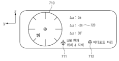
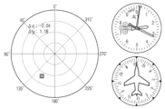
- FIGS. 7A and 7B are drawings for explaining guide information displayed on a user operation device according to one embodiment.
- Figure 8 is a block diagram illustrating the configuration of an aircraft according to one embodiment.
- aircraft may refer to a vehicle or machine with wings that can fly in the air.
- the aircraft may refer to a manned aircraft or an unmanned aircraft.
- the aircraft may refer to an aircraft that is directly piloted by a pilot on board or operated by a program that automatically/semi-automatically controls the flight from the ground without a pilot on board.
- the aircraft may correspond to urban air mobility (UAM).
- UAM urban air mobility
- a "marker” may be an object displayed to guide a landing point of an aircraft.
- the marker may be installed within an airfield where an aircraft takes off and lands.
- the marker may be for identifying a vertiport for urban air traffic to take off and land.
- the marker may be installed in a preset shape.
- the preset shape may be a shape that complies with standard specifications.
- FIG. 1a is a conceptual diagram illustrating a method of operating an aircraft for landing using a marker, according to one embodiment.
- the aircraft (10) can capture a marker (20) for guiding a landing point through an image capturing device within the aircraft (10) and obtain an image including the marker (20).
- the aircraft (10) can provide guide information to the user based on a marker (20) recognized within the captured image.
- the guide information may include relative position information and direction information between the center point of the marker (20) and the center point of the aircraft (10).
- the relative position information may include relative distance information in the x-axis direction and the y-axis direction derived from a two-dimensional image captured by an image capturing device.
- the relative position information may include relative altitude information on which the aircraft (10) is located with respect to the actual plane on which the marker (20) is located.
- the guide information may include guide line information that enables the aircraft (10) to land precisely based on relative position information and direction information.
- FIG. 1b is a drawing for explaining parameters used when calculating a relative pose between an aircraft (10) and a marker (20), according to one embodiment.
- a marker (20) is positioned on an actual plane at a point where an aircraft (10) lands, and a relative position between the marker (20) and the aircraft (10) can be calculated based on a distance between the center of the aircraft (10) and the center of the marker (20).
- the relative position can be expressed by a relative distance on a two-dimensional plane and a relative altitude of the aircraft (10) with respect to the actual plane.
- the direction information of the aircraft (10) with respect to the marker (20) can be calculated by the angle between a line connecting the center of the marker (20) and the center of the aircraft (10) and a predetermined axis.
- Figure 2 is a flow chart showing an operation method of an aircraft (10) according to one embodiment.
- the aircraft (10) can obtain at least one image in which a marker (20) for guiding the landing point of the aircraft (10) is captured through an image capturing device.
- step S220 the aircraft (10) can recognize the marker (20) based on the shape of the marker (20) within at least one image.
- the aircraft (10) can asymmetrically segment the marker (20) based on the shape of the marker (20) within at least one image. Specifically, the aircraft (10) can recognize the marker (20) by segmenting it into a first symbol for calculating the coordinates of the landing point and a second symbol that serves as a reference for estimating relative pose information.
- the aircraft (10) can recognize the marker (20) in at least one image using a marker recognition model.
- the marker recognition model may be a model that recognizes the marker (20) using a histogram-based image binarization algorithm.
- the marker recognition model may analyze the histogram of the image to determine an optimal threshold value for binarizing the image.
- the threshold value may be a reference value for distinguishing the marker (20) and may be a value for separating the pixels corresponding to the area of the marker (20) and the pixels corresponding to the area other than the marker (20).
- the marker recognition model may binarize the image based on the threshold value.
- the marker recognition model may be a learning model that recognizes the marker (20) from an image in which the marker (20) is captured. In the marker recognition model, when an image in which the marker (20) is captured is input as an input value, the result of recognizing the marker (20) may be output as an output value.
- the marker recognition model can divide the captured image into a grid, and set the area around the marker as a filtering area based on the presence or absence of the marker in each grid cell.
- the marker recognition model can recognize the marker (20) by using a histogram-based image binarization algorithm for the filtering area. By setting the filtering area, the range to which the binarization algorithm is applied can be reduced, and the influence of illumination changes that may occur when performing binarization can be reduced.
- the marker recognition model can extract an area within a preset range including the marker (20) within the captured image as a filtering area.
- the area within the preset range can be a minimum area including a symbol within the marker (20).
- the marker recognition model can asymmetrically divide the marker (20) and recognize a first symbol and a second symbol based on the result of applying a histogram-based image binarization algorithm to the filtering area.
- the first symbol is a symbol for calculating the coordinates of the landing point of the aircraft (10)
- the second symbol can be a symbol that serves as a reference for estimating relative pose information. The process of recognizing the marker (20) is described in FIG. 3.
- the aircraft (10) can recognize a marker (20) located at the landing point through an imaging device.
- the imaging device can be an infrared (IR) camera to support precision landing of the aircraft (10) even at night or under low visibility conditions.
- the infrared (IR) camera can recognize an IR sensor attached to a marker (20) located at the landing point.
- the aircraft (10) can estimate relative pose information including relative position information and direction information between the marker (20) and the aircraft (10) based on the result of recognizing the marker (20).
- the relative position information between the marker (20) and the aircraft (10) can include relative distance information and relative altitude information between the marker (20) and the aircraft (10).
- the aircraft (10) can calculate the length of the second symbol within the image plane based on pixel information of at least one image.
- the aircraft (10) can calculate relative distance information based on a ratio of the actual length of the second symbol and the length of the second symbol within the image plane. A process of calculating relative distance information is described in FIG. 4.
- the aircraft (10) can calculate relative altitude information based on the ratio of the actual width of the second symbol and the width within the image plane of the second symbol and the focal length of the imaging device.
- the process of calculating relative altitude information is described in Fig. 5.
- the aircraft (10) can calculate direction information based on the angle between the first axis from the center of the second symbol to the center of the first symbol and the second axis from the center of the first symbol to the center of the aircraft (10).
- the process of calculating direction information is described in Fig. 6.
- step S240 the aircraft (10) can provide guide information to guide the aircraft (10) to land at a landing point based on relative pose information.
- the aircraft (10) can visually display relative position information and direction information. Specifically, the aircraft (10) can display an expected path of the aircraft (10) based on the relative position information and direction information. In addition, the aircraft (10) can display an expected path of the aircraft (10) based on at least one of the relative position information, direction information, the size and shape of the aircraft (10), and external environmental factors around the aircraft (10). Additionally, the aircraft (10) can display an expected path of the aircraft (10) using a navigation system and a control algorithm.
- the aircraft (10) can adjust and display the size of at least one of a model representing a landing point and a model of the aircraft (10) based on at least one of relative position information and direction information.
- FIG. 3 is a drawing for explaining a process of recognizing a marker (20) and estimating relative pose information according to one embodiment.
- the marker (20) may be configured as a polygon.
- the sub-symbols divided from the marker (20) may be symmetrical or asymmetrical to each other.
- the relative position information or direction information of the aircraft (10) with respect to the marker (20) can be easily calculated.
- a processor within an aircraft (10) can recognize a marker (20) based on at least one image captured by an image capturing device. Based on the result of recognizing the marker (20), the processor can estimate relative pose information between the marker (20) and the aircraft (10).
- the processor can detect a first symbol (301) from the marker (20).
- the first symbol (301) may be a symbol for calculating coordinates of a landing point of the aircraft (10).
- the number of line segments constituting the first symbol (301) may be greater than the number of line segments constituting the second symbol (302).
- the processor can select a shape with a maximum area from a polygon corresponding to the first symbol.
- the shape with a maximum area may be a circle.
- the processor can calculate the center of the circle.
- steps S310 to S314 and the operations of steps S320 to S324 may be performed simultaneously or sequentially.
- step S330 the processor can estimate force information using the center of the circle and the center of the rectangle.
- the process of estimating force information is described in FIGS. 4 to 6.
- FIG. 4 is a drawing for explaining a process of calculating the relative distance between a marker (20) and an aircraft (10) according to one embodiment.
- Image (410) of Fig. 4 represents an image plane captured by an imaging device, and image (420) of Fig. 4 represents an actual plane at the landing point of the aircraft (10).
- a processor within the aircraft (10) can calculate a length (l') within the image plane of the second symbol (302) based on pixel information of the image (410). Additionally, the processor can calculate a distance from the center of the first symbol (301) to the x-axis in the image (410) as ⁇ y'.
- the processor can calculate relative distance information between the marker (20) and the aircraft (10) based on a ratio of the actual length (l) of the second symbol (302) and the length (l') of the second symbol (302) within the image plane. Specifically, the processor can calculate ⁇ y, which is a distance from the center of the first symbol (301) to the x-axis in the actual plane, by mathematical expression 1.
- FIG. 5 is a drawing for explaining a process of calculating the relative altitude between a marker (20) and an aircraft (10) according to one embodiment.
- the object (410) represents an image capturing device
- the plane (520) represents an image plane
- the plane (530) represents an actual plane at the landing point of the aircraft (10).
- the focal length (f) may represent the distance from the imaging device to the image plane (520)
- the altitude (h) may represent the distance from the imaging device to the actual plane (530).
- the relationship between the distance (d') within the image plane (520) and the distance (d) within the actual plane (530) is as shown in mathematical expression 2.
- the processor in the aircraft (10) can calculate relative altitude information based on the ratio of the actual width (A) of the second symbol and the width (A') of the second symbol within the image plane and the focal length (f) of the image capturing device. Specifically, the processor can calculate relative altitude information by mathematical expression 3.
- FIG. 6 is a drawing for explaining a process of calculating the direction between a marker (20) and an aircraft (10) according to one embodiment.
- the processor in the aircraft (10) can calculate direction information based on the angle between the first axis (610) that runs from the center of the second symbol (302) to the center of the first symbol (301) and the second axis (620) that runs from the center of the first symbol (301) to the center of the aircraft (10).
- the range of the ⁇ value representing the direction information can exceed -180 degrees and be within 180 degrees.
- FIGS. 7A and 7B are drawings for explaining guide information displayed on a user operation device according to one embodiment.
- the aircraft (10) can visually display relative position information and direction information.
- a user operating device in the aircraft (10) can display an instrument panel interface (710) that reflects relative position information and direction information between the marker (20) and the aircraft (10).
- a model (711) of the aircraft (10) and a model (712) of the marker (20) can be displayed on the instrument panel interface (710), and the model (711) of the aircraft (10) and the model (712) of the marker (20) can be displayed in consideration of directionality.
- the user operating device can reflect relative position information and direction information on the instrument panel interface (710) in real time as the aircraft (10) moves.
- the user operating device can visually display relative position information and direction information. Specifically, as the aircraft (10) gets closer to the marker (20), the size of the model (712) of the marker (20) on the instrument panel interface (710) can be displayed to become larger. In this case, the size of the model (711) of the aircraft (10) can also be displayed to become larger.
- the user operating device may display numerical information (720) for the aircraft (10) to land at a landing point.
- the numerical information (720) may include relative distance information ( ⁇ x, ⁇ y) and direction information ( ⁇ ) calculated in two dimensions.
- the user operation device can display the expected path of the aircraft (10) based on the relative position information and direction information.
- the aircraft (10) can display the expected path of the aircraft (10) based on at least one of the relative position information, direction information, the size and shape of the aircraft (10), and external environmental factors around the aircraft (10). Additionally, the aircraft (10) can display the expected path of the aircraft (10) using a navigation system and a control algorithm.
- the user operating device can display an instrument panel interface (730) reflecting relative position information and direction information. Specifically, the user operating device can display a model of an aircraft (10) reflecting relative position information and direction information centered on a marker (20) on the instrument panel interface (730).
- the user operating device can display visual information (740) and direction information (750) of the aircraft (10) as separate interfaces.
- Fig. 8 is a block diagram illustrating the configuration of an aircraft (10) according to one embodiment.
- the aircraft (10) may include a communication device (810), an image capturing device (820), a user operating device (830), a memory (840), and a processor (850).
- a communication device (810) may include a communication device (810), an image capturing device (820), a user operating device (830), a memory (840), and a processor (850).
- the aircraft (10) may be implemented with more components than the illustrated components, and may be implemented with fewer components than the illustrated components.
- the aircraft (10) illustrated in FIG. 8 may correspond to the aircraft (10) described in FIGS. 1 to 7b in the same manner.
- the communication device (810) can perform communication with an external device.
- the communication device (810) can perform communication with an external device by being connected to a network by wire or wirelessly.
- the external device can be an electronic device.
- the communication device (810) may include a communication module that supports one of various wired and wireless communication methods.
- the communication module may be a short-range communication module or a wired communication module.
- the image capturing device (820) can acquire image frames such as still images or moving images in a capturing mode. Images captured by the image capturing device (820) can be processed by the processor (850).
- the image capturing device (820) can be a camera. A plurality of cameras can be installed in the aircraft (10).
- Image frames processed in the video capturing device (820) can be stored in memory (840) or transmitted externally through a communication device (810).
- the user operating device (830) may mean a device that receives a signal or input from a user to control the aircraft (10).
- the processor (850) can control the user operation device (830) to generate and output a user interface screen for receiving a predetermined command or signal from a user.
- the user operation device (830) can include an input device for receiving an input for controlling the operation of the aircraft (10) and an output device for displaying information such as the operation of the aircraft (10) and the status of the aircraft (10).
- the user operation device (830) can include an operation panel for receiving a user input, a display panel for displaying a screen, etc.
- the input device may include devices capable of receiving various forms of user input, such as a touch screen or a microphone.
- the output device may include, for example, a display panel or a speaker.
- the user operation device (830) is not limited thereto and may include devices that support various input/output.
- the memory (840) can store at least one program for executing an operation method of the aircraft (10) that recognizes a marker (20) based on an image acquired through an image capturing device (820), estimates relative pose information of the aircraft (10) with respect to the marker (20) based on a result of recognizing the marker (20), and provides guide information for guiding the landing of the aircraft (10).
- the at least one program stored in the memory (840) can be classified into a plurality of modules according to function.
- the processor (850) controls the overall operation of the aircraft (10) and may include at least one processor, such as a CPU.
- the processor (850) may include at least one specialized processor corresponding to each function, or may be a processor integrated into one.
- the processor (850) may execute a program stored in the memory (840), read data or a file stored in the memory (840), or store a new file in the memory (840). In addition, the processor (850) may execute instructions stored in the memory (840).
- the video recording device (820) can capture a marker (20) for guiding the landing point of the aircraft (10) and obtain at least one image.
- the processor (850) can recognize the marker (20) based on the shape of the marker (20) within at least one image.
- the processor (850) may asymmetrically segment the marker (20) based on the shape of the marker (20) within at least one image. Specifically, the processor (850) may recognize the marker (20) by segmenting it into a first symbol for calculating the coordinates of the landing point and a second symbol that serves as a reference for estimating relative pose information.
- the processor (850) can recognize a sensor attached to a marker through an image capturing device (820).
- the processor (850) can recognize the marker (20) in at least one image using a marker recognition model.
- the marker recognition model may be a model that recognizes the marker (20) using a histogram-based image binarization algorithm.
- the marker recognition model may analyze the histogram of the image to determine an optimal threshold value for binarizing the image.
- the threshold value may be a reference value for distinguishing the marker (20) and may be a value for separating the pixel corresponding to the area of the marker (20) and the pixel corresponding to the area other than the marker (20).
- the marker recognition model may binarize the image based on the threshold value.
- the marker recognition model may be a learning model that recognizes the marker (20) from an image in which the marker (20) is captured. In the marker recognition model, when an image in which the marker (20) is captured is input as an input value, the result of recognizing the marker (20) may be output as an output value.
- a marker recognition model can divide a captured image into a grid, and set the area around a marker as a filtering area based on the presence or absence of a marker in each grid cell.
- the marker recognition model can recognize a marker (20) by using a histogram-based image binarization algorithm for the filtering area.
- the range to which the binarization algorithm is applied can be reduced, and the influence of illumination changes that may occur when performing binarization can be reduced.
- the marker recognition model can extract a surrounding area including a marker (20) within a captured image as a filtering area.
- the marker recognition model can asymmetrically divide the marker (20) and recognize a first symbol and a second symbol based on the result of applying a histogram-based image binarization algorithm to the filtering area.
- the first symbol can be a symbol for calculating the coordinates of the landing point of the aircraft (10)
- the second symbol can be a symbol that serves as a reference for estimating relative pose information.
- the processor (850) can estimate relative pose information including relative position information and direction information between the marker (20) and the aircraft (10) based on the result of recognizing the marker (20).
- the relative position information between the marker (20) and the aircraft (10) can include relative distance information and relative altitude information between the marker (20) and the aircraft (10).
- the processor (850) can calculate the length of the second symbol within the image plane based on pixel information of at least one image.
- the processor (850) can calculate relative distance information based on a ratio of the actual length of the second symbol and the length of the second symbol within the image plane.
- the processor (850) can calculate relative elevation information based on a ratio of the actual width of the second symbol to the width within the image plane of the second symbol and the focal length of the image capturing device (820).
- the processor (850) can calculate direction information based on the angle between a first axis from the center of the second symbol to the center of the first symbol and a second axis from the center of the first symbol to the center of the aircraft (10).
- the processor (850) can provide guide information to guide the aircraft (10) to land at a landing point based on relative pose information.
- the user operation device (830) can visually display relative position information and direction information. Specifically, the user operation device (830) can display an expected path of the aircraft (10) based on the relative position information and direction information. The user operation device (830) can display an expected path of the aircraft (10) based on at least one of the relative position information, direction information, the size and shape of the aircraft (10), and external environmental factors around the aircraft (10). Additionally, the user operation device (830) can display an expected path of the aircraft (10) using a navigation system and a control algorithm.
- the user operation device (830) can adjust and display the size of at least one of a model representing a landing point and a model of an aircraft (10) based on at least one of relative position information and direction information.
- the aircraft (10) described in the present disclosure may be implemented by hardware components, software components, and/or a combination of hardware components and software components.
- the present disclosure may be provided in the form of a computer program stored in a computer-readable storage medium so as to perform the operating method of the aircraft (10).
- the present disclosure may be written as a program that can be executed on a computer, and may be implemented in a general-purpose digital computer that operates such a program using a computer-readable storage medium.
- Such computer-readable storage media may be read-only memory (ROM), random-access memory (RAM), flash memory, CD-ROMs, CD-Rs, CD+Rs, CD-RWs, CD+RWs, DVD-ROMs, DVD-Rs, DVD+Rs, DVD-RWs, DVD+RWs, DVD-RAMs, BD-ROMs, BD-Rs, BD-R LTHs, BD-REs, magnetic tape, floppy disks, magneto-optical data storage devices, optical data storage devices, hard disks, solid-state disks (SSDs), and any device capable of storing instructions or software, related data, data files, and data structures, or providing instructions or software, related data, data files, and data structures to a processor or a computer so that the processor or the computer may execute the instructions.
- ROM read-only memory
- RAM random-access memory
- flash memory CD-ROMs, CD-Rs, CD+Rs, CD-RWs, CD+RWs, DVD-ROMs,
Landscapes
- Engineering & Computer Science (AREA)
- Physics & Mathematics (AREA)
- General Physics & Mathematics (AREA)
- Multimedia (AREA)
- Theoretical Computer Science (AREA)
- Aviation & Aerospace Engineering (AREA)
- Remote Sensing (AREA)
- Computer Vision & Pattern Recognition (AREA)
- Acoustics & Sound (AREA)
- Mechanical Engineering (AREA)
- Traffic Control Systems (AREA)
Abstract
본 발명의 실시예에 따른 비행체의 동작 방법은, 영상 촬영 장치를 통해 비행체의 착륙 지점을 가이드 하기 위한 마커가 촬영된 적어도 하나의 이미지를 획득하는 단계; 상기 적어도 하나의 이미지 내에서 상기 마커의 형상에 기초하여, 상기 마커를 인식하는 단계; 상기 마커를 인식한 결과에 기초하여, 상기 마커와 상기 비행체 간의 상대적 위치 정보 및 방향 정보를 포함하는 상대적 포즈 정보를 추정하는 단계; 및 상기 상대적 포즈 정보에 기초하여, 상기 비행체가 상기 착륙 지점에 착륙을 가이드 하는 가이드 정보를 제공하는 단계를 포함한다.
Description
비행체 및 비행체의 동작 방법에 관한 것이다.
도심항공교통(UAM: Urban Air Mobility)은 수직이착륙이 가능한 개인 항공기 중 하나로, 하늘을 새로운 이동 통로로 이용할 수 있어 도심에서의 이동 효율성을 극대화한 차세대 모빌리티의 해결책으로 떠오르고 있다.
도심항공교통은 별도의 이착륙 시설이 필요하며, 이착륙 시설에 안전하게 접근하고 정밀하게 착륙을 할 수 있도록 하는 기술이 요구된다.
본원 발명은 과학기술정보통신부의 SA-VINS: 실내 창고의 재고 관리를 위한 항공 로봇의 스마트 자율 항법 시스템 개발(과제고유번호: 1711191634, 과제번호: 2021R1G1A1095335, 연구사업명: 개인기초연구(과기정통부), 과제관리기관: 한국연구재단, 과제수행기관: 경북대학교, 연구기간: 2023.03.01 ~ 2024.02.29)의 일환으로 수행한 연구로부터 도출된 것이다.
또한, 본원 발명은 교육부의 3단계산학연협력선도대학육성사업(LINC3.0)(0.5)(과제고유번호: 1345370628, 과제번호: LINC3.0-2023-9, 연구사업명: 산학협력고도화지원, 과제관리기관: 한국연구재단, 과제수행기관: 경북대학교, 연구기간: 2023.03.01 ~ 2024.02.29)의 일환으로 수행한 연구로부터 도출된 것이다.
한편, 본 발명의 모든 측면에서 과제 제공 주체인 한국 정부의 재산 이익은 없다.
비행체가 착륙 지점에 안전하게 접근하고 정밀하게 착륙할 수 있도록 가이드를 제공하고자 한다. 특히, 도심항공교통의 이착륙 비행장인 버티포트(vertiport)에서 도심항공교통이 정밀 착륙을 할 수 있도록 하고자 한다.
일측에 따르면, 영상 촬영 장치를 통해 비행체의 착륙 지점을 가이드 하기 위한 마커가 촬영된 적어도 하나의 이미지를 획득하는 단계; 상기 적어도 하나의 이미지 내에서 상기 마커의 형상에 기초하여, 상기 마커를 인식하는 단계; 상기 마커를 인식한 결과에 기초하여, 상기 마커와 상기 비행체 간의 상대적 위치 정보 및 방향 정보를 포함하는 상대적 포즈 정보를 추정하는 단계; 및 상기 상대적 포즈 정보에 기초하여, 상기 비행체가 상기 착륙 지점에 착륙을 가이드 하는 가이드 정보를 제공하는 단계를 포함하는, 비행체의 동작 방법이 제공된다.
일실시예에 따르면, 상기 마커를 인식하는 단계는, 상기 적어도 하나의 이미지 내에서 상기 마커의 형상에 기초하여, 상기 마커를 비대칭적으로 분할하여, 상기 비행체의 착륙 지점의 좌표를 산출하기 위한 제1 심볼과 상기 상대적 포즈 정보의 추정을 위해 기준이 되는 제2 심볼로 인식하는 단계를 포함할 수 있다.
일실시예에 따르면, 상기 마커를 인식하는 단계는, 상기 적어도 하나의 이미지 내에서 마커를 포함한 주변 영역을 필터링 영역으로 추출하고, 상기 필터링 영역에 대해 이진화 알고리즘을 적용한 결과에 기초하여, 상기 제1 심볼과 상기 제2 심볼을 인식하는 단계를 포함할 수 있다.
일실시예에 따르면, 상기 마커를 인식하는 단계는, 상기 영상 촬영 장치를 통해 상기 착륙 지점의 주변에 위치한 조명 장치를 인식하는 단계를 더 포함할 수 있다.
일실시예에 따르면, 상기 마커와 상기 비행체 간의 상대적 위치 정보는, 상기 마커와 상기 비행체 간의 상대적 거리 정보 및 상대적 고도 정보를 포함할 수 있다.
일실시예에 따르면, 상기 상대적 포즈 정보를 추정하는 단계는, 상기 적어도 하나의 이미지의 픽셀 정보에 기초하여, 상기 제2 심볼의 이미지 평면 내 길이를 산출하는 단계; 및 상기 제2 심볼의 실제 길이와 상기 제2 심볼의 이미지 평면 내 길이의 비율에 기초하여, 상기 상대적 거리 정보를 산출하는 단계를 포함할 수 있다.
일실시예에 따르면, 상기 상대적 포즈 정보를 추정하는 단계는, 상기 제2 심볼의 실제 넓이와 상기 제2 심볼의 이미지 평면 내 넓이의 비율 및 상기 영상 촬영 장치의 초점 거리에 기초하여, 상기 상대적 고도 정보를 산출하는 단계를 포함할 수 있다.
일실시예에 따르면, 상기 상대적 포즈 정보를 추정하는 단계는, 상기 제2 심볼의 중심에서 상기 제1 심볼의 중심으로 향하는 제1 축과 상기 제1 심볼의 중심에서 상기 비행체의 중심으로 향하는 제2 축 간의 각도에 기초하여 상기 방향 정보를 산출하는 단계를 포함할 수 있다.
일실시예에 따르면, 상기 상대적 포즈 정보에 기초하여, 상기 가이드 정보를 제공하는 단계는, 상기 상대적 위치 정보 및 상기 방향 정보를 시각적으로 표시하는 단계를 포함할 수 있다.
일실시예에 따르면, 상기 가이드 정보를 제공하는 단계는, 상기 상대적 위치 정보 및 상기 방향 정보에 기초하여, 상기 비행체의 예상 경로를 표시하는 단계를 더 포함할 수 있다.
일실시예에 따르면, 상기 상대적 포즈 정보에 기초하여, 상기 가이드 정보를 제공하는 단계는, 상기 상대적 위치 정보 및 상기 방향 정보 중 적어도 하나에 기초하여, 상기 착륙 지점을 나타내는 모형 및 상기 비행체의 모형 중 적어도 하나의 크기를 조절하여 표시하는 단계를 포함할 수 있다.
다른 일측에 따르면, 통신 장치; 영상 촬영 장치; 사용자 조작 장치; 프로세서; 및 상기 프로세서에 의해 실행 가능한 명령어들을 저장하는 메모리를 포함하고, 상기 프로세서는, 상기 명령어들을 실행함으로써, 상기 영상 촬영 장치를 통해 비행체의 착륙 지점을 가이드 하기 위한 마커가 촬영된 적어도 하나의 이미지를 획득하고, 상기 적어도 하나의 이미지 내에서 상기 마커의 형상에 기초하여, 상기 마커를 인식하고, 상기 마커를 인식한 결과에 기초하여, 상기 마커와 상기 비행체 간의 상대적 위치 정보 및 방향 정보를 포함하는 상대적 포즈 정보를 추정하고, 상기 상대적 포즈 정보에 기초하여, 상기 비행체가 상기 착륙 지점에 착륙을 가이드 하는 가이드 정보를 제공하는, 비행체가 제공된다.
일실시예에 따르면, 상기 프로세서는, 상기 명령어들을 실행함으로써, 상기 적어도 하나의 이미지 내에서 상기 마커의 형상에 기초하여, 상기 마커를 비대칭적으로 분할하여, 상기 비행체의 착륙 지점의 좌표를 산출하기 위한 제1 심볼과 상기 상대적 포즈 정보의 추정을 위해 기준이 되는 제2 심볼로 인식할 수 있다.
일실시예에 따르면, 상기 프로세서는, 상기 명령어들을 실행함으로써, 상기 적어도 하나의 이미지의 픽셀 정보에 기초하여, 상기 제2 심볼의 이미지 평면 내 길이를 산출하고, 상기 제2 심볼의 실제 길이와 상기 제2 심볼의 이미지 평면 내 길이의 비율에 기초하여, 상대적 거리 정보를 산출하고, 상기 제2 심볼의 실제 넓이와 상기 제2 심볼의 이미지 평면 내 넓이의 비율 및 상기 영상 촬영 장치의 초점 거리에 기초하여, 상대적 고도 정보를 산출할 수 있다.
일실시예에 따르면, 상기 프로세서는, 상기 명령어들을 실행함으로써, 상기 제2 심볼의 중심에서 상기 제1 심볼의 중심으로 향하는 제1 축과 상기 제1 심볼의 중심에서 상기 비행체의 중심으로 향하는 제2 축 간의 각도에 기초하여 상기 방향 정보를 산출할 수 있다.
일실시예에 따르면, 상기 프로세서는, 상기 명령어들을 실행함으로써, 상기 사용자 조작 장치를 통해 상기 상대적 위치 정보 및 상기 방향 정보를 시각적으로 표시할 수 있다.
또 다른 일측에 따르면, 비행체의 동작 방법을 실행시키기 위해 컴퓨터 판독 가능 저장 매체에 저장된 컴퓨터 프로그램에 있어서, 상기 비행체의 동작 방법은, 영상 촬영 장치를 통해 비행체의 착륙 지점을 가이드 하기 위한 마커가 촬영된 적어도 하나의 이미지를 획득하는 단계; 상기 적어도 하나의 이미지 내에서 상기 마커의 형상에 기초하여, 상기 마커를 인식하는 단계; 상기 마커를 인식한 결과에 기초하여, 상기 마커와 상기 비행체 간의 상대적 위치 정보 및 방향 정보를 포함하는 상대적 포즈 정보를 추정하는 단계; 및 상기 상대적 포즈 정보에 기초하여, 상기 비행체가 상기 착륙 지점에 착륙을 가이드 하는 가이드 정보를 제공하는 단계를 포함하는, 컴퓨터 판독 가능 저장 매체에 저장된 컴퓨터 프로그램이 제공된다.
비행체가 착륙 지점에 안전하게 접근하고 정밀하게 착륙할 수 있도록 가이드를 제공할 수 있다. 특히, 도심항공교통의 이착륙 비행장인 버티포트(vertiport)에서 도심항공교통이 정밀 착륙을 할 수 있도록 유도할 수 있다.
도심항공교통이 버티포트에서 안전하게 이착륙을 할 수 있도록 함으로써, 도심 내에서 접근성을 확보할 수 있다.
또한, 도심항공교통이 배터리 충전, 승객 탑승, 턴어라운드 시간 단축 등의 서비스 편의를 향상시킬 수 있다.
본 개시는, 다음의 자세한 설명과 그에 수반되는 도면들의 결합으로 쉽게 이해될 수 있으며, 참조 번호(reference numerals)들은 구조적 구성요소(structural elements)를 의미한다.
도 1a는 일실시예에 따라, 마커를 이용하여 착륙하기 위한 비행체의 동작 방법을 설명하기 위한 개념도이다.
도 1b는 일실시예에 따라, 비행체와 마커 간의 상대적 포즈를 산출할 때 이용되는 파라미터를 설명하기 위한 도면이다.
도 2는 일실시예에 따라, 비행체의 동작 방법을 나타낸 흐름도이다.
도 3은 일실시예에 따라, 마커를 인식하고, 상대적 포즈 정보를 추정하는 과정을 설명하기 위한 도면이다.
도 4는 일실시예에 따라, 마커와 비행체 간의 상대적 거리를 산출하는 과정을 설명하기 위한 도면이다.
도 5는 일실시예에 따라, 마커와 비행체 간의 상대적 고도를 산출하는 과정을 설명하기 위한 도면이다.
도 6은 일실시예에 따라, 마커와 비행체 간의 방향을 산출하는 과정을 설명하기 위한 도면이다.
도 7a 및 도 7b은 일실시예에 따라, 사용자 조작 장치에 표시되는 가이드 정보를 설명하기 위한 도면이다.
도 8은 일실시예에 따라, 비행체의 구성을 도시한 블록도이다.
이하에서는 도면을 참조하여 다양한 실시예들을 상세히 설명한다. 이하에서 설명되는 실시예들은 여러 가지 상이한 형태로 변형되어 실시될 수도 있다. 실시예들의 특징을 보다 명확히 설명하기 위하여 이하의 실시예들이 속하는 기술분야에서 통상의 지식을 가진 자에게 널리 알려져 있는 사항들에 관해서 자세한 설명은 생략한다.
한편, 본 명세서에서 어떤 구성이 다른 구성과 "연결"되어 있다고 할 때, 이는 '직접적으로 연결'되어 있는 경우 뿐 아니라, '그 중간에 다른 구성을 사이에 두고 연결'되어 있는 경우도 포함한다. 또한, 어떤 구성이 다른 구성을 "포함"한다고 할 때, 이는 특별히 반대되는 기재가 없는 한, 그 외 다른 구성을 제외하는 것이 아니라 다른 구성을 더 포함할 수도 있다는 것을 의미한다.
또한, 본 명세서에서 사용되는 '제 1' 또는 '제 2' 등과 같이 서수를 포함하는 용어는 다양한 구성 요소들을 설명하는데 사용할 수 있지만, 상기 구성 요소들은 상기 용어들에 의해 한정되어서는 안 된다. 상기 용어들은 하나의 구성 요소를 다른 구성 요소로부터 구별하는 목적으로만 사용된다.
본 명세서에서, "비행체"는, 공중을 날 수 있는 날개가 달린 탈 것이나 기계를 지칭하는 것일 수 있다. 또한, 비행체는 유인 항공기, 무인 항공기를 의미할 수 있다. 또한, 비행체는 조종사가 직접 탑승하여 조종하거나 조종사가 탑승하지 않고 지상에서 프로그램에 의해 자동/반자동으로 비행을 조종하여 운행되는 항공기를 의미할 수 있다. 또한, 비행체는 도심항공교통(UAM: Urban Air Mobility)에 해당될 수 있다.
본 명세서에서, "마커"는 비행체의 착륙 지점을 가이드 하기 위해 표시된 객체일 수 있다. 마커는 비행체가 이착륙하는 비행장 내에 설치될 수 있다. 마커는 도심항공교통이 이착륙하기 위한 버티포트를 식별하기 위한 것일 수 있다. 마커는 미리 설정된 형상으로 설치될 수 있다. 여기서, 미리 설정된 형상은 표준 규격에 부합되는 형상일 수도 있다.
이하에서는, 전술한 본 발명의 구체적인 실시예를 도 1a 내지 도 8을 참조하여 설명한다.
도 1a는 일실시예에 따라, 마커를 이용하여 착륙하기 위한 비행체의 동작 방법을 설명하기 위한 개념도이다.
도 1a를 참고하면, 비행체(10)는 비행체(10) 내의 영상 촬영 장치를 통해 착륙 지점을 가이드 하기 위한 마커(20)를 촬영하고, 마커(20)가 포함된 이미지를 획득할 수 있다.
비행체(10)가 착륙 지점에 안전하게 접근하고 착륙을 할 수 있도록 하기 위해, 비행체(10)는 촬영된 이미지 내에서 인식된 마커(20)에 기초하여, 가이드 정보를 사용자에게 제공할 수 있다.
여기서, 가이드 정보는, 마커(20)의 중심점과 비행체(10)의 중심점 간의 상대적 위치 정보 및 방향 정보를 포함할 수 있다. 상대적 위치 정보는, 영상 촬영 장치를 통해 촬영된 2차원 이미지에서 도출된 x축 방향, y축 방향의 상대적 거리 정보를 포함할 수 있다. 또한, 상대적 위치 정보는 마커(20)의 위치하는 실제 평면에 대한 비행체(10)가 위치한 상대적 고도 정보를 포함할 수 있다.
또한, 가이드 정보는, 상대적 위치 정보 및 방향 정보에 따라 비행체(10)가 정밀하게 착륙할 수 있도록 하는 가이드 라인의 정보를 포함할 수 있다.
도 1b는 일실시예에 따라, 비행체(10)와 마커(20) 간의 상대적 포즈를 산출할 때 이용되는 파라미터를 설명하기 위한 도면이다.
도 1b의 이미지(110)을 참고하면, 비행체(10)가 착륙하는 지점의 실제 평면 상에 마커(20)가 위치하며, 마커(20)와 비행체(10) 간의 상대적 위치는 비행체(10)의 중심과 마커(20)의 중심 간의 거리에 기초하여 산출될 수 있다. 상대적 위치는, 2차원 평면 상에서 상대적 거리 및 실제 평면 대비 비행체(10)의 상대적 고도에 의해 표현될 수 있다.
또한, 도 1b의 이미지(120)을 참고하면, 마커(20)의 중심과 비행체(10)의 중심을 잇는 선과 소정의 축 간의 각도에 의해 마커(20)에 대한 비행체(10)의 방향 정보가 산출될 수 있다.
도 2는 일실시예에 따라, 비행체(10)의 동작 방법을 나타낸 흐름도이다.
도 2를 참고하면, 단계 S210에서, 비행체(10)는 영상 촬영 장치를 통해 비행체(10)의 착륙 지점을 가이드 하기 위한 마커(20)가 촬영된 적어도 하나의 이미지를 획득할 수 있다.
단계 S220에서, 비행체(10)는 적어도 하나의 이미지 내에서 마커(20)의 형상에 기초하여, 마커(20)를 인식할 수 있다.
예를 들면, 비행체(10)는 적어도 하나의 이미지 내에서 마커(20)의 형상에 기초하여, 마커(20)를 비대칭적으로 분할할 수 있다. 구체적으로, 비행체(10)는 착륙 지점의 좌표를 산출하기 위한 제1 심볼과 상대적 포즈 정보의 추정을 위해 기준이 되는 제2 심볼로 분할하여 마커(20)를 인식할 수 있다.
또한, 비행체(10)는 마커 인식 모델을 이용하여, 적어도 하나의 이미지 내에서 마커(20)를 인식할 수 있다. 마커 인식 모델은, 히스토그램 기반의 이미지 이진화 알고리즘을 이용하여, 마커(20)를 인식하는 모델일 수 있다. 예를 들면, 마커 인식 모델은, 이미지의 히스토그램을 분석하여 이미지를 이진화하기 위한 최적의 임계값을 결정할 수 있다. 여기서, 임계값은, 마커(20)를 구분하기 위한 기준값일 수 있으며, 마커(20)의 영역에 대응하는 픽셀과 마커(20)가 아닌 영역에 대응하는 픽셀을 분리하기 위한 값일 수 있다. 마커 인식 모델은, 임계값에 기초하여, 이미지를 이진화할 수 있다. 예를 들면, 마커 인식 모델은, 마커(20)가 촬영된 이미지로부터 마커(20)를 인식하는 학습 모델일 수 있다. 마커 인식 모델에서, 마커(20)가 촬영된 이미지가 입력값으로 입력되면, 마커(20)를 인식한 결과를 출력값으로 출력될 수 있다.
또한, 마커 인식 모델은, 촬영된 이미지를 그리드로 나누고, 각 그리드 셀에서 마커의 존재 여부에 기초하여, 마커 주변을 필터링 영역으로 설정할 수 있다. 마커 인식 모델은 필터링 영역에 대해 히스토그램 기반의 이미지 이진화 알고리즘을 이용하여, 마커(20)를 인식할 수 있다. 필터링 영역을 설정하게 되면, 이진화 알고리즘을 적용하는 범위를 줄일 수 있으며, 이진화를 수행할 때 발생할 수 있는 조명 변화의 영향을 줄일 수 있다.
또한, 마커 인식 모델은, 촬영된 이미지 내에서 마커(20)를 포함한 미리 설정된 범위 내의 영역을 필터링 영역으로 추출할 수 있다. 예를 들면, 미리 설정된 범위 내의 영역은, 마커(20) 내의 심볼을 포함하는 최소 영역일 수 있다. 마커 인식 모델은, 필터링 영역에 대해, 히스토그램 기반의 이미지 이진화 알고리즘을 적용한 결과에 기초하여, 마커(20)를 비대칭적으로 분할하고, 제1 심볼과 제2 심볼을 인식할 수 있다. 제1 심볼은 비행체(10)의 착륙 지점의 좌표를 산출하기 위한 심볼이고, 제2 심볼은 상대적 포즈 정보의 추정을 위한 기준이 되는 심볼일 수 있다. 도 3에서 마커(20)를 인식하는 과정을 설명한다.
또한, 비행체(10)는 영상 촬영 장치를 통해 착륙 지점에 위치한 마커(20)를 인식할 수 있다. 예를 들면, 영상 촬영 장치는, 비행체(10)가 야간 또는 저시정 조건에서도 정밀 착륙을 지원하기 위한 적외선(IR) 카메라일 수 있다. 적외선(IR) 카메라는 착륙 지점에 위치한 마커(20)에 부착된 IR 센서를 인식할 수 있다.
단계 S230에서, 비행체(10)는 마커(20)를 인식한 결과에 기초하여, 마커(20)와 비행체(10) 간의 상대적 위치 정보 및 방향 정보를 포함하는 상대적 포즈 정보를 추정할 수 있다. 여기서, 마커(20)와 비행체(10) 간의 상대적 위치 정보는, 마커(20)와 비행체(10) 간의 상대적 거리 정보 및 상대적 고도 정보를 포함할 수 있다.
예를 들면, 비행체(10)는 적어도 하나의 이미지의 픽셀 정보에 기초하여, 제2 심볼의 이미지 평면 내 길이를 산출할 수 있다. 비행체(10)는 제2 심볼의 실제 길이와 제2 심볼의 이미지 평면 내 길이의 비율에 기초하여, 상대적 거리 정보를 산출할 수 있다. 도 4에서 상대적 거리 정보를 산출하는 과정을 설명한다.
예를 들면, 비행체(10)는 제2 심볼의 실제 넓이와 제2 심볼의 이미지 평면 내 넓이의 비율 및 영상 촬영 장치의 초점 거리에 기초하여, 상대적 고도 정보를 산출할 수 있다. 도 5에서 상대적 고도 정보를 산출하는 과정을 설명한다.
예를 들면, 비행체(10)는 제2 심볼의 중심에서 제1 심볼의 중심으로 향하는 제1 축과 제1 심볼의 중심에서 비행체(10)의 중심으로 향하는 제2 축 간의 각도에 기초하여, 방향 정보를 산출할 수 있다. 도 6에서 방향 정보를 산출하는 과정을 설명한다.
단계 S240에서, 비행체(10)는 상대적 포즈 정보에 기초하여, 비행체(10)가 착륙 지점에 착륙을 가이드 하는 가이드 정보를 제공할 수 있다.
예를 들면, 비행체(10)는 상대적 위치 정보 및 방향 정보를 시각적으로 표시할 수 있다. 구체적으로, 비행체(10)는 상대적 위치 정보 및 방향 정보에 기초하여, 비행체(10)의 예상 경로를 표시할 수 있다. 또한, 비행체(10)는 상대적 위치 정보, 방향 정보, 비행체(10)의 크기와 형태, 및 비행체(10) 주변의 외부 환경 요인 중 적어도 하나에 기초하여, 비행체(10)의 예상 경로를 표시할 수 있다. 추가로, 비행체(10)는 항법 시스템과 제어 알고리즘을 이용하여, 비행체(10)의 예상 경로를 표시할 수 있다.
예를 들면, 비행체(10)는 상대적 위치 정보 및 방향 정보 중 적어도 하나에 기초하여, 착륙 지점을 나타내는 모형 및 비행체(10)의 모형 중 적어도 하나의 크기를 조절하여 표시할 수 있다.
도 3은 일실시예에 따라, 마커(20)를 인식하고, 상대적 포즈 정보를 추정하는 과정을 설명하기 위한 도면이다.
도 1b 및 도 3을 참고하면, 마커(20)는 다각형으로 구성될 수 있다. 마커 (20)를 분할하는 기준선의 위치에 따라, 마커(20)에서 분할된 하위 심볼들은 서로 대칭이거나 비대칭일 수 있다. 서로 비대칭적인 심볼들을 이용하면, 마커(20)에 대한 비행체(10)의 상대적 위치 정보 또는 방향 정보가 용이하게 산출될 수 있다.
비행체(10) 내의 프로세서는, 영상 촬영 장치에서 촬영된 적어도 하나의 이미지에 기초하여, 마커(20)를 인식할 수 있다. 프로세서는 마커(20)를 인식한 결과에 기초하여, 마커(20)와 비행체(10) 간의 상대적 포즈 정보를 추정할 수 있다.
구체적으로, 단계 S310에서, 프로세서는 마커(20)에서 제1 심볼(301)을 검출할 수 있다. 제1 심볼(301)은 비행체(10)의 착륙 지점의 좌표를 산출하기 위한 심볼일 수 있다. 제1 심볼(301)을 구성하는 선분의 수는 제2 심볼(302)을 구성하는 선분의 수보다 클 수 있다. 단계 S312에서, 프로세서는 제1 심볼에 대응하는 다각형에서 최대 면적인 도형을 선택할 수 있다. 예를 들면, 최대 면적인 도형은 원일 수 있다. 단계 S314에서, 프로세서는 원의 중심을 산출할 수 있다.
단계 S320에서, 프로세서는 마커(20)에서 제2 심볼(302)을 검출할 수 있다. 제2 심볼(302)은 상대적 포즈 정보의 추정을 위해 기준이 되는 심볼일 수 있다. 제2 심볼(302)에 대응하는 다각형은 각도가 90도인 것이 특징일 수 있다. 단계 S322에서, 프로세서는, 각도가 90도인 다각형의 특징인 직사각형을 선택할 수 있다. 단계 S324에서, 프로세서는 직사각형의 중심을 산출할 수 있다.
단계 S310 내지 단계 S314의 동작과 단계 S320 내지 단계 S324의 동작은 동시에 수행되거나 순차적으로 수행될 수 있다.
단계 S330에서, 프로세서는 원의 중심과 직사각형의 중심을 이용하여 포스 정보를 추정할 수 있다. 포스 정보를 추정하는 과정은 도 4 내지 도 6에서 설명한다.
도 4는 일실시예에 따라, 마커(20)와 비행체(10) 간의 상대적 거리를 산출하는 과정을 설명하기 위한 도면이다.
도 4의 이미지(410)는 영상 촬영 장치에서 촬영된 이미지 평면을 나타내고, 도 4의 이미지(420)는 비행체(10)가 착륙하는 지점의 실제 평면을 나타낸다.
비행체(10) 내의 프로세서는 이미지(410)의 픽셀 정보에 기초하여, 제2 심볼(302)의 이미지 평면 내 길이(l')를 산출할 수 있다. 또한, 프로세서는 이미지(410)에서 제1 심볼(301)의 중심으로부터 x 축까지의 거리를 △y'로 산출할 수 있다.
프로세서는 제2 심볼(302)의 실제 길이(l)와 제2 심볼(302)의 이미지 평면 내 길이(l')의 비율에 기초하여, 마커(20)와 비행체(10) 간의 상대적 거리 정보를 산출할 수 있다. 구체적으로, 프로세서는 수학식 1에 의해 실제 평면에서 제1 심볼(301)의 중심으로부터 x 축까지의 거리인 △y를 산출할 수 있다.

도 5는 일실시예에 따라, 마커(20)와 비행체(10) 간의 상대적 고도를 산출하는 과정을 설명하기 위한 도면이다.
도 5를 참고하면, 객체(410)는 영상 촬영 장치를 나타내고, 평면(520)은 이미지 평면을 나타내고, 평면(530)은 비행체(10)가 착륙하는 지점의 실제 평면을 나타낸다.
또한, 초점 거리(f)는 영상 촬영 장치로부터 이미지 평면(520)까지의 거리를 나타내고, 고도(h)는 영상 촬영 장치로부터 실제 평면(530)까지의 거리를 나타낼 수 있다. 이미지 평면(520) 내의 거리(d')와 실제 평면(530) 내의 거리(d) 간의 관계는 수학식 2와 같다.

비행체(10) 내의 프로세서는 제2 심볼의 실제 넓이(A)와 제2 심볼의 이미지 평면 내 넓이(A')의 비율 및 영상 촬영 장치의 초점 거리(f)에 기초하여, 상대적 고도 정보를 산출할 수 있다. 구체적으로, 프로세서는 수학식 3에 의해 상대적 고도 정보를 산출할 수 있다.

도 6은 일실시예에 따라, 마커(20)와 비행체(10) 간의 방향을 산출하는 과정을 설명하기 위한 도면이다.
도 6을 참고하면, 비행체(10) 내의 프로세서는 제2 심볼(302)의 중심에서 제1 심볼(301)의 중심으로 향하는 제1 축(610)과 제1 심볼(301)의 중심에서 비행체(10)의 중심으로 향하는 제2 축(620) 간의 각도에 기초하여, 방향 정보를 산출할 수 있다. 여기서, 방향 정보를 나타내는 θ 값의 범위는 -180도를 초과하고 180도 이내일 수 있다.
도 7a 및 도 7b은 일실시예에 따라, 사용자 조작 장치에 표시되는 가이드 정보를 설명하기 위한 도면이다.
비행체(10)는 상대적 위치 정보 및 방향 정보를 시각적으로 표시할 수 있다. 예를 들면, 도 7a에 도시된 바와 같이, 비행체(10) 내의 사용자 조작 장치는 마커(20)와 비행체(10) 간의 상대적 위치 정보 및 방향 정보가 반영된 계기판 인터페이스(710)를 표시할 수 있다. 계기판 인터페이스(710) 상에는 비행체(10)의 모형(711)과 마커(20)의 모형(712)가 표시될 수 있으며, 비행체(10)의 모형(711)과 마커(20)의 모형(712)은 방향성을 고려하여 표시될 수 있다. 또한, 사용자 조작 장치는, 비행체(10)가 움직임에 따라 상대적 위치 정보와 방향 정보를 게기판 인터페이스(710) 상에 실시간으로 반영할 수 있다.
예를 들면, 사용자 조작 장치는 상대적 위치 정보 및 방향 정보를 시각적으로 표시할 수 있다. 구체적으로, 비행체(10)가 마커(20)에 가까워질수록 계기판 인터페이스(710) 상에서 마커(20)의 모형(712) 크기가 점점 커지도록 표시될 수 있다. 이 경우, 비행체(10)의 모형(711) 크기도 점점 커지도록 표시될 수 있다.
또한, 사용자 조작 장치는 비행체(10)가 착륙 지점에 착륙하기 위한 수치 정보(720)를 표시할 수 있다. 예를 들면, 수치 정보(720)는, 2차원 상에서 산출된 상대적 거리 정보(△x, △y) 및 방향 정보(△θ)를 포함할 수 있다.
또한, 사용자 조작 장치는, 상대적 위치 정보 및 방향 정보에 기초하여, 비행체(10)의 예상 경로를 표시할 수 있다. 또한, 비행체(10)는 상대적 위치 정보, 방향 정보, 비행체(10)의 크기와 형태, 및 비행체(10) 주변의 외부 환경 요인 중 적어도 하나에 기초하여, 비행체(10)의 예상 경로를 표시할 수 있다. 추가로, 비행체(10)는 항법 시스템과 제어 알고리즘을 이용하여, 비행체(10)의 예상 경로를 표시할 수 있다.
도 7b를 참고하면, 사용자 조작 장치는 상대적 위치 정보 및 방향 정보가 반영된 계기판 인터페이스(730)를 표시할 수 있다. 구체적으로, 사용자 조작 장치는 마커(20)를 중심으로 상대적 위치 정보 및 방향 정보가 반영된 비행체(10)의 모형을 계기판 인터페이스(730) 상에 표시할 수 있다.
또한, 사용자 조작 장치는 시각 정보(740) 및 비행체(10)의 방향 정보(750)를 별도의 인터페이스로 표시할 수 있다.
도 8은 일실시예에 따라, 비행체(10)의 구성을 도시한 블록도이다.
도 8을 참고하면, 비행체(10)는 통신 장치(810), 영상 촬영 장치(820), 사용자 조작 장치(830), 메모리(840) 및 프로세서(850)를 포함할 수 있다. 그러나, 도시된 구성 요소 모두가 필수 구성 요소인 것은 아니다. 도시된 구성 요소보다 많은 구성 요소에 의해 비행체(10)가 구현될 수 있고, 구보다 적은 요소에 의해 비행체(10)가 구현될 수 있다. 이하, 상기 구성 요소들에 의해 살펴본다. 도 8에 도시된 비행체(10)는 도 1 내지 도 7b에서 설명한 비행체(10)와 동일하게 대응될 수 있다.
통신 장치(810)는 외부 장치와 통신을 수행할 수 있다. 예를 들면, 통신 장치(810)는, 유선 또는 무선으로 네트워크와 연결되어 외부 장치와 통신을 수행할 수 있다. 여기서, 외부 장치는, 전자 장치일 수 있다.
통신 장치(810)는, 다양한 유무선 통신 방법 중 하나를 지원하는 통신 모듈을 포함할 수 있다. 통신 모듈은 근거리 통신 모듈, 유선 통신 모듈일 수 있다.
영상 촬영 장치(820)는 촬영 모드에서 정지 영상 또는 동영상 등의 화상 프레임을 획득할 수 있다. 영상 촬영 장치(820)를 통해 촬영된 이미지는 프로세서(850)를 통해 처리될 수 있다. 예를 들면, 영상 촬영 장치(820)는 카메라일 수 있다. 카메라는 비행체(10) 내에 복수 개가 설치될 수 있다.
영상 촬영 장치(820)에서 처리된 화상 프레임은 메모리(840)에 저장되거나 통신 장치(810)를 통해 외부로 전송될 수 있다.
사용자 조작 장치(830)는 사용자로부터 비행체(10)를 제어하기 위한 신호 또는 입력을 받는 장치를 의미할 수 있다.
프로세서(850)는, 사용자로부터 소정 명령 또는 신호를 입력 받기 위한 사용자 인터페이스 화면을 생성 및 출력하도록 사용자 조작 장치(830)를 제어할 수 있다. 사용자 조작 장치(830)는 비행체(10)의 동작을 제어하는 입력을 수신하기 위한 입력 장치와 비행체(10)의 동작, 비행체(10)의 상태 등의 정보를 표시하기 위한 출력 장치를 포함할 수 있다. 예를 들면, 사용자 조작 장치(830)는 사용자 입력을 수신하는 조작 패널, 화면을 표시하는 디스플레이 패널 등을 포함할 수 있다.
예를 들면, 입력 장치는 터치 스크린, 또는 마이크 등과 같이 다양한 형태의 사용자 입력을 수신할 수 있는 장치들을 포함할 수 있다. 또한, 출력 장치는, 예를 들어, 디스플레이 패널 또는 스피커 등을 포함할 수 있다. 다만, 이에 한정되지 않고 사용자 조작 장치(830)는 다양한 입출력을 지원하는 장치를 포함할 수 있다.
메모리(840)는, 영상 촬영 장치(820)를 통해 획득된 이미지에 기초하여 마커(20)를 인식하고, 마커(20)를 인식한 결과에 기초하여 마커(20)에 대한 비행체(10)의 상대적 포즈 정보를 추정하고, 비행체(10)의 착륙을 가이드 하는 가이드 정보를 제공하는 비행체(10)의 동작 방법을 비행체(10)에서 실행시키기 위한 적어도 하나의 프로그램을 저장할 수 있다. 메모리(840)에 저장된 적어도 하나의 프로그램은 기능에 따라 복수 개의 모듈들로 분류될 수 있다.
프로세서(850)는, 비행체(10)의 전체적인 동작을 제어하며, CPU 등과 같은 적어도 하나의 프로세서를 포함할 수 있다. 프로세서(850)는 각 기능에 대응되는 특화된 프로세서를 적어도 하나 포함하거나, 하나로 통합된 형태의 프로세서일 수 있다.
프로세서(850)는 메모리(840)에 저장된 프로그램을 실행시키거나, 메모리(840)에 저장된 데이터 또는 파일을 읽어오거나, 새로운 파일을 메모리(840)에 저장할 수도 있다. 또한, 프로세서(850)는 메모리(840)에 저장된 명령어들을 실행할 수 있다.
영상 촬영 장치(820)는 비행체(10)의 착륙 지점을 가이드 하기 위한 마커(20)를 촬영하고, 적어도 하나의 이미지를 획득할 수 있다.
프로세서(850)는 적어도 하나의 이미지 내에서 마커(20)의 형상에 기초하여, 마커(20)를 인식할 수 있다.
예를 들면, 프로세서(850)는 적어도 하나의 이미지 내에서 마커(20)의 형상에 기초하여, 마커(20)를 비대칭적으로 분할할 수 있다. 구체적으로, 프로세서(850)는 착륙 지점의 좌표를 산출하기 위한 제1 심볼과 상대적 포즈 정보의 추정을 위해 기준이 되는 제2 심볼로 분할하여 마커(20)를 인식할 수 있다.
또한, 프로세서(850)는 영상 촬영 장치(820)를 통해 마커에 부착된 센서를 인식할 수 있다.
또한, 프로세서(850)는 마커 인식 모델을 이용하여, 적어도 하나의 이미지 내에서 마커(20)를 인식할 수 있다. 마커 인식 모델은, 히스토그램 기반의 이미지 이진화 알고리즘을 이용하여, 마커(20)를 인식하는 모델일 수 있다. 예를 들면, 마커 인식 모델은, 이미지의 히스토그램을 분석하여 이미지를 이진화하기 위한 최적의 임계값을 결정할 수 있다. 여기서, 임계값은, 마커(20)를 구분하기 위한 기준값일 수 있으며, 마커(20)의 영역에 대응하는 픽셀과 마커(20)가 아닌 영역에 대응하는 픽셀을 분리하기 위한 값일 수 있다. 마커 인식 모델은, 임계값에 기초하여, 이미지를 이진화할 수 있다. 예를 들면, 마커 인식 모델은, 마커(20)가 촬영된 이미지로부터 마커(20)를 인식하는 학습 모델일 수 있다. 마커 인식 모델에서, 마커(20)가 촬영된 이미지가 입력값으로 입력되면, 마커(20)를 인식한 결과를 출력값으로 출력될 수 있다.
예를 들면, 마커 인식 모델은, 촬영된 이미지를 그리드로 나누고, 각 그리드 셀에서 마커의 존재 여부에 기초하여, 마커 주변을 필터링 영역으로 설정할 수 있다. 마커 인식 모델은 필터링 영역에 대해 히스토그램 기반의 이미지 이진화 알고리즘을 이용하여, 마커(20)를 인식할 수 있다. 필터링 영역을 설정하게 되면, 이진화 알고리즘을 적용하는 범위를 줄일 수 있으며, 이진화를 수행할 때 발생할 수 있는 조명 변화의 영향을 줄일 수 있다.
예를 들면, 마커 인식 모델은, 촬영된 이미지 내에서 마커(20)를 포함한 주변 영역을 필터링 영역으로 추출할 수 있다. 마커 인식 모델은, 필터링 영역에 대해, 히스토그램 기반의 이미지 이진화 알고리즘을 적용한 결과에 기초하여, 마커(20)를 비대칭적으로 분할하고, 제1 심볼과 제2 심볼을 인식할 수 있다. 제1 심볼은 비행체(10)의 착륙 지점의 좌표를 산출하기 위한 심볼이고, 제2 심볼은 상대적 포즈 정보의 추정을 위한 기준이 되는 심볼일 수 있다.
프로세서(850)는 마커(20)를 인식한 결과에 기초하여, 마커(20)와 비행체(10) 간의 상대적 위치 정보 및 방향 정보를 포함하는 상대적 포즈 정보를 추정할 수 있다. 여기서, 마커(20)와 비행체(10) 간의 상대적 위치 정보는, 마커(20)와 비행체(10) 간의 상대적 거리 정보 및 상대적 고도 정보를 포함할 수 있다.
예를 들면, 프로세서(850)는 적어도 하나의 이미지의 픽셀 정보에 기초하여, 제2 심볼의 이미지 평면 내 길이를 산출할 수 있다. 프로세서(850)는 제2 심볼의 실제 길이와 제2 심볼의 이미지 평면 내 길이의 비율에 기초하여, 상대적 거리 정보를 산출할 수 있다.
예를 들면, 프로세서(850)는 제2 심볼의 실제 넓이와 제2 심볼의 이미지 평면 내 넓이의 비율 및 영상 촬영 장치(820)의 초점 거리에 기초하여, 상대적 고도 정보를 산출할 수 있다.
예를 들면, 프로세서(850)는 제2 심볼의 중심에서 제1 심볼의 중심으로 향하는 제1 축과 제1 심볼의 중심에서 비행체(10)의 중심으로 향하는 제2 축 간의 각도에 기초하여, 방향 정보를 산출할 수 있다.
프로세서(850)는 상대적 포즈 정보에 기초하여, 비행체(10)가 착륙 지점에 착륙을 가이드 하는 가이드 정보를 제공할 수 있다.
예를 들면, 사용자 조작 장치(830)는 상대적 위치 정보 및 방향 정보를 시각적으로 표시할 수 있다. 구체적으로, 사용자 조작 장치(830)는 상대적 위치 정보 및 방향 정보에 기초하여, 비행체(10)의 예상 경로를 표시할 수 있다. 사용자 조작 장치(830)는 상대적 위치 정보, 방향 정보, 비행체(10)의 크기와 형태, 및 비행체(10) 주변의 외부 환경 요인 중 적어도 하나에 기초하여, 비행체(10)의 예상 경로를 표시할 수 있다. 추가로, 사용자 조작 장치(830)는 항법 시스템과 제어 알고리즘을 이용하여, 비행체(10)의 예상 경로를 표시할 수 있다.
예를 들면, 사용자 조작 장치(830)는 상대적 위치 정보 및 방향 정보 중 적어도 하나에 기초하여, 착륙 지점을 나타내는 모형 및 비행체(10)의 모형 중 적어도 하나의 크기를 조절하여 표시할 수 있다.
본 개시에서 설명된 비행체(10)는 하드웨어 구성요소, 소프트웨어 구성요소, 및/또는 하드웨어 구성요소 및 소프트웨어 구성요소의 조합으로 구현될 수 있다. 또한, 본 개시는, 비행체(10)의 동작 방법을 수행할 수 있도록 컴퓨터 판독가능 저장매체에 저장된 컴퓨터 프로그램 형태로 제공될 수 있다. 또한, 본 개시는, 컴퓨터에서 실행될 수 있는 프로그램으로 작성가능하고, 컴퓨터 판독 가능 저장매체를 이용하여 이와 같은 프로그램을 동작시키는 범용 디지털 컴퓨터에서 구현될 수 있다.
이와 같은 컴퓨터 판독 가능 저장매체는 read-only memory (ROM), random-access memory (RAM), flash memory, CD-ROMs, CD-Rs, CD+Rs, CD-RWs, CD+RWs, DVD-ROMs, DVD-Rs, DVD+Rs, DVD-RWs, DVD+RWs, DVD-RAMs, BD-ROMs, BD-Rs, BD-R LTHs, BD-REs, 마그네틱 테이프, 플로피 디스크, 광자기 데이터 저장 장치, 광학 데이터 저장 장치, 하드 디스크, 솔리드-스테이트 디스크(SSD)일 수 있고, 명령어 또는 소프트웨어, 관련 데이터, 데이터 파일, 및 데이터 구조들을 저장할 수 있고, 프로세서나 컴퓨터가 명령어를 실행할 수 있도록 프로세서나 컴퓨터에 명령어 또는 소프트웨어, 관련 데이터, 데이터 파일, 및 데이터 구조들을 제공할 수 있는 어떠한 장치라도 될 수 있다.
이상에서 실시예들에 대하여 상세하게 설명하였지만 본 발명의 권리범위는 이에 한정되는 것은 아니고 다음의 청구범위에서 정의하고 있는 본 발명의 기본 개념을 이용한 기술분야에서 통상의 지식을 가진 자의 여러 변형 및 개량 형태 또한 본 발명의 권리범위에 속한다.
Claims (15)
- 영상 촬영 장치를 통해 비행체의 착륙 지점을 가이드 하기 위한 마커가 촬영된 적어도 하나의 이미지를 획득하는 단계;상기 적어도 하나의 이미지 내에서 상기 마커의 형상에 기초하여, 상기 마커를 인식하는 단계;상기 마커를 인식한 결과에 기초하여, 상기 마커와 상기 비행체 간의 상대적 위치 정보 및 방향 정보를 포함하는 상대적 포즈 정보를 추정하는 단계; 및상기 상대적 포즈 정보에 기초하여, 상기 비행체가 상기 착륙 지점에 착륙을 가이드 하는 가이드 정보를 제공하는 단계를 포함하는, 비행체의 동작 방법.
- 제1항에 있어서,상기 마커를 인식하는 단계는,상기 적어도 하나의 이미지 내에서 상기 마커의 형상에 기초하여, 상기 마커를 비대칭적으로 분할하여, 상기 비행체의 착륙 지점의 좌표를 산출하기 위한 제1 심볼과 상기 상대적 포즈 정보의 추정을 위해 기준이 되는 제2 심볼로 인식하는 단계를 포함하는, 비행체의 동작 방법.
- 제2항에 있어서,상기 마커를 인식하는 단계는,상기 적어도 하나의 이미지 내에서 마커 내의 심볼을 포함한 최소 영역을 필터링 영역으로 추출하고, 상기 필터링 영역에 대해 이진화 알고리즘을 적용한 결과에 기초하여, 상기 제1 심볼과 상기 제2 심볼을 인식하는 단계를 포함하는, 비행체의 동작 방법.
- 제2항에 있어서,상기 마커를 인식하는 단계는,상기 영상 촬영 장치를 통해 상기 마커에 부착된 센서를 인식하는 단계를 더 포함하는, 비행체의 동작 방법.
- 제2항에 있어서,상기 마커와 상기 비행체 간의 상대적 위치 정보는,상기 마커와 상기 비행체 간의 상대적 거리 정보 및 상대적 고도 정보를 포함하는, 비행체의 동작 방법.
- 제5항에 있어서,상기 상대적 포즈 정보를 추정하는 단계는,상기 적어도 하나의 이미지의 픽셀 정보에 기초하여, 상기 제2 심볼의 이미지 평면 내 길이를 산출하는 단계; 및상기 제2 심볼의 실제 길이와 상기 제2 심볼의 이미지 평면 내 길이의 비율에 기초하여, 상기 상대적 거리 정보를 산출하는 단계를 포함하는, 비행체의 동작 방법.
- 제6항에 있어서,상기 상대적 포즈 정보를 추정하는 단계는,상기 제2 심볼의 실제 넓이와 상기 제2 심볼의 이미지 평면 내 넓이의 비율 및 상기 영상 촬영 장치의 초점 거리에 기초하여, 상기 상대적 고도 정보를 산출하는 단계를 포함하는, 비행체의 동작 방법.
- 제2항에 있어서,상기 상대적 포즈 정보를 추정하는 단계는,상기 제2 심볼의 중심에서 상기 제1 심볼의 중심으로 향하는 제1 축과 상기 제1 심볼의 중심에서 상기 비행체의 중심으로 향하는 제2 축 간의 각도에 기초하여 상기 방향 정보를 산출하는 단계를 포함하는, 비행체의 동작 방법.
- 제1항에 있어서,상기 상대적 포즈 정보에 기초하여, 상기 가이드 정보를 제공하는 단계는,상기 상대적 위치 정보 및 상기 방향 정보를 시각적으로 표시하는 단계를 포함하는, 비행체의 동작 방법.
- 제9항에 있어서,상기 가이드 정보를 제공하는 단계는,상기 상대적 위치 정보 및 상기 방향 정보에 기초하여, 상기 비행체의 예상 경로를 표시하는 단계를 더 포함하는, 비행체의 동작 방법.
- 제9항에 있어서,상기 상대적 포즈 정보에 기초하여, 상기 가이드 정보를 제공하는 단계는,상기 상대적 위치 정보 및 상기 방향 정보 중 적어도 하나에 기초하여, 상기 착륙 지점을 나타내는 모형 및 상기 비행체의 모형 중 적어도 하나의 크기를 조절하여 표시하는 단계를 포함하는, 비행체의 동작 방법.
- 통신 장치;영상 촬영 장치;사용자 조작 장치;프로세서; 및상기 프로세서에 의해 실행 가능한 명령어들을 저장하는 메모리를 포함하고,상기 프로세서는, 상기 명령어들을 실행함으로써,상기 영상 촬영 장치를 통해 비행체의 착륙 지점을 가이드 하기 위한 마커가 촬영된 적어도 하나의 이미지를 획득하고,상기 적어도 하나의 이미지 내에서 상기 마커의 형상에 기초하여, 상기 마커를 인식하고,상기 마커를 인식한 결과에 기초하여, 상기 마커와 상기 비행체 간의 상대적 위치 정보 및 방향 정보를 포함하는 상대적 포즈 정보를 추정하고,상기 상대적 포즈 정보에 기초하여, 상기 비행체가 상기 착륙 지점에 착륙을 가이드 하는 가이드 정보를 제공하는, 비행체.
- 제12항에 있어서,상기 프로세서는, 상기 명령어들을 실행함으로써,상기 적어도 하나의 이미지 내에서 상기 마커의 형상에 기초하여, 상기 마커를 비대칭적으로 분할하여, 상기 비행체의 착륙 지점의 좌표를 산출하기 위한 제1 심볼과 상기 상대적 포즈 정보의 추정을 위해 기준이 되는 제2 심볼로 인식하는, 비행체.
- 제13항에 있어서,상기 프로세서는, 상기 명령어들을 실행함으로써,상기 적어도 하나의 이미지의 픽셀 정보에 기초하여, 상기 제2 심볼의 이미지 평면 내 길이를 산출하고,상기 제2 심볼의 실제 길이와 상기 제2 심볼의 이미지 평면 내 길이의 비율에 기초하여, 상대적 거리 정보를 산출하고,상기 제2 심볼의 실제 넓이와 상기 제2 심볼의 이미지 평면 내 넓이의 비율 및 상기 영상 촬영 장치의 초점 거리에 기초하여, 상대적 고도 정보를 산출하는, 비행체.
- 제1항에 기재된 비행체의 동작 방법을 실행하기 위한 프로그램이 기록된 컴퓨터로 판독 가능한 비일시적 기록 매체.
Applications Claiming Priority (4)
| Application Number | Priority Date | Filing Date | Title |
|---|---|---|---|
| KR20230155610 | 2023-11-10 | ||
| KR10-2023-0155610 | 2023-11-10 | ||
| KR10-2024-0060773 | 2024-05-08 | ||
| KR1020240060773A KR102772340B1 (ko) | 2023-11-10 | 2024-05-08 | 항공 모빌리티의 정밀 착륙을 위한 영상 기반 버티포트 검출 시스템 및 착륙 가이드 방법 |
Publications (1)
| Publication Number | Publication Date |
|---|---|
| WO2025100754A1 true WO2025100754A1 (ko) | 2025-05-15 |
Family
ID=94824549
Family Applications (1)
| Application Number | Title | Priority Date | Filing Date |
|---|---|---|---|
| PCT/KR2024/015404 Pending WO2025100754A1 (ko) | 2023-11-10 | 2024-10-11 | 항공 모빌리티의 정밀 착륙을 위한 영상 기반 버티포트 검출 시스템 및 착륙 가이드 방법 |
Country Status (2)
| Country | Link |
|---|---|
| KR (1) | KR102772340B1 (ko) |
| WO (1) | WO2025100754A1 (ko) |
Citations (5)
| Publication number | Priority date | Publication date | Assignee | Title |
|---|---|---|---|---|
| CN105730704A (zh) * | 2014-12-02 | 2016-07-06 | 霍尼韦尔国际公司 | 用于显示预测共形配置提示以执行着陆的系统和方法 |
| KR20170128957A (ko) * | 2016-05-16 | 2017-11-24 | 주식회사 한화 | 무인 항공기의 자동 수직 착륙을 위한 착륙 정보 획득 방법 및 장치 |
| KR20190077704A (ko) * | 2017-12-26 | 2019-07-04 | 세종대학교산학협력단 | 회전익 무인비행체의 자동 착륙 시스템 및 방법 |
| CN115610694A (zh) * | 2022-11-02 | 2023-01-17 | 山东大学 | 一种基于目标检测的无人机精准降落方法及系统 |
| CN116859961A (zh) * | 2023-08-03 | 2023-10-10 | 江苏壮龙无人机有限公司 | 无人机降落的地面辅助系统以及降落方法 |
Family Cites Families (1)
| Publication number | Priority date | Publication date | Assignee | Title |
|---|---|---|---|---|
| US11783575B2 (en) | 2020-08-28 | 2023-10-10 | The Boeing Company | Perception-based autonomous landing for aircraft |
-
2024
- 2024-05-08 KR KR1020240060773A patent/KR102772340B1/ko active Active
- 2024-10-11 WO PCT/KR2024/015404 patent/WO2025100754A1/ko active Pending
Patent Citations (5)
| Publication number | Priority date | Publication date | Assignee | Title |
|---|---|---|---|---|
| CN105730704A (zh) * | 2014-12-02 | 2016-07-06 | 霍尼韦尔国际公司 | 用于显示预测共形配置提示以执行着陆的系统和方法 |
| KR20170128957A (ko) * | 2016-05-16 | 2017-11-24 | 주식회사 한화 | 무인 항공기의 자동 수직 착륙을 위한 착륙 정보 획득 방법 및 장치 |
| KR20190077704A (ko) * | 2017-12-26 | 2019-07-04 | 세종대학교산학협력단 | 회전익 무인비행체의 자동 착륙 시스템 및 방법 |
| CN115610694A (zh) * | 2022-11-02 | 2023-01-17 | 山东大学 | 一种基于目标检测的无人机精准降落方法及系统 |
| CN116859961A (zh) * | 2023-08-03 | 2023-10-10 | 江苏壮龙无人机有限公司 | 无人机降落的地面辅助系统以及降落方法 |
Non-Patent Citations (1)
| Title |
|---|
| HEO HYUN-JEONG; KYUMAN LEE, YONGDUK KIM: "Vision-Based Vertiport Marking Detector for the Precision Future Air Mobility", PROCEEDINGS OF THE 2023 FALL CONFERENCE OF THE KOREAN SOCIETY OF AEROSPACE SYSTEMS ENGINEERING; OCOTBER 11-14, 2023, 11 October 2023 (2023-10-11), Korea, pages 61 - 63, XP009563560 * |
Also Published As
| Publication number | Publication date |
|---|---|
| KR102772340B1 (ko) | 2025-02-26 |
Similar Documents
| Publication | Publication Date | Title |
|---|---|---|
| US11733042B2 (en) | Information processing apparatus, information processing method, program, and ground marker system | |
| WO2011052826A1 (ko) | 이동 로봇의 위치 인식을 위한 지도 생성 및 갱신 방법 | |
| CN110703800A (zh) | 基于无人机的电力设施智能识别方法及系统 | |
| WO2012011713A2 (ko) | 차선 인식 시스템 및 방법 | |
| WO2020067751A1 (ko) | 이종 센서 간의 데이터 융합 장치 및 방법 | |
| WO2021091021A1 (ko) | 화재 검출 시스템 | |
| WO2017030259A1 (ko) | 자동추적 기능을 갖는 무인항공기 및 그 제어방법 | |
| CN108280855A (zh) | 一种基于Fast R-CNN的绝缘子故障检测方法 | |
| WO2017039259A1 (ko) | 열화상 카메라를 이용한 전력설비 진단 장치 및 방법 | |
| WO2021006441A1 (ko) | 이동식 도면화 시스템을 이용한 도로 표지 정보 수집 방법 | |
| WO2016171341A1 (ko) | 클라우드 기반 병리 분석 시스템 및 방법 | |
| WO2020046038A1 (ko) | 로봇 및 그의 제어 방법 | |
| WO2021235682A1 (en) | Method and device for performing behavior prediction by using explainable self-focused attention | |
| WO2016065627A1 (zh) | 一种基于位置的控制方法、装置、可移动机器以及机器人 | |
| WO2019216673A1 (ko) | 무인 이동체용 사물 유도 시스템 및 방법 | |
| CN111738307A (zh) | 基于Faster RCNN的输电线路环境中异物识别方法、系统及计算机可读存储介质 | |
| WO2014073841A1 (ko) | 영상기반 실내 위치 검출방법 및 이를 이용한 휴대용 단말기 | |
| WO2020256517A2 (ko) | 전방위 화상정보 기반의 자동위상 매핑 처리 방법 및 그 시스템 | |
| CN107067752A (zh) | 基于无人机航拍图像的车速估算系统及方法 | |
| WO2025211482A1 (ko) | 위성 데이터 결측 보완 방법 및 시스템 | |
| WO2023038187A1 (ko) | 구조물의 크랙 두께 계측을 위한 라이다 센서가 적용된 무인 비행체 및 이를 이용하여 구조물의 크랙 측정 및 관리 방법을 수행하기 위한 컴퓨터 프로그램 및 크랙 측정 및 관리용 시스템 | |
| WO2012134237A2 (ko) | 촬영화상의 카메라 자세 추정 시스템 및 방법 | |
| CN112101107B (zh) | 一种智能网联模型车在环仿真交通信号灯智能识别方法 | |
| WO2022255677A1 (ko) | 다중 관측정보를 이용한 고정객체의 위치 결정 방법 | |
| WO2017119545A1 (ko) | 2d 레이저 센서와 모터를 구비하는 스캐너를 이용하여 항공기를 주기장에 안전하게 유도하는 방법 |
Legal Events
| Date | Code | Title | Description |
|---|---|---|---|
| 121 | Ep: the epo has been informed by wipo that ep was designated in this application |
Ref document number: 24888948 Country of ref document: EP Kind code of ref document: A1 |