WO2025100464A1 - 光学系、光学装置、および光学系の製造方法 - Google Patents
光学系、光学装置、および光学系の製造方法 Download PDFInfo
- Publication number
- WO2025100464A1 WO2025100464A1 PCT/JP2024/039543 JP2024039543W WO2025100464A1 WO 2025100464 A1 WO2025100464 A1 WO 2025100464A1 JP 2024039543 W JP2024039543 W JP 2024039543W WO 2025100464 A1 WO2025100464 A1 WO 2025100464A1
- Authority
- WO
- WIPO (PCT)
- Prior art keywords
- optical system
- focal length
- lens group
- optical
- lens
- Prior art date
- Legal status (The legal status is an assumption and is not a legal conclusion. Google has not performed a legal analysis and makes no representation as to the accuracy of the status listed.)
- Pending
Links
Images








Classifications
-
- G—PHYSICS
- G02—OPTICS
- G02B—OPTICAL ELEMENTS, SYSTEMS OR APPARATUS
- G02B13/00—Optical objectives specially designed for the purposes specified below
-
- G—PHYSICS
- G02—OPTICS
- G02B—OPTICAL ELEMENTS, SYSTEMS OR APPARATUS
- G02B13/00—Optical objectives specially designed for the purposes specified below
- G02B13/04—Reversed telephoto objectives
-
- G—PHYSICS
- G02—OPTICS
- G02B—OPTICAL ELEMENTS, SYSTEMS OR APPARATUS
- G02B13/00—Optical objectives specially designed for the purposes specified below
- G02B13/18—Optical objectives specially designed for the purposes specified below with lenses having one or more non-spherical faces, e.g. for reducing geometrical aberration
-
- G—PHYSICS
- G02—OPTICS
- G02B—OPTICAL ELEMENTS, SYSTEMS OR APPARATUS
- G02B15/00—Optical objectives with means for varying the magnification
-
- G—PHYSICS
- G02—OPTICS
- G02B—OPTICAL ELEMENTS, SYSTEMS OR APPARATUS
- G02B15/00—Optical objectives with means for varying the magnification
- G02B15/02—Optical objectives with means for varying the magnification by changing, adding, or subtracting a part of the objective, e.g. convertible objective
- G02B15/04—Optical objectives with means for varying the magnification by changing, adding, or subtracting a part of the objective, e.g. convertible objective by changing a part
- G02B15/08—Optical objectives with means for varying the magnification by changing, adding, or subtracting a part of the objective, e.g. convertible objective by changing a part by changing the rear part
-
- H—ELECTRICITY
- H04—ELECTRIC COMMUNICATION TECHNIQUE
- H04N—PICTORIAL COMMUNICATION, e.g. TELEVISION
- H04N23/00—Cameras or camera modules comprising electronic image sensors; Control thereof
- H04N23/60—Control of cameras or camera modules
Definitions
- the present disclosure relates to an optical system, an optical device, and a method for manufacturing an optical system.
- An optical device has been proposed that separates light from a subject that passes through a photographic lens into visible light and infrared light, and forms a visible light image and an infrared light image at different positions (see, for example, Patent Document 1).
- the optical system of the present disclosure includes, in order from the object side, a first optical system having a front lens group having negative refractive power, an optical path branching member having a branching surface that transmits a portion of the incident light and reflects at least a portion different from the portion of the incident light, and a first rear lens group into which a first light that is at least a portion of the light reflected at the branching surface is incident, and a second optical system having, in order from the object side, a front lens group, an optical path branching member, and a second rear lens group into which a second light that is at least a portion of the light transmitted at the branching surface is incident, and the second optical system has an overall focal length different from the overall focal length of the first optical system.
- the manufacturing method of the optical system disclosed herein is a manufacturing method of an optical system having a branching surface that transmits a portion of the incident light and reflects at least a portion different from the portion of the incident light, and forms an image of a first light that is at least a portion of the light reflected by the branching surface, and a second light that is at least a portion of the light transmitted by the branching surface, in which the first optical system is arranged to include, in order from the object side, a front lens group having negative refractive power, an optical path branching member having a branching surface, and a first rear lens group into which the first light is incident, and the second optical system is arranged to include, in order from the object side, a front lens group, an optical path branching member, and a second rear lens group into which the second light is incident, and the second optical system is configured to have an overall system focal length different from that of the first optical system.
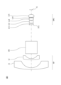
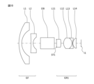
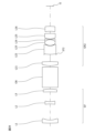
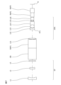
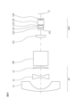
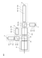
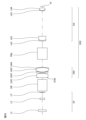
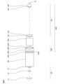
- FIG. 1 is a schematic diagram illustrating an example of the overall configuration of an optical system according to this embodiment.
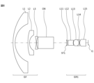
- FIG. 2 is a cross-sectional view of a first optical system included in the optical system of the first embodiment.
- FIG. 3 is a diagram showing various aberrations of the first optical system of the optical system of the first embodiment.
- FIG. 4 is a cross-sectional view of the second optical system included in the optical system of the first embodiment.
- FIG. 5 is a diagram showing various aberrations of the second optical system included in the optical system of the first embodiment.
- FIG. 6 is a cross-sectional view of a first optical system included in the optical system of the second embodiment.
- FIG. 7 is a diagram showing various aberrations of the first optical system of the optical system of the second embodiment.
- FIG. 1 is a schematic diagram illustrating an example of the overall configuration of an optical system according to this embodiment.
- FIG. 2 is a cross-sectional view of a first optical system included in the optical system of the first embodiment.
- FIG. 8 is a cross-sectional view of the second optical system included in the optical system of the second embodiment.
- FIG. 9 is a diagram showing various aberrations of the second optical system of the optical system of the second embodiment.
- FIG. 10 is a cross-sectional view of a first optical system included in the optical system of the third embodiment.
- FIG. 11 is a diagram showing various aberrations of the first optical system of the optical system of the third embodiment.
- FIG. 12 is a cross-sectional view of the second optical system included in the optical system of the third embodiment.
- FIG. 13 is a diagram showing various aberrations of the second optical system of the optical system of the third embodiment.
- FIG. 14 is a cross-sectional view of a first optical system included in the optical system of the fourth embodiment.
- FIG. 15 is a diagram showing various aberrations of the first optical system of the optical system of the fourth embodiment.
- FIG. 16 is a cross-sectional view of the second optical system included in the optical system of the fourth embodiment.
- FIG. 17 is a diagram showing various aberrations of the second optical system of the optical system of the fourth embodiment.
- FIG. 18 is a cross-sectional view of the first optical system included in the optical system of the fifth embodiment.
- FIG. 19 is a diagram showing various aberrations of the first optical system of the optical system of the fifth embodiment.
- FIG. 20 is a cross-sectional view of the second optical system included in the optical system of the fifth embodiment.
- FIG. 21 is a diagram showing various aberrations of the second optical system of the optical system of the fifth embodiment.
- FIG. 22 is a cross-sectional view of the first optical system included in the optical system of the sixth embodiment.
- FIG. 23 is a diagram showing various aberrations of the first optical system of the optical system of the sixth embodiment.
- FIG. 24 is a cross-sectional view of the second optical system included in the optical system of the sixth embodiment.
- FIG. 25 is a diagram showing various aberrations of the second optical system of the optical system of the sixth embodiment.
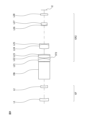
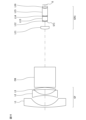
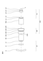
- FIG. 26 is a schematic diagram for explaining the overall configuration of the optical system of the seventh embodiment.
- FIG. 27 is a cross-sectional view of the first optical system included in the optical system of the seventh embodiment.
- FIG. 28 is a diagram showing various aberrations of the first optical system of the optical system of the seventh embodiment.
- FIG. 29 is a cross-sectional view of the second optical system included in the optical system of the seventh embodiment.
- FIG. 30 is a diagram showing various aberrations of the second optical system included in the optical system of the seventh embodiment.
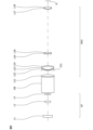
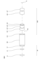
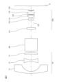
- FIG. 31 is a schematic diagram for explaining the overall configuration of the optical system of the eighth embodiment.
- FIG. 32 is a cross-sectional view of the first optical system included in the optical system of the 8-1 example.
- FIG. 33 is a diagram showing various aberrations of the first optical system of the optical system of Example 8-1.
- FIG. 34 is a cross-sectional view of the second optical system included in the optical system of the 8-1 example.
- FIG. 35 is a diagram showing various aberrations of the second optical system of the optical system of Example 8-1.
- FIG. 36 is a cross-sectional view of the first optical system included in the optical system of the 8-2 embodiment.
- FIG. 37 is a diagram showing various aberrations of the first optical system of the optical system of Example 8-2.
- FIG. 38 is a cross-sectional view of the second optical system included in the optical system of the 8-2 embodiment.
- FIG. 39 is a diagram showing various aberrations of the second optical system of the optical system of the 8-2 example.
- FIG. 40 is a cross-sectional view of the second optical system included in the optical system of the 9-1 example.
- FIG. 41 is a diagram showing various aberrations of the second optical system of the optical system of the 9-1 example.
- FIG. 42 is a cross-sectional view of the second optical system included in the optical system of the 9-2 embodiment.
- optical system optical system
- optical device optical device
- method for manufacturing the optical system according to the embodiments of the present application.
- FIG. 1 is a schematic diagram illustrating an example of the overall configuration of the optical system of this embodiment.
- the optical system 1 of this embodiment has a first optical system OS1 including, from the object side, a front lens group GF, an optical path branching member OB having a branching surface BP1, and a first rear lens group GR1 into which light incident on the front lens group GF and the optical path branching member OB and reflected by the branching surface BP1 is incident.
- the optical system 1 of this embodiment also has a second optical system OS2 including, from the object side, a front lens group GF, an optical path branching member OB, and a second rear lens group GR2 into which light incident on the front lens group GF and the optical path branching member OB and reflected by the branching surface BP1 is incident.
- the front lens group GF has negative refractive power.
- the first optical axis AX1 of the first optical system OS1 and the second optical axis AX2 of the second optical system OS2 are drawn so as not to overlap with each other on the object side of the split surface BP for the sake of explanation.
- the light emitted from the front lens group GF is incident on the light path branching member OB.
- the light path branching member OB is a cube-type beam splitter (prism) having a branching surface BP1 that transmits a portion of the incident light and reflects at least a portion different from the portion of the incident light.
- the light path branching member OB may also be a flat beam splitter (half mirror) having a branching surface BP1.
- first optical system OS1 of the optical system 1 of this embodiment light emitted from the front lens group GF and incident on the optical path branching member OB is reflected by the branching surface BP1, enters the first rear lens group GR1, and is imaged on the first image plane I1.
- second optical system OS2 of the optical system 1 of this embodiment light emitted from the front lens group GF and incident on the optical path branching member OB is transmitted by the branching surface BP1, enters the second rear lens group GR2, and is imaged on the second image plane I2.
- the second optical system OS2 has an overall focal length different from the overall focal length of the first optical system OS1.
- the front lens group GF has a negative refractive power, which makes it possible to adequately widen the angle of view of the wide-angle optical system, which is the one of the first optical system OS1 and the second optical system OS2 that has the shorter total system focal length, and to adequately increase the magnification of the telephoto optical system, which is the one of the first optical system OS1 and the second optical system OS2 that has the longer total system focal length, while allowing the incident light to be appropriately imaged by each optical system.
- the optical system 1 of this embodiment satisfies the following conditional expression. (1) 1.20 ⁇ fB/fA ⁇ 13.00 however, fB: the longer of the total focal length of the first optical system OS1 and the total focal length of the second optical system OS2. fA: the shorter of the total focal length of the first optical system OS1 and the total focal length of the second optical system OS2.
- Conditional formula (1) defines the ratio between the total focal length of the telephoto-side optical system and the total focal length of the wide-angle-side optical system.
- conditional expression (1) in the optical system 1 of this embodiment exceeds the upper limit, it is not possible to sufficiently widen the angle of view of the wide-angle optical system and to sufficiently increase the magnification ratio of the telephoto optical system.
- the effect of this embodiment can be made more certain by setting the upper limit value of conditional formula (1) to 13.00. In order to make the effect of this embodiment more certain, it is preferable to set the upper limit value of conditional formula (1) to 12.55, 12.05, 11.62, 11.16, 10.70, or even 10.00.
- conditional formula (1) falls below the lower limit, it becomes difficult to appropriately correct various aberrations, such as axial chromatic aberration, lateral chromatic aberration, and distortion.
- the effect of this embodiment can be made more certain by setting the lower limit of conditional formula (1) to 1.20. In order to make the effect of this embodiment more certain, it is preferable to set the lower limit of conditional formula (1) to 1.35, 1.50, 1.65, 1.80, 1.95, or even 2.00.
- the optical system 1 of this embodiment satisfies the following conditional expression. (2) 0.20 ⁇ -fF/fA ⁇ 10.00 however, fF: focal length of the front lens group GF; fA: the focal length of the entire system of the first optical system OS1 or the focal length of the entire system of the second optical system OS2, whichever is shorter.
- Conditional formula (2) defines the ratio between the focal length of the front lens group GF and the focal length of the entire wide-angle optical system. By satisfying conditional formula (2), the optical system 1 of this embodiment can appropriately correct various aberrations.
- conditional expression (2) if the value of conditional expression (2) exceeds the upper limit, it becomes difficult to appropriately correct aberrations such as field curvature, astigmatism, and distortion.
- the effect of this embodiment can be made more certain by setting the upper limit value of conditional expression (2) to 10.00. In order to make the effect of this embodiment more certain, it is preferable to set the upper limit value of conditional expression (2) to 9.60, 9.20, 8.805, 8.40, 8.00, or even 7.00.
- conditional expression (2) falls below the lower limit, it becomes difficult to appropriately correct various aberrations such as field curvature, astigmatism, and distortion.
- the effect of this embodiment can be made more certain by setting the lower limit value of conditional expression (2) to 0.20. In order to make the effect of this embodiment more certain, it is preferable to set the lower limit value of conditional expression (2) to 0.26, 0.32, 0.38, 0.44, 0.50, or even 1.00.
- the optical system 1 of this embodiment satisfies the following conditional expression. (3) 0.05 ⁇ -fF/fB ⁇ 3.50 however, fF: focal length of the front lens group GF; fB: the total focal length of the first optical system OS1 or the total focal length of the second optical system OS2, whichever is longer.
- Conditional formula (3) defines the ratio between the focal length of the front lens group GF and the focal length of the telephoto optical system.
- conditional expression (3) if the value of conditional expression (3) exceeds the upper limit, it becomes difficult to appropriately correct various aberrations such as field curvature and astigmatism.
- the effect of this embodiment can be made more certain by setting the upper limit value of conditional expression (3) to 3.50. In order to make the effect of this embodiment more certain, it is preferable to set the upper limit value of conditional expression (3) to 3.30, 3.10, 2.90, 2.70, 2.50, or even 2.00.
- conditional expression (3) falls below the lower limit, the negative power of the front lens group GF becomes too strong, and the overall focal length of the telephoto optical system becomes long, increasing the overall optical length of the telephoto optical system.
- various aberrations such as field curvature, astigmatism, axial chromatic aberration, and chromatic aberration of magnification.
- the effect of this embodiment can be made more certain by setting the lower limit value of conditional expression (3) to 0.05. In order to make the effect of this embodiment more certain, it is preferable to set the lower limit value of conditional expression (3) to 0.06, 0.07, 0.08, 0.09, 0.10, or even 0.20.
- the optical system 1 of this embodiment satisfies the following conditional expression. (4) 3.50 ⁇ -f1/fA ⁇ 50.30 however, f1: focal length of the lens arranged closest to the object in the front lens group GF; fA: the total focal length of the first optical system OS1 or the total focal length of the second optical system OS2, whichever is shorter.
- Conditional expression (4) defines the ratio between the focal length of the lens in the front lens group GF that is located closest to the object and the focal length of the wide-angle optical system.
- conditional expression (4) if the value of conditional expression (4) exceeds the upper limit, the lens in the front lens group GF that is positioned closest to the object becomes large, making it difficult to appropriately correct various aberrations such as field curvature, astigmatism, and distortion.
- the effect of this embodiment can be made more certain by setting the upper limit value of conditional expression (4) to 50.30. In order to make the effect of this embodiment more certain, it is preferable to set the upper limit value of conditional expression (4) to 49.00, 46.00, 43.00, 40.00, or even 36.00.
- conditional expression (4) falls below the lower limit, it becomes difficult to appropriately correct various aberrations such as field curvature, astigmatism, and distortion.
- the effect of this embodiment can be made more certain by setting the lower limit of conditional expression (4) to 3.50. In order to make the effect of this embodiment more certain, it is preferable to set the lower limit of conditional expression (4) to 3.74, 3.98, 4.22, 4.46, 4.70, or even 6.50.
- the optical system 1 of this embodiment satisfies the following conditional expression. (5) 0.25 ⁇ -f1/fB ⁇ 15.00 however, f1: focal length of the lens in the front lens group GF that is located closest to the object side; fB: the total focal length of the first optical system OS1 or the total focal length of the second optical system OS2, whichever is longer.
- Conditional formula (5) defines the ratio between the focal length of the lens in the front lens group GF that is located closest to the object and the focal length of the telephoto optical system.
- conditional expression (5) if the value of conditional expression (5) exceeds the upper limit, the lens in the front lens group GF that is positioned closest to the object becomes large, making it difficult to appropriately correct various aberrations such as field curvature and astigmatism.
- the effect of this embodiment can be made more certain by setting the upper limit value of conditional expression (5) to 15.00. In order to make the effect of this embodiment more certain, it is preferable to set the upper limit value of conditional expression (5) to 14.40, 13.80, 13.20, 12.60, 12.00, or even 11.50.
- conditional expression (5) falls below the lower limit, the negative power of the front lens group GF becomes too strong, and the overall focal length of the telephoto optical system becomes long, increasing the overall optical length of the telephoto optical system.
- various aberrations such as field curvature, astigmatism, axial chromatic aberration, and chromatic aberration of magnification.
- the effect of this embodiment can be made more certain by setting the lower limit of conditional expression (5) to 0.25. In order to make the effect of this embodiment more certain, it is preferable to set the lower limit of conditional expression (5) to 0.30, 0.35, 0.40, 0.45, 0.50, or even 1.00.
- the optical system 1 of this embodiment satisfies the following conditional expression. (6) 0.04 ⁇ -D12/f1 ⁇ 1.50 however, D12: The distance on the optical axis between the image-side lens surface of the lens located closest to the object in the front lens group GF and the object-side lens surface of the lens located adjacent to the image-side lens located closest to the object in the front lens group GF. f1: The focal length of the lens located closest to the object in the front lens group GF.
- Conditional formula (6) specifies the ratio of the distance on the optical axis between the lens located closest to the object in the front lens group GF and the lens located adjacent to that lens on the image plane side, to the focal length of the lens located closest to the object in the front lens group GF.
- conditional expression (6) in the optical system 1 of this embodiment exceeds the upper limit, the lens in the front lens group GF that is located closest to the object side becomes larger, the overall optical length of the wide-angle and telephoto optical systems increases, and it becomes difficult to appropriately correct various aberrations such as field curvature, coma, and chromatic aberration of magnification.
- the effect of this embodiment can be made more certain by setting the upper limit value of conditional expression (6) to 1.50. In order to make the effect of this embodiment more certain, it is preferable to set the upper limit value of conditional expression (6) to 1.44, 1.38, 1.32, 1.26, 1.20, or even 0.85.
- conditional expression (6) falls below the lower limit, it becomes difficult to appropriately correct various aberrations, such as field curvature, coma, and lateral chromatic aberration.
- the effect of this embodiment can be made more certain by setting the lower limit value of conditional expression (6) to 0.04. In order to make the effect of this embodiment more certain, it is preferable to set the lower limit value of conditional expression (6) to 0.05, 0.06, 0.07, 0.08, 0.09, or even 0.11.
- the optical system 1 of this embodiment satisfies the following conditional expression. (7) 0.30 ⁇ TLB/TLA ⁇ 3.50 however, TLB: total optical length of the optical system having the longer total system focal length out of the first optical system OS1 and the second optical system OS2. TLA: total optical length of the optical system having the shorter total system focal length out of the first optical system OS1 and the second optical system OS2.
- Conditional expression (7) defines the ratio between the total optical length of the telephoto side optical system and the total optical length of the wide-angle side optical system.
- conditional expression (7) if the value of conditional expression (7) exceeds the upper limit, the total optical length of the telephoto optical system increases. In addition, it becomes difficult to appropriately correct various aberrations such as field curvature, astigmatism, and distortion in the wide-angle optical system.
- the effect of this embodiment can be made more certain by setting the upper limit value of conditional expression (7) to 3.50. In order to make the effect of this embodiment more certain, it is preferable to set the upper limit value of conditional expression (7) to 3.30, 3.10, 2.90, 2.70, 2.50, or even 2.25.
- conditional expression (7) falls below the lower limit, the total optical length of the wide-angle optical system increases. In addition, it becomes difficult to appropriately correct various aberrations such as field curvature, astigmatism, and coma in the wide-angle optical system.
- the effect of this embodiment can be made more certain by setting the lower limit of conditional expression (7) to 0.30. In order to make the effect of this embodiment more certain, it is preferable to set the lower limit of conditional expression (7) to 0.38, 0.46, 0.54, 0.62, 0.70, or even 0.85.
- the optical system 1 of this embodiment satisfies the following conditional expression. (8) 0.30 ⁇ -(r12+r11)/(r12-r11) ⁇ 4.70 however, r12: radius of curvature of the image-side lens surface of the lens arranged closest to the object in the front lens group GF. r11: radius of curvature of the object-side lens surface of the lens arranged closest to the object in the front lens group GF.
- Conditional formula (8) defines the shape factor of the lens in the front lens group GF that is located closest to the object.
- the optical system 1 of this embodiment can appropriately correct various aberrations such as field curvature, astigmatism, distortion, and coma.
- conditional expression (8) if the value of conditional expression (8) exceeds the upper limit, it becomes difficult to appropriately correct aberrations such as field curvature, astigmatism, and distortion.
- the effect of this embodiment can be made more certain by setting the upper limit value of conditional expression (8) to 4.70. In order to make the effect of this embodiment more certain, it is preferable to set the upper limit value of conditional expression (8) to 4.60, 4.50, 4.40, 4.30, 4.20, or even 3.50.
- conditional expression (8) falls below the lower limit, it becomes difficult to appropriately correct various aberrations such as field curvature, astigmatism, and coma.
- the effect of this embodiment can be made more certain by setting the lower limit value of conditional expression (8) to 0.30. In order to make the effect of this embodiment more certain, it is preferable to set the lower limit value of conditional expression (8) to 0.34, 0.38, 0.42, 0.46, 0.50, or even 0.90.
- the optical system 1 of this embodiment satisfies the following conditional expression. (9) 0.10 ⁇ (r21+r12)/(r21-r12) ⁇ 3.30 however, r21: radius of curvature of the object-side lens surface of the lens arranged adjacent to the image surface side of the lens arranged closest to the object in the front lens group GF. r12: radius of curvature of the image surface side of the lens arranged closest to the object in the front lens group GF.
- Conditional formula (9) defines the shape factor of the air lens configured between the lens located closest to the object in the front lens group GF and the lens located adjacent to the image surface side of the lens located closest to the object in the front lens group GF.
- conditional expression (9) if the value of conditional expression (9) exceeds the upper limit, it becomes difficult to appropriately correct various aberrations such as field curvature and astigmatism.
- the upper limit value of conditional expression (9) is set to 3.30, thereby making it possible to ensure the effect of this embodiment. In order to ensure the effect of this embodiment, it is preferable to set the upper limit value of conditional expression (9) to 3.00, 2.90, 2.60, 2.30, or even 2.00.
- conditional expression (9) falls below the lower limit, it becomes difficult to appropriately correct various aberrations such as field curvature and astigmatism.
- the effect of this embodiment can be made more certain by setting the lower limit of conditional expression (9) to 0.10. In order to make the effect of this embodiment more certain, it is preferable to set the lower limit of conditional expression (9) to 0.14, 0.18, 0.22, 0.26, or even 0.29.
- the optical system 1 of this embodiment satisfies the following conditional expression. (10) 0.30 ⁇ D12/fA ⁇ 11.30 however, D12: the distance on the optical axis between the image-side lens surface of the lens arranged closest to the object in the front lens group GF and the object-side lens surface of the lens arranged adjacent to the image-side surface of the lens arranged closest to the object in the front lens group GF. fA: the total focal length of the first optical system OS1 or the total focal length of the second optical system OS1, whichever is shorter.
- Conditional formula (10) defines the ratio of the distance on the optical axis between the lens in the front lens group GF that is located closest to the object and the lens that is located adjacent to that lens on the image plane side, to the overall focal length of the wide-angle optical system.
- conditional expression (10) if the value of conditional expression (10) exceeds the upper limit, the total optical length of the wide-angle optical system increases. In addition, it becomes difficult to appropriately correct various aberrations such as field curvature and coma.
- the effect of this embodiment can be made more certain by setting the upper limit value of conditional expression (10) to 11.30. In order to make the effect of this embodiment more certain, it is preferable to set the upper limit value of conditional expression (10) to 10.80, 10.30, 9.80, 9.30, 8.85, or even 8.40.
- conditional expression (10) falls below the lower limit, it becomes difficult to appropriately correct various aberrations, including coma.
- the effect of this embodiment can be made more certain by setting the lower limit of conditional expression (10) to 0.30. In order to make the effect of this embodiment more certain, it is preferable to set the lower limit of conditional expression (10) to 0.35, 0.40, 0.45, 0.50, 0.55, or even 1.00.
- the optical system 1 of this embodiment satisfies the following conditional expression. (11) 0.07 ⁇ D12/fB ⁇ 4.30 however, D12: the distance on the optical axis between the image-side lens surface of the lens arranged closest to the object in the front lens group GF and the object-side lens surface of the lens arranged adjacent to the image-side surface of the lens arranged closest to the object in the front lens group GF. fB: the total focal length of the first optical system OS1 or the total focal length of the second optical system OS2, whichever is longer.
- Conditional formula (11) defines the ratio of the distance on the optical axis between the lens in the front lens group GF that is located closest to the object and the lens that is located adjacent to that lens on the image plane side, to the total focal length of the telephoto optical system.
- conditional expression (11) if the value of conditional expression (11) exceeds the upper limit, the total optical length of the telephoto optical system increases. In addition, it becomes difficult to appropriately correct various aberrations such as field curvature and coma.
- the effect of this embodiment can be made more certain by setting the upper limit value of conditional expression (11) to 4.30. In order to make the effect of this embodiment more certain, it is preferable to set the upper limit value of conditional expression (11) to 4.05, 3.80, 3.55, 3.30, 3.00, or even 2.70.
- conditional expression (11) falls below the lower limit, it becomes difficult to appropriately correct various aberrations, such as coma, axial chromatic aberration, and chromatic aberration of magnification.
- the effect of this embodiment can be made more certain by setting the lower limit of conditional expression (11) to 0.07. In order to make the effect of this embodiment more certain, it is preferable to set the lower limit of conditional expression (11) to 0.08, 0.09, 0.11, 0.12, 0.13, or even 0.35.
- the optical system 1 of this embodiment satisfies the following conditional expression. (12) 1.20 ⁇ ⁇ A/ ⁇ B ⁇ 15.00 however, ⁇ A: half angle of view of the optical system having a shorter total system focal length out of the first optical system OS1 and the second optical system OS2. ⁇ B: half angle of view of the optical system having a longer total system focal length out of the first optical system OS1 and the second optical system OS2.
- Conditional formula (12) defines the ratio between the half angle of view of the wide-angle optical system and the half angle of view of the telephoto optical system.
- conditional expression (12) if the value of conditional expression (12) exceeds the upper limit, it becomes difficult to properly correct various aberrations such as field curvature, astigmatism, and distortion in the wide-angle optical system, and it becomes difficult to properly correct various aberrations such as field curvature, astigmatism, axial chromatic aberration, and chromatic aberration of magnification in the telephoto optical system.
- the effect of this embodiment can be made more certain by setting the upper limit value of conditional expression (12) to 15.00. In order to make the effect of this embodiment more certain, it is preferable to set the upper limit value of conditional expression (12) to 14.60, 14.20, 13.80, 13.40, 13.00, or even 11.40.
- conditional expression (12) falls below the lower limit, it is not possible to sufficiently increase the magnification ratio of the telephoto optical system while simultaneously making the angle of view of the wide-angle optical system sufficiently wide.
- the effect of this embodiment can be made more certain by setting the lower limit of conditional expression (12) to 1.20. In order to make the effect of this embodiment more certain, it is preferable to set the lower limit of conditional expression (12) to 1.31, 1.42, 1.53, 1.64, 1.75, or even 2.00.
- the optical system 1 of this embodiment satisfies the following conditional expression. (13) 0.20 ⁇ fpA/fpB ⁇ 2.50 however, fpA: a composite focal length of a positive lens component arranged continuously from the positive lens component arranged closest to the object to the image surface side in a rear lens group included in the optical system of the first optical system OS1 or the second optical system OS2, whichever has a shorter total system focal length, of the first rear lens group GR1 and the second rear lens group GR2.
- fpB a composite focal length of a positive lens component arranged continuously from the positive lens component arranged closest to the object to the image surface side in a rear lens group included in the optical system of the first optical system OS1 or the second optical system OS2, whichever has a longer total system focal length, of the first rear lens group GR1 and the second rear lens group GR2.
- Conditional expression (13) specifies the ratio between the composite focal length of the positive lens components arranged in succession from the positive lens component arranged closest to the object in the rear lens group included in the wide-angle optical system to the positive lens components arranged in succession from the positive lens component arranged closest to the object in the rear lens group included in the telephoto optical system to the positive lens components arranged in succession from the positive lens component arranged closest to the object in the rear lens group included in the telephoto optical system.
- conditional expression (13) if the value of conditional expression (13) exceeds the upper limit, it becomes difficult to appropriately correct various aberrations such as spherical aberration and coma.
- the effect of this embodiment can be made more certain by setting the upper limit value of conditional expression (13) to 2.50. In order to make the effect of this embodiment more certain, it is preferable to set the upper limit value of conditional expression (13) to 2.40, 2.30, 2.20, 2.10, or even 2.00.
- conditional expression (13) falls below the lower limit, it becomes difficult to appropriately correct various aberrations such as spherical aberration and coma.
- the effect of this embodiment can be made more certain by setting the lower limit of conditional expression (13) to 0.20. In order to make the effect of this embodiment more certain, it is preferable to set the lower limit of conditional expression (13) to 0.24, 0.28, 0.32, 0.36, or even 0.40.
- the optical system 1 of this embodiment satisfies the following conditional expression. (14) 0.33 ⁇
- Conditional formula (14) defines the ratio between the focal length of the rear lens group included in the telephoto optical system and the focal length of the rear lens group included in the wide-angle optical system.
- conditional expression (14) if the value of conditional expression (14) exceeds the upper limit, it becomes difficult to appropriately correct various aberrations such as spherical aberration and coma.
- the effect of this embodiment can be made more certain by setting the upper limit value of conditional expression (14) to 65.00. In order to make the effect of this embodiment more certain, it is preferable to set the upper limit value of conditional expression (14) to 63.70, 62.40, 61.10, 59.80, 58.50, or even 50.50.
- conditional expression (14) falls below the lower limit, it becomes difficult to appropriately correct various aberrations such as spherical aberration and coma.
- the effect of this embodiment can be made more certain by setting the lower limit of conditional expression (14) to 0.33. In order to make the effect of this embodiment more certain, it is preferable to set the lower limit of conditional expression (14) to 0.39, 0.45, 0.51, 0.57, 0.63, or even 0.75.
- the optical system 1 of this embodiment satisfies the following conditional expression. (15) 7.00 ⁇ TLB/fA ⁇ 110.00 however, TLB: total optical length of the optical system having the longer total system focal length of the first optical system OS1 or the second optical system OS2. fA: the shorter total system focal length of the first optical system OS1 or the second optical system OS2.
- Conditional formula (15) defines the ratio between the total optical length of the telephoto optical system and the total focal length of the wide-angle optical system.
- conditional expression (15) exceeds the upper limit, the total optical length of the telephoto optical system increases. In addition, it becomes difficult to appropriately correct various aberrations such as field curvature, astigmatism, and coma.
- the effect of this embodiment can be made more certain by setting the upper limit value of conditional expression (15) to 110.00. In order to make the effect of this embodiment more certain, it is preferable to set the upper limit value of conditional expression (15) to 107.50, 105.00, 102.50, 100.00, or even 97.50.
- conditional expression (15) falls below the lower limit, it becomes difficult to appropriately correct various aberrations, such as distortion, curvature of field, and astigmatism, particularly in the wide-angle optical system.
- the effect of this embodiment can be made more certain by setting the lower limit of conditional expression (15) to 7.00. In order to make the effect of this embodiment more certain, it is preferable to set the lower limit of conditional expression (15) to 8.16, 9.32, 10.48, 11.64, 12.80, or even 20.00.
- the optical system 1 of this embodiment satisfies the following conditional expression. (16) 0.30 ⁇ TLA/fB ⁇ 20.50 however, TLA: the total optical length of the optical system having the shorter total system focal length of either the first optical system OS1 or the second optical system OS2. fB: the longer total system focal length of either the first optical system OS1 or the second optical system OS2.
- Conditional formula (16) defines the ratio between the total optical length of the wide-angle optical system and the total focal length of the telephoto optical system.
- conditional expression (16) if the value of conditional expression (16) exceeds the upper limit, the total optical length of the wide-angle optical system increases. In addition, it becomes difficult to appropriately correct various aberrations such as field curvature, astigmatism, and coma.
- the effect of this embodiment can be made more certain by setting the upper limit value of conditional expression (16) to 20.50. In order to make the effect of this embodiment more certain, it is preferable to set the upper limit value of conditional expression (16) to 19.80, 19.10, 18.40, 17.80, or even 16.50.
- conditional expression (16) falls below the lower limit, it becomes difficult to appropriately correct various aberrations, such as field curvature, astigmatism, axial chromatic aberration, and chromatic aberration of magnification, particularly in the telephoto optical system.
- the effect of this embodiment can be made more certain by setting the lower limit of conditional expression (16) to 0.30. In order to make the effect of this embodiment more certain, it is preferable to set the lower limit of conditional expression (16) to 0.35, 0.40, 0.45, 0.50, 0.55, or even 2.05.
- the optical system 1 of this embodiment satisfies the following conditional expression. (17) 1.70 ⁇ nd1 ⁇ 2.01 however, nd1: refractive index for the d-line of the lens arranged closest to the object in the front lens group GF
- Conditional formula (17) specifies the refractive index for the d-line of the lens in the front lens group GF that is located closest to the object.
- conditional expression (17) in the optical system 1 of this embodiment exceeds the upper limit, the degree of freedom in selecting the glass material used in the lens decreases, making color correction difficult.
- the effect of this embodiment can be made more certain by setting the upper limit value of conditional expression (17) to 2.01. In order to make the effect of this embodiment more certain, it is preferable to set the upper limit value of conditional expression (17) to 1.97, 1.93, 1.88, 1.84, or even 1.80.
- conditional formula (17) falls below the lower limit, the power of the lens located closest to the object in the front lens group GF becomes weak, making it difficult to correct the curvature of field, particularly in the wide-angle optical system.
- the effect of this embodiment can be made more certain by setting the lower limit of conditional expression (17) to 1.70. In order to make the effect of this embodiment more certain, it is preferable to set the lower limit of conditional expression (17) to 1.71.
- the optical system 1 of this embodiment satisfies the following conditional expression. (18) 1.50 ⁇ nd2 ⁇ 2.01 however, nd2: refractive index for the d-line of the lens arranged adjacent to the image plane side of the lens arranged closest to the object side in the front lens group GF
- Conditional formula (18) specifies the refractive index for the d-line of the lens arranged adjacent to the image plane side of the lens arranged closest to the object in the front lens group GF.
- conditional expression (18) in the optical system 1 of this embodiment exceeds the upper limit, the degree of freedom in selecting the glass material used in the lens decreases, making color correction difficult.
- the effect of this embodiment can be made more certain by setting the upper limit value of conditional expression (18) to 2.01. In order to make the effect of this embodiment more certain, it is preferable to set the upper limit value of conditional expression (18) to 1.95, 1.89, 1.82, 1.76, or even 1.70.
- conditional formula (18) falls below the lower limit, the power of the lens arranged adjacent to the image surface side of the lens arranged closest to the object in the front lens group GF becomes weak, making it difficult to correct the curvature of field, particularly in the wide-angle optical system.
- the effect of this embodiment can be made more certain by setting the lower limit of conditional expression (18) to 1.50. In order to make the effect of this embodiment more certain, it is preferable to set the lower limit of conditional expression (18) to 1.55.
- the optical system 1 of this embodiment satisfies the following conditional expression. (19) 1.55 ⁇ ndaveF ⁇ 2.01 however, ndaveF: average refractive index for the d-line of the lenses in the front lens group GF
- Conditional formula (19) specifies the average refractive index for the d-line of the lenses in the front lens group GF. By satisfying conditional formula (19), the optical system 1 of this embodiment can appropriately correct various aberrations.
- conditional formula (19) if the value of conditional formula (19) exceeds the upper limit, the degree of freedom in selecting the glass material used for the lenses of the front lens GF decreases, making color correction difficult.
- the effect of this embodiment can be made more certain by setting the upper limit value of conditional expression (19) to 2.01. In order to make the effect of this embodiment more certain, it is preferable to set the upper limit value of conditional expression (19) to 1.95, 1.89, 1.83, 1.77, or even 1.71.
- conditional expression (19) falls below the lower limit, it becomes difficult to correct various aberrations.
- the effect of this embodiment can be made more certain by setting the lower limit of conditional expression (19) to 1.55. In order to make the effect of this embodiment more certain, it is preferable to set the lower limit of conditional expression (19) to 1.55, 1.57, 1.59, 1.61, 1.63, or even 1.65.
- the optical system 1 of this embodiment satisfies the following conditional expression. (20) 45° ⁇ ⁇ A ⁇ 120° however, ⁇ A: half angle of view of the optical system having the shorter total focal length out of the first optical system OS1 and the second optical system OS2
- Conditional formula (20) defines the half angle of view of the wide-angle optical system.
- the optical system 1 of this embodiment can satisfactorily correct various aberrations such as field curvature, astigmatism, and distortion while providing a sufficiently wide angle of view of the wide-angle optical system.
- conditional expression (20) if the value of conditional expression (20) exceeds the upper limit, it becomes difficult to appropriately correct various aberrations such as field curvature, astigmatism, and distortion.
- the effect of this embodiment can be made more certain by setting the upper limit value of conditional expression (20) to 120°. In order to make the effect of this embodiment more certain, it is preferable to set the upper limit value of conditional expression (20) to 118°, 115°, 110°, 105°, or even 100°.
- conditional expression (20) falls below the lower limit, the angle of view of the wide-angle optical system cannot be made sufficiently wide.
- the effect of this embodiment can be made more certain by setting the lower limit of conditional expression (20) to 45°. In order to make the effect of this embodiment more certain, it is preferable to set the lower limit of conditional expression (20) to 50°, 55°, 60°, 65°, or even 70°.
- the optical system 1 of this embodiment satisfies the following conditional expression. (21) 3° ⁇ ⁇ B ⁇ 30° however, ⁇ B: half angle of view of the optical system having the longer total focal length out of the first optical system OS1 and the second optical system OS2
- Conditional expression (21) defines the half angle of view of the telephoto optical system.
- conditional expression (21) in the optical system 1 of this embodiment exceeds the upper limit, the magnification ratio of the telephoto optical system cannot be made sufficiently large.
- the upper limit value of conditional expression (21) is set to 30°, thereby making it possible to ensure the effect of this embodiment. In order to ensure the effect of this embodiment, it is preferable to set the upper limit value of conditional expression (21) to 28°, 26°, 24°, 22°, or even 20°.
- conditional expression (21) falls below the lower limit, chromatic aberration cannot be appropriately corrected.
- the effect of this embodiment can be made more certain by setting the lower limit of conditional expression (21) to 3°. In order to make the effect of this embodiment more certain, it is preferable to set the lower limit of conditional expression (21) to 4°, 5°, 6°, 7°, or even 8°.
- the optical system 1 of this embodiment satisfies the following conditional expression. (22) 0.10 ⁇ Wi/(1-Wi) ⁇ 1.00 however, Wi: When the optical path of the first optical system OS1 or the second optical system OS2, whichever has the shorter total system focal length, is reflected by the branching surface BP, the reflectance of the branching surface BP; when the optical path of the first optical system OS1 or the second optical system OS2, whichever has the shorter total system focal length, is transmitted by the branching surface BP, the transmittance of the branching surface BP.
- Conditional formula (22) specifies the ratio between the reflectance or transmittance when the optical path of the wide-angle side optical system is reflected or transmitted by the splitting surface BP and the proportion of the optical path of the wide-angle side optical system that is not reflected or transmitted when it is reflected or transmitted by the splitting surface BP.
- conditional formula (22) the optical system 1 of this embodiment can keep the difference in brightness between the image formed on the image plane by the wide-angle side optical system with a smaller F-number and the image formed on the image plane by the telephoto side optical system with a larger F-number within an appropriate range.
- conditional expression (22) if the value of conditional expression (22) exceeds the upper limit, the image formed on the image plane by the telephoto optical system becomes too dark.
- the effect of this embodiment can be made more certain by setting the upper limit value of conditional expression (22) to 1.00. In order to make the effect of this embodiment more certain, it is preferable to set the upper limit value of conditional expression (22) to 0.94, 0.88, 0.82, 0.76, or even 0.70.
- conditional expression (22) falls below the lower limit, the image formed on the image plane by the wide-angle optical system becomes too dark.
- the effect of this embodiment can be made more certain by setting the lower limit value of conditional expression (22) to 0.10. In order to make the effect of this embodiment more certain, it is preferable to set the lower limit value of conditional expression (22) to 0.11.
- the optical path branching member OB is preferably a prism.
- the optical system 1 of this embodiment which has such a configuration, can appropriately correct the field curvature and can also increase the precision of the branching surface BP1 of the optical path branching member OB.
- the lens in the front lens group GF that is positioned closest to the object has negative refractive power.
- the optical system 1 of this embodiment which has such a configuration, can provide a sufficiently wide angle of view for the wide-angle optical system.
- the front lens group GF is made up of three or more lens components.
- a lens component refers to a single lens or a cemented lens.
- the optical system 1 of this embodiment can be configured to be compact.
- At least one of the first rear lens group GR1 and the second rear lens group GR2 has a second optical path branching member having a second branching surface that reflects a portion of the incident light and transmits at least a portion different from the portion of the incident light, a third rear lens group into which at least a portion of the light reflected at the second branching surface is incident, and a fourth rear lens group into which at least a portion of the light transmitted by the second branching surface is incident.
- the optical system 1 of this embodiment having such a configuration can form multiple images using the first optical system OS1 or the second optical system OS2.
- the lens group having the second optical path branching member, the third rear lens group, and the fourth rear lens group among the first rear lens group GR1 and the second rear lens group GR2 has an intermediate lens group having a positive refractive power between the optical path branching member OB and the second optical path branching member.
- the optical system 1 of this embodiment having such a configuration can be made compact by reducing the number of lens components constituting the rear lens group having the intermediate lens group among the first rear lens group GR1 and the second rear lens group GR2.
- the image plane of the first optical system OS1 and the image plane of the second optical system OS2 are arranged on the same plane.
- the optical system 1 of this embodiment having such a configuration can receive the image obtained by the first optical system OS1 and the image obtained by the second optical system OS2 using a single light receiving section arranged on the image plane, making it possible to miniaturize an optical device including the optical system. Furthermore, in an optical device including an optical system having such a configuration, it is easy to synchronize the timing of capturing the two images.
- the overall focal length of the first optical system OS1 is longer than the overall focal length of the second optical system OS2.
- the optical system 1 of this embodiment which has such a configuration, can shorten the distance from the lens surface closest to the object to the image plane.
- the first optical system OS1 further has, between the optical path branching member OB and the image plane, a first optical path changing member that changes the optical path of the light reflected at the branching surface BP1 so that it is parallel to the optical path of the light transmitted by the branching surface BP1, and a second optical path changing member that changes the optical path of the light reflected at the branching surface BP1 changed by the first optical path changing member so that the distance between the optical path of the light transmitted by the branching surface BP1 is shortened.
- the optical system 1 of this embodiment which has such a configuration, can form two images close to each other, making it possible to configure an optical device that receives each image using a single light receiving section.
- the above configuration makes it possible to realize an optical system that splits the incoming light and appropriately focuses each of the light into an image.
- the optical device of this embodiment has an optical system with the above-mentioned configuration. This makes it possible to split the incident light and obtain image data corresponding to each light.
- the optical device of this embodiment preferably has a drive unit that changes the orientation of the optical system based on image information representing the image of the optical system having the shorter total system focal length out of the first optical system OS1 and the second optical system OS2.
- the optical device of this embodiment has such a configuration that it can appropriately change the orientation of the optical system based on the wide range of conditions represented in the image obtained by the wide-angle optical system.
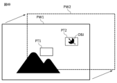
- the drive unit changes the orientation of the optical system so that an object detected from image information is within the angle of view of the optical system having the longer total system focal length out of the first optical system OS1 and the second optical system OS2.
- the optical device of this embodiment has such a configuration that it is possible to change the orientation of the optical system so that the image obtained by the telephoto optical system represents an object contained within a wide range represented by the image obtained by the wide-angle optical system.
- the optical device of this embodiment preferably has a synthesis unit that synthesizes first image information that is an enlarged portion of the image of the optical system having the shorter total system focal length out of the first optical system OS1 and the second optical system OS2, and second image information that represents at least a portion of the image of the optical system having the longer total system focal length out of the first optical system OS1 and the second optical system OS2.
- the optical device of this embodiment which has such a configuration, makes it possible to compare the portion contained in the image obtained by the wide-angle optical system with the portion contained in the image obtained by the telephoto optical system.
- the manufacturing method of the optical system of this embodiment is a manufacturing method of an optical system that has a branching surface BP1 that transmits a part of the incident light and reflects at least a part different from the part of the incident light, and forms an image of a first light that is at least a part of the light reflected by the branching surface BP1 and a second light that is at least a part of the light transmitted by the branching surface BP1, and arranges a first optical system OS1 to have, in order from the object side, a front lens group GF having a negative refractive power, an optical path branching member OB having the branching surface BP1, and a first rear lens group GR1 into which the first light is incident, and arranges a second optical system OS2 to have, in order from the object side, a front lens group GF, an optical path branching member OB, and a second rear lens group GR2 into which the second light is incident, and configures the second optical system OS2 to have a total system focal length different from the
- This method of manufacturing an optical system makes it possible to produce an optical system that splits the incoming light and properly focuses each of the split light into an image.
- the second optical system OS2 has an overall focal length longer than that of the first optical system OS1. That is, the first optical system OS1 corresponds to the wide-angle side optical system, and the second optical system OS2 corresponds to the telephoto side optical system.
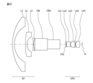
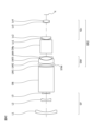
- FIG. 2 is a cross-sectional view of the first optical system OS1 of the optical system 1 of the first embodiment.
- the first optical system OS1 of this embodiment has, in order from the object side, a meniscus negative lens L1 with a convex surface facing the object side, a meniscus negative lens L2 with a convex surface facing the object side, an optical path branching member OB, an aperture stop ST1, a biconvex positive lens L11, a meniscus negative lens L12 with a convex surface facing the object side, a cemented negative lens consisting of a biconvex positive lens L13 and a biconcave negative lens L14, and a biconvex positive lens L15.
- a first image sensor (not shown) composed of a CCD or CMOS or the like is disposed on the image plane I1.
- the negative lens L1 and the negative lens L2 are included in the front lens group GF.
- the positive lens L11, the negative lens L12, the cemented negative lens of the positive lens L13 and the negative lens L14, and the positive lens L15 are included in the first rear lens group GR1.
- Table 1-1 lists the specifications of the first optical system OS1 in this embodiment.
- fA is the overall focal length of the first optical system OS1
- TLA is the total optical length of the first optical system OS1
- FnoA is the F-number of the first optical system OS1
- YmaxA is the maximum image height
- ⁇ A is the half angle of view (degrees)
- Wi is the reflectance of the branching surface BP1. Note that these values listed in [Overall Specifications] are values for the d-line (wavelength 587.6 nm).
- m is the order of the optical surface counted from the object side
- r is the radius of curvature
- d is the surface spacing
- n(d) is the refractive index for the d-line
- ⁇ d is the Abbe number for the d-line.
- an optical surface marked with an "*" indicates that it is aspheric.
- the focal length, radius of curvature and other lengths listed in Table 1-1 are in units of "mm". However, this is not limited to this because the optical system can achieve the same optical performance even when proportionally enlarged or reduced.
- FIG. 3 shows various aberration diagrams of the first optical system OS1 in the optical system 1 of the first embodiment.
- the spherical aberration diagram shows the ratio to the maximum aperture
- the astigmatism diagram shows the half angle of view value
- the coma diagram shows the ratio to the maximum image height.
- Each aberration diagram shows values for the d-line and g-line (wavelength 435.8 nm).
- S indicates the sagittal image plane
- T indicates the meridional image plane.
- the first optical system OS1 of this embodiment properly corrects various aberrations and has high optical performance.
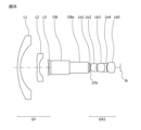
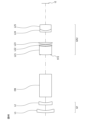
- FIG. 4 is a cross-sectional view of the second optical system OS2 of the optical system 1 of the first embodiment.
- the second optical system OS2 of this embodiment has, in order from the object side, a meniscus negative lens L1 with a convex surface facing the object side, a meniscus negative lens L2 with a convex surface facing the object side, an optical path branching member OB, a biconvex positive lens L21, an aperture stop ST2, a cemented positive lens of a biconvex positive lens L22 and a meniscus negative lens L23 with a concave surface facing the object side, a cemented negative lens of a biconvex positive lens L24 and a biconcave negative lens L25, a cemented negative lens of a meniscus negative lens L26 with a convex surface facing the object side and a biconvex positive lens L27, and a meniscus positive lens L28 with a concave surface facing the object side.
- An imaging element such as a CCD or CMOS is placed on image plane I2.
- the negative lens L1 and the negative lens L2 are included in the front lens group GF.
- the front lens group GF is common to the first optical system OS1, and this is also the case in each embodiment described below.
- the front lens group GF is shown with a smaller aperture than the front lens group GF in FIG. 2, and this is also true in the cross-sectional views of the second optical system OS2 in each embodiment described below.
- the positive lens L21, the aperture stop ST2, the cemented positive lens of the positive lens L22 and the negative lens L23, the cemented negative lens of the positive lens L24 and the negative lens L25, the cemented negative lens of the negative lens L26 and the positive lens L27, and the positive lens L28 are included in the second rear lens group GR2.
- Table 1-2 below lists the specifications of the second optical system OS2 in this embodiment.
- fB is the overall focal length of the second optical system OS2
- TLB is the total optical length of the second optical system OS2
- FnoB is the F-number of the second optical system OS2
- YmaxB is the maximum image height
- ⁇ B is the half angle of view (degrees). Note that these values listed in [Overall Specifications] are values for the d-line.
- FIG. 5 shows various aberration diagrams of the second optical system OS2 in the optical system 1 of the first embodiment.
- the second optical system OS2 of this embodiment appropriately corrects various aberrations and has high optical performance.
- the second optical system OS2 has an overall focal length longer than that of the first optical system OS1. That is, the first optical system OS1 corresponds to the wide-angle side optical system, and the second optical system OS2 corresponds to the telephoto side optical system.
- FIG. 6 is a cross-sectional view of the first optical system OS1 of the optical system 1 of the second embodiment.
- the first optical system OS1 of this embodiment has, in order from the object side, a meniscus negative lens L1 with a convex surface facing the object side, a meniscus negative lens L2 with a convex surface facing the object side, a biconcave negative lens L3, an optical path branching member OB, an aperture stop ST1, a biconvex positive lens L11, a meniscus negative lens L12 with a convex surface facing the object side, a cemented positive lens consisting of a biconvex positive lens L13 and a biconcave negative lens L14, and a biconvex positive lens L15.
- a first image sensor (not shown) composed of a CCD or CMOS or the like is disposed on the image plane I1.
- the negative lens L1, negative lens L2, and negative lens L3 are included in the front lens group GF.
- the positive lens L11, the negative lens L12, the cemented positive lens of the positive lens L13 and the negative lens L14, and the positive lens L15 are included in the first rear lens group GR1.
- Table 2-1 lists the specifications of the first optical system OS1 in this embodiment.
- m is the optical surface that corresponds to the aspheric data
- K is the conic constant
- A4 to A10 are the aspheric coefficients.
- the aspheric surface is expressed by the following formula (a), where y is the height in the direction perpendicular to the optical axis, S(y) is the distance along the optical axis from the tangent plane of the apex of each aspheric surface at height y to each aspheric surface (amount of sag), r is the radius of curvature (paraxial radius of curvature) of the reference spherical surface, K is the conic constant, and An is the n-th order aspheric coefficient. In each embodiment, the second order aspheric coefficient A2 is 0. Also, "En” represents " ⁇ 10 -n ".
- FIG. 7 shows various aberration diagrams of the first optical system OS1 in the optical system 1 of the second embodiment.
- the first optical system OS1 of this embodiment properly corrects various aberrations and has high optical performance.
- FIG. 8 is a cross-sectional view of the second optical system OS2 of the optical system 1 of the second embodiment.
- the second optical system OS2 of this embodiment has, in order from the object side, a meniscus negative lens L1 with a convex surface facing the object side, a meniscus negative lens L2 with a convex surface facing the object side, a biconcave negative lens L3, an optical path branching member OB, a biconvex positive lens L21, an aperture stop ST2, a meniscus negative lens L22 with a convex surface facing the object side, a cemented positive lens of a biconvex positive lens L23 and a meniscus negative lens L24 with a concave surface facing the object side, a cemented negative lens of a biconcave negative lens L25 and a biconvex positive lens L26, and a cemented positive lens of a meniscus negative lens L27 with a convex surface facing the object side and a biconvex positive lens L28.
- An imaging element such as a CCD or CMOS is placed on image plane I2.
- the negative lens L1, the negative lens L2, and the negative lens L3 are included in the front lens group GF.
- the positive lens L21, the aperture stop ST2, the negative lens L22, the cemented positive lens of the positive lens L23 and the negative lens L24, the cemented negative lens of the negative lens L25 and the positive lens L26, and the cemented positive lens of the negative lens L27 and the positive lens L28 are included in the second rear lens group GR2.
- Table 2-2 lists the specifications of the second optical system OS2 in this embodiment.
- FIG. 9 shows various aberration diagrams of the second optical system OS2 in the optical system 1 of the second embodiment.
- the second optical system OS2 of this embodiment appropriately corrects various aberrations and has high optical performance.
- the second optical system OS2 has an overall focal length longer than that of the first optical system OS1. That is, the first optical system OS1 corresponds to the wide-angle side optical system, and the second optical system OS2 corresponds to the telephoto side optical system.
- FIG. 10 is a cross-sectional view of the first optical system OS1 of the optical system 1 of the third embodiment.
- the first optical system OS1 of this embodiment has, in order from the object side, a meniscus negative lens L1 with a convex surface facing the object side, a biconcave negative lens L2, an optical path branching member OB, an aperture stop ST1, a meniscus positive lens L11 with a concave surface facing the object side, a cemented positive lens consisting of a biconvex positive lens L12 and a biconcave negative lens L13, and a meniscus positive lens L14 with a convex surface facing the object side.
- a first image sensor (not shown) composed of a CCD or CMOS or the like is disposed on the image plane I1.
- the negative lens L1 and the negative lens L2 are included in the front lens group GF.
- the positive lens L11, the negative lens L12, the cemented positive lens of the positive lens L13 and the negative lens L14, and the positive lens L15 are included in the first rear lens group GR1.
- Table 3-1 below lists the specifications of the first optical system OS1 in this embodiment.
- FIG. 11 shows various aberration diagrams of the first optical system OS1 in the optical system 1 of the third embodiment.
- the first optical system OS1 of this embodiment properly corrects various aberrations and has high optical performance.
- FIG. 12 is a cross-sectional view of the second optical system OS2 of the optical system 1 of the third embodiment.
- the second optical system OS2 of this embodiment has, in order from the object side, a meniscus negative lens L1 with a convex surface facing the object side, a biconcave negative lens L2, an optical path branching member OB, a meniscus positive lens L21 with a concave surface facing the object side, an aperture stop ST2, a meniscus negative lens L22 with a convex surface facing the object side, a cemented positive lens of a biconvex positive lens L23 and a meniscus negative lens L24 with a concave surface facing the object side, a cemented negative lens of a biconcave negative lens L25 and a biconvex positive lens L26, and a cemented positive lens of a meniscus negative lens L27 with a convex surface facing the object side and a biconvex positive lens L28.
- An imaging element such as a CCD or CMOS is placed on image plane I2.
- the negative lens L1 and the negative lens L2 are included in the front lens group GF.
- the positive lens L21, the aperture stop ST2, the negative lens L22, the cemented positive lens of the positive lens L23 and the negative lens L24, the cemented negative lens of the negative lens L25 and the positive lens L26, and the cemented positive lens of the negative lens L27 and the positive lens L28 are included in the second rear lens group GR2.
- Table 3-2 lists the specifications of the second optical system OS2 in this embodiment.
- FIG. 13 shows various aberration diagrams of the second optical system OS2 in the optical system 1 of the third embodiment.
- the second optical system OS2 of this embodiment appropriately corrects various aberrations and has high optical performance.
- the second optical system OS2 has an overall focal length longer than that of the first optical system OS1. That is, the first optical system OS1 corresponds to the wide-angle side optical system, and the second optical system OS2 corresponds to the telephoto side optical system.
- FIG. 14 is a cross-sectional view of the first optical system OS1 of the optical system 1 of the fourth embodiment.
- the first optical system OS1 of this embodiment has, in order from the object side, a meniscus negative lens L1 with a convex surface facing the object side, a biconcave negative lens L2, a meniscus positive lens L3 with a concave surface facing the object side, an optical path branching member OB, a meniscus positive lens L11 with a convex surface facing the object side, an aperture stop ST1, a meniscus negative lens L12 with a convex surface facing the object side, a cemented positive lens consisting of a biconvex positive lens L13 and a biconcave negative lens L14, a meniscus negative lens L15 with a convex surface facing the object side, and a meniscus positive lens L16 with a convex surface facing the object side.
- a first image sensor (not shown) composed of a CCD or CMOS or the like is disposed on the image plane I1.
- the negative lens L1, the negative lens L2, and the negative lens L3 are included in the front lens group GF.
- the positive lens L11, the aperture stop ST1, the negative lens L12, the cemented positive lens of the positive lens L13 and the negative lens L14, the negative lens L15, and the positive lens L16 are included in the first rear lens group GR1.
- Table 4-1 below lists the specifications of the first optical system OS1 in this embodiment.
- FIG. 15 shows various aberration diagrams of the first optical system OS1 in the optical system 1 of the fourth embodiment.
- the first optical system OS1 of this embodiment properly corrects various aberrations and has high optical performance.
- FIG. 16 is a cross-sectional view of the second optical system OS2 of the optical system 1 of the fourth embodiment.
- the second optical system OS2 of this embodiment has, in order from the object side, a meniscus negative lens L1 with a convex surface facing the object side, a biconcave negative lens L2, a meniscus positive lens L3 with a concave surface facing the object side, an optical path branching member OB, a biconvex positive lens L21, an aperture stop ST2, a meniscus negative lens L22 with a convex surface facing the object side, a cemented negative lens consisting of a biconvex positive lens L23 and a biconcave negative lens L24, a biconvex positive lens L25, a meniscus negative lens L26 with a convex surface facing the object side, and a meniscus positive lens L27 with a concave surface facing the object side.
- An imaging element such as a CCD or CMOS is placed on image plane I2.
- the negative lens L1, the negative lens L2, and the negative lens L3 are included in the front lens group GF.
- the positive lens L21, the aperture stop ST2, the negative lens L22, the cemented negative lens of the positive lens L23 and the negative lens L24, the positive lens L25, the negative lens L26, and the positive lens L27 are included in the second rear lens group GR2.
- Table 4-2 below lists the specifications of the second optical system OS2 in this embodiment.
- FIG. 17 shows various aberration diagrams of the second optical system OS2 in the optical system 1 of the fourth embodiment.
- the second optical system OS2 of this embodiment appropriately corrects various aberrations and has high optical performance.
- the second optical system OS2 has an overall focal length longer than the overall focal length of the first optical system OS1. That is, the first optical system OS1 corresponds to the wide-angle side optical system, and the second optical system OS2 corresponds to the telephoto side optical system.
- FIG. 18 is a cross-sectional view of the first optical system OS1 of the optical system 1 of the fifth embodiment.
- the first optical system OS1 of this embodiment has, in order from the object side, a meniscus negative lens L1 with a convex surface facing the object side, a biconcave negative lens L2, a meniscus positive lens L3 with a convex surface facing the object side, an optical path branching member OB, a biconvex positive lens L11, an aperture stop ST1, a cemented negative lens consisting of a biconvex positive lens L12 and a biconcave negative lens L13, a biconvex positive lens L14, and a meniscus positive lens L15 with a convex surface facing the object side.
- a first image sensor (not shown) composed of a CCD or CMOS or the like is disposed on the image plane I1.
- the negative lens L1, negative lens L2, and negative lens L3 are included in the front lens group GF.
- the positive lens L11, the aperture stop ST1, the cemented negative lens of the positive lens L12 and the negative lens L13, the positive lens L14, and the positive lens L15 are included in the first rear lens group GR1.
- Table 5-1 below lists the specifications of the first optical system OS1 in this embodiment.
- FIG. 19 shows various aberration diagrams of the first optical system OS1 in the optical system 1 of the fifth embodiment.
- the first optical system OS1 of this embodiment properly corrects various aberrations and has high optical performance.
- FIG. 20 is a cross-sectional view of the second optical system OS2 of the optical system 1 of the fifth embodiment.
- the second optical system OS2 of this embodiment has, in order from the object side, a meniscus negative lens L1 with a convex surface facing the object side, a biconcave negative lens L2, a meniscus positive lens L3 with a convex surface facing the object side, an optical path branching member OB, a biconvex positive lens L21, an aperture stop ST2, a meniscus negative lens L22 with a convex surface facing the object side, a cemented negative lens consisting of a biconvex positive lens L23 and a biconcave negative lens L24, a biconvex positive lens L25, a meniscus negative lens L26 with a convex surface facing the object side, and a biconvex positive lens L27.
- An imaging element such as a CCD or CMOS is placed on image plane I2.
- the negative lens L1, the negative lens L2, and the negative lens L3 are included in the front lens group GF.
- the positive lens L21, the aperture stop ST2, the negative lens L22, the cemented negative lens of the positive lens L23 and the negative lens L24, the positive lens L25, the negative lens L26, and the positive lens L27 are included in the second rear lens group GR2.
- Table 5-2 below lists the specifications of the second optical system OS2 in this embodiment.
- FIG. 21 shows various aberration diagrams of the second optical system OS2 in the optical system 1 of the fifth embodiment.
- the second optical system OS2 of this embodiment appropriately corrects various aberrations and has high optical performance.
- the second optical system OS2 has an overall focal length longer than the overall focal length of the first optical system OS1. That is, the first optical system OS1 corresponds to the wide-angle side optical system, and the second optical system OS2 corresponds to the telephoto side optical system.
- FIG. 22 is a cross-sectional view of the first optical system OS1 of the optical system 1 of the sixth embodiment.
- the first optical system OS1 of this embodiment has, in order from the object side, a meniscus negative lens L1 with a convex surface facing the object side, a biconcave negative lens L2, a meniscus positive lens L3 with a concave surface facing the object side, an optical path branching member OB, a biconvex positive lens L11, an aperture stop ST1, a meniscus negative lens L12 with a convex surface facing the object side, a cemented positive lens consisting of a biconvex positive lens L13 and a biconcave negative lens L14, a biconvex positive lens L15, and a meniscus negative lens L16 with a convex surface facing the object side.
- a first image sensor (not shown) composed of a CCD or CMOS or the like is disposed on the image plane I1.
- the negative lens L1, negative lens L2, and negative lens L3 are included in the front lens group GF.
- the positive lens L11, the aperture stop ST1, the positive lens L12, the cemented positive lens of the positive lens L13 and the negative lens L14, the positive lens L15, and the negative lens L16 are included in the first rear lens group GR1.
- Table 6-1 below lists the specifications of the first optical system OS1 in this embodiment.
- FIG. 23 shows various aberration diagrams of the first optical system OS1 in the optical system 1 of the sixth embodiment.
- the first optical system OS1 of this embodiment properly corrects various aberrations and has high optical performance.
- FIG. 24 is a cross-sectional view of the second optical system OS2 of the optical system 1 of the sixth embodiment.
- the second optical system OS2 of this embodiment has, in order from the object side, a meniscus negative lens L1 with a convex surface facing the object side, a biconcave negative lens L2, a meniscus positive lens L3 with a concave surface facing the object side, an optical path branching member OB, a biconvex positive lens L21, an aperture stop ST2, a meniscus negative lens L22 with a convex surface facing the object side, a cemented positive lens consisting of a biconvex positive lens L23 and a biconcave negative lens L24, a biconvex positive lens L25, and a meniscus negative lens L26 with a concave surface facing the object side.
- An imaging element such as a CCD or CMOS is placed on image plane I2.
- the negative lens L1, the negative lens L2, and the negative lens L3 are included in the front lens group GF.
- the positive lens L21, the aperture stop ST2, the negative lens L22, the cemented positive lens of the positive lens L23 and the negative lens L24, the positive lens L25, and the negative lens L26 are included in the second rear lens group GR2.
- Table 6-2 lists the specifications of the second optical system OS2 in this embodiment.
- FIG. 25 shows various aberration diagrams of the second optical system OS2 in the optical system 1 of the sixth embodiment.
- the second optical system OS2 of this embodiment appropriately corrects various aberrations and has high optical performance.
- FIG. 26 is a schematic diagram for explaining the overall configuration of the optical system 1 of the seventh embodiment.
- the first optical system OS1 has an overall focal length that is longer than the overall focal length of the second optical system OS2.
- the first optical system OS1 corresponds to the telephoto optical system
- the second optical system OS2 corresponds to the wide-angle optical system.
- the image plane I1 of the first optical system OS1 and the image plane I2 of the second optical system OS2 are arranged on the same plane.
- the first optical system OS1 in this embodiment has a first optical path changing member between the optical path branching member OB and the image surface I1, which changes the optical path of the light reflected by the branching surface BP1 so that it is parallel to the optical path of the light transmitted by the branching surface BP1.
- the first optical path changing member is composed of a right-angle prism RAP1 having a reflecting surface that changes the incident light so that it is parallel to the optical path of the light transmitted by the branching surface BP1.
- the first optical path changing member may also be composed of a mirror having a reflecting surface that changes the incident light so that it is parallel to the optical path of the light transmitted by the branching surface BP1.
- the first optical system OS1 in this embodiment has a second optical path changing member between the first optical path changing member and the image plane, which changes the optical path of the light reflected by the branching surface BP1 changed by the first optical path changing member so that the distance between the optical path of the light transmitted by the branching surface BP1 is shortened.
- the second optical path changing member is composed of a right-angle prism RAP2 having a reflecting surface that emits the incident light in a direction approaching the optical path of the light transmitted by the splitting surface BP1, and a right-angle prism RAP3 that changes the incident light to be parallel to the optical path of the light transmitted by the splitting surface BP1 and emits it toward the image surface I1.
- At least one of the right-angle prisms RAP2 and RAP3 may be composed of a mirror.
- FIG. 27 is a cross-sectional view of the first optical system OS1 of the optical system 1 of the seventh embodiment.
- the first optical system OS1 of this embodiment has, in order from the object side, a meniscus negative lens L1 with a convex surface facing the object side, a biconcave negative lens L2, a meniscus positive lens L3 with a concave surface facing the object side, an optical path branching member OB, a right-angle prism RAP1, a biconvex positive lens L11, an aperture stop ST1, a meniscus negative lens L12 with a convex surface facing the object side, a cemented positive lens consisting of a biconvex positive lens L13 and a biconcave negative lens L14, a biconvex positive lens L15, a meniscus negative lens L16 with a concave surface facing the object side, a right-angle prism RAP2, and a right-angle prism RAP3.
- An imaging element such as a CCD or CMOS is placed on the image plane I1.
- the negative lens L1, negative lens L2, and negative lens L3 are included in the front lens group GF.
- the positive lens L11, the aperture stop ST1, the negative lens L12, the cemented positive lens of the positive lens L13 and the negative lens L14, the positive lens L15, and the negative lens L16 are included in the first rear lens group GR1.
- Table 7-1 below lists the specifications of the first optical system OS1 in this embodiment.
- FIG. 28 shows various aberration diagrams of the first optical system OS1 in the optical system 1 of the seventh embodiment.
- the first optical system OS1 of this embodiment properly corrects various aberrations and has high optical performance.
- FIG. 29 is a cross-sectional view of the second optical system OS2 in the optical system 1 of the seventh embodiment.
- the second optical system OS2 of this embodiment has, in order from the object side, a meniscus negative lens L1 with a convex surface facing the object side, a biconcave negative lens L2, a meniscus positive lens L3 with a concave surface facing the object side, an optical path branching member OB, a meniscus positive lens L21 with a convex surface facing the object side, an aperture stop ST2, a meniscus negative lens L22 with a convex surface facing the object side, a cemented positive lens consisting of a biconvex positive lens L23 and a biconcave negative lens L24, a biconvex positive lens L25, and a meniscus negative lens L26 with a convex surface facing the object side.
- a first image sensor (not shown) composed of a CCD or CMOS or the like is disposed on image plane I2.
- the negative lens L1, the negative lens L2, and the negative lens L3 are included in the front lens group GF.
- the positive lens L21, the aperture stop ST1, the negative lens L22, the cemented positive lens of the positive lens L23 and the negative lens L24, the positive lens L25, and the negative lens L26 are included in the second rear lens group GR2.
- Table 7-2 below lists the specifications of the second optical system OS2 in this embodiment.
- FIG. 30 shows various aberration diagrams of the second optical system OS2 in the optical system 1 of the seventh embodiment.
- the second optical system OS2 of this embodiment appropriately corrects various aberrations and has high optical performance.
- FIG. 31 is a schematic diagram for explaining the overall configuration of the optical system of the eighth embodiment.
- the light incident on the front lens group GF is split into reflected light and transmitted light by the splitting surface BP1 of the optical path splitting member OB.
- the light reflected by the splitting surface BP1 enters an optical path splitting member OBx having a splitting surface BPx that transmits a portion of the incident light and reflects at least a portion different from the portion of the incident light, and is further split by the splitting surface BPx into reflected light and transmitted light.
- the optical path splitting member OBx is a cube-type beam splitter (prism) having the splitting surface BPx.
- the optical path splitting member OBx may also be a flat beam splitter (half mirror) having the splitting surface BPx.
- the light (optical axis AXa) transmitted by the splitting surface BPx enters the lens group Ga and is imaged on the image plane Ia.
- the light (optical axis AXb) reflected by the splitting surface BPx enters the lens group Gb and is imaged on the image plane Ib.
- the light transmitted by the splitting surface BP1 passes through the intermediate lens group GM and enters an optical path splitting member OBy having a splitting surface BPy that transmits a portion of the incident light and reflects at least a portion different from the portion of the incident light, and is further split by the splitting surface BPy into reflected light and transmitted light.
- the optical path splitting member OBy is a cube-type beam splitter (prism) having the splitting surface BPy.
- the optical path splitting member OBy may also be a flat-plate beam splitter (half mirror) having the splitting surface BPy.
- the light reflected by the splitting surface BPy enters the lens group Gc and is imaged on the image plane Ic.
- the light transmitted by the splitting surface BPy (optical axis AXd) enters the lens group Gd and is imaged on the image plane Id.
- the first rear lens group GR1 into which the first light (optical axis AXa, AXb), which is at least a portion of the light reflected by the splitting surface BP, is incident, has an optical path splitting member OBx, a lens group Ga, and a lens group Gb.
- the optical path splitting member OBx is an example of a second optical path splitting member having a second splitting surface that reflects a portion of the incident light and transmits at least a portion different from the portion of the incident light.
- the lens group Gb is an example of a third rear lens group into which at least a portion (optical axis AXb) of the light reflected by the second splitting surface is incident.
- the lens group Ga is an example of a fourth rear lens group into which at least a portion (optical axis AXa) of the light transmitted by the second splitting surface is incident.
- the second rear lens group GR2 into which the second light (optical axis AXc, AXd), which is at least a portion of the light transmitted by the splitting surface BP, is incident, has an intermediate lens group GM, an optical path splitting member OBy, a lens group Gc, and a lens group Gd.
- the optical path splitting member OBy is another example of a second optical path splitting member having a second splitting surface that reflects a portion of the incident light and transmits at least a portion different from the portion of the incident light.
- the lens group Gc is another example of a third rear lens group into which at least a portion (optical axis AXc) of the light reflected by the second splitting surface is incident.
- the lens group Gd is another example of a fourth rear lens group into which at least a portion (optical axis AXd) of the light transmitted by the second splitting surface is incident.
- An optical system having an optical system OSa including a front lens group GF, an optical path branching member OB, an optical path branching member OBx, and a lens group Ga as a first optical system OS1, and an optical system OSd including a front lens group GF, an optical path branching member OB, an intermediate lens group GM, an optical path branching member OBy, and a lens group Gd as a second optical system OS2 is called an optical system of Example 8-1.
- the lens group Ga corresponds to the first rear lens group GR1
- the intermediate lens group GM, the optical path branching member OBy, and the lens group Gd correspond to the second rear lens group GR2.
- the second optical system OS2 has a total system focal length longer than the total system focal length of the first optical system OS1.
- the first optical system OS1 corresponds to the wide-angle optical system
- the second optical system OS2 corresponds to the telephoto optical system.
- An optical system having an optical system OSb including a front lens group GF, an optical path branching member OB, an optical path branching member OBx, and a lens group Gb as a first optical system OS1, and an optical system OSc including a front lens group GF, an optical path branching member OB, an intermediate lens group GM, an optical path branching member OBy, and a lens group Gc as a second optical system OS2 is called an optical system of Example 8-2.
- the lens group Gb corresponds to the first rear lens group GR1
- the intermediate lens group GM, the optical path branching member OBy, and the lens group Gc correspond to the second rear lens group GR2.
- the second optical system OS2 has a total system focal length longer than the total system focal length of the first optical system OS1.
- the first optical system OS1 corresponds to the wide-angle optical system
- the second optical system OS2 corresponds to the telephoto optical system.
- FIG. 32 is a cross-sectional view of a first optical system OS1 included in the optical system of Example 8-1.
- the first optical system OS1 of this embodiment has, in order from the object side, a meniscus negative lens L1 with a convex surface facing the object side, a biconcave negative lens L2, a biconcave negative lens L3, an optical path branching member OB, an optical path branching member OBx, an aperture stop STa, a biconvex positive lens La1, a meniscus negative lens La2 with a convex surface facing the object side, a cemented positive lens consisting of a biconvex positive lens La3 and a biconcave negative lens La4, and a biconvex positive lens La5.
- a first image sensor (not shown) composed of a CCD or CMOS or the like is disposed on the image plane Ia.
- the negative lens L1, the negative lens L2, and the negative lens L3 are included in the front lens group GF.
- the positive lens La1, the negative lens La2, the cemented positive lens of the positive lens La3 and the negative lens La4, and the positive lens La5 are included in the first rear lens group GR1.
- Table 8-1-1 lists the specifications of the first optical system OS1 in this embodiment.
- FIG. 33 shows various aberration diagrams of the first optical system OS1 in the optical system of Example 8-1.
- the first optical system OS1 of this embodiment properly corrects various aberrations and has high optical performance.
- FIG. 34 is a cross-sectional view of the second optical system OS2 in the optical system of Example 8-1.
- the second optical system OS2 of this embodiment includes, in order from the object side, a meniscus negative lens L1 with a convex surface facing the object side, a biconcave negative lens L2, a biconcave negative lens L3, an optical path branching member OB, an aperture stop STM, a biconvex positive lens LM1, a meniscus negative lens LM2 with a convex surface facing the object side, a cemented positive lens of a biconvex positive lens LM3 and a meniscus negative lens LM4 with a concave surface facing the object side, an optical path branching member OBy, a cemented negative lens of a meniscus negative lens Ld1 with a convex surface facing the object side and a meniscus positive lens Ld2 with a convex surface facing the object side, and a cemented positive lens of a meniscus negative lens Ld3 with a convex surface facing the object side and a biconvex positive lens Ld4.
- An imaging element such as a CCD or CMOS is placed on the image plane Id.
- the negative lens L1, the negative lens L2, and the negative lens L3 are included in the front lens group GF.
- the positive lens LM1, the negative lens LM2, the cemented positive lens of the positive lens LM3 and the negative lens LM4, the optical path branching member OBy, the cemented negative lens of the negative lens Ld1 and the positive lens Ld2, and the cemented positive lens of the negative lens Ld3 and the positive lens Ld4 are included in the second rear lens group GR2.
- Table 8-1-2 below lists the specifications of the second optical system OS2 in this embodiment.
- FIG. 35 shows various aberration diagrams of the second optical system OS2 in the optical system of Example 8-1.
- the second optical system OS2 of this embodiment appropriately corrects various aberrations and has high optical performance.
- FIG. 36 is a cross-sectional view of a first optical system OS1 included in the optical system of Example 8-2.
- the first optical system OS1 of this embodiment has, in order from the object side, a meniscus negative lens L1 with a convex surface facing the object side, a biconcave negative lens L2, a biconcave negative lens L3, an optical path branching member OB, an optical path branching member OBx, an aperture stop STb, a meniscus positive lens Lb1 with a concave surface facing the object side, a meniscus negative lens Lb2 with a convex surface facing the object side, a cemented positive lens consisting of a biconvex positive lens Lb3 and a biconcave negative lens Lb4, and a biconvex positive lens Lb5.
- a first image sensor (not shown) composed of a CCD or CMOS or the like is disposed on the image plane Ib.
- the negative lens L1, negative lens L2, and negative lens L3 are included in the front lens group GF.
- the positive lens Lb1, the negative lens Lb2, the cemented positive lens of the positive lens Lb3 and the negative lens Lb4, and the positive lens Lb5 are included in the first rear lens group GR1.
- Table 8-2-1 below lists the specifications of the first optical system OS1 in this embodiment.
- FIG. 37 shows various aberration diagrams of the first optical system OS1 in the optical system of Example 8-2.
- the first optical system OS1 of this embodiment properly corrects various aberrations and has high optical performance.
- FIG. 38 is a cross-sectional view of the second optical system OS2 in the optical system of Example 8-2.
- the second optical system OS2 of this embodiment includes, in order from the object side, a meniscus negative lens L1 with a convex surface facing the object side, a biconcave negative lens L2, a biconcave negative lens L3, an optical path branching member OB, an aperture stop STM, a biconvex positive lens LM1, a meniscus negative lens LM2 with a convex surface facing the object side, a cemented positive lens of a biconvex positive lens LM3 and a meniscus negative lens LM3 with a concave surface facing the object side, an optical path branching member OBy, a cemented positive lens of a meniscus negative lens Lc1 with a convex surface facing the object side and a meniscus positive lens Lc2 with a convex surface facing the object side, a biconvex positive lens Lc3, and a cemented negative lens of a biconcave negative lens Lc4 and a biconvex positive lens Lc5.
- An imaging element such as a CCD or CMOS is placed on the image plane Ic.
- the negative lens L1, the negative lens L2, and the negative lens L3 are included in the front lens group GF.
- the positive lens LM1, the negative lens LM2, the cemented positive lens of the positive lens LM3 and the negative lens LM4, the optical path branching member OBy, the cemented positive lens of the negative lens Lc1 and the positive lens Lc2, the positive lens Lc3, and the cemented negative lens of the negative lens Lc4 and the positive lens Lc5 are included in the second rear lens group GR2.
- Table 8-2-2 below lists the specifications of the second optical system OS2 in this embodiment.
- FIG. 39 shows various aberration diagrams of the second optical system OS2 in the optical system of Example 8-2.
- the second optical system OS2 of this embodiment appropriately corrects various aberrations and has high optical performance.
- optical system of this embodiment has the same overall configuration as the optical system of the eighth embodiment shown in FIG.
- An optical system having an optical system OSa including a front lens group GF, an optical path branching member OB, an optical path branching member OBx, and a lens group Ga as a first optical system OS1, and an optical system OSd including a front lens group GF, an optical path branching member OB, an intermediate lens group GM, an optical path branching member OBy, and a lens group Gd as a second optical system OS2 is called an optical system of the 9-1 embodiment.
- the lens group Ga corresponds to the first rear lens group GR1
- the intermediate lens group GM, the optical path branching member OBy, and the lens group Gd correspond to the second rear lens group GR2.
- the second optical system OS2 has a total system focal length longer than the total system focal length of the first optical system OS1.
- the first optical system OS1 corresponds to the wide-angle optical system
- the second optical system OS2 corresponds to the telephoto optical system.
- An optical system having an optical system OSb including a front lens group GF, an optical path branching member OB, an optical path branching member OBx, and a lens group Gb as a first optical system OS1, and an optical system OSc including a front lens group GF, an optical path branching member OB, an intermediate lens group GM, an optical path branching member OBy, and a lens group Gc as a second optical system OS2 is called an optical system of the 9-2 example.
- the lens group Gb corresponds to the first rear lens group GR1
- the intermediate lens group GM, the optical path branching member OBy, and the lens group Gc correspond to the second rear lens group GR2.
- the second optical system OS2 has a total system focal length longer than the total system focal length of the first optical system OS1.
- the first optical system OS1 corresponds to the wide-angle optical system
- the second optical system OS2 corresponds to the telephoto optical system.
- the front lens group GF, optical path branching member OB, optical path branching member OBx, lens group Ga, and lens group Gb of this embodiment are the same as the front lens group GF, optical path branching member OB, optical path branching member OBx, lens group Ga, and lens group Gb of the eighth embodiment. That is, the first optical system OS1 of the 9-1 embodiment and the first optical system OS1 of the 9-2 embodiment are the same as the first optical system OS1 of the 8-1 embodiment and the first optical system OS1 of the 8-2 embodiment, respectively. Therefore, explanations of the configurations and various aberration diagrams for these optical systems will be omitted.
- FIG. 40 is a cross-sectional view of the second optical system OS2 in the optical system of Example 9-1.
- the second optical system OS2 of this embodiment has, in order from the object side, a meniscus negative lens L1 with a convex surface facing the object side, a biconcave negative lens L2, a biconcave negative lens L3, an optical path branching member OB, a biconvex positive lens LM1, an aperture stop STM, a meniscus negative lens LM2 with a convex surface facing the object side, a cemented positive lens of a biconvex positive lens LM3 and a meniscus negative lens LM4 with a concave surface facing the object side, an optical path branching member OBy, a cemented negative lens of a biconcave negative lens Ld1 and a biconvex positive lens Ld2, and a cemented positive lens of a meniscus negative lens Ld3 with a convex surface facing the object side and a biconvex positive lens Ld4.
- An imaging element such as a CCD or CMOS is placed on the image plane Id.
- the negative lens L1, the negative lens L2, and the negative lens L3 are included in the front lens group GF.
- the positive lens LM1, the aperture stop STM, the negative lens LM2, the cemented positive lens of the positive lens LM3 and the negative lens LM4, the optical path branching member OBy, the cemented negative lens of the negative lens Ld1 and the positive lens Ld2, and the cemented positive lens of the negative lens Ld3 and the positive lens Ld4 are included in the second rear lens group GR2.
- Table 9-1-2 below lists the specifications of the second optical system OS2 in this embodiment.
- FIG. 41 shows various aberration diagrams of the second optical system OS2 in the optical system of Example 9-1.
- the second optical system OS2 of this embodiment appropriately corrects various aberrations and has high optical performance.
- FIG. 42 is a cross-sectional view of the second optical system OS2 included in the optical system of the 9-2 example.
- the second optical system OS2 of this embodiment has, in order from the object side, a meniscus negative lens L1 with a convex surface facing the object side, a biconcave negative lens L2, a biconcave negative lens L3, an optical path branching member OB, a biconvex positive lens LM1, an aperture stop STM, a meniscus negative lens LM2 with a convex surface facing the object side, a cemented positive lens of a biconvex positive lens LM3 and a meniscus negative lens LLM4 with a concave surface facing the object side, an optical path branching member OBy, a cemented positive lens of a meniscus negative lens Lc1 with a convex surface facing the object side and a biconvex positive lens Lc2, and a cemented positive lens of a meniscus negative lens Lc3 with a convex surface facing the object side and a biconvex positive lens Lc4.
- An imaging element such as a CCD or CMOS is placed on the image plane Ic.
- the negative lens L1, the negative lens L2, and the negative lens L3 are included in the front lens group GF.
- the positive lens LM1, the negative lens LM2, the cemented positive lens of the positive lens LM3 and the negative lens LM4, the optical path branching member OBy, the cemented positive lens of the negative lens Lc1 and the positive lens Lc2, and the cemented positive lens of the negative lens Lc3 and the positive lens Lc4 are included in the second rear lens group GR2.
- Table 9-2-2 below lists the specifications of the second optical system OS2 in this embodiment.
- FIG. 43 shows various aberration diagrams of the second optical system OS2 in the optical system of Example 9-2.
- the second optical system OS2 of this embodiment appropriately corrects various aberrations and has high optical performance.
- the second optical system OS2 has an overall focal length longer than the overall focal length of the first optical system OS1. That is, the first optical system OS1 corresponds to the wide-angle side optical system, and the second optical system OS2 corresponds to the telephoto side optical system.
- FIG. 44 is a cross-sectional view of the first optical system OS1 of the optical system 1 of the tenth embodiment.
- the first optical system OS1 of this embodiment has, in order from the object side, a meniscus negative lens L1 with a convex surface facing the object side, a meniscus negative lens L2 with a convex surface facing the object side, an optical path branching member OB, an aperture stop ST1, a meniscus positive lens L11 with a concave surface facing the object side, a meniscus negative lens L12 with a convex surface facing the object side, a cemented positive lens consisting of a biconvex positive lens L13 and a biconcave negative lens L14, and a meniscus positive lens L15 with a convex surface facing the object side.
- a first image sensor (not shown) composed of a CCD or CMOS or the like is disposed on the image plane I1.
- the negative lens L1 and the negative lens L2 are included in the front lens group GF.
- the positive lens L11, the negative lens L12, the cemented positive lens of the positive lens L13 and the negative lens L14, and the positive lens L15 are included in the first rear lens group GR1.
- Table 10-1 below lists the specifications of the first optical system OS1 in this embodiment.
- FIG. 45 shows various aberration diagrams of the first optical system OS1 in the optical system 1 of the tenth embodiment.
- the first optical system OS1 of this embodiment properly corrects various aberrations and has high optical performance.
- FIG. 46 is a cross-sectional view of the second optical system OS2 of the optical system 1 of the tenth embodiment.
- the second optical system OS2 of this embodiment has, in order from the object side, a meniscus-shaped negative lens L1 with a convex surface facing the object side, a meniscus-shaped negative lens L2 with a convex surface facing the object side, an optical path branching member OB, an aperture stop ST2, a meniscus-shaped negative lens L21 with a convex surface facing the object side, a biconvex positive lens L22, a biconvex positive lens L23, and a cemented negative lens consisting of a meniscus-shaped negative lens L24 with a convex surface facing the object side and a biconvex positive lens L25.
- An imaging element such as a CCD or CMOS is placed on image plane I2.
- the negative lens L1 and the negative lens L2 are included in the front lens group GF.
- the negative lens L21, the positive lens L22, the positive lens L23, and the cemented negative lens of the negative lens L24 and the positive lens L25 are included in the second rear lens group GR2.
- Table 10-2 below lists the specifications of the second optical system OS2 in this embodiment.
- FIG. 47 shows various aberration diagrams of the second optical system OS2 in the optical system 1 of the tenth embodiment.
- the second optical system OS2 of this embodiment appropriately corrects various aberrations and has high optical performance.
- fA is the focal length of the entire system of the wide-angle optical system
- fB is the focal length of the entire system of the telephoto optical system
- fF is the focal length of the front lens group GF
- f1 is the focal length of the lens in the front lens group GF that is located closest to the object.
- D12 is the distance on the optical axis between the lens in the front lens group GF that is located closest to the object and the lens that is adjacent to that lens on the image plane side.
- TLA is the total optical length of the wide-angle optical system
- TLB is the total optical length of the telephoto optical system
- r11 is the radius of curvature of the object-side lens surface of the lens located closest to the object in the front lens group GF
- r12 is the radius of curvature of the image-side lens surface of the lens located closest to the object in the front lens group GF
- r21 is the radius of curvature of the object-side lens surface of the lens located adjacent to the image-side of the lens located closest to the object in the front lens group GF.
- ⁇ A is the half angle of view of the wide-angle optical system
- ⁇ B is the half angle of view of the telephoto optical system.
- fpA is the composite focal length of the positive lens components arranged in succession from the positive lens component arranged closest to the object in the rear lens group included in the wide-angle optical system to the positive lens components arranged on the image side
- fpB is the composite focal length of the positive lens components arranged in succession from the positive lens component arranged closest to the object in the rear lens group included in the telephoto optical system to the positive lens components arranged on the image side
- fRA is the focal length of the rear lens group included in the wide-angle optical system
- fRB is the focal length of the rear lens group included in the telephoto optical system.
- nd1 is the refractive index for the d-line of the lens located closest to the object in the front lens group GF
- nd2 is the refractive index for the d-line of the lens located adjacent to the image plane side of the lens located closest to the object in the front lens group GF
- ndaveF is the average refractive index for the d-line of the lenses in the front lens group GF.
- Wi is the reflectance or transmittance when the optical path of the wide-angle optical system is reflected or transmitted by the branching surface BP.
- Example number Conditional formula No. 7 No. 8-1 No. 8-2 No. 9-1 No. 9-2 No. 10 (1) fB/fA 3.412 8.696 2.121 8.813 2.104 2.308 (2) -fF/fA 3.894 2.983 2.128 2.983 2.128 3.780 (3) -fF/fB 1.141 0.343 1.003 0.339 1.011 1.637 (4) -f1/fA 8.186 32.286 23.030 32.286 23.030 9.381 (5) -f1/fB 2.399 3.713 10.856 3.664 10.947 4.064 (6) -D12/f1 0.652 0.243 0.243 0.243 0.138 (7) TLB/TLA 1.187 1.642 1.300 1.977 1.438 1.051 (8) -(r12+r11)/(r12-r11) 1.422 2.820 2.820 2.820 2.820 2.820 2.820 2.820 2.820 2.820 2.820 2.820 2.006
- the optical system of this embodiment may have an optical component such as a filter between the lens surface closest to the image surface and the image surface.
- the lens surface may be formed as a spherical or flat surface, or as an aspheric surface. If the lens surface is spherical or flat, this is preferable because it facilitates lens processing and assembly adjustment, and prevents degradation of optical performance due to errors in processing and assembly adjustment. In addition, if the lens surface is spherical or flat, this is preferable because there is less degradation in imaging performance when the image plane is shifted.
- the aspheric surface may be formed by grinding glass or by glass molding using a mold having an aspheric shape, or may be formed on the surface of a resin bonded to the surface of the glass.
- the lens surface may be a diffractive surface, and the lens may be a gradient index lens (GRIN lens) or a plastic lens.
- GRIN lens gradient index lens
- An anti-reflection coating with high transmittance over a wide wavelength range may be applied to the lens surfaces of the lenses that make up the optical system of this embodiment. This reduces flare and ghosting, and achieves high-contrast optical performance.
- the role of the lens frame or the like may be substituted.
- FIG. 48 is a schematic diagram of an optical device 10 equipped with the optical system 1 of this embodiment.
- the optical device 10 includes the optical system 1 of the first embodiment described above, an information processing device 2, a drive unit 3, a first image sensor IS1, and a second image sensor IS2.
- the first image sensor IS1 and the second image sensor IS2 are image sensors composed of a CCD or a CMOS, etc.
- the first image sensor IS1 and the second image sensor IS2 are disposed on the image plane I1 and the image plane I2, respectively, of the optical system 1, and output image information corresponding to the incident light.
- the information processing device 2 executes processing using the image information output by each of the first image sensor IS1 and the second image sensor IS2.
- the driving unit 3 has, for example, an actuator, and changes the orientation of the optical system 1 according to a control signal received from the information processing device 2.
- the information processing device 2 may generate the control signal based on image information representing the image of the wide-angle optical system.
- Figure 49 is a diagram illustrating an example of the operation of the drive unit 3 in the optical device 10 of this embodiment.
- the first optical system OS1 that forms an image on the image plane I1 is a wide-angle optical system
- the second optical system OS2 that forms an image on the image plane I2 is a telephoto optical system. Therefore, the range represented by the image information PW1 output by the first image sensor IS1 is wider than the range represented by the image information PT1 output by the second image sensor IS2.
- object OBJ is included in image information PW1 but not in image information PT1.
- Information processing device 2 detects object OBJ from image information PW1 and identifies the direction of object OBJ based on the position of object OBJ in image information PW1 and the focal length of first optical system OS1. Then, information processing device 2 generates a control signal to drive unit 3 to change the orientation of optical system 1 so that it faces the identified object OBJ.
- the optical device 10 can obtain image information PT2 including the object OBJ by using the telephoto optical system of the optical system 1, the orientation of which has been changed by the operation of the drive unit 3 in accordance with such a control signal. In this way, the optical device 10 of this embodiment can appropriately change the orientation of the optical system 1 based on the wide range of situations represented in the image obtained by the wide-angle optical system.
- the drive unit 3 may be configured to change the orientation of the optical system 1 by changing the orientation of the optical device 10.
- the optical device 10 may generate image information based on image information representing an image of the wide-angle optical system and image information representing an image of the telephoto optical system.
- Figure 50 is an example of image information generated by the optical device 10 of this embodiment.
- the information processing device 2 generates an enlarged image PWE by enlarging a portion of the image information PW3 representing the image of the wide-angle optical system.
- the enlarged image PWE is an example of first image information in which a portion of the image of the wide-angle optical system is enlarged.
- the information processing device 2 generates a composite image PS including the enlarged image PWE and image information PT3 representing an image of the telephoto side optical system.
- the image information PT3 is an example of second image information representing at least a portion of the image of the telephoto side optical system.
- the information processing device 2 operates as a synthesis unit that synthesizes the first image information and the second image information.
- the information processing device 2 generates an image with an angle of view between the angle of view of the wide-angle optical system and the angle of view of the telephoto optical system by enlarging image information PW3 representing the image of the wide-angle optical system.
- enlarging image information PW3 representing the image of the wide-angle optical system.
- a composite image PS with a clearly displayed center can be obtained.
- the information processing device 2 may generate the composite image PS using an image obtained by reducing at least a part of image information PT3.
- the composite image PS output by the optical device 10 of this embodiment makes it possible to compare the portion contained in the image obtained by the wide-angle optical system with the portion contained in the image obtained by the telephoto optical system.
- FIG. 51 is a flow chart showing an outline of the method for manufacturing the optical system 1 of this embodiment.
- the first manufacturing method of the optical system 1 of this embodiment shown in FIG. 51 includes the following steps S1 to S4.
- Step S1 Prepare a front lens group GF having negative refractive power, an optical path splitting member OB having a splitting surface BP, a first rear lens group GR1, and a second rear lens group GR2.
- Step S2 The first optical system OS1 is arranged to include a front lens group GF, an optical path splitting member OB, and a first rear lens group GR1 onto which the first light reflected by the splitting surface BP is incident.
- Step S3 The second optical system OS2 is arranged to include a front lens group GF, an optical path splitting member OB, and a second rear lens group GR2 onto which the second light transmitted through the splitting surface BP is incident.
- Step S4 The second optical system OS2 is configured to have an overall focal length different from the overall focal length of the first optical system OS1.
- the manufacturing method for the optical system of this embodiment makes it possible to manufacture an optical system that splits incident light and appropriately images each of the split light.
Landscapes
- Physics & Mathematics (AREA)
- General Physics & Mathematics (AREA)
- Optics & Photonics (AREA)
- Engineering & Computer Science (AREA)
- Multimedia (AREA)
- Signal Processing (AREA)
- Lenses (AREA)
Abstract
物体側から順に、負の屈折力を有する前側レンズ群と、入射した光の一部を透過するとともに入射した光の前記一部と異なる少なくとも一部を反射する分岐面を有する光路分岐部材と、分岐面で反射される光の少なくとも一部である第1の光が入射する第1後側レンズ群とを有する第1光学系と、物体側から順に、前側レンズ群と、光路分岐部材と、分岐面で透過される光の少なくとも一部である第2の光が入射する第2後側レンズ群とを有する第2光学系と、を備え、第2光学系は、第1光学系の全系焦点距離と異なる全系焦点距離を有するよう、光学系を構成する。
Description
本開示は、光学系、光学装置および光学系の製造方法に関する。
撮影レンズを通った被写体からの光を可視光と赤外光とに分離し、可視光像および赤外光像を互いに異なる位置に結像させる光学装置が提案されている(例えば特許文献1参照)。
本開示の光学系は、物体側から順に、負の屈折力を有する前側レンズ群と、入射した光の一部を透過するとともに入射した光の一部と異なる少なくとも一部を反射する分岐面を有する光路分岐部材と、分岐面で反射される光の少なくとも一部である第1の光が入射する第1後側レンズ群とを有する第1光学系と、物体側から順に、前側レンズ群と、光路分岐部材と、分岐面で透過される光の少なくとも一部である第2の光が入射する第2後側レンズ群とを有する第2光学系と、を備え、第2光学系は、第1光学系の全系焦点距離と異なる全系焦点距離を有する。
本開示の光学系の製造方法は、入射した光の一部を透過するとともに入射した光の一部と異なる少なくとも一部を反射する分岐面を有し、分岐面で反射される光の少なくとも一部である第1の光と、分岐面で透過される光の少なくとも一部である第2の光とをそれぞれ結像させる光学系の製造方法であって、物体側から順に、負の屈折力を有する前側レンズ群と、分岐面を備える光路分岐部材と、第1の光が入射する第1後側レンズ群とを備えるよう第1光学系を配置し、物体側から順に、前側レンズ群と、光路分岐部材と、第2の光が入射する第2後側レンズ群とを備えるよう第2光学系を配置し、第2光学系を、第1光学系の全系焦点距離と異なる全系焦点距離を有するよう構成する。
以下、本願の実施形態の光学系、光学機器、および光学系の製造方法について説明する。
図1は、本実施形態の光学系の全体構成の一例を説明する模式図である。
本実施形態の光学系1は、物体側から順に、前側レンズ群GFと、分岐面BP1を有する光路分岐部材OBと、前側レンズ群GFおよび光路分岐部材OBに入射し分岐面BP1で反射される光が入射する第1後側レンズ群GR1と、を備える第1光学系OS1を有する。また、本実施形態の光学系1は、物体側から順に、前側レンズ群GFと、光路分岐部材OBと、前側レンズ群GFおよび光路分岐部材OBに入射し分岐面BP1で反射される光が入射する第2後側レンズ群GR2と、を備える第2光学系OS2を有する。前側レンズ群GFは負の屈折力を有する。
図1では、第1光学系OS1の第1光軸AX1および第2光学系OS2の第2光軸AX2は、分岐面BPよりも物体側において、説明のため互いに重ならないように記載されている。
本実施形態の光学系1において、前側レンズ群GFから出射された光は、光路分岐部材OBに入射する。光路分岐部材OBは、入射した光の一部を透過し、入射した光の一部と異なる少なくとも一部を反射する分岐面BP1を有するキューブ型ビームスプリッター(プリズム)である。光路分岐部材OBは、分岐面BP1を有する平板型ビームスプリッター(ハーフミラー)であってもよい。
本実施形態の光学系1の第1光学系OS1において、前側レンズ群GFから出射され、光路分岐部材OBに入射した光は、分岐面BP1で反射されて第1後側レンズ群GR1に入射し、第1像面I1に結像する。本実施形態の光学系1の第2光学系OS2において、前側レンズ群GFから出射され、光路分岐部材OBに入射した光は、分岐面BP1で透過されて第2後側レンズ群GR2に入射し、第2像面I2に結像する。
本実施形態の光学系1において、第2光学系OS2は、第1光学系OS1の全系焦点距離と異なる全系焦点距離を有する。
本実施形態の光学系1は、前側レンズ群GFが負の屈折力を有することで、第1光学系OS1および第2光学系OS2のうち全系焦点距離が短い方である広角側光学系の画角を十分広くするとともに、第1光学系OS1および第2光学系OS2のうち全系焦点距離が長い方である望遠側光学系の拡大率を十分大きくしつつ、それぞれの光学系により入射した光を適切に結像させることができる。
本実施形態の光学系1は、以下の条件式を満足することが好ましい。
(1) 1.20 < fB/fA < 13.00
但し、
fB : 第1光学系OS1の全系焦点距離および第2光学系OS2の全系焦点距離のうち長い方
fA : 第1光学系OS1の全系焦点距離および第2光学系OS2の全系焦点距離のうち短い方
(1) 1.20 < fB/fA < 13.00
但し、
fB : 第1光学系OS1の全系焦点距離および第2光学系OS2の全系焦点距離のうち長い方
fA : 第1光学系OS1の全系焦点距離および第2光学系OS2の全系焦点距離のうち短い方
条件式(1)は、望遠側光学系の全系焦点距離と広角側光学系の全系焦点距離との比を規定する。本実施形態の光学系1は、条件式(1)を満足することで、広角側光学系の画角を十分広くするとともに望遠側光学系の拡大率を十分大きくしつつ、諸収差を適切に補正することができる。
本実施形態の光学系1において条件式(1)の値が上限値を上回ると、広角側光学系の画角を十分広くするとともに望遠側光学系の拡大率を十分大きくすることができない。
本実施形態の光学系1では、条件式(1)の上限値を13.00に設定することで、本実施形態の効果をより確実なものとすることができる。また、本実施形態の効果をより確実にするために、条件式(1)の上限値を12.55、12.05、11.62、11.16、10.70、さらに10.00に設定することが好ましい。
また、本実施形態の光学系1において条件式(1)の値が下限値を下回ると、軸上色収差、倍率色収差、歪曲収差といった諸収差の適切な補正が困難となる。
本実施形態の光学系1では、条件式(1)の下限値を1.20に設定することで、本実施形態の効果をより確実なものとすることができる。また、本実施形態の効果をより確実にするために、条件式(1)の下限値を1.35、1.50、1.65、1.80、1.95、さらに2.00に設定することが好ましい。
本実施形態の光学系1は、以下の条件式を満足することが好ましい。
(2) 0.20 < -fF/fA < 10.00
但し、
fF : 前側レンズ群GFの焦点距離
fA : 第1光学系OS1の全系焦点距離および第2光学系OS2の全系焦点距離のうち短い方
(2) 0.20 < -fF/fA < 10.00
但し、
fF : 前側レンズ群GFの焦点距離
fA : 第1光学系OS1の全系焦点距離および第2光学系OS2の全系焦点距離のうち短い方
条件式(2)は、前側レンズ群GFの焦点距離と広角側光学系の全系焦点距離との比を規定する。本実施形態の光学系1は、条件式(2)を満足することで、諸収差を適切に補正することができる。
本実施形態の光学系1において条件式(2)の値が上限値を上回ると、像面湾曲、非点収差、歪曲収差といった諸収差の適切な補正が困難となる。
本実施形態の光学系1では、条件式(2)の上限値を10.00に設定することで、本実施形態の効果をより確実なものとすることができる。また、本実施形態の効果をより確実にするために、条件式(2)の上限値を9.60、9.20、8.805、8.40、8.00、さらに7.00に設定することが好ましい。
また、本実施形態の光学系1において条件式(2)の値が下限値を下回ると、像面湾曲、非点収差、歪曲収差といった諸収差の適切な補正が困難となる。
本実施形態の光学系1では、条件式(2)の下限値を0.20に設定することで、本実施形態の効果をより確実なものとすることができる。また、本実施形態の効果をより確実にするために、条件式(2)の下限値を0.26、0.32、0.38、0.44、0.50、さらに1.00に設定することが好ましい。
本実施形態の光学系1は、以下の条件式を満足することが好ましい。
(3) 0.05 < -fF/fB < 3.50
但し、
fF : 前側レンズ群GFの焦点距離
fB : 第1光学系OS1の全系焦点距離および第2光学系OS2の全系焦点距離のうち長い方
(3) 0.05 < -fF/fB < 3.50
但し、
fF : 前側レンズ群GFの焦点距離
fB : 第1光学系OS1の全系焦点距離および第2光学系OS2の全系焦点距離のうち長い方
条件式(3)は、前側レンズ群GFの焦点距離と望遠側光学系の焦点距離との比を規定する。本実施形態の光学系1は、条件式(3)を満足することで、光学全長の増大を抑制しつつ、諸収差を適切に補正することができる。
本実施形態の光学系1において条件式(3)の値が上限値を上回ると、像面湾曲、非点収差といった諸収差の適切な補正が困難となる。
本実施形態の光学系1では、条件式(3)の上限値を3.50に設定することで、本実施形態の効果をより確実なものとすることができる。また、本実施形態の効果をより確実にするために、条件式(3)の上限値を3.30、3.10、2.90、2.70、2.50、さらに2.00に設定することが好ましい。
また、本実施形態の光学系1において条件式(3)の値が下限値を下回ると、前側レンズ群GFの負のパワーが強くなりすぎ、また、望遠側光学系の全系焦点距離が長くなって、望遠側光学系の光学全長が増大する。また、像面湾曲、非点収差、軸上色収差、倍率色収差といった諸収差の適切な補正が困難となる。
本実施形態の光学系1では、条件式(3)の下限値を0.05に設定することで、本実施形態の効果をより確実なものとすることができる。また、本実施形態の効果をより確実にするために、条件式(3)の下限値を0.06、0.07、0.08、0.09、0.10、さらに0.20に設定することが好ましい。
本実施形態の光学系1は、以下の条件式を満足することが好ましい。
(4) 3.50 < -f1/fA < 50.30
但し、
f1 : 前側レンズ群GFの最も物体側に配置されるレンズの焦点距離
fA : 第1光学系OS1の全系焦点距離および第2光学系OS2の全系焦点距離のうち短い方
(4) 3.50 < -f1/fA < 50.30
但し、
f1 : 前側レンズ群GFの最も物体側に配置されるレンズの焦点距離
fA : 第1光学系OS1の全系焦点距離および第2光学系OS2の全系焦点距離のうち短い方
条件式(4)は、前側レンズ群GFの最も物体側に配置されるレンズの焦点距離と、広角側光学系の焦点距離との比を規定する。本実施形態の光学系1は、条件式(4)を満足することで、前側レンズ群GFの最も物体側に配置されるレンズの大型化を抑制しつつ、諸収差を適切に補正することができる。
本実施形態の光学系1において条件式(4)の値が上限値を上回ると、前側レンズ群GFの最も物体側に配置されるレンズが大型化し、像面湾曲、非点収差、歪曲収差といった諸収差の適切な補正が困難となる。
本実施形態の光学系1では、条件式(4)の上限値を50.30に設定することで、本実施形態の効果をより確実なものとすることができる。また、本実施形態の効果をより確実にするために、条件式(4)の上限値を49.00、46.00、43.00、40.00、さらに36.00に設定することが好ましい。
また、本実施形態の光学系1において条件式(4)の値が下限値を下回ると、像面湾曲、非点収差、歪曲収差といった諸収差の適切な補正が困難となる。
本実施形態の光学系1では、条件式(4)の下限値を3.50に設定することで、本実施形態の効果をより確実なものとすることができる。また、本実施形態の効果をより確実にするために、条件式(4)の下限値を3.74、3.98、4.22、4.46、4.70、さらに6.50に設定することが好ましい。
本実施形態の光学系1は、以下の条件式を満足することが好ましい。
(5) 0.25 < -f1/fB < 15.00
但し、
f1 : 前側レンズ群GFの最も物体側に配置されるレンズの焦点距離
fB : 第1光学系OS1の全系焦点距離および第2光学系OS2の全系焦点距離のうち長い方
(5) 0.25 < -f1/fB < 15.00
但し、
f1 : 前側レンズ群GFの最も物体側に配置されるレンズの焦点距離
fB : 第1光学系OS1の全系焦点距離および第2光学系OS2の全系焦点距離のうち長い方
条件式(5)は、前側レンズ群GFの最も物体側に配置されるレンズの焦点距離と、望遠側光学系の焦点距離との比を規定する。本実施形態の光学系1は、条件式(5)を満足することで、前側レンズ群GFの最も物体側に配置されるレンズの大型化および光学全長の増大を抑制しつつ、諸収差を適切に補正することができる。
本実施形態の光学系1において条件式(5)の値が上限値を上回ると、前側レンズ群GFの最も物体側に配置されるレンズが大型化し、像面湾曲、非点収差といった諸収差の適切な補正が困難となる。
本実施形態の光学系1では、条件式(5)の上限値を15.00に設定することで、本実施形態の効果をより確実なものとすることができる。また、本実施形態の効果をより確実にするために、条件式(5)の上限値を14.40、13.80、13.20、12.60、12.00、さらに11.50に設定することが好ましい。
また、本実施形態の光学系1において条件式(5)の値が下限値を下回ると、前側レンズ群GFの負のパワーが強くなりすぎ、また、望遠側光学系の全系焦点距離が長くなって、望遠側光学系の光学全長が増大する。また、像面湾曲、非点収差、軸上色収差、倍率色収差といった諸収差の適切な補正が困難となる。
本実施形態の光学系1では、条件式(5)の下限値を0.25に設定することで、本実施形態の効果をより確実なものとすることができる。また、本実施形態の効果をより確実にするために、条件式(5)の下限値を0.30、0.35、0.40、0.45、0.50、さらに1.00に設定することが好ましい。
本実施形態の光学系1は、以下の条件式を満足することが好ましい。
(6) 0.04 < -D12/f1 < 1.50
但し、
D12 : 前側レンズ群GFの最も物体側に配置されるレンズの像面側のレンズ面と、前側レンズ群GFの最も物体側に配置されるレンズの像面側に隣接して配置されるレンズの物体側のレンズ面との間の光軸上の距離
f1 : 前側レンズ群GFの最も物体側に配置されるレンズの焦点距離
(6) 0.04 < -D12/f1 < 1.50
但し、
D12 : 前側レンズ群GFの最も物体側に配置されるレンズの像面側のレンズ面と、前側レンズ群GFの最も物体側に配置されるレンズの像面側に隣接して配置されるレンズの物体側のレンズ面との間の光軸上の距離
f1 : 前側レンズ群GFの最も物体側に配置されるレンズの焦点距離
条件式(6)は、前側レンズ群GFの最も物体側に配置されるレンズと当該レンズの像面側に隣接して配置されるレンズとの光軸上の間隔と、前側レンズ群GFの最も物体側に配置されるレンズの焦点距離との比を規定する。本実施形態の光学系1は、条件式(6)を満足することで、前側レンズ群GFの最も物体側に配置されるレンズの大型化および光学全長の増大を抑制しつつ、諸収差を適切に補正することができる。
本実施形態の光学系1において条件式(6)の値が上限値を上回ると、前側レンズ群GFの最も物体側に配置されるレンズが大型化し、広角側および望遠側光学系の光学全長が増大し、像面湾曲、コマ収差、倍率色収差といった諸収差の適切な補正が困難となる。
本実施形態の光学系1では、条件式(6)の上限値を1.50に設定することで、本実施形態の効果をより確実なものとすることができる。また、本実施形態の効果をより確実にするために、条件式(6)の上限値を1.44、1.38、1.32、1.26、1.20、さらに0.85に設定することが好ましい。
また、本実施形態の光学系1において条件式(6)の値が下限値を下回ると、像面湾曲、コマ収差、倍率色収差といった諸収差の適切な補正が困難となる。
本実施形態の光学系1では、条件式(6)の下限値を0.04に設定することで、本実施形態の効果をより確実なものとすることができる。また、本実施形態の効果をより確実にするために、条件式(6)の下限値を0.05、0.06、0.07、0.08、0.09、さらに0.11に設定することが好ましい。
本実施形態の光学系1は、以下の条件式を満足することが好ましい。
(7) 0.30 < TLB/TLA < 3.50
但し、
TLB : 第1光学系OS1および第2光学系OS2のうち全系焦点距離が長い方の光学系の光学全長
TLA : 第1光学系OS1および第2光学系OS2のうち全系焦点距離が短い方の光学系の光学全長
(7) 0.30 < TLB/TLA < 3.50
但し、
TLB : 第1光学系OS1および第2光学系OS2のうち全系焦点距離が長い方の光学系の光学全長
TLA : 第1光学系OS1および第2光学系OS2のうち全系焦点距離が短い方の光学系の光学全長
条件式(7)は、望遠側光学系の光学全長と広角側光学系の光学全長との比を規定する。本実施形態の光学系1は、条件式(7)を満足することで、光学全長の増大を抑制しつつ、諸収差を適切に補正することができる。
本実施形態の光学系1において条件式(7)の値が上限値を上回ると、望遠側光学系の光学全長が増大する。また、広角側光学系における像面湾曲、非点収差、歪曲収差といった諸収差の適切な補正が困難となる。
本実施形態の光学系1では、条件式(7)の上限値を3.50に設定することで、本実施形態の効果をより確実なものとすることができる。また、本実施形態の効果をより確実にするために、条件式(7)の上限値を3.30、3.10、2.90、2.70、2.50、さらに2.25に設定することが好ましい。
また、本実施形態の光学系1において条件式(7)の値が下限値を下回ると、広角側光学系の光学全長が増大する。また、広角側光学系における像面湾曲、非点収差、コマ収差といった諸収差の適切な補正が困難となる。
本実施形態の光学系1では、条件式(7)の下限値を0.30に設定することで、本実施形態の効果をより確実なものとすることができる。また、本実施形態の効果をより確実にするために、条件式(7)の下限値を0.38、0.46、0.54、0.62、0.70、さらに0.85に設定することが好ましい。
本実施形態の光学系1は、以下の条件式を満足することが好ましい。
(8) 0.30 < -(r12+r11)/(r12-r11) < 4.70
但し、
r12 : 前側レンズ群GFの最も物体側に配置されるレンズの像面側のレンズ面の曲率半径
r11 : 前側レンズ群GFの最も物体側に配置されるレンズの物体側のレンズ面の曲率半径
(8) 0.30 < -(r12+r11)/(r12-r11) < 4.70
但し、
r12 : 前側レンズ群GFの最も物体側に配置されるレンズの像面側のレンズ面の曲率半径
r11 : 前側レンズ群GFの最も物体側に配置されるレンズの物体側のレンズ面の曲率半径
条件式(8)は、前側レンズ群GFの最も物体側に配置されるレンズのシェイプファクターを規定する。本実施形態の光学系1は、条件式(8)を満足することで、像面湾曲、非点収差、歪曲収差、コマ収差といった諸収差を適切に補正することができる。
本実施形態の光学系1において条件式(8)の値が上限値を上回ると、像面湾曲、非点収差、歪曲収差といった諸収差の適切な補正が困難となる。
本実施形態の光学系1では、条件式(8)の上限値を4.70に設定することで、本実施形態の効果をより確実なものとすることができる。また、本実施形態の効果をより確実にするために、条件式(8)の上限値を4.60、4.50、4.40、4.30、4.20、さらに3.50に設定することが好ましい。
また、本実施形態の光学系1において条件式(8)の値が下限値を下回ると、像面湾曲、非点収差、コマ収差といった諸収差の適切な補正が困難となる。
本実施形態の光学系1では、条件式(8)の下限値を0.30に設定することで、本実施形態の効果をより確実なものとすることができる。また、本実施形態の効果をより確実にするために、条件式(8)の下限値を0.34、0.38、0.42、0.46、0.50、さらに0.90に設定することが好ましい。
本実施形態の光学系1は、以下の条件式を満足することが好ましい。
(9) 0.10 < (r21+r12)/(r21-r12) < 3.30
但し、
r21 : 前側レンズ群GFの最も物体側に配置されるレンズの像面側に隣接して配置されるレンズの物体側のレンズ面の曲率半径
r12 : 前側レンズ群GFの最も物体側に配置されるレンズの像面側のレンズ面の曲率半径
(9) 0.10 < (r21+r12)/(r21-r12) < 3.30
但し、
r21 : 前側レンズ群GFの最も物体側に配置されるレンズの像面側に隣接して配置されるレンズの物体側のレンズ面の曲率半径
r12 : 前側レンズ群GFの最も物体側に配置されるレンズの像面側のレンズ面の曲率半径
条件式(9)は、前側レンズ群GFの最も物体側に配置されるレンズと前側レンズ群GFの最も物体側に配置されるレンズの像面側に隣接して配置されるレンズとの間に構成される空気レンズのシェイプファクターを規定する。本実施形態の光学系1は、条件式(9)を満足することで、像面湾曲、非点収差といった諸収差を適切に補正することができる。
本実施形態の光学系1において条件式(9)の値が上限値を上回ると、像面湾曲、非点収差といった諸収差の適切な補正が困難となる。
本実施形態の光学系1では、条件式(9)の上限値を3.30に設定することで、本実施形態の効果をより確実なものとすることができる。また、本実施形態の効果をより確実にするために、条件式(9)の上限値を3.00、2.90、2.60、2.30、さらに2.00に設定することが好ましい。
また、本実施形態の光学系1において条件式(9)の値が下限値を下回ると、像面湾曲、非点収差といった諸収差の適切な補正が困難となる。
本実施形態の光学系1では、条件式(9)の下限値を0.10に設定することで、本実施形態の効果をより確実なものとすることができる。また、本実施形態の効果をより確実にするために、条件式(9)の下限値を0.14、0.18、0.22、0.26、さらに0.29に設定することが好ましい。
本実施形態の光学系1は、以下の条件式を満足することが好ましい。
(10) 0.30 < D12/fA < 11.30
但し、
D12 : 前側レンズ群GFの最も物体側に配置されるレンズの像面側のレンズ面と、前側レンズ群GFの最も物体側に配置されるレンズの像面側に隣接して配置されるレンズの物体側のレンズ面との間の光軸上の距離
fA : 第1光学系OS1の全系焦点距離および第2光学系OS1の全系焦点距離のうち短い方
(10) 0.30 < D12/fA < 11.30
但し、
D12 : 前側レンズ群GFの最も物体側に配置されるレンズの像面側のレンズ面と、前側レンズ群GFの最も物体側に配置されるレンズの像面側に隣接して配置されるレンズの物体側のレンズ面との間の光軸上の距離
fA : 第1光学系OS1の全系焦点距離および第2光学系OS1の全系焦点距離のうち短い方
条件式(10)は、前側レンズ群GFの最も物体側に配置されるレンズと当該レンズの像面側に隣接して配置されるレンズとの光軸上の間隔と、広角側光学系の全系焦点距離との比を規定する。本実施形態の光学系1は、条件式(10)を満足することで、光学全長の増大を抑制しつつ、諸収差を適切に補正することができる。
本実施形態の光学系1において条件式(10)の値が上限値を上回ると、広角側光学系の光学全長が増大する。また、像面湾曲、コマ収差といった諸収差の適切な補正が困難となる。
本実施形態の光学系1では、条件式(10)の上限値を11.30に設定することで、本実施形態の効果をより確実なものとすることができる。また、本実施形態の効果をより確実にするために、条件式(10)の上限値を10.80、10.30、9.80、9.30、8.85、さらに8.40に設定することが好ましい。
また、本実施形態の光学系1において条件式(10)の値が下限値を下回ると、コマ収差をはじめとする諸収差の適切な補正が困難となる。
本実施形態の光学系1では、条件式(10)の下限値を0.30に設定することで、本実施形態の効果をより確実なものとすることができる。また、本実施形態の効果をより確実にするために、条件式(10)の下限値を0.35、0.40、0.45、0.50、0.55さらに1.00に設定することが好ましい。
本実施形態の光学系1は、以下の条件式を満足することが好ましい。
(11) 0.07 < D12/fB < 4.30
但し、
D12 : 前側レンズ群GFの最も物体側に配置されるレンズの像面側のレンズ面と、前側レンズ群GFの最も物体側に配置されるレンズの像面側に隣接して配置されるレンズの物体側のレンズ面との間の光軸上の距離
fB : 第1光学系OS1の全系焦点距離および第2光学系OS2の全系焦点距離のうち長い方
(11) 0.07 < D12/fB < 4.30
但し、
D12 : 前側レンズ群GFの最も物体側に配置されるレンズの像面側のレンズ面と、前側レンズ群GFの最も物体側に配置されるレンズの像面側に隣接して配置されるレンズの物体側のレンズ面との間の光軸上の距離
fB : 第1光学系OS1の全系焦点距離および第2光学系OS2の全系焦点距離のうち長い方
条件式(11)は、前側レンズ群GFの最も物体側に配置されるレンズと当該レンズの像面側に隣接して配置されるレンズとの光軸上の間隔と、望遠側光学系の全系焦点距離との比を規定する。本実施形態の光学系1は、条件式(11)を満足することで、光学全長の増大を抑制しつつ、諸収差を適切に補正することができる。
本実施形態の光学系1において条件式(11)の値が上限値を上回ると、望遠側光学系の光学全長が増大する。また、像面湾曲、コマ収差といった諸収差の適切な補正が困難となる。
本実施形態の光学系1では、条件式(11)の上限値を4.30に設定することで、本実施形態の効果をより確実なものとすることができる。また、本実施形態の効果をより確実にするために、条件式(11)の上限値を4.05、3.80、3.55、3.30、3.00、さらに2.70に設定することが好ましい。
また、本実施形態の光学系1において条件式(11)の値が下限値を下回ると、コマ収差、軸上色収差、倍率色収差といった諸収差の適切な補正が困難となる。
本実施形態の光学系1では、条件式(11)の下限値を0.07に設定することで、本実施形態の効果をより確実なものとすることができる。また、本実施形態の効果をより確実にするために、条件式(11)の下限値を0.08、0.09、0.11、0.12、0.13、さらに0.35に設定することが好ましい。
本実施形態の光学系1は、以下の条件式を満足することが好ましい。
(12) 1.20 < ωA/ωB < 15.00
但し、
ωA : 第1光学系OS1および第2光学系OS2のうち全系焦点距離が短い方の光学系の半画角
ωB : 第1光学系OS1および第2光学系OS2のうち全系焦点距離が長い方の光学系の半画角
(12) 1.20 < ωA/ωB < 15.00
但し、
ωA : 第1光学系OS1および第2光学系OS2のうち全系焦点距離が短い方の光学系の半画角
ωB : 第1光学系OS1および第2光学系OS2のうち全系焦点距離が長い方の光学系の半画角
条件式(12)は、広角側光学系の半画角と望遠側光学系の半画角との比を規定する。本実施形態の光学系1は、条件式(12)を満足することで、広角側光学系の画角を十分広くするとともに望遠側光学系の拡大率を十分大きくしつつ、諸収差を適切に補正することができる。
本実施形態の光学系1において条件式(12)の値が上限値を上回ると、広角側光学系における像面湾曲、非点収差、歪曲収差といった諸収差の適切な補正が困難となり、望遠側光学系における像面湾曲、非点収差、軸上色収差、倍率色収差といった諸収差の適切な補正が困難となる。
本実施形態の光学系1では、条件式(12)の上限値を15.00に設定することで、本実施形態の効果をより確実なものとすることができる。また、本実施形態の効果をより確実にするために、条件式(12)の上限値を14.60、14.20、13.80、13.40、13.00、さらに11.40に設定することが好ましい。
また、本実施形態の光学系1において条件式(12)の値が下限値を下回ると、広角側光学系の画角を十分広くしつつ望遠側光学系の拡大率を十分大きくすることができない。
本実施形態の光学系1では、条件式(12)の下限値を1.20に設定することで、本実施形態の効果をより確実なものとすることができる。また、本実施形態の効果をより確実にするために、条件式(12)の下限値を1.31、1.42、1.53、1.64、1.75、さらに2.00に設定することが好ましい。
本実施形態の光学系1は、以下の条件式を満足することが好ましい。
(13) 0.20 < fpA/fpB < 2.50
但し、
fpA : 第1後側レンズ群GR1および第2後側レンズ群GR2のうち、第1光学系OS1および第2光学系OS2のうち全系焦点距離が短い方の光学系に含まれる後側レンズ群において、最も物体側に配置される正レンズ成分から像面側に連続して配置される正レンズ成分の合成焦点距離
fpB : 第1後側レンズ群GR1および第2後側レンズ群GR2のうち、第1光学系OS1および第2光学系OS2のうち全系焦点距離が長い方の光学系に含まれる後側レンズ群において、最も物体側に配置される正レンズ成分から像面側に連続して配置される正レンズ成分の合成焦点距離
(13) 0.20 < fpA/fpB < 2.50
但し、
fpA : 第1後側レンズ群GR1および第2後側レンズ群GR2のうち、第1光学系OS1および第2光学系OS2のうち全系焦点距離が短い方の光学系に含まれる後側レンズ群において、最も物体側に配置される正レンズ成分から像面側に連続して配置される正レンズ成分の合成焦点距離
fpB : 第1後側レンズ群GR1および第2後側レンズ群GR2のうち、第1光学系OS1および第2光学系OS2のうち全系焦点距離が長い方の光学系に含まれる後側レンズ群において、最も物体側に配置される正レンズ成分から像面側に連続して配置される正レンズ成分の合成焦点距離
条件式(13)は、広角側光学系に含まれる後側レンズ群において最も物体側に配置される正レンズ成分から像面側に連続して配置される正レンズ成分の合成焦点距離と、望遠側光学系に含まれる後側レンズ群において最も物体側に配置される正レンズ成分から像面側に連続して配置される正レンズ成分の合成焦点距離との比を規定する。本実施形態の光学系1は、条件式(13)を満足することで諸収差を適切に補正することができる。
本実施形態の光学系1において条件式(13)の値が上限値を上回ると、球面収差、コマ収差といった諸収差の適切な補正が困難となる。
本実施形態の光学系1では、条件式(13)の上限値を2.50に設定することで、本実施形態の効果をより確実なものとすることができる。また、本実施形態の効果をより確実にするために、条件式(13)の上限値を2.40、2.30、2.20、2.10、さらに2.00に設定することが好ましい。
また、本実施形態の光学系1において条件式(13)の値が下限値を下回ると、球面収差、コマ収差といった諸収差の適切な補正が困難となる。
本実施形態の光学系1では、条件式(13)の下限値を0.20に設定することで、本実施形態の効果をより確実なものとすることができる。また、本実施形態の効果をより確実にするために、条件式(13)の下限値を0.24、0.28、0.32、0.36、さらに0.40に設定することが好ましい。
本実施形態の光学系1は、以下の条件式を満足することが好ましい。
(14) 0.33 < |fRB/fRA| < 65.00
但し、
fRB : 第1後側レンズ群GR1および第2後側レンズ群GR2のうち、第1光学系OS1および第2光学系OS2のうち全系焦点距離が長い方の光学系に含まれる後側レンズ群の焦点距離
fRA : 第1後側レンズ群GR1および第2後側レンズ群GR2のうち、第1光学系OS1および第2光学系OS2のうち全系焦点距離が短い方の光学系に含まれる後側レンズ群の焦点距離
(14) 0.33 < |fRB/fRA| < 65.00
但し、
fRB : 第1後側レンズ群GR1および第2後側レンズ群GR2のうち、第1光学系OS1および第2光学系OS2のうち全系焦点距離が長い方の光学系に含まれる後側レンズ群の焦点距離
fRA : 第1後側レンズ群GR1および第2後側レンズ群GR2のうち、第1光学系OS1および第2光学系OS2のうち全系焦点距離が短い方の光学系に含まれる後側レンズ群の焦点距離
条件式(14)は、望遠側光学系に含まれる後側レンズ群の焦点距離と、広角側光学系に含まれる後側レンズ群の焦点距離との比を規定する。本実施形態の光学系1は、条件式(14)を満足することで、諸収差を適切に補正することができる。
本実施形態の光学系1において条件式(14)の値が上限値を上回ると、球面収差、コマ収差といった諸収差の適切な補正が困難となる。
本実施形態の光学系1では、条件式(14)の上限値を65.00に設定することで、本実施形態の効果をより確実なものとすることができる。また、本実施形態の効果をより確実にするために、条件式(14)の上限値を63.70、62.40、61.10、59.80、58.50、さらに50.50に設定することが好ましい。
また、本実施形態の光学系1において条件式(14)の値が下限値を下回ると、球面収差、コマ収差といった諸収差の適切な補正が困難となる。
本実施形態の光学系1では、条件式(14)の下限値を0.33に設定することで、本実施形態の効果をより確実なものとすることができる。また、本実施形態の効果をより確実にするために、条件式(14)の下限値を0.39、0.45、0.51、0.57、0.63、さらに0.75に設定することが好ましい。
本実施形態の光学系1は、以下の条件式を満足することが好ましい。
(15) 7.00 < TLB/fA < 110.00
但し、
TLB : 第1光学系OS1および第2光学系OS2のうち全系焦点距離が長い方の光学系の光学全長
fA : 第1光学系OS1の全系焦点距離および第2光学系OS2の全系焦点距離のうち短い方
(15) 7.00 < TLB/fA < 110.00
但し、
TLB : 第1光学系OS1および第2光学系OS2のうち全系焦点距離が長い方の光学系の光学全長
fA : 第1光学系OS1の全系焦点距離および第2光学系OS2の全系焦点距離のうち短い方
条件式(15)は、望遠側光学系の光学全長と広角側光学系の全系焦点距離との比を規定する。本実施形態の光学系1は、条件式(15)を満足することで、光学全長の増大を抑制しつつ、諸収差を適切に補正することができる。
本実施形態の光学系1において条件式(15)の値が上限値を上回ると、望遠側光学系の光学全長が増大する。また、像面湾曲、非点収差、コマ収差といった諸収差の適切な補正が困難となる。
本実施形態の光学系1では、条件式(15)の上限値を110.00に設定することで、本実施形態の効果をより確実なものとすることができる。また、本実施形態の効果をより確実にするために、条件式(15)の上限値を107.50、105.00、102.50、100.00、さらに97.50に設定することが好ましい。
また、本実施形態の光学系1において条件式(15)の値が下限値を下回ると、特に広角側光学系における歪曲収差、像面湾曲、非点収差といった諸収差の適切な補正が困難となる。
本実施形態の光学系1では、条件式(15)の下限値を7.00に設定することで、本実施形態の効果をより確実なものとすることができる。また、本実施形態の効果をより確実にするために、条件式(15)の下限値を8.16、9.32、10.48、11.64、12.80、さらに20.00に設定することが好ましい。
本実施形態の光学系1は、以下の条件式を満足することが好ましい。
(16) 0.30 < TLA/fB < 20.50
但し、
TLA : 第1光学系OS1および第2光学系OS2のうち全系焦点距離が短い方の光学系の光学全長
fB : 第1光学系OS1の全系焦点距離および第2光学系OS2の全系焦点距離のうち長い方
(16) 0.30 < TLA/fB < 20.50
但し、
TLA : 第1光学系OS1および第2光学系OS2のうち全系焦点距離が短い方の光学系の光学全長
fB : 第1光学系OS1の全系焦点距離および第2光学系OS2の全系焦点距離のうち長い方
条件式(16)は、広角側光学系の光学全長と望遠側光学系の全系焦点距離との比を規定する。本実施形態の光学系1は、条件式(16)を満足することで、光学全長の増大を抑制しつつ、諸収差を適切に補正することができる。
本実施形態の光学系1において条件式(16)の値が上限値を上回ると、広角側光学系の光学全長が増大する。また、像面湾曲、非点収差、コマ収差といった諸収差の適切な補正が困難となる。
本実施形態の光学系1では、条件式(16)の上限値を20.50に設定することで、本実施形態の効果をより確実なものとすることができる。また、本実施形態の効果をより確実にするために、条件式(16)の上限値を19.80、19.10、18.40、17.80、さらに16.50に設定することが好ましい。
また、本実施形態の光学系1において条件式(16)の値が下限値を下回ると、特に望遠側光学系における像面湾曲、非点収差、軸上色収差、倍率色収差といった諸収差の適切な補正が困難となる。
本実施形態の光学系1では、条件式(16)の下限値を0.30に設定することで、本実施形態の効果をより確実なものとすることができる。また、本実施形態の効果をより確実にするために、条件式(16)の下限値を0.35、0.40、0.45、0.50、0.55、さらに2.05に設定することが好ましい。
本実施形態の光学系1は、以下の条件式を満足することが好ましい。
(17) 1.70 < nd1 < 2.01
但し、
nd1 : 前側レンズ群GFの最も物体側に配置されるレンズのd線に対する屈折率
(17) 1.70 < nd1 < 2.01
但し、
nd1 : 前側レンズ群GFの最も物体側に配置されるレンズのd線に対する屈折率
条件式(17)は、前側レンズ群GFの最も物体側に配置されるレンズのd線に対する屈折率を規定する。本実施形態の光学系1は、条件式(17)を満足することで、諸収差を適切に補正することができる。
本実施形態の光学系1において条件式(17)の値が上限値を上回ると、当該レンズに用いる硝材の選択における自由度が低下し、色の補正が困難となる。
本実施形態の光学系1では、条件式(17)の上限値を2.01に設定することで、本実施形態の効果をより確実なものとすることができる。また、本実施形態の効果をより確実にするために、条件式(17)の上限値を1.97、1.93、1.88、1.84、さらに1.80に設定することが好ましい。
また、本実施形態の光学系1において条件式(17)の値が下限値を下回ると、前側レンズ群GFの最も物体側に配置されるレンズのパワーが弱くなり、特に広角側光学系において像面湾曲の補正が困難となる。
本実施形態の光学系1では、条件式(17)の下限値を1.70に設定することで、本実施形態の効果をより確実なものとすることができる。また、本実施形態の効果をより確実にするために、条件式(17)の下限値を1.71に設定することが好ましい。
本実施形態の光学系1は、以下の条件式を満足することが好ましい。
(18) 1.50 < nd2 < 2.01
但し、
nd2 : 前側レンズ群GFの最も物体側に配置されるレンズの像面側に隣接して配置されるレンズのd線に対する屈折率
(18) 1.50 < nd2 < 2.01
但し、
nd2 : 前側レンズ群GFの最も物体側に配置されるレンズの像面側に隣接して配置されるレンズのd線に対する屈折率
条件式(18)は、前側レンズ群GFの最も物体側に配置されるレンズの像面側に隣接して配置されるレンズのd線に対する屈折率を規定する。本実施形態の光学系1は、条件式(18)を満足することで、諸収差を適切に補正することができる。
本実施形態の光学系1において条件式(18)の値が上限値を上回ると、当該レンズに用いる硝材の選択における自由度が低下し、色の補正が困難となる。
本実施形態の光学系1では、条件式(18)の上限値を2.01に設定することで、本実施形態の効果をより確実なものとすることができる。また、本実施形態の効果をより確実にするために、条件式(18)の上限値を1.95、1.89、1.82、1.76、さらに1.70に設定することが好ましい。
また、本実施形態の光学系1において条件式(18)の値が下限値を下回ると、前側レンズ群GFの最も物体側に配置されるレンズの像面側に隣接して配置されるレンズのパワーが弱くなり、特に広角側光学系において像面湾曲の補正が困難となる。
本実施形態の光学系1では、条件式(18)の下限値を1.50に設定することで、本実施形態の効果をより確実なものとすることができる。また、本実施形態の効果をより確実にするために、条件式(18)の下限値を1.55に設定することが好ましい。
本実施形態の光学系1は、以下の条件式を満足することが好ましい。
(19) 1.55 < ndaveF <2.01
但し、
ndaveF : 前側レンズ群GFが有するレンズのd線に対する屈折率の平均
(19) 1.55 < ndaveF <2.01
但し、
ndaveF : 前側レンズ群GFが有するレンズのd線に対する屈折率の平均
条件式(19)は、前側レンズ群GFが有するレンズのd線に対する屈折率の平均を規定する。本実施形態の光学系1は、条件式(19)を満足することで、諸収差を適切に補正することができる。
本実施形態の光学系1において条件式(19)の値が上限値を上回ると、前側レンズGFが有するレンズに用いる硝材の選択における自由度が低下し、色の補正が困難となる。
本実施形態の光学系1では、条件式(19)の上限値を2.01に設定することで、本実施形態の効果をより確実なものとすることができる。また、本実施形態の効果をより確実にするために、条件式(19)の上限値を1.95、1.89、1.83、1.77、さらに1.71に設定することが好ましい。
また、本実施形態の光学系1において条件式(19)の値が下限値を下回ると、諸収差の補正が困難となる。
本実施形態の光学系1では、条件式(19)の下限値を1.55に設定することで、本実施形態の効果をより確実なものとすることができる。また、本実施形態の効果をより確実にするために、条件式(19)の下限値を1.55、1.57、1.59、1.61、1.63、さらに1.65に設定することが好ましい。
本実施形態の光学系1は、以下の条件式を満足することが好ましい。
(20) 45° < ωA <120°
但し、
ωA : 第1光学系OS1および第2光学系OS2のうち全系焦点距離が短い方の光学系の半画角
(20) 45° < ωA <120°
但し、
ωA : 第1光学系OS1および第2光学系OS2のうち全系焦点距離が短い方の光学系の半画角
条件式(20)は、広角側光学系の半画角を規定する。本実施形態の光学系1は、条件式(20)を満足することで、像面湾曲、非点収差、歪曲収差といった諸収差を良好に補正しつつ、広角側光学系の画角を十分広くすることができる。
本実施形態の光学系1において条件式(20)の値が上限値を上回ると、像面湾曲、非点収差、歪曲収差といった諸収差の適切な補正が困難となる。
本実施形態の光学系1では、条件式(20)の上限値を120°に設定することで、本実施形態の効果をより確実なものとすることができる。また、本実施形態の効果をより確実にするために、条件式(20)の上限値を118°、115°、110°、105°、さらに100°に設定することが好ましい。
また、本実施形態の光学系1において条件式(20)の値が下限値を下回ると、広角側光学系の画角を十分広くすることができない。
本実施形態の光学系1では、条件式(20)の下限値を45°に設定することで、本実施形態の効果をより確実なものとすることができる。また、本実施形態の効果をより確実にするために、条件式(20)の下限値を50°、55°、60°、65°、さらに70°に設定することが好ましい。
本実施形態の光学系1は、以下の条件式を満足することが好ましい。
(21) 3° < ωB < 30°
但し、
ωB : 第1光学系OS1および第2光学系OS2のうち全系焦点距離が長い方の光学系の半画角
(21) 3° < ωB < 30°
但し、
ωB : 第1光学系OS1および第2光学系OS2のうち全系焦点距離が長い方の光学系の半画角
条件式(21)は、望遠側光学系の半画角を規定する。本実施形態の光学系1は、条件式(21)を満足することで、色収差を良好に補正しつつ、望遠側光学系の拡大率を十分大きくすることができる。
本実施形態の光学系1において条件式(21)の値が上限値を上回ると、望遠側光学系の拡大率を十分大きくすることができない。
本実施形態の光学系1では、条件式(21)の上限値を30°に設定することで、本実施形態の効果をより確実なものとすることができる。また、本実施形態の効果をより確実にするために、条件式(21)の上限値を28°、26°、24°、22°、さらに20°に設定することが好ましい。
また、本実施形態の光学系1において条件式(21)の値が下限値を下回ると、色収差を適切に補正することができない。
本実施形態の光学系1では、条件式(21)の下限値を3°に設定することで、本実施形態の効果をより確実なものとすることができる。また、本実施形態の効果をより確実にするために、条件式(21)の下限値を4°、5°、6°、7°、さらに8°に設定することが好ましい。
本実施形態の光学系1は、以下の条件式を満足することが好ましい。
(22) 0.10 < Wi/(1-Wi) ≦ 1.00
但し、
Wi : 第1光学系OS1および第2光学系OS2のうち全系焦点距離が短い方の光路が分岐面BPにより反射される場合は、分岐面BPの反射率、第1光学系OS1および第2光学系OS2のうち全系焦点距離が短い方の光路が分岐面BPにより透過される場合は、分岐面BPの透過率。
(22) 0.10 < Wi/(1-Wi) ≦ 1.00
但し、
Wi : 第1光学系OS1および第2光学系OS2のうち全系焦点距離が短い方の光路が分岐面BPにより反射される場合は、分岐面BPの反射率、第1光学系OS1および第2光学系OS2のうち全系焦点距離が短い方の光路が分岐面BPにより透過される場合は、分岐面BPの透過率。
条件式(22)は、広角側光学系の光路が分岐面BPにより反射または透過されるときの反射率または透過率と、広角側光学系の光路が分岐面BPにより反射または透過されるときにそれぞれ反射または透過されない割合との比を規定する。本実施形態の光学系1は、条件式(22)を満足することで、F値のより小さい広角側光学系によって像面に形成される像の明るさと、F値のより大きい望遠側光学系によって像面に形成される像の明るさとの相違を、適切な範囲内とすることができる。
本実施形態の光学系1において条件式(22)の値が上限値を上回ると、望遠側光学系により像面に形成される像が暗くなりすぎる。
本実施形態の光学系1では、条件式(22)の上限値を1.00に設定することで、本実施形態の効果をより確実なものとすることができる。また、本実施形態の効果をより確実にするために、条件式(22)の上限値を0.94、0.88、0.82、0.76、さらに0.70に設定することが好ましい。
また、本実施形態の光学系1において条件式(22)の値が下限値を下回ると、広角側光学系により像面に形成される像が暗くなりすぎる。
本実施形態の光学系1では、条件式(22)の下限値を0.10に設定することで、本実施形態の効果をより確実なものとすることができる。また、本実施形態の効果をより確実にするために、条件式(22)の下限値を0.11に設定することが好ましい。
本実施形態の光学系1では、光路分岐部材OBはプリズムであることが好ましい。
かかる構成を有する本実施形態の光学系1は、像面湾曲を適切に補正することができ、また、光路分岐部材OBが有する分岐面BP1の精度を高くすることができる。
本実施形態の光学系1では、前側レンズ群GFの最も物体側に配置されるレンズは負の屈折力を有することが好ましい。
かかる構成を有する本実施形態の光学系1は、広角側光学系の画角を十分広くすることができる。
本実施形態の光学系1では、前側レンズ群GFは3枚以上のレンズ成分からなることが好ましい。なお、レンズ成分とは、単レンズまたは接合レンズのことをいう。
かかる構成を有することにより、本実施形態の光学系1は、小型に構成することができる。
本実施形態の光学系1では、第1後側レンズ群GR1および第2後側レンズ群GR2の少なくとも一方は、入射した光の一部を反射するとともに入射した光の一部と異なる少なくとも一部を透過する第2分岐面を有する第2光路分岐部材と、第2分岐面で反射される光のうち少なくとも一部が入射する第3後側レンズ群と、第2分岐面で透過される光のうち少なくとも一部が入射する第4後側レンズ群とを有することが好ましい。
かかる構成を有する本実施形態の光学系1は、第1光学系OS1または第2光学系OS2により複数の像を結像させることができる。
本実施形態の光学系1では、第1後側レンズ群GR1および第2後側GR2のうち、第2光路分岐部材と第3後側レンズ群と第4後側レンズ群とを有するレンズ群は、光路分岐部材OBと第2光路分岐部材との間に正の屈折力を有する中間レンズ群を有することが好ましい。
かかる構成を有する本実施形態の光学系1は、第1後側レンズ群GR1および第2後側レンズ群GR2のうち中間レンズ群を有する後側レンズ群を構成するレンズ成分の数を削減し、小型に構成することができる。
本実施形態の光学系1では、第1光学系OS1の像面および第2光学系OS2の像面は同一平面上に配置されることが好ましい。
かかる構成を有する本実施形態の光学系1は、第1光学系OS1により得られる像と第2光学系OS2により得られる像とを、像面に配置された一つの受光部により受光することができるため、光学系を備える光学機器を小型化することができる。また、かかる構成を有する光学系を備える光学機器においては、2つの像の撮像のタイミングを合わせやすい。
第1光学系OS1の像面および第2光学系OS2の像面が同一平面上に配置される光学系1では、第1光学系OS1の全系焦点距離は、第2光学系OS2の全系焦点距離よりも長いことが好ましい。
かかる構成を有する本実施形態の光学系1は、最も物体側のレンズ面から像面までの距離を短くすることができる。
第1光学系OS1の像面および第2光学系OS2の像面が同一平面上に配置される光学系1では、第1光学系OS1は、光路分岐部材OBと像面との間に、分岐面BP1で反射された光の光路を分岐面BP1で透過された光の光路と平行となるように変更する第1光路変更部材と、第1光路変更部材により変更された分岐面BP1で反射された光の光路を、分岐面BP1で透過された光の光路との間隔が短くなるように変更する第2光路変更部材とをさらに有することが好ましい。
かかる構成を有する本実施形態の光学系1は、二つの像を近くに結像できるので、一つの受光部によりそれぞれの像を受光する光学機器を構成することができる。
以上の構成により、入射した光を分岐させ、それぞれを適切に結像させる光学系を実現することができる。
本実施形態の光学機器は、上述した構成の光学系を有している。これにより、入射した光を分岐させ、それぞれの光に対応する画像データを取得することができる。
本実施形態の光学機器は、第1光学系OS1および第2光学系OS2のうち全系焦点距離が短い方の光学系の像を表す画像情報に基づいて、光学系の向きを変更させる駆動部を有することが好ましい。
本実施形態の光学機器は、かかる構成を有することで、広角側光学系により得られる像に表される広い範囲の状況に基づいて、光学系の向きを適切に変更することができる。
駆動部を有する本実施形態の光学機器において、駆動部は、画像情報から検出された物体が、第1光学系OS1および第2光学系OS2のうち全系焦点距離が長い方の光学系の画角内に入るように光学系の向きを変更させることが好ましい。
本実施形態の光学機器は、かかる構成を有することで、広角側光学系により得られる像に表される広い範囲に含まれる物体を、望遠側光学系により得られる像が表すように、光学系の向きを変更することができる。
本実施形態の光学機器は、第1光学系OS1および第2光学系OS2のうち全系焦点距離が短い方の光学系の像の一部を拡大した第1画像情報と、第1光学系OS1および第2光学系OS2のうち全系焦点距離が長い方の光学系の像の少なくとも一部を表す第2画像情報とを合成する合成部を有することが好ましい。
かかる構成を有する本実施形態の光学機器によると、広角側光学系により得られる像に含まれる部分と望遠側光学系により得られる像に含まれる像とを対比することができる。
本実施形態の光学系の製造方法は、入射した光の一部を透過するとともに入射した光の一部と異なる少なくとも一部を反射する分岐面BP1を有し、分岐面BP1で反射される光の少なくとも一部である第1の光と、分岐面BP1で透過される光の少なくとも一部である第2の光とをそれぞれ結像させる光学系の製造方法であって、物体側から順に、負の屈折力を有する前側レンズ群GFと、分岐面BP1を備える光路分岐部材OBと、第1の光が入射する第1後側レンズ群GR1とを備えるよう第1光学系OS1を配置し、物体側から順に、前側レンズ群GFと、光路分岐部材OBと、第2の光が入射する第2後側レンズ群GR2とを備えるよう第2光学系OS2を配置し、第2光学系OS2を、第1光学系OS1の全系焦点距離と異なる全系焦点距離を有するよう構成する
このような光学系の製造方法により、入射した光を分岐させ、それぞれを適切に結像させる光学系を製造することができる。
(数値実施例)
以下、本願の実施例を図面に基づいて説明する。
以下、本願の実施例を図面に基づいて説明する。
(第1実施例)
第1実施例の光学系1において、第2光学系OS2は、第1光学系OS1の全系焦点距離よりも長い全系焦点距離を有する。すなわち、第1光学系OS1は広角側光学系に該当し、第2光学系OS2は望遠側光学系に該当する。
第1実施例の光学系1において、第2光学系OS2は、第1光学系OS1の全系焦点距離よりも長い全系焦点距離を有する。すなわち、第1光学系OS1は広角側光学系に該当し、第2光学系OS2は望遠側光学系に該当する。
図2は、第1実施例の光学系1が有する第1光学系OS1の断面図である。
本実施例の第1光学系OS1は、物体側から順に、物体側に凸面を向けたメニスカス形状の負レンズL1と、物体側に凸面を向けたメニスカス形状の負レンズL2と、光路分岐部材OBと、開口絞りST1と、両凸形状の正レンズL11と、物体側に凸面を向けたメニスカス形状の負レンズL12と、両凸形状の正レンズL13と両凹形状の負レンズL14との接合負レンズと、両凸形状の正レンズL15とを有している。
像面I1上には、CCDまたはCMOS等から構成された第1撮像素子(不図示)が配置される。
本実施例の第1光学系OS1において、負レンズL1と負レンズL2とは、前側レンズ群GFに含まれる。
本実施例の第1光学系OS1において、正レンズL11と、負レンズL12と、正レンズL13と負レンズL14との接合負レンズと、正レンズL15とは、第1後側レンズ群GR1に含まれる。
以下の表1-1に、本実施例の第1光学系OS1の諸元の値を掲げる。
表1-1の[全体諸元]において、fAは第1光学系OS1の全系焦点距離、TLAは第1光学系OS1の光学全長、FnoAは第1光学系OS1のF値、YmaxAは最大像高、ωAは半画角(度)、Wiは分岐面BP1の反射率を示す。なお、[全体諸元]に記載されるこれらの値は、d線(波長587.6nm)についての値である。
表1-1の[レンズ諸元]において、mは物体側から数えた光学面の順番、rは曲率半径、dは面間隔、n(d)はd線に対する屈折率、νdはd線に対するアッベ数を示す。曲率半径r=∞は平面を示している。また、[レンズ諸元]において、「*」の付された光学面は非球面であることを示している。
表1-1の[各群焦点距離データ]において、
表1-1に記載される焦点距離、曲率半径およびその他の長さの単位は「mm」である。しかし、光学系は比例拡大または比例縮小しても同等の光学性能が得られるため、これに限られるものではない。
以上に述べた表1-1の符号は、本実施例の第2光学系OS2の表、および、後述する実施例のそれぞれの表においても同様に使用する。
(表1-1)
[全体諸元]
fA 1.89
TLA 71.74
FnoA 2.77
YmaxA 2.31
ωA 95.0°
Wi 0.20
[レンズ諸元]
m r d n(d) νd
1) 75.05511 2.000 1.755 52.34
2) 12.40126 9.500
3) 38.83349 1.500 1.618 63.34
4) 8.17008 5.930
5) ∞ 15.000 1.517 63.88 (光路分岐部材OB)
6) ∞ 19.600
7> ∞ 0.300 (開口絞りST1)
8) 17.19965 1.450 1.744 44.80
9) -36.23617 0.300
10) 5.67181 2.850 1.755 27.57
11) 3.52376 0.850
12) 6.74559 2.750 1.498 82.57
13) -4.11947 0.400 1.755 27.57
14) 10.60417 0.300
15) 10.05953 3.350 1.593 67.90
16) -5.51384 5.657
[各群焦点距離データ]
群 始面 焦点距離
GF 1 -7.17
GR1 8 10.92
図3は、第1実施例の光学系1が有する第1光学系OS1の諸収差図である。
各収差図において、球面収差図(LONGITUDINAL SPHERICAL ABER.)では最大口径に対する割合を示し、非点収差図(ASTIGMATIC FIELD CURVES)および歪曲収差図(DISTORTION)では半画角の値を示し、コマ収差図では最大像高に対する割合を示す。各収差図は、d線およびg線(波長435.8nm)の値を示す。非点収差図において、Sはサジタル像面、Tはメリディオナル像面をそれぞれ示す。後述する他の実施例の諸収差図においても、本実施例の諸収差図と同様の符号を使用する。
各収差図より、本実施例の第1光学系OS1は、諸収差を適切に補正し、高い光学性能を有していることがわかる。
図4は、第1実施例の光学系1が有する第2光学系OS2の断面図である。
本実施例の第2光学系OS2は、物体側から順に、物体側に凸面を向けたメニスカス形状の負レンズL1と、物体側に凸面を向けたメニスカス形状の負レンズL2と、光路分岐部材OBと、両凸形状の正レンズL21と、開口絞りST2と、両凸形状の正レンズL22と物体側に凹面を向けたメニスカス形状の負レンズL23との接合正レンズと、両凸形状の正レンズL24と両凹形状の負レンズL25との接合負レンズと、物体側に凸面を向けたメニスカス形状の負レンズL26と両凸形状の正レンズL27との接合負レンズと、物体側に凹面を向けたメニスカス形状の正レンズL28とを有している。
像面I2上には、CCDまたはCMOS等から構成された撮像素子が配置される。
本実施例の第2光学系OS2において、負レンズL1と負レンズL2とは、前側レンズ群GFに含まれる。前側レンズ群GFは第1光学系OS1と共通であり、後述する各実施例でも同様である。
図4において、前側レンズ群GFは、図2における前側レンズ群GFの口径よりも小さい口径で表されており、後述する各実施例における第2光学系OS2の断面図でも同様である。
本実施例の第2光学系OS2において、正レンズL21と、開口絞りST2と、正レンズL22と負レンズL23との接合正レンズと、正レンズL24と負レンズL25との接合負レンズと、負レンズL26と正レンズL27との接合負レンズと、正レンズL28とは、第2後側レンズ群GR2に含まれる。
以下の表1-2に、本実施例の第2光学系OS2の諸元の値を掲げる。
表1-2の[全体諸元]において、fBは第2光学系OS2の全系焦点距離、TLBは第2光学系OS2の光学全長、FnoBは第2光学系OS2のF値、YmaxBは最大像高、ωBは半画角(度)を示す。なお、[全体諸元]に記載されるこれらの値は、d線についての値である。
以上に述べた表1-2の符号は、後述する実施例のそれぞれにおける第2光学系OS2の表においても同様に使用する。
(表1-2)
[全体諸元]
fB 12.91
TLB 78.71
FnoB 6.32
YmaxB 2.39
ωB 10.5°
[レンズ諸元]
m r d n(d) νd
1) 75.05511 2.000 1.755 52.340
2) 12.40126 9.500
3) 38.83349 1.500 1.618 63.340
4) 8.17008 5.930
5) ∞ 15.000 1.517 63.880 (光路分岐部材OB)
6) ∞ 0.300
7) 134.58685 2.450 1.498 82.570
8) -14.30327 0.300
9> ∞ 0.300 (開口絞りST2)
10) 16.40331 2.450 1.498 82.570
11) -32.55198 0.650 1.697 55.520
12) -58.63655 4.830
13) 16.96489 3.800 1.498 82.570
14) -11.72973 0.400 1.744 44.800
15) 17.71501 15.750
16) 201.11629 0.400 1.744 44.800
17) 5.19003 2.150 1.487 70.320
18) -31.23476 6.500
19) -242.08751 1.450 1.620 36.400
20) -13.28229 3.049
[各群焦点距離データ]
群 始面 焦点距離
GF 1 -7.17
GR2 7 57.12
図5は第1実施例の光学系1が有する第2光学系OS2の諸収差図である。
各収差図より、本実施例の第2光学系OS2は、諸収差を適切に補正し、高い光学性能を有していることがわかる。
(第2実施例)
第2実施例の光学系1において、第2光学系OS2は、第1光学系OS1の全系焦点距離よりも長い全系焦点距離を有する。すなわち、第1光学系OS1は広角側光学系に該当し、第2光学系OS2は望遠側光学系に該当する。
第2実施例の光学系1において、第2光学系OS2は、第1光学系OS1の全系焦点距離よりも長い全系焦点距離を有する。すなわち、第1光学系OS1は広角側光学系に該当し、第2光学系OS2は望遠側光学系に該当する。
図6は、第2実施例の光学系1が有する第1光学系OS1の断面図である。
本実施例の第1光学系OS1は、物体側から順に、物体側に凸面を向けたメニスカス形状の負レンズL1と、物体側に凸面を向けたメニスカス形状の負レンズL2と、両凹形状の負レンズL3と、光路分岐部材OBと、開口絞りST1と、両凸形状の正レンズL11と、物体側に凸面を向けたメニスカス形状の負レンズL12と、両凸形状の正レンズL13と両凹形状の負レンズL14との接合正レンズと、両凸形状の正レンズL15とを有している。
像面I1上には、CCDまたはCMOS等から構成された第1撮像素子(不図示)が配置される。
本実施例の第1光学系OS1において、負レンズL1と、負レンズL2と、負レンズL3とは、前側レンズ群GFに含まれる。
本実施例の第1光学系OS1において、正レンズL11と、負レンズL12と、正レンズL13と負レンズL14との接合正レンズと、正レンズL15とは、第1後側レンズ群GR1に含まれる。
以下の表2-1に、本実施例の第1光学系OS1の諸元の値を掲げる。
表2-1の[非球面データ]において、mは非球面データに対応する光学面、Kは円錐定数、A4~A10は非球面係数を示す。
非球面は、光軸に垂直な方向の高さをyとし、高さyにおける各非球面の頂点の接平面から各非球面までの光軸に沿った距離(サグ量)をS(y)とし、基準球面の曲率半径(近軸曲率半径)をrとし、円錐定数をKとし、n次の非球面係数をAnとしたとき、以下の式(a)で表される。なお、各実施例において、2次の非球面係数A2は0である。また、「E-n」は「×10-n」を示す。
(a) S(y) = (y2/r) / { 1 + (1-(K+1)×y2/r2)1/2 }
+ A4×y4 + A6×y6 + A8×y8 + A10×y10
+ A4×y4 + A6×y6 + A8×y8 + A10×y10
以上に述べた表2-1の符号は、本実施例の第2光学系OS2の表、および、後述する実施例のそれぞれの表においても同様に使用する。
(表2-1)
[全体諸元]
fA 1.48
TLA 72.20
FnoA 2.77
YmaxA 2.40
ωA 97.0°
Wi 0.20
[レンズ諸元]
m r d n(d) νd
1) 42.23761 2.000 1.773 49.62
2) 18.35239 12.350
* 3) 213.21931 1.500 1.694 53.20
* 4) 10.55620 6.400
5) -18.79738 0.400 1.593 67.90
6) 13.14408 1.350
7) ∞ 15.000 1.517 63.88 (光路分岐部材OB)
8) ∞ 12.250
9> ∞ 0.100 (開口絞りST1)
10) 33.48408 1.000 1.744 44.80
11) -103.76024 0.300
12) 7.49600 5.100 1.755 27.57
13) 4.43565 0.300
14) 3.99229 5.250 1.519 69.89
15) -3.14423 0.400 1.755 27.57
16) 9.94355 0.300
*17) 4.05633 5.900 1.694 53.20
*18) -25.33643 2.300
[非球面データ]
m K A4 A6 A8 A10
3) 5.7420 2.20E-04 -1.62E-06 4.03E-09 2.36E-19
4) 0.3929 3.75E-04 6.37E-07 3.65E-16 3.68E-19
17) -0.3515 -7.02E-04 2.51E-05 -1.55E-06 -3.91E-08
18) -2.8412 3.85E-03 9.41E-04 -1.14E-04 1.77E-05
[各群焦点距離データ]
群 始面 焦点距離
GF 1 -3.95
GR1 10 10.21
図7は、第2実施例の光学系1が有する第1光学系OS1の諸収差図である。
各収差図より、本実施例の第1光学系OS1は、諸収差を適切に補正し、高い光学性能を有していることがわかる。
図8は、第2実施例の光学系1が有する第2光学系OS2の断面図である。
本実施例の第2光学系OS2は、物体側から順に、物体側に凸面を向けたメニスカス形状の負レンズL1と、物体側に凸面を向けたメニスカス形状の負レンズL2と、両凹形状の負レンズL3と、光路分岐部材OBと、両凸形状の正レンズL21と、開口絞りST2と、物体側に凸面を向けたメニスカス形状の負レンズL22と、両凸形状の正レンズL23と物体側に凹面を向けたメニスカス形状の負レンズL24との接合正レンズと、両凹形状の負レンズL25と両凸形状の正レンズL26との接合負レンズと、物体側に凸面を向けたメニスカス形状の負レンズL27と両凸形状の正レンズL28との接合正レンズとを有している。
像面I2上には、CCDまたはCMOS等から構成された撮像素子が配置される。
本実施例の第2光学系OS2において、負レンズL1と、負レンズL2と、負レンズL3とは、前側レンズ群GFに含まれる。
本実施例の第2光学系OS2において、正レンズL21と、開口絞りST2と、負レンズL22と、正レンズL23と負レンズL24との接合正レンズと、負レンズL25と正レンズL26との接合負レンズと、負レンズL27と正レンズL28との接合正レンズとは、第2後側レンズ群GR2に含まれる。
以下の表2-2に、本実施例の第2光学系OS2の諸元の値を掲げる。
(表2-2)
[全体諸元]
fB 12.85
TLB 112.18
FnoB 6.32
YmaxB 2.28
ωB 10.0°
[レンズ諸元]
m r d n(d) νd
1) 42.23761 2.000 1.773 49.62
2) 18.35239 12.350
* 3) 213.21931 1.500 1.694 53.20
* 4) 10.55620 6.400
5) -18.79738 0.400 1.593 67.90
6) 13.14408 1.350
7) ∞ 15.000 1.517 63.88 (光路分岐部材OB)
8) ∞ 0.300
9) 33.83714 2.170 1.603 60.69
10) -15.49196 3.700
11> ∞ 0.000 (開口絞りST2)
12) 15.63559 0.600 1.744 44.80
13) 9.50756 0.300
14) 9.04713 3.300 1.498 82.57
15) -10.90940 0.400 1.744 44.80
16) -35.61306 11.400
17) -19.84006 0.400 1.744 44.80
18) 8.37976 1.120 1.620 36.40
19) -33.60000 41.450
20) 11.10000 0.420 1.755 27.57
21) 5.35000 1.700 1.498 82.57
22) -21.60000 5.919
[非球面データ]
m K A4 A6 A8 A10
3) 5.7420 2.20E-04 -1.62E-06 4.03E-09 2.36E-19
4) 0.3929 3.75E-04 6.37E-07 3.65E-16 3.68E-19
[各群焦点距離データ]
群 始面 焦点距離
GF 1 -3.95
GR2 9 -12.32
図9は第2実施例の光学系1が有する第2光学系OS2の諸収差図である。
各収差図より、本実施例の第2光学系OS2は、諸収差を適切に補正し、高い光学性能を有していることがわかる。
(第3実施例)
第3実施例の光学系1において、第2光学系OS2は、第1光学系OS1の全系焦点距離よりも長い全系焦点距離を有する。すなわち、第1光学系OS1は広角側光学系に該当し、第2光学系OS2は望遠側光学系に該当する。
第3実施例の光学系1において、第2光学系OS2は、第1光学系OS1の全系焦点距離よりも長い全系焦点距離を有する。すなわち、第1光学系OS1は広角側光学系に該当し、第2光学系OS2は望遠側光学系に該当する。
図10は、第3実施例の光学系1が有する第1光学系OS1の断面図である。
本実施例の第1光学系OS1は、物体側から順に、物体側に凸面を向けたメニスカス形状の負レンズL1と、両凹形状の負レンズL2と、光路分岐部材OBと、開口絞りST1と、物体側に凹面を向けたメニスカス形状の正レンズL11と、両凸形状の正レンズL12と両凹形状の負レンズL13との接合正レンズと、物体側に凸面を向けたメニスカス形状の正レンズL14とを有している。
像面I1上には、CCDまたはCMOS等から構成された第1撮像素子(不図示)が配置される。
本実施例の第1光学系OS1において、負レンズL1と負レンズL2とは、前側レンズ群GFに含まれる。
本実施例の第1光学系OS2において、正レンズL11と、負レンズL12と、正レンズL13と負レンズL14との接合正レンズと、正レンズL15とは、第1後側レンズ群GR1に含まれる。
以下の表3-1に、本実施例の第1光学系OS1の諸元の値を掲げる。
(表3-1)
[全体諸元]
fA 2.06
TLA 44.69
FnoA 2.00
YmaxA 2.45
ωA 78.0°
Wi 0.10
[レンズ諸元]
m r d n(d) νd
1) 23.88511 2.000 1.755 52.34
2) 9.94429 6.700
3) -83.42533 1.500 1.618 63.34
4) 4.78676 5.280
5) ∞ 10.000 1.517 63.88 (光路分岐部材OB)
6) ∞ 1.500
7> ∞ 0.100 (開口絞りST1)
8) -242.51150 3.130 1.744 44.80
9) -13.46579 1.890
10) 4.81511 6.000 1.519 69.89
11) -4.20835 0.400 1.755 27.57
12) 6.09372 0.300
*13) 3.54046 2.340 1.583 59.46
*14) -80.74067 3.553
[非球面データ]
m K A4 A6 A8 A10
13) -0.5664 -5.22E-04 3.18E-05 1.03E-05 -6.79E-07
14) 6.1480 3.31E-03 1.12E-05 4.52E-05 -3.75E-06
[各群焦点距離データ]
群 始面 焦点距離
GF 1 -4.60
GR1 8 7.17
図11は、第3実施例の光学系1が有する第1光学系OS1の諸収差図である。
各収差図より、本実施例の第1光学系OS1は、諸収差を適切に補正し、高い光学性能を有していることがわかる。
図12は、第3実施例の光学系1が有する第2光学系OS2の断面図である。
本実施例の第2光学系OS2は、物体側から順に、物体側に凸面を向けたメニスカス形状の負レンズL1と、両凹形状の負レンズL2と、光路分岐部材OBと、物体側に凹面を向けたメニスカス形状の正レンズL21と、開口絞りST2と、物体側に凸面を向けたメニスカス形状の負レンズL22と、両凸形状の正レンズL23と物体側に凹面を向けたメニスカス形状の負レンズL24との接合正レンズと、両凹形状の負レンズL25と両凸形状の正レンズL26との接合負レンズと、物体側に凸面を向けたメニスカス形状の負レンズL27と両凸形状の正レンズL28との接合正レンズとを有している。
像面I2上には、CCDまたはCMOS等から構成された撮像素子が配置される。
本実施例の第2光学系OS2において、負レンズL1と負レンズL2とは、前側レンズ群GFに含まれる。
本実施例の第2光学系OS2において、正レンズL21と、開口絞りST2と、負レンズL22と、正レンズL23と負レンズL24との接合正レンズと、負レンズL25と正レンズL26との接合負レンズと、負レンズL27と正レンズL28との接合正レンズとは、第2後側レンズ群GR2に含まれる。
以下の表3-2に、本実施例の第2光学系OS2の諸元の値を掲げる。
(表3-2)
[全体諸元]
fB 12.90
TLB 84.32
FnoB 6.57
YmaxB 2.28
ωB 10.0°
[レンズ諸元]
m r d n(d) νd
1) 23.88511 2.000 1.755 52.34
2) 9.94429 6.700
3) -83.42533 1.500 1.618 63.34
4) 4.78676 5.280
5) ∞ 10.000 1.517 63.88 (光路分岐部材OB)
6) ∞ 0.300
7) -6118.32762 2.000 1.603 60.69
8) -9.74192 1.850
9> ∞ 0.110 (開口絞りST2)
10) 15.72367 0.400 1.744 44.80
11) 8.88523 0.300
12) 7.99714 3.000 1.498 82.57
13) -8.68959 0.120 1.744 44.80
14) -25.95611 8.600
15) -18.47079 0.400 1.744 44.80
16) 7.52706 1.180 1.620 36.40
17) -33.60000 33.800
18) 11.10000 0.400 1.755 27.57
19) 5.35000 1.570 1.498 82.57
20) -21.60000 4.805
[各群焦点距離データ]
群 始面 焦点距離
GF 1 -4.60
GR2 7 -21.79
図13は第3実施例の光学系1が有する第2光学系OS2の諸収差図である。
各収差図より、本実施例の第2光学系OS2は、諸収差を適切に補正し、高い光学性能を有していることがわかる。
(第4実施例)
第4実施例の光学系1において、第2光学系OS2は、第1光学系OS1の全系焦点距離よりも長い全系焦点距離を有する。すなわち、第1光学系OS1は広角側光学系に該当し、第2光学系OS2は望遠側光学系に該当する。
第4実施例の光学系1において、第2光学系OS2は、第1光学系OS1の全系焦点距離よりも長い全系焦点距離を有する。すなわち、第1光学系OS1は広角側光学系に該当し、第2光学系OS2は望遠側光学系に該当する。
図14は、第4実施例の光学系1が有する第1光学系OS1の断面図である。
本実施例の第1光学系OS1は、物体側から順に、物体側に凸面を向けたメニスカス形状の負レンズL1と、両凹形状の負レンズL2と、物体側に凹面を向けたメニスカス形状の正レンズL3と、光路分岐部材OBと、物体側に凸面を向けたメニスカス形状の正レンズL11と、開口絞りST1と、物体側に凸面を向けたメニスカス形状の負レンズL12と、両凸形状の正レンズL13と両凹形状の負レンズL14との接合正レンズと、物体側に凸面を向けたメニスカス形状の負レンズL15と、物体側に凸面を向けたメニスカス形状の正レンズL16とを有している。
像面I1上には、CCDまたはCMOS等から構成された第1撮像素子(不図示)が配置される。
本実施例の第1光学系OS1において、負レンズL1と、負レンズL2と、負レンズL3とは、前側レンズ群GFに含まれる。
本実施例の第1光学系OS2において、正レンズL11と、開口絞りST1と、負レンズL12と、正レンズL13と負レンズL14との接合正レンズと、負レンズL15と、正レンズL16とは、第1後側レンズ群GR1に含まれる。
以下の表4-1に、本実施例の第1光学系OS1の諸元の値を掲げる。
(表4-1)
[全体諸元]
fA 2.16
TLA 101.18
FnoA 2.78
YmaxA 2.28
ωA 91.0°
Wi 0.20
[レンズ諸元]
m r d n(d) νd
1) 113.14209 1.500 1.744 44.80
2) 15.03926 10.100
3) -36.13818 1.000 1.487 70.32
4) 13.38947 5.000
5) -77.29143 2.000 1.755 27.57
6) -31.72172 0.100
7) ∞ 20.000 1.517 63.88 (光路分岐部材OB)
8) ∞ 37.400
9) 13.50027 2.650 1.750 35.25
10) 54.25029 4.610
11> ∞ 0.160 (開口絞りST1)
12) 9.05782 0.550 1.755 27.57
13) 5.17965 0.110
14) 5.22254 4.500 1.519 69.89
15) -11.42347 0.300 1.755 27.57
16) 32.62581 0.100
17) 8.22833 7.550 1.620 60.24
18) 6.68071 0.410
19) 7.50400 1.540 1.620 60.24
20) 37.41418 1.598
[各群焦点距離データ]
群 始面 焦点距離
GF 1 -12.06
GR1 9 12.20
図15は、第4実施例の光学系1が有する第1光学系OS1の諸収差図である。
各収差図より、本実施例の第1光学系OS1は、諸収差を適切に補正し、高い光学性能を有していることがわかる。
図16は、第4実施例の光学系1が有する第2光学系OS2の断面図である。
本実施例の第2光学系OS2は、物体側から順に、物体側に凸面を向けたメニスカス形状の負レンズL1と、両凹形状の負レンズL2と、物体側に凹面を向けたメニスカス形状の正レンズL3と、光路分岐部材OBと、両凸形状の正レンズL21と、開口絞りST2と、物体側に凸面を向けたメニスカス形状の負レンズL22と、両凸形状の正レンズL23と両凹形状の負レンズL24との接合負レンズと、両凸形状の正レンズL25と、物体側に凸面を向けたメニスカス形状の負レンズL26と、物体側に凹面を向けたメニスカス形状の正レンズL27とを有している。
像面I2上には、CCDまたはCMOS等から構成された撮像素子が配置される。
本実施例の第2光学系OS2において、負レンズL1と、負レンズL2と、負レンズL3とは、前側レンズ群GFに含まれる。
本実施例の第2光学系OS2において、正レンズL21と、開口絞りST2と、負レンズL22と、正レンズL23と負レンズL24との接合負レンズと、正レンズL25と、負レンズL26と、正レンズL27とは、第2後側レンズ群GR2に含まれる。
以下の表4-2に、本実施例の第2光学系OS2の諸元の値を掲げる。
(表4-2)
[全体諸元]
fB 13.07
TLB 100.39
FnoB 5.25
YmaxB 2.28
ωB 10.0°
[レンズ諸元]
m r d n(d) νd
1) 113.14209 1.500 1.744 44.80
2) 15.03926 10.100
3) -36.13818 1.000 1.487 70.32
4) 13.38947 5.000
5) -77.29143 2.000 1.755 27.57
6) -31.72172 0.100
7) ∞ 20.000 1.517 63.88
8) ∞ 0.100
9) 20.67358 1.660 1.699 30.13
10) -69.69443 4.450
11) ∞ 2.050
12) 18.45580 3.940 1.750 35.25
13) 8.14654 0.100
14) 6.40148 5.450 1.487 70.32
15) -9.26710 0.350 1.850 32.35
16) 6.70776 0.170
17) 7.36263 2.050 1.589 61.22
18) -18.62826 17.900
19) 13.55205 5.500 1.755 27.57
20) 10.51263 2.000
21) -204.26697 4.320 1.755 27.57
22) -16.00927 10.651
[各群焦点距離データ]
群 始面 焦点距離
GF 1 -12.06
GR2 9 53.94
図17は第4実施例の光学系1が有する第2光学系OS2の諸収差図である。
各収差図より、本実施例の第2光学系OS2は、諸収差を適切に補正し、高い光学性能を有していることがわかる。
(第5実施例)
第5実施例の光学系1において、第2光学系OS2は、第1光学系OS1の全系焦点距離よりも長い全系焦点距離を有する。すなわち、第1光学系OS1は広角側光学系に該当し、第2光学系OS2は望遠側光学系に該当する。
第5実施例の光学系1において、第2光学系OS2は、第1光学系OS1の全系焦点距離よりも長い全系焦点距離を有する。すなわち、第1光学系OS1は広角側光学系に該当し、第2光学系OS2は望遠側光学系に該当する。
図18は、第5実施例の光学系1が有する第1光学系OS1の断面図である。
本実施例の第1光学系OS1は、物体側から順に、物体側に凸面を向けたメニスカス形状の負レンズL1と、両凹形状の負レンズL2と、物体側に凸面を向けたメニスカス形状の正レンズL3と、光路分岐部材OBと、両凸形状の正レンズL11と、開口絞りST1と、両凸形状の正レンズL12と両凹形状の負レンズL13との接合負レンズと、両凸形状の正レンズL14と、物体側に凸面を向けたメニスカス形状の正レンズL15とを有している。
像面I1上には、CCDまたはCMOS等から構成された第1撮像素子(不図示)が配置される。
本実施例の第1光学系OS1において、負レンズL1と、負レンズL2と、負レンズL3とは、前側レンズ群GFに含まれる。
本実施例の第1光学系OS2において、正レンズL11と、開口絞りST1と、正レンズL12と負レンズL13との接合負レンズと、正レンズL14と、正レンズL15とは、第1後側レンズ群GR1に含まれる。
以下の表5-1に、本実施例の第1光学系OS1の諸元の値を掲げる。
(表5-1)
[全体諸元]
fA 1.91
TLA 50.00
FnoA 1.90
YmaxA 2.29
ωA 91.0°
Wi 0.10
[レンズ諸元]
m r d n(d) νd
1) 52.94033 1.500 1.720 50.27
2) 10.22772 6.940
* 3) -86.42248 1.000 1.553 71.68
* 4) 7.86002 3.110
5) 10.21092 2.000 1.847 23.80
6) 10.22927 1.916
7) ∞ 12.000 1.517 63.88 (光路分岐部材OB)
8) ∞ 3.600
9) 13.72573 2.250 1.755 27.57
10) -1445.37868 1.970
11> ∞ 1.550 (開口絞りST1)
12) 6.35540 3.000 1.519 69.89
13) -8.00624 0.400 1.847 23.80
14) 10.34236 0.300
15) 6.40110 2.050 1.640 60.19
16) -1099.36165 1.500
*17) 4.48330 2.860 1.801 45.45
*18) 4.93022 2.052
[非球面データ]
m K A4 A6 A8 A10
3) -9.3823 7.30E-06 5.43E-11 6.84E-24 0.00E+00
4) 0.4220 6.82E-06 -1.39E-11 2.07E-28 0.00E+00
17) -0.2893 -4.86E-05 -5.84E-05 4.78E-06 -7.43E-07
18) -2.5897 7.06E-03 -2.43E-04 6.71E-05 -1.12E-05
[各群焦点距離データ]
群 始面 焦点距離
GF 1 -6.07
GR1 9 7.14
図19は、第5実施例の光学系1が有する第1光学系OS1の諸収差図である。
各収差図より、本実施例の第1光学系OS1は、諸収差を適切に補正し、高い光学性能を有していることがわかる。
図20は、第5実施例の光学系1が有する第2光学系OS2の断面図である。
本実施例の第2光学系OS2は、物体側から順に、物体側に凸面を向けたメニスカス形状の負レンズL1と、両凹形状の負レンズL2と、物体側に凸面を向けたメニスカス形状の正レンズL3と、光路分岐部材OBと、両凸形状の正レンズL21と、開口絞りST2と、物体側に凸面を向けたメニスカス形状の負レンズL22と、両凸形状の正レンズL23と両凹形状の負レンズL24との接合負レンズと、両凸形状の正レンズL25と、物体側に凸面を向けたメニスカス形状の負レンズL26と、両凸形状の正レンズL27とを有している。
像面I2上には、CCDまたはCMOS等から構成された撮像素子が配置される。
本実施例の第2光学系OS2において、負レンズL1と、負レンズL2と、負レンズL3とは、前側レンズ群GFに含まれる。
本実施例の第2光学系OS2において、正レンズL21と、開口絞りST2と、負レンズL22と、正レンズL23と負レンズL24との接合負レンズと、正レンズL25と、負レンズL26と、正レンズL27とは、第2後側レンズ群GR2に含まれる。
以下の表5-2に、本実施例の第2光学系OS2の諸元の値を掲げる。
(表5-2)
[全体諸元]
fB 12.91
TLB 79.52
FnoB 6.25
YmaxB 2.28
ωB 10.0°
[レンズ諸元]
m r d n(d) νd
1) 52.94033 1.500 1.720 50.27
2) 10.22772 6.940
* 3) -86.42248 1.000 1.553 71.68
* 4) 7.86002 3.110
5) 10.21092 2.000 1.847 23.80
6) 10.22927 1.916
7) ∞ 12.000 1.517 63.88 (光路分岐部材OB)
8) ∞ 0.100
9) 30.93140 1.310 1.699 30.13
10) -18.03001 0.300
11> ∞ 0.400 (開口絞りST2)
12) 12.63426 3.940 1.750 35.25
13) 6.79988 0.100
14) 6.13728 5.450 1.487 70.32
15) -8.01512 0.350 1.850 32.35
16) 7.58006 0.260
17) 8.09915 1.660 1.487 70.32
18) -9.37886 17.900
19) 74.85170 5.500 1.755 27.57
20) 7.26414 2.000
21) 42.09757 4.320 1.755 27.57
22) -9.31976 7.460
[非球面データ]
m K A4 A6 A8 A10
3) -9.3823 7.30E-06 5.43E-11 6.84E-24 0.00E+00
4) 0.4220 6.82E-06 -1.39E-11 2.07E-28 0.00E+00
[各群焦点距離データ]
群 始面 焦点距離
GF 1 -6.07
GR2 9 -300.89
図21は第5実施例の光学系1が有する第2光学系OS2の諸収差図である。
各収差図より、本実施例の第2光学系OS2は、諸収差を適切に補正し、高い光学性能を有していることがわかる。
(第6実施例)
第6実施例の光学系1において、第2光学系OS2は、第1光学系OS1の全系焦点距離よりも長い全系焦点距離を有する。すなわち、第1光学系OS1は広角側光学系に該当し、第2光学系OS2は望遠側光学系に該当する。
第6実施例の光学系1において、第2光学系OS2は、第1光学系OS1の全系焦点距離よりも長い全系焦点距離を有する。すなわち、第1光学系OS1は広角側光学系に該当し、第2光学系OS2は望遠側光学系に該当する。
図22は、第6実施例の光学系1が有する第1光学系OS1の断面図である。
本実施例の第1光学系OS1は、物体側から順に、物体側に凸面を向けたメニスカス形状の負レンズL1と、両凹形状の負レンズL2と、物体側に凹面を向けたメニスカス形状の正レンズL3と、光路分岐部材OBと、両凸形状の正レンズL11と、開口絞りST1と、物体側に凸面を向けたメニスカス形状の負レンズL12と、両凸形状の正レンズL13と両凹形状の負レンズL14との接合正レンズと、両凸形状の正レンズL15と、物体側に凸面を向けたメニスカス形状の負レンズL16とを有している。
像面I1上には、CCDまたはCMOS等から構成された第1撮像素子(不図示)が配置される。
本実施例の第1光学系OS1において、負レンズL1と、負レンズL2と、負レンズL3とは、前側レンズ群GFに含まれる。
本実施例の第1光学系OS1において、正レンズL11と、開口絞りST1と、正レンズL12と、正レンズL13と負レンズL14との接合正レンズと、正レンズL15と、負レンズL16とは、第1後側レンズ群GR1に含まれる。
以下の表6-1に、本実施例の第1光学系OS1の諸元の値を掲げる。
(表6-1)
[全体諸元]
fA 1.92
TLA 69.94
FnoA 2.31
YmaxA 2.28
ωA 90.5°
Wi 0.30
[レンズ諸元]
m r d n(d) νd
1) 55.24628 2.009 1.755 27.57
2) 9.61973 10.260
3) -17.84622 1.500 1.618 63.34
4) 11.21493 6.270
5) -71.15753 1.800 1.755 27.57
6) -22.22626 1.080
7) ∞ 13.000 1.517 63.88
8) ∞ 9.420
9) 18.37359 2.070 1.750 35.25
10) -522.06366 4.950
11) ∞ 2.370
12) 8.49437 1.420 1.755 27.57
13) 5.23094 1.650
14) 5.83639 2.570 1.519 69.89
15) -8.16757 0.350 1.755 27.57
16) 17.26271 0.100
17) 5.85248 2.740 1.620 60.24
18) -26.28387 1.370
*19) 6.96368 0.350 1.589 61.25
*20) 6.13135 4.665
[非球面データ]
m K A4 A6 A8 A10
19) -9.3396 1.38E-03 -6.73E-04 1.64E-05 -9.36E-07
20) -0.2775 7.44E-06 -3.66E-04 6.94E-06 2.95E-07
[各群焦点距離データ]
群 始面 焦点距離
GF 1 -7.39
GR1 9 11.73
図23は、第6実施例の光学系1が有する第1光学系OS1の諸収差図である。
各収差図より、本実施例の第1光学系OS1は、諸収差を適切に補正し、高い光学性能を有していることがわかる。
図24は、第6実施例の光学系1が有する第2光学系OS2の断面図である。
本実施例の第2光学系OS2は、物体側から順に、物体側に凸面を向けたメニスカス形状の負レンズL1と、両凹形状の負レンズL2と、物体側に凹面を向けたメニスカス形状の正レンズL3と、光路分岐部材OBと、両凸形状の正レンズL21と、開口絞りST2と、物体側に凸面を向けたメニスカス形状の負レンズL22と、両凸形状の正レンズL23と両凹形状の負レンズL24との接合正レンズと、両凸形状の正レンズL25と、物体側に凹面を向けたメニスカス形状の負レンズL26とを有している。
像面I2上には、CCDまたはCMOS等から構成された撮像素子が配置される。
本実施例の第2光学系OS2において、負レンズL1と、負レンズL2と、負レンズL3とは、前側レンズ群GFに含まれる。
本実施例の第2光学系OS2において、正レンズL21と、開口絞りST2と、負レンズL22と、正レンズL23と負レンズL24との接合正レンズと、正レンズL25と、負レンズL26とは、第2後側レンズ群GR2に含まれる。
以下の表6-2に、本実施例の第2光学系OS2の諸元の値を掲げる。
(表6-2)
[全体諸元]
fB 6.59
TLB 75.00
FnoB 4.15
YmaxB 2.28
ωB 20.0°
[レンズ諸元]
m r d n(d) νd
1) 55.24628 2.009 1.755 27.57
2) 9.61973 10.260
3) -17.84622 1.500 1.618 63.34
4) 11.21493 6.270
5) -71.15753 1.800 1.755 27.57
6) -22.22626 1.080
7) ∞ 13.000 1.517 63.88 (光路分岐部材OB)
8) ∞ 0.830
9) 14.43212 2.650 1.658 50.83
10) -66.29208 4.560
11> ∞ 0.100 (開口絞りST2)
12) 20.00592 5.500 1.744 44.80
13) 5.22811 0.100
14) 4.64067 3.780 1.487 70.32
15) -4.78843 0.350 1.750 35.25
16) 24.84195 0.100
17) 6.34924 3.540 1.487 70.32
18) -53.28985 1.400
*19) -26.24408 3.200 1.553 71.68
*20) -31.44606 12.970
[非球面データ]
m K A4 A6 A8 A10
19) 9.4243 -1.46E-03 -5.94E-05 3.96E-06 -5.04E-07
20) -10.0000 -7.02E-04 4.07E-06 5.37E-08 -3.82E-10
[各群焦点距離データ]
群 始面 焦点距離
GF 1 -7.39
GR2 9 16.75
図25は第6実施例の光学系1が有する第2光学系OS2の諸収差図である。
各収差図より、本実施例の第2光学系OS2は、諸収差を適切に補正し、高い光学性能を有していることがわかる。
(第7実施例)
図26は、第7実施例の光学系1の全体構成を説明する模式図である。
図26は、第7実施例の光学系1の全体構成を説明する模式図である。
本実施例の光学系1において、第1光学系OS1は、第2光学系OS2の全系焦点距離よりも長い全系焦点距離を有する。すなわち、第1光学系OS1は望遠側光学系に該当し、第2光学系OS2は広角側光学系に該当する。
本実施例において、第1光学系OS1の像面I1および第2光学系OS2の像面I2は、同一平面上に配置される。
本実施例の第1光学系OS1は、光路分岐部材OBと像面I1との間に、分岐面BP1で反射された光の光路を分岐面BP1で透過された光の光路と平行となるように変更する第1光路変更部材を有する。
本実施例において、第1光路変更部材は、入射した光を分岐面BP1で透過された光の光路と平行となるように変更する反射面を有する直角プリズムRAP1により構成される。第1光路変更部材は、入射した光を分岐面BP1で透過された光の光路と平行となるように変更する反射面を有するミラーにより構成されてもよい。
本実施例の第1光学系OS1は、第1光路変更部材と像面との間に、第1光路変更部材により変更された分岐面BP1で反射された光の光路を、分岐面BP1で透過された光の光路との間隔が短くなるように変更する第2光路変更部材を有する。
本実施例において、第2光路変更部材は、入射した光を分岐面BP1で透過された光の光路に近づく方向に射出する反射面を有する直角プリズムRAP2、および、入射した光を分岐面BP1で透過された光の光路と平行となるように変更して像面I1に向けて射出する直角プリズムRAP3により構成される。直角プリズムRAP2およびRAP3のうち少なくとも一方は、ミラーにより構成されてもよい。
図27は、第7実施例の光学系1が有する第1光学系OS1の断面図である。
本実施例の第1光学系OS1は、物体側から順に、物体側に凸面を向けたメニスカス形状の負レンズL1と、両凹形状の負レンズL2と、物体側に凹面を向けたメニスカス形状の正レンズL3と、光路分岐部材OBと、直角プリズムRAP1と、両凸形状の正レンズL11と、開口絞りST1と、物体側に凸面を向けたメニスカス形状の負レンズL12と、両凸形状の正レンズL13と両凹形状の負レンズL14との接合正レンズと、両凸形状の正レンズL15と、物体側に凹面を向けたメニスカス形状の負レンズL16と、直角プリズムRAP2と、直角プリズムRAP3とを有している。
像面I1上には、CCDまたはCMOS等から構成された撮像素子が配置される。
本実施例の第1光学系OS1において、負レンズL1と、負レンズL2と、負レンズL3とは、前側レンズ群GFに含まれる。
本実施例の第1光学系OS1において、正レンズL11と、開口絞りST1と、負レンズL12と、正レンズL13と負レンズL14との接合正レンズと、正レンズL15と、負レンズL16とは、第1後側レンズ群GR1に含まれる。
以下の表7-1に、本実施例の第1光学系OS1の諸元の値を掲げる。
(表7-1)
[全体諸元]
fB 6.55
TLB 83.09
FnoB 6.34
YmaxB 2.28
ωB 20.0°
[レンズ諸元]
m r d n(d) νd
1) 55.24628 2.000 1.755 27.57
2) 9.61973 10.250
3) -17.84622 1.500 1.618 63.34
4) 11.21493 7.200
5) -71.15753 1.150 1.755 27.57
6) -22.22626 1.080
7) ∞ 13.000 1.517 63.88 (光路分岐部材OB)
8) ∞ 10.000 1.517 63.88 (直角プリズムRAP1)
9) ∞ 0.100
10) 13.67209 1.250 1.487 70.32
11) -36.76898 9.620
12> ∞ 0.100 (開口絞りST1)
13) 7.88779 1.980 1.700 48.10
14) 3.58263 0.100
15) 2.98620 3.700 1.487 70.32
16) -2.83913 3.690 1.744 44.80
17) 4.49639 0.100
18) 2.48008 1.410 1.517 52.20
19) -3.50305 0.100
*20) -3.69419 3.410 1.801 45.45
*21) -101.19485 11.353
[非球面データ]
m K A4 A6 A8 A10
20) 1.4129 -1.82E-03 -6.13E-04 1.07E-04 1.97E-05
21) -10.0000 1.59E-03 -1.76E-04 3.12E-04 -3.67E-05
[各群焦点距離データ]
群 始面 焦点距離
GF 1 -7.48
GR1 10 15.40
図28は第7実施例の光学系1が有する第1光学系OS1の諸収差図である。
各収差図より、本実施例の第1光学系OS1は、諸収差を適切に補正し、高い光学性能を有していることがわかる。
図29は、第7実施例の光学系1が有する第2光学系OS2の断面図である。
本実施例の第2光学系OS2は、物体側から順に、物体側に凸面を向けたメニスカス形状の負レンズL1と、両凹形状の負レンズL2と、物体側に凹面を向けたメニスカス形状の正レンズL3と、光路分岐部材OBと、物体側に凸面を向けたメニスカス形状の正レンズL21と、開口絞りST2と、物体側に凸面を向けたメニスカス形状の負レンズL22と、両凸形状の正レンズL23と両凹形状の負レンズL24との接合正レンズと、両凸形状の正レンズL25と、物体側に凸面を向けたメニスカス形状の負レンズL26とを有している。
像面I2上には、CCDまたはCMOS等から構成された第1撮像素子(不図示)が配置される。
本実施例の第2光学系OS2において、負レンズL1と、負レンズL2と、負レンズL3とは、前側レンズ群GFに含まれる。
本実施例の第2光学系OS2において、正レンズL21と、開口絞りST1と、負レンズL22と、正レンズL23と負レンズL24との接合正レンズと、正レンズL25と、負レンズL26とは、第2後側レンズ群GR2に含まれる。
以下の表7-2に、本実施例の第2光学系OS2の諸元の値を掲げる。
(表7-2)
[全体諸元]
fA 1.92
TLA 70.00
FnoA 2.50
YmaxA 2.28
ωA 90.0°
Wi 0.10
[レンズ諸元]
m r d n(d) νd
1) 55.24628 2.000 1.755 27.57
2) 9.61973 10.250
3) -17.84622 1.500 1.618 63.34
4) 11.21493 7.200
5) -71.15753 1.150 1.755 27.57
6) -22.22626 1.080
7) ∞ 13.000 1.517 63.88 (光路分岐部材OB)
8) ∞ 12.400
9) 11.78881 2.150 1.717 29.57
10) 64.32439 4.930
11> ∞ 0.100 (開口絞りST2)
12) 10.16492 1.370 1.755 27.57
13) 4.67717 0.125
14) 5.03005 2.200 1.519 69.89
15) -6.87158 0.350 1.755 27.57
16) 27.60947 0.100
17) 5.84371 4.590 1.620 60.24
18) -28.71086 0.400
*19) 5.57062 0.350 1.620 60.24
*20) 4.72991 4.755
[非球面データ]
m K A4 A6 A8 A10
19) -0.5510 -7.61E-04 -1.43E-04 1.23E-05 -3.04E-07
20) -0.1419 -1.46E-04 -1.09E-04 1.55E-05 7.86E-07
[各群焦点距離データ]
群 始面 焦点距離
GF 1 -7.48
GR2 9 10.99
図30は、第7実施例の光学系1が有する第2光学系OS2の諸収差図である。
各収差図より、本実施例の第2光学系OS2は、諸収差を適切に補正し、高い光学性能を有していることがわかる。
(第8実施例)
図31は、第8実施例の光学系の全体構成を説明する模式図である。
図31は、第8実施例の光学系の全体構成を説明する模式図である。
本実施例の前側レンズ群GFに入射する光は、光路分岐部材OBの有する分岐面BP1により、反射される光と透過される光とに分岐する。
分岐面BP1により反射される光は、入射した光の一部を透過し、入射した光の一部と異なる少なくとも一部を反射する分岐面BPxを有する光路分岐部材OBxに入射し、分岐面BPxにより、反射される光と透過される光とにさらに分岐する。光路分岐部材OBxは、分岐面BPxを有するキューブ型ビームスプリッター(プリズム)である。光路分岐部材OBxは、分岐面BPxを有する平板型ビームスプリッター(ハーフミラー)であってもよい。
分岐面BPxにより透過される光(光軸AXa)はレンズ群Gaに入射し像面Iaに結像する。また、分岐面BPxにより反射される光(光軸AXb)はレンズ群Gbに入射し像面Ibに結像する。
分岐面BP1により透過される光は、中間レンズ群GMを介して、入射した光の一部を透過し、入射した光の一部と異なる少なくとも一部を反射する分岐面BPyを有する光路分岐部材OByに入射し、分岐面BPyにより、反射される光と透過される光とにさらに分岐する。光路分岐部材OByは、分岐面BPyを有するキューブ型ビームスプリッター(プリズム)である。光路分岐部材OByは、分岐面BPyを有する平板型ビームスプリッター(ハーフミラー)であってもよい。
分岐面BPyにより反射される光(光軸AXc)はレンズ群Gcに入射し像面Icに結像する。また、分岐面BPyにより透過される光(光軸AXd)はレンズ群Gdに入射し像面Idに結像する。
第8実施例の光学系において、分岐面BPで反射される光の少なくとも一部である第1の光(光軸AXa、AXb)が入射する第1後側レンズ群GR1は、光路分岐部材OBxと、レンズ群Gaと、レンズ群Gbとを有する。光路分岐部材OBxは、入射した光の一部を反射するとともに入射した光の一部と異なる少なくとも一部を透過する第2分岐面を有する第2光路分岐部材の一例である。レンズ群Gbは、第2分岐面で反射される光のうち少なくとも一部(光軸AXb)が入射する第3後側レンズ群の一例である。レンズ群Gaは、第2分岐面で透過される光のうち少なくとも一部(光軸AXa)が入射する第4後側レンズ群の一例である。
第8実施例の光学系において、分岐面BPで透過される光の少なくとも一部である第2の光(光軸AXc、AXd)が入射する第2後側レンズ群GR2は、中間レンズ群GMと、光路分岐部材OByと、レンズ群Gcと、レンズ群Gdとを有する。光路分岐部材OByは、入射した光の一部を反射するとともに入射した光の一部と異なる少なくとも一部を透過する第2分岐面を有する第2光路分岐部材の他の一例である。レンズ群Gcは、第2分岐面で反射される光のうち少なくとも一部(光軸AXc)が入射する第3後側レンズ群の他の一例である。レンズ群Gdは、第2分岐面で透過される光のうち少なくとも一部(光軸AXd)が入射する第4後側レンズ群の他の一例である。
前側レンズ群GFと、光路分岐部材OBと、光路分岐部材OBxと、レンズ群Gaとを備える光学系OSaを第1光学系OS1として有し、前側レンズ群GFと、光路分岐部材OBと、中間レンズ群GMと、光路分岐部材OByと、レンズ群Gdとを備える光学系OSdを第2光学系OS2として有する光学系を、第8-1実施例の光学系と呼ぶ。第8-1実施例の光学系において、レンズ群Gaは第1後側レンズ群GR1に該当し、中間レンズ群GMと光路分岐部材OByとレンズ群Gdとは第2後側レンズ群GR2に該当する。第8-1実施例の光学系において、第2光学系OS2は、第1光学系OS1の全系焦点距離よりも長い全系焦点距離を有する。すなわち、第1光学系OS1は広角側光学系に該当し、第2光学系OS2は望遠側光学系に該当する。
前側レンズ群GFと、光路分岐部材OBと、光路分岐部材OBxと、レンズ群Gbとを備える光学系OSbを第1光学系OS1として有し、前側レンズ群GFと、光路分岐部材OBと、中間レンズ群GMと、光路分岐部材OByと、レンズ群Gcとを備える光学系OScを第2光学系OS2として有する光学系を、第8-2実施例の光学系と呼ぶ。第8-2実施例の光学系において、レンズ群Gbは第1後側レンズ群GR1に該当し、中間レンズ群GMと光路分岐部材OByとレンズ群Gcとは第2後側レンズ群GR2に該当する。 第8-2実施例の光学系において、第2光学系OS2は、第1光学系OS1の全系焦点距離よりも長い全系焦点距離を有する。すなわち、第1光学系OS1は広角側光学系に該当し、第2光学系OS2は望遠側光学系に該当する。
(第8-1実施例)
図32は、第8-1実施例の光学系が有する第1光学系OS1の断面図である。
図32は、第8-1実施例の光学系が有する第1光学系OS1の断面図である。
本実施例の第1光学系OS1は、物体側から順に、物体側に凸面を向けたメニスカス形状の負レンズL1と、両凹形状の負レンズL2と、両凹形状の負レンズL3と、光路分岐部材OBと、光路分岐部材OBxと、開口絞りSTaと、両凸形状の正レンズLa1と、物体側に凸面を向けたメニスカス形状の負レンズLa2と、両凸形状の正レンズLa3と両凹形状の負レンズLa4との接合正レンズと、両凸形状の正レンズLa5とを有している。
像面Ia上には、CCDまたはCMOS等から構成された第1撮像素子(不図示)が配置される。
本実施例の第1光学系OS1において、負レンズL1と、負レンズL2と、負レンズL3とは、前側レンズ群GFに含まれる。
本実施例の第1光学系OS1において、正レンズLa1と、負レンズLa2と、正レンズLa3と負レンズLa4との接合正レンズと、正レンズLa5は、第1後側レンズ群GR1に含まれる。
以下の表8-1-1に、本実施例の第1光学系OS1の諸元の値を掲げる。
(表8-1-1)
[全体諸元]
fA 1.49
TLA 72.51
FnoA 2.55
YmaxA 2.29
ωA 91.0°
Wi 0.20
[レンズ諸元]
m r d n(d) νd
1) 39.16597 2.000 1.773 49.62
2) 18.66022 11.700
* 3) -38.70105 1.500 1.694 53.20
* 4) 13.43728 6.400
5) -32.89788 0.400 1.593 67.90
6) 14.35387 1.350
7) ∞ 13.000 1.569 56.00 (光路分岐部材OB)
8) ∞ 0.000
9) ∞ 13.000 1.569 56.00 (光路分岐部材OBx)
10) ∞ 5.772
11> ∞ 0.100 (開口絞りST1)
12) 44.44798 0.720 1.744 44.80
13) -32.08087 0.300
14) 6.77592 3.730 1.755 27.57
15) 4.60673 0.600
16) 3.92339 4.350 1.519 69.89
17) -3.61688 0.400 1.755 27.57
18) 5.04451 0.300
*19) 3.69377 4.290 1.694 53.20
*20) -22.98903 2.600
[非球面データ]
m K A4 A6 A8 A10
3) 5.7420 3.95E-04 -2.07E-06 2.93E-09 5.51E-12
4) 0.2784 6.62E-04 -4.55E-06 3.07E-07 -1.97E-09
19) -0.2736 -9.10E-04 7.22E-06 -4.67E-06 2.19E-07
20) 4.5259 3.65E-03 6.68E-04 -7.89E-05 1.06E-05
[各群焦点距離データ]
群 始面 焦点距離
GF 1 -4.45
GR1 12 9.01
図33は、第8-1実施例の光学系が有する第1光学系OS1の諸収差図である。
各収差図より、本実施例の第1光学系OS1は、諸収差を適切に補正し、高い光学性能を有していることがわかる。
図34は、第8-1実施例の光学系が有する第2光学系OS2の断面図である。
本実施例の第2光学系OS2は、物体側から順に、物体側に凸面を向けたメニスカス形状の負レンズL1と、両凹形状の負レンズL2と、両凹形状の負レンズL3と、光路分岐部材OBと、開口絞りSTMと、両凸形状の正レンズLM1と、物体側に凸面を向けたメニスカス形状の負レンズLM2と、両凸形状の正レンズLM3と物体側に凹面を向けたメニスカス形状の負レンズLM4との接合正レンズと、光路分岐部材OByと、物体側に凸面を向けたメニスカス形状の負レンズLd1と物体側に凸面を向けたメニスカス形状の正レンズLd2との接合負レンズと、物体側に凸面を向けたメニスカス形状の負レンズLd3と両凸形状の正レンズLd4との接合正レンズとを有している。
像面Id上には、CCDまたはCMOS等から構成された撮像素子が配置される。
本実施例の第2光学系OS2において、負レンズL1と、負レンズL2と、負レンズL3とは、前側レンズ群GFに含まれる。
本実施例の第2光学系OS2において、正レンズLM1と、負レンズLM2と、正レンズLM3と負レンズLM4との接合正レンズと、光路分岐部材OByと、負レンズLd1と正レンズLd2との接合負レンズと、負レンズLd3と正レンズLd4との接合正レンズとは、第2後側レンズ群GR2に含まれる。
以下の表8-1-2に、本実施例の第2光学系OS2の諸元の値を掲げる。
(表8-1-2)
[全体諸元]
fB 12.98
TLB 119.03
FnoB 6.24
YmaxB 2.26
ωB 10.0°
[レンズ諸元]
m r d n(d) νd
1) 39.16597 2.000 1.773 49.62
2) 18.66022 11.700
3) -38.70105 1.500 1.694 53.20
4) 13.43728 6.400
5) -32.89788 0.400 1.593 67.90
6) 14.35387 1.350
7) ∞ 13.000 1.569 56.00 (光路分岐部材OB)
8) ∞ 2.000
9> ∞ 0.000 (開口絞りSTM)
10) 41.72564 5.000 1.603 60.69
11) -19.13995 0.120
12) 28.95936 1.000 1.744 44.80
13) 12.91167 0.300
14) 13.46515 5.000 1.498 82.57
15) -18.53975 0.350 1.744 44.80
16) -29.76038 8.990
17) ∞ 13.000 1.569 56.00 (光路分岐部材OBy)
18) ∞ 7.665
19) 20.30377 0.666 1.700 48.10
20) 8.14493 4.634 1.518 58.82
21) 21.41908 28.790
22) 12.24203 0.350 1.755 27.57
23) 4.03397 3.110 1.498 82.57
24) -8.72384 1.708
[非球面データ]
m K A4 A6 A8 A10
3) 5.7420 3.95E-04 -2.07E-06 2.93E-09 5.51E-12
4) 0.2784 6.62E-04 -4.55E-06 3.07E-07 -1.97E-09
[各群焦点距離データ]
群 始面 焦点距離
GF 1 -4.45
GR2 10 -10.02
図35は第8-1実施例の光学系が有する第2光学系OS2の諸収差図である。
各収差図より、本実施例の第2光学系OS2は、諸収差を適切に補正し、高い光学性能を有していることがわかる。
(第8-2実施例)
図36は、第8-2実施例の光学系が有する第1光学系OS1の断面図である。
図36は、第8-2実施例の光学系が有する第1光学系OS1の断面図である。
本実施例の第1光学系OS1は、物体側から順に、物体側に凸面を向けたメニスカス形状の負レンズL1と、両凹形状の負レンズL2と、両凹形状の負レンズL3と、光路分岐部材OBと、光路分岐部材OBxと、開口絞りSTbと、物体側に凹面を向けたメニスカス形状の正レンズLb1と、物体側に凸面を向けたメニスカス形状の負レンズLb2と、両凸形状の正レンズLb3と両凹形状の負レンズLb4との接合正レンズと、両凸形状の正レンズLb5とを有している。
像面Ib上には、CCDまたはCMOS等から構成された第1撮像素子(不図示)が配置される。
本実施例の第1光学系OS1において、負レンズL1と、負レンズL2と、負レンズL3とは、前側レンズ群GFに含まれる。
本実施例の第1光学系OS1において、正レンズLb1と、負レンズLb2と、正レンズLb3と負レンズLb4との接合正レンズと、正レンズLb5は、第1後側レンズ群GR1に含まれる。
以下の表8-2-1に、本実施例の第1光学系OS1の諸元の値を掲げる。
(表8-2-1)
[全体諸元]
fA 2.09
TLA 71.81
FnoA 2.86
YmaxA 2.56
ωA 70.0°
Wi 0.20
[レンズ諸元]
m r d n(d) νd
1) 39.16597 2.000 1.773 49.62
2) 18.66022 11.700
* 3) -38.70105 1.500 1.694 53.20
* 4) 13.43728 6.400
5) -32.89788 0.400 1.593 67.90
6) 14.35387 1.350
7) ∞ 13.000 1.569 56.00 (光路分岐部材OB)
8) ∞ 0.000
9) ∞ 13.000 1.569 56.00 (光路分岐部材OBx)
10) ∞ 0.570
11> ∞ 0.300 (開口絞りSTb)
12) -584.04520 0.730 1.744 44.80
13) -17.93216 0.100
14) 6.09856 3.885 1.755 27.57
15) 3.68968 0.650
16) 4.10048 5.500 1.519 69.89
17) -3.59835 1.100 1.755 27.57
18) 6.16444 0.300
*19) 5.60057 5.500 1.694 53.20
*20) -6.43550 3.824
[非球面データ]
m K A4 A6 A8 A10
3) 5.7420 3.95E-04 -2.07E-06 2.93E-09 5.51E-12
4) 0.2784 6.62E-04 -4.55E-06 3.07E-07 -1.97E-09
19) -0.2252 -1.17E-04 7.10E-05 -3.93E-06 3.88E-08
20) -2.8412 -1.16E-04 1.71E-04 -1.51E-05 1.11E-06
[各群焦点距離データ]
群 始面 焦点距離
GF 1 -4.45
GR1 12 13.33
図37は、第8-2実施例の光学系が有する第1光学系OS1の諸収差図である。
各収差図より、本実施例の第1光学系OS1は、諸収差を適切に補正し、高い光学性能を有していることがわかる。
図38は、第8-2実施例の光学系が有する第2光学系OS2の断面図である。
本実施例の第2光学系OS2は、物体側から順に、物体側に凸面を向けたメニスカス形状の負レンズL1と、両凹形状の負レンズL2と、両凹形状の負レンズL3と、光路分岐部材OBと、開口絞りSTMと、両凸形状の正レンズLM1と、物体側に凸面を向けたメニスカス形状の負レンズLM2と、両凸形状の正レンズLM3と物体側に凹面を向けたメニスカス形状の負レンズLM3との接合正レンズと、光路分岐部材OByと、物体側に凸面を向けたメニスカス形状の負レンズLc1と物体側に凸面を向けたメニスカス形状の正レンズLc2との接合正レンズと、両凸形状の正レンズLc3と、両凹形状の負レンズLc4と両凸形状の正レンズLc5との接合負レンズとを有している。
像面Ic上には、CCDまたはCMOS等から構成された撮像素子が配置される。
本実施例の第2光学系OS2において、負レンズL1と、負レンズL2と、負レンズL3とは、前側レンズ群GFに含まれる。
本実施例の第2光学系OS2において、正レンズLM1と、負レンズLM2と、正レンズLM3と負レンズLM4との接合正レンズと、光路分岐部材OByと、負レンズLc1と正レンズLc2との接合正レンズと、正レンズLc3と、負レンズLc4と正レンズLc5との接合負レンズとは、第2後側レンズ群GR2に含まれる。
以下の表8-2-2に、本実施例の第2光学系OS2の諸元の値を掲げる。
(表8-2-2)
[全体諸元]
fB 4.44
TLB 93.35
FnoB 2.13
YmaxB 2.26
ωB 30.0°
[レンズ諸元]
m r d n(d) νd
1) 39.16597 2.000 1.773 49.62
2) 18.66022 11.700
* 3) -38.70105 1.500 1.694 53.20
* 4) 13.43728 6.400
5) -32.89788 0.400 1.593 67.90
6) 14.35387 1.350
7) ∞ 13.000 1.569 56.00 (光路分岐部材OB)
8) ∞ 2.000
9> ∞ 0.000 (開口絞りSTM)
10) 41.72564 5.000 1.603 60.69
11) -19.13995 0.120
12) 28.95936 1.000 1.744 44.80
13) 12.91167 0.300
14) 13.46515 5.000 1.498 82.57
15) -18.53975 0.350 1.744 44.80
16) -29.76038 8.990
17) ∞ 13.000 1.569 56.00 (光路分岐部材OBy)
18) ∞ 0.100
19) 10.30493 0.350 1.744 44.80
20) 6.39955 2.000 1.603 60.69
21) 16.50553 10.890
22) 7.20048 3.280 1.603 65.44
23) -9.50515 0.100
24) -9.57283 0.300 1.755 27.57
25) 4.00000 2.500 1.589 61.25
*26) -556.35436 1.724
[非球面データ]
m K A4 A6 A8 A10
3) 5.7420 3.95E-04 -2.07E-06 2.93E-09 5.51E-12
4) 0.2784 6.62E-04 -4.55E-06 3.07E-07 -1.97E-09
26) -4.5724 -9.34E-04 1.47E-04 6.10E-07 0.00E+00
[各群焦点距離データ]
群 始面 焦点距離
GF 1 -4.45
GR2 10 38.19
図39は第8-2実施例の光学系が有する第2光学系OS2の諸収差図である。
各収差図より、本実施例の第2光学系OS2は、諸収差を適切に補正し、高い光学性能を有していることがわかる。
(第9実施例)
本実施例の光学系は、図31に示す第8実施例の光学系の全体構成と同様の全体構成を有している。
本実施例の光学系は、図31に示す第8実施例の光学系の全体構成と同様の全体構成を有している。
前側レンズ群GFと、光路分岐部材OBと、光路分岐部材OBxと、レンズ群Gaとを備える光学系OSaを第1光学系OS1として有し、前側レンズ群GFと、光路分岐部材OBと、中間レンズ群GMと、光路分岐部材OByと、レンズ群Gdとを備える光学系OSdを第2光学系OS2として有する光学系を、第9-1実施例の光学系と呼ぶ。第8-1実施例の光学系において、レンズ群Gaは第1後側レンズ群GR1に該当し、中間レンズ群GMと光路分岐部材OByとレンズ群Gdとは第2後側レンズ群GR2に該当する。第9-1実施例の光学系において、第2光学系OS2は、第1光学系OS1の全系焦点距離よりも長い全系焦点距離を有する。すなわち、第1光学系OS1は広角側光学系に該当し、第2光学系OS2は望遠側光学系に該当する。
前側レンズ群GFと、光路分岐部材OBと、光路分岐部材OBxと、レンズ群Gbとを備える光学系OSbを第1光学系OS1として有し、前側レンズ群GFと、光路分岐部材OBと、中間レンズ群GMと、光路分岐部材OByと、レンズ群Gcとを備える光学系OScを第2光学系OS2として有する光学系を、第9-2実施例の光学系と呼ぶ。第8-2実施例の光学系において、レンズ群Gbは第1後側レンズ群GR1に該当し、中間レンズ群GMと光路分岐部材OByとレンズ群Gcとは第2後側レンズ群GR2に該当する。第9-2実施例の光学系において、第2光学系OS2は、第1光学系OS1の全系焦点距離よりも長い全系焦点距離を有する。すなわち、第1光学系OS1は広角側光学系に該当し、第2光学系OS2は望遠側光学系に該当する。
本実施例の前側レンズ群GF、光路分岐部材OB、光路分岐部材OBx、レンズ群Ga、およびレンズ群Gbは、第8実施例の前側レンズ群GF、光路分岐部材OB、光路分岐部材OBx、レンズ群Ga、およびレンズ群Gbと同じである。すなわち、第9-1実施例の第1光学系OS1および第9-2実施例の第1光学系OS1は、第8-1実施例の第1光学系OS1および第8-2実施例の第1光学系OS1とそれぞれ同じである。したがって、これらの光学系についての構成および諸収差図の説明は省略する。
(第9-1実施例)
図40は、第9-1実施例の光学系が有する第2光学系OS2の断面図である。
本実施例の第2光学系OS2は、物体側から順に、物体側に凸面を向けたメニスカス形状の負レンズL1と、両凹形状の負レンズL2と、両凹形状の負レンズL3と、光路分岐部材OBと、両凸形状の正レンズLM1と、開口絞りSTMと、物体側に凸面を向けたメニスカス形状の負レンズLM2と、両凸形状の正レンズLM3と物体側に凹面を向けたメニスカス形状の負レンズLM4との接合正レンズと、光路分岐部材OByと、両凹形状の負レンズLd1と両凸形状の正レンズLd2との接合負レンズと、物体側に凸面を向けたメニスカス形状の負レンズLd3と両凸形状の正レンズLd4との接合正レンズとを有している。
像面Id上には、CCDまたはCMOS等から構成された撮像素子が配置される。
本実施例の第2光学系OS2において、負レンズL1と、負レンズL2と、負レンズL3とは、前側レンズ群GFに含まれる。
本実施例の第2光学系OS2において、正レンズLM1と、開口絞りSTMと、負レンズLM2と、正レンズLM3と負レンズLM4との接合正レンズと、光路分岐部材OByと、負レンズLd1と正レンズLd2との接合負レンズと、負レンズLd3と正レンズLd4との接合正レンズとは、第2後側レンズ群GR2に含まれる。
以下の表9-1-2に、本実施例の第2光学系OS2の諸元の値を掲げる。
(表9-1-2)
[全体諸元]
fB 13.15
TLB 143.34
FnoB 6.34
YmaxB 2.26
ωB 10.0°
[レンズ諸元]
m r d n(d) νd
1) 39.16597 2.000 1.773 49.62
2) 18.66022 11.700
* 3) -38.70105 1.500 1.694 53.20
* 4) 13.43728 6.400
5) -32.89788 0.400 1.593 67.90
6) 14.35387 1.350
7) ∞ 26.000 1.569 56.00 (光路分岐部材OB)
8) ∞ 0.300
9) 42.94581 2.330 1.603 60.69
10) -19.44804 0.100
11> ∞ 0.100 (開口絞りSTM)
12) 24.51982 3.900 1.744 44.80
13) 11.82353 0.100
14) 10.94909 3.660 1.498 82.57
15) -12.75472 0.350 1.744 44.80
16) -96.09217 2.830
17) ∞ 14.000 1.569 56.00 (光路分岐部材OBy)
18) ∞ 2.820
19) -83.25237 0.400 1.744 44.80
20) 9.82815 3.000 1.620 36.40
21) -33.60000 52.050
22) 18.65139 0.350 1.755 27.57
23) 4.22340 5.500 1.498 82.57
24) -6.86700 2.204
[非球面データ]
m K A4 A6 A8 A10
3) 5.7420 3.95E-04 -2.07E-06 2.93E-09 5.51E-12
4) 0.2784 6.62E-04 -4.55E-06 3.07E-07 -1.97E-09
[各群焦点距離データ]
群 始面 焦点距離
GF 1 -4.45
GR2 9 -7.91
図41は第9-1実施例の光学系が有する第2光学系OS2の諸収差図である。
各収差図より、本実施例の第2光学系OS2は、諸収差を適切に補正し、高い光学性能を有していることがわかる。
(第9-2実施例)
図42は、第9-2実施例の光学系が有する第2光学系OS2の断面図である。
図42は、第9-2実施例の光学系が有する第2光学系OS2の断面図である。
本実施例の第2光学系OS2は、物体側から順に、物体側に凸面を向けたメニスカス形状の負レンズL1と、両凹形状の負レンズL2と、両凹形状の負レンズL3と、光路分岐部材OBと、両凸形状の正レンズLM1と、開口絞りSTMと、物体側に凸面を向けたメニスカス形状の負レンズLM2と、両凸形状の正レンズLM3と物体側に凹面を向けたメニスカス形状の負レンズLLM4との接合正レンズと、光路分岐部材OByと、物体側に凸面を向けたメニスカス形状の負レンズLc1と両凸形状の正レンズLc2との接合正レンズと、物体側に凸面を向けたメニスカス形状の負レンズLc3と両凸形状の正レンズLc4との接合正レンズとを有している。
像面Ic上には、CCDまたはCMOS等から構成された撮像素子が配置される。
本実施例の第2光学系OS2において、負レンズL1と、負レンズL2と、負レンズL3とは、前側レンズ群GFに含まれる。
本実施例の第2光学系OS2において、正レンズLM1と、負レンズLM2と、正レンズLM3と負レンズLM4との接合正レンズと、光路分岐部材OByと、負レンズLc1と正レンズLc2との接合正レンズと、負レンズLc3と正レンズLc4との接合正レンズとは、第2後側レンズ群GR2に含まれる。
以下の表9-2-2に、本実施例の第2光学系OS2の諸元の値を掲げる。
(表9-2-2)
[全体諸元]
fB 4.40
TLB 103.27
FnoB 2.24
YmaxB 2.26
ωB 30.0°
[レンズ諸元]
m r d n(d) νd
1) 39.16597 2.000 1.773 49.62
2) 18.66022 11.700
* 3) -38.70105 1.500 1.694 53.20
* 4) 13.43728 6.400
5) -32.89788 0.400 1.593 67.90
6) 14.35387 1.350
7) ∞ 26.000 1.569 56.00 (光路分岐部材OB)
8) ∞ 0.300
9) 42.94581 2.330 1.603 60.69
10) -19.44804 0.100
11> ∞ 0.100 (開口絞りSTM)
12) 24.51982 3.900 1.744 44.80
13) 11.82353 0.100
14) 10.94909 3.660 1.498 82.57
15) -12.75472 0.350 1.744 44.80
16) -96.09217 2.830
17) ∞ 14.000 1.569 56.00 (光路分岐部材OBy)
18) ∞ 0.100
19) 19.80441 0.350 1.744 44.80
20) 7.06065 3.000 1.581 40.98
21) -91.20537 14.735
22) 23.62158 0.350 1.755 27.57
23) 4.00000 2.660 1.589 61.25
*24) -10.42435 5.052
[非球面データ]
m K A4 A6 A8 A10
3) 5.7420 3.95E-04 -2.07E-06 2.93E-09 5.51E-12
4) 0.2784 6.62E-04 -4.55E-06 3.07E-07 -1.97E-09
24) 3.4924 1.33E-04 9.88E-06 8.35E-08 -9.66E-08
[各群焦点距離データ]
群 始面 焦点距離
GF 1 -4.45
GR2 9 153.04
図43は第9-2実施例の光学系が有する第2光学系OS2の諸収差図である。
各収差図より、本実施例の第2光学系OS2は、諸収差を適切に補正し、高い光学性能を有していることがわかる。
(第10実施例)
第10実施例の光学系1において、第2光学系OS2は、第1光学系OS1の全系焦点距離よりも長い全系焦点距離を有する。すなわち、第1光学系OS1は広角側光学系に該当し、第2光学系OS2は望遠側光学系に該当する。
第10実施例の光学系1において、第2光学系OS2は、第1光学系OS1の全系焦点距離よりも長い全系焦点距離を有する。すなわち、第1光学系OS1は広角側光学系に該当し、第2光学系OS2は望遠側光学系に該当する。
図44は、第10実施例の光学系1が有する第1光学系OS1の断面図である。
本実施例の第1光学系OS1は、物体側から順に、物体側に凸面を向けたメニスカス形状の負レンズL1と、物体側に凸面を向けたメニスカス形状の負レンズL2と、光路分岐部材OBと、開口絞りST1と、物体側に凹面を向けたメニスカス形状の正レンズL11と、物体側に凸面を向けたメニスカス形状の負レンズL12と、両凸形状の正レンズL13と両凹形状の負レンズL14との接合正レンズと、物体側に凸面を向けたメニスカス形状の正レンズL15とを有している。
像面I1上には、CCDまたはCMOS等から構成された第1撮像素子(不図示)が配置される。
本実施例の第1光学系OS1において、負レンズL1と負レンズL2とは、前側レンズ群GFに含まれる。
本実施例の第1光学系OS1において、正レンズL11と、負レンズL12と、正レンズL13と負レンズL14との接合正レンズと、正レンズL15とは、第1後側レンズ群GR1に含まれる。
以下の表10-1に、本実施例の第1光学系OS1の諸元の値を掲げる。
(表10-1)
[全体諸元]
fA 2.80
TLA 68.48
FnoA 3.01
YmaxA 2.28
ωA 45.0°
Wi 0.40
[レンズ諸元]
m r d n(d) νd
1) 39.35335 1.500 1.773 49.62
2) 13.16971 3.620
3) 54.65836 1.500 1.618 63.34
4) 10.24103 3.750
5) ∞ 15.000 1.517 63.88 (光路分岐部材OB)
6) ∞ 20.150
7> ∞ 0.300 (開口絞りST1)
8) -33.44797 3.090 1.744 44.80
9) -19.90034 0.300
10) 9.22913 5.190 1.755 27.57
11) 7.29360 0.100
12) 5.06967 5.000 1.519 69.89
13) -4.98655 0.400 1.755 27.57
14) 8.28160 0.300
*15) 4.27050 5.500 1.694 53.20
*16) 11.53216 2.781
[非球面データ]
m K A4 A6 A8 A10
15) -0.5510 -7.61E-04 -1.43E-04 1.23E-05 -3.04E-07
16) -0.1419 -1.46E-04 -1.09E-04 1.55E-05 7.86E-07
[各群焦点距離データ]
群 始面 焦点距離
GF 1 -10.59
GR1 8 9.57
図45は、第10実施例の光学系1が有する第1光学系OS1の諸収差図である。
各収差図より、本実施例の第1光学系OS1は、諸収差を適切に補正し、高い光学性能を有していることがわかる。
図46は、第10実施例の光学系1が有する第2光学系OS2の断面図である。
本実施例の第2光学系OS2は、物体側から順に、物体側に凸面を向けたメニスカス形状の負レンズL1と、物体側に凸面を向けたメニスカス形状の負レンズL2と、光路分岐部材OBと、開口絞りST2と、物体側に凸面を向けたメニスカス形状の負レンズL21と、両凸形状の正レンズL22と、両凸形状の正レンズL23と、物体側に凸面を向けたメニスカス形状の負レンズL24と両凸形状の正レンズL25との接合負レンズとを有している。
像面I2上には、CCDまたはCMOS等から構成された撮像素子が配置される。
本実施例の第2光学系OS2において、負レンズL1と負レンズL2とは、前側レンズ群GFに含まれる。
本実施例の第2光学系OS2において、負レンズL21と、正レンズL22と、正レンズL23と、負レンズL24と正レンズL25との接合負レンズとは、第2後側レンズ群GR2に含まれる。
以下の表10-2に、本実施例の第2光学系OS2の諸元の値を掲げる。
(表10-2)
[全体諸元]
fB 6.47
TLB 71.98
FnoB 3.94
YmaxB 2.26
ωB 20.0°
[レンズ諸元]
m r d n(d) νd
1) 39.35335 1.500 1.773 49.62
2) 13.16971 3.620
3) 54.65836 1.500 1.618 63.34
4) 10.24103 3.750
5) ∞ 15.000 1.517 63.88 (光路分岐部材OB)
6) ∞ 12.660
7) ∞ 0.100 (開口絞りST2)
8) 33.53774 5.500 1.744 44.80
9) 14.64236 0.360
10) 47.95935 1.000 1.498 82.57
11) -25.09306 0.100
12) 12.03523 1.180 1.744 44.80
13) -169.40203 6.750
14) 37.30592 1.000 1.755 27.57
15) 6.38587 4.000 1.498 82.57
16) -34.22061 13.956
[各群焦点距離データ]
群 始面 焦点距離
GF 1 -10.59
GR2 8 16.01
図47は第10実施例の光学系1が有する第2光学系OS2の諸収差図である。
各収差図より、本実施例の第2光学系OS2は、諸収差を適切に補正し、高い光学性能を有していることがわかる。
上記各実施例によれば、入射した光を分岐させ、それぞれを適切に結像させる光学系を実現することができる。
以下に、各実施例の条件式対応値を示す。
fAは広角側光学系の全系焦点距離であり、fBは望遠側光学系の全系焦点距離であり、fFは前側レンズ群GFの焦点距離であり、f1は前側レンズ群GFの最も物体側に配置されるレンズの焦点距離である。D12は前側レンズ群GFの最も物体側に配置されるレンズと当該レンズの像面側に隣接して配置されるレンズとの光軸上の間隔である。
TLAは広角側光学系の光学全長であり、TLBは望遠側光学系の光学全長である。r11は前側レンズ群GFの最も物体側に配置されるレンズの物体側のレンズ面の曲率半径であり、r12は前側レンズ群GFの最も物体側に配置されるレンズの像面側のレンズ面の曲率半径であり、r21は前側レンズ群GFの最も物体側に配置されるレンズの像面側に隣接して配置されるレンズの物体側のレンズ面の曲率半径である。ωAは広角側光学系の半画角であり、ωBは望遠側光学系の半画角である。
fpAは広角側光学系に含まれる後側レンズ群において最も物体側に配置される正レンズ成分から像面側に連続して配置される正レンズ成分の合成焦点距離であり、fpB望遠側光学系に含まれる後側レンズ群において最も物体側に配置される正レンズ成分から像面側に連続して配置される正レンズ成分の合成焦点距離である。fRAは広角側光学系に含まれる後側レンズ群の焦点距離であり、fRBは望遠側光学系に含まれる後側レンズ群の焦点距離である。
nd1は前側レンズ群GFの最も物体側に配置されるレンズのd線に対する屈折率であり、nd2は前側レンズ群GFの最も物体側に配置されるレンズの像面側に隣接して配置されるレンズのd線に対する屈折率であり、ndaveFは前側レンズ群GFが有するレンズのd線に対する屈折率の平均である。Wiは広角側光学系の光路が分岐面BPにより反射または透過されるときの反射率または透過率である。
[条件式対応値]
実施例
番号 条件式 第1 第2 第3 第4 第5 第6
(1) fB/fA 6.843 8.691 6.260 6.039 6.768 3.429
(2) -fF/fA 3.800 2.670 2.233 5.576 3.182 3.842
(3) -fF/fB 0.555 0.307 0.357 0.923 0.470 1.120
(4) -f1/fA 10.576 29.494 11.672 10.846 9.367 8.176
(5) -f1/fB 1.546 3.393 1.864 1.796 1.384 2.384
(6) -D12/f1 0.476 0.283 0.279 0.430 0.388 0.653
(7) TLB/TLA 1.097 1.554 1.887 0.992 1.590 1.072
(8) -(r12+r11)/(r12-r11) 1.396 2.537 2.427 1.307 1.479 1.422
(9) (r21+r12)/(r21-r12) 1.938 1.188 0.787 0.412 0.788 0.300
(10) D12/fA 5.036 8.354 3.251 4.668 3.638 5.336
(11) D12/fB 0.736 0.961 0.519 0.773 0.538 1.556
(12) ωA/ωB 9.048 9.700 7.800 9.100 9.100 4.525
(13) fpA/fpB 1.149 1.905 0.443 1.015 1.093 1.301
(14) |fRB/fRA| 5.230 1.206 3.041 4.421 42.160 1.428
(15) TLB/fA 41.726 75.880 40.917 46.401 41.681 39.006
(16) TLA/fB 5.558 5.619 3.464 7.744 3.872 10.608
(17) nd1 1.755 1.773 1.755 1.744 1.720 1.755
(18) nd2 1.618 1.694 1.618 1.487 1.553 1.618
(19) ndaveF 1.687 1.686 1.687 1.662 1.707 1.709
(20) ωA 95.0° 97.0° 78.0° 91.0° 91.0° 90.5°
(21) ωB 10.5° 10.0° 10.0° 10.0° 10.0° 20.0°
(22) Wi/(1-Wi) 0.250 0.250 0.111 0.250 0.111 0.429
実施例
番号 条件式 第7 第8-1 第8-2 第9-1 第9-2 第10
(1) fB/fA 3.412 8.696 2.121 8.813 2.104 2.308
(2) -fF/fA 3.894 2.983 2.128 2.983 2.128 3.780
(3) -fF/fB 1.141 0.343 1.003 0.339 1.011 1.637
(4) -f1/fA 8.186 32.286 23.030 32.286 23.030 9.381
(5) -f1/fB 2.399 3.713 10.856 3.664 10.947 4.064
(6) -D12/f1 0.652 0.243 0.243 0.243 0.243 0.138
(7) TLB/TLA 1.187 1.642 1.300 1.977 1.438 1.051
(8) -(r12+r11)/(r12-r11) 1.422 2.820 2.820 2.820 2.820 2.006
(9) (r21+r12)/(r21-r12) 0.300 0.349 0.349 0.349 0.349 1.635
(10) D12/fA 5.337 7.839 5.592 7.839 5.592 1.292
(11) D12/fB 1.564 0.901 2.636 0.890 2.658 0.560
(12) ωA/ωB 4.500 9.100 2.333 9.100 2.333 2.250
(13) fpA/fpB 0.960 1.120 1.107 1.117 1.104 -
(14) |fRB/fRA| 1.401 1.112 2.864 0.878 11.478 1.674
(15) TLB/fA 43.269 79.756 44.619 96.045 49.357 25.694
(16) TLA/fB 10.683 5.587 16.179 5.513 16.314 10.590
(17) nd1 1.755 1.773 1.773 1.773 1.773 1.773
(18) nd2 1.618 1.694 1.694 1.694 1.694 1.618
(19) ndaveF 1.709 1.686 1.686 1.686 1.686 1.695
(20) ωA 90.0° 91.0° 70.0° 91.0° 70.0° 45.0°
(21) ωB 20.0° 10.0° 30.0° 10.0° 30.0° 20.0°
(22) Wi/(1-Wi) 0.111 0.250 0.250 0.111 0.111 0.667
上記各実施例は、本発明の一具体例を示しているものであり、本発明はこれらに限定されない。以下の内容は、本実施形態の光学系の光学性能を損なわない範囲で適宜採用することが可能である。
本実施形態の光学系は、最も像面側のレンズ面と像面との間に、フィルタなどの光学部材を有していてもよい。
本実施形態の光学系において、レンズ面は、球面または平面で形成されていてもよく、非球面で形成されていてもよい。レンズ面が球面または平面の場合、レンズ加工および組立調整が容易となり、加工および組立調整の誤差による光学性能の劣化を防げるので好ましい。また、レンズ面が球面または平面の場合、像面がずれたときの描写性能の劣化が少ないので好ましい。
レンズ面が非球面の場合において、非球面は、ガラスの研削加工または非球面形状を有する型を用いたガラスモールドにより形成されてもよく、ガラスの表面に接合された樹脂の表面に形成されてもよい。また、本実施形態の光学系において、レンズ面は回折面としてもよく、レンズは屈折率分布型レンズ(GRINレンズ)またはプラスチックレンズとしてもよい。
本実施形態の光学系を構成するレンズのレンズ面に、広い波長域で高い透過率を有する反射防止膜を施してもよい。これにより、フレアやゴーストを軽減し、コントラストの高い光学性能を達成することができる。
本実施形態の光学系において、開口絞りとして独立した部材を設けずに、レンズの枠等によりその役割を代用してもよい。
次に、本実施形態の光学系1を備えた光学機器を、図48に基づいて説明する。図48は、本実施形態の光学系1を備えた光学機器10の模式図である。
光学機器10は、上記第1実施例の光学系1と、情報処理装置2と、駆動部3と、第1撮像素子IS1と、第2撮像素子IS2とを備える。
第1撮像素子IS1および第2撮像素子IS2は、CCDまたはCMOS等から構成された撮像素子である。光学機器10において、第1撮像素子IS1および第2撮像素子IS2は、光学系1の像面I1および像面I2にそれぞれ配置され、入射した光に対応する画像情報を出力する。情報処理装置2は、第1撮像素子IS1および第2撮像素子IS2のそれぞれが出力する画像情報を用いた処理を実行する。
駆動部3は、例えばアクチュエータを有し、情報処理装置2から受信する制御信号に従って光学系1の向きを変更する。このとき、情報処理装置2は、広角側光学系の像を表す画像情報に基づいて制御信号を生成してよい。
図49は、本実施形態の光学機器10における駆動部3の動作の一例を説明する図である。第1実施例の光学系1において、像面I1に結像する第1光学系OS1は広角側光学系であり、像面I2に結像する第2光学系OS2は望遠側光学系である。そのため、第1撮像素子IS1が出力する画像情報PW1に表される範囲は、第2撮像素子IS2が出力する画像情報PT1に表される範囲よりも広い。
図49の例において、物体OBJは、画像情報PW1に含まれるが、画像情報PT1には含まれない。情報処理装置2は、画像情報PW1から物体OBJを検出し、画像情報PW1における物体OBJの位置および第1光学系OS1の焦点距離に基づいて物体OBJの方向を特定する。そして、情報処理装置2は、特定された物体OBJに向かうように光学系1の向きを駆動部3に変更させるための制御信号を生成する。
このような制御信号に従って駆動部3が動作することにより向きが変更された光学系1の望遠側光学系により、光学機器10は、物体OBJを含む画像情報PT2を取得することができる。このように、本実施形態の光学機器10は、広角側光学系により得られる像に表される広い範囲の状況に基づいて、光学系1の向きを適切に変更することができる。
駆動部3は、光学機器10の向きを変更することにより光学系1の向きを変更するよう構成されてもよい。
光学機器10は、広角側光学系の像を表す画像情報および望遠側光学系の像を表す画像情報のそれぞれに基づいて画像情報を生成してもよい。図50は、本実施形態の光学機器10により生成される画像情報の例である。
情報処理装置2は、広角側光学系の像を表す画像情報PW3の一部を拡大することで、拡大画像PWEを生成する。拡大画像PWEは、広角側光学系の像の一部を拡大した第1画像情報の一例である。
情報処理装置2は、拡大画像PWEおよび望遠側光学系の像を表す画像情報PT3を含む合成画像PSを生成する。画像情報PT3は、望遠側光学系の像の少なくとも一部を表す第2画像情報の一例である。情報処理装置2は、第1画像情報と第2画像情報とを合成する合成部として動作する。
図50の例では、情報処理装置2は、広角側光学系の画角と望遠側光学系の画角との間の画角の画像を、広角側光学系の像を表す画像情報PW3を拡大することにより生成する。画像中央部の画像を、広角側光学系の像を表す画像情報PW3を拡大して得られた画像に変えて望遠側光学系の像を表す画像情報PT3の少なくとも一部を用いることで、中央部が鮮明に表された合成画像PSを得ることができる。このとき、情報処理装置2は、画像情報PT3の少なくとも一部を縮小した画像を用いて合成画像PSを生成してもよい。
本実施形態の光学機器10が出力する合成画像PSによると、広角側光学系により得られる像に含まれる部分と望遠側光学系により得られる像に含まれる像とを対比することができる。
最後に、本実施形態の光学系1の製造方法の概略を、図51に基づいて説明する。図51は本実施形態の光学系1の製造方法の概略を示すフローチャートである。
図51に示す本実施形態の光学系1の第1の製造方法は、以下のステップS1ないしS4を含む。
ステップS1:負の屈折力を有する前側レンズ群GFと、分岐面BPを有する光路分岐部材OBと、第1後側レンズ群GR1と、第2後側レンズ群GR2とを準備する。
ステップS2:前側レンズ群GFと、光路分岐部材OBと、分岐面BPで反射される第1の光が入射する第1後側レンズ群GR1とを備えるよう第1光学系OS1を配置する。
ステップS3:前側レンズ群GFと、光路分岐部材OBと、分岐面BPで透過される第2の光が入射する第2後側レンズ群GR2とを備えるよう第2光学系OS2を配置する。
ステップS4:第2光学系OS2を、第1光学系OS1の全系焦点距離と異なる全系焦点距離を有するよう構成する。
本実施形態の光学系の製造方法によれば、入射した光を分岐させ、それぞれを適切に結像させる光学系を製造することができる。
当業者は、本開示の精神および範囲から外れることなく、種々の変更、置換および修正をこれに加えることが可能であることを理解されたい。
1 光学系
OS1 第1光学系
OS2 第2光学系
OB、OBx、OBy 光路分岐部材
BP、BPx、BPy 分岐面
ST1、ST2、STM、STa、STb 開口絞り
I1、I2、Ia、Ib、Ic、Id 像面
RAP1、RAP2、RAP3 直角プリズム
IS1 第1撮像素子
IS2 第2撮像素子
10 光学機器
2 情報処理装置
3 駆動部
OS1 第1光学系
OS2 第2光学系
OB、OBx、OBy 光路分岐部材
BP、BPx、BPy 分岐面
ST1、ST2、STM、STa、STb 開口絞り
I1、I2、Ia、Ib、Ic、Id 像面
RAP1、RAP2、RAP3 直角プリズム
IS1 第1撮像素子
IS2 第2撮像素子
10 光学機器
2 情報処理装置
3 駆動部
Claims (33)
- 物体側から順に、負の屈折力を有する前側レンズ群と、入射した光の一部を透過するとともに前記入射した光の前記一部と異なる少なくとも一部を反射する分岐面を有する光路分岐部材と、前記分岐面で反射される光の少なくとも一部である第1の光が入射する第1後側レンズ群とを有する第1光学系と、
物体側から順に、前記前側レンズ群と、前記光路分岐部材と、前記分岐面で透過される光の少なくとも一部である第2の光が入射する第2後側レンズ群とを有する第2光学系と、を備え、
前記第2光学系は、前記第1光学系の全系焦点距離と異なる全系焦点距離を有する光学系。 - 以下の条件式を満足する請求項1に記載の光学系。
1.20 < fB/fA < 13.00
但し、
fB : 前記第1光学系の全系焦点距離および前記第2光学系の全系焦点距離のうち長い方
fA : 前記第1光学系の全系焦点距離および前記第2光学系の全系焦点距離のうち短い方 - 以下の条件式を満足する請求項1または2に記載の光学系。
0.20 < -fF/fA < 10.00
但し、
fF : 前記前側レンズ群の焦点距離
fA : 前記第1光学系の全系焦点距離および前記第2光学系の全系焦点距離のうち短い方 - 以下の条件式を満足する請求項1-3のいずれか一項に記載の光学系。
0.05 < -fF/fB < 3.50
但し、
fF : 前記前側レンズ群の焦点距離
fB : 前記第1光学系の全系焦点距離および前記第2光学系の全系焦点距離のうち長い方 - 以下の条件式を満足する請求項1-4のいずれか一項に記載の光学系。
3.50 < -f1/fA < -50.30
但し、
f1 : 前記前側レンズ群の最も物体側に配置されるレンズの焦点距離
fA : 前記第1光学系の全系焦点距離および前記第2光学系の全系焦点距離のうち短い方 - 以下の条件式を満足する請求項1-5のいずれか一項に記載の光学系。
0.25 < -f1/fB < 15.00
但し、
f1 : 前記前側レンズ群の最も物体側に配置されるレンズの焦点距離
fB : 前記第1光学系の全系焦点距離および前記第2光学系の全系焦点距離のうち長い方 - 以下の条件式を満足する請求項1-6のいずれか一項に記載の光学系。
0.04 < -D12/f1 < 1.50
但し、
D12 : 前記前側レンズ群の最も物体側に配置されるレンズの像面側のレンズ面と、前記前側レンズ群の最も物体側に配置されるレンズの像面側に隣接して配置されるレンズの物体側のレンズ面との間の光軸上の距離
f1 : 前記前側レンズ群の最も物体側に配置されるレンズの焦点距離 - 以下の条件式を満足する請求項1-7のいずれか一項に記載の光学系。
0.30 < TLB/TLA < 3.50
但し、
TLB : 前記第1光学系および前記第2光学系のうち全系焦点距離が長い方の光学系の光学全長
TLA : 前記第1光学系および前記第2光学系のうち全系焦点距離が短い方の光学系の光学全長 - 以下の条件式を満足する請求項1-8のいずれか一項に記載の光学系。
0.30 < -(r12+r11)/(r12-r11) < 4.70
但し、
r12 : 前記前側レンズ群の最も物体側に配置されるレンズの像面側のレンズ面の曲率半径
r11 : 前記前側レンズ群の最も物体側に配置されるレンズの物体側のレンズ面の曲率半径 - 以下の条件式を満足する請求項1-9のいずれか一項に記載の光学系。
0.10 < (r21+r12)/(r21-r12) < 3.30
但し、
r21 : 前記前側レンズ群の最も物体側に配置されるレンズの像面側に隣接して配置されるレンズの物体側のレンズ面の曲率半径
r12 : 前記前側レンズ群の最も物体側に配置されるレンズの像面側のレンズ面の曲率半径 - 以下の条件式を満足する請求項1-10のいずれか一項に記載の光学系。
0.30 < D12/fA < 11.30
但し、
D12 : 前記前側レンズ群の最も物体側に配置されるレンズの像面側のレンズ面と、前記前側レンズ群の最も物体側に配置されるレンズの像面側に隣接して配置されるレンズの物体側のレンズ面との間の光軸上の距離
fA : 前記第1光学系の全系焦点距離および前記第2光学系の全系焦点距離のうち短い方 - 以下の条件式を満足する請求項1-11のいずれか一項に記載の光学系。
0.07 < D12/fB < 4.30
但し、
D12 : 前記前側レンズ群の最も物体側に配置されるレンズの像面側のレンズ面と、前記前側レンズ群の最も物体側に配置されるレンズの像面側に隣接して配置されるレンズの物体側のレンズ面との間の光軸上の距離
fB : 前記第1光学系の全系焦点距離および前記第2光学系の全系焦点距離のうち長い方 - 以下の条件式を満足する請求項1-12のいずれか一項に記載の光学系。
1.20 < ωA/ωB < 15.00
但し、
ωA : 前記第1光学系および前記第2光学系のうち全系焦点距離が短い方の光学系の半画角
ωB : 前記第1光学系および前記第2光学系のうち全系焦点距離が長い方の光学系の半画角 - 以下の条件式を満足する請求項1-13のいずれか一項に記載の光学系。
0.20 < fpA/fpB < 2.50
但し、
fpA : 前記第1後側レンズ群および前記第2後側レンズ群のうち、前記第1光学系および前記第2光学系のうち全系焦点距離が短い方の光学系に含まれる後側レンズ群において、最も物体側に配置される正レンズ成分から像面側に連続して配置される正レンズ成分の合成焦点距離
fpB : 前記第1後側レンズ群および前記第2後側レンズ群のうち、前記第1光学系および前記第2光学系のうち全系焦点距離が長い方の光学系に含まれる後側レンズ群において、最も物体側に配置される正レンズ成分から像面側に連続して配置される正レンズ成分の合成焦点距離 - 以下の条件式を満足する請求項1-14のいずれか一項に記載の光学系。
0.33 < |fRB/fRA| < 65.00
但し、
fRB : 前記第1後側レンズ群および前記第2後側レンズ群のうち、前記第1光学系および前記第2光学系のうち全系焦点距離が長い方の光学系に含まれる後側レンズ群の焦点距離
fRA : 前記第1後側レンズ群および前記第2後側レンズ群のうち、前記第1光学系および前記第2光学系のうち全系焦点距離が短い方の光学系に含まれる後側レンズ群の焦点距離 - 以下の条件式を満足する請求項1-15のいずれか一項に記載の光学系。
7.00 < TLB/fA < 110.00
但し、
TLB : 前記第1光学系および前記第2光学系のうち全系焦点距離が長い方の光学系の光学全長
fA : 前記第1光学系の全系焦点距離および前記第2光学系の全系焦点距離のうち短い方 - 以下の条件式を満足する請求項1-16のいずれか一項に記載の光学系。
0.30 < TLA/fB < 20.50
但し、
TLA : 前記第1光学系および前記第2光学系のうち全系焦点距離が短い方の光学系の光学全長
fB : 前記第1光学系の全系焦点距離および前記第2光学系の全系焦点距離のうち長い方 - 以下の条件式を満足する請求項1-17のいずれか一項に記載の光学系。
1.70 < nd1 < 2.01
但し、
nd1 : 前記前側レンズ群の最も物体側に配置されるレンズのd線に対する屈折率 - 以下の条件式を満足する請求項1-17のいずれか一項に記載の光学系。
1.50 < nd2 < 2.01
但し、
nd2 : 前記前側レンズ群の最も物体側に配置されるレンズの像面側に隣接して配置されるレンズのd線に対する屈折率 - 以下の条件式を満足する請求項1-19のいずれか一項に記載の光学系。
1.55 < ndaveF <2.01
但し、
ndaveF : 前記前側レンズ群が有するレンズのd線に対する屈折率の平均 - 以下の条件式を満足する請求項1-20のいずれか一項に記載の光学系。
45° < ωA <120°
但し、
ωA : 前記第1光学系および前記第2光学系のうち全系焦点距離が短い方の光学系の半画角 - 以下の条件式を満足する請求項1-20のいずれか一項に記載の光学系。
3° < ωB < 30°
但し、
ωB : 前記第1光学系および前記第2光学系のうち全系焦点距離が長い方の光学系の半画角 - 以下の条件式を満足する請求項1-22のいずれか一項に記載の光学系。
0.10 < Wi/(1-Wi) ≦ 1.00
但し、
Wi : 前記第1光学系および前記第2光学系のうち全系焦点距離が短い方の光路が前記分岐面により反射される場合は、前記分岐面の反射率、前記第1光学系および前記第2光学系のうち全系焦点距離が短い方の光路が前記分岐面により透過される場合は、前記分岐面の透過率。 - 前記第1後側レンズ群および前記第2後側レンズ群の少なくとも一方は、入射した光の一部を反射するとともに入射した光の前記一部と異なる少なくとも一部を透過する第2分岐面を有する第2光路分岐部材と、前記第2分岐面で反射される光のうち少なくとも一部が入射する第3後側レンズ群と、前記第2分岐面で透過される光のうち少なくとも一部が入射する第4後側レンズ群とを有する請求項1-23のいずれか一項に記載の光学系。
- 前記第1後側レンズ群および前記第2後側レンズ群のうち、前記第2光路分岐部材と前記第3後側レンズ群と前記第4後側レンズ群とを有するレンズ群は、前記光路分岐部材と前記第2光路分岐部材との間に正の屈折力を有する中間レンズ群を有する請求項24に記載の光学系。
- 前記第1光学系の像面および前記第2光学系の像面は同一平面上に配置される請求項1-25のいずれか一項に記載の光学系。
- 前記第1光学系の全系焦点距離は、前記第2光学系の全系焦点距離よりも長い請求項26に記載の光学系。
- 前記第1光学系は、前記光路分岐部材と像面との間に、前記分岐面で反射された光の光路を前記分岐面で透過された光の光路と平行となるように変更する第1光路変更部材と、前記第1光路変更部材により変更された前記分岐面で反射された光の光路を、前記分岐面で透過された光の光路との間隔が短くなるように変更する第2光路変更部材とをさらに有する、請求項27に記載の光学系。
- 請求項1-28のいずれか一項に記載の光学系を備える光学機器。
- 前記第1光学系および前記第2光学系のうち全系焦点距離が短い方の光学系の像を表す画像情報に基づいて、前記光学系の向きを変更させる駆動部を有する請求項29に記載の光学機器。
- 前記駆動部は、前記画像情報から検出された物体が、前記第1光学系および前記第2光学系のうち全系焦点距離が長い方の光学系の画角内に入るように前記光学系の向きを変更させる請求項30に記載の光学機器。
- 前記第1光学系および前記第2光学系のうち全系焦点距離が短い方の光学系の像の一部を拡大した第1画像情報と、前記第1光学系および前記第2光学系のうち全系焦点距離が長い方の光学系の像の少なくとも一部を表す第2画像情報とを合成する合成部を有する請求項29-31のいずれか一項に記載の光学機器。
- 入射した光の一部を透過するとともに前記入射した光の前記一部と異なる少なくとも一部を反射する分岐面を有し、前記分岐面で反射される光の少なくとも一部である第1の光と、前記分岐面で透過される光の少なくとも一部である第2の光とをそれぞれ結像させる光学系の製造方法であって、
物体側から順に、負の屈折力を有する前側レンズ群と、前記分岐面を備える光路分岐部材と、前記第1の光が入射する第1後側レンズ群とを備えるよう第1光学系を配置し、
物体側から順に、前記前側レンズ群と、前記光路分岐部材と、前記第2の光が入射する第2後側レンズ群とを備えるよう第2光学系を配置し、
前記第2光学系を、前記第1光学系の全系焦点距離と異なる全系焦点距離を有するよう構成する光学系の製造方法。
Priority Applications (2)
| Application Number | Priority Date | Filing Date | Title |
|---|---|---|---|
| JP2025556432A JPWO2025100464A1 (ja) | 2023-11-08 | 2024-11-07 | |
| CN202480070820.XA CN122139147A (zh) | 2023-11-08 | 2024-11-07 | 光学系统、光学装置及光学系统的制造方法 |
Applications Claiming Priority (2)
| Application Number | Priority Date | Filing Date | Title |
|---|---|---|---|
| JP2023191050 | 2023-11-08 | ||
| JP2023-191050 | 2023-11-08 |
Publications (1)
| Publication Number | Publication Date |
|---|---|
| WO2025100464A1 true WO2025100464A1 (ja) | 2025-05-15 |
Family
ID=95696169
Family Applications (1)
| Application Number | Title | Priority Date | Filing Date |
|---|---|---|---|
| PCT/JP2024/039543 Pending WO2025100464A1 (ja) | 2023-11-08 | 2024-11-07 | 光学系、光学装置、および光学系の製造方法 |
Country Status (3)
| Country | Link |
|---|---|
| JP (1) | JPWO2025100464A1 (ja) |
| CN (1) | CN122139147A (ja) |
| WO (1) | WO2025100464A1 (ja) |
Citations (2)
| Publication number | Priority date | Publication date | Assignee | Title |
|---|---|---|---|---|
| CN112649945A (zh) * | 2021-01-05 | 2021-04-13 | 中国电子科技集团公司第十一研究所 | 一种光学系统 |
| US11143847B1 (en) * | 2017-09-28 | 2021-10-12 | Apple Inc. | Optical system |
-
2024
- 2024-11-07 WO PCT/JP2024/039543 patent/WO2025100464A1/ja active Pending
- 2024-11-07 CN CN202480070820.XA patent/CN122139147A/zh active Pending
- 2024-11-07 JP JP2025556432A patent/JPWO2025100464A1/ja active Pending
Patent Citations (2)
| Publication number | Priority date | Publication date | Assignee | Title |
|---|---|---|---|---|
| US11143847B1 (en) * | 2017-09-28 | 2021-10-12 | Apple Inc. | Optical system |
| CN112649945A (zh) * | 2021-01-05 | 2021-04-13 | 中国电子科技集团公司第十一研究所 | 一种光学系统 |
Also Published As
| Publication number | Publication date |
|---|---|
| JPWO2025100464A1 (ja) | 2025-05-15 |
| CN122139147A (zh) | 2026-06-02 |
Similar Documents
| Publication | Publication Date | Title |
|---|---|---|
| US20220308324A1 (en) | Variable magnification optical system, optical apparatus and method for manufacturing variable magnification optical system | |
| US12298485B2 (en) | Variable magnification optical system, optical device, and method for producing variable magnification optical system | |
| US7777974B2 (en) | Macro lens, optical apparatus, and method for manufacturing the macro lens | |
| CN101644822B (zh) | 光学系统和具有所述光学系统的图像拾取装置 | |
| US8908283B2 (en) | Optical system, imaging apparatus, and method for forming image by the optical system | |
| US20130265653A1 (en) | Imaging lens, optical apparatus equipped therewith and method for manufacturing imaging lens | |
| US8625209B2 (en) | Imaging lens, optical apparatus including imaging lens and method for manufacturing imaging lens | |
| US10095012B2 (en) | Zoom lens system, optical apparatus and method for manufacturing zoom lens system | |
| US20180196241A1 (en) | Variable power optical system, optical apparatus, and variable power optical system manufacturing method | |
| US20240142755A1 (en) | Variable magnification optical system, optical apparatus, and method for producing variable magnification optical system | |
| US20110169974A1 (en) | Image capturing lens, optical apparatus having same, and method for manufacturing image-capturing lens | |
| US9229199B2 (en) | Zoom lens system, imaging apparatus, and method for manufacturing zoom lens system | |
| US7920341B2 (en) | Optical system, imaging apparatus, and method for forming image by the optical system | |
| US8736972B2 (en) | Zoom lens, optical apparatus and method for manufacturing zoom lens | |
| US20250085518A1 (en) | Zoom optical system, optical apparatus and method for manufacturing the zoom optical system | |
| US20150185496A1 (en) | Imaging lens, optical apparatus equipped therewith, and method for manufacturing imaging lens | |
| JP7627444B2 (ja) | 光学系及び光学機器 | |
| JP7407384B2 (ja) | 交換レンズ、画像投写装置および撮像装置 | |
| JP2016156941A (ja) | レンズ系、光学機器及びレンズ系の製造方法 | |
| GB2618893A (en) | Optical system and image pickup apparatus having the same | |
| JP2014021329A (ja) | 光学系、光学装置、光学系の製造方法 | |
| JP7709678B2 (ja) | 光学系及び光学機器 | |
| JP2015212822A (ja) | 光学系、該光学系を備えた撮像装置、光学系の製造方法 | |
| US12529874B2 (en) | Optical system, optical apparatus, and method for manufacturing optical system | |
| US20150323771A1 (en) | Zoom lens, optical apparatus and manufacturing method for the zoom lens |
Legal Events
| Date | Code | Title | Description |
|---|---|---|---|
| 121 | Ep: the epo has been informed by wipo that ep was designated in this application |
Ref document number: 24888757 Country of ref document: EP Kind code of ref document: A1 |
|
| ENP | Entry into the national phase |
Ref document number: 2025556432 Country of ref document: JP Kind code of ref document: A |
|
| WWE | Wipo information: entry into national phase |
Ref document number: 2025556432 Country of ref document: JP |
|
| NENP | Non-entry into the national phase |
Ref country code: DE |