WO2025089331A1 - ポンプ式吐出器 - Google Patents
ポンプ式吐出器 Download PDFInfo
- Publication number
- WO2025089331A1 WO2025089331A1 PCT/JP2024/037888 JP2024037888W WO2025089331A1 WO 2025089331 A1 WO2025089331 A1 WO 2025089331A1 JP 2024037888 W JP2024037888 W JP 2024037888W WO 2025089331 A1 WO2025089331 A1 WO 2025089331A1
- Authority
- WO
- WIPO (PCT)
- Prior art keywords
- elastic piece
- head
- cap
- pump
- peripheral surface
- Prior art date
- Legal status (The legal status is an assumption and is not a legal conclusion. Google has not performed a legal analysis and makes no representation as to the accuracy of the status listed.)
- Pending
Links
Images




Classifications
-
- B—PERFORMING OPERATIONS; TRANSPORTING
- B05—SPRAYING OR ATOMISING IN GENERAL; APPLYING FLUENT MATERIALS TO SURFACES, IN GENERAL
- B05B—SPRAYING APPARATUS; ATOMISING APPARATUS; NOZZLES
- B05B11/00—Single-unit hand-held apparatus in which flow of contents is produced by the muscular force of the operator at the moment of use
-
- F—MECHANICAL ENGINEERING; LIGHTING; HEATING; WEAPONS; BLASTING
- F04—POSITIVE - DISPLACEMENT MACHINES FOR LIQUIDS; PUMPS FOR LIQUIDS OR ELASTIC FLUIDS
- F04B—POSITIVE-DISPLACEMENT MACHINES FOR LIQUIDS; PUMPS
- F04B9/00—Piston machines or pumps characterised by the driving or driven means to or from their working members
- F04B9/14—Pumps characterised by muscle-power operation
Definitions
- the present invention relates to a pump-type dispenser.
- a known pump-type dispenser includes a cap that is attached to the mouth of a container, a pump that is held at the mouth by the cap and is driven by the back and forth movement of a stem, and a head that is connected to the stem; the liquid contents in the container are dispensed from the head's outlet by moving the head towards the cap (see, for example, Patent Document 1).
- a coil spring is provided to return the head, which has been moved toward the cap, to its initial position.
- the coil spring is made of metal. For this reason, when it is discarded after use, it cannot be recycled as a resin product in this state. Furthermore, in general, in this type of pump dispenser, the components are firmly fixed together, for example by fitting, to prevent them from coming loose during normal use. Therefore, it takes a lot of effort to disassemble the pump dispenser and separate the coil spring from the other components.
- the present invention aims to solve these problems by proposing a pump-type dispenser that is capable of discharging the liquid contents in the same way as conventional dispensers, and that also has excellent recyclability.
- the present invention relates to a pump-type dispenser comprising a cap attached to the mouth of a container that contains a liquid content, a pump that is held at the mouth by the cap and is driven by the back and forth movement of a stem, and a head that has a discharge port for discharging the liquid content to the outside and is connected to the stem, the head being moved toward the cap to discharge the liquid content from the discharge port,
- An extension portion is provided on one of the head and the cap, the extension portion extending toward the other of the head and the cap, an inwardly collapsing elastic piece is provided on the other of the head and the cap, the extension contacting an outer circumferential surface and bending in a direction approaching a central axis of the stem when the head is advanced toward the cap;
- the outer peripheral surface of the inward-inclined elastic piece is inclined away from the inner peripheral surface of the inward-inclined elastic piece with respect to a reference line extending parallel to the central axis of the stem from the base portion of the inward-
- the angle at which the outer peripheral surface is inclined with respect to the reference line is greater than 0° and not greater than 3°.
- the outer peripheral surface has an inclined surface that starts from an inflection point located within 1 to 3 mm rearward along the reference line from the forward movement limit contact point before the inward-inclined elastic piece is deflected by the extension portion, and that inclines in a direction approaching the inner peripheral surface as it moves from the inflection point toward the base portion.
- the angle at which the inclined surface is inclined relative to the outer peripheral surface is greater than or equal to 2° and less than or equal to 5°.
- the present invention also provides a pump-type dispenser comprising: a cap attached to the mouth of a container that contains a liquid content; a pump that is held at the mouth by the cap and is driven by the back and forth movement of a stem; and a head connected to the stem and having a discharge port for discharging the liquid content to the outside, the head being moved toward the cap to discharge the liquid content from the discharge port,
- An extension portion is provided on one of the head and the cap, the extension portion extending toward the other of the head and the cap, an outwardly collapsing elastic piece is provided on the other of the head and the cap, the outwardly collapsing elastic piece being bent in a direction away from the central axis of the stem by contacting an inner circumferential surface of the extension portion when the head is advanced toward the cap;
- the inner surface of the outwardly-inclined elastic piece is also a pump-type discharger inclined in a direction away from the outer surface of the outwardly-inclined elastic piece with respect to a
- the angle at which the inner circumferential surface is inclined relative to the reference line is greater than 0° and not greater than 3°.
- the inner surface has an inclined surface that starts from an inflection point located within 1 to 3 mm rearward along the reference line from the forward limit contact point before the outwardly-inclined elastic piece is deflected by the extension portion, and slopes in a direction approaching the outer surface as it moves from the inflection point toward the base portion.
- the angle at which the inclined surface is inclined relative to the inner circumferential surface is preferably greater than or equal to 2° and less than or equal to 5°.
- the extension comes into contact with the outer peripheral surface of the inwardly inclined elastic piece, causing the inwardly inclined elastic piece to bend in a direction approaching the central axis of the stem, so that the head can be returned to its initial position when the bent inwardly inclined elastic piece returns to its original position.
- the outer peripheral surface of the inwardly inclined elastic piece is usually formed in a tilted manner (so as to create a draft angle with respect to the mold) with respect to a reference line (a reference line extending parallel to the central axis of the stem) that starts from the root and extends parallel to the direction in which the mold moves during mold release, taking into consideration releasability from the mold.
- a reference line a reference line extending parallel to the central axis of the stem
- the outer peripheral surface of the inwardly inclined elastic piece in the present invention is inclined with respect to this reference line in a direction that moves away from the inner peripheral surface of the inwardly inclined elastic piece as it moves from the root to the tip. That is, compared to an inwardly inclined elastic piece having an outer peripheral surface inclined to create a draft gradient, the inwardly inclined elastic piece of the present invention has a smaller angle of inclination toward the center axis of the stem as the head is moved toward the cap, so the load on the inwardly inclined elastic piece is smaller.
- a resilient piece capable of bending such as an inwardly inclined elastic piece is repeatedly bent with a relatively large load, it may become sagging and its restorability may decrease.
- the inwardly inclined elastic piece of the present invention has a smaller load when bending than an inwardly inclined elastic piece having an outer peripheral surface inclined to create a draft gradient, so the effect of sagging can be suppressed.
- the load on the inwardly inclined elastic piece when bending is small, excessive force is not required to press the head.
- the inwardly inclined elastic piece is used instead of a metal coil spring, there is no need to separate metal parts when disposing of the pump-type dispenser as in the conventional pump-type dispenser, and it can be reused as a resin product, so it is highly recyclable.
- the extension contacts the inner peripheral surface of the outwardly inclined elastic piece, and this inner peripheral surface is inclined away from the outer peripheral surface of the outwardly inclined elastic piece as it moves from the base portion to the tip portion, relative to a reference line that extends parallel to the central axis of the stem from the base portion.
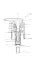
- FIG. 2 is a vertical cross-sectional side view of the first embodiment of the pump-type dispenser according to the present invention, showing a state before an inwardly inclined elastic piece is bent.
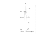
- FIG. 2 is a partial enlarged view of the inwardly collapsing elastic piece shown in FIG. 1 .
- FIG. 10 is a partially enlarged view of an outwardly collapsing elastic piece according to another embodiment of the pump-type dispenser of the present invention.
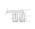
- 2 is a vertical cross-sectional view seen from the side, showing a state in which the head is pressed from the state shown in FIG. 1 and an inwardly collapsing elastic piece is bent.
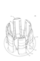
- FIG. 2 is a perspective view of the cap shown in FIG. 1 .
- FIG. 11 is a vertical cross-sectional side view of a second embodiment of a pump-type dispenser according to the present invention, showing a state before an inwardly inclined elastic piece is bent.
- FIG. 6 is a partial enlarged view of the inwardly collapsing elastic piece shown in FIG. 5 .
- FIG. 6B is a partially enlarged view of the periphery of the inclined surface shown in FIG. 6A.
- FIG. 10 is a partially enlarged view of an outwardly collapsing elastic piece according to another embodiment of the pump-type dispenser of the present invention.
- FIG. 7B is a partially enlarged view of the periphery of the inclined surface shown in FIG. 7A.
- FIG. 6 is a vertical cross-sectional view seen from the side, showing a state in which the head is pressed from the state shown in FIG. 5 and the inwardly collapsing elastic pieces are bent.
- FIG. 6 is a perspective view of the cap shown in FIG. 5 .
- the up-down direction refers to the direction along the illustrated central axis O (the central axis of the stem 7a described below), with the side on which the pipe 4 is located being the “bottom” and the side on which the head 12 is located being the "top.”
- the radial direction refers to the direction perpendicular to the central axis O in a plane perpendicular to the central axis O
- the circumferential direction refers to the direction rotating around the central axis O in this plane.
- the pump-type dispenser 100 of this embodiment is used by attaching it to the mouth of a bottle-shaped container (not shown).
- the liquid content dispensed by the pump-type dispenser 100 is, for example, a cosmetic product (such as a milky lotion or toner), shampoo, body soap, hand soap, facial cleanser, etc.
- the pump-type dispenser 100 is composed of a cylinder 1, a valve member 2, a pipe 4, an internal member 5, a piston 6, a cylindrical member 7, a holder 8, a packing 9, a cap 10, a cover 11, a head 12, and a nozzle cover 13.
- the cylinder 1, the valve member 2, the internal member 5, the piston 6, the cylindrical member 7, and the holder 8 are members that constitute the "pump" in this specification.
- the valve member 2, the piston 6, and the packing 9 are made of elastic soft synthetic resin (e.g., polyethylene (LDPE, HDPE, foamed PE)), and the other members are made of hard synthetic resin (e.g., polypropylene (PP), polybutylene terephthalate (PBT), polyacetal (POM), polyketone (POK) resin, etc.).
- LDPE polyethylene
- HDPE high density polyethylene
- PBT polybutylene terephthalate
- POM polyacetal
- POK polyketone
- Each member that constitutes the pump-type dispenser 100 is basically formed in a shape centered on the central axis O.
- the cylinder 1 has a disk-shaped bottom wall 1a with an upwardly protruding central portion, a cylindrical tube wall 1b that stands up from the outer edge of the bottom wall 1a, and a flange wall 1c that extends radially outward from the upper part of the tube wall 1b.
- a through hole (suction port 1d) is provided in the protruding central portion of the bottom wall 1a.
- a cylindrical retaining tube 1e that surrounds the suction port 1d and extends downward to hold the pipe 4 is provided on the underside of the bottom wall 1a.
- a through hole (vent hole 1f) is provided in the tube wall 1b.
- the valve member 2 comprises a base 2a, a valve body portion 2b that covers the suction port 1d and seats on the upper surface of the bottom wall portion 1a, and an elastically deformable connecting piece 2c that connects the base 2a and the valve body portion 2b.
- the valve member 2 functions as a check valve, and when the pressure inside the cylinder 1 is reduced, the valve body portion 2b that has been closing the suction port 1d moves away from the bottom wall portion 1a, opening the suction port 1d.
- the base 2a is cylindrical with a lid and has an opening (not shown) through which the liquid content passes after passing through the suction port 1d.
- the base 2a is fitted and held against the inner circumferential surface of the cylindrical wall portion 1b, so that the valve member 2 is held within the cylinder 1.
- the pipe 4 is hollow, and its upper end is inserted into the retaining tube 1e and is held in place by it.
- the internal member 5 is disposed inside the cylinder 1 and is a member that moves up and down relative to the cylinder 1.
- the internal member 5 comprises a cylindrical connecting tube 5a and a bottom portion 5b that closes the lower end of the connecting tube 5a and extends radially outward.
- the connecting tube 5a is provided with a hole (communication port 5c) that passes through it, and the top surface of the bottom portion 5b is provided with an annular portion 5d that is located radially outward from the connection portion with the connecting tube 5a.
- the piston 6 is inserted through the connecting tube 5a and positioned above the bottom 5b.
- the piston 6 in this embodiment has a circular base 6a.
- An outer sliding piece 6b extending upward and downward from the base 6a is provided on the outer edge of the base 6a.
- the outer sliding piece 6b slidably and liquid-tightly contacts the inner peripheral surface of the tube wall portion 1b.
- An inner sliding piece 6c extending upward and downward from the base 6a is provided on the inner edge of the base 6a.
- the lower part of the inner sliding piece 6c slidably and liquid-tightly contacts the inner peripheral surface of the annular portion 5d, and the upper part slidably and liquid-tightly contacts the inner peripheral surface of the enlarged diameter portion 7b of the tubular member 7, which will be described later.
- the tubular member 7 is a member that is generally tubular.
- the tubular member 7 has a cylindrical stem 7a and an enlarged diameter portion 7b that is connected to the lower end of the stem 7a and has a larger diameter than the stem 7a.
- the holder 8 has a portion located radially outward of the stem 7a and a portion located radially outward of the enlarged diameter portion 7b, and is equipped with a holder base 8a that is fitted and held against the inner peripheral surface of the cylindrical wall portion 1b.
- a flange 8b extending radially outward is provided at the upper end of the holder base 8a. The holder 8 prevents the internal member 5, piston 6, and cylindrical member 7 from slipping out of the cylinder 1.
- the packing 9 is in the shape of a circular ring plate, and is inserted into and held in the cylindrical wall portion 1b of the cylinder 1.
- the packing 9 is sandwiched between the mouth of the container and the flange wall 1c. This prevents problems such as the contents spilling out of the mouth when the container is turned over, for example.
- the cap 10 has a disk-shaped top wall 10a with a through hole in the center.
- a cylindrical peripheral wall 10b extending downward is provided on the outer edge of the top wall 10a.
- the upper part of the inner peripheral surface of the peripheral wall 10b bulges radially inward to fit and hold the flange wall 1c, thereby holding the cylinder 1 in the cap 10.
- the inner peripheral surface of the cap 10 has a female threaded portion 10c that screws into a male threaded portion provided on the mouth of the container, and the cap 10 can be attached to the container by screwing the male threaded portion and the female threaded portion 10c together.
- the outer peripheral surface of the peripheral wall 10b has a rotation prevention recess 10d extending in the vertical direction, as shown in the partial enlarged view of FIG. 1.
- a plurality of rotation prevention recesses 10d are provided at intervals in the circumferential direction.
- the cap 10 also includes plate-shaped inwardly inclined elastic pieces 10e that extend upward from the upper surface of the top wall 10a and are capable of elastically deforming radially inward.
- the inwardly inclined elastic pieces 10e are formed in an arc shape centered on the central axis O in a plan view, and a total of six of them are provided at equal intervals in the circumferential direction (see FIG. 4).
- the outer peripheral surface 10f of the inwardly inclined elastic piece 10e is inclined in a direction away from the inner peripheral surface 10j of the inwardly inclined elastic piece 10e (diametrically outward) from the lower end (root portion 10g) connected to the top wall 10a to the reference line BL that extends parallel to the central axis O.
- the cap 10 of this embodiment is formed by injection molding using a mold, and this mold is basically composed of an upper mold and a lower mold, one of which moves along the reference line BL relative to the other.
- the outer peripheral surface 10f is inclined in the direction of forcible removal relative to the upper mold.
- the length of the inwardly inclined elastic piece 10e (the length from the upper surface of the top wall 10a to the upper end surface of the inwardly inclined elastic piece 10e) is preferably 10 mm or more and 40 mm or less, so that it can be elastically deformed radially inward and so that the size of the pump-type dispenser 100 does not become excessively large.
- the angle at which the outer peripheral surface 10f is inclined with respect to the reference line BL is preferably greater than 0° and less than 3°. If the angle is within this range, the inwardly inclined elastic piece 10e can be released from the mold even if the inclination is in the direction of forced removal.
- the outer peripheral surface of the tip 10h of the inwardly inclined elastic piece 10e is inclined so that the diameter of the tip 10h decreases as it approaches the upper side, and the inclination angle with respect to the reference line BL at this portion is 10° to 45° (approximately 15° in the present embodiment).
- the inner peripheral surface 10j of the inwardly inclined elastic piece 10e of the present embodiment extends in the direction of the draft gradient that is normally set when the piece is released from the mold, and specifically, it is inclined in the direction approaching the outer peripheral surface 10f (diametrically outward) as it moves from the lower end connected to the top wall 10a to the upper end.
- the inclination angle of the inner peripheral surface 10j with respect to the reference line BL is greater than 0° and less than 3° (approximately 1° in the present embodiment).
- the inner peripheral surface 10j may extend parallel to the reference line BL (the angle between the inner peripheral surface 10j and the reference line BL is 0°), or may be inclined at a larger angle than the normally set draft gradient.
- the cover 11 has a cylindrical cover peripheral wall 11a.
- the cover peripheral wall 11a surrounds the peripheral wall 10b and the inwardly inclined elastic piece 10e.
- the lower end of the cover peripheral wall 11a is provided with a stopper protrusion 11b that protrudes radially inward and engages with the lower end of the peripheral wall 10b.
- the inner peripheral surface of the cover peripheral wall 11a is provided with a rib 11c extending in the vertical direction.
- the lower part of the rib 11c engages with the anti-rotation recess 10d, and the cover 11 is held in the cap 10 without rotating.
- the upper part of the rib 11c protrudes radially inward more than the lower part.
- the lower end surface of the upper part contacts the upper surface of the top wall 10a, and the stopper protrusion 11b engages with the lower end of the peripheral wall 10b as described above, so that the cover 11 is held in the cap 10 without falling off.
- the upper end of the cover peripheral wall 11a is provided with an inward flange 11d that extends radially inward.
- the head 12 is cylindrical and has a tubular portion 12a into which the stem 7a is inserted and held in place.
- the upper portion of the tubular portion 12a is provided with a top portion 12b whose upper surface is shaped so as to be concave downwards and which has a passage inside that leads to the tubular portion 12a.
- the top portion 12b is provided with a nozzle 12c which is cylindrical and extends radially outward and leads to a passage provided inside the top portion 12b.
- the tip of the nozzle 12c is provided with a discharge port 12d through which the content liquid is discharged by the pump type discharger 100.
- the head 12 also has an extension 12e that extends downward from the top 12b and the nozzle 12c.
- the extension 12e is cylindrical with the central axis O as its center.
- the lower end (tip) of the extension 12e is inclined so as to narrow radially inward as it extends generally downward.
- the inwardly inclined elastic piece 10e stands upright in the vertical direction, and the lower end of the extension 12e is illustrated as overlapping with the upper end of the inwardly inclined elastic piece 10e, but in reality, the inwardly inclined elastic piece 10e is slightly inclined radially inward so that this overlap is eliminated, and the head 12 moves to its upper limit (rear limit).
- the nozzle cover 13 has a cover body 13a that surrounds the outer periphery and tip of the nozzle 12c.
- the cover body 13a is provided with a cover retaining portion 13b that is C-shaped in a plan view, and the cover retaining portion 13b is retained by the extension portion 12e by moving laterally from the opening of this C-shaped portion toward the extension portion 12e.
- the tip of the extension 12e contacts the inwardly collapsing elastic piece 10e, and the head 12 is in a raised state (the head 12 is retracted from the cap 10).
- the stem 7a When the head 12 is pressed from above to lower it (the head 12 is advanced toward the cap 10), the stem 7a is pressed down together with the head 12 (the stem 7a moves toward the cap 10 along the central axis O). As the stem 7a is pressed down, the bottom 5b also descends via the connecting tube 5a, and the liquid-tight contact between the annular portion 5d and the lower portion of the inner sliding piece 6c is released. When the head 12 is pressed down further, the piston 6 also descends together with the tubular member 7 and internal member 5, and the inside of the cylinder 1 is pressurized.
- the liquid content in the cylinder 1 passes through the communication port 5c, passes through the connecting tube 5a, the stem 7a, the tubular portion 12a, the passage provided inside the top portion 12b, and the inside of the nozzle 12c, and is discharged from the discharge port 12d to the outside world.
- the container (not shown) communicates with the outside world through the vent 1f. This prevents the pressure inside the container from becoming negative even if the liquid contained in the container decreases, preventing the container from being deformed or crushed.
- the extension 12e moves downward while contacting the outer peripheral surface 10f of the inwardly inclined elastic piece 10e, so that the inwardly inclined elastic piece 10e bends radially inward as shown in Figure 3.
- the outer peripheral surface 10f of the inwardly inclined elastic piece 10e is inclined toward the inner peripheral surface 10j from the base portion 10g toward the tip portion 10h, as in the case of a normal draft slope, the extension 12e and the outer peripheral surface 10f will come into increasingly strong contact as the head 12 is pressed down, and the angle at which the inwardly inclined elastic piece 10e falls will increase.
- the outer peripheral surface 10f of the inwardly inclined elastic piece 10e of this embodiment is inclined away from the inner peripheral surface 10j from the base portion 10g toward the tip portion 10h. That is, in the present embodiment, compared to an inwardly inclined elastic piece 10e with an inclined outer peripheral surface 10f so as to have a normal draft angle, the angle at which the inwardly inclined elastic piece 10e falls becomes smaller as the head 12 is pressed down, and therefore the load on the inwardly inclined elastic piece 10e also becomes smaller, making it possible to suppress the effects of settling when repeatedly flexed. Also, because the load on the inwardly inclined elastic piece 10e when it flexes is smaller, excessive force is not required when pressing the head 12.
- the pump-type dispenser 100 of this embodiment can return the head 12 to its original position after discharging the liquid content without using a metal coil spring, and can be used in the same way as a conventional pump-type dispenser.
- the effect of settling caused by repeated bending of the inwardly collapsing elastic piece 10e can be suppressed, preventing the head 12 from becoming difficult to return to its original position when used continuously.
- the pump-type discharger 100 described above can achieve the same effect by using the outwardly inclined elastic piece 10k and the extension portion 12f shown in FIG. 2B instead of the inwardly inclined elastic piece 10e and the extension portion 12e shown in FIG. 2A.
- the outwardly inclined elastic piece 10k like the inwardly inclined elastic piece 10e, is formed in an arc shape centered on the central axis O in a plan view, and a total of six of them are provided at equal intervals in the circumferential direction.
- the inner peripheral surface 10m of the outwardly inclined elastic piece 10k shown in the figure is inclined in a direction away from the outer peripheral surface 10q of the outwardly inclined elastic piece 10k (diametrically inward) from the lower end (root portion 10n) connected to the top wall 10a to the reference line BL that extends parallel to the central axis O. As it moves from the lower end to the upper end (tip portion 10p), the inner peripheral surface 10m of the outwardly inclined elastic piece 10k is inclined in the direction of forcible removal from the mold that forms it.
- the length of the outwardly inclined elastic piece 10k (the length from the upper surface of the top wall 10a to the upper end surface of the outwardly inclined elastic piece 10k), like the length of the inwardly inclined elastic piece 10e, is preferably 10 mm or more and 40 mm or less, and the angle of inclination of the inner peripheral surface 10m with respect to the reference line BL is preferably greater than 0° and less than 3°.
- the inner circumferential surface of the tip 10p of the outwardly inclined elastic piece 10k is inclined so that the diameter decreases as it approaches the upper part, and the inclination angle with respect to the reference line BL at this part is 10° or more and 45° or less (about 15° in this embodiment).
- the outer circumferential surface 10q of the outwardly inclined elastic piece 10k is inclined in a direction approaching the inner circumferential surface 10m (diametrically inward) as it approaches the upper end from the lower end connected to the top wall 10a, and the inclination angle of the outer circumferential surface 10q with respect to the reference line BL is greater than 0° and less than 3° (about 1° in this embodiment).
- the outer circumferential surface 10q may extend parallel to the reference line BL (the angle between the outer circumferential surface 10q and the reference line BL is 0°), or may be inclined at a larger angle than the normally set draft angle.
- the extension 12f is cylindrical and centered on the central axis O, and the lower end (tip) of the extension 12e is inclined so that it narrows radially outward as it extends generally downward.
- the extending portion 12f moves downward while contacting the inner peripheral surface 10m of the outwardly inclined elastic piece 10k, so that the outwardly inclined elastic piece 10k can be bent radially outward.
- the inner peripheral surface 10m of the outwardly inclined elastic piece 10k is inclined in a direction away from the outer peripheral surface 10q as it moves from the base portion 10n to the tip portion 10p.
- the angle at which the head 12 is inclined becomes smaller as the head 12 is pressed down, and therefore the load on the outwardly inclined elastic piece 10k is also smaller, so that the effect of sagging when repeatedly bending can be suppressed.
- the load when the outwardly inclined elastic piece 10k is bent is smaller, excessive force is not required when pressing the head 12.
- Pump type dispenser 100A which is a second embodiment of the pump type dispenser according to the present invention, will be described with reference to Figures 5 to 9.
- Pump type dispenser 100A differs from pump type dispenser 100 described above mainly in the peripheral parts of inwardly collapsing elastic piece 10e and extension part 12e. For this reason, the following description will focus on the differences, and parts that share a basic configuration with pump type dispenser 100 will be given the same reference numerals in the drawings and detailed description will be omitted.
- the cap 10A of this embodiment includes a plate-shaped inwardly inclined elastic piece 10r that extends upward from the upper surface of the top wall 10a and is elastically deformable radially inward.
- FIG. 5 shows the state of the inwardly inclined elastic piece 10r when the head 12A is attached to the stem 7a and the head 12A is at its upper limit (rear limit)
- FIG. 6A shows the state of the inwardly inclined elastic piece 10r before the head 12A is attached to the stem 7a.
- the inwardly inclined elastic piece 10r is slightly inclined radially inward.
- a total of six inwardly inclined elastic pieces 10r are provided at equal intervals in the circumferential direction as shown in FIG. 9.
- the inward-inclined elastic piece 10r has a pair of reinforcing ribs 10s, which are narrower (shorter in circumferential length) than the inward-inclined elastic piece 10r, at both circumferential ends on the radially inner side.
- the thickness (radial length) of the reinforcing rib 10s at the base side is approximately the same as that of the inward-inclined elastic piece 10r, but the thickness gradually becomes thinner in the vertical middle and thinner at the tip.
- the cap 10A also has an outer annular wall 10t located radially outward from the inwardly inclined elastic piece 10r, and an inner annular wall 10u located radially inward from the inwardly inclined elastic piece 10r, as shown in FIG. 5.
- the outer annular wall 10t protrudes upward from the upper surface of the top wall 10a
- the inner annular wall 10u protrudes upward from the upper surface of the top wall 10a and downward from the lower surface.
- the outer annular wall 10t and the inner annular wall 10u increase the rigidity of the top wall 10a, so that the inclination of the inwardly inclined elastic piece 10r can be prevented from changing when the pump-type dispenser 100A is attached to a container (not shown).
- the rigidity of the top wall 10a is increased by the outer annular wall 10t and the inner annular wall 10u, so that the top wall 10a is less likely to deform and the variation in the inclination of the inwardly inclined elastic piece 10r can be suppressed.
- the outer annular wall 10t and the inner annular wall 10u are omitted in Figure 9.
- the head 12A has an extension 12g that extends downward from the top 12b and the nozzle 12c.
- the extension 12g is cylindrical with its center on the central axis O, and the radially inner lower end (tip) of the extension 12g is inclined radially outward as it extends downward.
- the extension 12g contacts the inwardly inclined elastic piece 10r at the upper end of this inclined portion.
- the contact portion 12h the upper end of this inclined portion will be referred to as the contact portion 12h.
- the outer peripheral surface 10r1 of the inwardly inclined elastic piece 10r is basically inclined in a direction away from the inner peripheral surface 10r4 of the inwardly inclined elastic piece 10r (diametrically outward) from the lower end (root portion 10r2) connected to the top wall 10a to the reference line BL that extends parallel to the central axis O. As it moves from the lower end to the upper end (tip portion 10r3), it is inclined.
- This is similar to the inwardly inclined elastic piece 10e shown in Figure 2A, but the inwardly inclined elastic piece 10r further has an inclined surface 10r5 on the outer peripheral surface 10r1.
- the length of the inwardly inclined elastic piece 10r is preferably 10 mm or more and 40 mm or less, and the angle of inclination of the outer peripheral surface 10r1 with respect to the reference line BL is preferably greater than 0° and less than 3°.
- the outer peripheral surface of the tip portion 10r3 is inclined so that its diameter decreases as it approaches the top, and the angle of inclination with respect to the reference line BL at this portion is between 10° and 45° (approximately 15° in this embodiment), and the angle of inclination of the inner peripheral surface 10r4 with respect to the reference line BL is between 0° and 3° (approximately 1° in this embodiment).
- the above-mentioned inclined surface 10r5 will now be described.
- the contact portion 12h of the extension portion 12g comes into contact with the outer peripheral surface 10r1, which is the forward limit contact point P1.
- the line L1 indicates the height at which the forward limit contact point P1 is located.
- the outer peripheral surface 10r1 has an inclined surface 10r5 that starts at an inflection point P2 located within a range of 1 to 3 mm upward (rearward) along the reference line BL from the line L1 where the forward limit contact point P1 is located, and inclines in a direction approaching the inner peripheral surface 10r4 as it moves from the inflection point P2 toward the base portion 10r2.
- the angle at which the inclined surface 10r5 is inclined with respect to the outer peripheral surface 10r1 is angle ⁇ .
- the inclined surface 10r5 extends from the line L1 along the reference line BL to a second inflection point P3 located within a range of 1 to 3 mm downward (forward).
- the outer peripheral surface 10r1 extends approximately vertically along the reference line BL below the second inflection point P3.
- the pump type dispenser 100A of this embodiment As the head 12A is pressed down, the inwardly collapsing elastic piece 10r gradually tilts, which gradually increases the resistance force applied to the finger or the like pressing the head 12A.
- the contact part 12h passes the inflection point P2 and reaches the inclined surface 10r5
- the rate of increase in the resistance force felt up until that point decreases, allowing the user to perceive that the head 12A has reached its lowering limit. Therefore, with the pump type dispenser 100A, it is easy to know that the intended operation is being performed, and variation in the amount of the contents dispensed can be reduced. It has also been confirmed that the pump type dispenser 100A also provides the same effects as those achieved by the pump type dispenser 100 described above.
- the inventors of the present application conducted further research into the inclined surface 10r5 and found that when the angle ⁇ at which the inclined surface 10r5 is inclined relative to the outer peripheral surface 10r1 is between 2° and 5°, the feeling of use is particularly excellent and it is possible to particularly suppress the variation in the amount of the contents dispensed.
- the pump-type dispenser 100A described above can achieve the same effect by using the outwardly inclined elastic piece 10v and the extension portion 12j shown in FIG. 7A instead of the inwardly inclined elastic piece 10r and the extension portion 12g shown in FIG. 6A. Note that, like the inwardly inclined elastic piece 10r, a total of six outwardly inclined elastic pieces 10v are provided at equal intervals around the circumferential direction of the cap 10A.
- the inner peripheral surface 10v1 of the outwardly inclined elastic piece 10v shown in the figure is inclined in a direction (diametrically inward) away from the outer peripheral surface 10v4 of the outwardly inclined elastic piece 10v as it moves from the lower end (root portion 10v2) connected to the top wall 10a to the reference line BL that extends parallel to the central axis O.
- the inner peripheral surface 10v1 of the outwardly inclined elastic piece 10v is inclined in the direction of forcible removal from the mold that forms it.
- the length of the outwardly inclined elastic piece 10v (the length from the upper surface of the top wall 10a to the upper end surface of the outwardly inclined elastic piece 10v) is preferably 10 mm or more and 40 mm or less, similar to the length of the inwardly inclined elastic piece 10r, and the angle of inclination of the inner peripheral surface 10v1 with respect to the reference line BL is preferably greater than 0° and less than 3°.
- the inner circumferential surface of the tip 10v3 of the outwardly inclined elastic piece 10v is inclined so that its diameter decreases as it approaches the upper part, and the angle of inclination with respect to the reference line BL at this portion is 10° or more and 45° or less (approximately 15° in this embodiment), and the angle of inclination of the outer circumferential surface 10v4 with respect to the reference line BL is greater than 0° and 3° or less (approximately 1° in this embodiment).
- the extension portion 12j is cylindrical and centered on the central axis O, and the lower end (tip) of the extension portion 12j is inclined radially inward as it extends downward.
- the upper end of this inclined portion of the extension portion 12j contacts the outwardly falling elastic piece 10v.
- the upper end of this inclined portion will be referred to as the contact portion 12k.
- the line L1 shown in Figures 7A and 7B corresponds to the line L1 shown in Figure 6A. That is, if the forward movement limit contact point P1 is the point where the contact portion 12k of the extension portion 12j contacts the inner peripheral surface 10v1 when the head 12A is pushed down to the lower limit (forward movement limit) toward the cap 10A, the line L1 indicates the height at which the forward movement limit contact point P1 is located.
- the inner peripheral surface 10v1 has an inclined surface 10v5 that starts from an inflection point P2 located within a range of 1 to 3 mm upward (rearward) along the reference line BL from the line L1 where the forward movement limit contact point P1 is located, and inclines in a direction approaching the outer peripheral surface 10v4 as it moves from the inflection point P2 toward the base portion 10v2.
- the angle at which the inclined surface 10v5 is inclined with respect to the inner peripheral surface 10v1 is angle ⁇ .
- the inclined surface 10v5 extends from the line L1 along the reference line BL to a second inflection point P3 located within a range of 1 to 3 mm downward (forward).
- the inner circumferential surface 10v1 extends approximately vertically along the reference line BL below the second inflection point P3.
- the outwardly-inclined elastic piece 10v gradually tilts as the head 12A is pressed down, causing the resistance force applied to the finger or the like pressing the head 12A to gradually increase, but when the contact part 12k passes the inflection point P2 and reaches the inclined surface 10v5, the rate of increase in the resistance force felt up until that point decreases, allowing the user to perceive that the head 12A has reached its lowering limit. Therefore, even in the pump-type dispenser 100A equipped with the outwardly-inclined elastic piece 10v and extension 12j, it is easy to know that the intended operation is being performed, and variation in the amount of the contents dispensed can be reduced.
- the pump described above is only one example, and the present invention also includes cases where other types of pumps are used.
- the number of inwardly inclined elastic pieces 10e and outwardly inclined elastic pieces 10k is not limited to that in the above-described embodiment, and can be changed as appropriate.
- the inwardly inclined elastic pieces 10e and outwardly inclined elastic pieces 10k are not limited to being arc-shaped in plan view as shown in the figure, and may be, for example, linear in plan view.
- the extensions 12e, 12f are not limited to being cylindrical, and may be, for example, rectangular tubular.
- the cap 10, 10A is provided with the inwardly inclined elastic pieces 10e, 10r and the outwardly inclined elastic pieces 10k, 10v, and the head 12, 12A is provided with the extensions 12e, 12f, 12g, 12j, but these may be interchanged and the head 12, 12A may be provided with the inwardly inclined elastic pieces 10e, 10r and the outwardly inclined elastic pieces 10k, 10v, and the cap 10, 10A may be provided with the extensions 12e, 12f, 12g, 12j.
Landscapes
- Engineering & Computer Science (AREA)
- Mechanical Engineering (AREA)
- General Engineering & Computer Science (AREA)
- Closures For Containers (AREA)
Abstract
従来と同じようにして内容液を吐出することが可能であって、更にリサイクル性にも優れるポンプ式吐出器を提案する。 ポンプ式吐出器(100)は、ステム(7a)が進退移動することによって駆動するポンプと、吐出口(12d)を有するとともにステム(7a)に連結するヘッド(12)と、を備え、ヘッド(12)及びキャップの何れか一方に、ヘッド(12)及びキャップの何れか他方に向けて延出された延出部(12e)が設けられ、ヘッド(12)及びキャップの何れか他方に、ヘッド(12)をキャップに向けて前進させた際に延出部(12e)が外周面(10f)に接触して中心軸線(O)に近づく向きに撓む内倒れ弾性片(10e)が設けられ、内倒れ弾性片(10e)の外周面(10f)は、根元部(10g)を起点として中心軸線(O)と平行に延在する基準線(BL)に対し、根元部(10g)から先端部(10h)に向かうにつれて内周面(10j)から離れる向きに傾いている。
Description
本発明は、ポンプ式吐出器に関する。
ポンプ式吐出器として、容器の口部に装着されるキャップと、キャップにより口部に保持されステムが進退移動することによって駆動するポンプと、ステムに連結するヘッドとを備え、ヘッドをキャップに向けて移動させることによって容器内の内容液をヘッドの吐出口から吐出させるものが既知である(例えば特許文献1参照)。
このようなポンプ式吐出器の内部には、特許文献1に示されているように、キャップに向けて移動させたヘッドを初期位置に復帰させるためにコイルスプリングが設けられている。
ところでこのようなポンプ式吐出器は、大部分の部材は合成樹脂製であるものの、コイルスプリングは金属製である。このため使用後に廃棄するにあたって、このままの状態では樹脂品としてリサイクルすることができない。また一般にこの種のポンプ式吐出器では、通常の使用時において部材が外れてしまうことを避けるべく、例えば嵌合等によって部材同士は強固に固定されている。従って、ポンプ式吐出器を分解してコイルスプリングと他の部材とに分別するにも手間を要することとなる。
本発明はこのような問題点を解決することを課題とするものであって、従来と同じようにして内容液を吐出することが可能であって、更にリサイクル性にも優れるポンプ式吐出器を提案することを目的とする。
本発明は、内容液を収容する容器の口部に装着されるキャップと、該キャップにより該口部に保持されステムが進退移動することによって駆動するポンプと、内容液を外界に吐出させる吐出口を有するとともに該ステムに連結するヘッドと、を備え、該ヘッドを該キャップに向けて移動させることによって該容器内の内容液を該吐出口から吐出させるポンプ式吐出器において、
前記ヘッド及び前記キャップの何れか一方に、該ヘッド及び該キャップの何れか他方に向けて延出された延出部が設けられ、
前記ヘッド及び前記キャップの何れか他方に、該ヘッドを該キャップに向けて前進させた際に前記延出部が外周面に接触して前記ステムの中心軸線に近づく向きに撓む内倒れ弾性片が設けられ、
前記内倒れ弾性片の前記外周面は、該内倒れ弾性片の根元部を起点として前記ステムの中心軸線と平行に延在する基準線に対し、該根元部から該内倒れ弾性片の先端部に向かうにつれて該内倒れ弾性片の内周面から離れる向きに傾いているポンプ式吐出器である。
前記ヘッド及び前記キャップの何れか一方に、該ヘッド及び該キャップの何れか他方に向けて延出された延出部が設けられ、
前記ヘッド及び前記キャップの何れか他方に、該ヘッドを該キャップに向けて前進させた際に前記延出部が外周面に接触して前記ステムの中心軸線に近づく向きに撓む内倒れ弾性片が設けられ、
前記内倒れ弾性片の前記外周面は、該内倒れ弾性片の根元部を起点として前記ステムの中心軸線と平行に延在する基準線に対し、該根元部から該内倒れ弾性片の先端部に向かうにつれて該内倒れ弾性片の内周面から離れる向きに傾いているポンプ式吐出器である。
前記外周面が前記基準線に対して傾く角度は、0°より大きく3°以下であることが好ましい。
前記ヘッドを前記キャップに向けて前進限まで前進させた際に前記延出部が前記外周面に接触するところを前進限接触点とする場合、
前記外周面は、前記延出部によって前記内倒れ弾性片が撓む前の状態において前記前進限接触点から前記基準線に沿って後側に1~3mmの範囲内に位置する変曲点を起点として、該変曲点から前記根元部に向かうにつれて前記内周面に近づく向きに傾く傾斜面を有することが好ましい。
前記外周面は、前記延出部によって前記内倒れ弾性片が撓む前の状態において前記前進限接触点から前記基準線に沿って後側に1~3mmの範囲内に位置する変曲点を起点として、該変曲点から前記根元部に向かうにつれて前記内周面に近づく向きに傾く傾斜面を有することが好ましい。
前記傾斜面が前記外周面に対して傾く角度は、2°以上5°以下であることが好ましい。
また本発明は、内容液を収容する容器の口部に装着されるキャップと、該キャップにより該口部に保持されステムが進退移動することによって駆動するポンプと、内容液を外界に吐出させる吐出口を有するとともに該ステムに連結するヘッドと、を備え、該ヘッドを該キャップに向けて移動させることによって該容器内の内容液を該吐出口から吐出させるポンプ式吐出器において、
前記ヘッド及び前記キャップの何れか一方に、該ヘッド及び該キャップの何れか他方に向けて延出された延出部が設けられ、
前記ヘッド及び前記キャップの何れか他方に、該ヘッドを該キャップに向けて前進させた際に前記延出部が内周面に接触して前記ステムの中心軸線から離れる向きに撓む外倒れ弾性片が設けられ、
前記外倒れ弾性片の前記内周面は、該外倒れ弾性片の根元部を起点として前記ステムの中心軸線と平行に延在する基準線に対し、該根元部から該外倒れ弾性片の先端部に向かうにつれて該外倒れ弾性片の外周面から離れる向きに傾いているポンプ式吐出器でもある。
前記ヘッド及び前記キャップの何れか一方に、該ヘッド及び該キャップの何れか他方に向けて延出された延出部が設けられ、
前記ヘッド及び前記キャップの何れか他方に、該ヘッドを該キャップに向けて前進させた際に前記延出部が内周面に接触して前記ステムの中心軸線から離れる向きに撓む外倒れ弾性片が設けられ、
前記外倒れ弾性片の前記内周面は、該外倒れ弾性片の根元部を起点として前記ステムの中心軸線と平行に延在する基準線に対し、該根元部から該外倒れ弾性片の先端部に向かうにつれて該外倒れ弾性片の外周面から離れる向きに傾いているポンプ式吐出器でもある。
前記内周面が前記基準線に対して傾く角度は、0°より大きく3°以下であることが好ましい。
前記ヘッドを前記キャップに向けて前進させた際に前記延出部が前記内周面に接触するところを前進限接触点とする場合、
前記内周面は、前記延出部によって前記外倒れ弾性片が撓む前の状態において前記前進限接触点から前記基準線に沿って後側に1~3mmの範囲内に位置する変曲点を起点として、該変曲点から前記根元部に向かうにつれて前記外周面に近づく向きに傾く傾斜面を有することが好ましい。
前記内周面は、前記延出部によって前記外倒れ弾性片が撓む前の状態において前記前進限接触点から前記基準線に沿って後側に1~3mmの範囲内に位置する変曲点を起点として、該変曲点から前記根元部に向かうにつれて前記外周面に近づく向きに傾く傾斜面を有することが好ましい。
前記傾斜面が前記内周面に対して傾く角度は、2°以上5°以下であることが好ましい。
本発明のポンプ式吐出器によれば、ヘッドをキャップに向けて移動させた際、延出部が内倒れ弾性片の外周面に接触して内倒れ弾性片がステムの中心軸線に近づく向きに撓むため、撓んだ内倒れ弾性片が復元する際にヘッドを初期位置に復帰させることができる。
ここで、内倒れ弾性片を備えるキャップ又はヘッドを金型で形成する際、通常であれば金型からの離型性を考慮して、内倒れ弾性片の外周面は、根元部を起点として離型時に金型が移動する向きに平行に延在する基準線(ステムの中心軸線に対して平行に延在する基準線)に対し、根元部から先端部に向かうにつれて内倒れ弾性片の内周面に近づくように(金型に対して抜き勾配がつくように)傾けて形成される。しかし、内倒れ弾性片の外周面がこの向きに傾いている場合、ヘッドをキャップに向けて移動させていくにつれ、延出部と内倒れ弾性片の外周面とは次第に強く接触することになるため、内倒れ弾性片が傾く角度は大きくなる。一方、本発明における内倒れ弾性片の外周面は、この基準線に対し、根元部から先端部に向かうにつれて内倒れ弾性片の内周面から離れる向きに傾いている。すなわち本発明における内倒れ弾性片は、上述した抜き勾配がつくように外周面が傾いた内倒れ弾性片と比較した場合、ヘッドをキャップに向けて移動させるにつれてステムの中心軸線に近づく向きに倒れる角度が小さくなるため、内倒れ弾性片に及ぼす負荷が小さくなる。ここで、内倒れ弾性片の如き撓み変形可能な弾性片は、比較的大きな負荷でもって繰り返し撓ませるとへたりが生じて復元性が低下することがあるが、上記のように本発明の内倒れ弾性片は、抜き勾配がつくように外周面が傾いた内倒れ弾性片と比較して撓み時における負荷が小さいため、へたりの影響を抑えることができる。また内倒れ弾性片の撓み時の負荷が小さくなることから、ヘッドを押圧する際に力を過剰に要することがない。また本発明のポンプ式吐出器によれば、金属製のコイルスプリングに換えて上記のような内倒れ弾性片を用いているため、従来のポンプ式吐出器のように廃棄にあたって金属部品を分別する必要がなく、また樹脂品として再利用することができることからリサイクル性にも優れる。
上記の効果は、本発明の別の態様のポンプ式吐出器における、延出部が外倒れ弾性片の内周面に接触し、この内周面が、根元部を起点としてステムの中心軸線に対して平行に延在する基準線に対し、根元部から先端部に向かうにつれて外倒れ弾性片の外周面から離れる向きに傾いているものにおいても同様に得られる。
以下、図面を参照しながら本発明に係るポンプ式吐出器の第一実施形態であるポンプ式吐出器100について説明する。なお、本明細書等において上下方向とは、図示した中心軸線O(後述するステム7aの中心軸線)に沿う向きであって、パイプ4が位置する側が「下」であり、ヘッド12が位置する側が「上」である。また径方向とは、中心軸線Oに対して垂直な面内で中心軸線Oと直交する方向であり、周方向とは、この面内で中心軸線Oを中心として周回する方向である。
本実施形態のポンプ式吐出器100は、ボトル状をなす不図示の容器の口部に装着して使用される。ポンプ式吐出器100で吐出させる内容液は、例えば化粧料(一例として乳液や化粧水)、シャンプー、ボディソープ、ハンドソープ、洗顔料等である。
ポンプ式吐出器100は、シリンダー1、弁部材2、パイプ4、内部部材5、ピストン6、筒状部材7、ホルダー8、パッキン9、キャップ10、カバー11、ヘッド12、ノズルカバー13で構成されている。ここでシリンダー1、弁部材2、内部部材5、ピストン6、筒状部材7、及びホルダー8は、本明細書等における「ポンプ」を構成する部材である。また上記の部材のうち、弁部材2、ピストン6、パッキン9は、弾性を有する軟質の合成樹脂(例えばポリエチレン(LDPE、HDPE、発泡PE))により形成されていて、その他の部材は、硬質の合成樹脂(例えばポリプロピレン(PP)・ポリブチレンテレフタレート(PBT)・ポリアセタール(POM)・ポリケトン(POK)樹脂等)で形成されている。そしてポンプ式吐出器100を構成する各部材は、基本的に中心軸線Oを中心とする形状で形作られている。
シリンダー1は、円板状をなしていて中央部が上方に突出する底壁部1aと、底壁部1aの外縁部から起立する円筒状の筒壁部1bと、筒壁部1bの上部から径方向外側に向けて延在するフランジ壁1cを備えている。底壁部1aにおける中央部の突出する部位には、貫通孔(吸込口1d)が設けられている。また底壁部1aの下面には、吸込口1dを取り囲んで下方に向けて延在し、パイプ4を保持する筒状の保持筒1eが設けられている。そして筒壁部1bには、貫通孔(通気口1f)が設けられている。
弁部材2は、基部2aと、吸込口1dを覆って底壁部1aの上面に着座する弁体部2bと、基部2aと弁体部2bとを連結する弾性変形可能な連結片2cとを備えている。弁部材2は逆止弁として機能するものであって、シリンダー1内が減圧状態になると、吸込口1dを閉鎖していた弁体部2bが底壁部1aから離反して吸込口1dを開放させることができる。
基部2aは、本実施形態では有蓋筒状をなしていて、吸込口1dを通過した内容液が通過する不図示の開口を備えている。基部2aは、筒壁部1bの内周面に嵌合保持されるものであり、これにより弁部材2は、シリンダー1内で保持される。
パイプ4は、中空状をなすものであって、上端部は保持筒1eに挿入されてこれに嵌合保持されている。
内部部材5は、シリンダー1の内部に配置され、シリンダー1に対して上下動する部材である。内部部材5は、円筒状をなす連結筒5aと、連結筒5aの下端部を閉鎖するとともに径方向外側に延在する底部5bとを備えている。また連結筒5aには、これを貫通する孔(連通口5c)が設けられていて、底部5bの上面には、連結筒5aとの連結部よりも径方向外側に位置する環状部5dが設けられている。
ピストン6は、連結筒5aに挿通されて底部5bの上方に配置される。本実施形態のピストン6は、円環状の基部6aを備えている。基部6aの外縁部には、基部6aから上方及び下方に向けて延在する外側摺動片6bが設けられている。外側摺動片6bは、筒壁部1bの内周面に対して摺動可能に液密に当接するものである。そして基部6aの内縁部には、基部6aから上方及び下方に向けて延在する内側摺動片6cが設けられている。内側摺動片6cは、その下部は環状部5dの内周面に対して摺動可能に液密に当接し、その上部は筒状部材7における後述する拡径部7bの内周面に対して摺動可能に液密に当接する。
筒状部材7は、全体的に筒状をなす部材である。筒状部材7は、円筒状をなすステム7aと、ステム7aの下端部に連結するとともにステム7aよりも大径になる拡径部7bを備えている。ステム7aの内側に連結筒5aを挿入すると両者は嵌合されるため、内部部材5と筒状部材7は、シリンダー1に対して一体的に移動する。
ホルダー8は、ステム7aの径方向外側に位置する部位と拡径部7bの径方向外側に位置する部位を持ち、筒壁部1bの内周面に嵌合保持されるホルダー基部8aを備えている。ホルダー基部8aの上端部には、径方向外側に向けて延在するフランジ8bが設けられている。ホルダー8によって、内部部材5、ピストン6、筒状部材7のシリンダー1からの抜け出しを防止している。
パッキン9は、円環板状をなすものであって、シリンダー1の筒壁部1bに挿通されてこれに嵌合保持されている。ポンプ式吐出器100を不図示の容器に取り付けた際、パッキン9は容器の口部とフランジ壁1cに挟持される。これにより、例えば容器を倒した際に内容液が口部から溢れる等の不具合が防止される。
キャップ10は、円板状をなしていて中央部に貫通孔を備える天壁10aを備えている。天壁10aの外縁部には、下方に向けて延在する円筒状の周壁10bが設けられている。周壁10bの内周面における上部は、径方向内側に向けて膨出してフランジ壁1cを嵌合保持することが可能であって、これによりシリンダー1は、キャップ10に保持される。またキャップ10の内周面には、容器の口部に設けた雄ねじ部に螺合する雌ねじ部10cが設けられていて、雄ねじ部と雌ねじ部10cとを螺合させることにより、キャップ10を容器に装着することができる。そして周壁10bの外周面には、図1の部分拡大図に示すように、上下方向に延在する回り止め凹部10dが設けられている。回り止め凹部10dは、周方向に間隔をあけて複数設けられている。
またキャップ10は、天壁10aの上面から上方に向けて延在し、径方向内側に向けて弾性変形可能な板状の内倒れ弾性片10eを備えている。本実施形態の内倒れ弾性片10eは、平面視において中心軸線Oを中心として円弧状に形作られるものであり、周方向に等間隔で合計6個設けられている(図4参照)。
ここで、図2Aを参照しながら内倒れ弾性片10eについて詳細に説明する。内倒れ弾性片10eの外周面10fは、天壁10aにつながる下端部(根元部10g)を起点として中心軸線Oと平行に延在する基準線BLに対し、下端部から上端部(先端部10h)に向かうにつれて内倒れ弾性片10eの内周面10jから離れる向き(径方向外側)に傾いている。本実施形態のキャップ10は、金型を用いた射出成形によって形成されていて、この金型は、基本的には一方が他方に対して基準線BLに沿って移動する上型と下型により構成されている。すなわち内倒れ弾性片10eの外形が上型で形作られるとする場合、外周面10fは上型に対して無理抜き方向に勾配がつけられた状態にある。内倒れ弾性片10eの長さ(天壁10aの上面から内倒れ弾性片10eの上端面までの長さ)は、径方向内側に向けて弾性変形可能であること、またポンプ式吐出器100のサイズが過大にならないことを考慮すると、10mm以上で40mm以下であることが好ましい。また外周面10fが基準線BLに対して傾く角度は、0°より大きく3°以下であることが好ましい。この範囲であれば、無理抜き方向につけられた勾配であっても、内倒れ弾性片10eを金型から離型させることが可能である。
なお本実施形態の内倒れ弾性片10eにおいて、先端部10hの外周面は、上方に向かうにつれて縮径するように傾いていて、この部位での基準線BLに対して傾く角度は、10°以上45°以下(本実施形態では約15°)である。また本実施形態の内倒れ弾性片10eの内周面10jは、金型から離型させる際に通常設定される抜き勾配の向きに延在していて、具体的には天壁10aにつながる下端部から上端部に向かうにつれて外周面10fに近づく向き(径方向外側)に傾いている。また内周面10jが基準線BLに対して傾く角度は、0°より大きく3°以下(本実施形態では約1°)である。なお内周面10jは、基準線BLと平行に延在していてもよいし(内周面10jと基準線BLとの角度は0°)、通常設定される抜き勾配の角度より大きく傾いていてもよい。
カバー11は、円筒状になるカバー周壁11aを備えている。カバー周壁11aは、周壁10bと内倒れ弾性片10eを取り囲んでいる。カバー周壁11aの下端部には、径方向内側に向けて突出して周壁10bの下端部に係合する抜け止め凸部11bが設けられている。カバー周壁11aの内周面には、上下方向に延在するリブ11cが設けられている。リブ11cの下部は回り止め凹部10dに係合していて、カバー11はキャップ10に回り止め保持される。リブ11cの上部は、下部よりも径方向内側に突出している。そして、この上部の下端面が天壁10aの上面に接触し、上記のように周壁10bの下端部に抜け止め凸部11bが係合することにより、カバー11はキャップ10に抜け止め保持される。カバー周壁11aの上端部には、径方向内側に向けて延在する内向きフランジ11dが設けられている。
ヘッド12は、円筒状をなし、内側にステム7aが挿入されてこれに嵌合保持される筒状部12aを備えている。筒状部12aの上部には、上面が下方に凹むように形作られ、内部に筒状部12aに通じる通路を有する頂部12bが設けられている。頂部12bには、円筒状をなしていて径方向外側に向けて延在し、頂部12bの内部に設けた通路に通じるノズル12cが設けられている。ノズル12cの先端には、ポンプ式吐出器100によって内容液が吐出される吐出口12dが設けられている。
またヘッド12は、頂部12b及びノズル12cから下方に向けて延出された延出部12eを備えている。本実施形態の延出部12eは、中心軸線Oを中心とする円筒状である。また延出部12eの下端部(先端部)は、図1に示すように、概ね下方に向かうにつれて径方向内側に狭まるように傾斜している。なお図1では、内倒れ弾性片10eは上下方向に起立していて、内倒れ弾性片10eの上端部に対して延出部12eの下端部が重なるように図示したが、実際にはこの重なりが解消されるように、内倒れ弾性片10eは径方向内側に向けて若干傾いた状態にあって、ヘッド12は上昇限(後退限)まで移動している。
ノズルカバー13は、ノズル12cの外周部及び先端部を取り囲むカバー本体部13aを備えている。カバー本体部13aには、平面視でC字状になるカバー保持部13bが設けられていて、このC字状になる部位の開口から延出部12eに向けて横方向に移動させることにより、カバー保持部13bは延出部12eに保持される。
このような部材によって構成されるポンプ式吐出器100は、図1に示すようにヘッド12を押圧する前の状態においては、内倒れ弾性片10eに延出部12eの先端部が接触し、ヘッド12は上昇した状態(ヘッド12はキャップ10から後退した状態)にある。
そしてヘッド12を上方から押圧してヘッド12を下降させる(ヘッド12をキャップ10に向けて前進させる)と、ステム7aがヘッド12とともに押し下げられる(中心軸線Oに沿ってステム7aがキャップ10に向けて移動する)。またステム7aが押し下げられるに伴い、連結筒5aを介して底部5bも下降するため、環状部5dと内側摺動片6cの下部との液密な当接が解除される。そしてヘッド12を更に押し下げていくと、筒状部材7及び内部部材5とともにピストン6も下降して、シリンダー1の内部が加圧される。このためシリンダー1内の内容液は、連通口5cを通過し、連結筒5a、ステム7a、筒状部12a、頂部12bの内部に設けた通路、及びノズル12cの内側を通って吐出口12dから外界に吐出される。なお、ヘッド12を押圧してピストン6が通気口1fよりも下降すると、不図示の容器は、通気口1fを介して外界と連通する。これにより容器に収容した内容液が減っても容器内は負圧化されず、容器がつぶれるように変形する不具合が防止される。
またヘッド12が押し下げられると、延出部12eが内倒れ弾性片10eの外周面10fに接触しながら下方に移動するため、図3に示すように内倒れ弾性片10eは径方向内側に撓んでいく。ところで、内倒れ弾性片10eにおける外周面10fが、通常の抜き勾配がつくように根元部10gから先端部10hに向かうにつれて内周面10jに近づく向きに傾いていると、ヘッド12を押し下げていくにつれて延出部12eと外周面10fとは次第に強く接触することになるため、内倒れ弾性片10eが倒れる角度は大きくなる。一方、本実施形態の内倒れ弾性片10eにおける外周面10fは、根元部10gから先端部10hに向かうにつれて内周面10jから離れる向きに傾いている。すなわち本実施形態の内倒れ弾性片10eは、通常の抜き勾配がつくように外周面10fが傾いた内倒れ弾性片10eと比較した場合、ヘッド12を押し下げていくにつれて内倒れ弾性片10eが倒れる角度は小さくなり、それ故、内倒れ弾性片10eに及ぼす負荷も小さくなるため、繰り返し撓ませた際のへたりの影響を抑えることができる。また内倒れ弾性片10eの撓み時の負荷が小さくなるため、ヘッド12を押圧する際に力を過剰に要することがない。
その後、ヘッド12への押圧を解除すると、弾性変形していた内倒れ弾性片10eの復元力がヘッド12に作用し、ヘッド12は上昇し始める。これに伴い、環状部5dに対して内側摺動片6cの下部が再び液密に当接しつつ、ピストン6が内部部材5とともに上昇するため、シリンダー1の内部が減圧される。これにより、弁体部2bが底壁部1aから離反して吸込口1dが開放されて、パイプ4を通して容器内の内容液をシリンダー1内に吸引させることができる。
このように本実施形態のポンプ式吐出器100によれば、金属製のコイルスプリングを用いずとも、内容液を吐出させた後のヘッド12を復帰させることができ、従来のポンプ式吐出器と同じように使用することができる。また、上述したように内倒れ弾性片10eを繰り返し撓ませた際のへたりの影響を抑えることができるため、継続して使用した際にヘッド12が復帰しづらくなる不具合を防止することができる。
上述したポンプ式吐出器100は、図2Aに示した内倒れ弾性片10eと延出部12eに換えて、図2Bに示した外倒れ弾性片10kと延出部12fを用いても同様の効果が得られる。なお外倒れ弾性片10kは、内倒れ弾性片10eと同様に、平面視において中心軸線Oを中心として円弧状に形作られるものであり、周方向に等間隔で合計6個設けられている。
図示した外倒れ弾性片10kの内周面10mは、天壁10aにつながる下端部(根元部10n)を起点として中心軸線Oと平行に延在する基準線BLに対し、下端部から上端部(先端部10p)に向かうにつれて外倒れ弾性片10kの外周面10qから離れる向き(径方向内側)に傾いている。すなわち外倒れ弾性片10kの内周面10mは、これを形成する金型に対して無理抜き方向に勾配がつけられた状態にある。外倒れ弾性片10kの長さ(天壁10aの上面から外倒れ弾性片10kの上端面までの長さ)も内倒れ弾性片10eの長さと同様に、10mm以上で40mm以下であることが好ましく、また内周面10mが基準線BLに対して傾く角度は、0°より大きく3°以下であることが好ましい。
なお外倒れ弾性片10kにおける先端部10pの内周面は、上方に向かうにつれて縮径するように傾いていて、この部位での基準線BLに対して傾く角度は、10°以上45°以下(本実施形態では約15°)である。また外倒れ弾性片10kの外周面10qは、天壁10aにつながる下端部から上端部に向かうにつれて内周面10mに近づく向き(径方向内側)に傾いていて、外周面10qが基準線BLに対して傾く角度は、0°より大きく3°以下(本実施形態では約1°)である。なお外周面10qは、基準線BLと平行に延在していてもよいし(外周面10qと基準線BLとの角度は0°)、通常設定される抜き勾配の角度より大きく傾いていてもよい。
そして延出部12fは、中心軸線Oを中心とする円筒状であって、延出部12eの下端部(先端部)は、概ね下方に向かうにつれて径方向外側に狭まるように傾斜している。
このような外倒れ弾性片10kと延出部12fを備えるポンプ式吐出器100において、ヘッド12が押し下げられると、延出部12fが外倒れ弾性片10kの内周面10mに接触しながら下方に移動するため、外倒れ弾性片10kを径方向外側に撓ませることができる。ここで外倒れ弾性片10kの内周面10mは、根元部10nから先端部10pに向かうにつれて外周面10qから離れる向きに傾いている。すなわち本実施形態の外倒れ弾性片10kは、通常の抜き勾配がつくように内周面10mが傾いた外倒れ弾性片10kと比較した場合、ヘッド12を押し下げていくにつれて倒れる角度は小さくなり、それ故、外倒れ弾性片10kに及ぼす負荷も小さくなるため、繰り返し撓ませた際のへたりの影響を抑えることができる。また外倒れ弾性片10kの撓み時の負荷が小さくなるため、ヘッド12を押圧する際に力を過剰に要することがない。
次に図5~図9を参照しながら本発明に係るポンプ式吐出器の第二実施形態であるポンプ式吐出器100Aについて説明する。ポンプ式吐出器100Aは、上述したポンプ式吐出器100に対して、主に内倒れ弾性片10eと延出部12eの周辺部分が相違する。このため以下では相異点を中心に説明することとし、ポンプ式吐出器100と基本的な構成が共通する部分については図面に同一の符号を付して詳細な説明は省略する。
図5に示すように本実施形態のキャップ10Aは、天壁10aの上面から上方に向けて延在し、径方向内側に向けて弾性変形可能な板状の内倒れ弾性片10rを備えている。ここで図5は、ヘッド12Aをステム7aに取り付けてヘッド12Aが上昇限(後退限)に位置するときの内倒れ弾性片10rの状態を示し、図6Aは、ヘッド12Aをステム7aに取り付ける前の内倒れ弾性片10rの状態を示している。図5に示すようにヘッド12Aが上昇限に位置するとき、内倒れ弾性片10rは径方向内側に向けて若干傾いた状態にある。本実施形態の内倒れ弾性片10rは、図9に示すように周方向に等間隔で合計6個設けられている。
図5、図9に示すように内倒れ弾性片10rは、内倒れ弾性片10rよりも幅が狭い(周方向長さが短い)補強リブ10sを、径方向内側における周方向両端部に一対備えている。補強リブ10sは、図示したように根元側に位置する部分の厚み(径方向長さ)は内倒れ弾性片10rと同程度の厚みである一方、上下方向中間部で厚みが徐々に薄くなり、先端部に位置する部分では厚みは薄くなっている。
またキャップ10Aは、図5に示すように内倒れ弾性片10rよりも径方向外側に位置する外側環状壁10tと、内倒れ弾性片10rよりも径方向内側に位置する内側環状壁10uとを備えている。外側環状壁10tは、天壁10aの上面から上方に向けて突出し、内側環状壁10uは、天壁10aの上面から上方に向けて突出するとともに下面から下方に向けて突出している。外側環状壁10tと内側環状壁10uによって天壁10aの剛性が高められるため、ポンプ式吐出器100Aを不図示の容器に取り付けた際に内倒れ弾性片10rの傾きが変わることを防止することができる。すなわち、容器の雄ねじ部に対して雌ねじ部10cを強く締め込むと、天壁10aにはパッキン9とフランジ壁1cを介して容器の口部上端面から強い力が加わり、締め込みが弱いと天壁10aに加わる力は弱くなる。従って、雄ねじ部に対する雌ねじ部10cの締め込み具合によって天壁10aに加わる力が変動し、これにより内倒れ弾性片10rの傾きが変わってしまうことになる。一方、本実施形態では、外側環状壁10tと内側環状壁10uによって天壁10aの剛性が高められているため、天壁10aが変形し難くなって内倒れ弾性片10rの傾きの変動を抑制することができる。なお図9においては、外側環状壁10tと内側環状壁10uを省略している。
そしてヘッド12Aは、頂部12b及びノズル12cから下方に向けて延出された延出部12gを備えている。本実施形態の延出部12gは、中心軸線Oを中心とする円筒状であって、延出部12gの径方向内側の下端部(先端部)は、下方に向かうにつれて径方向外側に向けて傾斜している。図5に示すように延出部12gは、この傾斜する部位の上端部で内倒れ弾性片10rに接触する。以下、この傾斜する部位の上端部を接触部12hと称する。
ここで、本実施形態の内倒れ弾性片10rについて図6A、図6Bを参照しながら詳細に説明する。内倒れ弾性片10rの外周面10r1は、基本的には天壁10aにつながる下端部(根元部10r2)を起点として中心軸線Oと平行に延在する基準線BLに対し、下端部から上端部(先端部10r3)に向かうにつれて内倒れ弾性片10rの内周面10r4から離れる向き(径方向外側)に傾いている。この点は図2Aに示した内倒れ弾性片10eと同様であるが、内倒れ弾性片10rは、更に外周面10r1に傾斜面10r5を備えている。なお、内倒れ弾性片10rも上述した内倒れ弾性片10eと同様に、長さは10mm以上で40mm以下であることが好ましく、外周面10r1が基準線BLに対して傾く角度は、0°より大きく3°以下であることが好ましい。そして先端部10r3の外周面は、上方に向かうにつれて縮径するように傾いていて、この部位での基準線BLに対して傾く角度は、10°以上45°以下(本実施形態では約15°)であり、内周面10r4が基準線BLに対して傾く角度は、0°より大きく3°以下(本実施形態では約1°)である。
上述した傾斜面10r5について説明する。図8に示すように、ヘッド12Aをキャップ10Aに向けて下降限(前進限)まで押し下げた際に延出部12gの接触部12hが外周面10r1に接触するところを前進限接触点P1とする。ここで、図6A、図6Bに示した内倒れ弾性片10rが延出部12gによって撓む前の状態を示した図において、ラインL1は、前進限接触点P1が位置するところでの高さを示している。外周面10r1は、この前進限接触点P1が位置するラインL1から基準線BLに沿って上側に(後側に)1~3mmの範囲内に位置する変曲点P2を起点として、変曲点P2から根元部10r2に向かうにつれて内周面10r4に近づく向きに傾く傾斜面10r5を有している。ここで、傾斜面10r5が外周面10r1に対して傾く角度を角度θとする。傾斜面10r5は、ラインL1から基準線BLに沿って下側に(前側に)1~3mmの範囲内に位置する第2変曲点P3まで延在している。なお外周面10r1は、第2変曲点P3から下方においては、基準線BLに沿って略垂直に延在している。
ところで本願発明者が検討を重ねたところ、ヘッド12Aの如き操作部を押圧して合成樹脂製の弾性片を撓ませる場合は、上述した特許文献1に示されている如き金属製のコイルスプリングを用いる場合に比して、押圧時に指等に伝わる抵抗力の上昇率が大きくなる傾向があった。このため、押圧した操作部が下降限に達しても、使用者によっては気づきにくい場合があった。また抵抗力の上昇率が大きくなることから、使用者によっては下降限に達する前に操作部の押圧を停止することがあり、これにより内容物の吐出量がばらつくおそれがあった。
一方、本実施形態のポンプ式吐出器100Aは、ヘッド12Aを押し下げていくにつれて内倒れ弾性片10rは次第に傾き、これによりヘッド12Aを押圧する指等に加わる抵抗力は次第に大きくなるが、接触部12hが変曲点P2を超えて傾斜面10r5に至ると、それまでに感じていた抵抗力の上昇率が下がるため、使用者はヘッド12Aが下降限に達したことを知覚することができる。従ってポンプ式吐出器100Aによれば、意図した操作を行っていることが分かりやすく、また内容物の吐出量のばらつきも抑えることができる。またポンプ式吐出器100Aにおいても、上述したポンプ式吐出器100で発揮される効果と同様の効果が得られることが確認された。
そして本願発明者が傾斜面10r5について更に検討を重ねたところ、傾斜面10r5が外周面10r1に対して傾く角度θが2°以上5°以下である場合には、使用感が特に優れ、また内容物の吐出量のばらつきも特に抑制することが可能であった。
上述したポンプ式吐出器100Aは、図6Aに示した内倒れ弾性片10rと延出部12gに換えて、図7Aに示した外倒れ弾性片10vと延出部12jを用いても同様の効果が得られる。なお外倒れ弾性片10vは、内倒れ弾性片10rと同様に、キャップ10Aに対して周方向に等間隔で合計6個設けられている。
図示した外倒れ弾性片10vの内周面10v1は、天壁10aにつながる下端部(根元部10v2)を起点として中心軸線Oと平行に延在する基準線BLに対し、下端部から上端部(先端部10v3)に向かうにつれて外倒れ弾性片10vの外周面10v4から離れる向き(径方向内側)に傾いている。すなわち外倒れ弾性片10vの内周面10v1は、これを形成する金型に対して無理抜き方向に勾配がつけられた状態にある。外倒れ弾性片10vの長さ(天壁10aの上面から外倒れ弾性片10vの上端面までの長さ)も内倒れ弾性片10rの長さと同様に、10mm以上で40mm以下であることが好ましく、また内周面10v1が基準線BLに対して傾く角度は、0°より大きく3°以下であることが好ましい。そして外倒れ弾性片10vにおける先端部10v3の内周面は、上方に向かうにつれて縮径するように傾いていて、この部位での基準線BLに対して傾く角度は、10°以上45°以下(本実施形態では約15°)であり、外周面10v4が基準線BLに対して傾く角度は、0°より大きく3°以下(本実施形態では約1°)である。
そして延出部12jは、中心軸線Oを中心とする円筒状であって、延出部12jの下端部(先端部)は、下方に向かうにつれて径方向内側に向けて傾斜している。なお延出部12jは、この傾斜する部位の上端部で外倒れ弾性片10vに接触する。以下、この傾斜する部位の上端部を接触部12kと称する。
ここで、内周面10v1に設けた傾斜面10v5について説明する。図7A、図7Bに示したラインL1は、図6Aに示したラインL1に対応するものである。すなわち、ヘッド12Aをキャップ10Aに向けて下降限(前進限)まで押し下げた際に延出部12jの接触部12kが内周面10v1に接触するところを前進限接触点P1とする場合、ラインL1は、前進限接触点P1が位置するところでの高さを示している。内周面10v1は、この前進限接触点P1が位置するラインL1から基準線BLに沿って上側に(後側に)1~3mmの範囲内に位置する変曲点P2を起点として、変曲点P2から根元部10v2に向かうにつれて外周面10v4に近づく向きに傾く傾斜面10v5を有している。ここで、傾斜面10v5が内周面10v1に対して傾く角度を角度θとする。傾斜面10v5は、ラインL1から基準線BLに沿って下側に(前側に)1~3mmの範囲内に位置する第2変曲点P3まで延在している。なお内周面10v1は、第2変曲点P3から下方においては、基準線BLに沿って略垂直に延在している。
このような外倒れ弾性片10vと延出部12jを備えるポンプ式吐出器100Aにおいても、ヘッド12Aを押し下げていくにつれて外倒れ弾性片10vは次第に傾き、これによりヘッド12Aを押圧する指等に加わる抵抗力は次第に大きくなるが、接触部12kが変曲点P2を超えて傾斜面10v5に至ると、それまでに感じていた抵抗力の上昇率が下がるため、使用者はヘッド12Aが下降限に達したことを知覚することができる。従って外倒れ弾性片10vと延出部12jを備えるポンプ式吐出器100Aにおいても、意図した操作を行っていることが分かりやすく、また内容物の吐出量のばらつきも抑えることができる。
そして傾斜面10v5についても検討を重ねたところ、傾斜面10v5が内周面10v1に対して傾く角度θが2°以上5°以下である場合には、使用感が特に優れ、また内容物の吐出量のばらつきも特に抑制することが可能であった。
以上、本発明の一実施形態について説明したが、本発明は係る特定の実施形態に限定されるものではなく、上記の説明で特に限定しない限り、特許請求の範囲に記載された本発明の趣旨の範囲内において、種々の変形・変更が可能である。例えば上述した実施形態の構成は、適宜追加、削除が可能であり、また一の実施形態の構成を他の実施形態に設けることも可能である。また、上記の実施形態における効果は、本発明から生じる効果を例示したに過ぎず、本発明による効果が上記の効果に限定されることを意味するものではない。
例えば上述したポンプは一例であって、他の形式のポンプを採用した場合も本発明に含まれる。そして、内倒れ弾性片10eと外倒れ弾性片10kの数は、上述した実施形態に限られるものではなく、適宜変更可能である。また内倒れ弾性片10eと外倒れ弾性片10kは、図示したように平面視で円弧状になるものに限られず、例えば平面視で直線状になるものでもよい。また延出部12e、12fは円筒状になるものに限られず、例えば角筒状になるものでもよい。
また上述した実施形態では、キャップ10、10Aに内倒れ弾性片10e、10rや外倒れ弾性片10k、10vを設け、ヘッド12、12Aに延出部12e、12f、12g、12jを設けたが、相互に入れ替えてヘッド12、12Aに内倒れ弾性片10e、10rや外倒れ弾性片10k、10vを設け、キャップ10、10Aに延出部12e、12f、12g、12jを設けてもよい。
1:シリンダー
1a:底壁部
1b:筒壁部
1c:フランジ壁
1d:吸込口
1e:保持筒
1f:通気口
2:弁部材
2a:基部
2b:弁体部
2c:連結片
4:パイプ
5:内部部材
5a:連結筒
5b:底部
5c:連通口
5d:環状部
6:ピストン
6a:基部
6b:外側摺動片
6c:内側摺動片
7:筒状部材
7a:ステム
7b:拡径部
8:ホルダー
8a:ホルダー基部
8b:フランジ
9:パッキン
10、10A:キャップ
10a:天壁
10b:周壁
10c:雌ねじ部
10d:回り止め凹部
10e:内倒れ弾性片
10f:外周面(内倒れ弾性片の外周面)
10g:根元部(内倒れ弾性片の根元部)
10h:先端部(内倒れ弾性片の先端部)
10j:内周面(内倒れ弾性片の内周面)
10k:外倒れ弾性片
10m:内周面(外倒れ弾性片の内周面)
10n:根元部(外倒れ弾性片の根元部)
10p:先端部(外倒れ弾性片の先端部)
10q:外周面(外倒れ弾性片の外周面)
10r:内倒れ弾性片
10r1:外周面(内倒れ弾性片の外周面)
10r2:根元部(内倒れ弾性片の根元部)
10r3:先端部(内倒れ弾性片の先端部)
10r4:内周面(内倒れ弾性片の内周面)
10r5:傾斜面
10s:補強リブ
10t:外側環状壁
10u:内側環状壁
10v:外倒れ弾性片
10v1:内周面(外倒れ弾性片の内周面)
10v2:根元部(外倒れ弾性片の根元部)
10v3:先端部(外倒れ弾性片の先端部)
10v4:外周面(外倒れ弾性片の外周面)
10v5:傾斜面
11:カバー
11a:カバー周壁
11b:抜け止め凸部
11c:リブ
11d:内向きフランジ
12、12A:ヘッド
12a:筒状部
12b:頂部
12c:ノズル
12d:吐出口
12e:延出部
12f:延出部
12g:延出部
12h:接触部
12j:延出部
12k:接触部
13:ノズルカバー
13a:カバー本体部
13b:カバー保持部
100、100A:ポンプ式吐出器
BL:基準線
O:中心軸線
L1:ライン
P1:前進限接触点
P2:変曲点
P3:第2変曲点
1a:底壁部
1b:筒壁部
1c:フランジ壁
1d:吸込口
1e:保持筒
1f:通気口
2:弁部材
2a:基部
2b:弁体部
2c:連結片
4:パイプ
5:内部部材
5a:連結筒
5b:底部
5c:連通口
5d:環状部
6:ピストン
6a:基部
6b:外側摺動片
6c:内側摺動片
7:筒状部材
7a:ステム
7b:拡径部
8:ホルダー
8a:ホルダー基部
8b:フランジ
9:パッキン
10、10A:キャップ
10a:天壁
10b:周壁
10c:雌ねじ部
10d:回り止め凹部
10e:内倒れ弾性片
10f:外周面(内倒れ弾性片の外周面)
10g:根元部(内倒れ弾性片の根元部)
10h:先端部(内倒れ弾性片の先端部)
10j:内周面(内倒れ弾性片の内周面)
10k:外倒れ弾性片
10m:内周面(外倒れ弾性片の内周面)
10n:根元部(外倒れ弾性片の根元部)
10p:先端部(外倒れ弾性片の先端部)
10q:外周面(外倒れ弾性片の外周面)
10r:内倒れ弾性片
10r1:外周面(内倒れ弾性片の外周面)
10r2:根元部(内倒れ弾性片の根元部)
10r3:先端部(内倒れ弾性片の先端部)
10r4:内周面(内倒れ弾性片の内周面)
10r5:傾斜面
10s:補強リブ
10t:外側環状壁
10u:内側環状壁
10v:外倒れ弾性片
10v1:内周面(外倒れ弾性片の内周面)
10v2:根元部(外倒れ弾性片の根元部)
10v3:先端部(外倒れ弾性片の先端部)
10v4:外周面(外倒れ弾性片の外周面)
10v5:傾斜面
11:カバー
11a:カバー周壁
11b:抜け止め凸部
11c:リブ
11d:内向きフランジ
12、12A:ヘッド
12a:筒状部
12b:頂部
12c:ノズル
12d:吐出口
12e:延出部
12f:延出部
12g:延出部
12h:接触部
12j:延出部
12k:接触部
13:ノズルカバー
13a:カバー本体部
13b:カバー保持部
100、100A:ポンプ式吐出器
BL:基準線
O:中心軸線
L1:ライン
P1:前進限接触点
P2:変曲点
P3:第2変曲点
Claims (8)
- 内容液を収容する容器の口部に装着されるキャップと、該キャップにより該口部に保持されステムが進退移動することによって駆動するポンプと、内容液を外界に吐出させる吐出口を有するとともに該ステムに連結するヘッドと、を備え、該ヘッドを該キャップに向けて移動させることによって該容器内の内容液を該吐出口から吐出させるポンプ式吐出器において、
前記ヘッド及び前記キャップの何れか一方に、該ヘッド及び該キャップの何れか他方に向けて延出された延出部が設けられ、
前記ヘッド及び前記キャップの何れか他方に、該ヘッドを該キャップに向けて前進させた際に前記延出部が外周面に接触して前記ステムの中心軸線に近づく向きに撓む内倒れ弾性片が設けられ、
前記内倒れ弾性片の前記外周面は、該内倒れ弾性片の根元部を起点として前記ステムの中心軸線と平行に延在する基準線に対し、該根元部から該内倒れ弾性片の先端部に向かうにつれて該内倒れ弾性片の内周面から離れる向きに傾いているポンプ式吐出器。 - 前記外周面が前記基準線に対して傾く角度は、0°より大きく3°以下である請求項1に記載のポンプ式吐出器。
- 前記ヘッドを前記キャップに向けて前進限まで前進させた際に前記延出部が前記外周面に接触するところを前進限接触点とする場合、
前記外周面は、前記延出部によって前記内倒れ弾性片が撓む前の状態において前記前進限接触点から前記基準線に沿って後側に1~3mmの範囲内に位置する変曲点を起点として、該変曲点から前記根元部に向かうにつれて前記内周面に近づく向きに傾く傾斜面を有する請求項1に記載のポンプ式吐出器。 - 前記傾斜面が前記外周面に対して傾く角度は、2°以上5°以下である請求項3に記載のポンプ式吐出器。
- 内容液を収容する容器の口部に装着されるキャップと、該キャップにより該口部に保持されステムが進退移動することによって駆動するポンプと、内容液を外界に吐出させる吐出口を有するとともに該ステムに連結するヘッドと、を備え、該ヘッドを該キャップに向けて移動させることによって該容器内の内容液を該吐出口から吐出させるポンプ式吐出器において、
前記ヘッド及び前記キャップの何れか一方に、該ヘッド及び該キャップの何れか他方に向けて延出された延出部が設けられ、
前記ヘッド及び前記キャップの何れか他方に、該ヘッドを該キャップに向けて前進させた際に前記延出部が内周面に接触して前記ステムの中心軸線から離れる向きに撓む外倒れ弾性片が設けられ、
前記外倒れ弾性片の前記内周面は、該外倒れ弾性片の根元部を起点として前記ステムの中心軸線と平行に延在する基準線に対し、該根元部から該外倒れ弾性片の先端部に向かうにつれて該外倒れ弾性片の外周面から離れる向きに傾いているポンプ式吐出器。 - 前記内周面が前記基準線に対して傾く角度は、0°より大きく3°以下である請求項5に記載のポンプ式吐出器。
- 前記ヘッドを前記キャップに向けて前進させた際に前記延出部が前記内周面に接触するところを前進限接触点とする場合、
前記内周面は、前記延出部によって前記外倒れ弾性片が撓む前の状態において前記前進限接触点から前記基準線に沿って後側に1~3mmの範囲内に位置する変曲点を起点として、該変曲点から前記根元部に向かうにつれて前記外周面に近づく向きに傾く傾斜面を有する請求項5に記載のポンプ式吐出器。 - 前記傾斜面が前記内周面に対して傾く角度は、2°以上5°以下である請求項7に記載のポンプ式吐出器。
Applications Claiming Priority (4)
| Application Number | Priority Date | Filing Date | Title |
|---|---|---|---|
| JP2023184585 | 2023-10-27 | ||
| JP2023-184585 | 2023-10-27 | ||
| JP2024028816A JP2025073960A (ja) | 2023-10-27 | 2024-02-28 | ポンプ式吐出器 |
| JP2024-028816 | 2024-02-28 |
Publications (1)
| Publication Number | Publication Date |
|---|---|
| WO2025089331A1 true WO2025089331A1 (ja) | 2025-05-01 |
Family
ID=95515722
Family Applications (1)
| Application Number | Title | Priority Date | Filing Date |
|---|---|---|---|
| PCT/JP2024/037888 Pending WO2025089331A1 (ja) | 2023-10-27 | 2024-10-24 | ポンプ式吐出器 |
Country Status (1)
| Country | Link |
|---|---|
| WO (1) | WO2025089331A1 (ja) |
Citations (6)
| Publication number | Priority date | Publication date | Assignee | Title |
|---|---|---|---|---|
| JPH1059404A (ja) * | 1996-08-15 | 1998-03-03 | Yoshino Kogyosho Co Ltd | 液体吐出器 |
| JPH11147226A (ja) * | 1997-11-18 | 1999-06-02 | Information Services International Dentsu Ltd | 金型設計のための製品形状の評価方法 |
| JPH11197781A (ja) * | 1998-01-14 | 1999-07-27 | Zexel:Kk | 筒状体の製造方法 |
| JP2000354803A (ja) * | 1999-04-14 | 2000-12-26 | Toyo Seikan Kaisha Ltd | ポンプ |
| JP2002096858A (ja) * | 2000-09-20 | 2002-04-02 | Shiseido Co Ltd | 分配装置 |
| JP2021183502A (ja) * | 2020-05-21 | 2021-12-02 | 株式会社吉野工業所 | ポンプ式吐出器 |
-
2024
- 2024-10-24 WO PCT/JP2024/037888 patent/WO2025089331A1/ja active Pending
Patent Citations (6)
| Publication number | Priority date | Publication date | Assignee | Title |
|---|---|---|---|---|
| JPH1059404A (ja) * | 1996-08-15 | 1998-03-03 | Yoshino Kogyosho Co Ltd | 液体吐出器 |
| JPH11147226A (ja) * | 1997-11-18 | 1999-06-02 | Information Services International Dentsu Ltd | 金型設計のための製品形状の評価方法 |
| JPH11197781A (ja) * | 1998-01-14 | 1999-07-27 | Zexel:Kk | 筒状体の製造方法 |
| JP2000354803A (ja) * | 1999-04-14 | 2000-12-26 | Toyo Seikan Kaisha Ltd | ポンプ |
| JP2002096858A (ja) * | 2000-09-20 | 2002-04-02 | Shiseido Co Ltd | 分配装置 |
| JP2021183502A (ja) * | 2020-05-21 | 2021-12-02 | 株式会社吉野工業所 | ポンプ式吐出器 |
Similar Documents
| Publication | Publication Date | Title |
|---|---|---|
| EP2374732B1 (en) | Synthetic resin container provided with an inverting, foldback bottom wall | |
| JP7437234B2 (ja) | ポンプ式吐出器 | |
| JP2025075190A (ja) | ポンプ式吐出器 | |
| JP2024050382A (ja) | ポンプ式吐出器 | |
| WO2025089331A1 (ja) | ポンプ式吐出器 | |
| JP2025073960A (ja) | ポンプ式吐出器 | |
| JP7829997B2 (ja) | 吐出具及び吐出容器 | |
| JP2025086934A (ja) | ポンプ式吐出器 | |
| US20220097088A1 (en) | Dispenser and dispensing container | |
| WO2025142104A1 (ja) | ポンプ式吐出器 | |
| JP2025167105A (ja) | ポンプ式吐出器 | |
| JP2025074563A (ja) | ポンプ式吐出器 | |
| JP2024173592A (ja) | ポンプ式吐出器 | |
| JP2025115860A (ja) | ポンプ式吐出器 | |
| JP2024049867A (ja) | ポンプ式吐出器 | |
| JP2024171062A (ja) | ポンプ式吐出器 | |
| JP2025152171A (ja) | ポンプ式吐出器 | |
| JP2024158602A (ja) | ポンプ式吐出器 | |
| JP2025154505A (ja) | ポンプ式吐出器 | |
| JP2024158741A (ja) | ポンプ式吐出器 | |
| JP2026061264A (ja) | ポンプ式吐出器 | |
| JP2026006420A (ja) | ポンプ式吐出器 | |
| JP2024141215A (ja) | ポンプ式吐出器 | |
| JP2026047098A (ja) | ポンプ式吐出器 | |
| JP2024141041A (ja) | ポンプ式吐出器 |
Legal Events
| Date | Code | Title | Description |
|---|---|---|---|
| 121 | Ep: the epo has been informed by wipo that ep was designated in this application |
Ref document number: 24882442 Country of ref document: EP Kind code of ref document: A1 |