WO2025079463A1 - 端末、無線通信方法及び基地局 - Google Patents
端末、無線通信方法及び基地局 Download PDFInfo
- Publication number
- WO2025079463A1 WO2025079463A1 PCT/JP2024/035137 JP2024035137W WO2025079463A1 WO 2025079463 A1 WO2025079463 A1 WO 2025079463A1 JP 2024035137 W JP2024035137 W JP 2024035137W WO 2025079463 A1 WO2025079463 A1 WO 2025079463A1
- Authority
- WO
- WIPO (PCT)
- Prior art keywords
- cell
- information
- rach
- serving cell
- candidate
- Prior art date
- Legal status (The legal status is an assumption and is not a legal conclusion. Google has not performed a legal analysis and makes no representation as to the accuracy of the status listed.)
- Ceased
Links
Images




Classifications
-
- H—ELECTRICITY
- H04—ELECTRIC COMMUNICATION TECHNIQUE
- H04W—WIRELESS COMMUNICATION NETWORKS
- H04W16/00—Network planning, e.g. coverage or traffic planning tools; Network deployment, e.g. resource partitioning or cells structures
- H04W16/24—Cell structures
- H04W16/28—Cell structures using beam steering
-
- H—ELECTRICITY
- H04—ELECTRIC COMMUNICATION TECHNIQUE
- H04W—WIRELESS COMMUNICATION NETWORKS
- H04W36/00—Hand-off or reselection arrangements
- H04W36/08—Reselecting an access point
-
- H—ELECTRICITY
- H04—ELECTRIC COMMUNICATION TECHNIQUE
- H04W—WIRELESS COMMUNICATION NETWORKS
- H04W72/00—Local resource management
- H04W72/20—Control channels or signalling for resource management
- H04W72/23—Control channels or signalling for resource management in the downlink direction of a wireless link, i.e. towards a terminal
-
- H—ELECTRICITY
- H04—ELECTRIC COMMUNICATION TECHNIQUE
- H04W—WIRELESS COMMUNICATION NETWORKS
- H04W74/00—Wireless channel access
- H04W74/08—Non-scheduled access, e.g. ALOHA
Definitions
- LTE Long Term Evolution
- UMTS Universal Mobile Telecommunications System
- Non-Patent Document 1 LTE-Advanced (3GPP Rel. 10-14) was specified for the purpose of achieving higher capacity and greater sophistication over LTE (Third Generation Partnership Project (3GPP (registered trademark)) Release (Rel.) 8, 9).
- LTE 5th generation mobile communication system
- 5G+ 5th generation mobile communication system
- 6G 6th generation mobile communication system
- NR New Radio
- inter-cell mobility including non-serving cells, or inter-cell mobility using multiple transmission/reception points (e.g., Multi-TRP (MTRP)).
- MTRP Multi-TRP
- candidate cells will be set, and switching between the serving cell and candidate cell will be performed using L1/L2 signaling.
- the serving cell may also be configured as a candidate cell.
- the UE does not know whether the serving cell (e.g., SCell) configured as a candidate cell performs an existing PDCCH order RACH or a PDCCH order RACH without an RAR.
- the serving cell e.g., SCell
- This disclosure has been made in consideration of these points, and one of its objectives is to provide a terminal, a wireless communication method, and a base station that can clearly distinguish between RACH procedures according to the candidate cells that are set and appropriately control communications.
- a terminal has a receiving unit that receives a downlink control channel order including information about a candidate cell or an additional cell, and a control unit that controls a physical random access channel transmission (PDCCH order RACH) triggered by the downlink control channel order based on the information, and the control unit determines a cell for L1/L2 inter-cell mobility (LTM) or a cell that uses two timing advances (for 2TA) based on the information.
- a receiving unit that receives a downlink control channel order including information about a candidate cell or an additional cell
- PDCCH order RACH physical random access channel transmission
- LTM L1/L2 inter-cell mobility
- 2TA timing advances
- Figure 1A is a diagram showing an example of UE movement in Rel. 17.
- Figure 1B is a diagram showing an example of UE movement in Rel. 18.
- FIG. 2 is a diagram showing an example of an LTM procedure.
- 3 is a diagram showing an example of a comparison between L3 handover and LTM of Rel.
- FIG. 4 is a diagram showing an example of association between a serving cell and a candidate cell.
- Fig. 5A is a diagram showing a first example of the candidate cell configuration option 2.
- Fig. 5B is a diagram showing a second example of the candidate cell configuration option 2.
- FIG. 6 is a diagram showing a serving cell switch example 1.
- FIG. 7 is a diagram showing a serving cell switch example 2.
- FIG. 8 is a diagram showing a serving cell switch example 3.
- FIG. 10 illustrates a PDCCH ordered RACH with random access response (RAR) monitoring for a serving cell.
- FIG. 11 illustrates a PDCCH ordered RACH without random access response (RAR) monitoring for a candidate cell.
- FIG. 12 is a diagram showing DCI format 1_0 that is CRC scrambled by the C-RNTI.
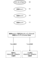
- FIG. 13 is a diagram showing an example of distinction between RACH procedures.
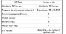
- FIG. 14 is a diagram showing an example of DCI format 1_0 (DCI field).
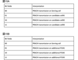
- 15A and 15B are diagrams showing associations between bit field values of DCI and corresponding interpretations according to the first embodiment.
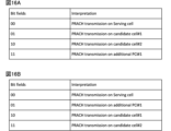
- FIG. 16A and 16B are diagrams showing associations between bit field values of DCI and corresponding interpretations according to the first embodiment.
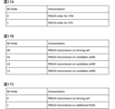
- 17A to 17C are diagrams showing associations between bit field values of DCI and corresponding interpretations according to the first embodiment.
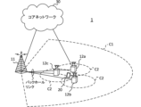
- FIG. 18 is a diagram illustrating an example of a schematic configuration of a wireless communication system according to an embodiment.
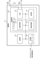
- FIG. 19 is a diagram illustrating an example of the configuration of a base station according to an embodiment.
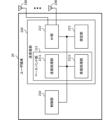
- FIG. 20 is a diagram illustrating an example of the configuration of a user terminal according to an embodiment.
- FIG. 21 is a diagram illustrating an example of the hardware configuration of a base station and a user terminal according to an embodiment.
- FIG. 22 is a diagram illustrating an example of a vehicle according to an embodiment.
- TCI transmission configuration indication state
- the TCI state may represent that which applies to the downlink signal/channel.
- the equivalent of the TCI state which applies to the uplink signal/channel may be expressed as a spatial relation.
- TCI state is information about the Quasi-Co-Location (QCL) of signals/channels and may also be called spatial reception parameters, spatial relation information, etc. TCI state may be set in the UE on a per channel or per signal basis.
- QCL Quasi-Co-Location
- QCL is an index that indicates the statistical properties of a signal/channel. For example, if a signal/channel has a QCL relationship with another signal/channel, it may mean that it can be assumed that at least one of the Doppler shift, Doppler spread, average delay, delay spread, and spatial parameters (e.g., spatial Rx parameters) is identical between these different signals/channels (i.e., it is QCL with respect to at least one of these).
- spatial parameters e.g., spatial Rx parameters
- the spatial reception parameters may correspond to a reception beam (e.g., a reception analog beam) of the UE, and the beam may be identified based on a spatial QCL.
- the QCL (or at least one element of the QCL) in this disclosure may be interpreted as sQCL (spatial QCL).
- QCL types QCL types
- QCL types A to D QCL types A to D
- the parameters (which may be called QCL parameters) are as follows: QCL Type A (QCL-A): Doppler shift, Doppler spread, mean delay and delay spread, QCL type B (QCL-B): Doppler shift and Doppler spread, QCL type C (QCL-C): Doppler shift and mean delay; QCL Type D (QCL-D): Spatial reception parameters.
- QCL Type A QCL-A
- QCL-B Doppler shift and Doppler spread
- QCL type C QCL type C
- QCL Type D QCL Type D
- the UE's assumption that a Control Resource Set (CORESET), channel or reference signal is in a particular QCL (e.g., QCL type D) relationship with another CORESET, channel or reference signal may be referred to as a QCL assumption.
- CORESET Control Resource Set
- QCL QCL type D
- the UE may determine at least one of a transmit beam (Tx beam) and a receive beam (Rx beam) for a signal/channel based on the TCI condition or QCL assumption of the signal/channel.
- Tx beam transmit beam
- Rx beam receive beam
- the TCI state may be, for example, information regarding the QCL between the target channel (in other words, the Reference Signal (RS) for that channel) and another signal (e.g., another RS).
- the TCI state may be set (indicated) by higher layer signaling, physical layer signaling, or a combination of these.
- target channel/RS target channel/reference signal
- reference RS reference signal
- the channel for which the TCI state or spatial relationship is set (specified) may be, for example, at least one of the following: a downlink shared channel (Physical Downlink Shared Channel (PDSCH)), a downlink control channel (Physical Downlink Control Channel (PDCCH)), an uplink shared channel (Physical Uplink Shared Channel (PUSCH)), and an uplink control channel (Physical Uplink Control Channel (PUCCH)).
- PDSCH Physical Downlink Shared Channel
- PDCCH Physical Downlink Control Channel
- PUSCH Physical Uplink Shared Channel
- PUCCH Physical Uplink Control Channel
- the RS that has a QCL relationship with the channel may be, for example, at least one of a synchronization signal block (SSB), a channel state information reference signal (CSI-RS), a sounding reference signal (SRS), a tracking CSI-RS (also called a tracking reference signal (TRS)), a QCL detection reference signal (also called a QRS), a demodulation reference signal (DMRS), etc.
- SSB synchronization signal block
- CSI-RS channel state information reference signal
- SRS sounding reference signal
- TRS tracking reference signal
- QRS QCL detection reference signal
- DMRS demodulation reference signal
- An SSB is a signal block that includes at least one of a Primary Synchronization Signal (PSS), a Secondary Synchronization Signal (SSS), and a Physical Broadcast Channel (PBCH).
- PSS Primary Synchronization Signal
- SSS Secondary Synchronization Signal
- PBCH Physical Broadcast Channel
- An SSB may also be referred to as an SS/PBCH block.
- An RS of QCL type X in a TCI state may refer to an RS that has a QCL type X relationship with a certain channel/signal (DMRS), and this RS may be called a QCL source of QCL type X in that TCI state.
- DMRS channel/signal
- the serving cell may be read as a TRP in the serving cell.
- Layer 1/layer 2 (L1/L2) and DCI/Medium Access Control Control Element (MAC CE) may be read as each other.
- MAC CE DCI/Medium Access Control Control Element
- a PCI different from the physical cell identity (PCI) of the current serving cell may be simply described as a "different PCI".
- a non-serving cell, a cell having a different PCI, and an additional cell may be read as each other.
- Scenario 1 corresponds to, for example, multi-TRP inter-cell mobility, but it may also be a scenario that does not correspond to multi-TRP inter-cell mobility.
- the UE receives from the serving cell the configuration necessary to use radio resources for data transmission and reception, including an SSB configuration for beam measurement of a TRP corresponding to a PCI different from that of the serving cell, and resources of the different PCI.
- the UE performs beam measurements of TRPs corresponding to different PCIs and reports the beam measurement results to the serving cell.
- the Transmission Configuration Indication (TCI) states associated with the TRPs corresponding to different PCIs are activated by L1/L2 signaling from the serving cell.
- the UE transmits and receives using UE-dedicated channels on TRPs corresponding to different PCIs.
- the UE must always cover the serving cell, including in the case of multi-TRP.
- the UE must use common channels (Broadcast Control Channel (BCCH), Paging Channel (PCH)) from the serving cell, as in the conventional system.
- BCCH Broadcast Control Channel
- PCH Paging Channel
- scenario 1 when the UE transmits and receives signals to and from an additional cell/TRP (a TRP corresponding to the PCI of the additional cell), the serving cell (the serving cell assumption in the UE) is not changed.
- the UE is configured with higher layer parameters related to the PCI of the non-serving cell from the serving cell. Scenario 1 may be applied, for example, in Rel. 17.
- Figure 1A shows an example of UE movement in Rel. 17. Assume that the UE moves from a cell (serving cell) with PCI #1 to a cell (additional cell) with PCI #3 (which overlaps with the serving cell). In this case, Rel. 17 does not support switching of the serving cell via L1/L2.
- An additional cell is a cell that has an additional PCI that is different from the PCI of the serving cell.
- the UE can receive/transmit UE-specific channels from the additional cell.
- the UE needs to be within the coverage of the serving cell to receive UE common channels (e.g., system information/paging/short messages). If the UE moves out of the coverage of the serving cell, a cell switch is required, such as by handover (also called L3 mobility).
- ⁇ Scenario 2> L1/L2 inter-cell mobility is applied.
- the serving cell can be changed using a function such as beam control without RRC reconfiguration.
- a function such as beam control without RRC reconfiguration.
- transmission and reception with an additional cell is possible without handover. Since handover requires RRC reconnection and creates a period when data communication is not possible, by applying L1/L2 inter-cell mobility that does not require handover, data communication can be continued even when the serving cell is changed.
- Scenario 2 may be applied in, for example, Rel. 18. In scenario 2, for example, the following procedure is performed.
- the UE receives SSB configuration of a cell (additional cell) with a different PCI from the serving cell for beam measurement/serving cell change.
- the UE performs beam measurements of cells using different PCIs and reports the measurement results to the serving cell.
- the UE may receive a configuration of a cell having a different PCI (serving cell configuration) by higher layer signaling (e.g., RRC). That is, a pre-configuration regarding a serving cell change may be performed. This configuration may be performed together with the configuration in (1) or separately.
- the TCI states of cells with different PCIs may be activated by L1/L2 signaling according to the change of serving cell. The activation of the TCI state and the change of serving cell may be performed separately.
- the UE changes the serving cell (assumed serving cell) and starts receiving/transmitting using the pre-configured UE-specific channel and TCI state.
- scenario 2 the serving cell (the assumed serving cell in the UE) is updated by L1/L2 signaling.
- Scenario 2 may be applied in Rel. 18.
- Figure 1B shows an example of UE movement in Rel. 18.
- the serving cell is switched by L1/L2 (e.g., DCI/MAC CE).
- the UE can receive/transmit UE-dedicated/common channels to/from the new serving cell (or target serving cell).
- the UE may move out of the coverage of the current serving cell (e.g., Current serving cell).
- Fig. 2 is a diagram showing an example of an LTM procedure. Note that L1/L2 inter-cell mobility and L1L2-triggered mobility (LTM) may be read as interchangeable terms. Note that the procedure in Fig. 2 may correspond to the above-mentioned scenario 2. Each procedure in Fig. 2 will be described below.
- the UE establishes an RRC connection to the current serving cell (PCI #1) and sends an L3 measurement report.
- the serving cell base station
- the UE and serving cell perform RRC reconfiguration.
- the candidate cell may include the target cell (PCI #3).
- the UE, serving cell, target cell, and candidate cell perform DL synchronization.
- the UE performs and reports L1 (e.g., L1-RSRP/SINR) measurements of the serving cell/candidate cell/target cell.
- L1 e.g., L1-RSRP/SINR
- the UE, serving cell, target cell, and candidate cell perform UL synchronization.
- the serving cell decides to switch the serving cell to the target cell (PCI #3) based on the L1 measurement report and sends a cell switch command to the UE. After receiving the cell switch command, the UE starts PDCCH monitoring for the target cell.
- the UE performs a RACH procedure to the target cell.
- the UE transmits an RRC reconfiguration complete message and also transmits the first data to the target cell. This first data transmission is based on a dynamic grant or a configuration grant related to the beam of the target cell.
- the target cell transmits an ACK for this transmission to the UE.
- the UE can reduce the time without data transmission (interruption time) in Rel. 18 L1/L2 inter-cell mobility (e.g., above scenario 2).
- the time without data transmission can be reduced compared to the method of handing over based on L3 measurement results (L3 handover).
- Figure 3 shows an example of a comparison between L3 handover and LTM in Rel. 18.
- the UE first performs L3 measurements and decides to perform handover based on the measurement results. Then, the UE and the current serving cell perform RRC reconfiguration. The UE then performs DL synchronization and UL synchronization with the target serving cell. The UE performs L1 measurements/reports for the target serving cell, and after receiving a beam instruction, transmits the first UL data to the target serving cell. In this case, the UE does not transmit UL data during the period from the handover decision to the first UL data transmission (interruption time).
- the UE In the case of LTM in Rel. 18, the UE first performs L3 measurements. Then, the UE, current serving cell, and target serving cell perform RRC reconfiguration. Then, the UE performs DL synchronization with the target serving cell. Then, the UE performs L1 measurements/reports to the current serving cell and target serving cell, and performs UL synchronization. Then, the current serving cell sends a cell switch command (including beam instruction) by L1/L2 (DCI/MAC CE) to the UE. Then, the UE transmits the first UL data to the target serving cell. In this case, the period from receiving the cell switch command to transmitting the first UL data is the interruption time of UL transmission, but the interruption time is shorter than in the case of L3 handover.
- FIG. 4 is a diagram showing an example of the association between a serving cell and a candidate cell.
- SpCell#0, SCell#1, or SCell#2 is assumed to be a serving cell.
- SpCell means a special cell (including a primary cell (PCell) and a primary secondary cell (PSCell)).
- SCell means a secondary cell.
- SpCell#0 is associated with candidate cell#0-1, candidate cell#0-2, and candidate cell#0-3.
- SCell#1 is associated with candidate cell#1-1.
- SCell#2 is associated with candidate cell#2-1, 2-2. In this way, one or more candidate cells (candidate serving cells) may be associated with a serving cell.
- the following options 1 and 2 can be considered for setting candidate cells (candidate cells).
- the information in the serving cell configuration may include information about multiple candidate cells, in which case the multiple candidate cells need to share the same PDCCH/PDSCH/UL etc. configurations as the serving cell.
- mimoParam-r17 is added under the serving cell configuration (ServingCellConfig), and PCI setting information is added.
- mimoParam-r17 may include additionalPCI-ToAddModList-r17, which is an information list of additional SSBs with PCIs different from the PCI of the serving cell.
- additionalPCI-ToAddModList-r17 is an information list of additional SSBs with PCIs different from the PCI of the serving cell.
- the same settings as the serving cell may be applied to candidate cells (additional cells, cells with additionalPCI), with the exception of some information.
- Multiple candidate cells may be associated with each serving cell by reusing the carrier aggregation (CA) configuration framework, with a complete configuration (e.g., ServingCellConfig) corresponding to each cell. That is, the candidate cells may not share configuration information with the serving cell and may have a separate configuration. The UE is provided with the complete configuration of each candidate cell, so that it can communicate properly with the candidate cells.
- CA carrier aggregation
- an SpCell can be configured for each cell group and multiple SCells can be added.
- a serving cell can be configured for each cell group for L1/L2 inter-cell mobility, and multiple candidate cells can be configured.
- the candidate cells can be activated/deactivated by the MAC CE.
- the candidate cells can be activated/deactivated by activating/deactivating the TCI information corresponding to the candidate cells by the MAC CE. This method is considered to be beneficial for reducing the complexity of UE operations.
- FIG. 5A is a diagram showing a first example of option 2 for candidate cell configuration.
- a common candidate cell pool for cell switching in the MCG/SCG is applied to the candidate cells.
- the candidate cells are treated as one pool (group) regardless of the frequency band.
- Figure 5B is a diagram showing a second example of option 2 for candidate cell configuration.
- multiple cell groups are configured, and cell group switching is possible by L1/L2 signaling.
- Candidate cells are configured for each cell group, and the configuration for each group includes the indices of the corresponding SpCell and SCell.
- Implicit or explicit signaling for serving cell change indication is described.
- a particular Control Resource Set (e.g., at least one of CORESET#0, CORESET of CH5 Type0-CSS, CORESET of CH6/CH7/CH8 CSS) is indicated (activated) by a MAC CE together with one or more TCI states associated with a cell of a PCI different from that of the serving cell (when, for a particular CORESET, one or more TCI states associated with a cell of a PCI different from that of the serving cell are indicated/activated by a MAC CE), the UE may determine to change the serving cell to another cell (cell x, a cell with a different PCI). That is, this activation may implicitly indicate changing the serving cell to another cell.
- CORESET Control Resource Set
- the UE may update beams of other CORESET IDs, other CORESETs using CH6/CH7/CH8, or other CORESETs using CSS to the same TCI state as the activated TCI state.
- the UE may determine to change the serving cell to another cell (cell x), i.e., the association may implicitly indicate the change of the serving cell to another cell.
- the NW base station
- the MAC CE activates the TCI state of a PDSCH associated with a cell with a different PCI, it must also include the TCI state related to another cell (e.g., the current serving cell or a cell with a second different PCI).
- the UE may determine to change the serving cell to another cell (cell x), i.e., the association may implicitly indicate the serving cell change to another cell.
- Option 2-1 An example of a serving cell change instruction will be described below. Note that activation/deactivation of a non-serving cell, change of a serving cell, and transmission/reception with another cell (non-serving cell) having a physical cell ID different from the physical cell ID of the serving cell may be interpreted as being interchangeable.
- the UE may receive a new MAC CE including at least one of the fields (information) indicating the following (1) to (3) corresponding to the non-serving cell, which is used for activating/deactivating the non-serving cell.
- the UE may decide to change the serving cell to another cell (non-serving cell).
- the UE may also control transmission and reception of DL signals/UL signals with the non-serving cell based on the information.
- the non-serving cell may be one or multiple. In the example shown below, a MAC CE including multiple fields indicating multiple non-serving cell indexes is applied.
- Non-serving cell ID used for activation The non-serving cell ID may be replaced with any information corresponding to a non-serving cell (capable of identifying a non-serving cell).
- any of (3-1) to (3-5) may be applied.
- (3-1) PCI PCI used directly). For example, 10 bits are used.
- CSI resource configuration ID (CSI-ResourceConfigId) (when CSI-ResourceConfigId corresponds to one or more non-serving cells).
- CSI-ResourceConfigId (when CSI-ResourceConfigId corresponds to one or more non-serving cells).
- 3-5 A bitmap indicating the activation/deactivation of each non-serving cell.
- the size (number of bits) of the bitmap may be the same as the number of non-serving cells configured on this CC. For example, when activating the second non-serving cell among three non-serving cells, "010" is set.
- At least one of the pieces of information included in the MAC CE may be included in the DCI. Or, at least one of the serving cells activated by the MAC CE may be indicated by the DCI.
- the MAC CE/DCI may include a field indicating the TCI status/SSB/CSI-RS from a cell with a different PCI so that the UE can recognize the DL beam to be monitored on the target cell (the serving cell after the change).
- the UE may create and transmit a beam report (CSI report) using the TCI status/SSB/CSI-RS.
- the UE may receive a MAC CE in which a new 1-bit field "C" is added to the existing MAC CE.
- the field indicates whether to change the serving cell.
- the UE may receive the MAC CE and determine whether to change the serving cell to another cell based on the field.
- a field indicating the serving cell index/PCI/other ID (such as the new ID in Option 2-1 described above) and a field indicating the TCI state/SSB/CSI-RS of the target cell (the serving cell after the change) may be included in the MAC CE.
- the UE can appropriately change the serving cell.
- [Serving Cell Switch Example 1] 6 is a diagram showing a serving cell switch example 1.
- the serving cell SpCell#0 of the MCG/SCG when the serving cell is instructed to be changed to the candidate cell #0-2 by L1/L2 signaling, the candidate cell #0-2 becomes the new serving cell SpCell#0.
- the serving cell SCell#2 of the MCG/SCG when the serving cell is instructed to be changed to the candidate cell #2-1 by L1/L2 signaling, the candidate cell #2-1 becomes the new serving cell SCell#2.
- the RRC/MAC CE may configure a global candidate cell ID (cell #3,...,8) for each cell group, band, FR, and UE.
- the UE may be instructed to switch the serving cell by the global candidate cell ID.
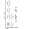
- Figure 7 shows a serving cell switch example 2. Similar to Figure 5A, a pool of multiple candidate cells can be configured, and the serving cell can be switched to any (activated) candidate cell in the pool by L1/L2 signaling.
- the configured candidate cell can be either an SpCell or an SCell based on L1/L2 signaling.
- the UE may receive an instruction to change the serving cell (from cell #2-1 to candidate cell #4) via MAC CE/DCI.
- the indicated candidate cell #4 then becomes the SpCell of the new cell group (MCG/SCG).
- the RRC/MAC CE may configure a cell group, and the UE may perform a serving cell switch based on the cell group switch.
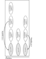
- Figure 8 shows serving cell switch example 3.
- the UE receives an instruction to change the cell group having the serving cell (change to candidate cell group #1) via MAC CE/DCI.
- the cells included in the indicated candidate cell group #1 become the new serving cells (SpCell, SCell).
- candidate cells #0, #1, and #2 included in the indicated candidate cell group #1 become new SpCell #0, SCell #1, and SCell #2.
- the serving cell group is switched.
- LTM L1L2-triggered mobility
- LTM L1L2-triggered mobility
- FIG 9 shows an overview of L1L2-triggered mobility (LTM).
- LTM and L1/L2 inter-cell mobility may be interpreted as interchangeable.
- the UE receives candidate cell configurations from the NW during UE reconfiguration.
- the UE reconfiguration includes T RRC , T proccesing1/T proccesing2 .
- T RRC e.g., up to 10 ms
- T proccesing1/T proccesing2 e.g., up to 20 ms for same FR and up to 40 ms for different FR
- This may include L2/3 reconfiguration, RF retuning, baseband retuning, security update if necessary, etc.
- T search (e.g. 0 ms if cell is known, max 60 ms if cell is unknown) is the time required to search for the target cell.
- T ⁇ is the time for fine tracking and acquisition of all timing information.
- T margin (e.g. max 2 ms) is the time for post processing of SSB and CSI-RS.
- the L1 measurement includes T meas (SMTC period (eg, 20 ms)), which is the measured delay from the appearance of the target to the cell switch command.
- T meas SMTC period (eg, 20 ms)
- T IU e.g., max. 15 ms
- T RAR e.g., max. 4 ms
- T cmd e.g., max. 5 ms
- L1/L2 commands HARQ and paging
- T first-data after T cmd is the time when the UE makes the first DL reception/UL transmission on the indicated beam of the target cell after the RAR.
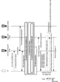
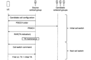
- FIG. 10 is a diagram showing an example of a PDCCH ordered RACH with RAR monitoring.
- the source cell and the source cell group may be interchangeable.
- the candidate cell and the candidate cell group may be interchangeable.
- the source cell may transmit information regarding the configuration of the candidate cell (e.g., candidate cell configuration information) to the UE.
- the source cell may also transmit a PDCCH order (e.g., DCI format 1_0) used to trigger the PRACH to the UE.
- the PDCCH order (or DCI) may indicate the candidate cell (e.g., one candidate cell)/random access occasion (RO) that is the target of the PRACH trigger/transmission.
- the UE transmits the PRACH in the RACH procedure to the candidate cell based on the PDCCH order to acquire the TAG/TA.
- the source cell then transmits a response signal (RAR) to the PRACH to the UE.
- the RAR may include information about the TA (e.g., TA indication).
- the RAR e.g., PDSCH including the RAR/PDCCH that schedules the PDSCH
- the RAR may be monitored in a specific search space (e.g., common search space (CSS)) of a specific cell (e.g., SpCell) among the current serving cells (only within a Distributed Unit (DU)).
- TA adjustment e.g., TA maintenance
- TA maintenance is performed in the source cell.
- the source cell may then send a cell switch command to the UE.
- TA information may be moved/notified from the source cell to the target cell.
- the UE may control UL transmission based on the acquired TA. For example, after the initial cell switch, the UE may perform the first UL transmission using the initial TA if UL synchronization of all candidate cells has not been completed.
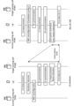
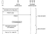
- Figure 11 is a diagram showing an example of a RACH (PDCCH ordered RACH) with a PDCCH order that does not have RAR monitoring. Only the differences between Figure 11 and Figure 10 will be explained.
- the PDCCH order used to trigger the PRACH may indicate one or more candidate cells (e.g., multiple candidate cells)/random access occasions to be the target of the PRACH trigger/transmission.
- the UE may transmit a PRACH in the RACH procedure to the candidate cells based on the PDCCH order to acquire multiple TAGs/TAs.
- the source cell does not transmit a PRACH response signal (e.g., RAR).
- the source cell may indicate information regarding the TA (e.g., TA indication) to the UE using a cell switch command.
- a RACH without RAR and a RACH without RAR monitoring may be interpreted as mutually interchangeable.
- a RACH may be interpreted as a PRACH transmission triggered by a PDCCH order.
- a RACH procedure/PRACH transmission without RAR monitoring may be interpreted as a RACH procedure/PRACH transmission in which RAR monitoring is not required, or a RACH procedure/PRACH transmission in which RAR monitoring is not required.
- DCI format 1_0 includes a DCI format identifier field, a bit field that is always set to 1, and a frequency domain resource assignment field. If the cyclic redundancy check (CRC) of DCI format 1_0 is scrambled by the C-RNTI and the frequency domain resource assignment field is all 1, then the DCI format 1_0 is for a random access procedure initiated by a PDCCH order, and the remaining fields are a random access preamble, a UL/supplementary uplink (SUL) indicator, a SS/PBCH index (SSB index), a PRACH mask index, and reserved bits (12 bits).
- CRC cyclic redundancy check
- the PRACH mask index field indicates the PRACH occasion of the PRACH transmission that is associated with the SS/PBCH block index indicated by the SS/PBCH block index field of the PDCCH order if the value of the random access preamble index field is not zero.
- FIG. 12 shows DCI format 1_0 that is CRC scrambled by the C-RNTI.
- the frequency domain resource assignment may be used, for example, for a PDCCH order (RACH) according to an instruction from a PDCCH. For example, when the frequency domain resource assignment indicates all 1s, this may mean that the DCI format 1_0 is used as a PDCCH order.
- the random access preamble index may be used for Contention based Random Access (CBRA). For example, when the random access preamble index is all 0, it may mean that it is used for CBRA.
- the reserved bits are 12 bits when operating in a cell with spectrum shared channel access, and 10 bits otherwise.
- TA acquisition of the candidate cell may be supported before the cell switch command.
- at least RACH of PDCCH order may be supported.
- the PDCCH order may be triggered only by the source cell (e.g., serving cell).
- the candidate cell/candidate cell RACH occasion (RO) may be indicated by DCI transmitted in the PDCCH order.
- the configuration of the RACH resource of the candidate cell may be provided to the UE before the PDCCH order.
- At least one of a method with RAR monitoring and a method without RAR monitoring may be applied.
- information regarding the timing advance of the candidate cell e.g., TA information/TAC
- information regarding the timing advance of the candidate cell e.g., TA information/TAC
- TA information/TAC information regarding the timing advance of the candidate cell
- the UE receives the SS/PBCH block (SSB), transmits Msg. 1 (PRACH/random access preamble/preamble), receives Msg. 2 (PDCCH, PDSCH including random access response (RAR)), transmits Msg. 3 (PUSCH scheduled by RAR UL grant), and receives Msg. 4 (PDCCH, PDSCH including UE contention resolution identity).
- Msg. 1 PRACH/random access preamble/preamble
- RAR random access response
- Msg. 3 PUSCH scheduled by RAR UL grant
- Msg. 4 PDCCH, PDSCH including UE contention resolution identity
- SSB reception includes PSS detection, SSS detection, PBCH-DMRS detection, and PBCH reception.
- PSS detection includes detection of part of the physical cell ID (PCI), detection (synchronization) of the OFDM symbol timing, and (coarse) frequency synchronization.
- SSS detection includes detection of the physical cell ID.
- PBCH-DMRS detection includes detection of (part of) the SSB index within a half radio frame (5 ms).
- PBCH reception includes detection of the system frame number (SFN) and radio frame timing (SSB index), reception of configuration information for remaining minimum system information (RMSI, SIB1) reception, and recognition of whether the UE can camp on that cell (carrier).
- SFN system frame number
- SSB index radio frame timing
- SSB has a bandwidth of 20RB and a time of 4 symbols.
- the transmission period of SSB can be set from ⁇ 5, 10, 20, 40, 80, 160 ⁇ ms.
- multiple symbol positions of SSB are specified based on the frequency range (FR1, FR2).
- the PBCH has a payload of 56 bits. N repetitions of the PBCH are transmitted within a period of 80 ms, where N depends on the SSB transmission period.
- the system information consists of the MIB, RMSI (SIB1), and other system information (OSI) carried by the PBCH.
- SIB1 contains information for RACH configuration and RACH procedures.
- the time/frequency resource relationship between the SSB and the PDCCH monitoring resources for SIB1 is set by the PBCH.
- a base station using beam correspondence transmits multiple SSBs using multiple beams for each SSB transmission period.
- the multiple SSBs each have multiple SSB indices.
- a UE that detects an SSB transmits a PRACH in the RACH occasion associated with that SSB index and receives an RAR in the RAR window.
- RACH procedure triggered by PDCCH order In an existing system (e.g., before Rel. 17), for a RACH procedure for a specific cell (e.g., SpCell), the UE performs the RACH procedure assuming that the PDCCH order and the PDCCH for RAR have the same QCL characteristics for the RACH of the PDCCH order.
- the PDCCH for RAR may be a PDCCH transmitted by the base station in response to a PRACH triggered to the UE by the PDCCH order (or transmitted from the UE).
- the RAR may be included in the PDSCH scheduled by the PDCCH for the RAR.
- the QCL characteristics may be read as DMRS QCL characteristics.
- the UE may assume that the PDCCH containing DCI format 1_0 and the PDCCH order have the same DMRS antenna port quasi-co-location characteristics.
- the specific CORESET may be a CORESET associated with a Type 1 CSS set (e.g., Type 1-PDCCH CSS set).
- the UE may assume the DMRS antenna port quasi-co-location property of the CORESET associated with the Type 1-PDCCH CSS set for reception of the PDCCH containing DCI format 1_0.
- a RACH may be triggered for each TRP (or for each serving cell/non-serving cell).
- a PDCCH order that triggers the RACH procedure for a TRP or a serving cell/non-serving cell
- the PDCCH order and the PDCCH for RAR are transmitted from different TRPs. In such a case, it is necessary to relax/change the restriction that the PDCCH order and the PDCCH for RAR have the same DMRS QCL characteristics.
- a PDCCH order from TRP#1 triggers a RACH to TRP#2, and an RAR is transmitted from TRP#2.
- an RAR is transmitted from TRP#2.
- a PDCCH order from TRP#2 triggers a RACH to TRP#2 and an RAR is sent from TRP#1.
- This example may occur in inter-cell multi-TRP (e.g., inter-cell M-TRP) cases when the UE cannot receive a Type 1 CSS set from the TRP of a non-serving cell.
- the random access procedure is initiated by a PDCCH order, by the MAC entity itself, or by the RRC for specification compliant events. Within a MAC entity, there can only be one random access procedure in progress at any given time.
- the random access procedure for an SCell is only initiated by a PDCCH order with a ra-PreambleIndex different from 0b000000.
- the MAC entity When a random access procedure is initiated on the serving cell, the MAC entity does the following: - If the random access procedure is initiated by a PDCCH order and the ra-PreambleIndex explicitly provided by the PDCCH is not 0b000000, or if the random access procedure is initiated for a reconfiguration with synchronization and a 4-step RA type contention-free random access resource is explicitly provided by rach-ConfigDedicated for the BWP selected for the random access procedure, set RA_TYPE to 4-stepRA.
- the MAC entity shall do the following: - If ra-PreambleIndex is explicitly provided by the PDCCH and ra-PreambleIndex is not 0b000000, set PREAMBLE_INDEX to the reported ra-PreambleIndex and select the SSB reported by the PDCCH. - If an SSB is selected as above, determine the next available PRACH occasion from the PRACH occasions allowed by the restrictions given by ra-ssb-OccasionMaskIndex and corresponding to the selected SSB (the MAC entity selects a PRACH occasion randomly with equal probability from among consecutive PRACH occasions corresponding to the selected SSB according to the specifications. The MAC entity may take into account the possibility of occurrence of measurement gaps when determining the next available PRACH occasion corresponding to the selected SSB).
- a new random access procedure is initiated while another random access procedure is already in progress within a MAC entity, it is up to the UE implementation to continue the ongoing procedure or initiate a new procedure (e.g. SI request).
- a new procedure e.g. SI request
- this procedure shall be considered as the same random access procedure as the ongoing one and shall not be reinitialized.
- the UE may determine/judge the RACH means (type) to be applied based on the information (higher layer signaling (e.g., RRC/MAC CE)/physical layer signaling (DCI)) shown in the following aspects 1-1 to 1-2.
- higher layer signaling e.g., RRC/MAC CE
- DCI physical layer signaling
- the (current) serving cell may be configured as a candidate cell, for which it is assumed that the PDCCH order RACH without RAR is not used (applied).
- Whether to apply a PDCCH order RACH without RAR to a candidate cell may be predefined by a specification or may be determined based on UE capabilities. Alternatively, whether to apply a PDCCH order RACH without RAR to a candidate cell may be set/indicated by higher layer signaling/physical layer signaling.
- an existing PDCCH order RACH e.g., a PDCCH with an RAR
- a PDCCH order RACH without an RAR may be set/indicated by higher layer signaling/physical layer signaling.
- Any of the above PDCCH orders RACH may be set/indicated for each cell/CC, or may be set/indicated for all serving cells.
- the PDCCH order RACH without RAR may be used/applied when a power ramping counter for LTM is set for a serving cell set as a candidate cell.
- the power ramping counter may be set for each candidate cell (it may be assumed/presumed that it is set).
- the UE may determine/judge the type of PDCCH order RACH (the RACH procedure to be applied) based on the PDCCH order.
- a bit in the DCI may be used to indicate whether to perform a legacy PDCCH order RACH, a PDCCH order RACH without an RAR, or whether the PDCCH order is an indication for an LTM or non-LTM case.
- a new bit field or an existing reserved bit field may be used for that one bit.
- the one bit may specifically indicate a PDCCH order RACH that does not have an RAR (a PDCCH order RACH for LTM) with "0" and an existing PDCCH order RACH with "1".
- RAR a PDCCH order RACH for LTM
- RACH existing PDCCH order
- the implicit instruction may apply one of the following options 1-2.
- the type of PDCCH order RACH may be indicated by the candidate cell index. For example, when a specific candidate cell index is indicated, it may be indicated that a PDCCH order RACH without RAR is applied.
- a candidate cell index is also assigned to the serving cell that is set as a candidate cell.
- the field indicating the candidate cell index in the PDCCH order includes both an index for the serving cell and an index for the candidate cell.
- FIG. 13 is a diagram showing an example of distinction of the RACH procedure according to the first embodiment. As shown in FIG. 12, for example, the following cells may be indicated using a 2-bit field: Serving cell: 00, Candidate cell #1: 01, Candidate cell #2: 10, Candidate cell #3: 11.
- the candidate cell index of the serving cell set as a candidate cell is #2.
- this may mean/indicate (may be interpreted as meaning that the existing PDCCH order RACH is applied/used).
- this may mean/indicate (may be interpreted as meaning that the PDCCH order RACH without RAR is applied/used.
- the type of PDCCH order RACH may be indicated (distinguished) based on whether the candidate cell index of the serving cell set as the candidate cell and the candidate index indicated by the PDCCH order (DCI) are the same or different (serving cell).
- the PDCCH order RACH for LTM may be indicated.
- the candidate cell index of the serving cell set as the candidate cell is different from the candidate index indicated by the PDCCH order (DCI) (if the indication by the PDCCH order is the serving cell), the existing PDCCH order RACH may be indicated.
- a certain bit (X bits) of the new bit field for LTM is all 0, it may be instructed to apply the existing PDCCH order RACH. Otherwise (if the X bits of the new bit field for LTM are not all 0), it may be instructed to apply the PDCCH order RACH without RAR.
- the above-mentioned specific bits may indicate the candidate cell index and whether the PRACH is a first transmission or a retransmission.
- the UE may control the power ramping depending on the type of PDCCH order RACH as follows:
- the UE may perform power ramping using a counter for LTM (power ramping counter) set for each candidate cell or for all candidate cells.
- LTM power ramping counter
- the UE may perform power ramping using a counter (power ramping counter) of the serving cell (configured for the serving cell) in the same manner as in the existing operation.
- the UE can appropriately determine/judge the RACH to be applied depending on the configured candidate cells.
- FIG. 14 is a diagram showing an example of DCI format 1_0 (DCI field). Regarding FIG. 14, the description of the parts common to the already-mentioned FIG. 12 will be omitted, and only the differences will be described. As shown in FIG. 14, DCI format 1_0 (PDCCH order) may include a cell indicator field. The number of bits of the cell indicator field may depend on the number of candidate cells.
- ceil(X) may mean multiplying X by a ceiling function.
- the number of candidate cells used to calculate the bit size is the number of candidate cells C+1 (+1 corresponds to the serving cell) that have RACH configuration provided for early TA acquisition.
- a PDCCH order RACH without an RAR is triggered by the cell indicator field of the PDCCH order indicating the candidate cell.
- an existing PDCCH order RACH (i.e., with RAR) is triggered by the cell indicator field of the PDCCH order indicating a specific value of the serving cell (e.g., all zeros).
- the current specifications do not provide clear provisions for distinguishing from existing operations. Furthermore, it is not clear which operation (i.e., with RAR/without RAR) is applied to obtain the TA of a candidate cell configured as the current serving cell (e.g., the current SCell).
- Alt1 to Alt2 as a method for indicating which RACH operation to apply.
- the UE may always use the existing PDCCH order RACH.
- EarlyULSyncConfig may be not be set for the candidate cell that is set as the current serving cell.
- the cell indicator field of the PDCCH order may always indicate all 0s for the serving cell.
- the UE may utilize both the existing PDCCH order RACH and the PDCCH order RACH without the RAR.
- One method of indication is to indicate by the cell indicator field of the PDCCH order. For example, if all values are 0, an existing PDCCH order RACH is indicated, and if it is the value of the candidate cell index, a PDCCH order RACH without an RAR may be indicated.
- the operation for distinguishing between the existing RACH operation and the RACH operation without RAR may be newly defined by the specification.
- the UE operation upon receiving the RAR may be defined by the specification.
- the cell indicator (field) indicates the cell for the corresponding PRACH transmission with ceil(log 2 (C+1)) bits if the UE is configured with the higher layer parameter EarlyUlSyncConfig.
- C is the number of candidate cells set by the upper layer parameter EarlyUlSyncConfig.
- this field indicates the serving cell, otherwise it is a 0 bit.
- the MAC entity performs certain actions regarding the reception of the random access response, regardless of the occurrence of a measurement gap.
- except when the serving cell is indicated as an LTM candidate cell by a PDCCH order may be read as "except when the RACH procedure is triggered by a PDCCH order indicating an LTM candidate cell index" and "except when the RACH procedure is triggered by a PDCCH order indicating a non-zero cell indicator.”
- a PDCCH order RACH without RAR may be applied.
- the UE can appropriately determine/judge the RACH to be applied depending on the configured candidate cells.
- the higher layer signaling may be, for example, any one of Radio Resource Control (RRC) signaling, Medium Access Control (MAC) signaling, broadcast information, other messages (e.g., messages from the core network such as positioning protocols (e.g., NR Positioning Protocol A (NRPPa)/LTE Positioning Protocol (LPP)) messages), or a combination of these.
- RRC Radio Resource Control
- MAC Medium Access Control
- LPP LTE Positioning Protocol
- the physical layer signaling may be, for example, Downlink Control Information (DCI), Uplink Control Information (UCI), etc.
- DCI Downlink Control Information
- UCI Uplink Control Information
- cell, PCI, serving cell, SpCell, source serving cell, reference/reference cell, CC, BWP, BWP in CC, and band may be interchanged.
- additional cell, other cell, non-serving cell, cell with different PCI, candidate cell, candidate serving cell, cell with PCI different from the PCI of the current serving cell, another serving cell, target cell, target serving cell, and neighbor cell may be interchanged.
- switch, change, and update may be interchanged.
- Serving cell may be interchanged with the serving cell before the switch or the serving cell after the switch.
- LTM applied, cell applied, and cell switch may be interchanged.
- LTM applied, beam applied, and beam switch may be interchanged.
- RACH resource, RA resource, PRACH preamble, occasion, RACH occasion (RO), PRACH occasion, repetition resource, repetition setting resource, resources set for RO/repetition, time instance and frequency instance, time resource and frequency resource, RO/preamble resource, repetition, PRACH resource, time/frequency resource for PRACH, preamble setting/index, mask setting/index, PRACH setting may be read as interchangeable.
- RACH procedure
- PRACH transmission triggered by a PDCCH order and PDCCH order RACH
- RACH without RAR RACH without RAR monitoring
- PDCCH order RACH without RAR PDCCH order RACH for LTM
- RACH procedure/PRACH transmission without RAR monitoring may be read as RACH procedure/PRACH transmission in which RAR monitoring is not required, or RACH procedure/PRACH transmission in which RAR monitoring is not required.
- not having an RAR, not needing RAR monitoring, not applying an RAR, not needing an RAR, and being for LTM use may be interpreted interchangeably.
- having an RAR, needing RAR monitoring, applying an RAR, and requiring an RAR may be interpreted interchangeably.
- inter-cell mobility e.g., L1/L2 inter cell mobility
- L1/L2 inter-cell mobility may be interpreted as at least one of cell switching, cell switch, and cell change.
- the first embodiment describes the fields of the PDCCH order.
- a cell indicator indicating a candidate cell ID, a candidate configuration ID, etc. is included in a PDCCH order.
- a PRACH triggered by a PDCCH order is transmitted in a cell indicated by the cell indicator.
- the PRACH triggered by this PDCCH order is transmitted in the cell indicated by the additional active PCI.
- Opt1 In Opt1, an example will be described in which two (two types) of fields are used for LTM and 2TA. That is, one field may be defined for LTM and one field may be defined for 2TA.
- C is the number of candidate cells configured in the RACH configuration provided for early TA acquisition, i.e., it may be the number of candidate cells configured by the higher layer parameter EarlyUlSyncConfig.
- D may represent the number of additional active non-serving cell PCIs for 2TA, or the number of PCIs configured by RRC.
- bit field value is all zeros (e.g., "00"), it may mean that PRACH is being transmitted in the serving cell (or the PDCCH order is considered as an existing PDCCH order). Otherwise (e.g., [01]/[10]/[11]), it may indicate an additional active non-serving cell PCI.
- the bit size N of the above mentioned fields may be set/indicated by higher layer signaling/physical layer signaling.
- the order of the additional PCI/candidate cell IDs may be set/indicated by higher layer signaling/physical layer signaling or may be predefined by a specification.
- the order of the additional PCI/candidate cell IDs may be ascending or descending.
- FIGS. 15A and 15B are diagrams showing the association between the bit field values of the DCI for Opt1 of the first embodiment and the corresponding interpretations.
- bit field value when the bit field value is designated as "00", it may mean that the PRACH is transmitted in the serving cell.
- bit field value is designated as "01"/"10"/"11", it may mean that the PRACH is transmitted in the candidate cells #1/#2/#3.
- bit field value when the bit field value is designated as "00", it may mean that the PRACH is transmitted in the serving cell.
- bit field value is designated as "01"/"10"/"11", it may mean that the PRACH is transmitted in the additional PCI #1/#2/#3.
- Opt1 allows separate fields to indicate candidate cells for LTM and additional PCIs for 2TA.
- C may be the number of candidate cells configured in the RACH configuration provided for early TA acquisition, i.e., the number of candidate cells configured by the higher layer parameter EarlyUlSyncConfig.
- D may represent the number of additional active non-serving cell PCIs for 2TA, or the number of PCIs configured by RRC.
- bit field value is all zeros (e.g., "00"), it may mean that a PRACH is being transmitted in the serving cell (or the PDCCH order is considered an existing PDCCH order). Otherwise (e.g., [01]/[10]/[11]), it may indicate a candidate cell or an additional active PCI.
- the bit size N of the above mentioned fields may be set/indicated by higher layer signaling/physical layer signaling.
- the order of the additional PCI/candidate cell IDs may be set/indicated by higher layer signaling/physical layer signaling or may be predefined by a specification.
- the order of the additional PCI/candidate cell IDs may be ascending or descending.
- the two cell lists are separate for LTM and 2TA, which cell is indicated by the smaller/larger value may be set/indicated by higher layer signaling/physical layer signaling, or may be predefined by the specifications.
- values 1 (01) and 2 (10) may correspond to candidate cells for LTM, and a value of C+1 (11) may correspond to a non-serving cell for 2TA.
- a value of 1 (01) may correspond to a non-serving cell for 2TA, and values D+1 (10) and D+2 (11) may correspond to candidate cells for LTM.
- bit field value when the bit field value is designated as "00”, it may mean that the PRACH is transmitted in the serving cell.
- the bit field value is designated as "01"/"10", it may mean that the PRACH is transmitted in the candidate cell #1/#2 for LTM.
- the bit field value is designated as "11”, it may mean that the PRACH is transmitted in the additional PCI #1 for 2TA.
- Opt2 allows one joint field to indicate candidate cells for LTM and additional PCIs for 2TA.
- C may be the number of candidate cells configured in the RACH configuration provided for early TA acquisition, i.e., the number of candidate cells configured by the higher layer parameter EarlyUlSyncConfig.
- D may represent the number of additional active non-serving cell PCIs for 2TA, or the number of PCIs configured by RRC.
- bit field value is all zeros (e.g., "00"), this may mean that a PRACH is being transmitted in the serving cell (or the PDCCH order is considered as an existing PDCCH order).
- the bit size N of the above mentioned fields may be set/indicated by higher layer signaling/physical layer signaling.
- the additional field (function instruction field) may be assigned, for example, one bit. If the additional field indicates "0", it may mean that the common field is used for LTM. If the additional field indicates "1", it may mean that the common field is used for 2TA.
- the order of the additional PCI/candidate cell IDs may be set/indicated by higher layer signaling/physical layer signaling or may be predefined by a specification.
- the order of the additional PCI/candidate cell IDs may be ascending or descending.
- Opt1 the field corresponding to the function that is not configured
- Opt3 the additional field in Opt3
- FIGS. 17A to 17C are diagrams showing the association between the bit field values of the DCI related to Opt3 of the first embodiment and the corresponding interpretations.
- FIG. 17A is a diagram showing an example of an additional field.
- bit value of the additional field when the bit value of the additional field is designated as "0", it may mean that the common field is included in the PDCCH order for LTM (the common field indicates the direction of LTM).
- bit value of the additional field when the bit value of the additional field is designated as "1”, it may mean that the common field is included in the PDCCH order for 2TA (the common field indicates the direction of 2TA).
- bit value of the additional field when the bit value of the additional field is "0" and the bit field value of the common field is designated as "00”, it may mean that the PRACH is transmitted in the serving cell.
- bit value of the additional field is "0" and the bit field value of the common field is designated as "01"/"10"/"11", it may mean that the PRACH is transmitted in the candidate cells #1/#2/#3.
- the common field and additional field can be used to indicate candidate cells for LTM and additional PCIs for 2TA.
- the UE can clearly distinguish between cells for LTM and cells for 2TA and appropriately control cell switching.
- any information may be notified to the UE (from a network (NW) (e.g., a base station (BS))) (in other words, any information is received from the BS by the UE) using physical layer signaling (e.g., DCI), higher layer signaling (e.g., RRC signaling, MAC CE), a specific signal/channel (e.g., PDCCH, PDSCH, reference signal), or a combination thereof.
- NW network
- BS base station
- the MAC CE may be identified by including in the MAC subheader a new Logical Channel ID (LCID) that is not specified in existing standards.
- LCID Logical Channel ID
- the notification When the notification is made by a DCI, the notification may be made by a specific field of the DCI, a Radio Network Temporary Identifier (RNTI) used to scramble Cyclic Redundancy Check (CRC) bits assigned to the DCI, the format of the DCI, etc.
- RNTI Radio Network Temporary Identifier
- CRC Cyclic Redundancy Check
- notification of any information to the UE in the above-mentioned embodiments may be performed periodically, semi-persistently, or aperiodically.
- notification of any information from the UE (to the NW) may be performed using physical layer signaling (e.g., UCI), higher layer signaling (e.g., RRC signaling, MAC CE), a specific signal/channel (e.g., PUCCH, PUSCH, PRACH, reference signal), or a combination thereof.
- physical layer signaling e.g., UCI
- higher layer signaling e.g., RRC signaling, MAC CE
- a specific signal/channel e.g., PUCCH, PUSCH, PRACH, reference signal
- the MAC CE may be identified by including a new LCID in the MAC subheader that is not specified in existing standards.
- the notification may be transmitted using PUCCH or PUSCH.
- the transceiver unit 120 may perform amplification, filtering, demodulation to a baseband signal, etc. on the radio frequency band signal received by the transceiver antenna 130.
- the transceiver 120 may transmit a downlink control channel order including information about the candidate cell or additional cell.
- the control unit 110 may control a physical random access channel transmission (PDCCH order RACH) triggered by the downlink control channel order by the terminal, and may control the generation of the information for determining a cell for L1/L2 inter-cell mobility (LTM) or a cell using two timing advances (for 2TA).
- PDCCH order RACH physical random access channel transmission
- the user terminal 20 is a diagram showing an example of the configuration of a user terminal according to an embodiment.
- the user terminal 20 includes a control unit 210, a transmitting/receiving unit 220, and a transmitting/receiving antenna 230.
- the control unit 210, the transmitting/receiving unit 220, and the transmitting/receiving antenna 230 may each be provided in one or more units.
- this example mainly shows the functional blocks of the characteristic parts of this embodiment, and the user terminal 20 may also be assumed to have other functional blocks necessary for wireless communication. Some of the processing of each part described below may be omitted.
- the control unit 210 controls the entire user terminal 20.
- the control unit 210 can be configured from a controller, a control circuit, etc., which are described based on a common understanding in the technical field to which this disclosure pertains.
- the control unit 210 may control signal generation, mapping, etc.
- the control unit 210 may control transmission and reception using the transceiver unit 220 and the transceiver antenna 230, measurement, etc.
- the control unit 210 may generate data, control information, sequences, etc. to be transmitted as signals, and transfer them to the transceiver unit 220.
- the transceiver unit 220 may include a baseband unit 221, an RF unit 222, and a measurement unit 223.
- the baseband unit 221 may include a transmission processing unit 2211 and a reception processing unit 2212.
- the transceiver unit 220 may be composed of a transmitter/receiver, an RF circuit, a baseband circuit, a filter, a phase shifter, a measurement circuit, a transceiver circuit, etc., which are described based on a common understanding in the technical field to which the present disclosure relates.
- the transceiver unit 220 may be configured as an integrated transceiver unit, or may be composed of a transmission unit and a reception unit.
- the transmission unit may be composed of a transmission processing unit 2211 and an RF unit 222.
- the reception unit may be composed of a reception processing unit 2212, an RF unit 222, and a measurement unit 223.
- the transmitting/receiving antenna 230 can be configured as an antenna described based on common understanding in the technical field to which this disclosure pertains, such as an array antenna.
- the transceiver 220 may receive the above-mentioned downlink channel, synchronization signal, downlink reference signal, etc.
- the transceiver 220 may transmit the above-mentioned uplink channel, uplink reference signal, etc.
- the transceiver unit 220 may form at least one of the transmit beam and receive beam using digital beamforming (e.g., precoding), analog beamforming (e.g., phase rotation), etc.
- digital beamforming e.g., precoding
- analog beamforming e.g., phase rotation
- the transceiver 220 may perform PDCP layer processing, RLC layer processing (e.g., RLC retransmission control), MAC layer processing (e.g., HARQ retransmission control), etc. on the data and control information acquired from the controller 210, and generate a bit string to be transmitted.
- RLC layer processing e.g., RLC retransmission control
- MAC layer processing e.g., HARQ retransmission control
- the transceiver 220 may perform transmission processing such as channel coding (which may include error correction coding), modulation, mapping, filtering, DFT processing (if necessary), IFFT processing, precoding, and digital-to-analog conversion on the bit string to be transmitted, and output a baseband signal.
- transmission processing such as channel coding (which may include error correction coding), modulation, mapping, filtering, DFT processing (if necessary), IFFT processing, precoding, and digital-to-analog conversion on the bit string to be transmitted, and output a baseband signal.
- Whether or not to apply DFT processing may be based on the settings of transform precoding.
- the transceiver unit 220 transmission processing unit 2211
- the transceiver unit 220 may perform DFT processing as the above-mentioned transmission processing in order to transmit the channel using a DFT-s-OFDM waveform, and when transform precoding is not enabled, it is not necessary to perform DFT processing as the above-mentioned transmission processing.
- the transceiver unit 220 may perform modulation, filtering, amplification, etc., on the baseband signal to a radio frequency band, and transmit the radio frequency band signal via the transceiver antenna 230.
- the transceiver unit 220 may perform amplification, filtering, demodulation to a baseband signal, etc. on the radio frequency band signal received by the transceiver antenna 230.
- the transceiver 220 may apply reception processing such as analog-to-digital conversion, FFT processing, IDFT processing (if necessary), filtering, demapping, demodulation, decoding (which may include error correction decoding), MAC layer processing, RLC layer processing, and PDCP layer processing to the acquired baseband signal to acquire user data, etc.
- reception processing such as analog-to-digital conversion, FFT processing, IDFT processing (if necessary), filtering, demapping, demodulation, decoding (which may include error correction decoding), MAC layer processing, RLC layer processing, and PDCP layer processing to the acquired baseband signal to acquire user data, etc.
- the transceiver 220 may perform measurements on the received signal. For example, the measurement unit 223 may perform RRM measurements, CSI measurements, etc. based on the received signal.
- the measurement unit 223 may measure received power (e.g., RSRP), received quality (e.g., RSRQ, SINR, SNR), signal strength (e.g., RSSI), propagation path information (e.g., CSI), etc.
- the measurement results may be output to the control unit 210.
- the measurement unit 223 may derive channel measurements for CSI calculation based on channel measurement resources.
- the channel measurement resources may be, for example, non-zero power (NZP) CSI-RS resources.
- the measurement unit 223 may derive interference measurements for CSI calculation based on interference measurement resources.
- the interference measurement resources may be at least one of NZP CSI-RS resources for interference measurement, CSI-Interference Measurement (IM) resources, etc.
- CSI-IM may be called CSI-Interference Management (IM) or may be interchangeably read as Zero Power (ZP) CSI-RS.
- CSI-RS, NZP CSI-RS, ZP CSI-RS, CSI-IM, CSI-SSB, etc. may be read as interchangeable.
- the transmitting unit and receiving unit of the user terminal 20 in this disclosure may be configured by at least one of the transmitting/receiving unit 220 and the transmitting/receiving antenna 230.
- the transceiver 220 may receive a downlink control channel order including information about a candidate cell.
- the controller 210 may control a physical random access channel transmission (PDCCH order RACH) triggered by the downlink control channel order based on the information about the candidate cell.
- the controller 210 may determine whether to apply a PDCCH order RACH with a random access response (RAR) or a PDCCH order RACH without an RAR based on the value of the candidate cell indicator field.
- the controller 210 may apply a PDCCH order RACH with an RAR if the values of the candidate cell indicator field are all 0.
- the controller 210 may apply a PDCCH order RACH without an RAR if the value of the candidate cell indicator field indicates a candidate cell index.
- the controller 210 may apply a PDCCH order RACH without an RAR if the serving cell is indicated as an LTM candidate cell by a bona fide PDCCH order.
- the transceiver 220 may receive a downlink control channel order including information about a candidate cell or an additional cell.
- the control unit 210 may control a physical random access channel transmission (PDCCH order RACH) triggered by the downlink control channel order based on the information.
- the control unit 210 may determine a cell for L1/L2 inter-cell mobility (LTM) or a cell that uses two timing advances (for 2TA) based on the information.
- LTM L1/L2 inter-cell mobility
- 2TA timing advances
- the information may have separate fields for the LTM and the 2TA, or a combined field for the LTM and the 2TA.
- the information may have a field common to the LTM and the 2TA, and an additional field for interpreting the common field.
- the control unit 210 may determine a cell for the LTM or the 2TA based on the common field and the additional field.
- the control unit 210 may determine the particular bit field size to be included in the information based on the number of candidate cells configured in the random access channel (RACH) configuration provided for early TA acquisition, or the number of physical cell IDs (PCIs) of additional active non-serving cells corresponding to the 2TA.
- RACH random access channel
- PCIs physical cell IDs
- each functional block may be realized using one device that is physically or logically coupled, or may be realized using two or more devices that are physically or logically separated and directly or indirectly connected (for example, using wires, wirelessly, etc.).
- the functional blocks may be realized by combining the one device or the multiple devices with software.
- the functions include, but are not limited to, judgement, determination, judgment, calculation, computation, processing, derivation, investigation, search, confirmation, reception, transmission, output, access, resolution, selection, selection, establishment, comparison, assumption, expectation, deeming, broadcasting, notifying, communicating, forwarding, configuring, reconfiguring, allocating, mapping, and assignment.
- a functional block (component) that performs the transmission function may be called a transmitting unit, a transmitter, and the like. In either case, as mentioned above, there are no particular limitations on the method of realization.
- a base station, a user terminal, etc. in one embodiment of the present disclosure may function as a computer that performs processing of the wireless communication method of the present disclosure.
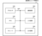
- FIG. 21 is a diagram showing an example of the hardware configuration of a base station and a user terminal according to one embodiment.
- the above-mentioned base station 10 and user terminal 20 may be physically configured as a computer device including a processor 1001, a memory 1002, a storage 1003, a communication device 1004, an input device 1005, an output device 1006, a bus 1007, etc.
- the numerology may be a communication parameter that is applied to at least one of the transmission and reception of a signal or channel.
- the numerology may indicate, for example, at least one of the following: SubCarrier Spacing (SCS), bandwidth, symbol length, cyclic prefix length, Transmission Time Interval (TTI), number of symbols per TTI, radio frame configuration, a specific filtering process performed by the transceiver in the frequency domain, a specific windowing process performed by the transceiver in the time domain, etc.
- SCS SubCarrier Spacing
- TTI Transmission Time Interval
- radio frame configuration a specific filtering process performed by the transceiver in the frequency domain
- a specific windowing process performed by the transceiver in the time domain etc.
- the TTI may be a transmission time unit for a channel-coded data packet (transport block), a code block, a code word, etc., or may be a processing unit for scheduling, link adaptation, etc.
- the time interval e.g., the number of symbols
- the time interval in which a transport block, a code block, a code word, etc. is actually mapped may be shorter than the TTI.
- one or more TTIs may be the minimum time unit of scheduling.
- the number of slots (minislots) that constitute the minimum time unit of scheduling may be controlled.
- a resource block is a resource allocation unit in the time domain and frequency domain, and may include one or more consecutive subcarriers in the frequency domain.
- the number of subcarriers included in an RB may be the same regardless of numerology, and may be, for example, 12.
- the number of subcarriers included in an RB may be determined based on numerology.
- an RB may include one or more symbols in the time domain and may be one slot, one minislot, one subframe, or one TTI in length.
- One TTI, one subframe, etc. may each be composed of one or more resource blocks.
- one or more RBs may be referred to as a physical resource block (PRB), a sub-carrier group (SCG), a resource element group (REG), a PRB pair, an RB pair, etc.
- PRB physical resource block
- SCG sub-carrier group
- REG resource element group
- PRB pair an RB pair, etc.
- a resource block may be composed of one or more resource elements (REs).
- REs resource elements
- one RE may be a radio resource area of one subcarrier and one symbol.
- a Bandwidth Part which may also be referred to as a partial bandwidth, may represent a subset of contiguous common resource blocks (RBs) for a given numerology on a given carrier, where the common RBs may be identified by an index of the RB relative to a common reference point of the carrier.
- PRBs may be defined in a BWP and numbered within the BWP.
- the BWP may include a UL BWP (BWP for UL) and a DL BWP (BWP for DL).
- BWP UL BWP
- BWP for DL DL BWP
- One or more BWPs may be configured for a UE within one carrier.
- At least one of the configured BWPs may be active, and the UE may not expect to transmit or receive a given signal/channel outside the active BWP.
- BWP bitmap
- radio frames, subframes, slots, minislots, and symbols are merely examples.
- the number of subframes included in a radio frame, the number of slots per subframe or radio frame, the number of minislots included in a slot, the number of symbols and RBs included in a slot or minislot, the number of subcarriers included in an RB, as well as the number of symbols in a TTI, the symbol length, and the cyclic prefix (CP) length can be changed in various ways.
- the information, parameters, etc. described in this disclosure may be represented using absolute values, may be represented using relative values from a predetermined value, or may be represented using other corresponding information.
- a radio resource may be indicated by a predetermined index.
- the names used for parameters and the like in this disclosure are not limiting in any respect. Furthermore, the formulas and the like using these parameters may differ from those explicitly disclosed in this disclosure.
- the various channels (PUCCH, PDCCH, etc.) and information elements may be identified by any suitable names, and the various names assigned to these various channels and information elements are not limiting in any respect.
- the information, signals, etc. described in this disclosure may be represented using any of a variety of different technologies.
- the data, instructions, commands, information, signals, bits, symbols, chips, etc. that may be referred to throughout the above description may be represented by voltages, currents, electromagnetic waves, magnetic fields or magnetic particles, optical fields or photons, or any combination thereof.
- Input/output information, signals, etc. may be stored in a specific location (e.g., memory) or may be managed using a management table. Input/output information, signals, etc. may be overwritten, updated, or added to. Output information, signals, etc. may be deleted. Input information, signals, etc. may be transmitted to another device.
- a specific location e.g., memory
- Input/output information, signals, etc. may be overwritten, updated, or added to.
- Output information, signals, etc. may be deleted.
- Input information, signals, etc. may be transmitted to another device.
- the notification of information is not limited to the aspects/embodiments described in this disclosure, and may be performed using other methods.
- the notification of information in this disclosure may be performed by physical layer signaling (e.g., Downlink Control Information (DCI), Uplink Control Information (UCI)), higher layer signaling (e.g., Radio Resource Control (RRC) signaling, broadcast information (Master Information Block (MIB), System Information Block (SIB)), etc.), Medium Access Control (MAC) signaling), other signals, or a combination of these.
- DCI Downlink Control Information
- UCI Uplink Control Information
- RRC Radio Resource Control
- MIB Master Information Block
- SIB System Information Block
- MAC Medium Access Control
- the physical layer signaling may be called Layer 1/Layer 2 (L1/L2) control information (L1/L2 control signal), L1 control information (L1 control signal), etc.
- the RRC signaling may be called an RRC message, for example, an RRC Connection Setup message, an RRC Connection Reconfiguration message, etc.
- the MAC signaling may be notified, for example, using a MAC Control Element (CE).
- CE MAC Control Element
- notification of specified information is not limited to explicit notification, but may be implicit (e.g., by not notifying the specified information or by notifying other information).
- the determination may be based on a value represented by a single bit (0 or 1), a Boolean value represented by true or false, or a comparison of numerical values (e.g., with a predetermined value).
- Software shall be construed broadly to mean instructions, instruction sets, code, code segments, program code, programs, subprograms, software modules, applications, software applications, software packages, routines, subroutines, objects, executable files, threads of execution, procedures, functions, etc., whether referred to as software, firmware, middleware, microcode, hardware description language, or otherwise.
- Software, instructions, information, etc. may also be transmitted and received via a transmission medium.
- a transmission medium For example, if the software is transmitted from a website, server, or other remote source using at least one of wired technologies (such as coaxial cable, fiber optic cable, twisted pair, Digital Subscriber Line (DSL)), and/or wireless technologies (such as infrared, microwave, etc.), then at least one of these wired and wireless technologies is included within the definition of a transmission medium.
- wired technologies such as coaxial cable, fiber optic cable, twisted pair, Digital Subscriber Line (DSL)
- wireless technologies such as infrared, microwave, etc.
- Network may refer to the devices included in the network (e.g., base stations).
- the antenna port may be interchangeably read as an antenna port for any signal/channel (e.g., a demodulation reference signal (DMRS) port).
- the resource may be interchangeably read as a resource for any signal/channel (e.g., a reference signal resource, an SRS resource, etc.).
- the resource may include time/frequency/code/space/power resources.
- the spatial domain transmission filter may include at least one of a spatial domain transmission filter and a spatial domain reception filter.
- the above groups may include, for example, at least one of a spatial relationship group, a Code Division Multiplexing (CDM) group, a Reference Signal (RS) group, a Control Resource Set (CORESET) group, a PUCCH group, an antenna port group (e.g., a DMRS port group), a layer group, a resource group, a beam group, an antenna group, a panel group, etc.
- CDM Code Division Multiplexing
- RS Reference Signal
- CORESET Control Resource Set
- beam SRS Resource Indicator (SRI), CORESET, CORESET pool, PDSCH, PUSCH, codeword (CW), transport block (TB), RS, etc. may be read as interchangeable.
- SRI SRS Resource Indicator
- CORESET CORESET pool
- PDSCH PUSCH
- codeword CW
- TB transport block
- RS etc.
- TCI state downlink TCI state
- DL TCI state downlink TCI state
- UL TCI state uplink TCI state
- unified TCI state common TCI state
- joint TCI state etc.
- QCL QCL
- QCL assumptions QCL relationship
- QCL type information QCL property/properties
- specific QCL type e.g., Type A, Type D
- specific QCL type e.g., Type A, Type D
- index identifier
- indicator indication, resource ID, etc.
- sequence list, set, group, cluster, subset, etc.
- the communication module 60 is a communication device that can be controlled by the microprocessor 61 of the electronic control unit 49 and can communicate with an external device. For example, it transmits and receives various information to and from the external device via wireless communication.
- the communication module 60 may be located either inside or outside the electronic control unit 49.
- the external device may be, for example, the above-mentioned base station 10 or user terminal 20.
- the communication module 60 may also be, for example, at least one of the above-mentioned base station 10 and user terminal 20 (it may function as at least one of the base station 10 and user terminal 20).
- the communication module 60 may transmit at least one of the signals from the various sensors 50-58 described above input to the electronic control unit 49, information obtained based on the signals, and information based on input from the outside (user) obtained via the information service unit 59 to an external device via wireless communication.
- the electronic control unit 49, the various sensors 50-58, the information service unit 59, etc. may be referred to as input units that accept input.
- the PUSCH transmitted by the communication module 60 may include information based on the above input.
- the communication module 60 receives various information (traffic information, signal information, vehicle distance information, etc.) transmitted from an external device and displays it on an information service unit 59 provided in the vehicle.
- the information service unit 59 may also be called an output unit that outputs information (for example, outputs information to a device such as a display or speaker based on the PDSCH (or data/information decoded from the PDSCH) received by the communication module 60).
- the communication module 60 also stores various information received from external devices in memory 62 that can be used by the microprocessor 61. Based on the information stored in memory 62, the microprocessor 61 may control the drive unit 41, steering unit 42, accelerator pedal 43, brake pedal 44, shift lever 45, left and right front wheels 46, left and right rear wheels 47, axles 48, various sensors 50-58, and the like provided on the vehicle 40.
- the base station in the present disclosure may be read as a user terminal.
- each aspect/embodiment of the present disclosure may be applied to a configuration in which communication between a base station and a user terminal is replaced with communication between multiple user terminals (which may be called, for example, Device-to-Device (D2D), Vehicle-to-Everything (V2X), etc.).
- the user terminal 20 may be configured to have the functions of the base station 10 described above.
- terms such as "uplink” and "downlink” may be read as terms corresponding to terminal-to-terminal communication (for example, "sidelink").
- the uplink channel, downlink channel, etc. may be read as the sidelink channel.
- the user terminal in this disclosure may be interpreted as a base station.
- the base station 10 may be configured to have the functions of the user terminal 20 described above.
- operations that are described as being performed by a base station may in some cases be performed by its upper node.
- a network that includes one or more network nodes having base stations, it is clear that various operations performed for communication with terminals may be performed by the base station, one or more network nodes other than the base station (such as, but not limited to, a Mobility Management Entity (MME) or a Serving-Gateway (S-GW)), or a combination of these.
- MME Mobility Management Entity
- S-GW Serving-Gateway
- each aspect/embodiment described in this disclosure may be used alone, in combination, or switched between depending on the implementation.
- the processing procedures, sequences, flow charts, etc. of each aspect/embodiment described in this disclosure may be rearranged as long as there is no inconsistency.
- the methods described in this disclosure present elements of various steps in an exemplary order, and are not limited to the particular order presented.
- LTE Long Term Evolution
- LTE-A LTE-Advanced
- LTE-B LTE-Beyond
- SUPER 3G IMT-Advanced
- 4th generation mobile communication system 4th generation mobile communication system
- 5G 5th generation mobile communication system
- 6G 6th generation mobile communication system
- xG x is, for example, an integer or decimal
- Future Radio Access FX
- GSM Global System for Mobile communications
- CDMA2000 Code Division Multiple Access
- UMB Ultra Mobile Broadband
- IEEE 802.11 Wi-Fi
- IEEE 802.16 WiMAX (registered trademark)
- IEEE 802.20 Ultra-Wide Band (UWB), Bluetooth (registered trademark), and other appropriate wireless communication methods, as well as next-generation systems that are expanded, modified, created
- the phrase “based on” does not mean “based only on,” unless expressly stated otherwise. In other words, the phrase “based on” means both “based only on” and “based at least on.”
- any reference to an element using a designation such as "first,” “second,” etc., used in this disclosure does not generally limit the quantity or order of those elements. These designations may be used in this disclosure as a convenient method of distinguishing between two or more elements. Thus, a reference to a first and second element does not imply that only two elements may be employed or that the first element must precede the second element in some way.
- determining may encompass a wide variety of actions. For example, “determining” may be considered to be judging, calculating, computing, processing, deriving, investigating, looking up, search, inquiry (e.g., looking in a table, database, or other data structure), ascertaining, etc.
- judgment (decision) may be considered to mean “judging (deciding)” resolving, selecting, choosing, establishing, comparing, etc.
- judgment (decision) may be considered to mean “judging (deciding)” some kind of action.
- judgment (decision) may be read as interchangeably with the actions described above.
- a and B are different may mean “A and B are different from each other.”
- the term may also mean “A and B are each different from C.”
- Terms such as “separate” and “combined” may also be interpreted in the same way as “different.”
Landscapes
- Engineering & Computer Science (AREA)
- Computer Networks & Wireless Communication (AREA)
- Signal Processing (AREA)
- Mobile Radio Communication Systems (AREA)
Priority Applications (3)
| Application Number | Priority Date | Filing Date | Title |
|---|---|---|---|
| CN202480064832.1A CN122003939A (zh) | 2023-10-10 | 2024-10-01 | 终端、无线通信方法以及基站 |
| JP2025551441A JPWO2025079463A1 (cg-RX-API-DMAC7.html) | 2023-10-10 | 2024-10-01 | |
| EP24877061.2A EP4794422A1 (en) | 2023-10-10 | 2024-10-01 | Terminal, wireless communication method, and base station |
Applications Claiming Priority (2)
| Application Number | Priority Date | Filing Date | Title |
|---|---|---|---|
| JP2023175043 | 2023-10-10 | ||
| JP2023-175043 | 2023-10-10 |
Publications (1)
| Publication Number | Publication Date |
|---|---|
| WO2025079463A1 true WO2025079463A1 (ja) | 2025-04-17 |
Family
ID=95395850
Family Applications (1)
| Application Number | Title | Priority Date | Filing Date |
|---|---|---|---|
| PCT/JP2024/035137 Ceased WO2025079463A1 (ja) | 2023-10-10 | 2024-10-01 | 端末、無線通信方法及び基地局 |
Country Status (4)
| Country | Link |
|---|---|
| EP (1) | EP4794422A1 (cg-RX-API-DMAC7.html) |
| JP (1) | JPWO2025079463A1 (cg-RX-API-DMAC7.html) |
| CN (1) | CN122003939A (cg-RX-API-DMAC7.html) |
| WO (1) | WO2025079463A1 (cg-RX-API-DMAC7.html) |
Citations (1)
| Publication number | Priority date | Publication date | Assignee | Title |
|---|---|---|---|---|
| JP2023175043A (ja) | 2019-12-29 | 2023-12-08 | 株式会社三洋物産 | 遊技機 |
-
2024
- 2024-10-01 JP JP2025551441A patent/JPWO2025079463A1/ja active Pending
- 2024-10-01 CN CN202480064832.1A patent/CN122003939A/zh active Pending
- 2024-10-01 EP EP24877061.2A patent/EP4794422A1/en active Pending
- 2024-10-01 WO PCT/JP2024/035137 patent/WO2025079463A1/ja not_active Ceased
Patent Citations (1)
| Publication number | Priority date | Publication date | Assignee | Title |
|---|---|---|---|---|
| JP2023175043A (ja) | 2019-12-29 | 2023-12-08 | 株式会社三洋物産 | 遊技機 |
Non-Patent Citations (3)
| Title |
|---|
| "Evolved Universal Terrestrial Radio Access (E-UTRA) and Evolved Universal Terrestrial Radio Access Network (E-UTRAN); Overall description; Stage 2 (Release 8", 3GPP TS 36.300 V8.12.0, April 2010 (2010-04-01) |
| CLAES TIDESTAV, ERICSSON: "Maintenance of TA management for LTM", 3GPP DRAFT; R1-2309162; TYPE DISCUSSION; NR_MOB_ENH2-CORE, 3RD GENERATION PARTNERSHIP PROJECT (3GPP), MOBILE COMPETENCE CENTRE ; 650, ROUTE DES LUCIOLES ; F-06921 SOPHIA-ANTIPOLIS CEDEX ; FRANCE, vol. RAN WG1, no. Xiamen, CN; 20231009 - 20231013, 29 September 2023 (2023-09-29), Mobile Competence Centre ; 650, route des Lucioles ; F-06921 Sophia-Antipolis Cedex ; France, XP052526882 * |
| YAN CHENG, HUAWEI, HISILICON: "Maintenance of TA enhancement for UL M-TRP transmission", 3GPP DRAFT; R1-2308924; TYPE DISCUSSION; NR_MIMO_EVO_DL_UL-CORE, 3RD GENERATION PARTNERSHIP PROJECT (3GPP), MOBILE COMPETENCE CENTRE ; 650, ROUTE DES LUCIOLES ; F-06921 SOPHIA-ANTIPOLIS CEDEX ; FRANCE, vol. RAN WG1, no. Xiamen, CN; 20231009 - 20231013, 29 September 2023 (2023-09-29), Mobile Competence Centre ; 650, route des Lucioles ; F-06921 Sophia-Antipolis Cedex ; France, XP052526646 * |
Also Published As
| Publication number | Publication date |
|---|---|
| JPWO2025079463A1 (cg-RX-API-DMAC7.html) | 2025-04-17 |
| CN122003939A (zh) | 2026-05-08 |
| EP4794422A1 (en) | 2026-08-19 |
Similar Documents
| Publication | Publication Date | Title |
|---|---|---|
| WO2024075273A1 (ja) | 端末、無線通信方法及び基地局 | |
| WO2024242098A1 (ja) | 端末、無線通信方法及び基地局 | |
| WO2024209672A1 (ja) | 端末、無線通信方法及び基地局 | |
| WO2024095481A1 (ja) | 端末、無線通信方法及び基地局 | |
| WO2025041561A1 (ja) | 端末、無線通信方法及び基地局 | |
| WO2024219456A1 (ja) | 端末、無線通信方法及び基地局 | |
| WO2024106365A1 (ja) | 端末、無線通信方法及び基地局 | |
| WO2024236645A1 (ja) | 端末、無線通信方法及び基地局 | |
| WO2024236635A1 (ja) | 端末、無線通信方法及び基地局 | |
| WO2024176337A1 (ja) | 端末、無線通信方法及び基地局 | |
| WO2024176447A1 (ja) | 端末、無線通信方法及び基地局 | |
| WO2024069840A1 (ja) | 端末、無線通信方法及び基地局 | |
| WO2025069428A1 (ja) | 端末、無線通信方法及び基地局 | |
| WO2025041562A1 (ja) | 端末、無線通信方法及び基地局 | |
| WO2025079464A1 (ja) | 端末、無線通信方法及び基地局 | |
| WO2024225242A1 (ja) | 端末、無線通信方法及び基地局 | |
| WO2024262041A1 (ja) | 端末、無線通信方法及び基地局 | |
| WO2024262040A1 (ja) | 端末、無線通信方法及び基地局 | |
| WO2025041762A1 (ja) | 端末、無線通信方法及び基地局 | |
| WO2025079510A1 (ja) | 端末、無線通信方法及び基地局 | |
| WO2024257314A1 (ja) | 端末、無線通信方法及び基地局 | |
| WO2024257317A1 (ja) | 端末、無線通信方法及び基地局 | |
| WO2024236613A1 (ja) | 端末、無線通信方法及び基地局 | |
| WO2024257316A1 (ja) | 端末、無線通信方法及び基地局 | |
| WO2024181531A1 (ja) | 端末、無線通信方法及び基地局 |
Legal Events
| Date | Code | Title | Description |
|---|---|---|---|
| 121 | Ep: the epo has been informed by wipo that ep was designated in this application |
Ref document number: 24877061 Country of ref document: EP Kind code of ref document: A1 |
|
| ENP | Entry into the national phase |
Ref document number: 2025551441 Country of ref document: JP Kind code of ref document: A |
|
| WWE | Wipo information: entry into national phase |
Ref document number: 2025551441 Country of ref document: JP |
|
| NENP | Non-entry into the national phase |
Ref country code: DE |