WO2025079211A1 - アクセスポイント及び端末装置 - Google Patents
アクセスポイント及び端末装置 Download PDFInfo
- Publication number
- WO2025079211A1 WO2025079211A1 PCT/JP2023/037066 JP2023037066W WO2025079211A1 WO 2025079211 A1 WO2025079211 A1 WO 2025079211A1 JP 2023037066 W JP2023037066 W JP 2023037066W WO 2025079211 A1 WO2025079211 A1 WO 2025079211A1
- Authority
- WO
- WIPO (PCT)
- Prior art keywords
- twt
- access point
- terminal device
- processing unit
- link
- Prior art date
- Legal status (The legal status is an assumption and is not a legal conclusion. Google has not performed a legal analysis and makes no representation as to the accuracy of the status listed.)
- Ceased
Links
Images




Classifications
-
- H—ELECTRICITY
- H04—ELECTRIC COMMUNICATION TECHNIQUE
- H04L—TRANSMISSION OF DIGITAL INFORMATION, e.g. TELEGRAPHIC COMMUNICATION
- H04L47/00—Traffic control in data switching networks
- H04L47/10—Flow control; Congestion control
- H04L47/24—Traffic characterised by specific attributes, e.g. priority or QoS
-
- H—ELECTRICITY
- H04—ELECTRIC COMMUNICATION TECHNIQUE
- H04L—TRANSMISSION OF DIGITAL INFORMATION, e.g. TELEGRAPHIC COMMUNICATION
- H04L47/00—Traffic control in data switching networks
- H04L47/50—Queue scheduling
- H04L47/62—Queue scheduling characterised by scheduling criteria
- H04L47/625—Queue scheduling characterised by scheduling criteria for service slots or service orders
- H04L47/6275—Queue scheduling characterised by scheduling criteria for service slots or service orders based on priority
Definitions
- the embodiment relates to an access point and a terminal device.
- a wireless LAN local area network
- a terminal device can access a network via an access point.
- IEEE 802.11be mentions multi-link transmission, in which multiple links (transmission paths) with different frequency channels are established between a terminal device and an access point.
- multi-link transmission multiple APs (affiliated access points) equipped in the same housing, called an AP_MLD (access point multi-link device), and multiple STAs (affiliated STAs) equipped in the same housing, called a non-AP_MLD (non-access point multi-link device), form pairs and communicate.
- AP_MLD access point multi-link device
- STAs affiliated STAs
- non-AP_MLD non-access point multi-link device
- the R-TWT (restricted target wake time) function is also known as a method for transmitting and receiving low-latency traffic between an access point and a terminal device.
- An access point using the R-TWT function sets a service period (R-TWT SP) at a period corresponding to the required latency of the low-latency traffic, and notifies the terminal device of the set service period using a management frame or action frame such as a beacon. Then, when a terminal device (low-latency terminal) that handles low-latency traffic detects the allocation of an R-TWT SP to itself by a received beacon or the like, it deterministically transmits low-latency traffic to the access point.
- a pair of an affiliated AP and an affiliated STA can perform a TWT agreement, and thus a TWT agreement can be set up for all links that make up the multilink.
- An information and communication system using the R-TWT function can reduce the delay and jitter of low-latency traffic.
- the R-TWT function is set independently for each link or for the transmission path to each access point. Furthermore, the period during which low-latency traffic has priority when transmitting traffic is only at the start of the R-TWT SP. For this reason, if scheduled low-latency traffic cannot be transmitted at the start of the R-TWT SP due to interference, etc., or if communication of other low-latency traffic or non-low-latency traffic is concentrated on a link with high channel utilization, the communication of the low-latency traffic scheduled to be transmitted may be impeded. In such cases, the required delay of the low-latency traffic may not be met.
- the present invention was made in light of the above circumstances, and its purpose is to provide an access point and terminal device that can meet the delay requirements of low-latency traffic.
- the access point of the embodiment is configured to transmit information between the access point and a terminal device using a plurality of wireless links including a first wireless link and a second wireless link.
- the access point includes a management unit configured to set a service period for preferentially transmitting low-latency traffic to at least one of the plurality of wireless links.
- the management unit schedules a common service period for each of the first wireless link and the second wireless link based on the first service period, and notifies the terminal device of schedule information including information regarding the common service period.
- FIG. 1 is a block diagram showing an example of the overall configuration of an information communication system according to the first embodiment.
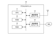
- FIG. 2 is a block diagram showing an example of a hardware configuration of an access point included in the information communication system according to the first embodiment.
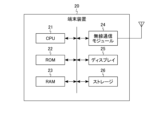
- FIG. 3 is a block diagram showing an example of a hardware configuration of a terminal device included in the information communication system according to the first embodiment.
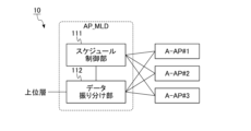
- FIG. 4 is a block diagram showing an example of a functional configuration of an access point included in the information communication system according to the first embodiment.
- FIG. 5 is a block diagram showing an example of the functional configuration of an A-AP included in an access point included in the information communication system according to the first embodiment.
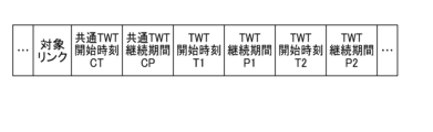
- FIG. 6 is a block diagram showing an example of a format of a beacon signal generated by a beacon control unit of an A-AP in an access point included in the information communication system according to the first embodiment.
- FIG. 7 is a block diagram showing an example of the functional configuration of a transceiver unit of an A-AP in an access point included in the information communication system according to the first embodiment.
- FIG. 8 is a block diagram showing an example of a functional configuration of a terminal device included in the information communication system according to the first embodiment.
- FIG. 9 is a block diagram showing an example of the functional configuration of an A-STA included in a terminal device included in the information communication system according to the first embodiment.
- FIG. 10 is a block diagram showing an example of the functional configuration of a transceiver unit of an A-STA in a terminal device provided in the information communication system according to the first embodiment.
- FIG. 11 is a time chart showing an overview of the R-TWT function in the information communication system according to the first embodiment.
- FIG. 12 is a flowchart showing an example of a method of using the R-TWT function in the information communication system according to the first embodiment.
- FIG. 13 is a time chart showing a specific example of communication using the R-TWT function in the information communication system according to the first embodiment.
- FIG. 14 is a block diagram showing an example of the overall configuration of an information communication system according to the second embodiment.
- FIG. 15 is a block diagram showing an example of a functional configuration of a sharing access point included in the information communication system according to the second embodiment.
- FIG. 16 is a table showing an example of information managed by a management unit of a sharing access point included in an information communication system according to the second embodiment.
- FIG. 17 is a block diagram showing an example of a functional configuration of a shared access point included in the information communication system according to the second embodiment.
- FIG. 18 is a flowchart showing an example of a method for setting up an R-TWT function in an information communication system according to the second embodiment.
- FIG. 19 is a flowchart showing an example of a method of using the R-TWT function in the information communication system according to the second embodiment.
- FIG. 20 is a time chart showing a specific example of communication using the R-TWT function in the information communication system according to the second embodiment.
- an access point and a terminal device establish a multi-link connection. Then, the R-TWT service period scheduled for each link is standardized based on the R-TWT service period for transmitting the highest priority low latency traffic. Details of the information communication system 1 according to the first embodiment are described below.
- FIG. 1 is a block diagram showing an example of the overall configuration of an information communication system 1 according to the first embodiment.
- the information communication system 1 includes, for example, an access point 10 and a terminal device 20.
- the access point 10 is a type of wireless LAN access point.
- the access point 10 is connected to the network NW by wire or wirelessly, and is configured to perform wired or wireless communication with a server (not shown) on the network NW.
- the access point 10 is also connected wirelessly to the terminal device 20, and is configured to perform wireless communication with the terminal device 20.
- the terminal device 20 is a wireless terminal such as a smartphone or a PC (Personal Computer).
- the terminal device 20 is arranged so as to be included in the communication area of the access point 10.
- the terminal device 20 is wirelessly connected to the access point 10 and configured to wirelessly communicate with the access point 10.
- the wireless communication used in the information and communication system 1 complies with, for example, the IEEE 802.11 standard.
- the IEEE 802.11 standard has a wireless communication function based on the OSI (Open Systems Interconnection) reference model. In the OSI reference model, the wireless communication function is divided into seven layers (first layer: physical layer, second layer: data link layer, third layer: network layer, fourth layer: transport layer, fifth layer: session layer, sixth layer: presentation layer, seventh layer: application layer).
- the data link layer includes an LLC (Logical Link Control) sublayer and a MAC (Media Access Control) sublayer.
- the frequency bands used in the wireless communication of the information and communication system 1 may be, for example, the 2.4 GHz band, the 5 GHz band, the 6 GHz band, the 45 GHz band, and the 60 GHz band. Each frequency band is assigned multiple channels.
- each of the access point 10 and the terminal device 20 supports the R-TWT (restricted target wake time) function.
- the R-TWT function is a function that assigns to the terminal device 20 a service period during which traffic requiring low latency can be preferentially exchanged.
- the service period set by the R-TWT function is called the “R-TWT service period (R-TWT SP)" and the traffic requiring low latency is called "low latency traffic.”
- An access point 10 that uses the R-TWT function can assign an R-TWT SP to a link and give priority to frame exchange opportunities to terminal equipment 20.
- a frame exchange opportunity corresponds to an opportunity to transmit traffic (data) through frame exchange.
- the terminal equipment 20 transmits low-latency traffic to the access point 10 based on receiving a trigger frame from the access point 10 at the R-TWT SP.
- the R-TWT function can improve the latency of low-latency traffic by giving priority to transmitting low-latency traffic of the terminal equipment 20 at the R-TWT SP.
- each of the access point 10 and the terminal device 20 supports multi-link communication using multiple channels (links) as a communication method.
- links channels
- the access point 10 includes, for example, an AP_MLD (access point multi-link device) and multiple affiliated APs (A-APs).
- the AP_MLD is a multi-link device (MLD) that manages the link state and wireless communication of each of the multiple A-APs.
- the AP_MLD can also perform processing for establishing a multi-link between the access point 10 and the terminal device 20.
- Each A-AP corresponds to a wireless signal processing unit that can establish a wireless link with the terminal device 20.
- the access point 10 includes A-AP#1, A-AP#2, and A-AP#3 as the multiple A-APs.
- the terminal device 20 includes, for example, a non-AP_MLD (non-access point multi-link device) and multiple affiliated stations (A-STAs).
- the non-AP_MLD is a multi-link device (MLD) that manages the link state and wireless communication of each of the multiple A-STAs.
- the non-AP_MLD can also perform processing to establish a multi-link between the access point 10 and the terminal device 20.
- Each A-STA corresponds to a wireless signal processing unit that can establish a wireless link with the access point 10.
- the terminal device 20 includes A-STA#1, A-STA#2, and A-STA#3 as the multiple A-STAs.
- A-AP#1 to #3 of the access point 10 respectively establish links with A-STA#1 to #3 of the terminal device 20.
- the link between A-AP#1 and A-STA#1 is referred to as "link#1".
- the link between A-AP#2 and A-STA#2 is referred to as "link#2".
- the link between A-AP#3 and A-STA#3 is referred to as "link#3".
- different channels are assigned to A-AP#1 to #3. The same frequency band may be used for A-AP#1 to #3, or different frequency bands may be used.
- different channels are assigned to A-STA#1 to #3. The same frequency band may be used for A-STA#1 to #3, or different frequency bands may be used.
- the AP_MLD of the access point 10 can schedule the R-TWT SP so that the R-TWT SP is synchronized on multiple links.
- the AP_MLD then assigns the scheduled R-TWT SP to each link and outputs low-latency data to the A-AP corresponding to the link to which the R-TWT SP is assigned.
- the AP_MLD also determines whether or not it overlaps with other R-TWT SPs that have been scheduled in advance, and decides whether or not to schedule it.
- Each A-AP broadcasts the schedule information of the R-TWT SP set by the AP_MLD as a wireless signal, and sets the R-TWT SP according to that schedule information.
- the A-AP also transmits data input from the AP_MLD as a wireless signal, and outputs the received wireless signal to the AP_MLD.
- the non-AP_MLD of the terminal device 20 When the R-TWT function is used in a multi-link, the non-AP_MLD of the terminal device 20 outputs the low-latency data from the higher level to the A-STA corresponding to the link to which the R-TWT SP is assigned, according to the schedule information notified by the access point 10. Each A-STA outputs the schedule information and data received as a wireless signal to the non-AP_MLD, and outputs the data input from the non-AP_MLD as a wireless signal.
- the AP_MLD may synchronize the transmission time of each link.
- the master clock held by the AP_MLD may be referenced, or the time information notified from the network NW may be referenced.
- the non-AP_MLD may synchronize the transmission time of each link.
- the master clock held by the non-AP_MLD may be referenced, or the time information notified from the AP-MLD of the access point 10 may be referenced.
- a more detailed functional configuration of each of the access point 10 and the terminal device 20 will be described later.
- FIG. 2 is a block diagram showing an example of a hardware configuration of the access point 10 included in the information communication system 1 according to the first embodiment.
- the access point 10 includes, for example, a CPU (Central Processing Unit) 11, a ROM (Read Only Memory) 12, a RAM (Random Access Memory) 13, a wireless communication module 14, and a wired communication module 15.
- a CPU Central Processing Unit
- ROM Read Only Memory
- RAM Random Access Memory
- the CPU 11 is an integrated circuit capable of executing various programs, and controls the overall operation of the access point 10.
- the ROM 12 is, for example, a non-volatile semiconductor memory, and stores programs and control data for controlling the access point 10.
- the RAM 13 is, for example, a volatile semiconductor memory, and is used as a working area for the CPU 11.
- the wireless communication module 14 is configured to be able to send and receive wireless signals via an antenna, and is a circuit used for sending and receiving data, etc. with the terminal device 20.
- the wired communication module 15 is a circuit used for sending and receiving data, etc. via wired signals, and is configured to be connectable to the network NW.
- the access point 10 may have other hardware configurations.
- the access point 10 may be wirelessly connected to the network NW.
- the wired communication module 15 may be omitted from the access point 10.
- the antenna may be built into the access point 10 or may be externally connected.
- the CPU 11 may be called a "processor.”
- the wireless communication module 14 may be called a "communication circuit.”
- FIG. 3 is a block diagram showing an example of a hardware configuration of the terminal device 20 included in the information communication system 1 according to the first embodiment.
- the terminal device 20 includes, for example, a CPU 21, a ROM 22, a RAM 23, a wireless communication module 24, a display 25, and a storage 26.
- the CPU 21 is an integrated circuit capable of executing various programs, and controls the overall operation of the terminal device 20.
- the ROM 22 is, for example, a non-volatile semiconductor memory, and stores programs and control data for controlling the terminal device 20.
- the RAM 23 is, for example, a volatile semiconductor memory, and is used as a working area for the CPU 21.
- the wireless communication module 24 is configured to be able to send and receive wireless signals via an antenna, and is a circuit used for sending and receiving data to and from the access point 10.
- the display 25 displays, for example, a GUI (Graphical User Interface) corresponding to application software, etc.
- the storage 26 is a non-volatile storage device, and stores, for example, system software for the terminal device 20, etc.
- the terminal device 20 may have other hardware configurations.
- the display 25 may be omitted from the terminal device 20.
- the display 25 may have a function as an input interface for the terminal device 20.
- the antenna may be built into the terminal device 20 or may be externally connected.
- the CPU 21 may be called a "processor.”
- the wireless communication module 24 may be called a "communication circuit.”
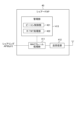
- FIG. 4 is a block diagram showing an example of the functional configuration of the access point 10 included in the information communication system 1 according to the first embodiment.
- the AP_MLD of the access point 10 includes, for example, a schedule control unit 111 and a data distribution unit 112.
- the schedule control unit 111 controls (manages) the schedule of the R-TWT SP to be assigned to each link that constitutes the multi-link.
- the schedule control unit 111 has a function of scheduling the R-TWT SP for the highest priority low-latency data and assigning it to each link.
- the schedule control unit 111 then outputs schedule information including the determined schedule to each A-AP and the data distribution unit 112.
- the schedule control unit 111 can also calculate the longest R-TWT SP that does not include multiple R-TWT SPs and schedule it as a common R-TWT SP.
- the schedule control unit 111 has a function of synchronizing the internal time of each A-AP.
- the data distribution unit 112 outputs low-latency data (low-latency traffic) to the A-AP corresponding to the link to which the R-TWT SP is assigned, when low-latency data (low-latency traffic) is input from the upper layer. For example, based on the schedule information of the R-TWT SP notified by the schedule control unit 111, it determines the A-AP to which the R-TWT SP is set at the time when the data is input, and outputs the low-latency data to that A-AP.
- the schedule control unit 111 may request information about periods during which transmission is not possible from each A-AP constituting the multi-link, and based on the response from each A-AP, adjust (e.g., shorten) the timing of the R-TWT SPs assigned to each link so as to prevent collisions. If a collision occurs, the schedule control unit 111 may not perform scheduling on that link. Possible periods during which transmission is not possible include reservations by other periodic R-TWT SPs on each link, reservations by other BSSs (basic service sets) using the same channel, and reservations by NAVs (network allocation vectors).
- each A-AP includes, for example, a beacon control unit 121, an R-TWT control unit 122, a frame processing unit 123, and a transmission/reception unit 124.
- the beacon control unit 121 When the beacon control unit 121 announces the schedule of the R-TWT SP of all links only on the primary link set in the multi-link, it causes other links to announce only the schedule of the R-TWT SP corresponding to that link. If the beacon signal received from another access point 10 includes settings such as R-TWT SP, the beacon control unit 121 notifies the schedule control unit 111 of the settings.
- the frame processing unit 123 is a functional block that executes processing corresponding to the MAC sublayer of the second layer.
- the frame processing unit 123 adds a MAC header to generate a MAC frame and outputs it to the transmission/reception unit 124.
- the frame processing unit 123 transfers the input trigger frame to the transmission/reception unit 124.
- the frame processing unit 123 may be configured to generate a beacon signal or a trigger frame based on information input from the beacon control unit 121 or the R-TWT control unit 122.
- the frame processing unit 123 processes the MAC header and outputs the input frame to the data allocation unit 112 or the beacon control unit 121 depending on the frame type. For example, when a data frame is input from the transmitting/receiving unit 124, the frame processing unit 123 outputs the input frame to the data allocation unit 112. When a control frame including schedule information for the R-TWT function is input from the transmitting/receiving unit 124, the frame processing unit 123 outputs the input frame to the beacon control unit 121.
- the transceiver 124 is a functional block that executes processing corresponding to the first layer.
- the transceiver 124 generates a wireless frame by adding a preamble, etc. to the MAC frame input from the frame processing unit 123, and converts the generated wireless frame into a wireless signal.
- the transceiver 124 then transmits (radiates) the converted wireless signal via an antenna.
- the transceiver 124 also extracts the MAC frame from the wireless frame received by the antenna, and outputs the extracted MAC frame to the frame processing unit 123.
- (2: Beacon Signal Configuration) 6 is a block diagram showing an example of a format of a beacon signal generated by the beacon control unit 121 of the A-AP in the access point 10 included in the information communication system 1 according to the first embodiment.
- the beacon signal includes information on, for example, a target link, a common TWT start time CT, a common TWT duration CP, a TWT start time T1, a TWT duration P1, a TWT start time T2, and a TWT duration P2.
- the target link indicates the identifier of the link to which the R-TWT SP is to be assigned.
- the link identifier is specified, for example, by the A-STA identifier.
- the target link information may include information of a single link or may include information of multiple links.
- the common TWT start time CT indicates the start time of the common R-TWT SP assigned to the associated target link.
- the common TWT duration CP indicates the duration of the common R-TWT SP assigned to the associated target link.
- Each of the pair of the TWT start time T1 and the TWT duration P1, and the pair of the TWT start time T2 and the TWT duration P2 indicates the start time and duration for synchronously transmitting data using multiple links in the common R-TWT SP. At least one pair of the TWT start time and the TWT duration set in the common R-TWT SP may be set.
- the beacon control unit 121 may include in the beacon signal the start time (TWT start time) and duration (TWT duration) of the R-TWT SP to be copied from its own channel and set in another channel from the schedule information of the R-TWT SP input by the schedule control unit 111.
- the beacon control unit 121 may also use the beacon signal to announce the schedules of the R-TWT SP of all links.
- the beacon control unit 121 may include in the beacon signal information on the target link, TWT start time, and TWT duration for each R-TWT SP.
- the configuration of the beacon signal may be changed as appropriate depending on the configuration of the common R-TWT SP. For example, when no other R-TWT SP is set within the common R-TWT SP (i.e., when only a common R-TWT SP is set), information about the other TWT SPs (e.g., TWT start time T1, TWT duration P1, TWT start time T2, and TWT duration P2) may be omitted from the beacon signal, trigger frame, or other action frame.
- the beacon control unit 121 can uniquely specify the transmission timing by announcing the common TWT start time CT and common TWT duration CP by the beacon signal.
- the transmission/reception unit 124) 7 is a block diagram showing an example of a functional configuration of the transceiver 124 of the A-AP in the access point 10 included in the information communication system 1 according to the first embodiment.
- the functional configuration of the transceiver 124 corresponds to the channel access means (function) of the A-AP.
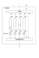
- the transceiver 124 includes, for example, a classification unit 131, queues 132A, 132B, 132C, and 132D, carrier sense execution units 133A, 133B, 133C, and 133D, and an internal collision management unit 134.
- the classification unit 131 classifies the MAC frames input from the frame processing unit 123 into a number of access categories VO (Voice), VI (Video), BE (Best Effort), BK (Background), and RT (Real Time) based on the traffic type (TID: Traffic Identifier) included in the MAC header.
- the TID is a traffic indicator and is used to identify the traffic to which the data belongs.
- MAC frames classified into the access category RT are high-priority frames such as trigger frames and low-latency traffic.
- the classification unit 131 then inputs the MAC frames corresponding to the access categories VO, VI, BE, and BK into queues 132A, 132B, 132C, and 132D, respectively.
- the queues 132A, 132B, 132C, and 132D buffer the MAC frames corresponding to the access categories VO, VI, BE, and BK, respectively. Queues 132A, 132B, 132C, and 132D are associated with carrier sense execution units 133A, 133B, 133C, and 133D, respectively.
- Each of the carrier sense execution units 133A, 133B, 133C, and 133D executes carrier sense based on CSMA/CA (Carrier Sense Multiple Access with Collision Avoidance) according to preset access parameters when data is input to the corresponding queue 132.
- the access parameters are set for each access category. For example, the access parameters are set so that the transmission of wireless signals is prioritized in the order of "VO", "VI", "BE", and "BK”.
- Each of the carrier sense execution units 133A, 133B, 133C, and 133D stops acquiring the transmission right if the channel state at the time of carrier sense is busy, and acquires the transmission right of a MAC frame if the state is idle for a predetermined time.
- the carrier sense execution unit 133 that has acquired the transmission right extracts a MAC frame from the associated queue 132 and outputs the extracted MAC frame to the internal collision management unit 134.
- the internal collision management unit 134 prevents transmission collisions when multiple carrier sense execution units 133 simultaneously acquire the right to transmit. Specifically, when multiple MAC frames are input simultaneously, the internal collision management unit 134 gives priority to outputting MAC frames of higher priority access categories.
- the MAC frames output from the internal collision management unit 134 i.e., MAC frames that have acquired access rights to a channel, are converted into wireless frames after a preamble is added, and are transmitted via an antenna.
- the classification unit 131 performs carrier sensing and then inputs the MAC frame to the internal collision management unit 134 without passing through each queue 132.
- high priority frames such as low latency traffic classified as the access category RT are processed with priority over other traffic types by performing carrier sensing without passing through each queue 132. Therefore, high priority frames can be processed with less delay than other traffic.
- the transmission/reception unit 124 may temporarily stop carrier sensing of each carrier sense execution unit 133. The transmission/reception unit 124 may generate a trigger frame based on information notified from the frame processing unit 123.
- the trigger frame and low-latency traffic input from the R-TWT control unit 122 at the start timing of the R-TWT SP are treated as access category RT with priority.
- Parameters that allow the trigger frame and low-latency data to be transmitted with priority over the access parameters of other access categories may be set.
- the trigger frame may be transmitted by interrupting other data in the queue 132 while sharing the channel access means with a high-priority access category.
- the low-latency data may be transmitted omitting the channel access means when it is determined to be an R-TWT SP, i.e., when the trigger frame has been transmitted first.
- the access parameters used in carrier sensing in the transceiver 124 of the access point 10 include, for example, CW (contention window) min, CWmax, AIFS (arbitration interframe space), and TXOP (transmission opportunity) Limit.
- the contention window is a parameter used to determine the transmission waiting time for collision avoidance.
- CWmin and CWmax indicate the minimum and maximum values of the contention window, respectively.
- AIFS aromatic interframe space
- TXOP corresponds to the channel occupancy time.
- TXOPLimit indicates the upper limit of TXOP. The shorter the CWmin and CWmax are, the easier it is for the queue 132 to obtain the transmission right. The smaller the AIFS is, the higher the priority of the queue 132 is.
- the amount of data that can be transmitted with one transmission right increases as the value of TXOPLimit increases.
- the access parameters may also be called Enhanced Distributed Channel Access (EDCA) parameters.
- EDCA Enhanced Distributed Channel Access
- the access point 10 may have other functional configurations as long as it is capable of executing the operations described below.
- the channel access function of the access point 10 may be implemented in the frame processing unit 123 rather than in the transceiver unit 124.
- the transmission priority may be determined based on the required delay of the aperiodic low latency traffic, the priority of the traffic (SCS: stream classification service), and the traffic type.
- Fig. 8 is a block diagram showing an example of the functional configuration of the terminal device 20 included in the information communication system 1 according to the first embodiment.
- the Non-AP_MLD of the terminal device 20 includes, for example, a schedule control unit 211 and a data distribution unit 212.
- the schedule control unit 211 controls (manages) the schedule of the R-TWT SP assigned to each link that constitutes the multi-link.
- the schedule control unit 211 outputs the schedule information of the R-TWT SP to the data distribution unit 212 based on the schedule information input from each A-STA and the information of the next R-TWT SP.
- the schedule control unit 211 updates the schedule of the R-TWT SP with the input schedule information.
- schedule control unit 211 updates the schedule of the R-TWT SP with the schedule information.
- the schedule control unit 211 updates the schedule information with the information.
- the schedule control unit 211 notifies the data distribution unit 212 of the updated schedule.
- the data distribution unit 212 determines the A-STA to which the R-TWT SP is set based on the schedule information of the R-TWT SP notified by the schedule control unit 211, and outputs the low-latency data to that A-STA.
- the data distribution unit 212 also outputs the data input from each A-STA to the upper layer.
- each A-STA includes, for example, a beacon processing unit 221, a frame processing unit 222, and a transmission/reception unit 223.
- the beacon processing unit 221 extracts schedule information from the beacon signal input from the frame processing unit 222 and outputs it to the schedule control unit 211. For example, the beacon processing unit 221 outputs the information of the next R-TWT SP input from the frame processing unit 222 to the schedule control unit 211, or notifies (sets) the frame processing unit 222 of the R-TWT SP linked to the channel corresponding to the A-STA. The beacon processing unit 221 may notify (set) the frame processing unit 222 of the R-TWT SP corresponding to the A-STA based on an instruction from the schedule control unit 211.
- the frame processing unit 222 is a functional block that executes processing corresponding to the MAC sublayer of the second layer.
- the frame processing unit 222 adds a MAC header to generate a MAC frame and outputs it to the transmission/reception unit 223.
- the frame processing unit 222 performs MAC header processing on the frame input from the transmission/reception unit 223, and if the frame that has undergone MAC header processing is a beacon signal, it outputs it to the beacon processing unit 221, and if it is data, it outputs it to the data distribution unit 212.
- the frame processing unit 222 sets the R-TWT SP based on the TWT duration and outputs information on the next R-TWT SP to the beacon processing unit 221.
- the frame processing unit 222 outputs data to the corresponding A-STA based on the schedule of the R-TWT SP input by the schedule control unit 211 and based on the TID, etc.
- the transceiver 223 is a functional block that executes processing corresponding to the first layer.
- the transceiver 223 generates a wireless frame by adding a preamble, etc. to the MAC frame input from the frame processing unit 222, and converts the generated wireless frame into a wireless signal.
- the transceiver 223 then transmits (radiates) the converted wireless signal via an antenna.
- the transceiver 223 also extracts the MAC frame from the wireless frame received by the antenna, and outputs the extracted MAC frame to the frame processing unit 222.
- (2: Functional configuration of the transmission/reception unit 223) 10 is a block diagram showing an example of a functional configuration of the transceiver unit 223 of the A-STA in the terminal device 20 included in the information communication system 1 according to the first embodiment.
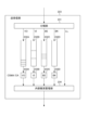
- the transceiver unit 223 includes, for example, a classification unit 231, queues 232A, 232B, 232C, and 232D, carrier sense execution units 233A, 233B, 233C, and 233D, and an internal collision management unit 234.
- the classification unit 231 classifies the MAC frames input from the frame processing unit 222 into a plurality of access categories VO, VI, BE, BK, and LL (Low Latency) based on the traffic type included in the MAC header. MAC frames classified into the access category LL are high-priority frames such as low-latency traffic.
- the classification unit 231 then inputs the MAC frames corresponding to the access categories VO, VI, BE, and BK into queues 232A, 232B, 232C, and 232D, respectively.
- the queues 232A, 232B, 232C, and 232D buffer the MAC frames corresponding to the access categories VO, VI, BE, and BK, respectively.
- the queues 232A, 232B, 232C, and 232D are associated with the carrier sense execution units 233A, 233B, 233C, and 233D, respectively.
- Each of the carrier sense execution units 233A, 233B, 233C, and 233D executes carrier sense based on CSMA/CA according to preset access parameters as data is input to the corresponding queue 232.
- Each of the carrier sense execution units 233A, 233B, 233C, and 233D stops acquiring the transmission right if the channel state at the time of carrier sense is busy, and acquires the transmission right for the MAC frame if it has been in an idle state for a predetermined period of time. After acquiring the transmission right, the carrier sense execution unit 233 extracts the MAC frame from the associated queue 232 and outputs the extracted MAC frame to the internal collision management unit 234.
- the internal collision management unit 234 prevents transmission collisions when multiple carrier sense execution units 233 simultaneously acquire the right to transmit. Specifically, when multiple MAC frames are input simultaneously, the internal collision management unit 234 gives priority to outputting MAC frames of higher priority access categories.
- the MAC frames output from the internal collision management unit 234, i.e., MAC frames that have acquired access rights to a channel, are converted into wireless frames after a preamble is added, and are transmitted via an antenna.
- the classification unit 231 performs carrier sensing and then inputs the MAC frame to the internal collision management unit 234 without passing through each queue 232.
- high priority frames such as low latency traffic classified as access category LL are processed with priority over other traffic types by performing carrier sensing without passing through each queue 232. Therefore, high priority frames can be processed with less delay than other traffic.
- the transmission/reception unit 223 may temporarily stop carrier sensing of each carrier sense execution unit 233 when transmitting a high priority frame.
- low-latency traffic input from the frame processing unit 222 is treated as an access category LL and is given priority. Parameters may be set for low-latency traffic that allow it to be transmitted with priority over the access parameters of other access categories.
- the low-latency traffic may be transmitted by interrupting other data in the queue 232 while sharing a channel access means with a high-priority access category.
- the low-latency traffic receives a trigger frame and is determined to be within the R-TWT SP, it may be transmitted by omitting the channel access means.
- the access parameters used in carrier sensing in the transceiver 223 of the terminal device 20 include, for example, CWmin, CWmax, AIFS, and TXOPLimit.
- CWmin and CWmax the easier it is for the queue 232 to obtain the transmission right.
- AIFS the higher the priority of the queue 232.
- TXOPLimit the greater the amount of data transmitted with one transmission right.
- the terminal device 20 may have other functional configurations as long as it is capable of executing the operations described below.
- the channel access function of the terminal device 20 may be implemented in the frame processing unit 222 rather than the transmission/reception unit 223.
- the transmission priority may be determined based on the required delay of the low-latency traffic, the priority of the traffic (SCS: stream classification service), and the traffic type.
- Fig. 11 is a time chart showing an overview of the R-TWT function in the information communication system 1 according to the first embodiment.
- Fig. 11 shows a processing sequence of the R-TWT function when a multi-link including three links #1 to #3 is established between the access point 10 and the terminal device 20.
- Fig. 11 shows a processing sequence of the R-TWT function when a multi-link including three links #1 to #3 is established between the access point 10 and the terminal device 20.
- the access point 10 sets a fixed period (TWT period) when setting up the R-TWT function.
- the TWT period is preferably set to match the transmission period of low-latency traffic.
- One period (TWT interval) of the TWT period includes an R-TWT SP.
- the R-TWT SP is determined, for example, by the TWT start time and the TWT duration.
- the TWT duration indicates the length of the R-TWT SP starting from the TWT start time.
- the terminal device 20 can recognize the time based on the TWT start time and the TWT period as the TWT start time of the next R-TWT service period SP.
- the TWT interval also corresponds to the interval between the TWT start times of adjacent R-TWT service periods SP.
- each link When the TWT period starts, each link simultaneously transmits (radiates) a beacon signal to notify the R-TWT SP.
- the beacon signal may include the TWT start time, TWT duration, TWT interval, transmission suppression period, etc. as management information used in the R-TWT function. This management information used in the R-TWT function may be included not only in the beacon signal but also in the multi-link probe response at the time of multi-link setup.
- the terminal device 20 receives a beacon signal, it obtains the TWT start time, TWT duration, TWT interval, etc. and notifies each A-STA.
- the R-TWT SP is set to link #3 based on the beacon signal.
- frame exchange of low-latency traffic is performed preferentially.
- a transmission suppression period may be set so as to overlap with the R-TWT SP.
- the transmission suppression period corresponds to a period during which traffic transmission by other terminal devices that are not given preferential frame exchange opportunities is suppressed or prohibited.
- the initial setting of the R-TWT function may be determined in various ways. For example, the initial setting of the R-TWT function may use traffic attributes such as the occurrence interval and data volume of the traffic notified by an application that generates low latency traffic. In this case, the access point 10 notifies a server on the network NW of the type of traffic to obtain the corresponding traffic attributes. Then, the access point 10 determines the initial setting of the R-TWT function based on the obtained traffic attributes.
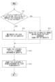
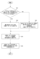
- FIG. 12 is a flowchart showing an example of a method of using the R-TWT function in the information communication system 1 according to the first embodiment.
- a method of using the R-TWT function in the information communication system 1 according to the first embodiment will be described with reference to Fig. 12.
- the AP_MLD of the access point 10 establishes a multi-link with the terminal device 20 and schedules at least one R-TWT SP, and then starts the series of processes shown in FIG. 12 (START).
- the schedule control unit 111 of the AP_MLD of the access point 10 checks whether there is an R-TWT SP that does not include multiple R-TWT SPs in a single link among the scheduled R-TWT SPs (S11).
- the schedule control unit 111 determines that there is an R-TWT SP that does not include multiple R-TWT SPs in a single link among the scheduled R-TWT SPs. If it confirms that there is no R-TWT SP that does not include multiple R-TWT SPs, it proceeds to the process of S13 (S11: NO).
- the schedule control unit 111 sets the R-TWT SP with the maximum length as the common R-TWT SP.
- the schedule control unit 111 selects the R-TWT SP with the maximum length from the R-TWT SPs extracted by the process of S11.
- the schedule control unit 111 proceeds to the process of S14.
- the schedule control unit 111 sets the period of the R-TWT SP that has the longest period that does not overlap with other R-TWT SPs as the common R-TWT SP. In other words, the schedule control unit 111 truncates the common R-TWT SP that is set based on the period in which multiple R-TWT SPs are scheduled in parallel before the next R-TWT SP so that it does not overlap with other R-TWT SPs. The schedule control unit 111 can also schedule the portion that overlaps with other R-TWT SPs as a different R-TWT SP.
- the schedule control unit 111 proceeds to the process of S14.
- the schedule control unit 111 notifies the terminal device 20 of schedule information including the common R-TWT SP.
- the schedule control unit 111 of the AP_MLD notifies the beacon control unit 121 of each A-AP of the schedule information.
- the beacon control unit 121 of each A-AP generates a beacon signal including the received schedule, and transmits (radiates) a wireless signal via the frame processing unit 123 and the transmission/reception unit 124.
- the schedule control unit 111 performs redundant transmission of high-priority low-latency traffic using the common R-TWT SP (S15). Specifically, the schedule control unit 111 notifies the data distribution unit 112 of schedule information including the common R-TWT SP.
- the data distribution unit 112 When transmitting upstream traffic, the data distribution unit 112 outputs a trigger frame that instructs the transfer of low-latency traffic to each of the A-APs to which the common R-TWT SP is assigned, for example, based on the common TWT start time.
- the data distribution unit 112 When transmitting downstream traffic, the data distribution unit 112 outputs downstream traffic to each of the A-APs to which the common R-TWT SP is assigned, for example, based on the common TWT start time.
- the AP_MLD of the access point 10 can schedule a common R-TWT SP to multiple links at the same timing, thereby enabling redundant transmission of low-latency traffic.
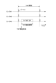
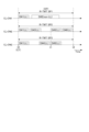
- Fig. 13 is a time chart showing a specific example of communication using the R-TWT function in the information communication system 1 according to the first embodiment.
- Fig. 13 shows a processing sequence of the R-TWT function when a multi-link including three links #1 to #3 is established between the access point 10 and the terminal device 20.
- a specific example of communication using the R-TWT function in the information communication system 1 according to the first embodiment will be described with reference to Fig. 13.
- Time t0 corresponds to the common TWT start time CT.
- transmission of data D#1 corresponding to low latency traffic (LL) begins on each of links #1 to #3. That is, data D#1 is redundantly transmitted using links #1 to #3.
- transmission of data D#2 corresponding to non-low latency traffic (non-LL) begins. In this way, non-low latency traffic can be transmitted in the R-TWT SP by utilizing a period other than the TWT start time when low latency traffic is not being transmitted.
- Time t1 corresponds to the TWT start time included in the common R-TWT SP.
- data D#2 is being transmitted in R-TWT SP1 of link #1, so data D#5 corresponding to low latency traffic is being redundantly transmitted using R-TWT SP2 and R-TWT SP3 corresponding to links #2 and #3, respectively.
- data D#6 corresponding to low latency traffic (LL) is transmitted.
- Time t2 corresponds to the end time of the common R-TWT SP.
- the information and communication system 1 when the information and communication system 1 transmits the same data in the common R-TWT SP, it synchronizes the transmission timing of the low-latency traffic in multiple links according to the traffic transmission status and the TWT start time set in the common R-TWT SP. Also, when only the common R-TWT SP is set, the information and communication system 1 uniquely synchronizes the transmission timing of the low-latency traffic in multiple links according to the common TWT start time. When upstream low-latency traffic is transmitted in the common R-TWT SP, a trigger frame is used.
- the information and communication system 1 can redundantly transmit low-latency traffic (e.g., data D#1, D#5) using the common R-TWT SPs (R-TWT SP1 to R-TWT SP3) set in each of the links #1 to #3.
- low-latency traffic e.g., data D#1, D#5
- R-TWT SP1 to R-TWT SP3 set in each of the links #1 to #3.
- redundant transmission means that the same data is transmitted in parallel using multiple links (transmission paths).
- the information and communication system 1 does not need to synchronize the transmission timing.
- the access point 10 schedules a common R-TWT SP that is a standardized R-TWT SP that transmits the highest priority low-latency traffic, based on the R-TWT SP scheduled for each link.
- the access point 10 then uses the common R-TWT SP to redundantly transmit the highest priority low-latency traffic.
- the information and communications system 1 according to the first embodiment can transmit low-latency traffic through other links that are less affected by interference.
- the information and communications system 1 according to the first embodiment can transmit low-latency traffic more reliably, and can reduce the delay and jitter of the traffic. Therefore, the information and communications system 1 according to the first embodiment can provide an access point and terminal device that can meet the required delay of low-latency traffic.
- Second embodiment In the information communication system 1A according to the second embodiment, an access point and a terminal device establish a multi-AP connection. Then, the information communication system 1A standardizes the R-TWT service period scheduled in each transmission path based on the R-TWT service period for transmitting the highest priority low latency traffic. Details of the information communication system 1A according to the second embodiment are described below.
- a plurality of access points belonging to an access point connected to a network NW cooperate with each other to perform data communication between the access point connected to the network NW and a terminal device.
- offloading is possible, which distributes data (traffic) exchanged between an access point connected to the network NW and a non-AP_MLD to a plurality of access points belonging to an access point connected to the network NW.
- an access point connected to the network NW is called a “sharing AP (sharing access point)" and a plurality of access points belonging to an access point connected to the network NW are called a “shared AP (shared access point)”.
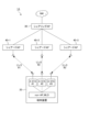
- FIG. 14 is a block diagram showing an example of the overall configuration of the information communication system 1A according to the second embodiment.
- the information communication system 1A includes a sharing AP (sharing access point) 30, a plurality of shared APs (shared access points) 40, and a terminal device 20.
- sharing AP sharing access point
- shared APs shared access points
- the sharing AP 30 is a type of wireless LAN access point.
- the sharing AP 30 is connected to the network NW by wire or wirelessly, and is configured to perform wired or wireless communication with a server (not shown) on the network NW.
- the sharing AP 30 is also connected to multiple shared APs 40 by wire or wirelessly, and is configured to perform wired or wireless communication with each of the multiple shared APs 40.
- the sharing AP 30 can establish a logical multi-AP connection with the non-AP_MLD of the terminal device 20.
- the shared AP 40 is a type of wireless LAN access point.
- the shared AP 40 is configured to perform wired or wireless communication with the sharing AP 30.
- the shared AP 40 is wirelessly connected to the A-STA of the terminal device 20 and configured to perform wireless communication with the A-STA of the terminal device 20.
- the multiple shared APs 40 are installed at locations distant from each other and have different communication areas. The communication area of each shared AP 40 may overlap with the communication areas of the other shared APs 40.
- Figure 14 illustrates an example in which a multi-AP connection is established using three shared APs 40-1, 40-2, and 40-3.
- A-STA#1 is wirelessly connected to the shared AP 40-1 (link#1)
- A-STA#2 is wirelessly connected to the shared AP 40-2 (link#2)
- A-STA#3 is wirelessly connected to the shared AP 40-3 (link#3).
- the wireless connection between the A-STA and the shared AP 40 corresponds to the connection between a pair of A-APs and A-STAs in the first embodiment.
- Each A-STA can switch its connection to another shared AP 40 as the terminal device 20 moves.
- the non-AP_MLD of the second embodiment can establish a logical multi-AP connection with the sharing AP 30 via multiple A-STAs and multiple shared APs 40, and exchange data, etc.
- the hardware configuration of the sharing AP 30 is, for example, similar to that of the access point 10 of the first embodiment.
- the hardware configuration is similar to that of the access point 10 of the first embodiment from which the wired communication module 15 is omitted.
- the hardware configuration of the terminal device 20 of the second embodiment is similar to that of the terminal device 20 of the first embodiment.
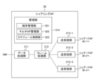
- Fig. 15 is a block diagram showing an example of the functional configuration of the sharing AP 30 included in the information communication system 1A according to the second embodiment.
- the sharing AP 30 includes, for example, a data processing unit 311, a frame processing unit 312, a plurality of transmission/reception units 313, and a management unit 314.
- the data processing unit 311 outputs data input from the network NW side via the LLC sublayer to the frame processing unit 312.
- the data processing unit 311 also outputs data input from the frame processing unit 312 to the network NW side via the LLC sublayer.
- the frame processing unit 312 exchanges management information with the management unit 314, and exchanges data with the data processing unit 311.
- the frame processing unit 312 distributes the management information and data input from the data processing unit 311 and management unit 314 to the transmission/reception unit 313 connected to the shared AP 40 that connects to the A-STA under the destination non-AP_MLD.
- the frame processing unit 312 may distribute data to the transmission/reception unit 313 according to the TID.
- the transceiver 313 is connected to the shared AP 40 by wire or wirelessly.
- the multiple transceivers 313 include transceivers 313-1, 313-2, and 313-3 connected to the shared APs 40-1, 40-2, and 40-3, respectively.
- the transceiver 313 transmits data, etc. input by the frame processor 312 to the shared AP 40 connected to it.
- the transceiver 313 transmits data, etc. received from the shared AP 40 connected to it to the frame processor 312.
- the transceiver 313 can exchange management information with the frame processor 312. Note that an A-STA may be directly connected to the sharing AP 30. In this case, one transceiver 313 shown in FIG. 15 replaces the shared AP 40.
- the management unit 314 is a multi-link device (MLD) that manages the link state and wireless communication of each of the multiple transmission/reception units 313.
- the management unit 314 can also perform processing for establishing a multi-AP connection between the sharing AP 30 and the terminal device 20.
- the management unit 314 includes a terminal management unit 321, a multi-AP management unit 322, and a schedule control unit 323.
- the terminal management unit 32 as a terminal management function, manages information on the non-AP_MLD that is connected to the sharing AP 30 via a multi-AP connection.
- the terminal management unit 321 notifies the frame processing unit 312 of information for managing the terminal device 20, and the frame processing unit 312 uses this information when allocating data, etc. to the transmission/reception unit 313.
- the multi-AP management unit 322 manages information related to multi-AP connections in the information communication system 1A.
- the information related to multi-AP connections is notified to each shared AP 40 via the frame processing unit 312 and the associated transmission/reception unit 313, and is used to notify the terminal device 20 of information about the other shared APs 40 that make up the multi-AP by beacon.
- the schedule control unit 323 manages the schedule of the R-TWT SP used in the multi-AP connection.
- the schedule control unit 323 schedules the R-TWT SP for the highest priority low latency data to each shared AP 40 and assigns it to the link that each shared AP 40 constitutes.
- each link may have a time period that has already been reserved by another R-TWT SP.
- the schedule control unit 323 may request information regarding periods during which transmission is not possible from each shared AP 40 constituting the multi-AP connection, and based on the response from each shared AP 40, adjust (e.g., shorten) the timing of the R-TWT SP assigned to each link so as not to cause a collision. If a collision occurs, the schedule control unit 323 may not perform scheduling on that link. Possible periods during which transmission is not possible include reservations by other periodic R-TWT SPs on each link, reservations by other BSSs (basic service sets) using the same channel, and reservations by NAV.
- the determined schedule is output to each shared AP 40, the frame processing unit 312, and each transmission/reception unit 313.
- the management unit 314 may also synchronize the internal time of each shared AP 40.
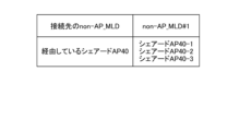
- FIG. 16 is a table showing an example of information managed by the management unit 314 of the sharing AP 30 provided in the information communication system 1A according to the second embodiment.
- the management unit 314 manages information (identifiers, etc.) related to the non-AP_MLD to which the connection is made, and information on the shared AP 40 via which the multi-AP connection is made.
- non-AP_MLD#1 is recorded as the identifier of the non-AP_MLD.
- Information (identifiers, etc.) on the shared APs 40-1, 40-2, and 40-3 is recorded as information on the shared APs 40 via which the connection is made.
- the management unit 314 can determine through which shared AP 40 subordinate to the sharing AP 30 the connection to non-AP_MLD#1 is made.
- Fig. 17 is a block diagram showing an example of the functional configuration of the shared AP 40 included in the information communication system 1A according to the second embodiment.
- the shared AP 40 includes a MAC frame processing unit 411, a transmission/reception unit 412, and a management unit 413.
- the MAC frame processing unit 411 is a functional block that executes processing corresponding to the MAC sublayer of the second layer.
- the MAC frame processing unit 411 adds a MAC header to generate a MAC frame and outputs it to the transmitting/receiving unit 412.
- the MAC frame processing unit 411 processes the MAC header of the frame input from the transmitting/receiving unit 412.
- the MAC frame processing unit 411 can also generate a MAC frame from management information such as a beacon input from the management unit 413, and output it to the transmitting/receiving unit 412 or the sharing AP 30.
- the MAC frame processing unit 411 processes the MAC header and outputs the input frame to the sharing AP 30 or the beacon control unit 421 depending on the frame type. For example, when a data frame is input from the transmitting/receiving unit 412, the MAC frame processing unit 411 outputs the input frame to the sharing AP 30. When a control frame (beacon signal) including schedule information for the R-TWT function is input from the transmitting/receiving unit 412, the MAC frame processing unit 411 outputs the input frame to the beacon control unit 421.
- a control frame (beacon signal) including schedule information for the R-TWT function
- the transceiver 412 is a functional block that executes processing corresponding to the first layer.
- the transceiver 412 generates a wireless frame by adding a preamble, etc. to the MAC frame input from the MAC frame processing unit 411, and converts the generated wireless frame into a wireless signal.
- the transceiver 412 then transmits (radiates) the converted wireless signal via an antenna.
- the transceiver 412 also extracts a MAC frame from the wireless frame received by the antenna, and outputs the extracted MAC frame to the MAC frame processing unit 411.
- the management unit 413 manages the link state and wireless communication of the transmission/reception unit 412.
- the management unit 413 may also perform processing for establishing a multi-AP connection between the sharing AP 30 and the terminal device 20.
- the management unit 413 includes, for example, a beacon control unit 421 and an R-TWT processing unit 422.
- the beacon control unit 421 generates a beacon signal and outputs it to the MAC frame processing unit 411.
- the beacon signal may include the start time (TWT start time) and duration (TWT duration) of the common R-TWT SP from the schedule information of the R-TWT SP input from the schedule control unit 211 of the sharing AP 30, and the start time (TWT start time) and duration (TWT duration) of the individual R-TWT SP to be transmitted synchronously, or may include the transmission start time of the individual data to be transmitted synchronously. If the beacon signal of the received other access point (sharing AP 30 or shared AP 40) has settings such as R-TWT SP, the beacon control unit 421 notifies the schedule control unit 211 of the sharing AP 30.
- the R-TWT processing unit 422 extracts the R-TWT SP schedule information input from the schedule control unit 211 of the sharing AP 30 that corresponds to its own channel, and outputs a trigger frame to the MAC frame processing unit 411 at the start time of that R-TWT SP.
- the trigger frame may include the duration or end time of the R-TWT SP, as well as the identifier of the target link of the next R-TWT SP, the TWT start time, and the TWT duration.
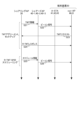
- FIG. 18 is a flowchart showing an example of a setup method of the R-TWT function in the information communication system 1A according to the second embodiment.
- Fig. 18 shows a setup sequence of the R-TWT function when a multi-AP connection using three transmission paths (shared APs 40-1, 40-2, and 40-3) is established between the sharing AP 30 and the terminal device 20.
- a setup method of the R-TWT function in the information communication system 1A according to the second embodiment will be described with reference to Fig. 18.
- the sharing AP 30 transmits TWT information to each shared AP 40 (S21).
- the TWT information includes information about links (transmission paths) that can use the TWT function.
- each shared AP 40 broadcasts a beacon signal that includes the TWT information (S22). This beacon signal can be received by each of the A-STAs #1 to #3 of the terminal device 20. When each A-STA #1 to #3 receives the beacon signal, it acquires the TWT information and transmits it to the non-AP_MLD.
- the non-AP_MLD Based on the received TWT information, the non-AP_MLD sends a TWT request to the sharing AP 30 (S23).
- the TWT request includes the identifier of the non-AP_MLD and information about the A-STA (link) available for multi-AP connection.
- the sharing AP 30 determines the target for setting up the R-TWT SP. Then, the sharing AP 30 sends an R-TWT response to the non-AP_MLD (S24).
- the R-TWT response is sent via all shared APs 40 that are targets for setting up the R-TWT SP.
- the setup of the R-TWT function (TWT agreement setup) is completed.
- the sharing AP 30 transmits schedule information to the shared AP 40 (S25).
- the schedule information includes information about the R-TWT SP set by the TWT agreement setup.
- each shared AP 40 broadcasts a beacon signal including the schedule information (S26).
- This beacon signal can be received by each of the A-STAs #1 to #3 of the terminal device 20.
- each of the A-STAs #1 to #3 receives the beacon signal, it acquires the schedule information and transmits it to the non-AP_MLD. This completes the scheduling of the R-TWT SP.
- FIG. 19 is a flowchart showing an example of a method of using the R-TWT function in the information communication system according to the second embodiment.
- a method of using the R-TWT function in the information communication system according to the second embodiment will be described with reference to Fig. 19.
- the management unit 314 of the sharing AP 30 establishes a multi-AP connection with the terminal device 20 using multiple shared APs 40, schedules at least one R-TWT SP, and then starts the series of processes shown in FIG. 19 (START).
- the schedule control unit 323 of the management unit 314 checks whether there is an R-TWT SP that does not include multiple R-TWT SPs in a single transmission path (shared AP 40) among the scheduled R-TWT SPs (S31).
- the schedule control unit 323 determines that there is an R-TWT SP that does not include multiple R-TWT SPs in a single transmission path among the scheduled R-TWT SPs. If it confirms that there is no R-TWT SP that does not include multiple R-TWT SPs, it proceeds to the process of S33 (S11: NO).
- the schedule control unit 323 sets the maximum length R-TWT SP to the common R-TWT SP, as in the first embodiment.
- the schedule control unit 323 proceeds to the process of S34.
- the schedule control unit 323 sets the period of the R-TWT SP that does not overlap with other R-TWT SPs as the common R-TWT SP, as in the first embodiment.
- the schedule control unit 323 proceeds to the process of S34.
- the management unit 314 notifies the terminal device 20 of the schedule information including the common R-TWT SP. Specifically, the schedule control unit 323 of the management unit 314 transmits the schedule information to each shared AP 40 belonging to the sharing AP 30 using the frame processing unit 312 and the transmission/reception unit 313 of each transmission path. Then, the beacon control unit 421 of the management unit 413 of each shared AP 40 generates a beacon signal including the received schedule information, and transmits (radiates) a wireless signal via the MAC frame processing unit 411 and the transmission/reception unit 412.
- the schedule control unit 323 of the management unit 314 of the sharing AP 30 performs redundant transmission of high-priority low-latency traffic using the common R-TWT SP (S35). Specifically, the schedule control unit 323 notifies the frame processing unit 312 of schedule information including the common R-TWT SP.
- the frame processing unit 312 When transmitting upstream traffic, the frame processing unit 312 outputs a trigger frame that instructs the transfer of low-latency traffic, for example, based on the common TWT start time, to each of the transceiver units 313 to which the common R-TWT SP is assigned.
- the trigger frame is transmitted to the A-STA of the terminal device 20 via the shared AP 40 associated with each transceiver unit 313 to which the common R-TWT SP is assigned. Then, each A-STA of the terminal device 20 transmits low-latency traffic to the sharing AP 30 based on the trigger frame.
- the frame processing unit 312 When transmitting downstream traffic, the frame processing unit 312 outputs downstream traffic to each of the transceiver units 313 to which a common R-TWT SP is assigned, for example, based on the common TWT start time.
- the downstream traffic is transmitted to the A-STA of the terminal device 20 via the shared AP 40 associated with each transceiver unit 313 to which a common R-TWT SP is assigned.
- low-latency traffic can be redundantly transmitted via each of the multiple transmission paths in the multi-AP connection.
- the management unit 314 of the sharing AP 30 can redundantly transmit low-latency traffic at the same timing using multiple links in the common R-TWT SP.
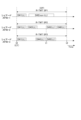
- Figure 20 is a time chart showing a specific example of communication using the R-TWT function in the information communication system according to the second embodiment.
- Figure 20 shows a processing sequence of the R-TWT function when a multi-AP connection using three transmission paths (shared APs 40-1, 40-2, and 40-3) is established between the sharing AP 30 and the terminal device 20.
- a specific example of communication using the R-TWT function in the information communication system 1A according to the second embodiment will be described with reference to Figure 20.
- R-TWT SP1 to R-TWT SP3 are set as common R-TWT SPs on three transmission paths (shared APs 40-1 to 40-3) based on a beacon signal containing schedule information for the R-TWT SPs.
- the length of each TWT duration for R-TWT SP1 to R-TWT SP3 corresponds to the common TWT duration CP.
- the common R-TWT SP is scheduled so that it does not overlap with other R-TWT SPs.
- Time t0 corresponds to the common TWT start time CT.
- each of R-TWT SP1 to R-TWT SP3 starts transmitting data D#1 corresponding to low latency traffic (LL).
- data D#1 is redundantly transmitted using shared APs 40-1 to 40-3.
- R-TWT SP1 after data D#1 is transmitted, transmission of data D#2 corresponding to non-low latency traffic (non-LL) starts.
- R-TWT SP2 after data D#1 is transmitted, data D#3 corresponding to low latency traffic (LL) is transmitted.
- R-TWT SP3 after data D#1 is transmitted, data D#4 corresponding to low latency traffic (LL) is transmitted.
- the R-TWT SP scheduled in each transmission path is scheduled to a common R-TWT SP that is a standard R-TWT SP that transmits the low-latency traffic with the highest priority.
- the sharing AP 30 uses the common R-TWT SP to redundantly transmit the low-latency traffic with the highest priority.
- the information and communications system 1A according to the second embodiment can transmit low-latency traffic through other transmission paths that are less affected by interference, even if some of the multiple transmission paths that make up the multi-AP connection are affected by interference, etc.
- the information and communications system 1A according to the second embodiment can transmit low-latency traffic more reliably, and can reduce the delay and jitter of the traffic. Therefore, the information and communications system 1A according to the second embodiment can provide an access point and a terminal device that can meet the required delay of low-latency traffic.
- the conversion process from the radio frame to the radio signal described in the above embodiment includes, for example, convolution coding, interleaving, subcarrier modulation, inverse fast Fourier transform, OFDM modulation, and frequency conversion.
- the conversion process from the radio signal to the radio frame described in the embodiment includes, for example, frequency conversion, OFDM demodulation, fast Fourier transform, subcarrier demodulation, deinterleaving, and Viterbi decoding.
- the CPU 11 of the access point 10, the CPU 21 of the terminal device 20, the CPU of the sharing AP 30, and the CPU of the shared AP 40 may each be other circuits.
- the access point 10, the terminal device 20, the sharing AP 30, and the shared AP 40 may each be equipped with an MPU (Micro Processing Unit) or the like instead of a CPU.
- MPU Micro Processing Unit
- Each of the processes described in each embodiment may be realized by dedicated hardware.
- the processes of the access point 10, the terminal device 20, the sharing AP 30, and the shared AP 40 may be a mixture of processes executed by software and processes executed by hardware, or may be only one of them.
- the flow chart used to explain the operations is merely an example.
- the order of the operations explained in the embodiment may be changed to the extent possible, and other processes may be added.
- the multi-link or multi-AP connection setup method and R-TWT communication method explained in the above embodiment are merely an example.
- a wireless communication standard other than the IEEE 802.11 standard may be used as the wireless communication standard.
- the present invention is not limited to the above-described embodiments, and can be modified in various ways during implementation without departing from the gist of the invention.
- the embodiments may also be implemented in appropriate combination, in which case the combined effects can be obtained.
- the above-described embodiments include various inventions, and various inventions can be extracted by combinations selected from the multiple constituent elements disclosed. For example, if the problem can be solved and an effect can be obtained even if some constituent elements are deleted from all the constituent elements shown in the embodiments, the configuration from which these constituent elements are deleted can be extracted as an invention.
Landscapes
- Engineering & Computer Science (AREA)
- Computer Networks & Wireless Communication (AREA)
- Signal Processing (AREA)
- Mobile Radio Communication Systems (AREA)
Priority Applications (2)
| Application Number | Priority Date | Filing Date | Title |
|---|---|---|---|
| JP2025551287A JPWO2025079211A1 (cg-RX-API-DMAC7.html) | 2023-10-12 | 2023-10-12 | |
| PCT/JP2023/037066 WO2025079211A1 (ja) | 2023-10-12 | 2023-10-12 | アクセスポイント及び端末装置 |
Applications Claiming Priority (1)
| Application Number | Priority Date | Filing Date | Title |
|---|---|---|---|
| PCT/JP2023/037066 WO2025079211A1 (ja) | 2023-10-12 | 2023-10-12 | アクセスポイント及び端末装置 |
Publications (1)
| Publication Number | Publication Date |
|---|---|
| WO2025079211A1 true WO2025079211A1 (ja) | 2025-04-17 |
Family
ID=95395510
Family Applications (1)
| Application Number | Title | Priority Date | Filing Date |
|---|---|---|---|
| PCT/JP2023/037066 Ceased WO2025079211A1 (ja) | 2023-10-12 | 2023-10-12 | アクセスポイント及び端末装置 |
Country Status (2)
| Country | Link |
|---|---|
| JP (1) | JPWO2025079211A1 (cg-RX-API-DMAC7.html) |
| WO (1) | WO2025079211A1 (cg-RX-API-DMAC7.html) |
Citations (2)
| Publication number | Priority date | Publication date | Assignee | Title |
|---|---|---|---|---|
| JP2022074532A (ja) * | 2020-11-04 | 2022-05-18 | キヤノン株式会社 | 通信装置、制御方法、およびプログラム |
| WO2023162212A1 (ja) * | 2022-02-28 | 2023-08-31 | 日本電信電話株式会社 | 基地局及び無線端末装置 |
-
2023
- 2023-10-12 JP JP2025551287A patent/JPWO2025079211A1/ja active Pending
- 2023-10-12 WO PCT/JP2023/037066 patent/WO2025079211A1/ja not_active Ceased
Patent Citations (2)
| Publication number | Priority date | Publication date | Assignee | Title |
|---|---|---|---|---|
| JP2022074532A (ja) * | 2020-11-04 | 2022-05-18 | キヤノン株式会社 | 通信装置、制御方法、およびプログラム |
| WO2023162212A1 (ja) * | 2022-02-28 | 2023-08-31 | 日本電信電話株式会社 | 基地局及び無線端末装置 |
Also Published As
| Publication number | Publication date |
|---|---|
| JPWO2025079211A1 (cg-RX-API-DMAC7.html) | 2025-04-17 |
Similar Documents
| Publication | Publication Date | Title |
|---|---|---|
| JP7074624B2 (ja) | Wlanにおけるofdmaリソース管理のためのシステム及び方法 | |
| EP2995152B1 (en) | Systems and methods for operation of wireless user devices with cellular and wi-fi interfaces | |
| TW201130358A (en) | Apparatus and methods for multi-radio coordination of heterogeneous wireless networks | |
| JP7768338B2 (ja) | 基地局及び無線端末装置 | |
| US20250193953A1 (en) | Base station and wireless terminal apparatus | |
| WO2023134517A1 (zh) | 无线局域网中的时间资源调度方法、装置及可读存储介质 | |
| CN100505584C (zh) | 快速预约列发多址接入方法 | |
| JP2026048834A (ja) | アクセスポイント及び端末 | |
| EP3410750B1 (en) | Wireless communication system, wireless station, and wireless communication method | |
| US20250386280A1 (en) | Access point, data receiving method and data receiving program | |
| WO2025079208A1 (ja) | アクセスポイント及び端末装置 | |
| CN112586030B (zh) | 一种系统信息块sib传输方法及设备 | |
| CN121359564A (zh) | 使用特定于流的资源预留经由多跳中继路径的背靠背发送 | |
| WO2024034051A1 (ja) | アクセスポイント、無線端末装置、及び通信システム | |
| WO2024009452A1 (ja) | 無線装置及び無線通信方法 | |
| EP4723795A1 (en) | Sharing access point, shared access point, and terminal device | |
| US20260082422A1 (en) | Mechanisms for transmission opportunity preemption | |
| US20250274999A1 (en) | Massively coordinated access point (ap) service periods and service intervals | |
| WO2024214276A1 (ja) | アクセスポイント及び端末 | |
| WO2024214275A1 (ja) | アクセスポイント及び端末 | |
| WO2025238720A1 (ja) | 制御装置 | |
| WO2024257280A1 (ja) | シェアリングアクセスポイント、シェアードアクセスポイント及び端末 | |
| WO2026007916A1 (zh) | 无线通信方法、第一ap以及第一sta | |
| WO2025238730A1 (ja) | アクセスポイント及び端末装置 | |
| TW202602157A (zh) | 基於控制器的網路中的用於多中繼段流量流的基於協調排程的協定 |
Legal Events
| Date | Code | Title | Description |
|---|---|---|---|
| 121 | Ep: the epo has been informed by wipo that ep was designated in this application |
Ref document number: 23955459 Country of ref document: EP Kind code of ref document: A1 |
|
| ENP | Entry into the national phase |
Ref document number: 2025551287 Country of ref document: JP Kind code of ref document: A |
|
| WWE | Wipo information: entry into national phase |
Ref document number: 2025551287 Country of ref document: JP |
|
| NENP | Non-entry into the national phase |
Ref country code: DE |