WO2025075136A1 - 音声信号処理方法、コンピュータプログラム、及び、音声信号処理装置 - Google Patents
音声信号処理方法、コンピュータプログラム、及び、音声信号処理装置 Download PDFInfo
- Publication number
- WO2025075136A1 WO2025075136A1 PCT/JP2024/035590 JP2024035590W WO2025075136A1 WO 2025075136 A1 WO2025075136 A1 WO 2025075136A1 JP 2024035590 W JP2024035590 W JP 2024035590W WO 2025075136 A1 WO2025075136 A1 WO 2025075136A1
- Authority
- WO
- WIPO (PCT)
- Prior art keywords
- sound
- audio signal
- threshold
- reflected
- information
- Prior art date
- Legal status (The legal status is an assumption and is not a legal conclusion. Google has not performed a legal analysis and makes no representation as to the accuracy of the status listed.)
- Pending
Links
Images





















Classifications
-
- H—ELECTRICITY
- H04—ELECTRIC COMMUNICATION TECHNIQUE
- H04S—STEREOPHONIC SYSTEMS
- H04S7/00—Indicating arrangements; Control arrangements, e.g. balance control
Definitions
- the audio signal processing method is an audio signal processing method executed by an audio signal processing device, and includes an acquisition step of acquiring an audio signal including attribute information that identifies an attribute of the audio signal, a determination step of performing a first determination process of determining whether the acquired audio signal satisfies a first condition and a second determination process of determining whether the acquired audio signal satisfies a second condition different from the first condition when the attribute identified by the attribute information included in the acquired audio signal is information indicating indirect sound, and a reproduction step of outputting an output signal based on the acquired audio signal when the acquired audio signal satisfies the first condition and the second condition.
- An audio signal processing device includes an acquisition unit that acquires an audio signal including attribute information that identifies an attribute of the audio signal, a determination unit that performs a first determination process that determines whether the acquired audio signal satisfies a first condition and a second determination process that determines whether the acquired audio signal satisfies a second condition different from the first condition when the attribute identified by the attribute information included in the acquired audio signal is information indicating indirect sound, and a playback unit that outputs an output signal based on the acquired audio signal when the acquired audio signal satisfies the first condition and the second condition.
- FIG. 22 is a diagram showing an example of the arrangement of avatars, sound source objects, and obstacle objects.
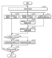
- FIG. 23 is a flowchart showing yet another example of the selection process.
- FIG. 24 is a block diagram showing an example of a configuration for a rendering unit to perform pipeline processing.
- FIG. 25 is a diagram showing sound transmission and diffraction.
- FIG. 26 is a block diagram illustrating an example of a configuration of a rendering unit according to the second embodiment.
- FIG. 27 is a flowchart showing an example of the operation of the audio signal processing device according to the second embodiment.
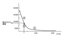
- FIG. 28 is a graph showing threshold data indicating the first threshold value according to the second embodiment.
- FIG. 29 is a block diagram illustrating an example of a configuration of a rendering unit according to the third embodiment.
- appropriately selecting and outputting (playing back) one or more reflected sounds that are to be processed or not to be processed from among the multiple reflected sounds that occur in the sound space during playback is useful for appropriately reducing the amount of calculation and the calculation load.
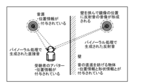
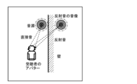
- Patent Document 1 the importance of an audio signal, more specifically, the importance of the direct sound indicated by the audio signal is detected, but the importance of reflected sound is not considered. For this reason, when indirect sound such as reflected sound occurs as shown in Figure 1, the amount of calculation and the calculation load increase, which means that it may be difficult to appropriately reduce the amount of calculation and the calculation load.
- the audio signal processing method is an audio signal processing method executed by an audio signal processing device, and includes an acquisition step of acquiring an audio signal including attribute information that identifies an attribute of the audio signal, a determination step of performing a first determination process of determining whether the acquired audio signal satisfies a first condition and a second determination process of determining whether the acquired audio signal satisfies a second condition different from the first condition when the attribute identified by the attribute information included in the acquired audio signal is information indicating indirect sound, and a reproduction step of outputting an output signal based on the acquired audio signal when the acquired audio signal satisfies the first condition and the second condition.
- the audio signal processing method according to the fourth aspect of the present disclosure is the audio signal processing method according to the third aspect, in which the predetermined sound is a direct sound.
- the first judgment process has an extremely light computational load, since it is mainly a process of judging the magnitude relationship between the amplitude value of the target audio signal and a predetermined threshold.
- the second judgment process requires calculation of the volume ratio and arrival time difference between the target indirect sound and the direct sound related to the indirect sound, and therefore has a much larger computational load than the first judgment process. Therefore, in the first judgment process, which has a light computational load, multiple input signals are first sieved, and only the remaining signals are judged in the second judgment process. In this way, the amount of calculation for the entire judgment step can be significantly reduced, so this order of processing is extremely important in the present disclosure, whose original purpose is to reduce the amount of calculation for audio signal processing.
- the audio signal processing device 1001 performs acoustic processing based on spatial information that describes the factors that cause the above-mentioned effects.
- the spatial information includes, for example, information indicating the positions of the sound source, the listener, and surrounding objects, information indicating the shape of the space, and parameters related to sound propagation.
- the audio signal processing device 1001 is, for example, a PC (Personal Computer), a smartphone, a tablet, or a game console.
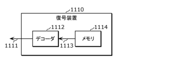
- the audio signal processing device 1001 may also decode a bit stream generated by encoding at least a portion of the data of the audio signal and the spatial information used in the audio processing, and perform the audio processing. Therefore, the audio signal processing device 1001 may be referred to as a decoding device.
- the encoding device 1100 stores encoded data 1103 in a memory 1104.
- the encoding device 1120 differs from the encoding device 1100 in that it includes a transmission unit 1121 that transmits the encoded data 1103 to the outside.
- the decryption device 1110 reads the input data 1113 from the memory 1114.
- the decryption device 1130 differs from the decryption device 1110 in that it includes a receiving unit 1131 that receives the input data 1113 from outside.
- the receiving unit 1131 receives the received signal 1132, acquires the received data, and outputs the input data 1113 that is input to the decoder 1112.
- the received data may be the same as the input data 1113 that is input to the decoder 1112, or may be data in a different data format from the input data 1113.
- the input data 1113 is an encoded bitstream and includes encoded audio data, which is an encoded audio signal, and metadata used in the acoustic processing.
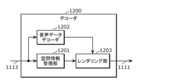
- the spatial information management unit 1201 acquires metadata contained in the input data 1113 and analyzes the metadata.
- the metadata includes information describing elements that act on sounds arranged in a sound space.
- the spatial information management unit 1201 manages the spatial information used for acoustic processing obtained by analyzing the metadata, and provides the spatial information to the rendering unit 1203.
- the information used in the acoustic processing is expressed as spatial information
- other expressions may be used.
- the information used in the acoustic processing may be expressed as sound spatial information or as scene information.
- the spatial information input to the rendering unit 1203 may be information expressed as a spatial state, a sound spatial state, a scene state, or the like.
- the information managed by the spatial information management unit 1201 is not limited to information contained in the bitstream.
- the input data 1113 may include data that is not included in the bitstream, and that indicates the characteristics and structure of the space obtained from software or a server that provides VR or AR.
- the audio data decoder 1202 decodes the encoded audio data contained in the input data 1113 to obtain an audio signal.
- the encoding method may be a lossy codec such as MP3 (MPEG-1 Audio Layer-3), AAC (Advanced Audio Coding), WMA (Windows Media Audio), AC3 (Audio Codec-3) or Vorbis.
- the encoding method may be a lossless codec such as ALAC (Apple Lossless Audio Codec) or FLAC (Free Lossless Audio Codec).
- PCM data may be a type of encoded audio data.
- the decoding process may be, for example, a process of converting an N-bit binary number into a number format (e.g., floating-point format) that can be processed by the rendering unit 1203, where the number of quantization bits of the PCM data is N.
- FIG. 4B differs from FIG. 4A in that the input data 1113 includes an unencoded audio signal rather than encoded audio data.
- the input data 1113 includes a bitstream including metadata and an audio signal.
- the spatial information management unit 1211 is the same as the spatial information management unit 1201 in FIG. 4A, so a description thereof will be omitted.
- decoders 1112, 1200, and 1210 may be expressed as audio processing units that perform audio processing.
- the decoding devices 1110 and 1130 may be the audio signal processing device 1001, and may be expressed as audio processing devices.
- the communication IF 1403 is a communication module compatible with a communication method such as Bluetooth (registered trademark) or WIGIG (registered trademark).
- the audio signal processing device 1001 communicates with another communication device via the communication IF 1403, for example, to obtain a bitstream to be decoded.
- the obtained bitstream is stored in the memory 1404, for example.
- Sensor 1405 performs sensing to estimate the position and orientation of the listener. Specifically, sensor 1405 estimates the position and/or orientation of the listener based on one or more detection results of the position, orientation, movement, velocity, angular velocity, acceleration, etc. of a part or the whole of the body, and generates position/or orientation information indicating the position and/or orientation of the listener.
- the sensor 1405 is, for example, an imaging device such as a camera or a ranging device such as a LiDAR (Laser Imaging Detection and Ranging).
- the sensor 1405 may capture the movement of the listener's head and detect the movement of the listener's head by processing the captured image.
- a device that performs position estimation using wireless signals of any frequency band, such as millimeter waves, may be used as the sensor 1405.
- Speaker 1401 has, for example, a diaphragm, a drive mechanism such as a magnet or voice coil, and an amplifier, and presents the audio signal after acoustic processing as sound to the listener. Speaker 1401 operates the drive mechanism in response to the audio signal (more specifically, a waveform signal indicating the waveform of the sound) amplified via the amplifier, and causes the drive mechanism to vibrate the diaphragm. In this way, the diaphragm vibrating in response to the audio signal generates sound waves, which propagate through the air and are transmitted to the listener's ears, causing the listener to perceive the sound.
- the audio signal more specifically, a waveform signal indicating the waveform of the sound
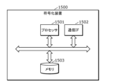
- the processor 1501 is, for example, a CPU, a DSP, or a GPU.
- the CPU, DSP, or GPU may execute a program stored in the memory 1503 to perform the encoding process of the present disclosure.
- the processor 1501 is, for example, a circuit that performs information processing.
- the processor 1501 may be a dedicated circuit that performs signal processing on an audio signal, including the encoding process of the present disclosure.
- Memory 1503 is composed of, for example, RAM or ROM.
- Memory 1503 may include a magnetic recording medium such as a hard disk or a semiconductor memory such as an SSD.
- Memory 1503 may also be an internal memory built into the CPU or GPU.
- FIG. 7 is a block diagram showing an example of the configuration of the rendering unit 1300. Specifically, Fig. 7 shows an example of the detailed configuration of the rendering unit 1300, which corresponds to the rendering units 1203 and 1213 in Fig. 4A and Fig. 4B.
- the input signal is composed of, for example, spatial information, sensor information, and sound data.
- the input signal may include a bitstream composed of sound data and metadata (control information), in which case the metadata may include spatial information.
- Spatial information is information about the sound space (three-dimensional sound field) created by the stereophonic sound reproduction system 1000, and is composed of information about the objects contained in the sound space and information about the listener.
- Objects include sound source objects that emit sound and are sound sources, and non-sound-emitting objects that do not emit sound. Sound source objects can also be simply expressed as sound sources.
- the position information is expressed by coordinate values on three axes, for example the X-axis, Y-axis, and Z-axis, in Euclidean space, but it does not necessarily have to be three-dimensional information.
- the position information may be two-dimensional information expressed by coordinate values on two axes, the X-axis and the Y-axis.
- the position information of an object is determined by the representative position of a shape expressed by a mesh or voxels.
- the attenuation rate may be expressed as a real number between 0 and 1, or may be expressed as a negative decibel value.
- sound volume is not amplified by reflection, so the attenuation rate is set to a negative decibel value, but for example, to create the eerie feeling of an unreal space, an attenuation rate of 1 or greater, i.e., a positive decibel value, may be set.
- the spatial information may also include information indicating whether the object belongs to a living organism, and information indicating whether the object is a moving object. If the object is a moving object, the position indicated by the position information may move over time. In this case, information on the changed position or the amount of change is transmitted to the rendering unit 1300.
- Information about a sound source object includes information commonly assigned to sound source objects and non-sound generating objects, as well as sound data and information necessary to radiate the sound data into a sound space.
- the sound data is data that indicates information about the frequency and strength of a sound, and is data that expresses the sound perceived by a listener.
- the reflected sound according to this embodiment is an example of an indirect sound.
- the indirect sound may be a reflected sound, a diffracted sound, or the like.
- the direct sound according to this embodiment is an example of a predetermined sound that is different from the indirect sound.
- the predetermined sound may be a direct sound or a high order ambisonics sound (HOA: High Order Ambisonics).
- HOA High Order Ambisonics
- a representative sound of the multiple sounds represented by the multiple audio signals may be created by bundling the multiple audio signals (by mixing, etc.), and the representative sound may be used as the predetermined sound. In this case, the representative sound may be called a representative sound.
- reflected sound which is an example of indirect sound
- direct sound which is an example of predetermined sound
- orientation information is typically expressed using yaw, pitch, and roll.
- the roll rotation may be omitted, and the orientation information of the sound source object may be expressed using azimuth (yaw) and elevation (pitch).
- the orientation information of the sound source object may change over time, and if it does change, it is transmitted to the rendering unit 1300.
- the sensor information includes the amount of rotation or displacement detected by the sensor 1405 worn by the listener, and the listener's position and orientation.
- the sensor information is transmitted to the rendering unit 1300, which updates the listener's position and orientation information based on the sensor information.
- the sensor information may include position information obtained by the mobile terminal performing self-position estimation using a GPS, a camera, LiDAR, or the like, for example.
- the analysis unit 1301 analyzes the audio signal contained in the input signal and the spatial information received from the spatial information management units 1201 and 1211, and calculates the information necessary for the generation of direct sound and reflected sound in the reproduction unit 1303, as well as the information necessary for determining (selecting) whether or not to generate reflected sound.
- Information required to generate direct sound and reflected sound is, for example, values related to the path taken by the direct sound and reflected sound to reach the listening position, the time it takes to reach the listening position, and the volume at the time of arrival, for each sound.
- the values related to the path taken by the direct sound and reflected sound to reach the listening position, the time it takes to reach the listening position, and the volume at the time of arrival are, for example, values indicating the path taken by the direct sound and reflected sound to reach the listening position, the time it takes to reach the listening position, and the volume at the time of arrival, for each sound.
- the information required to select the reflected sound to be output is information indicating the relationship between the direct sound and the reflected sound, such as a value relating to the time difference between the direct sound and the reflected sound, and a value relating to the volume ratio between the direct sound and the reflected sound at the listening position.
- the value relating to the time difference between the direct sound and the reflected sound, and the value relating to the volume ratio between the direct sound and the reflected sound at the listening position are, for example, a value indicating the time difference between the direct sound and the reflected sound, and a value indicating the volume ratio between the direct sound and the reflected sound at the listening position, respectively.
- volume ratio typically refers to the gain difference when the volumes of two sounds are expressed in decibel units
- the threshold data is also typically defined as a gain difference expressed in the decibel domain.
- the volume ratio is not limited to a gain difference in the decibel domain.
- the threshold data defined in the decibel domain may be converted into the unit of the calculated volume ratio and used.
- the threshold data defined in each unit may be stored in advance in memory.
- the analysis unit 1301 analyzes the input signal input to the audio signal processing device 1001 to detect direct sound and reflected sound that may occur in the sound space.
- the reflected sound detected here is a candidate for the reflected sound that is ultimately selected by the determination unit 1302 as the reflected sound to be generated by the reproduction unit 1303.
- the analysis unit 1301 also analyzes the input signal to calculate information necessary for generating direct sound and reflected sound, and information necessary for selecting the reflected sound to be generated.
- the characteristics of the direct sound and the reflected sound are calculated. Specifically, the arrival time and volume of the direct sound and the reflected sound when they reach the listener are calculated. If multiple objects exist in the sound space as reflecting objects, the characteristics of the reflected sound are calculated for each of the multiple objects.
- the direct sound arrival time (td) is calculated based on the direct sound arrival path (pd).
- the direct sound arrival path (pd) is the path connecting the position information S (xs, ys, zs) of the sound source object and the position information A1 (xa, ya, za) of the listener.
- the direct sound arrival time (td) is a value obtained by dividing the length of the path connecting the position information S (xs, ys, zs) and the position information A1 (xa, ya, za) by the speed of sound (approximately 340 m/sec).
- the path length (X) is calculated as (xs-xa) ⁇ 2 + (ys-ya) ⁇ 2 + (zs-za) ⁇ 2) ⁇ 0.5.
- the volume N at the sound source position may be the reference volume described above.
- the attenuation rate G may be expressed as a real number between 0 and 1, or may be expressed as a negative decibel value.
- the volume of the entire signal is attenuated by G.
- the attenuation rate may also be set for each frequency band that constitutes multiple frequency bands.
- the analysis unit 1301 multiplies each frequency component of the signal by a specified attenuation rate.
- the analysis unit 1301 may also use a representative value or average value of multiple attenuation rates for multiple frequency bands as the overall attenuation rate, and attenuate the volume of the entire signal by that amount.
- the determination unit 1302 may select reflected sounds to which other processes are to be applied, not limited to generation processes. For example, the determination unit 1302 may select reflected sounds to which binaural processing is to be applied. Furthermore, the determination unit 1302 basically selects only one or more reflected sounds to be processed. However, the determination unit 1302 may select only one or more reflected sounds that are not to be processed. Then, processing may be applied to the one or more reflected sounds that are not selected.
- the selection of whether or not to generate reflected sound is made by, for example, comparing the volume ratio between direct sound and reflected sound, which corresponds to the time difference between the direct sound and the reflected sound, with a preset threshold.
- the threshold is set by referring to threshold data.
- the threshold data is an index that indicates the boundary between whether or not a reflected sound relative to a direct sound is perceived by a listener, and is defined as the ratio between the volume when the direct sound arrives (Id) and the volume when the reflected sound arrives (lr).
- the threshold corresponds to a value expressed by a numerical value or the like that is determined in response to the time difference (T).
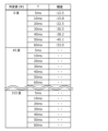
- the threshold data corresponds to the relationship between the time difference (T) and the threshold, and corresponds to table data or a relational expression that is used to identify or calculate the threshold at the time difference (T).
- the format and type of the threshold data are not limited to table data or a relational expression.
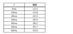
- FIG. 11 is a diagram showing the relationship between the time difference between direct sound and reflected sound and a threshold value.
- threshold data of a volume ratio that is predetermined for each value of the time difference between direct sound and reflected sound as shown in FIG. 11 may be referenced.
- threshold data obtained by interpolation or extrapolation from the threshold data shown in FIG. 11 may be referenced.
- threshold data for the volume ratio that is predetermined for each value of the time difference between the direct sound and the reflected sound By performing selection processing using threshold data for the volume ratio that is predetermined for each value of the time difference between the direct sound and the reflected sound, it is possible to realize selection processing that takes post-masking or the precedence effect into consideration. A detailed explanation of the type, format, storage method, and setting method of the threshold data will be given later.
- the volume (lr) at the time of arrival of the reflected sound when generating the reflected sound is different from the volume at the time of arrival of the direct sound, and is a value to which the attenuation rate G of the volume at the reflection is applied.
- G may be an attenuation rate that is applied to all frequency bands at once.
- a reflectance rate may be specified for each specified frequency band in order to reflect the bias of frequency components caused by reflection.
- the process of applying the volume (lr) at the time of arrival of the reflected sound may be implemented as a frequency equalizer process that multiplies each band by an attenuation rate.
- the path length of the direct sound and the reflected sound candidates as they arrive at the listener is calculated. Furthermore, the arrival time and volume at the time of arrival are calculated based on each path length. Then, the reflected sound candidate selection process is performed based on the time difference and volume ratio.
- the selection process may be performed based on the path length of the direct sound and the reflected sound when they reach the listener, and the calculation of the arrival time and volume of the direct sound and the reflected sound, as well as the calculation of the time difference and volume ratio may be omitted.
- a threshold value according to the path length difference may be predefined for the path length ratio. Then, the selection process may be performed based on whether the calculated path length ratio is equal to or greater than the threshold value according to the calculated path length difference. This makes it possible to perform the selection process based on the path length difference corresponding to the time difference while reducing the amount of calculations.
- the threshold data may be determined based on the minimum time difference at which the listener's perception can detect a discrepancy between two sounds due to the auditory nerve function or the cognitive function in the brain, more specifically, due to the precedence effect described below, the temporal masking phenomenon described below, or a combination of these. Specific numerical values may be derived from already known research results on the temporal masking effect, the precedence effect, or the echo detection limit, or may be determined by listening experiments that are premised on application to the virtual space.
- the volume information of the sound source may indicate a reference volume defined for each content, a temporal transition of the volume, or both.
- the volume transitions intermittently over a short period of time. In other words, sound and silence alternate. If the virtual space is a concert hall and the direct sound is a musical performance, the volume is maintained for a certain length of time. If the virtual space is a battlefield and the direct sound is an explosion, the volume increases for a moment and then remains silent or low.
- the selection process and the evaluation process may be executed independently, or only one of them may be executed. Furthermore, the evaluation process may be executed only for the reflected sounds that are determined to be selected in the selection process, and the evaluation process may re-determine whether or not to select the reflected sounds. Alternatively, the evaluation process may be executed only for the reflected sounds that are determined not to be selected in the selection process, and the evaluation process may re-determine whether or not to select the reflected sounds.
- the above-described selection process can be interpreted as a process of selecting a reflected sound according to the properties of the direct sound.
- a threshold value used to select a reflected sound is set or adjusted according to the properties of the direct sound.
- an evaluation value used to select a reflected sound is calculated based on one or more of the volume of the sound source, the visibility of the sound source, the positioning of the sound source, the visibility of a reflecting object (obstacle object), and the geometric relationship between the direct sound and the reflected sound.
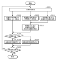
- FIG. 14 is a flowchart showing an example of the selection process.
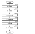
- the determination unit 1302 specifies the reflected sound detected by the analysis unit 1301 (S201). Then, the determination unit 1302 detects the volume ratio (L) between the direct sound and the reflected sound, and the time difference (T) between the direct sound and the reflected sound (S202 and S203).
- the determination unit 1302 also uses the threshold data to identify a threshold value corresponding to the time difference (T) (S204). Then, the determination unit 1302 determines whether the detected volume ratio (L) is equal to or greater than the threshold value (S205).
- the determination unit 1302 selects the reflected sound as the reflected sound to be generated (S206). If the volume ratio (L) is smaller than the threshold (No in S205), the determination unit 1302 does not select the reflected sound as the reflected sound to be generated (S207). That is, in this case, the determination unit 1302 determines the reflected sound as a reflected sound not to be generated.
- the determination unit 1302 determines whether or not there is an unspecified reflected sound (S208). If there is an unspecified reflected sound (Yes in S208), the determination unit 1302 repeats the above-mentioned processing (S201 to S207). If there is no unspecified reflected sound (No in S208), the determination unit 1302 ends the processing.
- threshold data in multiple formats and multiple types may be stored in combination.
- the combined threshold data may be read from the spatial information management units 1201 and 1211, and a threshold to be used in the selection process may be set.
- the threshold data stored in memory 1404 may be stored in the spatial information management units 1201 and 1211.
- the memory 1404 may store information regarding a relational equation showing the relationship between the time difference (T) and the threshold value.
- a relational equation showing the relationship between the time difference (T) and the threshold value.
- an equation having the time difference (T) as a variable may be stored.
- the threshold value of each time difference (T) may be approximated by a straight line or a curve, and parameters indicating the geometric shape of the line or curve may be stored. For example, if the geometric shape is a straight line, the starting point and the slope for expressing the straight line may be stored.
- threshold data may be stored for each time difference (T).
- the information about the threshold has a time item as a one-dimensional index.
- the information about the threshold may also have a two-dimensional or three-dimensional index that further includes a variable related to the direction of arrival.
- the thresholds are stored in an array that has the direction of the direct sound ( ⁇ ) (more specifically, the angle ( ⁇ ) of the direction from which the direct sound arrives) and the direction of the reflected sound ( ⁇ ) (more specifically, the angle ( ⁇ ) of the direction from which the reflected sound arrives) as independent variables or indexes.
- the angle ( ⁇ ) of the direction from which the direct sound arrives and the angle ( ⁇ ) of the direction from which the reflected sound arrives do not have to be used as independent variables.
- the information indicating the characteristics of the audio signal may be obtained before the rendering process begins, or may be obtained each time the rendering process is performed.
- the threshold adjustment unit 1304 does not have to be included in the audio signal processing device 1001, and another communication device may have the role of the threshold adjustment unit 1304.
- the analysis unit 1301 or the determination unit 1302 may acquire information indicating the nature of the audio signal, threshold data according to the nature, or information for adjusting the threshold data according to the nature from the other communication device via the communication IF 1403.
- information indicating the characteristics of the audio signal, information for adjusting the threshold, or both may be transmitted in an input signal other than the input signal containing the audio signal.
- the input signal containing the audio signal may contain information associating the other input signal with the input signal, or the information associating the other input signal with the input signal may be stored in memory 1404 together with information regarding the threshold.
- the threshold used to select the reflected sound is set according to the properties of the direct sound, i.e., the properties of the audio signal.
- threshold data set in advance for each property may be used, or as in Figure 19, the threshold may be adjusted according to the properties of the audio signal.
- the parameters of the threshold data may be adjusted according to the properties of the audio signal.
- Non-Patent Document 1 Two short sounds that arrive at the listener's ears in succession will be heard as one sound if the time interval between them is short enough. This phenomenon is called the precedence effect. It is known that the precedence effect occurs only for discontinuous, i.e., transient, sounds (Non-Patent Document 1). Therefore, when the audio signal represents a stationary sound, the echo detection limit may be set lower than when the audio signal represents a non-stationary sound.
- parameters for setting the threshold data according to information indicating the continuity of the direct sound may be stored in advance in the memory 1404.
- the threshold adjustment unit 1304 may determine the continuity of the audio signal, and set the threshold data used to select the reflected sound based on the information and parameters indicating the continuity.
- a short threshold is set. Also, the shorter the duration of the direct sound, the shorter the threshold is set.
- the threshold may be set lower when the direct sound is an intermittent sound (such as speech) than when the direct sound is a continuous sound (such as music).
- the threshold may be set higher for music, etc. than for speech, etc. Conversely, the threshold may be set lower for speech, etc. than for music, etc. In other words, if the direct sound has many intermittent parts, the threshold may be set lower.
- the information indicating the characteristics of the direct sound may be information indicating the continuity, intermittency, duration, etc. of the direct sound. Furthermore, the information indicating the characteristics of the direct sound may be any combination of these. Furthermore, the information indicating the characteristics of the direct sound may be information indicating the time variation of any of these, or information indicating the time variation of any combination of these. In other words, the information indicating the characteristics of the direct sound may be information indicating the time variation of the direct sound.
- the volume of the reflected sound is obtained by geometric calculation from information on the positions of the sound source, the listener, and the reflecting object. Specifically, the reference volume of the reflected sound relative to the reference volume of the sound source is obtained. By increasing or decreasing the reference volume of the reflected sound using information on the transition of the sound source's loudness as information indicating the properties of the direct sound, it is possible to accurately determine the volume of the reflected sound from moment to moment. The reason for this is that fluctuations in the volume of the sound source are reflected in fluctuations in the volume of the reflected sound.
- the same result can be obtained by not adjusting the reference volume of the reflected sound, but instead adjusting the threshold based on the inverse of the information on the loudness transition of the sound source, and comparing the adjusted threshold with the reference volume of the reflected sound.
- the reference volume of the reflected sound may be adjusted using the information on the loudness transition of the sound source, or the threshold may be adjusted using the information on the loudness transition of the sound source. Adjustment of the reference volume of the reflected sound and adjustment of the threshold correspond to each other.
- the sound reflectance (the rate attenuation of sound due to reflection) varies for each frequency band depending on the composition of the surface of the object that reflects the sound. Therefore, as described below, a sound reflectance (attenuation rate) may be associated with each frequency band for each object that reflects sound. Using such reflectance information and spectrogram information, it is possible to more accurately determine whether or not to select the reflected sound. For example, the following process is performed.
- the information indicating the time variation of the direct sound may be information obtained by calculating the energy or average amplitude of the direct sound for each predetermined short time length (for example, 5 ms; hereafter, frames of this time length will be referred to as analysis frames).
- the information indicating the time variation of the direct sound may be information represented as a weighted average of the energy or average amplitude calculated in the past N-1 analysis frames.
- the energy of the nth analysis frame is expressed as E(n)
- the information indicating the properties of the direct sound I(n) can be calculated according to the following formula:
- the parameter a(i) represents a weighting coefficient.
- a(i) is set so that a(i) ⁇ 0 and the sum of a(i) is 1.
- the method for setting a(i) is not limited to this.
- information I(n) indicating the properties of the direct sound is calculated every 5 ms that the direct sound is captured. In other words, it is possible to calculate the time variation of information I(n) indicating the properties of the direct sound with low latency. Therefore, this method is suitable for application in applications that require real-time performance.
- formulas 1 and 2 can be considered as filters in which E(n) is the input signal and I(n) is the output signal.
- formula 1 is a moving average (MA) model filter
- formula 2 is an autoregressive (AR) model filter, both of which have the characteristics of a low-pass filter.
- AR autoregressive
- ARMA model filter that combines both may be used.
- the method of deriving the information indicating the time variation of the direct sound is not limited to the above-mentioned formula or filter, and other known methods may be used.
- the information indicating the time variation of the direct sound indicates a value obtained by analyzing the direct sound for a predetermined time length.
- the direct sound may be analyzed from a perspective other than the average energy.
- the information indicating the properties of the direct sound may be information related to the frequency characteristics of the direct sound.
- the information related to the frequency characteristics of the direct sound may be information calculated using the frequency characteristics of the direct sound.
- the information related to the frequency characteristics of the direct sound may be information obtained as the average energy of the low-frequency components by averaging the low-frequency components of the direct sound over a predetermined analysis length.
- the energy of the low-frequency components in the nth analysis frame is expressed as EL(n)
- the information I(n) indicating the properties of the direct sound can be calculated according to the following formula:
- parameter c(i) represents a weighting coefficient.
- c(i) is set so that c(i) ⁇ 0 and the sum of c(i) is 1.
- the method for setting c(i) is not limited to this.
- information I(n) indicating the properties of the direct sound is calculated every 5 ms that the direct sound is captured. In other words, it is possible to calculate the time variation of information I(n) indicating the properties of the direct sound with low latency. Therefore, this method is suitable for application in applications that require real-time performance.
- Equation 2 information I(n) indicating the properties of the direct sound may be obtained according to the following equation:
- the parameter d(i) represents a weighting coefficient.
- d(i) is set so that d(i) ⁇ 0 and the sum of d(i) is 1.
- the method of setting d(i) is not limited to this.
- formulas 3 and 4 can be considered as filters in which E(n) is the input signal and I(n) is the output signal.
- formula 3 is a moving average (MA) model filter
- formula 4 is an autoregressive (AR) model filter, both of which have the characteristics of a low-pass filter.
- AR autoregressive
- ARMA model filter that combines both may be used.
- a filter with low-pass characteristics is used to determine the low-frequency components of the direct sound, but the method of determining the low-frequency components of the direct sound is not limited to this. Furthermore, the method of deriving information indicating the time variation of the direct sound is not limited to the above-mentioned formula or filter, and other known methods may be used.
- the spectrum of the direct sound may be calculated by performing a frequency conversion on the direct sound. Then, the energy or average amplitude of the low-frequency components of the spectrum may be calculated.
- the reason for the above setting is that the filter is expected to converge within the information update interval.
- auditory masking (frequency masking) information calculated from the direct sound may be used as information indicating the characteristics of the direct sound.
- the auditory masking information indicates a threshold value for the amplitude value in the frequency domain that is masked by the direct sound.
- the amplitude value of the reflected sound in the same frequency domain may be compared with the threshold value, and a process may be performed that does not select reflected sounds with amplitude values smaller than the threshold value.
- the amplitude value of the reflected sound in the frequency domain may be obtained by the analysis unit 1301 as information indicating the characteristics of the reflected sound.
- the process of detecting the properties of the direct sound, the process of determining the threshold according to the properties, and the process of adjusting the threshold according to the properties may be performed during the rendering process or before the rendering process begins.
- these processes may be performed when the virtual space is created (when the software is created), when processing of the virtual space begins (when the software is launched or rendering begins), or when an information update thread occurs that occurs periodically in processing of the virtual space.
- the virtual space when the virtual space is created, it may be the timing when the virtual space is constructed before the start of acoustic processing, or it may be when information about the virtual space (spatial information) is acquired, or it may be when the software is acquired.
- the threshold may be set high without even needing to detect the amount or remaining amount of computing resources.
- a listener wearing the audio presentation device 1002 may be able to select between an "energy saving mode" with less target reflected sound and less computational effort, and a "high performance mode” with more target reflected sound and more computational effort.
- the mode may be selectable by an administrator managing the stereophonic sound reproduction system 1000 or a creator of the stereophonic sound content.
- a threshold or threshold data may be directly selectable.
- the volume compensation process is performed in response to reflected sounds that were not selected in the selection process. For example, a lack of volume occurs when reflected sounds are not selected in the selection process.
- the volume compensation process suppresses the sense of discomfort that accompanies this lack of volume.
- the following two methods are disclosed as examples of methods for compensating for the sense of volume. Either of the two methods may be used.
- the reproduction unit 1303 generates a direct sound by increasing the volume of the direct sound by the amount of the volume of the unselected reflected sound. This compensates for the sense of volume that would be lost by not generating the reflected sound.
- the playback unit 1303 may increase the volume for each frequency component according to the frequency characteristics of the reflected sound.
- a decay rate of the volume attenuated by the reflective object may be assigned for each predetermined frequency band. This makes it possible to derive the frequency characteristics of the reflected sound.
- the playback unit 1303 adds unselected reflected sound to the direct sound to generate direct sound, thereby compensating for the sense of volume caused by not generating reflected sound.
- the generated direct sound reflects the volume (amplitude), frequency, delay, etc. of the unselected reflected sound.
- the amount of calculation required for the compensation process is extremely small, but only the volume is compensated for.
- the amount of calculation required for the compensation process is greater than when using a method that increases the volume of direct sound, but the characteristics of the reflected sound are compensated for more accurately.
- the analysis unit 1301 analyzes an input signal (S401). Next, the analysis unit 1301 detects the direction from which the sound is coming (S402). Next, the determination unit 1302 adjusts the difference in volume between the sounds perceived by the left and right ears (S403). The determination unit 1302 also adjusts the difference in arrival time (delay) between the sounds perceived by the left and right ears (S404). The determination unit 1302 determines whether or not to select a reflected sound based on the adjusted sound information (S405).
- the determination unit 1302 adjusts the volume of the direct sound to match the position of the ear that primarily perceives the reflected sound. For example, the determination unit 1302 attenuates the volume of the direct sound when it reaches the listener by multiplying the volume by (1.0-0.3 sin( ⁇ )) (0 ⁇ 180).
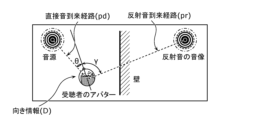
- the determination unit 1302 calculates the direct sound arrival direction ( ⁇ ) and the reflected sound arrival direction ( ⁇ ) (direction of reflected sound ( ⁇ )) determined using the avatar orientation as a reference from the direct sound arrival path (pd) and reflected sound arrival path (pr) calculated by the analysis unit 1301, and the avatar orientation information D1. That is, the determination unit 1302 detects the direct sound arrival direction ( ⁇ ) and the reflected sound arrival direction ( ⁇ ) (S231). The orientation of the avatar corresponds to the orientation of the listener.
- the avatar orientation information D1 may be included in the input signal.
- the threshold value may be determined by performing a process such as interpolation, in-placement, or extrapolation based on one or more threshold values corresponding to one or more indexes close to the calculated values of ( ⁇ ), ( ⁇ ), and (T).
- a threshold value corresponding to (20°, 265°, T) may be determined based on four threshold values corresponding to four indexes, (0°, 225°, T), (0°, 270°, T), (45°, 225°, T), and (45°, 270°, T).
- This section explains the selection process based on the difference between the angle of the direct sound arrival direction ( ⁇ ) and the angle of the reflected sound arrival direction ( ⁇ ).
- threshold data may be set that has, as an index array, a combination of the angle difference ( ⁇ ), the direction of arrival of the direct sound ( ⁇ ), and the time difference (T), or a combination of the angle difference ( ⁇ ), the direction of arrival of the reflected sound ( ⁇ ), and the time difference (T).
- threshold data may be set that has the values of ( ⁇ ), ( ⁇ ), and (T) as a three-dimensional index array, as shown in FIG. 15.
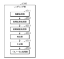
- FIG. 24 is a block diagram showing an example of the configuration for the rendering unit 1300 to perform pipeline processing.
- the rendering unit 1300 in FIG. 24 includes a reverberation processing unit 1311, an early reflection processing unit 1312, a distance attenuation processing unit 1313, a determination unit 1314, a generation unit 1315, and a binaural processing unit 1316. These multiple components may be composed of multiple components of the rendering unit 1300 shown in FIG. 7, or may be composed of at least some of the multiple components of the audio signal processing device 1001 shown in FIG. 5.
- Pipeline processing refers to dividing the process for creating sound effects into multiple processes and executing the multiple processes one by one in sequence. Each of the multiple processes performs, for example, signal processing on an audio signal, or the generation of parameters used in signal processing.
- the rendering unit 1300 may perform reverberation processing, early reflection processing, distance attenuation processing, binaural processing, and the like as pipeline processing.
- these processes are merely examples, and the pipeline processing may include other processes than these, or may not include some of the processes.
- the pipeline processing may include diffraction processing and occlusion processing.
- reverberation processing may be omitted if it is not necessary.
- Each process may be expressed as a stage.
- audio signals such as reflected sounds generated as a result of each process may be expressed as rendering items.
- the multiple stages in pipeline processing and their order are not limited to the example shown in FIG. 24.
- the reverberation processor 1311 refers to the audio signal and spatial information contained in the input signal, and calculates the reverberation using a predetermined function prepared in advance as a function for generating the reverberation.
- the early reflection processor 1312 calculates parameters for generating early reflection sounds based on spatial information.
- Early reflection sounds are reflected sounds that arrive at the listener after one or more reflections at a relatively early stage (e.g., about several tens of milliseconds after the direct sound arrives) after the direct sound from the sound source object arrives at the listener.
- the early reflection processing unit 1312 may also calculate the path of the direct sound.
- the information on the path may be used as a parameter by the early reflection processing unit 1312 to generate the early reflected sound, or may be used as a parameter by the determination unit 1314 to select the reflected sound.
- the pipeline processing may also include other processes.
- the rendering unit 1300 may also include processing units (not shown) for performing other processes included in the pipeline processing.
- the rendering unit 1300 may include a diffraction processing unit and an occlusion processing unit.
- the diffraction processing unit executes processing to generate an audio signal that indicates sound including diffracted sound caused by an obstacle object between the listener and the sound source object in a three-dimensional sound field (space).
- diffracted sound is sound that travels from the sound source object to the listener, going around the obstacle object.
- the position information given to the sound source object indicates a "point” in the virtual space as the position of the sound source object. That is, in the above, the sound source is defined as a "point sound source.”
- a sound source in a virtual space may be defined as an object having length, size, shape, etc., that is, as a spatially extended sound source that is not a point sound source.
- the distance between the listener and the sound source and the direction from which the sound is coming are not determined. Therefore, the reflected sound caused by such a sound source may be limited to being selected by the determination unit 1302 without analysis by the analysis unit 1301, or regardless of the analysis results. This makes it possible to avoid deterioration in sound quality that may occur by not selecting the reflected sound.
- a representative point such as the center of gravity of the object may be determined, and the processing of the present disclosure may be applied on the assumption that sound is generated from that representative point.
- the threshold may be adjusted according to information on the spatial extension of the sound source.
- a direct sound is a sound that is not reflected by a reflecting object
- a reflected sound is a sound that is reflected by a reflecting object
- a direct sound may be a sound that arrives at a listener from a sound source without being reflected by a reflecting object
- a reflected sound may be a sound that arrives at a listener from a sound source after being reflected by a reflecting object.
- FIG. 25 is a diagram showing sound transmission and diffraction. As shown in FIG. 25, there are cases where direct sound does not reach the listener due to the presence of an obstacle object between the sound source object and the listener. In this case, sound emitted from the sound source object, transmitted through the obstacle object, and reached the listener may be considered as direct sound. And sound emitted from the sound source object, diffracted by the obstacle object, and reached the listener may be considered as reflected sound.
- the two sounds compared in the selection process are not limited to a direct sound and a reflected sound based on a sound emitted by a single sound source.
- a sound may be selected by comparing two reflected sounds based on a sound emitted by a single sound source.
- the direct sound in this disclosure may be interpreted as the sound that reaches the listener first, and the reflected sound in this disclosure may be interpreted as the sound that reaches the listener later.
- spatial information is information about the space in which a listener who hears sound based on an audio signal is located.
- spatial information is information about a specific position (localization position) for localizing a sound image at that position in a sound space (e.g., a three-dimensional sound field), that is, for allowing the listener to perceive sound coming from a direction corresponding to the specific position.
- Spatial information includes, for example, sound source object information and position information indicating the position of the listener.
- the sound source object information may indicate the position of the sound source object placed in the sound space, the orientation of the sound source object, the directivity of the sound emitted by the sound source object, whether the sound source object belongs to a living thing, and whether the sound source object is a moving object.
- the audio signal is associated with one or more sound source objects indicated by the sound source object information.
- the bitstream has a data structure that consists of, for example, metadata (control information) and an audio signal.
- Metadata may be added to each bitstream, or may be added to multiple bitstreams collectively as information for controlling multiple bitstreams. In this case, multiple bitstreams may share metadata. Metadata may also be added for each playback time.
- one or more of the bitstreams or one or more of the files may contain information indicating the associated bitstreams or associated files.
- each of all of the bitstreams or each of all of the files may contain information indicating the associated bitstreams or associated files.
- the related bitstreams or related files are, for example, bitstreams or files that may be used simultaneously during audio processing. Also, a bitstream or file that collectively describes information indicating related bitstreams or related files may be included.
- the information indicating the related bitstream or related file may be, for example, an identifier indicating the related bitstream or related file.
- the information indicating the related bitstream or related file may be, for example, a file name indicating the related bitstream or related file, a URL (Uniform Resource Locator), or a URI (Uniform Resource Identifier), etc.
- the acquisition unit identifies and acquires the related bitstream or related file based on the information indicating the related bitstream or related file.
- a bitstream or file may contain information indicating the related bitstream or related file, and another bitstream or another file may contain information indicating the related bitstream or related file.
- the file containing information indicating the associated bitstream or associated file may be a control file such as a manifest file used for content distribution.
- Metadata may be obtained from sources other than the bitstream of the audio signal.
- the metadata for controlling the sound or the metadata for controlling the video may be obtained from sources other than the bitstream, or both may be obtained from sources other than the bitstream.
- Metadata for controlling the video may be included in the bitstream acquired by the stereophonic sound reproduction system 1000.
- the stereophonic sound reproduction system 1000 may output the metadata for controlling the video to a display device that displays the image, or a stereophonic video reproduction device that reproduces the stereophonic video.
- the metadata may include not only information for controlling audio processing, but also information for controlling video processing.
- the metadata may include only one of information for controlling audio processing and information for controlling video processing, or may include both.
- the stereophonic sound reproduction system 1000 performs acoustic processing on the audio signal using metadata included in the bitstream and interactive listener position information that is additionally acquired, thereby generating virtual acoustic effects.
- acoustic effects early reflection processing, obstacle processing, diffraction processing, blocking processing, and reverberation processing may be performed, and other acoustic processing may be performed using the metadata.
- acoustic effects such as distance attenuation effect, localization, or Doppler effect may be added.
- information for switching all or some of the sound effects on and off, or priority information for multiple sound effect processes may be added to the metadata.
- the metadata includes information about a sound space including sound source objects and obstacle objects, and information about a localization position for localizing a sound image at a specific position within the sound space (i.e., allowing a listener to perceive a sound coming from a specific direction).
- an obstacle object is an object that can affect the sound perceived by the listener, for example by blocking or reflecting the sound emitted by the sound source object before it reaches the listener.
- Obstacle objects can include stationary objects as well as moving objects such as animals or machines. Animals can also be people, etc.
- the metadata includes information that represents all or part of the shape of the sound space, the shape and position of obstacle objects in the sound space, the shape and position of sound source objects in the sound space, and the position and orientation of the listener in the sound space.
- the sound source area is determined based on the relative relationship between the listener's position and the object's position, it is possible for the listener to perceive sound E coming from the right side of the object and sound F coming from the left side of the object.
- Spatial metadata may include time to early reflections, reverberation time, and the ratio of direct sound to diffuse sound. If the ratio of direct sound to diffuse sound is zero, it is possible for the listener to perceive only direct sound.
- the determination unit 2302 may perform all or part of the processing performed by the determination unit 1302 according to the first embodiment.
- the determination unit 2302 also determines whether or not an output signal based on an audio signal created by the analysis unit 2301 (more specifically, the propagation path detection unit 2301a) is output (reproduced) by the reproduction unit 2303.
- the classification unit 2302a acquires an audio signal including attribute information that is created by the propagation path detection unit 2301a and stored in the memory 2301b.
- the classification unit 2302a outputs the audio signal to the first determination unit 2302b or the second determination unit 2302c according to the attribute specified by the attribute information included in the acquired audio signal.
- the playback unit 2303 has a first playback unit 2303a and a second playback unit 2303b.
- the first playback unit 2303a outputs an output signal (first output signal) based on a sound signal whose attribute is a predetermined sound different from indirect sound.
- the second playback unit 2303b outputs an output signal (second output signal) based on a sound signal whose attribute is indirect sound.
- the first reproduction unit 2303a performs binaural filtering on the acquired audio signal to generate and output a first output signal.
- the binaural filtering is achieved, for example, by processing the acquired audio signal using a head-related transfer function.
- the second reproduction unit 2303b performs binaural filtering and diffusion filtering on the acquired audio signal to generate and output a second output signal.
- Diffusion filtering is, for example, a process for improving the reality of indirect sound by diffusing the indirect sound represented by the acquired audio signal.
- Diffusion filtering is a process using a filter that realistically simulates the auditory strength of the sound diffusion represented by the acquired audio signal (i.e., simulates the auditory strength of the sound diffusion felt by the listener). In diffusion filtering, a finite impulse filter and/or an infinite impulse filter is used.
- the analysis unit 2301 analyzes the input signal and calculates values related to the path taken by each of the direct sound and reflected sound to reach the listening position, the time it takes for each sound to arrive, and the volume at the time of arrival, as well as a value related to the time difference between the direct sound and the reflected sound, and a value related to the volume ratio between the direct sound and the reflected sound at the listening position.
- the propagation path detection unit 2301a calculates the characteristics of the direct sound represented by the created audio signal and the reflected sound represented by the created audio signal. Specifically, the arrival time and volume of the direct sound and reflected sound at the time of arrival at the listener (listening position) are calculated. The method of calculating the arrival time and volume of the direct sound and reflected sound can be the same as that shown in embodiment 1.
- the volume when the reflected sound arrives means the volume when the reflected sound, which is an example of an indirect sound, arrives at the listening position, or in other words, the volume of the indirect sound (reflected sound) at the listening position.
- the volume ratio (L) is the volume ratio between the direct sound and the reflected sound (indirect sound) at the listening position.
- the volume ratio (L) and the time difference (T) can be calculated using the method shown in the first embodiment.
- the classification unit 2302a also acquires the volume (ld) at the time of direct sound arrival, the volume (lr) at the time of reflected sound arrival, the volume ratio (L), and the time difference (T) calculated by the propagation path detection unit 2301a.
- the second determination process is a process for determining whether or not the acquired audio signal satisfies the second condition.
- the second determination process if the volume ratio between the direct sound (predetermined sound) and the reflected sound (indirect sound) when they arrive at the listening position is equal to or greater than a second threshold determined according to the time difference between the direct sound and the reflected sound, the acquired audio signal is determined to satisfy the second condition.
- the second determination process corresponds to the process performed by the determination unit 1302 in the first embodiment.
- the time difference is calculated by the propagation path detection unit 2301a, and the second determination unit 2302c obtains the calculated time difference and performs the second determination process.
- the reflected sound and the direct sound related to the reflected sound come from the same sound source.
- the time difference between the direct sound and the reflected sound is, for example, but not limited to, the time difference between the direct sound arrival time (arrival time) and the reflected sound arrival time (arrival time).
- the volume ratio between the direct sound and the reflected sound when the reflected sound and the direct sound arrive at the listening position corresponds to the volume ratio (L) in the first embodiment, which is the ratio between the volume when the direct sound arrives (ld) and the volume when the reflected sound arrives (lr).
- the first determination process is a process performed on an audio signal whose attribute is indirect sound (reflected sound) and an audio signal whose attribute is information indicating a predetermined sound (direct sound).
- the first judgment process is a process for judging whether or not the acquired audio signal satisfies a first condition.
- the first judgment process if the amplitude value of the acquired audio signal is equal to or greater than a first threshold, the acquired audio signal is judged to satisfy the first condition.
- the amplitude value of an audio signal corresponds to the volume of the sound (reflected sound (indirect sound) or direct sound (predetermined sound)) represented by the audio signal, in the first judgment process, if the volume of the sound represented by the acquired audio signal is equal to or greater than a certain level, the acquired audio signal is judged to satisfy the first condition.
- the first threshold is a constant value that does not depend on the time difference between the direct sound and the reflected sound (indirect sound).
- the first threshold is a value related to the volume of the acquired audio signal, in other words, a value related to the amplitude value. More specifically, the first threshold indicates the volume at the boundary between whether or not a sound can be perceived by a listener, and is a threshold for determining that a sound with a volume lower than the threshold is not to be reproduced.
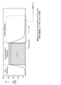
- FIG. 28 is a graph showing threshold data indicating the first threshold according to this embodiment.
- the first threshold is -70 dB, and since the amplitude value of audio signal B shown in FIG. 28 is equal to or greater than the first threshold, audio signal B is determined to satisfy the first condition. Also, since the amplitude value of audio signal A shown in FIG. 28 is less than the first threshold, audio signal A is determined to not satisfy the first condition.
- the playback unit 2303 acquires the audio signal output from the determination unit 2302 and outputs an output signal based on the audio signal (S503).
- the first determination unit 2302b does not output the audio signal to the reproduction unit 2303 (first reproduction unit 2303a). In such a case, the first reproduction unit 2303a does not output an output signal based on the audio signal, thereby reducing the amount of calculation and the calculation load.
- the second determination unit 2302c does not output the audio signal to the reproduction unit 2303 (second reproduction unit 2303b) if the audio signal does not satisfy the first condition, and does not output the audio signal to the reproduction unit 2303 (second reproduction unit 2303b) if the audio signal does not satisfy the second condition.
- the second reproduction unit 2303b does not output an output signal based on the audio signal, thereby reducing the amount of calculation and the calculation load.
- the acquisition step acquires an audio signal that includes attribute information that identifies an attribute of the audio signal.
- the determination step performs a first determination process to determine whether the acquired audio signal satisfies a first condition when the attribute identified by the attribute information included in the acquired audio signal is information indicating indirect sound, and a second determination process to determine whether the acquired audio signal satisfies a second condition different from the first condition.
- the reproduction step outputs an output signal based on the acquired audio signal when the acquired audio signal satisfies the first condition and the second condition.
- a first judgment process and a second judgment process are performed on an audio signal whose attribute is indirect sound (reflected sound), and an output signal based on the acquired audio signal is output if the audio signal satisfies the first condition and the second condition. That is, it is appropriately determined whether or not an output signal based on an audio signal whose attribute is indirect sound (reflected sound) is to be output. If an output signal is not output, the amount of calculation and the calculation load are reduced. In other words, it is possible to realize an audio signal processing method that can appropriately reduce the amount of calculation and the calculation load.
- the acquired audio signal in the first determination process, if the amplitude value of the acquired audio signal is equal to or greater than a first threshold, the acquired audio signal is determined to satisfy the first condition.
- the second determination process if the volume ratio between the direct sound and the indirect sound related to the indirect sound when they arrive at the listening position where the listener is located is equal to or greater than a second threshold determined according to the time difference between the arrival of the direct sound and the indirect sound, the acquired audio signal is determined to satisfy the second condition.
- the audio signal is determined to satisfy the first condition if the amplitude value is equal to or greater than the first threshold, and in the second determination process, the audio signal is determined to satisfy the second condition if the volume ratio is equal to or greater than the second threshold.
- an output signal based on the acquired audio signal is output. In other words, it is more appropriately determined whether or not an output signal based on the audio signal is output. In other words, it is possible to realize an audio signal processing method that can more appropriately reduce the amount of calculation and the calculation load.
- the first judgment unit 2302b and the second judgment unit 2302c are provided, but this is not limited thereto.
- the first judgment unit 2302b may not be provided, and the second judgment unit 2302c may be provided.
- the second judgment unit 2302c acquires both an audio signal whose attribute is a predetermined sound (direct sound) and an audio signal whose attribute is an indirect sound (reflected sound), and performs a first judgment process on both of them. If the first judgment process determines that the audio signal whose attribute is a predetermined sound (direct sound) satisfies the first condition, the audio signal is output to the first reproduction unit 2303a, and the first reproduction unit 2303a outputs a first output signal based on the output audio signal.
- Fig. 29 is a block diagram showing an example of the configuration of the rendering unit 3300 according to the present embodiment.
- the rendering unit 3300 includes an analysis unit 2301, a determination unit 3302, and a playback unit 3303.
- the determination unit 3302 has the same configuration as the determination unit 2302 according to the second embodiment, except that it has a second determination unit 3302c instead of the first determination unit 2302c.
- the playback unit 3303 has the same configuration as the playback unit 2303 in embodiment 2, except that it further includes a gain setting unit 3303c.
- the gain setting unit 3303c outputs the determined gain to the judgment unit 3302 (more specifically, the second judgment unit 3302c).
- the second determination unit 3302c performs a first determination process to determine whether the audio signal output from the classification unit 2302a satisfies a first condition. In this embodiment, the second determination unit 3302c does not perform the second determination process.
- the analysis unit 2301 outputs the audio signal stored in the memory 2301b to the renderer pipeline unit 4304.
- the first processing unit 4304a1 When the acquired audio signal has been processed by the initial reflection processing unit 1312, the first processing unit 4304a1 performs a first process of determining the amount by which to increase or decrease the amplitude of the audio signal.
- the first processing unit 4304a may perform a process of determining the amount by which to increase or decrease the amplitude of the audio signal as the first process.
- the acquired audio signal is output to the determination unit 4302, where it is processed.
- the second processing unit 4304b2 When the binaural filter processing described above is performed on the acquired audio signal, the second processing unit 4304b2 performs a process of determining the amount by which to increase or decrease the amplitude of the audio signal as the second process.
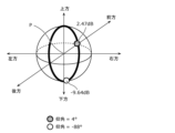
- a sphere centered at listening position P is shown, and on the sphere, circles are shown along the listener's horizontal plane, median plane, and frontal plane.
- the circle along the listener's horizontal plane is shown in bold
- Figure 33 the circle along the listener's median plane is shown in bold
- Figure 34 the circle along the listener's frontal plane is shown in bold.
- the energy of the head-related transfer function differs for each localization direction.
- the energy of the head-related transfer function is shown converted to dB when the energy of a transfer function with a transfer characteristic of 1 is set to 0 dB.
- FIGS. 31 to 34 show the energy of an example head-related transfer function, but the energy varies greatly depending on the head-related transfer function used.
- a process is performed to determine the amount of increase or decrease depending on the head-related transfer function used.
- the second processing units 4304b1 and 4304b2 each perform the second processing described above and output the determined increase or decrease amount to the second gain accumulation unit 4306.
- the first gain accumulation unit 4305 calculates the first amount of increase or decrease.
- the first amount of increase or decrease is an amount of increase or decrease determined by each of the multiple first processes (more specifically, each of the multiple first processing units 4304a), and is a value obtained by accumulating the amount of increase or decrease that amplifies the amplitude of the acquired audio signal. More specifically, the first gain accumulation unit 4305 calculates the first amount of increase or decrease by accumulating the amount of increase or decrease to the reference volume. In other words, the first amount of increase or decrease is a value obtained by accumulating the amount of increase or decrease determined by each of the multiple first processing units 4304a and the reference volume.
- the multiple first processing units 4304a determine multiple (here, four) amounts of gain or loss for the acquired audio signal. Each of the multiple first processing units 4304a outputs the determined amount of gain or loss to the first gain accumulation unit 4305.
- the first gain accumulation unit 4305 acquires the multiple output amounts of gain or loss and calculates a first amount of gain or loss by accumulating the multiple (four) amounts of gain or loss and a reference volume.
- the first gain accumulation unit 4305 outputs the calculated first amount of gain or loss to the second gain accumulation unit 4306, and the second gain accumulation unit 4306 acquires the output first amount of gain or loss.
- the second gain accumulation unit 4306 calculates a second amount of increase or decrease.
- the second amount of increase or decrease is an amount of increase or decrease determined by each of the multiple second processes (more specifically, each of the multiple second processing units 4304b), and is a value obtained by accumulating the amounts of increase or decrease that amplify the amplitude of the acquired audio signal. More specifically, the second gain accumulation unit 4306 accumulates the amounts of increase or decrease, and further accumulates the first amount of increase or decrease output from the first gain accumulation unit 4305 to the accumulated amount of increase or decrease, thereby calculating the second amount of increase or decrease.
- the second amount of increase or decrease is a value obtained by accumulating the amounts of increase or decrease determined by each of the multiple second processing units 4304b and the first amount of increase or decrease.
- the second processing units 4304b determine multiple (here, two) amounts of increase or decrease for the acquired audio signal. Each of the second processing units 4304b outputs a parameter indicating the determined amount of increase or decrease to the second gain accumulation unit 4306.
- the second gain accumulation unit 4306 acquires the multiple output parameters and calculates the second amount of increase or decrease by accumulating the amount of increase or decrease indicated by each of the multiple parameters and the first amount of increase or decrease.
- the second process may be a sound quality adjustment function performed by the listener's selection, and may involve increasing or decreasing the amplitude of the signal.
- the second amount of increase or decrease may include the amount of increase or decrease in amplitude due to the sound quality adjustment function set by the listener of the virtual space.
- the listener may make a selection by, for example, operating the operation reception unit, the operation reception unit may accept the selection, and the second gain accumulation unit 4306 may calculate the second amount of increase or decrease based on the selection accepted by the operation reception unit.
- the listener may make a selection that results in the sound quality of his or her preference, and thereby be able to listen to sound with the sound quality of his or her preference.
- the second amount of increase or decrease may further include the amount of increase or decrease in amplitude due to the sound quality adjustment function that is set by the selection of the administrator of the virtual space instead of the listener of the virtual space.
- the determination unit 4302 performs a first determination process on the audio signal acquired by the renderer pipeline unit 4304. In the first determination process, if the first increase/decrease amount (G1) calculated by the first gain accumulation unit 4305 is equal to or greater than the first threshold value (T1), it is determined that the acquired audio signal satisfies the first condition.
- the first threshold value in this embodiment is a fixed value and is a value related to the volume of the audio signal, in other words, a value related to the amplitude value. In other words, the first threshold value in this embodiment is the same as the first threshold value described in embodiment 2.
- the determination unit 4302 performs a second determination process on the audio signal acquired by the renderer pipeline unit 4304. In the second determination process, if the value corresponding to the second increase or decrease calculated by the second gain accumulation unit 4306 is equal to or greater than the second threshold, it is determined that the acquired audio signal satisfies the second condition.
- the second increase or decrease calculated by the second gain accumulation unit 4306 corresponds to the volume (Ir) at the time of arrival of the reflected sound shown in the first and second embodiments, that is, it indicates the volume when the reflected sound indicated by the acquired audio signal arrives at the listening position.
- the value corresponding to the second amount of increase or decrease is the ratio (volume ratio) between the volume of the direct sound related to the indirect sound (reflected sound) indicated by the acquired audio signal and the second amount of increase or decrease calculated by the second gain accumulation unit 4306.
- the value corresponding to the second amount of increase or decrease corresponds to the volume ratio (L) shown in the second embodiment, which is the ratio between the volume when the direct sound arrives (ld) and the volume when the reflected sound arrives (lr).
- the second determination process according to the second embodiment if the volume ratio (L) between the direct sound and the indirect sound when the indirect sound and the direct sound arrive at the listening position is equal to or greater than a second threshold, the acquired audio signal is determined to satisfy the second condition.
- the second determination process according to the present embodiment is the same as the second determination process according to the second embodiment, except that the volume ratio between the direct sound and the indirect sound is changed to a value according to the second increase or decrease amount.
- the second determination process if the first determination process determines that the acquired audio signal does not satisfy the first condition, the second determination process is not performed. Also, if the first determination process determines that the acquired audio signal does satisfy the first condition, the second determination process is performed.
- the second amount of increase or decrease is calculated before the second determination process is performed.
- the second process performed by the second processing unit 4304b uses processing based on the auditory perceptual characteristics of the listener, and is therefore a process that determines the amount of increase or decrease without relying on the audio signal (i.e., statically). For this reason, the second amount of increase or decrease can be calculated before the second determination process is performed.
- the determination unit 4302 outputs the acquired audio signal to a plurality of second processing units 4304b, and further, the renderer pipeline unit 4304 outputs the acquired audio signal to the playback unit 4303.
- the renderer pipeline unit 4304 may also output the second increase/decrease amount calculated by the second gain accumulation unit 4306 to the playback unit 4303. Then, processing is performed in the playback unit 4303.
- the analysis unit 2301 performs an analysis process to analyze the input signal (S601).
- each of the multiple first processing units 4304a determines the amount of increase or decrease by which to amplify the amplitude of the acquired audio signal (S603).
- Each of the multiple first processing units 4304a outputs the determined amount of increase or decrease to the first gain accumulation unit 4305.
- the analysis unit 2301 outputs the reference volume of the indirect sound (reflected sound) to the first gain accumulation unit 4305.
- the second gain accumulation unit 4306 acquires the output multiple (two) amounts of increase/decrease and the calculated first amount of increase/decrease, and accumulates the acquired multiple amounts of increase/decrease and the acquired first amount of increase/decrease to calculate a second amount of increase/decrease (S606). Then, the second gain accumulation unit 4306 outputs the calculated second amount of increase/decrease to the determination unit 4302.
- the second determination process is performed.
- the audio signal processing method is an audio signal processing method executed by an audio signal processing device, and includes an acquisition step, a renderer pipeline step, a playback step, a first gain accumulation step, and a second gain accumulation step.
- the acquisition step acquires an audio signal indicative of indirect sound.
- the renderer pipeline step performs one or more first processes, a first determination process, a second determination process, and one or more second processes different from the one or more first processes on the acquired audio signal.
- the first gain accumulation step includes a reproducing step of outputting an output signal based on the acquired audio signal, and accumulating the amount of increase or decrease determined by each of one or more first processes, which amplifies the amplitude of the acquired audio signal, to calculate a first amount of increase or decrease.
- the second gain accumulation step includes accumulating the amount of increase or decrease determined by each of one or more second processes, which amplifies the amplitude of the acquired audio signal, to calculate a second amount of increase or decrease.
- the first determination process if the calculated first amount of increase or decrease is equal to or greater than a first threshold, it is determined that the acquired audio signal satisfies the first condition. If it is determined that the acquired audio signal does not satisfy the first condition, the second determination process is not performed.
- the second determination process is performed. In the second determination process, if a value corresponding to the calculated second amount of increase or decrease is equal to or greater than a second threshold different from the first threshold, it is determined that the acquired audio signal satisfies the second condition, and a reproducing step is performed if it is determined that the acquired audio signal satisfies the second condition.
- the second amount of increase or decrease calculated in the second gain accumulation step is an amount of increase or decrease when a diffusion filter process is performed to improve the reality of the indirect sound by diffusing the indirect sound, and includes an amount of increase or decrease that amplifies the amplitude of the acquired audio signal.
- the above value is the ratio between the volume of the direct sound related to the indirect sound and the second amount of increase or decrease calculated in the second gain accumulation step, and the second threshold is determined according to the time difference between the arrival of the direct sound and the indirect sound.
- the second determination process if the ratio is equal to or greater than the second threshold, it is determined that the audio signal indicating indirect sound satisfies the second condition, and an output signal based on the acquired audio signal is output when such second condition is satisfied. In other words, it is more appropriately determined whether or not an output signal based on an audio signal indicating indirect sound is output. In other words, it is possible to realize an audio signal processing method that can more appropriately reduce the amount of calculation and the calculation load.
- the second amount of increase or decrease calculated in the second gain accumulation step includes the amount of increase or decrease in amplitude due to the sound quality adjustment function set by the listener's selection.
- the above value is the ratio between the volume of the direct sound related to the indirect sound and the second amount of increase or decrease calculated in the second gain accumulation step, and the second threshold is determined according to the time difference between the arrival of the direct sound and the indirect sound.
- the first threshold value is a value related to the volume.
- parameters are acquired that indicate the amount of increase or decrease determined by each of one or more second processes and that amplify the amplitude of the acquired audio signal, and the second amount of increase or decrease is calculated according to the acquired multiple parameters.
- the second increase or decrease amount according to the above parameters is calculated, so that it is possible to more appropriately determine whether or not an output signal based on a sound signal whose attribute is indirect sound is to be output. In other words, it is possible to realize a sound signal processing method that can more appropriately reduce the amount of calculation and the calculation load.
- the rendering unit 5300 has the same configuration as the rendering unit 4300 according to the fourth embodiment, except that it further includes a modification unit 5307 and an invalidation unit 5308.
- the first threshold value set by the change unit 5307 may have a different value when the invalidation process is performed and when the invalidation process is not performed. More specifically, the first threshold value set when the invalidation process is performed may be greater than the first threshold value set when the invalidation process is not performed. The setting of the first threshold value and the effect of the invalidation process are described below with reference to FIG. 37.
- FIG. 37 shows a table illustrating the setting of the first threshold and the effect of the invalidation process in this embodiment.
- the “thinning number” indicates the number of audio signals (more specifically, multiple audio signals) acquired by the renderer pipeline unit 4304 that are not output as output signals from the playback unit 4303.
- “O” is shown
- “X” is shown.
- the storage area that stores the value indicating the first threshold set by the change unit 5307 and the storage area that stores the signal instructing the execution of the invalidation process are adjacent areas. This is because not only is it easy to visually grasp the setting value by being adjacent to each other, but also because they are adjacent in terms of memory area, a special effect is obtained in that both values can be set simultaneously (with one memory access process).
- the value indicating the first threshold and the signal instructing to perform the invalidation process are linked and arranged in the upper and lower bit fields of an area accessible by a single address, and the series of data arranged in this manner is written in a single memory access, allowing the two pieces of data to be set simultaneously.
- the second determination process is no longer performed due to the invalidation process, and the amount of calculation and calculation load required to perform the second determination process can be reduced.
- the first threshold value set when the invalidation process is performed is greater than the first threshold value set when the invalidation process is not performed.
- being equal to or greater than the threshold value and being greater than the threshold value may be interpreted as interchangeable.
- being equal to or less than the threshold value and being smaller than the threshold value may be interpreted as interchangeable.
- time and hour may be interpreted as interchangeable.
- the process of selecting one or more processing target sounds from a plurality of sounds if there is no sound that satisfies the conditions, then none of the sounds may be selected as processing target sounds.
- the process of selecting one or more processing target sounds from a plurality of sounds may include cases in which no processing target sound is selected.
- an expression "at least one of a first element, a second element, and a third element” may correspond to a first element, a second element, a third element, or any combination thereof.
- the aspects understood based on this disclosure are described as being implemented as an audio signal processing device, an encoding device, or a decoding device.
- the aspects understood based on this disclosure are not limited to these, and may be implemented as software for executing an audio signal processing method, an encoding method, or a decoding method.
- a program for executing the above-mentioned audio signal processing method, encoding method, or decoding method may be stored in a computer-readable recording medium.
- the computer may then record the program stored in the recording medium in the computer's RAM and operate according to the program.
- the above components may be realized as an LSI, which is an integrated circuit typically having input and output terminals. These may be individually formed into single chips, or may be formed into a single chip that includes all or some of the components of the embodiments. Depending on the degree of integration, the LSI may be expressed as an IC, a system LSI, a super LSI, or an ultra LSI.
- the FPGA or CPU, etc. may download all or part of the software for realizing the audio signal processing method, encoding method, or decoding method described in this disclosure via wireless or wired communication. Furthermore, all or part of the software for updates may be downloaded via wireless or wired communication. Then, the FPGA or CPU, etc. may store the downloaded software in memory and operate based on the stored software to execute the digital signal processing described in this disclosure.
- the device equipped with an FPGA or a CPU, etc. may be connected to the signal processing device wirelessly or via a wire, or may be connected to the signal processing server via a network.
- This device and the signal processing device or the signal processing server may then perform the audio signal processing method, encoding method, or decoding method described in this disclosure.
- a server may provide software related to the acoustic processing, encoding processing, or decoding processing of the present disclosure. Then, a terminal or device may operate as an audio signal processing device, encoding device, or decoding device described in the present disclosure by installing the software. Note that the terminal or device may be connected to a server via a network and the software may be installed.
- a device other than the terminal or device may connect to a server via a network to obtain data for installing the software, and the other device may provide the data for installing the software to the terminal or device, thereby installing the software in the terminal or device.
- An example of the software may be VR software or AR software for causing a terminal or device to execute the audio signal processing method described in the embodiment.
- each component may be configured with dedicated hardware, or may be realized by executing a software program suitable for each component.
- Each component may be realized by a program execution unit such as a CPU or processor reading and executing a software program recorded on a recording medium such as a hard disk or semiconductor memory.
- Audio signal processing device 1002 Audio presentation device 1100, 1120, 1500 Encoding device 1101, 1113 Input data 1102 Encoder 1103 Encoded data 1104, 1114, 1404, 1503, 2301b Memory 1110, 1130 Decoding device 1111 Audio signal 1112, 1200, 1210 Decoder 1121 Transmitting unit 1122 Transmitted signal 1131 Receiving unit 1132 Received signal 1201, 1211 Spatial information management unit 1202 Audio data decoder 1203, 1213, 1300, 2300, 3300, 4300, 5300 Rendering unit 1301, 2301 Analysis unit 1302, 1314, 2302, 3302, 4302 Determination unit 1303, 2303, 3303, 4303 Reproduction unit 1304 Threshold adjustment unit 1311 Reverberation processing unit 1312 Early reflection processing unit 1313 Distance attenuation processing unit 1315 Generation unit 1316 Binaural processing unit 1401 Speaker 1402, 1501 Processor 1403, 1502 Communication IF 1405 Sensor 2301a Propagation path detection unit 2302a
Landscapes
- Physics & Mathematics (AREA)
- Engineering & Computer Science (AREA)
- Acoustics & Sound (AREA)
- Signal Processing (AREA)
- Stereophonic System (AREA)
Abstract
Description
従来、仮想空間又は実空間において、仮想的な音源が発した音に対して当該空間の環境に応じて生じる音響効果を付与してイマーシブオーディオを受聴者に提供する音声信号処理技術が検討されてきた。
(立体音響再生システムの例)
図2は、立体音響再生システム1000の一例を示す図である。具体的には、図2は、本開示の音響処理又は復号処理が適用可能なシステムの一例である立体音響再生システム1000を示す。立体音響は、イマーシブオーディオ(Immersive Audio)とも表現される。立体音響再生システム1000は、音声信号処理装置1001と音声提示装置1002を含む。
図3Aは、符号化装置1100の構成例を示すブロック図である。具体的には、図3Aは、本開示の符号化装置の一例である符号化装置1100の構成を示す。
図3Bは、復号装置1110の構成例を示すブロック図である。具体的には、図3Bは、本開示の復号装置の一例である復号装置1110の構成を示す。
図3Cは、符号化装置の別の構成例を示すブロック図である。具体的には、図3Cは、本開示の符号化装置の別の一例である符号化装置1120の構成を示す。図3Cでは、図3Aの構成要素と同じ構成要素に図3Aの符号と同じ符号を付しており、これらの構成要素については説明を省略する。
図3Dは、復号装置の別の構成例を示すブロック図である。具体的には、図3Dは、本開示の復号装置の別の一例である復号装置1130の構成を示す。図3Dでは、図3Bの構成要素と同じ構成要素に図3Bの符号と同じ符号を付しており、これらの構成要素については説明を省略する。
図4Aは、デコーダ1200の構成例を示すブロック図である。具体的には、図4Aは、図3B又は図3Dにおけるデコーダ1112の一例であるデコーダ1200の構成を示す。
図5は、音声信号処理装置1001の物理的構成の一例を示す図である。なお、図5の音声信号処理装置1001は、図3Bの復号装置1110又は図3Dの復号装置1130であってもよい。図3B又は図3Dに示された複数の構成要素は、図5に示された複数の構成要素によって実装されてもよい。また、ここで説明する構成の一部は音声提示装置1002に備えられていてもよい。
図6は、符号化装置1500の物理的構成の一例を示す図である。図6の符号化装置1500は、図3Aの符号化装置1100又は図3Cの符号化装置1120であってもよく、図3A又は図3Cに示された複数の構成要素が、図6に示された複数の構成要素によって実装されてもよい。
図7は、レンダリング部1300の構成例を示すブロック図である。具体的には、図7は、図4A及び図4Bのレンダリング部1203及び1213に対応するレンダリング部1300の詳細な構成の一例を示す。
図8は、音声信号処理装置1001の動作例を示すフローチャートである。図8には、主に音声信号処理装置1001のレンダリング部1300で実行される処理が示されている。
反射音を生成するか否かの選択処理の詳細について説明する。
選択処理に用いられる閾値データは、例えば既に知られている先行音効果に基づくエコー検知限の値、又は、ポストマスキング効果に基づくマスキング閾値を参考に設定されてもよい。
本実施の形態に係る閾値データは、音声信号処理装置1001のメモリ1404に記憶される。記憶しておく閾値データの形式及び種類は、任意の形式及び任意の種類であってよい。複数の形式及び複数の種類の閾値が記憶される場合、選択処理において、いずれの形式及びいずれの種類の閾値を反射音の選択処理に用いるかが決定されてもよい。いずれの閾値データを選択処理に用いるかを決定する方法については、後述する。

図12A、図12B及び図12Cの例において、複数の形式及び複数の種類の閾値が空間情報管理部1201及び1211に記憶されてもよい。そして、複数の形式及び複数の種類の閾値のうち、いずれの形式及びいずれの種類の閾値を反射音の選択処理に用いるかが決定されてもよい。具体的には、図12Cの例示3に示すように、反射音到来時刻に対応する時間差(T)において、最も高い閾値が採用されてもよい。
閾値の設定方法の別の例として、直接音の性質に応じて閾値を設定する方法について説明する。
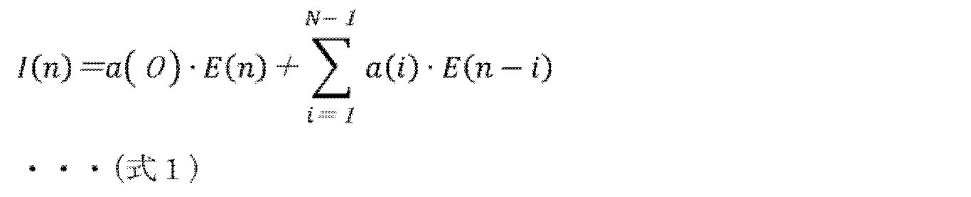

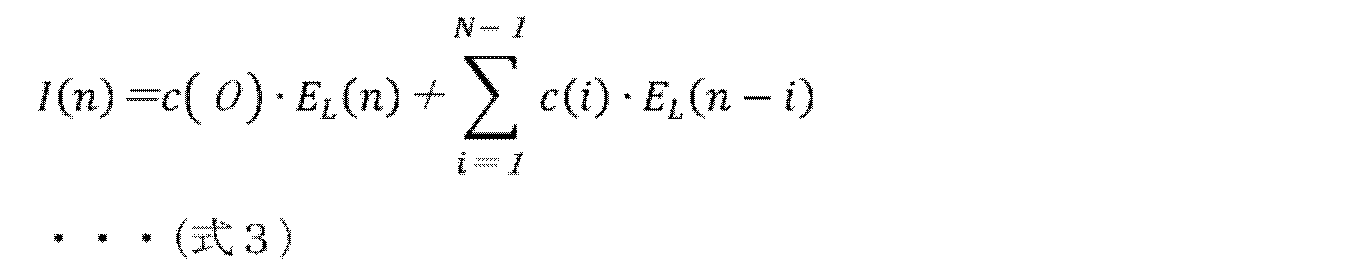

閾値の設定方法の別の例として、当該仮想空間の再現を処理する演算資源(CPU能力、メモリ資源、PC性能又はバッテリ残量等)に応じて、閾値が設定されてもよい。より具体的には、音声信号処理装置1001のセンサ1405が演算資源の量を検知し、演算資源量が少ない場合、閾値が高く設定される。これにより、より多くの反射音の音量が閾値よりも小さくなるため、バイノーラル処理が行われる反射音を減らすことが可能になり、演算量を減らすことが可能になる。
閾値の設定方法の別の例として、図示しない閾値設定部を音声信号処理装置1001又は音声提示装置1002が備えることで、当該仮想空間の管理者又は受聴者によって閾値が設定されてもよい。
図20は、音声信号処理装置1001の動作の第1変形例を示すフローチャートである。図20には、主に音声信号処理装置1001のレンダリング部1300で実行される処理が示されている。本変形例では、レンダリング部1300の動作に音量補償処理が追加される。
図21は、音声信号処理装置1001の動作の第2変形例を示すフローチャートである。図21には、主に音声信号処理装置1001のレンダリング部1300で実行される処理が示されている。本変形例では、レンダリング部1300の動作に左右音量差調整処理が追加される。
到来方向に応じた閾値を設定する方法について説明する。
上述の解析部1301、判定部1302及び再生部1303で行われる処理は、例えば特許文献3で説明されているようなパイプライン処理として行われてもよい。
上記では、音源オブジェクトに付与される位置情報は、仮想空間内における「点」を音源オブジェクトの位置として示す。すなわち、上記では、音源は、「点音源」として定義されている。
例えば、直接音は、反射オブジェクトによって反射されていない音であり、反射音は、反射オブジェクトによって反射された音である。直接音は、音源から反射オブジェクトによって反射することなく受聴者に到来した音であってもよいし、反射音は、音源から反射オブジェクトによって反射して受聴者に到来した音であってもよい。
ビットストリームには、例えば、音声信号とメタデータとが含まれる。音声信号は、音が表現された音データであって、音の周波数及び強弱に関する情報等を示す。また、メタデータは、音場の空間である音空間に関する空間情報を含む。
メタデータは、音空間で表現されるシーンの記述に用いられる情報であってもよい。ここで、シーンとは、メタデータを用いて立体音響再生システム1000でモデリングされる音空間における三次元映像及び音響イベントを表す全ての要素の集合体を指す用語である。
以下、実施の形態2について説明する。以下では、実施の形態1との相違点を中心に説明し、共通点の説明を省略又は簡略化する。
まず、本実施の形態に係るレンダリング部2300の構成について説明する。図26は、本実施の形態に係るレンダリング部2300の構成例を示すブロック図である。
図27は、本実施の形態に係る音声信号処理装置の動作例を示すフローチャートである。図27には、主に本実施の形態に係る音声信号処理装置が備えるレンダリング部2300で実行される処理が示されている。
以下、実施の形態3について説明する。以下では、実施の形態2との相違点を中心に説明し、共通点の説明を省略又は簡略化する。
まず、本実施の形態に係るレンダリング部3300の構成について説明する。図29は、本実施の形態に係るレンダリング部3300の構成例を示すブロック図である。
以下、実施の形態4について説明する。以下では、実施の形態2との相違点を中心に説明し、共通点の説明を省略又は簡略化する。
まず、本実施の形態に係るレンダリング部4300の構成について説明する。図30は、本実施の形態に係るレンダリング部4300の構成例を示すブロック図である。
図35は、本実施の形態に係る音声信号処理装置の動作例を示すフローチャートである。図35には、主に本実施の形態に係る音声信号処理装置が備えるレンダリング部4300で実行される処理が示されている。
以下、実施の形態5について説明する。以下では、実施の形態4との相違点を中心に説明し、共通点の説明を省略又は簡略化する。
まず、本実施の形態に係るレンダリング部5300の構成について説明する。図36は、本実施の形態に係るレンダリング部5300の構成例を示すブロック図である。
なお、本開示に基づいて把握される態様は、実施の形態に限定されず、種々変更して実施されてもよい。
1001 音声信号処理装置(音響処理装置)
1002 音声提示装置
1100、1120、1500 符号化装置
1101、1113 入力データ
1102 エンコーダ
1103 符号化データ
1104、1114、1404、1503、2301b メモリ
1110、1130 復号装置
1111 音声信号
1112、1200、1210 デコーダ
1121 送信部
1122 送信信号
1131 受信部
1132 受信信号
1201、1211 空間情報管理部
1202 音声データデコーダ
1203、1213、1300、2300、3300、4300、5300 レンダリング部
1301、2301 解析部
1302、1314、2302、3302、4302 判定部
1303、2303、3303、4303 再生部
1304 閾値調整部
1311 残響処理部
1312 初期反射処理部
1313 距離減衰処理部
1315 生成部
1316 バイノーラル処理部
1401 スピーカ
1402、1501 プロセッサ
1403、1502 通信IF
1405 センサ
2301a 伝播経路検出部
2302a 分類部
2302b 第1判定部
2302c、3302c 第2判定部
2303a 第1再生部
2303b 第2再生部
3303c ゲイン設定部
4304 レンダラーパイプライン部
4304a、4304a1、4304a2、4304a3、4304a4 第1処理部
4304b、4304b1、4304b2 第2処理部
4305 第1ゲイン累積部
4306 第2ゲイン累積部
5307 変更部
5308 無効化部
Claims (17)
- 音声信号処理装置が実行する音声信号処理方法であって、
音声信号であって、前記音声信号の属性を特定する属性情報を含む音声信号を取得する取得ステップと、
取得された前記音声信号が含む前記属性情報によって特定される前記属性が間接音を示す情報である場合に、取得された前記音声信号が、第1条件を満たすか否かを判定する第1判定処理及び前記第1条件とは異なる第2条件を満たすか否かを判定する第2判定処理を行う判定ステップと、
取得された前記音声信号が前記第1条件及び前記第2条件を満たす場合に、取得された前記音声信号に基づく出力信号を出力する再生ステップと、を含む、
音声信号処理方法。 - 前記間接音は、反射音である、
請求項1に記載の音声信号処理方法。 - 取得された前記音声信号が含む前記属性情報によって特定される前記属性が前記間接音とは異なる所定音を示す情報である場合に、
前記判定ステップでは、前記第2判定処理が行われない、
請求項1又は2に記載の音声信号処理方法。 - 前記所定音は、直接音である、
請求項3に記載の音声信号処理方法。 - 前記第1判定処理では、取得された前記音声信号の振幅値が第1閾値以上である場合に、取得された前記音声信号が前記第1条件を満たすと判定され、
前記第2判定処理では、前記間接音に係る直接音及び前記間接音が受聴者が居る位置である受聴位置に到来するときの前記直接音と前記間接音との音量比が、前記直接音と前記間接音との到来する時間差に応じて決定される第2閾値以上である場合に、取得された前記音声信号が前記第2条件を満たすと判定される、
請求項1~4のいずれか1項に記載の音声信号処理方法。 - 前記再生ステップは、
前記属性が前記間接音とは異なる所定音である前記音声信号に基づく第1出力信号を出力する第1再生ステップと、
前記属性が前記間接音である前記音声信号に基づく第2出力信号を出力する第2再生ステップと、
を含み、
前記第2再生ステップでは、取得された前記音声信号に、前記間接音を拡散することで前記間接音のリアリティを向上させる拡散フィルタ処理を行うことで、前記第2出力信号を出力し、
前記第1再生ステップでは、取得された前記音声信号に、前記拡散フィルタ処理を施さずに、前記第1出力信号を出力する、
請求項1~5のいずれか1項に記載の音声信号処理方法。 - 前記第1判定処理が行われた後に、前記第2判定処理が行われる、
請求項1~6のいずれか1項に記載の音声信号処理方法。 - 音声信号処理装置が実行する音声信号処理方法であって、
間接音を示す音声信号を取得する取得ステップと、
取得された前記音声信号について、1以上の第1処理、第1判定処理、第2判定処理、及び、前記1以上の第1処理とは異なる1以上の第2処理を行うレンダラーパイプラインステップと、
取得された前記音声信号に基づく出力信号を出力する再生ステップと、
前記1以上の第1処理のそれぞれによって決定された増減量であって、取得された前記音声信号の振幅を増幅させる増減量を累積して第1増減量を算出する第1ゲイン累積ステップと、
前記1以上の第2処理のそれぞれによって決定された増減量であって、取得された前記音声信号の振幅を増幅させる増減量を累積して第2増減量を算出する第2ゲイン累積ステップと、を含み、
前記第1判定処理では、算出された前記第1増減量が、第1閾値以上である場合に、取得された前記音声信号が第1条件を満たすと判定され、
取得された前記音声信号が前記第1条件を満たさないと判定された場合に、前記第2判定処理が行われず、
取得された前記音声信号が前記第1条件を満たすと判定された場合に、前記第2判定処理が行われ、
前記第2判定処理では、算出された前記第2増減量に応じた値が、前記第1閾値と異なる第2閾値以上である場合に、取得された前記音声信号が第2条件を満たすと判定され、
取得された前記音声信号が前記第2条件を満たすと判定された場合に、前記再生ステップが行われる、
音声信号処理方法。 - 前記第2ゲイン累積ステップで算出された前記第2増減量は、前記間接音を拡散することで前記間接音のリアリティを向上させる拡散フィルタ処理が行われた場合の増減量であって取得された前記音声信号の振幅を増幅させる増減量を含み、
前記値は、前記間接音に係る直接音の音量と前記第2ゲイン累積ステップで算出された前記第2増減量との比であり、
前記第2閾値は、前記直接音と前記間接音との到来する時間差に応じて決定される、
請求項8に記載の音声信号処理方法。 - 前記第2ゲイン累積ステップで算出された前記第2増減量は、受聴者の選択によって設定される音質調整機能による振幅の増減量を含み、
前記値は、前記間接音に係る直接音の音量と前記第2ゲイン累積ステップで算出された前記第2増減量との比であり、
前記第2閾値は、前記直接音と前記間接音との到来する時間差に応じて決定される、
請求項8に記載の音声信号処理方法。 - 前記第1閾値は、音量に係る値である、
請求項8~10のいずれか1項に記載の音声信号処理方法。 - 前記第2ゲイン累積ステップでは、
前記1以上の第2処理のそれぞれによって決定された前記増減量であって、取得された前記音声信号の振幅を増幅させる前記増減量を示すパラメータを取得し、
取得された複数の前記パラメータに応じて、前記第2増減量を算出する、
請求項8~11のいずれか1項に記載の音声信号処理方法。 - 前記第1閾値を設定する変更ステップと、
前記第2判定処理を無効化する無効化処理を行う無効化ステップとを含み、
前記第1判定処理では、算出された前記第1増減量が、設定された前記第1閾値以上である場合に、取得された前記音声信号が前記第1条件を満たすと判定され、
前記無効化処理が行われた場合には、取得された前記音声信号が前記第1条件を満たすと判定されたときに、前記再生ステップが行われる、
請求項8~12のいずれか1項に記載の音声信号処理方法。 - 前記変更ステップにおいて設定される前記第1閾値を示す値を格納する格納領域と、前記無効化処理を実施することを指示する信号を格納する格納領域とは、隣接する領域である、
請求項13に記載の音声信号処理方法。 - 前記無効化処理が行われた場合における設定された前記第1閾値は、前記無効化処理が行われていない場合における設定された前記第1閾値よりも大きい、
請求項13に記載の音声信号処理方法。 - 請求項1~15のいずれか1項に記載の音声信号処理方法をコンピュータに実行させるためのコンピュータプログラム。
- 音声信号であって、前記音声信号の属性を特定する属性情報を含む音声信号を取得する取得部と、
取得された前記音声信号が含む前記属性情報によって特定される前記属性が間接音を示す情報である場合に、取得された前記音声信号が、第1条件を満たすか否かを判定する第1判定処理及び前記第1条件とは異なる第2条件を満たすか否かを判定する第2判定処理を行う判定部と、
取得された前記音声信号が前記第1条件及び前記第2条件を満たす場合に、取得された前記音声信号に基づく出力信号を出力する再生部と、を備える、
音声信号処理装置。
Priority Applications (2)
| Application Number | Priority Date | Filing Date | Title |
|---|---|---|---|
| AU2024354852A AU2024354852A1 (en) | 2023-10-06 | 2024-10-04 | Audio signal processing method, computer program, and audio signal processing device |
| CN202480062783.8A CN121942218A (zh) | 2023-10-06 | 2024-10-04 | 声音信号处理方法、计算机程序以及声音信号处理装置 |
Applications Claiming Priority (2)
| Application Number | Priority Date | Filing Date | Title |
|---|---|---|---|
| US202363542839P | 2023-10-06 | 2023-10-06 | |
| US63/542,839 | 2023-10-06 |
Publications (1)
| Publication Number | Publication Date |
|---|---|
| WO2025075136A1 true WO2025075136A1 (ja) | 2025-04-10 |
Family
ID=95283335
Family Applications (1)
| Application Number | Title | Priority Date | Filing Date |
|---|---|---|---|
| PCT/JP2024/035590 Pending WO2025075136A1 (ja) | 2023-10-06 | 2024-10-04 | 音声信号処理方法、コンピュータプログラム、及び、音声信号処理装置 |
Country Status (4)
| Country | Link |
|---|---|
| CN (1) | CN121942218A (ja) |
| AU (1) | AU2024354852A1 (ja) |
| TW (1) | TW202522463A (ja) |
| WO (1) | WO2025075136A1 (ja) |
Citations (8)
| Publication number | Priority date | Publication date | Assignee | Title |
|---|---|---|---|---|
| JPH0749694A (ja) * | 1993-08-04 | 1995-02-21 | Roland Corp | 残響音発生装置 |
| JPH07212897A (ja) * | 1994-01-18 | 1995-08-11 | Victor Co Of Japan Ltd | 音像定位処理方法 |
| JP2017055149A (ja) * | 2015-09-07 | 2017-03-16 | ソニー株式会社 | 音声処理装置および方法、符号化装置、並びにプログラム |
| JP6288100B2 (ja) | 2013-10-17 | 2018-03-07 | 株式会社ソシオネクスト | オーディオエンコード装置及びオーディオデコード装置 |
| JP2019022049A (ja) | 2017-07-14 | 2019-02-07 | ヤマハ株式会社 | 信号処理装置 |
| WO2021180938A1 (en) | 2020-03-13 | 2021-09-16 | Fraunhofer-Gesellschaft zur Förderung der angewandten Forschung e.V. | Apparatus and method for rendering a sound scene using pipeline stages |
| WO2022220181A1 (ja) * | 2021-04-12 | 2022-10-20 | パナソニック インテレクチュアル プロパティ コーポレーション オブ アメリカ | 情報処理方法、情報処理装置、及び、プログラム |
| WO2023085186A1 (ja) * | 2021-11-09 | 2023-05-19 | ソニーグループ株式会社 | 情報処理装置、情報処理方法及び情報処理プログラム |
-
2024
- 2024-10-04 WO PCT/JP2024/035590 patent/WO2025075136A1/ja active Pending
- 2024-10-04 TW TW113137791A patent/TW202522463A/zh unknown
- 2024-10-04 AU AU2024354852A patent/AU2024354852A1/en active Pending
- 2024-10-04 CN CN202480062783.8A patent/CN121942218A/zh active Pending
Patent Citations (8)
| Publication number | Priority date | Publication date | Assignee | Title |
|---|---|---|---|---|
| JPH0749694A (ja) * | 1993-08-04 | 1995-02-21 | Roland Corp | 残響音発生装置 |
| JPH07212897A (ja) * | 1994-01-18 | 1995-08-11 | Victor Co Of Japan Ltd | 音像定位処理方法 |
| JP6288100B2 (ja) | 2013-10-17 | 2018-03-07 | 株式会社ソシオネクスト | オーディオエンコード装置及びオーディオデコード装置 |
| JP2017055149A (ja) * | 2015-09-07 | 2017-03-16 | ソニー株式会社 | 音声処理装置および方法、符号化装置、並びにプログラム |
| JP2019022049A (ja) | 2017-07-14 | 2019-02-07 | ヤマハ株式会社 | 信号処理装置 |
| WO2021180938A1 (en) | 2020-03-13 | 2021-09-16 | Fraunhofer-Gesellschaft zur Förderung der angewandten Forschung e.V. | Apparatus and method for rendering a sound scene using pipeline stages |
| WO2022220181A1 (ja) * | 2021-04-12 | 2022-10-20 | パナソニック インテレクチュアル プロパティ コーポレーション オブ アメリカ | 情報処理方法、情報処理装置、及び、プログラム |
| WO2023085186A1 (ja) * | 2021-11-09 | 2023-05-19 | ソニーグループ株式会社 | 情報処理装置、情報処理方法及び情報処理プログラム |
Non-Patent Citations (1)
| Title |
|---|
| B.C.J. MOORE: "An Introduction to the Psychology of Hearing", SEISHIN SHOBO, 20 April 1994 (1994-04-20), pages 225 |
Also Published As
| Publication number | Publication date |
|---|---|
| AU2024354852A1 (en) | 2026-04-02 |
| CN121942218A (zh) | 2026-04-28 |
| TW202522463A (zh) | 2025-06-01 |
Similar Documents
| Publication | Publication Date | Title |
|---|---|---|
| KR102502383B1 (ko) | 오디오 신호 처리 방법 및 장치 | |
| JP5857071B2 (ja) | オーディオ・システムおよびその動作方法 | |
| US11417347B2 (en) | Binaural room impulse response for spatial audio reproduction | |
| WO2025075147A1 (ja) | 音声信号処理方法、コンピュータプログラム、及び、音声信号処理装置 | |
| WO2025075135A1 (ja) | 音声信号処理方法、コンピュータプログラム、及び、音声信号処理装置 | |
| WO2024084999A1 (ja) | 音響処理装置及び音響処理方法 | |
| US20250310717A1 (en) | Acoustic processing device and acoustic processing method | |
| WO2025075108A1 (ja) | 音響処理装置、閾値特定装置及び音響処理方法 | |
| WO2025075149A1 (ja) | 音声信号処理方法、コンピュータプログラム、及び、音声信号処理装置 | |
| EP4607965A1 (en) | Sound processing device and sound processing method | |
| CN121942218A (zh) | 声音信号处理方法、计算机程序以及声音信号处理装置 | |
| US20250247667A1 (en) | Acoustic processing method, acoustic processing device, and recording medium | |
| WO2025205328A1 (ja) | 情報処理装置、情報処理方法、及び、プログラム | |
| WO2025075079A1 (ja) | 音響処理装置、音響処理方法、及び、プログラム | |
| WO2025135070A1 (ja) | 音響情報処理方法、情報処理装置、及び、プログラム | |
| KR20250091201A (ko) | 음향 신호 처리 방법, 컴퓨터 프로그램, 및, 음향 신호 처리 장치 | |
| KR20250036081A (ko) | 음향 신호 처리 방법, 컴퓨터 프로그램, 및, 음향 신호 처리 장치 | |
| WO2026018859A1 (ja) | 情報処理方法、情報処理システム、及び、プログラム | |
| CN120019674A (zh) | 音响信号处理方法、计算机程序及音响信号处理装置 | |
| Urbanietz et al. | Binaural Rendering for Sound Navigation and Orientation |
Legal Events
| Date | Code | Title | Description |
|---|---|---|---|
| 121 | Ep: the epo has been informed by wipo that ep was designated in this application |
Ref document number: 24874736 Country of ref document: EP Kind code of ref document: A1 |
|
| WWE | Wipo information: entry into national phase |
Ref document number: AU2024354852 Country of ref document: AU |
|
| WWE | Wipo information: entry into national phase |
Ref document number: 2601002070 Country of ref document: TH |
|
| ENP | Entry into the national phase |
Ref document number: 2025550356 Country of ref document: JP Kind code of ref document: A |
|
| WWE | Wipo information: entry into national phase |
Ref document number: 2025550356 Country of ref document: JP |
|
| ENP | Entry into the national phase |
Ref document number: 2024354852 Country of ref document: AU Date of ref document: 20241004 Kind code of ref document: A |
|
| REG | Reference to national code |
Ref country code: BR Ref legal event code: B01A Ref document number: 112026007276 Country of ref document: BR |
|
| WWE | Wipo information: entry into national phase |
Ref document number: 11202601716T Country of ref document: SG |
|
| WWP | Wipo information: published in national office |
Ref document number: 11202601716T Country of ref document: SG |