WO2025069767A1 - コンピュータプログラム、血管可視化装置、血管可視化システム及び血管可視化方法 - Google Patents
コンピュータプログラム、血管可視化装置、血管可視化システム及び血管可視化方法 Download PDFInfo
- Publication number
- WO2025069767A1 WO2025069767A1 PCT/JP2024/029103 JP2024029103W WO2025069767A1 WO 2025069767 A1 WO2025069767 A1 WO 2025069767A1 JP 2024029103 W JP2024029103 W JP 2024029103W WO 2025069767 A1 WO2025069767 A1 WO 2025069767A1
- Authority
- WO
- WIPO (PCT)
- Prior art keywords
- blood vessel
- area
- operation unit
- virtual operation
- image
- Prior art date
- Legal status (The legal status is an assumption and is not a legal conclusion. Google has not performed a legal analysis and makes no representation as to the accuracy of the status listed.)
- Ceased
Links
Images





Classifications
-
- A—HUMAN NECESSITIES
- A61—MEDICAL OR VETERINARY SCIENCE; HYGIENE
- A61B—DIAGNOSIS; SURGERY; IDENTIFICATION
- A61B5/00—Measuring for diagnostic purposes; Identification of persons
- A61B5/15—Devices for taking samples of blood
- A61B5/150007—Details
- A61B5/150053—Details for enhanced collection of blood or interstitial fluid at the sample site, e.g. by applying compression, heat, vibration, ultrasound, suction or vacuum to tissue; for reduction of pain or discomfort; Skin piercing elements, e.g. blades, needles, lancets or canulas, with adjustable piercing speed
-
- A—HUMAN NECESSITIES
- A61—MEDICAL OR VETERINARY SCIENCE; HYGIENE
- A61B—DIAGNOSIS; SURGERY; IDENTIFICATION
- A61B10/00—Instruments for taking body samples for diagnostic purposes; Other methods or instruments for diagnosis, e.g. for vaccination diagnosis, sex determination or ovulation-period determination; Throat striking implements
-
- A—HUMAN NECESSITIES
- A61—MEDICAL OR VETERINARY SCIENCE; HYGIENE
- A61B—DIAGNOSIS; SURGERY; IDENTIFICATION
- A61B5/00—Measuring for diagnostic purposes; Identification of persons
- A61B5/0059—Measuring for diagnostic purposes; Identification of persons using light, e.g. diagnosis by transillumination, diascopy, fluorescence
- A61B5/0077—Devices for viewing the surface of the body, e.g. camera, magnifying lens
-
- A—HUMAN NECESSITIES
- A61—MEDICAL OR VETERINARY SCIENCE; HYGIENE
- A61B—DIAGNOSIS; SURGERY; IDENTIFICATION
- A61B5/00—Measuring for diagnostic purposes; Identification of persons
- A61B5/103—Measuring devices for testing the shape, pattern, colour, size or movement of the body or parts thereof, for diagnostic purposes
-
- A—HUMAN NECESSITIES
- A61—MEDICAL OR VETERINARY SCIENCE; HYGIENE
- A61B—DIAGNOSIS; SURGERY; IDENTIFICATION
- A61B5/00—Measuring for diagnostic purposes; Identification of persons
- A61B5/15—Devices for taking samples of blood
-
- A—HUMAN NECESSITIES
- A61—MEDICAL OR VETERINARY SCIENCE; HYGIENE
- A61B—DIAGNOSIS; SURGERY; IDENTIFICATION
- A61B5/00—Measuring for diagnostic purposes; Identification of persons
- A61B5/48—Other medical applications
- A61B5/4887—Locating particular structures in or on the body
- A61B5/489—Blood vessels
-
- G—PHYSICS
- G01—MEASURING; TESTING
- G01N—INVESTIGATING OR ANALYSING MATERIALS BY DETERMINING THEIR CHEMICAL OR PHYSICAL PROPERTIES
- G01N21/00—Investigating or analysing materials by the use of optical means, i.e. using sub-millimetre waves, infrared, visible or ultraviolet light
- G01N21/17—Systems in which incident light is modified in accordance with the properties of the material investigated
- G01N21/25—Colour; Spectral properties, i.e. comparison of effect of material on the light at two or more different wavelengths or wavelength bands
- G01N21/27—Colour; Spectral properties, i.e. comparison of effect of material on the light at two or more different wavelengths or wavelength bands using photo-electric detection ; circuits for computing concentration
-
- G—PHYSICS
- G09—EDUCATION; CRYPTOGRAPHY; DISPLAY; ADVERTISING; SEALS
- G09G—ARRANGEMENTS OR CIRCUITS FOR CONTROL OF INDICATING DEVICES USING STATIC MEANS TO PRESENT VARIABLE INFORMATION
- G09G5/00—Control arrangements or circuits for visual indicators common to cathode-ray tube indicators and other visual indicators
Definitions
- the present disclosure relates to a computer program, a blood vessel visualization device, a blood vessel visualization system, and a blood vessel visualization method.
- venipuncture In a variety of situations, including blood sampling, intravenous drips, and dialysis, but it can be difficult to find a suitable vein for puncture when the patient's veins are thin.
- Patent Document 1 discloses a blood vessel visualization device that irradiates near-infrared light onto the inside of a person's forearm, displays an image of the blood vessels on a monitor, and allows the needle of a syringe to be inserted into a blood vessel by targeting a suitable blood vessel for puncture.
- This disclosure has been made in consideration of these circumstances, and aims to provide a computer program, a blood vessel visualization device, a blood vessel visualization system, and a blood vessel visualization method that can assist in making punctures easier without the need to operate device buttons.
- the computer program of the present disclosure causes a computer to execute a process of detecting vascular information of blood vessels contained in a specific part of a subject based on an image of the specific part, generating a projection image of the blood vessels based on the detected vascular information, and, when projecting the generated projection image, projecting a virtual operation unit for operating the projection image onto an area excluding the vascular area contained in the projection image.
- an embodiment of the present disclosure is (2)
- the computer program of (1) above causes a computer to execute a process of detecting a projectable area of the virtual operation unit and projecting the virtual operation unit onto the detected projectable area excluding the blood vessel area.
- the computer program of (1) or (2) causes a computer to execute a process of detecting an operation on the virtual operation unit and changing the display of the projected image in response to the detected operation.
- Any one of the computer programs (1) to (3) above causes a computer to execute a process of identifying a recommended projection area for the virtual operation unit and projecting the virtual operation unit into the identified recommended projection area.
- the computer program of (4) causes the computer to execute a process of detecting the range of movement of the arm, including the fingers, of the puncture operator at the specified site, and excluding the detected range of movement to identify the recommended projection area.
- the recommended projection area is an area excluding the movement range and including an area closer to the puncture operator.
- Any one of the computer programs (1) to (6) above causes a computer to execute a process of calculating vascular parameters including at least one of the length, thickness, depth, straightness, and running direction of the blood vessel based on the detected blood vessel information, identifying an optimal vascular region for puncturing among the vascular regions included in the projection image based on the calculated vascular parameters, and projecting the virtual operation unit onto an area excluding the optimal vascular region for puncturing.
- Any one of the computer programs (1) to (7) above causes a computer to execute a process of calculating vascular parameters including at least one of the length, thickness, depth, straightness, and running direction of the blood vessel based on the detected blood vessel information, calculating a projection avoidance priority of the blood vessel region included in the projection image by weighting with the calculated vascular parameters, and selecting a projection region into which the virtual operation unit is projected based on the calculated priority.
- Any one of the computer programs (1) to (8) above causes a computer to execute a process of detecting the position of a vascular access device to be inserted into the specified site based on an image of the specified site, and projecting the virtual operation unit onto an area other than the detected position.
- Any one of the computer programs (1) to (9) above causes a computer to execute a process of selecting an object to be operated on the virtual operation unit in accordance with the priority of a plurality of objects to be operated included in the virtual operation unit, and projecting the selected object to be operated.
- the blood vessel visualization device includes a control unit, which detects blood vessel information of blood vessels contained in a specific part of a subject based on an image of the specific part, generates a projection image of the blood vessels based on the detected blood vessel information, and when projecting the generated projection image, projects a virtual operation unit for operating the projection image in an area excluding the blood vessel area contained in the projection image.
- the vascular visualization system includes the above-mentioned vascular visualization apparatus and a vascular access device that is inserted into a predetermined area of a subject.
- the blood vessel visualization method detects blood vessel information of blood vessels contained in a specific part of a subject based on an image of the specific part, generates a projection image of the blood vessels based on the detected blood vessel information, and when projecting the generated projection image, projects a virtual operation unit for operating the projection image in an area excluding the blood vessel area contained in the projection image.
- This disclosure can assist in making punctures easier without having to operate any device buttons.
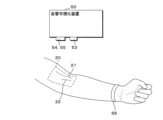
- FIG. 1 is a diagram illustrating an example of the configuration of a blood vessel visualization device according to an embodiment of the present invention.
- 1A to 1C are diagrams illustrating a first example of a method for implementing a blood vessel visualization device.
- 13 is a diagram showing a second example of a method for implementing the blood vessel visualization device.
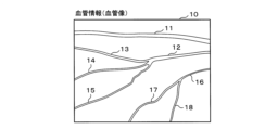
- FIG. 13 is a diagram showing an example of blood vessel information (blood vessel image).
- FIG. 13 is a diagram showing an example of vascular parameters.
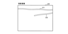
- FIG. 13 is a diagram showing an example of a projection image of a blood vessel.
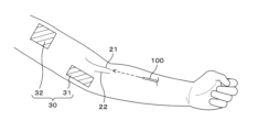
- FIG. 4 is a diagram showing an example of a projection area of a virtual operation unit.
- FIG. 13 is a diagram illustrating an example of a method for calculating a puncture vessel priority and a projection avoidance vessel priority.
- FIG. 2 is a diagram illustrating an example of a virtual operation unit.
- FIG. 2 is a diagram illustrating an example of a virtual operation unit.
- FIG. 2 is a diagram illustrating an example of a virtual operation unit.
- FIG. 13 is a diagram showing an example of a virtual operation panel being projected.
- 11A and 11B are diagrams illustrating an example of an indirect operation on a virtual operation unit.
- FIG. 1 is a diagram showing an example of the configuration of a vascular visualization system including a vascular access device.
- FIG. 2 is a diagram showing an example of a processing procedure performed by the blood vessel visualization device.
- FIG. 1 is a diagram showing an example of the configuration of a blood vessel visualization device 50 of this embodiment.
- the blood vessel visualization device 50 includes a control unit 51 that controls the entire device, a communication unit 52, a light source unit 53, a camera unit 54, a projection unit 55, a sensor unit 56, a memory 57, an image processing unit 58, and a storage unit 59.
- the control unit 51 is configured by incorporating the required number of CPUs (Central Processing Units), MPUs (Micro-Processing Units), GPUs (Graphics Processing Units), etc.
- the control unit 51 may also be configured by combining DSPs (Digital Signal Processors), FPGAs (Field-Programmable Gate Arrays), etc.
- the communication unit 52 may, for example, include a communication module and may have a communication function (either wireless communication or wired communication, or both) with an external device (not shown).
- the light source unit 53 includes, for example, one or more LED light sources that emit near-infrared light of 700 to 2500 nm.
- the light source unit 53 includes, for example, one or more LED light sources that emit visible light of 380 to 770 nm.
- the amount of light from the light source unit 53 can be adjusted based on the control of the control unit 51.
- the light source unit 53 irradiates the aforementioned light to a predetermined site (site to be punctured) of the subject (subject to be punctured).
- the camera unit 54 can capture near-infrared light of, for example, 700 to 2500 nm.
- the camera unit 54 can also capture visible light of, for example, 380 to 770 nm.
- the camera unit 54 can also capture far-infrared light of, for example, 2500 nm or more.
- the camera unit 54 may be configured as a single unit (integrated) camera capable of capturing near-infrared light, visible light, and far-infrared light, or as separate units. If the camera unit 54 is a single unit, a filter or the like may be used to switch between near-infrared light, visible light, and far-infrared light. If the camera unit 54 is a separate unit, it is preferable that the cameras be able to capture images coaxially by using a half mirror or the like.
- the camera unit 54 is configured to photograph a specific part of the subject from a position an appropriate distance away from the specific part.
- the position of the light source unit 53 is near the camera unit 54 and may be arranged on the same side of the specific part as the camera unit 54, or on the opposite side of the specific part from the camera unit 54 (i.e., arranged so that the specific part is sandwiched between the camera unit 54 and the light source unit 53), or the light source unit 53 may be arranged on both sides of the specific part so as to sandwich the specific part.
- the projection unit 55 includes a projector capable of projecting a projected image of blood vessels and a virtual operation unit (digital object) for operating the projected image onto desired locations such as human skin or the surface of a desk.
- a projector capable of projecting a projected image of blood vessels
- a virtual operation unit digital object
- the projector that projects the projected image and the projector that projects the virtual operation unit may be the same or different.
- the projected image and the virtual operation unit will be described in detail below.
- the camera unit 54 also captures an image of the operation of the puncture operator (healthcare worker) on the virtual operation unit.
- the control unit 51 can identify the content of the operation of the puncture operator based on the image captured by the camera unit 54. For example, it can identify which operation item of the virtual operation unit the operation is for based on the movement of the puncture operator's fingers or hand, the relative position with respect to the operated object in the virtual operation unit, and the like. Also, a learning model (one learning model of the learning model unit 61) that has been trained to output the expected operation content when an image of a finger or hand including the virtual operation unit is input may be used.
- the sensor unit 56 detects, for example, the movements of the fingers or hands of a puncture operator such as a medical professional, and detects operations on the virtual operation unit.
- the sensor unit 56 includes, for example, at least one of an acoustic sensor, a vibration sensor, a depth sensor, an acceleration sensor, and an electric potential sensor.
- Acoustic sensors and vibration sensors can detect vibrations based on arm or palm movements (such as vibrations caused by contact or when flicking), and can determine the flicking position and method (i.e., the distinction between the operation of the puncture operator) based on the shape and strength of the detected vibration waveform.
- the depth sensor works by having the subject wear a ring with a depth sensor on their wrist, shining infrared light onto the target area (e.g., a finger, arm, etc.), measuring the time from when the light is irradiated until the reflected light returns, and can determine the position (coordinates) of the target area (e.g., a finger) and any changes in the target area (e.g., an arm) based on the measured time.
- the target area e.g., a finger, arm, etc.
- the acceleration sensor can, for example, detect the acceleration of the puncture operator's finger movements by having the puncture operator wear a ring equipped with an acceleration sensor, and calculate the finger movements (magnitude, number of movements, direction of movement, etc.) based on the detected acceleration to determine the finger movements.
- the potential sensor can, for example, be equipped with a ring with a potential sensor attached that is worn by the puncture operator, detect the potential difference when skin contact occurs, and determine whether contact has occurred, the location of contact, etc. based on the detected potential difference.
- Memory 57 can be composed of semiconductor memory such as SRAM (Static Random Access Memory), DRAM (Dynamic Random Access Memory), flash memory, etc.
- SRAM Static Random Access Memory
- DRAM Dynamic Random Access Memory
- flash memory etc.
- the image processing unit 58 detects blood vessel images of blood vessels contained in a specific part of the subject based on an image obtained by photographing the specific part of the subject with the camera unit 54, and detects blood vessel information of the blood vessels.
- the image processing unit 58 also detects a projectable area of the virtual operation unit based on an image obtained by photographing the specific part of the subject with the camera unit 54.
- the image processing unit 58 also detects direct or indirect operation of the virtual operation unit by the puncture operator.
- a direct operation of the virtual operation unit means an operation by directly touching the projected virtual operation unit
- an indirect operation means an operation indirectly by operating the virtual operation unit by operating an operation object other than the virtual operation unit.
- the storage unit 59 can be configured, for example, with a hard disk or semiconductor memory, and can store a computer program (program product) 60, a learning model unit 61, and required information.
- Computer program 60 is a computer program (application) that runs on blood vessel visualization device 50, and is deployed in memory 57 and executed by control unit 51. In other words, processing by control unit 51 is also processing by computer program 60.
- Computer program 60 may be stored in memory unit 59 after being read by a recording medium reading unit (not shown) from recording medium M (e.g., an optically readable disk storage medium such as a CD-ROM), or it may be downloaded from an external device via communication unit 52 and installed. Details of learning model unit 61 will be described later.
- FIG. 2 is a diagram showing a first example of a method for mounting the blood vessel visualization device 50.
- the arm forearm
- the blood vessel visualization device 50 is fixed to a support such as a stand so that it is placed at a suitable distance from the subject's arm.
- the blood vessel visualization device 50 may be movably attached to the support so that the light source unit 53, the camera unit 54, and the projection unit 55 are oriented in the optimal direction.
- the sensor unit 56 is, for example, a depth sensor, but in the case of other sensors, the sensor unit 56 may be provided in the blood vessel visualization device 50 or may be attached to the finger of the puncture operator. In addition, when detecting the movement of the finger or hand of the puncture operator based on the image captured by the camera unit 54, the sensor unit 56 may not be provided.
- a blood vessel projection image 20 is projected onto the subject's arm by the projection unit 55.
- two blood vessel regions 21 and 22 are displayed in the projection image 20.
- FIG. 3 is a schematic diagram showing a second example of a method for mounting the blood vessel visualization device 50.
- a belt 70 is worn on the subject's upper arm, and the blood vessel visualization device 50 is mounted on the belt 70.
- a light source unit 53, a camera unit 54, and a projection unit 55 are attached to appropriate positions on the belt 70 so that they face in optimal directions.
- a blood vessel projection image 20 is projected by the projection unit 55 onto the subject's arm, and two blood vessel regions 21, 22 are displayed in the projection image 20.
- FIG. 4 is a diagram showing an example of blood vessel information (blood vessel image).
- the control unit 51 irradiates near-infrared light from the light source unit 53 towards the subject's arm, and obtains an image by photographing the arm irradiated with the near-infrared light using the camera unit 54.
- Hemoglobin contained in blood has the property of absorbing near-infrared light, and by utilizing this property, the parts of the obtained image that correspond to blood vessels appear dark, and parts other than the blood vessels appear brighter than the parts that correspond to the blood vessels.
- the image processing unit 58 performs edge detection and binarization on the obtained image to distinguish between blood vessels and non-blood vessels and obtain blood vessel information (blood vessel image).
- blood vessel information (blood vessel image) 10 includes blood vessels 11, 12, 13, 14, 15, 16, 17, and 18.
- control unit 51 can detect vascular information of blood vessels contained in a specific part of a subject based on an image of the specific part.
- Detection of vascular information is not limited to edge detection or binarization processing in the image processing unit 58.
- a learning model one learning model in the learning model unit 61
- a thermal camera may be used in combination, which irradiates far-infrared light from the light source unit 53 and detects the temperature of the skin surface irradiated with the far-infrared light using the camera unit 54.
- FIG. 5 shows an example of vascular parameters.
- the vascular parameters can be used when selecting a blood vessel to be punctured (e.g., selecting the best blood vessel to be punctured or determining the priority of blood vessels to be punctured), and can also be used when selecting the projection area of the virtual operation unit while avoiding the blood vessel area included in the projection image of the blood vessel.
- the vascular parameters include at least one of the length, thickness, depth, straightness, and running direction of the blood vessel.
- the length of a blood vessel is the distance from one end of the blood vessel to the other. In general, the longer and more straight the blood vessel, the easier it is to puncture it.
- the thickness of a blood vessel is the distance in the direction perpendicular to the length of the blood vessel (the width of the blood vessel). In general, the thicker the blood vessel, the easier it is to puncture it.
- the depth of a blood vessel is the distance from the surface of the skin to the blood vessel. When light is irradiated from the light source unit 53, the depth of the blood vessel can be calculated by measuring the ultrasound generated in the blood vessel that selectively absorbs the energy of the light. In general, the shallower the blood vessel is, the easier it is to puncture it.
- the straightness of a blood vessel can be calculated by thinning the blood vessel image to generate an approximation line, and using the coefficient of determination (R2) that indicates how well the generated approximation line matches a straight line. The closer the coefficient of determination is to 1, the higher the straightness and the easier it is to puncture.
- the running direction of a blood vessel is the angle between the direction of the approximation line of the blood vessel described above and a specific direction.
- the specific direction can be, for example, the direction of the puncture needle when the puncture operator punctures the blood vessel.
- the puncture needle includes both an inner needle and an outer needle.
- the inner needle is made of metal and is used to insert into a blood vessel.
- the outer needle is inserted into the blood vessel using, for example, a soft plastic catheter, and then the inner needle is removed, leaving only the outer needle in the blood vessel.
- the length, thickness, depth, straightness, and running direction are represented by L11, T11, D11, S11, and R11 for the sake of convenience. The same applies to the other blood vessels 12 to 18.
- control unit 51 can calculate blood vessel parameters including at least one of the blood vessel length, thickness, depth, straightness, and running direction based on the detected blood vessel information.
- FIG. 6 is a diagram showing an example of a blood vessel projection image 20.
- the values of the blood vessel parameters (length, thickness, depth, straightness, and running direction of the blood vessel) of each of the blood vessels 11 to 18 shown in FIG. 4 are compared with the respective blood vessel parameter thresholds to select a blood vessel suitable for puncture.
- blood vessels 11 and 12 are selected from blood vessels 11 to 18, and a projection image 20 is generated based on the blood vessel information of blood vessels 11 and 12.
- Blood vessel regions 21 and 22 in the projection image 20 correspond to blood vessels 11 and 12 in the blood vessel information 10.
- the blood vessel regions 21 and 22 can be generated by simplifying the shape of the actual blood vessels 11 and 12.
- the outer diameter shape of the blood vessel can be alternatively displayed as a straight line or the like within the blood vessel and within a range not exceeding the outer diameter shape.
- control unit 51 can generate a projection image of the blood vessels based on the detected blood vessel information.
- the control unit 51 detects the projectable area of the virtual operation unit, and can project the virtual operation unit onto the detected projectable area excluding the blood vessel area of the projection image. By positioning the virtual operation unit in an area excluding the blood vessel area, it does not interfere with puncture.
- the projectable area of the virtual operation unit can be determined, for example, by the following method. (1) A projectable area is detected by performing image processing such as edge detection on an image captured by the camera unit 54. In this case, light may be emitted from the light source unit 53 or from the projection unit 55. (2) Far-infrared light may be emitted from the light source unit 53 and photographed by the camera unit 54 (using a thermal camera in combination).
- a learning model (one learning model in the learning model unit 61) that has been trained to output a projectable area when an image of an arm or its surroundings is input may be used.
- a method in which markers for defining the projectable area are attached to a plurality of required locations on the arm, and the area surrounded by the markers is detected as the projectable area may be used.
- FIG. 7 is a diagram showing an example of the projection area 30 of the virtual operation unit.
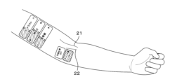
- a projection image including blood vessel areas 21 and 22 is projected and displayed on the skin of the arm.
- the puncture operator can insert the puncture needle 100 by referring to the blood vessel area in the projected image.
- blood vessel area 21 is selected as the blood vessel to be punctured.
- the control unit 51 can project a virtual operation unit for operating the projection image in an area (projection area 30) excluding the vascular areas 21 and 22 included in the projection image.
- the projection area 30 of the virtual operation unit is divided into two projection areas 31 and 32 and projected. There may be one or more projection areas.
- the virtual operation unit may be projected within the vascular area. For example, if a specific vascular area can be visually confirmed on the arm of the person to be punctured, the puncture operator can directly touch the specific vascular area to be visualized and manually or semi-automatically select the projection image of the blood vessel to be projected. Furthermore, the use of the virtual operation unit can prevent infection.
- the control unit 51 can identify a recommended projection area for the virtual operation unit and project the virtual operation unit into the identified recommended projection area.
- the recommended projection area is an area that does not overlap at least the blood vessel area of the projected image. This allows the virtual operation unit to be projected into the optimal position that does not interfere with the puncture.
- the recommended projection area is an area that does not overlap with the blood vessel area of the projection image and is an area where the fingers or hands of the puncture operator are not present.
- the control unit 51 can detect the movement range of the arm, including the fingers of the puncture operator, at a specified site and specify the recommended projection area by excluding the detected movement range. This allows the virtual operation unit to be projected at an optimal position that does not interfere with the puncture. Also, puncture can be performed with less discomfort (for example, the projection image is not reflected on the arm, including the fingers of the puncture operator).
- the recommended projection area is an area where the fingers or hands of the puncture operator are not present and is an area closer to the puncture operator (an area closer to the puncture operator). By positioning the recommended projection area closer to the puncture operator and projecting the virtual operation unit, the puncture operator can easily operate the virtual operation unit and can operate the buttons smoothly.
- the blood vessel to be punctured and the blood vessel to avoid projecting the virtual control part can be selected based on the blood vessel parameters calculated from the blood vessel information described above.
- Equation 1 in Figure 8 shows an example of a method for calculating the puncture vessel priority and the projection avoidance vessel priority.
- the weighting coefficients that weight the values of the vessel parameters, namely the length, thickness, depth, straightness, and running direction, are w1, w2, w3, w4, and w5.
- w1 to w5 can also be 0.
- the puncture vessel priority W1 of a vessel can be calculated from the vessel information of the vessel contained in the specified portion.
- the vessel with the largest puncture vessel priority W1 value can be determined as the optimal vessel for puncture.
- the control unit 51 can identify the optimal vascular region for puncturing from among the vascular regions included in the projected image based on the vascular parameters, and project the virtual operation unit onto the region excluding the optimal vascular region for puncturing. By displaying blood vessels suitable for puncturing, blood vessels can be evaluated quickly and accurately.
- training data including the value of a vascular parameter and the puncture success rate or success or failure of puncture for a blood vessel having the vascular parameter of that value may be collected, and a learning model (one learning model of the learning model unit 61) may be used that has been trained to output the puncture success rate or success or failure of puncture when the value of the vascular parameter is input using the collected training data.
- a learning model one learning model of the learning model unit 61
- K is a constant.
- the control unit 51 calculates the projection avoidance priority of the blood vessel region included in the projection image by weighting with the calculated blood vessel parameters, and can select the projection region onto which the virtual operation unit is projected based on the calculated priority. By weighting, even if the projection range is narrow, the virtual operation unit can be projected so as not to interfere with blood vessels suitable for puncture.
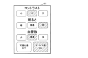
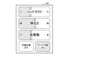
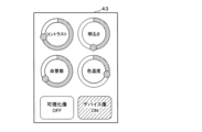
- FIGS. 9A to 9C are diagrams showing an example of a virtual operation unit. Items that can be operated using the virtual operation unit include, for example, the contrast and brightness of the projected image of blood vessels, the number of blood vessels to be displayed, visualization image ON/OFF, device image ON/OFF, and blood vessel color temperature, but the items that can be operated are not limited to the example in FIG. 9.
- the operation button for the operation item in the virtual operation unit can be tapped.
- the slider bar for the operation item in the virtual operation unit can be slid.
- FIG. 9C the ring button for the operation item in the virtual operation unit can be rotated.
- the visualization image OFF is an operation button for stopping the projection of the projected image (so that it is not displayed).
- the device image ON is an operation button for turning on the display of the tip position of the puncture needle of the vascular access device.
- Vascular access devices include products such as peripheral arterial and venous indwelling needles, dialysis indwelling needles, PICCs, midlines, and CV catheters. Additionally, when the device image is ON, the size, color, etc. of the area displayed to indicate the tip position of the puncture needle of the vascular access device (for example, surrounding the position with a circular mark) may be changed.
- buttons for selecting whether to project only the optimal blood vessels for puncture or all blood vessels may be projected.
- Operation buttons for adjusting the edge and brightness of blood vessels, etc. may also be projected.
- FIG. 10 is a diagram showing an example of the virtual operation unit during projection.
- the projection area is divided into two areas. Of the two projection areas, the projection area closer to the puncture operator can be used to place high priority items among the operation items of the virtual operation unit.
- "Visualization image OFF" and "Device image ON” are projected from among the operation items of the virtual operation unit onto the projection area closer to the puncture operator, and the remaining operation items of the virtual operation unit (contrast, brightness, number of blood vessels) are projected onto the projection area farther from the puncture operator.
- the virtual operation unit is projected onto the surface of the subject's arm, but this is not limited to this.
- the virtual operation unit may be projected onto the surface of a table or desk on which the subject's arm is placed, in a position close to the puncture operator.
- the puncture operator can change the display of the projection image according to the operation item by operating the operation items of the virtual operation unit shown in Figures 9 and 10. For example, by operating "Visualization Image OFF", the projection of the projection image of the blood vessel can be stopped. Furthermore, by operating “Device Image ON”, the position of the blood vessel access device can be displayed in the projection image. Furthermore, by operating "Contrast”, “Brightness”, and “Number of Blood Vessels", the contrast of the projection image, the brightness of the projection image, and the number of blood vessels in the projection image can be changed, respectively.
- control unit 51 can detect a direct operation on the virtual operation unit and change the display of the projected image in accordance with the detected operation.
- a direct operation refers to a case where an operation is performed directly on the virtual operation unit.
- the control unit 51 can also select an operated object of the virtual operation unit according to the priority of multiple operated objects included in the virtual operation unit, and project the selected operated object. Even if the projection range is narrow, the virtual operation unit can be projected while maintaining ease of use.
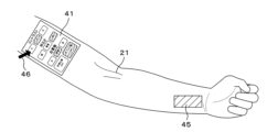
- FIG. 11 is a diagram showing an example of indirect operation on the virtual operation unit.
- a virtual operation unit 41 is projected onto the upper arm of the subject.
- An indirect operation area 45 is also projected onto the subject's arm.
- a pointer 46 on the virtual operation unit 41 moves in conjunction with the indirect operation area 45, allowing the puncture operator to select the desired operation item.
- the puncture operator taps his/her finger on the indirect operation area 45, the puncture operator can indirectly operate the operation items on the virtual operation unit 41.
- the indirect operation area 45 is projected onto the surface of the subject's arm, but this is not limited to this.
- the indirect operation area 45 may be projected onto the surface of a table or desk on which the subject's arm is placed, at a position close to the puncture operator.
- control unit 51 can detect indirect operations on the virtual operation unit and change the display of the projected image in response to the detected operations.
- Indirect operations refer to the case where the virtual operation unit is indirectly operated via an operation unit separate from the virtual operation unit.
- the virtual operation unit can be projected in an optimal state for puncture.
- Figure 12 is a diagram showing an example of the configuration of a blood vessel visualization system equipped with a blood vessel access device.
- a light source unit that emits near-infrared light and a light receiving unit are arranged to sandwich the area to be visualized. Near-infrared light is irradiated from the light source unit, and the light that passes through the area to be visualized is received by the light receiving unit, generating and projecting a projection image of the blood vessel.
- the position of the tip of the puncture needle of the vascular access device is detected, and the detected position of the tip of the puncture needle is displayed on the projection image. In this case, when the light emitting unit at the tip of the puncture needle reaches the blood vessel, the light from the light emitting unit goes out, allowing visual confirmation that the puncture needle has secured the blood vessel.
- Vascular access devices include, for example, peripheral arterial and venous indwelling needles, dialysis indwelling needles, PICCs, midlines, and CV catheters, and the catheter tip or inner needle tip is designed to emit, fluoresce, or reflect near-infrared light.
- the light source unit and the camera unit 54 may be placed on the same side of the area to be visualized, and the reflected light of the near-infrared light irradiated from the light source unit may be detected. Also, the camera unit 54 may be provided in addition to the light receiving unit.
- control unit 51 detects the position of the blood vessel access device to be inserted into a specific area based on an image of the specific area, and can project a virtual operation unit onto an area other than the detected position. By detecting the position of the blood vessel access device, the virtual operation unit can be projected without interfering with the insertion.
- the medical staff can evaluate the puncture vessel with the assistance of the vascular visualization device 50 and make the final decision to perform the puncture, which is expected to enable quick button operations and smooth puncture.
- FIG. 13 is a diagram showing an example of a processing procedure by the blood vessel visualization device 50.
- the control unit 51 acting as the subject of the processing.
- the control unit 51 irradiates a predetermined part of the subject with a predetermined light and photographs the predetermined part (S11).
- the predetermined light is, for example, near-infrared light.
- the predetermined light may also include visible light and far-infrared light.
- the control unit 51 acquires blood vessel information of the blood vessels contained in the predetermined part (S12), and generates a projection image of the blood vessels based on the acquired blood vessel information (S13). For blood vessel information, see FIG. 4. For the projection image, see FIG. 6.
- the control unit 51 detects the projectable area of the virtual operation unit (S14), projects a projection image of the blood vessel, and projects the virtual operation unit onto the projectable area excluding the blood vessel area included in the projection image (S15). Note that if an optimal blood vessel has been selected, the virtual operation unit may be projected onto the blood vessel area, but not onto the optimal blood vessel area. Also, if the priority of the blood vessel to be punctured is calculated and multiple blood vessels to be punctured are selected according to the priority, the virtual operation unit may be projected onto the blood vessel area, but not onto the selected blood vessel area.
- the control unit 51 determines whether or not there is an operation (direct operation or indirect operation) on the virtual operation unit (S16), and if there is an operation (YES in S16), changes the display of the projected image according to the operation (S17), and determines whether or not to end the process (S18). If there is no operation on the virtual operation unit (NO in S16), the control unit 51 performs the process of step S18. If the process is not to be ended (NO in S18), the control unit 51 continues the process from step S16 onwards, and if the process is to be ended (YES in S18), ends the process.
- an operable virtual operation unit (operation buttons, icons, bars, etc. displayed by projection) can be placed in an appropriate position close to the puncture site and that does not interfere with the puncture (for example, it can be the surface of the skin at the specified site, or the surface of a stand or table on which the specified site is placed), so there is no need to operate device buttons located away from the puncture site, and since actual device buttons are not required, there is no need to worry about infection via device buttons. This makes it possible to assist in easy puncture without operating device buttons.
Landscapes
- Health & Medical Sciences (AREA)
- Life Sciences & Earth Sciences (AREA)
- Engineering & Computer Science (AREA)
- Physics & Mathematics (AREA)
- General Health & Medical Sciences (AREA)
- Pathology (AREA)
- Biomedical Technology (AREA)
- Molecular Biology (AREA)
- Veterinary Medicine (AREA)
- Medical Informatics (AREA)
- Public Health (AREA)
- Surgery (AREA)
- Heart & Thoracic Surgery (AREA)
- Animal Behavior & Ethology (AREA)
- Biophysics (AREA)
- Hematology (AREA)
- Pain & Pain Management (AREA)
- Dermatology (AREA)
- General Physics & Mathematics (AREA)
- Theoretical Computer Science (AREA)
- Analytical Chemistry (AREA)
- Immunology (AREA)
- Biochemistry (AREA)
- Chemical & Material Sciences (AREA)
- Dentistry (AREA)
- Oral & Maxillofacial Surgery (AREA)
- Computer Hardware Design (AREA)
- Spectroscopy & Molecular Physics (AREA)
- Mathematical Physics (AREA)
- Vascular Medicine (AREA)
- Infusion, Injection, And Reservoir Apparatuses (AREA)
- Measurement Of The Respiration, Hearing Ability, Form, And Blood Characteristics Of Living Organisms (AREA)
Priority Applications (2)
| Application Number | Priority Date | Filing Date | Title |
|---|---|---|---|
| JP2025548578A JPWO2025069767A1 (cg-RX-API-DMAC7.html) | 2023-09-25 | 2024-08-15 | |
| US19/572,174 US20260207100A1 (en) | 2023-09-25 | 2026-03-19 | Blood vessel visualization device, blood vessel visualization system, and blood vessel visualization method |
Applications Claiming Priority (2)
| Application Number | Priority Date | Filing Date | Title |
|---|---|---|---|
| JP2023161607 | 2023-09-25 | ||
| JP2023-161607 | 2023-09-25 |
Related Child Applications (1)
| Application Number | Title | Priority Date | Filing Date |
|---|---|---|---|
| US19/572,174 Continuation US20260207100A1 (en) | 2023-09-25 | 2026-03-19 | Blood vessel visualization device, blood vessel visualization system, and blood vessel visualization method |
Publications (1)
| Publication Number | Publication Date |
|---|---|
| WO2025069767A1 true WO2025069767A1 (ja) | 2025-04-03 |
Family
ID=95203636
Family Applications (1)
| Application Number | Title | Priority Date | Filing Date |
|---|---|---|---|
| PCT/JP2024/029103 Ceased WO2025069767A1 (ja) | 2023-09-25 | 2024-08-15 | コンピュータプログラム、血管可視化装置、血管可視化システム及び血管可視化方法 |
Country Status (3)
| Country | Link |
|---|---|
| US (1) | US20260207100A1 (cg-RX-API-DMAC7.html) |
| JP (1) | JPWO2025069767A1 (cg-RX-API-DMAC7.html) |
| WO (1) | WO2025069767A1 (cg-RX-API-DMAC7.html) |
Citations (7)
| Publication number | Priority date | Publication date | Assignee | Title |
|---|---|---|---|---|
| JP2009523038A (ja) * | 2006-01-10 | 2009-06-18 | アキュベイン エルエルシー | 小型静脈像エンハンサ |
| US20130069940A1 (en) * | 2011-09-21 | 2013-03-21 | University Of South Florida (A Florida Non-Profit Corporation) | Systems And Methods For Projecting Images Onto An Object |
| US20150193978A1 (en) * | 2014-01-05 | 2015-07-09 | Hong Kong Applied Science And Technology Research Institute Co. Ltd. | Image projector |
| WO2017056775A1 (ja) * | 2015-09-28 | 2017-04-06 | 富士フイルム株式会社 | プロジェクションマッピング装置 |
| JP2017533487A (ja) * | 2014-08-15 | 2017-11-09 | ザ・ユニバーシティ・オブ・ブリティッシュ・コロンビア | 医療処置の実施と医療関連情報のアクセスおよび/または操作のための方法およびシステム |
| WO2018061383A1 (ja) * | 2016-09-28 | 2018-04-05 | 富士フイルム株式会社 | 3次元画像投影装置および方法並びに3次元画像投影制御プログラム |
| CN112732158A (zh) * | 2020-12-31 | 2021-04-30 | 维沃移动通信有限公司 | 可穿戴设备及可穿戴设备的控制方法 |
-
2024
- 2024-08-15 JP JP2025548578A patent/JPWO2025069767A1/ja active Pending
- 2024-08-15 WO PCT/JP2024/029103 patent/WO2025069767A1/ja not_active Ceased
-
2026
- 2026-03-19 US US19/572,174 patent/US20260207100A1/en active Pending
Patent Citations (7)
| Publication number | Priority date | Publication date | Assignee | Title |
|---|---|---|---|---|
| JP2009523038A (ja) * | 2006-01-10 | 2009-06-18 | アキュベイン エルエルシー | 小型静脈像エンハンサ |
| US20130069940A1 (en) * | 2011-09-21 | 2013-03-21 | University Of South Florida (A Florida Non-Profit Corporation) | Systems And Methods For Projecting Images Onto An Object |
| US20150193978A1 (en) * | 2014-01-05 | 2015-07-09 | Hong Kong Applied Science And Technology Research Institute Co. Ltd. | Image projector |
| JP2017533487A (ja) * | 2014-08-15 | 2017-11-09 | ザ・ユニバーシティ・オブ・ブリティッシュ・コロンビア | 医療処置の実施と医療関連情報のアクセスおよび/または操作のための方法およびシステム |
| WO2017056775A1 (ja) * | 2015-09-28 | 2017-04-06 | 富士フイルム株式会社 | プロジェクションマッピング装置 |
| WO2018061383A1 (ja) * | 2016-09-28 | 2018-04-05 | 富士フイルム株式会社 | 3次元画像投影装置および方法並びに3次元画像投影制御プログラム |
| CN112732158A (zh) * | 2020-12-31 | 2021-04-30 | 维沃移动通信有限公司 | 可穿戴设备及可穿戴设备的控制方法 |
Also Published As
| Publication number | Publication date |
|---|---|
| JPWO2025069767A1 (cg-RX-API-DMAC7.html) | 2025-04-03 |
| US20260207100A1 (en) | 2026-07-23 |
Similar Documents
| Publication | Publication Date | Title |
|---|---|---|
| JP4517004B2 (ja) | 注射針誘導装置 | |
| CA2988683C (en) | Apparatus and method for inspecting skin lesions | |
| US10492873B2 (en) | Medical spatial orientation system | |
| US20100013764A1 (en) | Devices for Controlling Computers and Devices | |
| US20200005026A1 (en) | Gesture-based casting and manipulation of virtual content in artificial-reality environments | |
| CN110225719B (zh) | 用于辐射剂量监测的增强现实 | |
| US10387013B2 (en) | Systems and methods for controlled single touch zoom | |
| CA2648865A1 (en) | Systems and methods for wound area management | |
| JP7297796B2 (ja) | グラフィカルユーザインタフェースを有する手術用器具を利用するためのシステム及び方法 | |
| EP3380031A1 (en) | Method and system for interacting with medical information | |
| JP2021524096A (ja) | 足制御型カーソル | |
| JP7209128B2 (ja) | スマートグラスの視線トラッキングシステムおよびその方法 | |
| US12481399B2 (en) | Finger tapping measurement processing terminal, system, method, and computer program | |
| JP2023512351A (ja) | 身体の目的ターゲットの位置確認方法 | |
| JP6747172B2 (ja) | 診断支援装置、診断支援方法、及びコンピュータプログラム | |
| NL2034443B1 (en) | Ultrasonic display system and method based on augmented reality | |
| CN111796317A (zh) | 吸收辐射量管理装置及吸收辐射量管理方法 | |
| JP7610720B2 (ja) | 手指の動きを計測処理する計測処理端末、方法およびコンピュータプログラム | |
| JP6310255B2 (ja) | オプションを提示するための方法及び装置 | |
| Opromolla et al. | A usability study of a gesture recognition system applied during the surgical procedures | |
| JP2014198271A (ja) | X線撮影装置 | |
| KR20210102658A (ko) | 시선, 제스쳐, 또는 음성을 이용한 비접촉 무균 조작 시스템 | |
| CN112397189A (zh) | 一种医用导引装置及其使用方法 | |
| CN103908293B (zh) | 用于测量医学图像的医学成像系统和方法 | |
| Stuij | Usability evaluation of the kinect in aiding surgeon computer interaction |
Legal Events
| Date | Code | Title | Description |
|---|---|---|---|
| 121 | Ep: the epo has been informed by wipo that ep was designated in this application |
Ref document number: 24871569 Country of ref document: EP Kind code of ref document: A1 |
|
| ENP | Entry into the national phase |
Ref document number: 2025548578 Country of ref document: JP Kind code of ref document: A |
|
| WWE | Wipo information: entry into national phase |
Ref document number: 2025548578 Country of ref document: JP |
|
| NENP | Non-entry into the national phase |
Ref country code: DE |