WO2025062550A1 - 作業管理装置、作業管理システム、および、作業管理方法 - Google Patents
作業管理装置、作業管理システム、および、作業管理方法 Download PDFInfo
- Publication number
- WO2025062550A1 WO2025062550A1 PCT/JP2023/034205 JP2023034205W WO2025062550A1 WO 2025062550 A1 WO2025062550 A1 WO 2025062550A1 JP 2023034205 W JP2023034205 W JP 2023034205W WO 2025062550 A1 WO2025062550 A1 WO 2025062550A1
- Authority
- WO
- WIPO (PCT)
- Prior art keywords
- area
- person
- data
- posture
- recognized
- Prior art date
- Legal status (The legal status is an assumption and is not a legal conclusion. Google has not performed a legal analysis and makes no representation as to the accuracy of the status listed.)
- Pending
Links
Images


















Classifications
-
- G—PHYSICS
- G06—COMPUTING OR CALCULATING; COUNTING
- G06T—IMAGE DATA PROCESSING OR GENERATION, IN GENERAL
- G06T7/00—Image analysis
-
- G—PHYSICS
- G06—COMPUTING OR CALCULATING; COUNTING
- G06T—IMAGE DATA PROCESSING OR GENERATION, IN GENERAL
- G06T7/00—Image analysis
- G06T7/70—Determining position or orientation of objects or cameras
Definitions
- the present invention relates to a work management device, a work management system, and a work management method.
- Patent Document 1 describes an invention in which a motion information registration unit identifies the motion content indicated by motion information, which is skeletal information similar to the target information extracted by a skeletal extraction unit, as the motion content being performed by the target person.
- FIG. 13 is a flowchart showing a model definition by a background definition unit.
- FIG. 2 is a diagram showing image data that is a target of model definition.
- FIG. 12 is a diagram showing an example of an area model generated from the image data of FIG. 11 .
- FIG. 12 is a diagram showing an example of a background model generated from the image data of FIG. 11 .
- 13 is a flowchart showing model definition by a posture learning unit.
- FIG. 15 is a diagram showing a GUI screen in a learning process of the orientation detection unit in FIG. 14 .
- FIG. 15 is a diagram showing a posture model generated as a result of a learning process of the posture detection unit of FIG. 14 .
- FIG. 13 is a diagram showing a procedure model that is a result of learning by a procedure learning unit.
- 13 is a flowchart showing a main process of an analysis unit.
- 13 is a flowchart showing a subroutine process of the area detection unit.
- FIG. 20 is a diagram showing the result of the processing in FIG. 19 when both hands are recognized in the "part removal area.”
- FIG. 20 is a diagram showing the result of the processing in FIG. 19 when both hands are recognized in the “finished product storage area.”
- 13 is a flowchart showing a subroutine process of the attitude detection unit.
- FIG. 23 is a diagram showing image data used in the processing of FIG. 22.
- FIG. 23 is a diagram of posture data showing inferred labels (posture labels) for the image data of FIG. 22.
- FIG. 13 is a flowchart showing a subroutine process of the background detection unit.
- FIG. 26 is a diagram showing a state in which the driver has recognized an unused state as a result of the processing in FIG. 25.
- FIG. 26 is a diagram showing a state where the driver recognizes the vehicle being used as a result of the processing shown in FIG. 25.
- 11 is a diagram showing an example of procedure data output by a procedure detection unit;
- FIG. FIG. 30 is a diagram showing a screen in which the procedure data of FIG. 28 is displayed in a Gantt chart format.
- FIG. 11 is a configuration diagram of a work management device according to a second embodiment.
- FIG. 11 is a diagram showing an example of a video to be input to the work management device.
- FIG. 11 is a diagram showing an example of skeletal data extracted from frames of a video to be input to the task management device;
- FIG. 1 is a diagram showing an example of image data obtained by cutting out a portion to be recognized from image data to be input to a work management device;
- FIG. 4 is a diagram showing an example of skeletal data.
- FIG. 13 is a diagram illustrating an example of a region model. 1 is a time chart showing the work content of a worker. 1 is a time chart showing the work content of a worker. 1 is a time chart showing the work content of a worker. 1 is a time chart showing the work content of a worker. 1 is a time chart showing the work content of a worker. 4 is a time chart showing the working posture determined by the work management device and the work content of the worker.
- FIG. 13 is a flowchart showing a work management process.
- 13 is a flowchart showing a work management process.
- 13 is a flowchart showing a process of associating a working posture with a driver.
- FIG. 13 is a diagram showing a real-time screen displayed by the work management device.
- FIG. 13 is a diagram showing a history data screen displayed by the work management device.
- FIG. 13 is a diagram showing a recognition report screen displayed by the work management device.
- Each of these devices in the work management system is connected by a network such as Ethernet (registered trademark), USB (Universal Serial Bus), or any other appropriate device that can be used as a hardware interface.
- a network such as Ethernet (registered trademark), USB (Universal Serial Bus), or any other appropriate device that can be used as a hardware interface.
- each device in the work management system may be configured as a standalone device, or may be realized by executing software on a computer system such as the work management device 2.
- the video camera 1 captures images of a worker as a subject.
- the video recorder 13 records the video captured by the video camera 1.
- the input/output device 14 includes a graphic display and a mouse, and displays information to a user such as a worker and receives instructions from the user.
- the monitor 31, the storage device 32, and the application device 33 are output destinations of the analysis results of the work management device 2 (see FIG. 9 for details).
- the work management device 2 is, for example, a computer system such as an on-premises server or a cloud server.
- the work management device 2 is configured as a computer having a CPU (Central Processing Unit), memory, a storage means (storage unit) such as a hard disk, and a network interface.
- This computer operates a control unit (control means) made up of each processing unit by the CPU executing a program loaded onto the memory.
- the work management device 2 executes a program on a computer system to configure an image processing unit 202, a skeleton extraction unit 21, a model generation unit 211, an analysis unit 23, and an output unit 28.
- Each of these configured processing units accesses data (model data 212, estimation result data 27) stored on a non-volatile memory such as a hard disk.
- the image processing unit 202 synthesizes an area in which a person is to be recognized and an area in which an object is to be recognized based on image data 210, which is each frame of a moving image input from the video camera 1 or video recorder 13, and processes it into new image data 213. Since the number of pixels in this image data 213 is smaller than the number of pixels in the image data 210, even if the image data 210 is high resolution, the burden of the calculation processing is small, and real-time processing is excellent.
- the image processing unit 202 cuts out the areas in which a person is to be recognized and the areas in which an object is to be recognized from the image data 210, which is each frame of the video, places the area in which a person is to be recognized in one place, and the area in which an object is to be recognized in the other place, and processes them into image data 213 by combining them. Since each area is placed according to the object to be recognized, it is possible to recognize a person from one side of the image data 213 and an object from the other side of the image data 213. In this case, the burden of calculation processing is small, and it has excellent real-time processing capabilities.
- the image processing unit 202 cuts out the areas in which people are to be recognized and the areas in which objects are to be recognized from the image data 210, which is each frame of a video, and processes them into image data 213 by adding margins and combining them. This makes it possible to suppress false positives in object recognition and false positives in skeleton extraction at the seams of each area.
- FIG. 3 is a diagram showing an example of the image data 210 and the skeletal data 22.
- Image data 210 is generated for each frame of a moving image in which a person is captured.
- a parts taking area 901, a finished product storage area 902, a tool area 903, and a person area 910 are predefined on this image data 210.
- the person area 910 is a person area that is premised on the capture of a person.
- the parts taking area 901, the finished product storage area 902, and the tool area 903 are object areas that are premised on the capture of an object.
- the skeleton data 22 is a result of the skeleton extraction unit 21 extracting skeleton information of a person from the image data 210.
- Analysis of the "procedure” refers to analyzing what procedure in the assembly work the worker in the image data 213 is performing based on a combination of the analysis results of "area, posture, and background" (see FIG. 9 for details).
- the output unit 28 may output the final analysis result (4), or may output at least one of the intermediate analysis results (1) to (3).
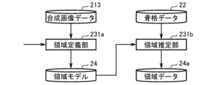
- FIG. 6 is a block diagram showing a processing unit related to regions.
- the area definition section 231 a of the model generation section 211 allows the user to define an area on the image data 210 as polygonal (quadrilateral) coordinate data via the input/output device 14 , and stores the defined data as the area model 24 of the model data 212 .
- the background detection section 233 of the analysis unit 23 uses the stored background model 291 and the image data 210 to analyze the image content within the background area of the image data 213, and outputs the analysis result (equipment work status) as background data 291a of the estimation result data 27.
- Image data 213 is generated by extracting and synthesizing the area of the area model 24, the area of the background model 291, and the area where people are mainly photographed based on the image data 210.
- FIG. 9 is a block diagram showing a processing section related to procedures and an output section 28 that outputs the processing results.
- the model data 212 including the area model 24, the posture model 25, the background model 291, and the procedure model 297, and the estimation result data 27 including the area data 24a, the posture data 25a, the background data 291a, and the procedure data 297a are each stored in the memory unit 200 of the work management device 2.
- the procedure detection unit 237 combines the estimation result data 27 of the intermediate analysis results of each of the "area data 24a, posture data 25a, and background data 291a" to determine the final procedure data 297a (task state) of the worker. Even if one of the three types of intermediate analysis results is erroneously estimated, the remaining two types are correctly estimated, thereby improving the final accuracy.
- the process of determining procedure data 297a by the procedure detection unit 237 requires a procedure model 297, which is model data 212 for obtaining procedure data 297a from a combination of intermediate model data 212 of each of the "area model 24, posture model 25, and background model 291.” Therefore, the procedure learning unit 237a displays a combination of intermediate analysis results for each of "area, posture, and background” and accepts a correct label (procedure label) from a user who sees the display. The procedure learning unit 237a learns the combination of intermediate analysis results and the procedure label, and stores the learning result as a procedure model 297 of the model data 212. In this way, by combining learning and inference using machine learning techniques, analysis can be performed efficiently in a shorter time.
- An output calculation unit 281 of the output unit 28 receives the estimation result data 27 and executes the calculation process exemplified below so as to produce data required by the output destination.
- the HTML output unit 282 converts the estimation result data 27 into HTML format (browser display) and outputs it to the monitor 31.
- the CSV output unit 283 converts the estimation result data 27 into a file in CSV format and outputs it to the storage device 32.
- the socket communication unit 284 outputs the estimation result data 27 to the application device 33 by socket communication.
- step S314 posture learning unit 232a holds the combination of skeletal data 22 of step S312 and the posture label of step S313 as learning data for the selected frame.
- step S315 if there is an unprocessed frame, posture learning unit 232a returns the process to step S301.
- step S316 similarly to step S306, the posture learning unit 232a executes machine learning using the learning data in step S314 as an input.
- step S317 posture learning unit 232a stores the learning result of step S316 as posture model 25 (described later in FIG. 16).
- FIG. 15 is a diagram showing a GUI screen in the learning process of the orientation detection unit 232 in FIG.
- the user performs correct labeling using the GUI screen 810 of the input/output device 14.
- the user selects an image from the image selection field 812 using the frame advance button or slider while viewing learning images from the image display field 811.
- the user indicates whether the selected image is "take out from the right,””assemble,””place on the left,” or “other” by pressing a button in the correct label input field 813.
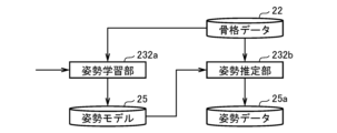
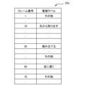
- FIG. 16 is a diagram showing a posture model 25 generated as a result of the learning process of posture detection unit 232 in FIG. 15, and the correct label, and the skeletal data 22 of the person detected in the frame, as a posture model 25 that is a result of machine learning.
- This posture model 25 is used to learn the working posture of screwdriver, for example, and to estimate whether or not a screwdriver is being performed.
- FIG. 16 shows a posture model 25 for determining "take out from the right", “assemble”, “place on the left", or “other” from the posture of the person in the image displayed in the image display field 811 in FIG. 15.
- FIG. 17 is a diagram showing a procedure model 297 that is a result of learning by procedure learning unit 237a.
- the procedure model 297 is a model for outputting a procedure of a worker estimated from an input model that is a combination of the region model 24, the posture model 25, and the background model 291.
- an assembly task is composed of the following procedures.
- the part-picking procedure is a procedure for obtaining the part to be assembled that is located to the right of the worker.
- the assembly procedure involves tightening the screws using a screwdriver.
- the part storage procedure involves placing the completed assembled part to the left of the worker. For example, by using the area model 24 alone, it is possible to understand "how" a person's hand moved, but it is unclear "what" the person's hand grabbed.
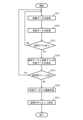
- FIG. 18 is a flowchart showing the main processing of the analysis unit 23.
- the analysis unit 23 acquires the model data 212 .
- the analysis unit 23 acquires the image data 213 for analysis.
- the analysis unit 23 causes the skeleton extraction unit 21 to extract skeleton data 22 from the image data 213 in step S412.
- the analysis unit 23 causes the area detection unit 231 to execute an estimation process of the area data 24a (step S422, see FIG. 19 for details).
- posture model 25 exists (Yes at step S423), analysis unit 23 causes posture detection unit 232 to execute processing for estimating posture data 25a (step S424; see FIG. 22 for details).
- step S425 if an unprocessed person exists in the image data 210 of step S412, the analysis unit 23 returns the process to step S21.
- the analysis unit 23 causes the background detection unit 233 to execute an estimation process of the background data 291a (step S427, see FIG. 25 for details).
- step S431 if there is an unprocessed frame, the analysis unit 23 returns the process to step S412.
- step S432 the analysis unit 23 causes the procedure detection unit 237 to estimate a work procedure from the analysis results of steps S422, S424, and S427.
- FIG. 19 is a flowchart showing a subroutine process of the area detection unit 231.
- the area detection unit 231 obtains, for each frame, the skeletal data 22 of the person detected in that frame.
- the area detection unit 231 acquires one record (one area) from the area model 24.
- the area detection unit 231 retains the area label of the record acquired in step S222 (step S224).
- FIG. 21 is a diagram showing the result of the processing in FIG. 19 when both hands are recognized in the "finished product storage area.”
- the area detection unit 231 estimates area data 24a including the area label "parts are stored on the left side" for the finished product storage area 902 on the image data 213 in Figure 11 by satisfying the requirements of the second record (finished product storage area) of the area model 24 in Figure 12 (i.e., both hands can be placed on the left side).
- FIG. 23 is a diagram showing image data 210 used in the processing of FIG. 22.
- lines indicating the skeletal data 22 recognized by the skeleton extraction unit 21 are also superimposed on the image of the person. Note that in practice, the detection process is performed using image data 213 that combines the person area and object area of the image data 210.
- the work management device 2 is, for example, a computer system such as an on-premise server or a cloud server.
- the work management device 2 is configured as a computer having a CPU (Central Processing Unit), memory, a storage means (storage unit) such as a hard disk, and a network interface.
- the CPU executes a program (also called an application or its abbreviation, an app) loaded into the memory, thereby operating a control unit (control means) made up of each processing unit.
- the work management device 2 may also be equipped with a GPU (Graphics Processing Unit), and the GPU may be used to analyze and display the model.
- GPU Graphics Processing Unit
- the estimation accuracy will improve. For example, when only an image is used, the state of tools or equipment used in assembly or inspection may not be recognized from the image due to being in the shadow of a person, etc. In the above example, the accuracy is poor because the judgment is based on three-dimensional element information, which is missing the element information of the object, out of the four-dimensional element information from the image (area, posture, background, object). In this regard, in this embodiment, the element of sound is added to this, so if the sound of snapping when using pliers can be confirmed, the evaluation will increase the probability of classification into cluster X.
- the location where the sound or voice is generated is roughly determined, by pointing a directional microphone, it is possible to recognize the sound or voice more accurately without picking up ambient noise. It is also possible to recognize the sound when a tool is taken out, the sound when a tool is put down, and when a tool is taken out, a buzzer can be sounded by the change in weight, and it is also possible to recognize the number of times an electric screwdriver has been turned from the sound, for example.
- a score indicating the likelihood of false positives of images, skeletons, and sounds (or voice) can be obtained as a result of machine learning.
- the score is set to a predefined threshold, and detection results with clearly low scores can be excluded from the results.
- Markers 911 and 912 are markers captured in image data 210, and are used by image processing unit 202 to determine person area 910 for recognizing a person. Image processing unit 202 recognizes markers 911 and 912 and sets person area 910 before executing work management processing.
- the image processing unit 202 may determine the person area for recognizing a person and the area for recognizing an object based on pattern matching before executing the work management process. Also, the image processing unit 202 may display a screen on which the person area for recognizing a person and the area for recognizing an object can be adjusted, allowing the adjustment to be performed manually.
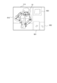
- FIG. 32 is a diagram showing an example of skeleton data 42 extracted from an image input to the work management device 2, and a part-taking area 901, a tool area 903, and a finished product storage area 902 that are set in advance.
- the skeleton data 42 is a result of the skeleton extraction unit 21 extracting human skeleton information from the image data 210 and superimposing the result on the image data 210, with each feature point being shown connected by a line.
- the skeleton extraction unit 21 can use a known technique for acquiring skeleton information, such as OpenPose (URL: https://github.com/CMU-Perceptual-Computing-Lab/openpose).
- the part-taking area 901 is an area where parts are placed, superimposed on the image data 210.
- the analysis unit 23 estimates that the worker's working state is "part-taking.”
- the tool area 903 is an area where a tool is placed, superimposed on the image data 210. When a tool is present in the tool area 903, the analysis unit 23 estimates that the worker does not yet have the tool.
- the finished product storage area 902 is an area where the finished product is stored, superimposed on this image data 210.
- the analysis unit 23 estimates that the worker's work status is "completed.”
- FIG. 33 is a diagram showing an example of image data 213 after synthesis.
- the image processing unit 202 removes unnecessary parts from the image data 210 in Fig. 32.
- the image processing unit 202 synthesizes the parts taking area 901, the finished product storage area 902, the tool area 903, and the person area 910 from the image data 210, and processes the image data into new image data 213.
- the image processing unit 202 is not limited to this, and may perform deformation, color adjustment, filter processing, etc. on each area as necessary during synthesis. By cutting out a plurality of areas to be recognized from the large-sized image data 210 and forming them into a single image, the image data 213 becomes smaller in size than the original image data 210 .
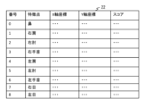
- FIG. 34 is a diagram showing an example of the skeleton data 22.
- the skeleton data 22 includes a number column, a feature point column, an X-axis coordinate column, a Y-axis coordinate column, and a score column.
- Feature points such as the joints of a person are stored in each row.
- the number column a unique number is assigned to each feature point, for example, 0 for the nose, 1 for the right shoulder, 2 for the right elbow, and so on.
- the feature point column stores the name of the feature point.
- the X-axis coordinate column stores the X-axis coordinate value of the feature point in the image data 210.
- the Y-axis coordinate column stores the Y-axis coordinate value of the feature point in the image data 210.
- the score column stores a numerical value representing the likelihood of the feature point.
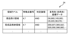
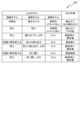
- FIG. 35 is a diagram showing an example of the area model 24.
- the area model 24 includes an area label column, a feature point number column, a judgment logic column, and a polygon coordinate column.
- the area label column is a column that stores the name of this area.
- the feature point number column is a column that stores one or more feature point numbers of the skeleton data 22.
- the "logical product" of the judgment logic indicates a judgment based on the logical product of the feature point numbers (for example, both hands), and the "logical sum” indicates a judgment based on the logical sum of the feature point numbers (for example, one hand).
- the "logical sum” indicates a judgment based on the logical sum of the feature point numbers (for example, one hand).
- the second row of the area model 24, as the finished product storage area 902 in Figure 32, is recognized as the worker storing the assembled finished product when any (logical OR) of the feature point numbers (#3 indicates the right wrist, #6 indicates the left wrist) of the worker's skeletal data 22 exists within the polygon (rectangle) coordinate data (four vertex coordinates).
- the third row of the area model 24 indicates that when both (logical product) of the feature point numbers (#3 indicates the right wrist, #6 indicates the left wrist) of the worker's skeletal data 22 exist within the polygon (rectangle) coordinate data (four vertex coordinates) as the tool area 903 in Figure 32, it is recognized that the worker has taken the screwdriver or put it back.
- posture A in work process A was measured between time t0 and t2 and between time t3 and t4, but posture A was not measured between time t2 and t3.
- sound information DM sound A in work process A was measured over almost the entire period.
- the inference result at this time is as shown on the left side of Figure 39.
- T0 during which posture is not detected within the period T during which work process A is performed
- T1 during which both posture and sound are detected for at least a certain period of time within this period T, so it is determined that the possibility of process A is high.
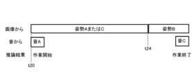
- FIG. 37 is a time chart showing the work content of the worker. 37 shows a case including a section in which it is not possible to recognize whether posture A or posture C is present from the image.
- the actual work process was work process A from time t0 to t4, and then moved to process B.
- posture A or posture C in work process A was measured between time t1 and t4.
- sound information sound A in work process A was measured throughout almost the entire period.
- FIG. 39 is a time chart showing the work content of the worker. Although there is a section in which posture A and posture C coexist within the period T during which work process A is performed, there is a time period T1 within this period T during which both posture A and sound are detected for at least a certain period of time, so it has been determined that the possibility of process A is high.
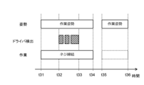
- the bar graph to the right of "Driver Detection” indicates that from time t2 to t3, the object detection unit 234 detected the driver near the right or left wrist of the worker.
- the bar graph to the right of "Work” shows the work content of the worker estimated by the analysis unit 23. From time t1 to t4, the work is estimated to be screw tightening. This is because a screwdriver was detected near the worker's wrist during part of the time period from t1 to t4. In contrast, from time t5 to t6, a screwdriver was not detected, so the work is not estimated to be screw tightening.
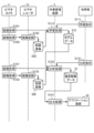
- the image processing unit 202 acquires each frame constituting the moving image as image data (step S11). Then, the image processing unit 202 processes a plurality of regions to be recognized into new image data 213 (step S12). Then, the skeleton extraction unit 21 extracts the skeleton data 22 of the worker from the processed image data 213 (step S13).
- the analysis unit 23 performs detection processing in parallel. Specifically, the area detection unit 231 detects areas in the frame based on the area model 24 (step S14). The posture detection unit 232 detects a posture from the skeleton data 22 based on the posture model 25 (step S15). Here, the posture detection unit 232 calculates a score (likelihood) of the detected posture. If the score is equal to or greater than a threshold, the posture is considered to have been detected, and a character string (label) indicating the detection is output.
- a score likelihood
- the object detection unit 234 detects an object from the frame based on the object model 26 and the skeleton data 22 (step S17). Here, the object detection unit 234 calculates a score (likelihood) of the detected object. If the score is equal to or greater than a threshold, the object is deemed to have been detected, and a character string (label) indicating the detection is output. For object detection, since feature points are defined in the object model 26, the object detection range is set according to the coordinates of the skeleton data 22 extracted in advance, and detection is performed.
- the sound detection unit 235 detects the corresponding work content based on the sound model 293 and the sound data 296 (step S18).
- the movement detection unit 236 detects movement based on the movement analysis model 294 and the movement analysis data 295 (step S19).
- step S20 the analysis unit 23 performs a filter process based on the number of past detections to suppress flickering of the detected area, orientation, background, and object.
- the analysis unit 23 then calculates the detection times of the area, orientation, background, and object (step S21).
- the analysis unit 23 estimates the work based on these calculated detection times. Specifically, the analysis unit 23 performs a process of combining these detection results (step S22).
- the analysis unit 23 performs calculations by combining the calculated detection results based on the data defined as the combination model 292, and estimates the work content being performed by the worker.
- Combination model 292 stores, for example, a combination of the logical product of the detection of a hand entering the part-removing area, the detection of a posture for removing a part, and the start of a task. Furthermore, combination model 292 stores a combination of the logical product of the detection of a working posture, the detection of a screwdriver near the wrist, and a screw tightening task.
- the analysis unit 23 performs a logical AND between the detection of whether the hand has entered the part-picking area where the parts are placed using area detection, and the detection of whether the hand is in a position to pick up the parts using posture detection, and if the result is true, it determines that the starting work is being performed.
- FIG. 42 is a flowchart showing the process of associating a working posture with a driver.
- the analysis unit 23 determines whether the object detection unit 234 has detected the driver (step S40). If the object detection unit 234 has not detected the driver (No), the analysis unit 23 ends the process of Fig. 42, and if the object detection unit 234 has detected the driver (Yes), the analysis unit 23 proceeds to step S41.
- the analysis unit 23 determines whether or not the posture detection unit 232 has detected a working posture (step S41). If the analysis unit 23 has not detected a working posture (No), it ends the process of FIG. 42, and if the analysis unit 23 has detected a working posture (Yes), it proceeds to step S42.
- step S42 the analysis unit 23 determines that the work time is equal to the detection time of the working posture, and thus the screw tightening work time, and ends the process in FIG. 42.
- the analysis unit 23 can also perform logical sum or logical product operations on the work time.
- the object detected by the object detection unit 234 is not limited to a screwdriver, but may be a brush, an air gun, a soldering iron, a wrench, etc.
- the work content estimated by the analysis unit 23 is not limited to screw tightening, but may be painting work when a brush or air gun is detected, soldering work when a soldering iron is detected, bolt tightening work when a wrench is detected, etc.
- the analysis unit 23 determines whether the work state estimated from the latest frame is a starting work state (step S23). If it is a starting work state (Yes), the analysis unit 23 starts measuring the work time (step S24) and proceeds to step S27. If it is not a starting work state (No), the analysis unit 23 proceeds to step S25.
- step S25 the analysis unit 23 determines whether the work state estimated from the latest frame is a completed work state. If it is a completed work state (Yes), the analysis unit 23 ends the measurement of the work time (step S26) and proceeds to step S27. If it is not a completed work state (No), the analysis unit 23 proceeds to step S27.
- step S27 the analysis unit 23 checks the work sequence.
- the analysis unit 23 may record, as a work attribute, any work that deviates from the predetermined work sequence. This allows the analysis unit 23 to distinguish and display work that follows the predetermined work sequence and work that deviates from the predetermined work sequence.
- the analysis unit 23 then outputs the intermediate result (step S28).
- the analysis unit 23 determines whether or not there are any unprocessed frames (step S29). If there are any unprocessed frames (Yes), the analysis unit 23 returns to the process of step S11, and if all frames have been processed (No), the analysis unit 23 proceeds to step S30.
- step S30 the analysis unit 23 outputs the estimation result data 27, and then ends the processing of FIGS. 41A and 41B.
- the analysis unit 23 estimates the work being performed by the worker based on the detection results of the driver and the detection results of the worker's posture. This makes it possible to suitably extract the content of each work even if the worker performs multiple different works in similar postures.
- FIG. 43 is a diagram showing the real-time screen 5 displayed by the work management device 2. As shown in FIG. 43 is a screen showing execution, interruption, and stop of analysis, and the results of the analysis.
- the output unit 28 displays this real-time screen 5 on the monitor 31.
- the real-time screen 5 includes an execution button 51, a pause button 52, a stop button 53, a video display area 56, a status display field 54, a status cumulative time graph 55, and a status time chart 57.
- the video display area 56 is an area where the analysis results are superimposed on the input image data.
- the execute button 51 is for executing the analysis.
- the pause button 52 is for pausing the execution of the analysis.
- the stop button 53 is for stopping the execution of the analysis.
- the status display column 54 shows the current analysis status, and displays the start and end of work, as well as the status of major tasks.
- the status cumulative time graph 55 is a bar graph that shows the cumulative time of work in the video being analyzed.
- the status time chart 57 shows the most recent analysis results in a time chart.
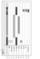
- FIG. 44 is a diagram showing the history data screen 6 displayed by the work management device 2. As shown in FIG.
- the history data screen 6 includes time charts showing the analysis results.
- the state time chart 60 is a time chart showing a state determined comprehensively based on the score (likelihood) of the analysis result at each time.
Landscapes
- Engineering & Computer Science (AREA)
- Computer Vision & Pattern Recognition (AREA)
- Physics & Mathematics (AREA)
- General Physics & Mathematics (AREA)
- Theoretical Computer Science (AREA)
- Image Analysis (AREA)
Priority Applications (2)
| Application Number | Priority Date | Filing Date | Title |
|---|---|---|---|
| JP2024509021A JP7500895B1 (ja) | 2023-09-21 | 2023-09-21 | 作業管理装置、作業管理システム、および、作業管理方法 |
| PCT/JP2023/034205 WO2025062550A1 (ja) | 2023-09-21 | 2023-09-21 | 作業管理装置、作業管理システム、および、作業管理方法 |
Applications Claiming Priority (1)
| Application Number | Priority Date | Filing Date | Title |
|---|---|---|---|
| PCT/JP2023/034205 WO2025062550A1 (ja) | 2023-09-21 | 2023-09-21 | 作業管理装置、作業管理システム、および、作業管理方法 |
Publications (1)
| Publication Number | Publication Date |
|---|---|
| WO2025062550A1 true WO2025062550A1 (ja) | 2025-03-27 |
Family
ID=91483373
Family Applications (1)
| Application Number | Title | Priority Date | Filing Date |
|---|---|---|---|
| PCT/JP2023/034205 Pending WO2025062550A1 (ja) | 2023-09-21 | 2023-09-21 | 作業管理装置、作業管理システム、および、作業管理方法 |
Country Status (2)
| Country | Link |
|---|---|
| JP (1) | JP7500895B1 (https=) |
| WO (1) | WO2025062550A1 (https=) |
Families Citing this family (1)
| Publication number | Priority date | Publication date | Assignee | Title |
|---|---|---|---|---|
| JP7832380B1 (ja) * | 2025-01-28 | 2026-03-17 | エクシオグループ株式会社 | 作業時間計測装置 |
Citations (3)
| Publication number | Priority date | Publication date | Assignee | Title |
|---|---|---|---|---|
| JP2020201772A (ja) * | 2019-06-11 | 2020-12-17 | 株式会社 日立産業制御ソリューションズ | 姿勢分析プログラム、および、姿勢分析装置 |
| JP2021072475A (ja) * | 2019-10-29 | 2021-05-06 | パナソニックIpマネジメント株式会社 | 監視システムおよび監視システム設定プログラム |
| JP2021163188A (ja) * | 2020-03-31 | 2021-10-11 | コベルコ建機株式会社 | 作業機械の周囲検知装置 |
Family Cites Families (1)
| Publication number | Priority date | Publication date | Assignee | Title |
|---|---|---|---|---|
| JP7739020B2 (ja) * | 2021-03-30 | 2025-09-16 | キヤノン株式会社 | 画像処理装置、画像処理方法、移動装置、及びコンピュータプログラム |
-
2023
- 2023-09-21 JP JP2024509021A patent/JP7500895B1/ja active Active
- 2023-09-21 WO PCT/JP2023/034205 patent/WO2025062550A1/ja active Pending
Patent Citations (3)
| Publication number | Priority date | Publication date | Assignee | Title |
|---|---|---|---|---|
| JP2020201772A (ja) * | 2019-06-11 | 2020-12-17 | 株式会社 日立産業制御ソリューションズ | 姿勢分析プログラム、および、姿勢分析装置 |
| JP2021072475A (ja) * | 2019-10-29 | 2021-05-06 | パナソニックIpマネジメント株式会社 | 監視システムおよび監視システム設定プログラム |
| JP2021163188A (ja) * | 2020-03-31 | 2021-10-11 | コベルコ建機株式会社 | 作業機械の周囲検知装置 |
Also Published As
| Publication number | Publication date |
|---|---|
| JP7500895B1 (ja) | 2024-06-17 |
| JPWO2025062550A1 (https=) | 2025-03-27 |
Similar Documents
| Publication | Publication Date | Title |
|---|---|---|
| JP6825041B2 (ja) | 姿勢分析プログラム、および、姿勢分析装置 | |
| CN106340217B (zh) | 基于增强现实技术的制造装备智能系统及其实现方法 | |
| JP6928880B2 (ja) | 動作分析装置、動作分析方法、動作分析プログラム及び動作分析システム | |
| CN108596148B (zh) | 一种基于计算机视觉的建筑工人劳动状态分析系统及方法 | |
| CN111507317B (zh) | 一种基于视觉的旋转设备作业手套佩戴检测方法及系统 | |
| CN112949457A (zh) | 基于增强现实技术的维修方法、装置及系统 | |
| JPWO2018154709A1 (ja) | 動作学習装置、技能判別装置および技能判別システム | |
| CN113469063A (zh) | 一种基于计算机视觉的建筑工人劳损预警分析方法及系统 | |
| JP7500895B1 (ja) | 作業管理装置、作業管理システム、および、作業管理方法 | |
| JP6773825B2 (ja) | 学習装置、学習方法、学習プログラム、及び対象物認識装置 | |
| Collett et al. | Augmented reality visualisation for player | |
| JP7737964B2 (ja) | 作業管理装置、作業管理システム、および、作業管理プログラム | |
| JP5097629B2 (ja) | 地物形状変化検出プログラム、及び、地物形状変化検出システム | |
| JP2022055077A (ja) | 安全管理プログラム、および、安全管理装置 | |
| JP7776397B2 (ja) | 仮想三次元空間共有システム、仮想三次元空間共有方法、及び仮想三次元空間共有サーバ | |
| JP2021056808A (ja) | 情報処理装置、情報処理方法、及びプログラム | |
| CN112102502B (zh) | 用于飞机驾驶舱功能试验的增强现实辅助方法 | |
| JP2022055057A (ja) | 作業分析プログラム、および、作業分析装置 | |
| JP2024063801A (ja) | 行動識別装置、行動識別装置の制御方法、プログラム、及び記憶媒体 | |
| CN111028339B (zh) | 一种行为动作建模方法、装置、电子设备和存储介质 | |
| CN115273215A (zh) | 作业识别系统以及作业识别方法 | |
| JP2007048232A (ja) | 情報処理装置、および情報処理方法、並びにコンピュータ・プログラム | |
| JP7821356B1 (ja) | 作業管理装置、および、作業管理方法 | |
| JP7766886B1 (ja) | 情報処理システム、情報処理方法、学習モデルの生成方法、及びコンピュータプログラム | |
| US20240281730A1 (en) | Control device and information presentation method |
Legal Events
| Date | Code | Title | Description |
|---|---|---|---|
| ENP | Entry into the national phase |
Ref document number: 2024509021 Country of ref document: JP Kind code of ref document: A |
|
| WWE | Wipo information: entry into national phase |
Ref document number: 2024509021 Country of ref document: JP |
|
| 121 | Ep: the epo has been informed by wipo that ep was designated in this application |
Ref document number: 23953037 Country of ref document: EP Kind code of ref document: A1 |