WO2025052844A1 - 端末、管理サーバ、通信システム、方法及びプログラム - Google Patents
端末、管理サーバ、通信システム、方法及びプログラム Download PDFInfo
- Publication number
- WO2025052844A1 WO2025052844A1 PCT/JP2024/028166 JP2024028166W WO2025052844A1 WO 2025052844 A1 WO2025052844 A1 WO 2025052844A1 JP 2024028166 W JP2024028166 W JP 2024028166W WO 2025052844 A1 WO2025052844 A1 WO 2025052844A1
- Authority
- WO
- WIPO (PCT)
- Prior art keywords
- terminal
- data
- haptic data
- communication
- network
- Prior art date
- Legal status (The legal status is an assumption and is not a legal conclusion. Google has not performed a legal analysis and makes no representation as to the accuracy of the status listed.)
- Ceased
Links
Images




Classifications
-
- G—PHYSICS
- G06—COMPUTING OR CALCULATING; COUNTING
- G06F—ELECTRIC DIGITAL DATA PROCESSING
- G06F3/00—Input arrangements for transferring data to be processed into a form capable of being handled by the computer; Output arrangements for transferring data from processing unit to output unit, e.g. interface arrangements
- G06F3/01—Input arrangements or combined input and output arrangements for interaction between user and computer
-
- H—ELECTRICITY
- H04—ELECTRIC COMMUNICATION TECHNIQUE
- H04L—TRANSMISSION OF DIGITAL INFORMATION, e.g. TELEGRAPHIC COMMUNICATION
- H04L65/00—Network arrangements, protocols or services for supporting real-time applications in data packet communication
- H04L65/80—Responding to QoS
-
- H—ELECTRICITY
- H04—ELECTRIC COMMUNICATION TECHNIQUE
- H04N—PICTORIAL COMMUNICATION, e.g. TELEVISION
- H04N21/00—Selective content distribution, e.g. interactive television or video on demand [VOD]
- H04N21/40—Client devices specifically adapted for the reception of or interaction with content, e.g. set-top-box [STB]; Operations thereof
- H04N21/43—Processing of content or additional data, e.g. demultiplexing additional data from a digital video stream; Elementary client operations, e.g. monitoring of home network or synchronising decoder's clock; Client middleware
- H04N21/437—Interfacing the upstream path of the transmission network, e.g. for transmitting client requests to a VOD server
Definitions
- This disclosure relates to a terminal, a management server, a communication system, a method, and a program.
- Patent Document 1 discloses a connection management system that includes a concierge assistant service for handling a wide range of topics and user intents via a common interface.
- the connection management system interprets the intent of natural language communication received from a user device and automatically determines the social network member endpoint that will receive the natural language communication based on the intent.
- haptic data which is data related to at least one of the tactile and/or kinesthetic senses
- the receiving device that receives the haptic data transmits the data to the user via an interface. This allows the user to experience virtual reality related to touch, etc.
- a user when a user performs remote operation on one device, data related to the remote operation instructions is transmitted from one device to the other device.
- the other device performs an operation based on those instructions.
- the other device transmits haptic data generated by the operation to the one device. Because the user can experience the haptic data via the interface, they can get the feeling that they are actually performing some kind of action on the spot. This allows the user to perform the operation they desire.
- Patent Document 1 does not address this issue, as it is not targeted at haptic technology.
- the present disclosure has as an example an objective to provide a terminal, management server, communication system, method, and program capable of improving the communication performance of haptic data. It should be noted that this objective is merely one of multiple objectives that the multiple embodiments disclosed herein attempt to achieve. Other objectives or problems and novel features will become apparent from the description in this specification or the accompanying drawings.
- a terminal includes a receiving unit that receives haptic data from other terminals connected via a network, a generating unit that generates instruction information for a management server on the network based on an indicator indicating the communication state of the haptic data to execute control regarding the communication of the haptic data with the other terminals, and a transmitting unit that transmits the instruction information to the management server.
- a management server includes a receiving unit that is connected to a first terminal via a network and receives instruction information from a second terminal that receives haptic data from the first terminal, for executing control over communication of the haptic data with the first terminal, and a control executing unit that executes control over communication of the haptic data based on the instruction information.
- a communication system includes a terminal and a management server.
- the terminal includes a receiving unit that receives haptic data from other terminals connected via a network, a generating unit that generates instruction information for the management server on the network based on an indicator indicating a communication state of the haptic data to execute control regarding the communication of the haptic data with the other terminals, and a transmitting unit that transmits the instruction information to the management server.
- the management server includes a receiving unit that receives the instruction information from the terminal, and a control executing unit that executes control regarding the communication of the haptic data based on the instruction information.
- a method is performed by a computer to receive haptic data from another terminal connected via a network, generate instruction information for a management server on the network based on an indicator of a communication state of the haptic data, for controlling communication of the haptic data with the other terminal, and transmit the instruction information to the management server.
- a method is implemented by a computer that receives, from a second terminal that is connected to a first terminal via a network and receives haptic data from the first terminal, instruction information for executing control related to communication of the haptic data with the first terminal, and executes control related to the communication of the haptic data based on the instruction information.
- a program causes a computer to receive haptic data from another terminal connected via a network, generate instruction information for a management server on the network based on an indicator indicating a communication state of the haptic data, for controlling communication of the haptic data with the other terminal, and transmit the instruction information to the management server.
- a program causes a computer to receive, from a second terminal that is connected to a first terminal via a network and receives haptic data from the first terminal, instruction information for executing control over communication of the haptic data with the first terminal, and execute control over the communication of the haptic data based on the instruction information.
- a terminal a management server, a communication system, a method, and a program that can improve the communication performance of haptic data.
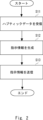
- FIG. 2 is a block diagram illustrating an example of a terminal according to the present disclosure.
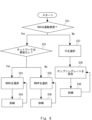
- 10 is a flowchart illustrating an example of a representative process of a terminal according to the present disclosure.
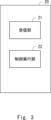
- FIG. 2 is a block diagram illustrating an example of a management server according to the present disclosure.
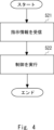
- 13 is a flowchart illustrating an example of a representative process of a management server according to the present disclosure.
- FIG. 1 is a block diagram illustrating an example of a remote control system according to the present disclosure.
- FIG. 1 illustrates an example of a haptic encoder selection scheme according to the present disclosure.
- 1A-1C illustrate different examples of haptic encoder selection schemes according to the present disclosure.
- FIG. 13 is a diagram showing a specific example of the SEEHC header.
- FIG. 1 is a table illustrating SEEHC header coding.
- FIG. 13 is a diagram showing an example of a payload configuration of a feedback bitstream corresponding to a forward bitstream.
- FIG. 11 is a diagram showing another specific example of the SEEHC header.
- FIG. 13 is a diagram showing another example of the payload structure of a feedback bitstream corresponding to a forward bitstream.
- 1 is a table showing actions associated with the SEEHC scheme when there is no delay.
- 1 is a table showing actions associated with the SEEHC scheme when there is a delay.
- FIG. 11 is a sequence diagram showing a procedure for detecting an SE server that is initiated and executed by a leader terminal.
- FIG. 11 is a sequence diagram showing a procedure for detecting an SE server that is initiated and executed by a follower terminal.
- FIG. 13 is an image showing training of SE server 140 with expert profiles.
- FIG. 1 is a block diagram showing an effect of the present disclosure.
- FIG. 2 is a block diagram illustrating an example of a hardware configuration of an information processing device.
- FIG. 1 is a block diagram showing an example of a terminal.
- the terminal 10 is any type of computer that includes a receiving unit 11, a generating unit 12, and a transmitting unit 13. Each unit (means) of the terminal 10 is controlled by a control unit (controller) not shown. Each unit will be described below.
- the receiving unit 11 receives haptic data from other terminals connected via the network.
- haptic data is data related to at least either the sense of touch or the sense of movement.
- the haptic data transmitted by the other terminals is generated, for example, due to an action by a human or a machine (e.g., a robot) being executed on the other terminal side.
- the haptic data acquired by the other terminals is transmitted to the terminal 10.
- the network connecting the terminal 10 and other terminals may be any type of network.
- a management server that manages communication related to haptic data between the terminal 10 and other terminals is provided on the network.
- the generating unit 12 generates instruction information for a management server on the network to execute control regarding the communication of haptic data with other terminals, based on an indicator indicating the communication status of the haptic data received by the receiving unit 11.
- the index indicating the communication state of the haptic data is any qualitative or quantitative index relating to the communication state.
- the index include QoE (Quality of Experience), QoS (Quality of Service), packet loss, transmission delay, etc., but the indexes that can be used are not limited to these.
- This index may be obtained by the terminal 10 analyzing the haptic data received by the receiving unit 11. Alternatively, when a user of the terminal 10 experiences haptic data, the user may input the QoE relating to that data into the terminal 10, and the terminal 10 may obtain the QoE. A specific example of this will be described later in embodiment 2.
- examples of the instruction information generated by the generation unit 12 include the following.
- the parameters related to the network predicted by the management server in (A) may be, but are not limited to, at least one of packet loss, packet error, CRC (Cyclic Redundancy Check) error, error rate, bit rate, jitter, transmission delay, transmission speed, connection loss, bandwidth, capacity, load balancing, HAV data configuration, data stream, data flow, active session, retransmission, and codec selection.
- the management server may predict what kind of haptic data will be generated as a result of a human or machine action performed on the other terminal side. The management server can insert data generated as a result of the prediction into the haptic data acquired from the other terminal and transmitted to the terminal 10, and transmit the data to the terminal 10.
- the objects predicted in (B) are not limited to this.
- the transmission unit 13 transmits the instruction information to the management server.
- the transmission unit 13 is configured as an interface used for wireless or wired communication with other terminals.
- the receiving unit 11 receives haptic data from another terminal connected via the network (step S11).
- the generating unit 12 generates instruction information for changing the control regarding the communication of haptic data with another terminal based on an indicator indicating the communication state of the haptic data (step S12).
- the transmitting unit 13 transmits the instruction information to the management server (step S13).
- the terminal 10 can generate instruction information based on an index indicating a communication state of the haptic data and transmit the instruction information to the management server. Therefore, the terminal 10 can improve the communication performance of the haptic data through the control of the management server.
- the terminal 10 can cause the management server to predict network parameters and control communications based on the predicted parameters. Therefore, through the control of the management server, the terminal 10 can improve the communication performance of haptic data so that the network parameters are favorable.
- terminal 10 can have the management server predict haptic data to be generated on the other terminal side, and based on the predicted haptic data, change the content of the haptic data to be transmitted to the terminal and transmit it to the terminal.
- terminal 10 through the control of the management server, can make the haptic data it receives closer to the content generated on the other terminal side and that should originally be transmitted to terminal 10. Therefore, terminal 10 can improve the communication performance of haptic data so that terminal 10 can receive haptic data that is close to the original data.
- FIG. 3 is a block diagram showing an example of the management server.
- the management server 20 is any type of computer equipped with a receiving unit 21 and a control execution unit 22. Each unit (each means) of the management server 20 is controlled by a control unit (controller) not shown. Each unit will be described below.
- the receiving unit 21 is connected to a first terminal via a network, and receives instruction information from a second terminal that receives haptic data from the first terminal, for changing control over communication of haptic data with the first terminal.
- haptic data, instruction information, and network are the same as those in (1A), and therefore will not be repeated.
- the control execution unit 22 executes control regarding the communication of haptic data based on the instruction information received by the receiving unit 21.
- the control execution unit 22 predicts parameters related to the network between the first terminal and the second terminal, and controls the communication between the first terminal and the second terminal based on the predicted parameters.
- the control execution unit 22 predicts haptic data to be generated on the first terminal side, and based on the predicted haptic data, controls the content of the haptic data to be transmitted to the second terminal to be changed and transmitted to the terminal.
- the control executed by the control execution unit 22 is not limited to this.
- the management server 20 may transmit information indicating the content of the executed control to at least one of the first terminal or the second terminal.
- [Explanation of processing flow] 4 is a flowchart showing an example of a representative process of the management server 20, and an overview of the process of the management server 20 will be described with reference to this flowchart. Note that the details of each process are as described above, and therefore will not be described here.
- the receiver 21 receives instruction information from the second terminal for executing control related to the communication of haptic data with the first terminal (step S21).
- the control execution unit 22 executes control related to the communication of haptic data based on the instruction information (step S22).
- the management server 20 executes control regarding the communication of haptic data based on instruction information received from the terminal. Therefore, the management server 20 can improve the communication performance of the haptic data in response to an instruction from the terminal.
- Embodiment 2 In the following second embodiment, a specific example of the terminal and management server described in the first embodiment will be disclosed. However, the specific examples of the terminal and management server shown in the first embodiment are not limited to those shown below. Furthermore, the configurations and processes described below are examples and are not limited to these. It goes without saying that all or any part of the configurations described in the second embodiment can be appropriately applied to the first embodiment, and the drawings shown in the second embodiment can be appropriately applied to the first embodiment.
- FIG. 5 is a block diagram showing an example of a remote control system.
- the remote control system 100 is a wide area communication network system including a leader terminal 110, a follower terminal 120, a network 130, and an SE (Support Engine) server 140.
- the leader terminal 110 and the follower terminal 120 correspond to the terminal 10 of the first embodiment
- the SE server 140 corresponds to the management server 20 of the first embodiment.
- the remote operation system 100 is a system that supports medical procedures such as surgery in a remote location.
- the follower terminal 120 is a terminal that is placed at a location where surgery is actually performed on a patient
- the leader terminal 110 is a terminal that is placed at a location where the surgeon (i.e., the user of the leader terminal 110) who performs the surgery performs the operation.
- the leader terminal 110 transmits instructions regarding the operation to the follower terminal 120.
- the follower terminal 120 controls a surgical robot connected to the follower terminal 120 based on the received instructions. In this way, the surgical robot operates according to the surgeon's operation and performs surgery on the patient.
- the surgery targets any part of the body (including, for example, the brain, nerves, etc.).
- the remote operation system 100 can be applied to any medical procedure that invades the patient's body, such as biopsies, injections, and cancer treatments, in addition to surgery.
- the application of the remote operation system 100 is not limited to this.
- the leader terminal 110 may transmit instructions to the follower terminal 120 regarding any action performed by the user, not limited to the user's actions.
- the leader terminal 110 comprises a physical environment 111, a virtual environment 112, a HAV (Haptic Audio Video) data processing unit 113, an encoder/decoder 114, and a QoE acquisition unit 115. Each element of the leader terminal 110 is described below.
- HAV Heaptic Audio Video
- the leader terminal 110 is configured to perform its processing using the physical environment 111 or the virtual environment 112. Note that the leader terminal 110 may be configured to have either the physical environment 111 or the virtual environment 112, rather than both.
- the HAV data processing unit 113 generates HAV data based on data acquired from a sensor connected to the reader terminal 110.
- the generated HAV data includes haptic data, audio data, and video data.
- the sensor is attached to, for example, the surgeon's hand, acquires data on the movement of the surgeon's hand, and transmits it to the HAV data processing unit 113.
- the HAV data processing unit 113 processes the received data to generate HAV data.
- data may be transmitted to the HAV data processing unit 113 from any interface, not limited to sensors.
- the HAV data may include haptic data and audio data or video data, or may be data that does not include audio data or video data and includes haptic data.
- the HAV data processing unit 113 also generates a SEEHC header that includes the selection of a haptic encoder to be used for communicating HAV data and instruction information for the SE server 140, as described below.
- the encoder/decoder 114 is a unit that has both the functions of an encoder and a decoder.
- the encoder/decoder 114 encodes the HAV data generated by the HAV data processing unit 113 for transmission.
- the leader terminal 110 transmits the encoded HAV data to the follower terminal 120 via the network 130.
- the encoder/decoder 114 also decodes the HAV data transmitted from the follower terminal 120 and received via a receiving unit (not shown) of the leader terminal 110.
- the encoder/decoder 114 outputs the decoded HAV data to an actuator attached to a surgical instrument or joystick held by the surgeon, or to a glove or other device worn by the surgeon.
- the actuator operates in response to the HAV data, transmitting sensations such as touch and force to the surgeon's hand.
- haptic data such as touch and force generated in the robot arm on the follower terminal 120 side as a result of the surgeon's surgery is fed back to the surgeon.
- the remote operation system 100 can be said to be a system capable of performing bilateral control.
- the encoder/decoder 114 supports, for example, NDHC (No Delay Haptic Codec), WDHP (With Delay Haptic Codec), and SEEHC formats. Details on how each format is selected will be described later.
- the QoE acquisition unit 115 acquires QoE information on the leader terminal 110 side in communication of HAV data between the leader terminal 110 and the follower terminal 120 (hereinafter also referred to as HAV communication).
- the QoE acquisition unit 115 may acquire QoE information by having a user in the vicinity of the leader terminal 110, such as a surgeon, manually input QoE information to the leader terminal 110.
- the user inputs the evaluation of the HAV data that he or she has experienced as QoE to the QoE acquisition unit 115.
- the QoE experienced by the user may change depending on the presence or absence of communication delay or the degree of delay, or fluctuations in parameters related to communication quality other than delay.
- the QoE acquisition unit 115 may acquire QoE information automatically.
- the QoE acquisition unit 115 can acquire QoE information using any method such as QoE-related measurement, a QoE point system, MOS (Mean Opinion Score), etc. In this way, the QoE acquisition unit 115 can monitor the QoE information. In addition, the QoE acquisition unit 115 can also report the status of HAV communication to the SE server 140 by sending the QoE information to the SE server 140. The processing of the SE server 140 will be described later.
- the follower terminal 120 comprises a physical environment 121, a virtual environment 122, an HAV data processing unit 123, an encoder/decoder 124, and a QoE acquisition unit 125. Each element of the follower terminal 120 will be explained below. Note that explanations of the same elements as those of the leader terminal 110 will be omitted as appropriate.
- the follower terminal 120 is configured to perform its processing using the physical environment 121 or the virtual environment 122. Note that the follower terminal 120 may be configured to have either the physical environment 121 or the virtual environment 122, rather than both.
- the physical environment 121 and the virtual environment 122 are equivalent to the physical environment 111 and the virtual environment 112 of the leader terminal 110, respectively.
- the HAV data processing unit 123 generates HAV data based on data acquired from a sensor connected to the follower terminal 120.
- the sensor is attached to, for example, a robot arm performing surgery, and acquires data such as the feel of touch and the sense of force of the part of the body that the robot arm comes into contact with, and transmits this data to the HAV data processing unit 123.
- the HAV data processing unit 123 processes this received data to generate HAV data.
- the HAV data processing unit 123 also generates a SEEHC header that includes the selection of a haptic encoder to be used for communicating HAV data and instruction information for the SE server 140, as described below.
- the encoder/decoder 124 is a unit that has both the functions of an encoder and a decoder.
- the encoder/decoder 124 encodes the HAV data generated by the HAV data processing unit 123 for transmission.
- the follower terminal 120 transmits the encoded HAV data to the leader terminal 110 via the network 130. The processing that the leader terminal 110 performs on the transmitted HAV data has already been explained.
- the encoder/decoder 124 also decodes the HAV data transmitted from the leader terminal 110 and received via a receiving section (not shown) of the follower terminal 120.
- the encoder/decoder 124 decodes the HAV data transmitted from the leader terminal 110.
- the encoder/decoder 124 outputs the decoded HAV data to an actuator attached to the robot arm that performs the surgery.
- the actuator operates in response to the HAV data, and the robot arm performs the surgery in response to the operation of a surgeon in a remote location.
- the encoder/decoder 124 supports formats such as NDHC, WDHP, and SEEHC.
- the QoE acquisition unit 125 acquires QoE information on the follower terminal 120 side in HAV communication between the leader terminal 110 and the follower terminal 120.
- a person in the vicinity of the follower terminal 120 may manually input the QoE information into the follower terminal 120, so that the QoE acquisition unit 125 acquires the QoE information.
- the QoE acquisition unit 125 may acquire the QoE information automatically.
- the method by which the QoE acquisition unit 125 automatically acquires the QoE information is the same as that of the QoE acquisition unit 115, and therefore will not be described here. In this way, the QoE acquisition unit 125 can monitor the QoE information.
- the QoE acquisition unit 125 can also report the status of the HAV communication to the SE server 140 by transmitting the QoE information to the SE server 140.
- the SE server 140 is a server that controls HAV communication between the leader terminal 110 and the follower terminal 120, and includes a first function unit 141, a second function unit 142, a first model 143, a second model 144, and an interface 145.
- the SE server 140 is provided to reduce the latency of the network used for HAV communication and improve the QoE of the remote control system 100. Although only one SE server 140 is illustrated in FIG. 5, multiple SE servers 140 may be provided in the remote control system 100.
- the first function unit 141 and the second function unit 142 correspond to the control execution unit 22 according to the first embodiment, and the interface 145 corresponds to the receiving unit 21 according to the first embodiment.
- the first functional unit 141 predicts network parameters specific to HAV communication for optimization.
- the network parameters include at least one of the following parameters: packet loss, packet error, CRC error, error rate, bit rate, jitter, transmission speed, transmission delay, connection loss, bandwidth, capacity, load balancing, HAV data configuration, data stream, data flow, active session, retransmission, codec selection, and encoding/decoding.
- the first functional unit 141 can control the HAV communication based on the predicted network parameters.
- the first functional unit 141 may set parameters for remote rendering in HAV communication or set outsourcing of calculations related to HAV data.
- the first functional unit 141 can also predict multiple different parameters and control the HAV communication based on the predicted parameters.
- different parameters may be predicted and controlled in the first functional unit 141 of each SE server 140.
- the second functional unit 142 predicts at least one of the behavior of the user of the leader terminal 110 or the haptic data detected by the sensor of the robot of the follower terminal 120. This behavior prediction is made to improve the QoE of at least one of the leader terminal 110 or the follower terminal 120 in HAV communication.
- the second functional unit 142 can predict the next (future) behavior of the surgeon on the leader terminal 110 side, thereby controlling the response time to be reduced until the behavior of the surgeon is reflected in the robot arm on the follower terminal 120 side.
- the second functional unit 142 can also predict the haptic data that the sensor of the robot will detect next (in the future).
- the second functional unit 142 can control the response time to be reduced until the surgeon can feel the tactile sensation and force from the patient's body generated in response to the surgeon's surgery. This can improve the QoE in communication.
- the second functional unit 142 can realize the prediction process on the order of milliseconds.
- the second model 144 is also a pre-trained AI model such as a neural network.
- the second functional unit 142 inputs the HAV data acquired by the SE server 140 to the second model 144.
- the second model 144 outputs at least one of the predicted results of human behavior based on the HAV data or haptic data detected by the robot's sensor.
- the interface 145 is an interface that connects the SE server 140 to the leader terminal 110 and the follower terminal 120 via the network 130.
- the interface 145 is, for example, an API (application programming interface), a service API, etc.
- the SE server 140 receives HAV data transmitted from at least one of the leader terminal 110 and the follower terminal 120 via the interface 145.
- the interface 145 is also capable of receiving a SEEHC header from at least one of the leader terminal 110 and the follower terminal 120.
- the interface 145 is also capable of transmitting HAV data to at least one of the leader terminal 110 and the follower terminal 120.
- the SE server 140 can execute at least one of the following two modes based on the SEEHC sent to the SE server 140 from the leader terminal 110 or the follower terminal 120.
- the SE server 140 may transmit the HAV data, which was sent from the leader terminal 110 to the follower terminal 120 and then transferred to the SE server 140, to the follower terminal 120 without changing the contents of the data. Conversely, the SE server 140 may transmit the HAV data, which was sent from the follower terminal 120 to the leader terminal 110 and then transferred to the SE server 140, to the leader terminal 110 without changing the contents of the data. In other words, the SE server 140 is in a passive mode in which it does not change the contents of the HAV data based on the SEEHC.
- the SEEHC received by the SE server 140 includes information instructing the first function unit 141 on what prediction to make. Based on the instruction information, the first function unit 141 may predict optimal network parameters for HAV communication and control the network parameters according to the predicted values. Through this process, the first function unit 141 can improve the performance of data transmission or traffic and improve the QoE experienced by the user. Therefore, remote operation can be realized stably. This can be realized regardless of whether the HAV data is transmitted from the leader terminal 110 to the follower terminal 120 or from the follower terminal 120 to the leader terminal 110.
- a plurality of SE servers 140 may be provided in the remote control system 100.
- the parameters that the first functional unit 141 in each SE server 140 can predict may be different.
- the leader terminal 110 or the follower terminal 120 can include information indicating the function of the first functional unit 141 to be used (i.e., the parameter to be predicted) in the SEEHC.
- This SEEHC setting is realized as part of the encoding function of the encoder/decoder 114 or 124.
- the SE servers 140 that have received the SEEHC only the SE servers 140 that can realize the function specified in the SEEHC with the first functional unit 141 execute the prediction process in the first functional unit 141. By performing the above process, even if a plurality of SE servers 140 are provided, only the most suitable SE server 140 is selected in terms of the process to be executed. Details of the SEEHC will be described later.
- the SE server 140 may modify the contents of the HAV data that was sent from the leader terminal 110 to the follower terminal 120 and then transferred to the SE server 140, and then transmit it to the follower terminal 120. Conversely, the SE server 140 may modify the contents of the HAV data that was sent from the follower terminal 120 to the leader terminal 110 and then transferred to the SE server 140, and then transmit it to the leader terminal 110. In other words, the SE server 140 goes into an active mode in which it modifies the contents of the HAV data based on the SEEHC.
- the second functional unit 142 can predict the user's behavior using the second model 144. Based on the prediction result, the second functional unit 142 includes data related to the predicted user's behavior in the contents of the HAV data transmitted to the follower terminal 120. On the follower terminal 120 side, remote operation is performed reflecting the HAV data including the predicted user's behavior. This makes it possible to increase the QoE in communication. For example, the second functional unit 142 adds data related to the predicted user's behavior to the HAV data transferred from the leader terminal 110 so as to reduce the response time until the surgeon's behavior is reflected in the robot arm on the follower terminal 120 side. The second functional unit 142 then transmits the HAV data to the follower terminal 120.
- the second functional unit 142 can also predict haptic data detected by the sensor of the robot of the follower terminal 120. Based on the prediction result, the second functional unit 142 includes the predicted haptic data in the contents of the HAV data transmitted to the leader terminal 110. The user of the leader terminal 110 experiences a virtual reality in which the HAV data including the predicted haptic data is reflected. As a result, even if the data transmitted from the follower terminal 120 is insufficient for remote operation, the second functional unit 142 can add the missing data to the HAV data. Therefore, the user is less likely to feel a disruption in remote operation, and the QoE in communication can be increased.
- the second functional unit 142 adds the predicted haptic data to the HAV data transferred from the follower terminal 120 so as to reduce the response time until the haptic data detected by the sensor of the robot is reflected as the feeling felt by the surgeon. Then, the second functional unit 142 transmits the HAV data to the leader terminal 110.
- the second functional unit 142 can make predictions about humans or robots and provide immediate feedback to reflect the prediction results in the remote control data before new HAV data arrives at the SE server 140. This makes it possible to suppress the effects of network delays on remote control and maintain a high QoE.
- the first functional unit 141 may predict optimal network parameters for HAV communication and control the network parameters according to the predicted values, as described in (1). Also, in (1), the first functional unit 141 may not predict optimal network parameters for HAV communication based on instruction information such as SEEHC, and may not control the network parameters according to the predicted values. Also, processing that can be performed in parallel with the processing of the second functional unit 142 is not limited to the processing of the first functional unit 141.
- HAV data is data communicated between the leader terminal 110 and the follower terminal 120 during remote operation, and the above-mentioned processing can be realized by setting this data to reach the SE server 140.
- the SE server 140 can execute either processing (1) or (2) on at least either the HAV data transmitted from the leader terminal 110 or the HAV data transmitted from the follower terminal 120.
- the second functional unit 142 can improve the QoE of remote control by identifying communication constraints in the tactile Internet (TI).
- the codec scheme selects an appropriate coding procedure with respect to the haptic data and the presence of network delay. Note that the codec scheme can be used with or without network delay, as described below. Also, although the following example is mainly described with the leader terminal 110, the same processing can be performed in the follower terminal 120.
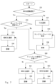
- Figure 6 shows an example of a haptic encoder selection scheme.
- the HAV data processing unit 113 determines whether the HAV data received by the reader terminal 110 is kinesthetic data (step S31).
- Kinesthetic data is data that includes data related to at least one of force, torque, or pressure. Furthermore, if the HAV data is not kinesthetic data, the HAV data is tactile data.
- Tactile data is data related to humans perceiving the surface of an object through their senses (e.g., data indicating the feel of the hand).
- the HAV data processing unit 113 determines whether the HAV data was transmitted via the first network 131 based on the selection of the encoder/decoder 114 used (step S32).
- the first network 131 is a network in which delays that would interfere with remote surgery do not occur in HAV communication.
- the second network 132 which is not the first network 131, is a network in which delays that could interfere with remote surgery may occur in HAV communication.
- the HAV data processing unit 113 selects NDHC as the encoder (step S33).
- NDHC is based on a Just Noticeable Difference (JND) encoder to reduce redundant data traffic.
- JND Just Noticeable Difference
- the HAV data processing unit 113 can train and optimize the NDHC encoder using network dynamics (step S34) to make the encoding of the HAV data more efficient.
- the network dynamics indicates the change over time of any parameter related to the communication quality of the HAV data detected by the HAV data processing unit 113 in the communication of the HAV data between the leader terminal 110 and the follower terminal 120.
- the parameters related to the communication quality include, but are not limited to, jitter, packet loss, packet errors, transmission delay, and bandwidth.
- the HAV data processing unit 113 can further train and optimize the NDHC encoder by utilizing feedback information from the network channel that is fed back to the NDHC encoder.
- the HAV data processing unit 113 selects WDHP as the encoder (step S35).
- WDHP is based on a combination of the Time-Domain Passivity Approach (TDPA) and a perceptual deadband (DB) coding scheme.
- TDPA Time-Domain Passivity Approach
- DB perceptual deadband
- TDPA encoding ensures the passivity of a two-port network, including communication channels that may cause communication failures.
- the signal transmissions on the leader and follower sides are attenuated to dissipate excess output energy, thereby supporting system stability and ensuring passivity.
- the HAV data processor 113 uses the WDHP scheme to utilize information about the network dynamics to train and optimize the encoding scheme in the presence of network delays and other signal transmission impairments (step S36). After training, the HAV data processor 113 can further train and optimize the WDHP encoder by utilizing feedback information from the network channel that is fed back to the WDHP encoder.
- the HAV data processing unit 113 selects TC (Tactile Codec) as the encoder (step S37). Haptic data has fewer communication requirements than kinesthetic data. Therefore, the HAV data processing unit 113 sets the sampling rate of TC by selecting a simple sampling scheme (step S38).
- the HAV data processor 113 also trains and optimizes the encoding scheme based on network dynamics (step S39). After training, the HAV data processor 113 can further train and optimize the TC encoder by utilizing feedback information from the network channel that is fed back to the TC encoder.
- the HAV data processing unit 113 determines whether the HAV data is kinesthetic data or haptic data, and functions as a change unit that changes the encoder used to communicate the HAV data based on the determination result.
- the HAV data processing unit 113 can select an appropriate encoder depending on the type of HAV data. Therefore, the HAV data processing unit 113 can accurately reproduce for the user the data received by the leader terminal 110, which can lead to improved QoE.
- the HAV data processing unit 113 can further determine the degree of delay that occurs in the network used for communication, and change the encoder used for communicating the HAV data based on the determined degree of delay. Therefore, the HAV data processing unit 113 can increase the accuracy with which the data received by the leader terminal 110 is reproduced for the user, leading to further improvement in QoE.
- the HAV data processing unit 113 may also perform the following process to further optimize the encoding of haptic data when network delays occur.
- FIG. 7 shows a different example of a haptic encoder selection scheme.
- the selected codec is changed depending on whether the delay is large or not. Note that the explanation of steps S31 to S34 and S37 to S39 in FIG. 7 is omitted because they are the same as those in FIG. 6. Also, in the following example, the leader terminal 110 is mainly explained, but the same processing can also be performed in the follower terminal 120.
- the HAV data processing unit 113 determines whether the transmission delay is large or not (step S40). For example, the HAV data processing unit 113 may determine whether the transmission delay is 1 ms or less, and determine that the delay is large if the delay is greater than 1 ms, and that the delay is medium if the delay is 1 ms or less. Note that a transmission delay of 1 ms or less means that the distance between the leader terminal 110 and the follower terminal 120 is approximately 150 km or less (approximately 300 km or less round trip distance).
- the HAV data processing unit 113 selects WDHC as the encoder (step S41). Furthermore, the HAV data processing unit 113 can make encoding of HAV data more efficient by training and optimizing the WDHC encoder using network dynamics (step S42). After training, the HAV data processing unit 113 can further train and optimize the WDHC encoder by utilizing feedback information from the network channel that is fed back to the WDHC encoder. Thus, the HAV data processing unit 113 can further improve the stability of remote operation on a wide area network.
- step S40 the HAV data processing unit 113 selects SEEHC as the encoder (step S43).
- SEEHC is a more preferable encoder than WDHC for solving delay issues when the transmission delay is large.
- the SE server 140 operates the second model 144 as a prediction model that supports SEEHC. This SEEHC enables the necessary functional units in the SE server 140.
- the HAV data processing unit 113 can use network dynamics to train and optimize the SEEHC encoder (step S44) to make encoding of HAV data more efficient. After training, the HAV data processing unit 113 can further train and optimize the SEEHC encoder by utilizing feedback information from the network channel that is fed back to the SEEHC encoder. Thus, the HAV data processing unit 113 can improve the stability of remote operation over a wide area network.
- the HAV data processing unit 113 can use any existing technology to determine whether a delay is occurring in the network or whether the delay that is occurring is large. For example, when HAV data is being transmitted between the leader terminal 110 and the follower terminal 120, the leader terminal 110 internally stores TFN (Time Frame Numbers) for the communication. The HAV data processing unit 113 measures the TFN at regular time intervals, for example, and detects the amount of change in the TFN to determine the occurrence and extent of a delay.
- the communication parameter that the HAV data processing unit 113 uses for the determination is not limited to the TFN.
- steps S33, S38, and S41 relate to network coding.
- step S43 is not the only step in which the necessary functional units in the SE server 140 are enabled.
- the SE server 140 can predict at least one of the network parameters or the user's behavior using at least one of the first functional unit 141 or the second functional unit 142.
- the follower terminal 120 can also execute processing similar to that shown in Figs. 6 and 7.
- the SE server 140 can also predict at least either the network parameters or the haptic data generated on the robot side, using at least either the first functional unit 141 or the second functional unit 142.
- the HAV data processing unit 113 may determine the encoder selection scheme shown in FIG. 6 or FIG. 7 using a trained model trained by using data including information indicating the type of HAV data and the degree of delay, and the corresponding encoder type (correct label) as training data.
- the SEEHC header transmitted from the transmitting unit (not shown) of the leader terminal 110 or the follower terminal 120 to the SE server 140 will be described.
- the HAV data processing unit 113 or the HAV data processing unit 123 generates and transmits a SEEHC header according to the selection result.
- the SE server 140 can operate the second model 144 and make predictions regarding the user or robot. Note that even if an encoder other than SEEHC is selected in FIG. 7, the leader terminal 110 or the follower terminal 120 can transmit a SEEHC header according to the selection result to the SE server 140.
- the HAV data processing unit 113 or the HAV data processing unit 123 can attach any type of SEEHC header shown below to the HAV data and transmit the HAV data to which the SEEHC header is attached.
- the leader terminal 110 is mainly described, but similar processing can also be performed on the follower terminal 120.
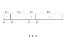
- FIG. 8 shows a specific example of a SEEHC header (codec header) that is used when the HAV data is kinesthetic data and it is determined in step S32 of FIG. 7 that there is no delay.
- the SEEHC header includes a T field H1, an F field H2, an X field H3, and an S field H4.
- the bit size of each field corresponds to delay information in the system.
- the delay information indicates, for example, whether or not there is a delay in the system.
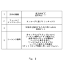
- FIG. 9 is a table explaining the SEEHC header coding corresponding to FIG. 8.
- the example of the SEEHC header shown in FIG. 9 is used when the HAV data received by the leader terminal 110 in FIG. 7 is kinesthetic data (Yes in step S31).
- the SEEHC header shown in FIG. 9 can be used regardless of the presence or absence of delay and the degree of delay.
- the X field H3 in FIG. 9 is the most important, as it is used to instruct advanced operations of the SE server 140. The configuration of each field will be explained in detail below with reference to FIG. 9.
- the T field H1 is 1 bit long and indicates the type of traffic flow direction.
- the F-field H2 is a syntax based on the encoder. Specifically, the F-field H2 contains details of the haptic data and is composed of 12 bits when there is no delay. The F-field H2 includes 3 bits for position, 3 bits for direction, 3 bits for velocity, and 3 bits for angular velocity. If there is no data related to force, the leader terminal 110 may fill the bit fields of the F-field H2 with 0 (zero). Note that the leader terminal 110 generates the F-field H2 based on data acquired from a sensor of the leader terminal 110 (e.g., a sensor attached to the user).
- a sensor of the leader terminal 110 e.g., a sensor attached to the user.
- the X field H3 is an extension bit used to indicate the function to be executed by the SE server 140.
- the X field H3 is 3 bits long.
- the HAV data processing unit 113 evaluates the QoE acquired by the QoE acquisition unit 115, and judges whether the QoE meets the required criteria. Based on the result of this judgment, the X field H3 is set to enable or disable the functions of the first functional unit 141 and the second functional unit 142 of the SE server 140. A detailed flow of this will be described later. Depending on the presence or absence of a transmission delay, or the degree of the delay, as judged in FIG. 7, the HAV data processing unit 113 can change and set the X field H3.
- the S field H4 is 32 bits long and contains the sequence number set by the leader terminal 110 when it transmits a packet of HAV data.
- the sequence number increases by one for each sampling step.
- the packet transmitted from the leader terminal 110 contains the latest sequence number.
- the difference between the TI system timestamp and the sequence number may be used for packet drop information.
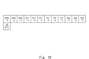
- FIG. 10 shows an example of the payload structure used in the SEEHC header in FIG. 8.
- FIG. 10 shows the payload structure of a forward bit stream.
- the payload is composed of fields for position data (pos-x, pos-y, pos-z), direction data (ori-x, ori-y, ori-z), velocity data (vel-x, vel-y, vel-z), and angular velocity data (ang-x, ang-y, ang-z), each of which indicates data in three-dimensional directions.
- the length of each field in the payload is 32 bits.
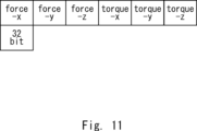
- FIG. 11 shows an example of the payload configuration of a feedback bit stream corresponding to the forward bit stream corresponding to FIG. 10.
- the feedback bit stream is composed of force data (force-x, force-y, force-z) and torque data (torque-x, torque-y, torque-z) each indicating data in three-dimensional directions.
- the length of each field in the feedback bit stream is 32 bits.
- the leader terminal 110 when a user of the leader terminal 110 performs an action, instructions regarding the action are transmitted from the leader terminal 110 to the follower terminal 120 as a forward bit stream as shown in FIG. 10.
- the follower terminal 120 controls a surgical robot connected to the follower terminal 120 based on the received instructions.
- the follower terminal 120 transmits data related to the force detected by a sensor provided on the robot to the leader terminal 110 as a feedback bit stream as shown in FIG. 11. Note that this feedback bit stream is transmitted directly from the follower terminal 120 to the leader terminal 110 if there is no transmission delay.
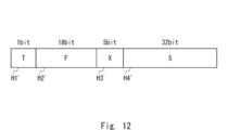
- FIG. 12 shows a specific example of a SEEHC header (codec header) that is used when the HAV data is kinesthetic data and it is determined in step S32 of FIG. 7 that there is a delay.
- the SEEHC header includes a T field H1', an F field H2', an X field H3', and an S field H4'. Below, for each field in FIG. 12, differences from FIG. 8 will be particularly described, and descriptions of commonalities with FIG. 8 will be omitted as appropriate.
- T field H1' is the same as T field H1 in Figure 8, so the explanation is omitted.
- the F-field H2' is a syntax based on the encoder. Specifically, the F-field H2' contains details of the haptic data and consists of 18 bits in the case of delay.
- the F-field H2' includes 3 bits for position, 3 bits for direction, 3 bits for velocity, and 3 bits for angular velocity.
- 6 bits are available in the F-field H2' for haptic/energy information corresponding to each dimension of the haptic data for TDPA.
- the haptic/energy information is information about at least one of haptic and energy.
- the haptic/energy information is used to control the codec in case of delay.
- the haptic/energy information is also used in the TDPA encoding process to prevent unexpected changes in data due to interference in the communication path. In this way, the energy level is minimized, and the system stability and passivity of the communication link are guaranteed. If there is no force-related data, the reader terminal 110 may fill the bit fields of the F-field H2' with 0 (zero
- the X field H3' is an extension bit used to indicate the function to be executed by the SE server 140.
- the X field H3 is 5 bits in length.
- the HAV data processing unit 113 sets the X field H3' to enable or disable the functions of the first functional unit 141 and the second functional unit 142 of the SE server 140 based on the QoE evaluation.
- the S field H4' is 32 bits long and contains the sequence number etc. set by the leader terminal 110 when sending the HAV data packet.
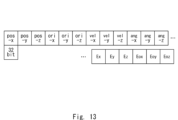
- Figure 13 shows an example of the payload structure used in the SEEHC header in Figure 12.
- Figure 13 shows the payload structure of a forward bit stream.
- the payload in Figure 13 includes additional information on translational energy (Ex, Ey, Ez) and rotational energy (Eox, Eoy, Eoz), which each indicate data in three-dimensional directions.
- the payload field length is 32 bits.
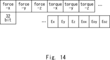
- Figure 14 shows an example of the payload configuration of a feedback bitstream corresponding to the forward bitstream corresponding to Figure 13.
- the feedback bitstream contains additional information regarding translational energies (Ex, Ey, Ez) and rotational energies (Eox, Eoy, Eoz), each of which indicates data in three dimensional directions.
- the new energy data for translational and rotational energy shown in Figures 13 and 14 is used in TDPA to level the output energy to maintain system stability and communication link passivity during remote operation when using a wide area network with delay. In this way, by adding information about the energy for controlling the codec to the SEEHC header, it becomes possible to maintain system stability and communication link passivity during remote operation.
- SEEHC takes advantage of the presence of SE server 140 in TI during remote operation and defines specific operations of SE server 140. Combining SE server 140 with SEEHC enhances TI functions. This improves and guarantees QoE in wide area networks, and supports low network latency in remote operation over distances of several hundred kilometers or more.
- SEEHC defines the bits within the SEEHC frame.
- the bits in the X field in particular are important as they define the operation of the SE server 140. As mentioned above, when there is no network delay, the bit size of the X field is 3 bits, but when there is a network delay, the bit size of the X field is 5 bits.
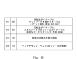
- FIG. 15 is a table showing actions associated with the SEEHC scheme when there is no delay.
- FIG. 15 shows an example of an X field with a bit size of 3 bits in the SEEHC header of FIG. 8. Below are examples of each action shown in FIG. 15.
- X11 When the X field is X11, i.e. "001", forwarding to the SE server 140 is enabled. Therefore, the leader terminal 110 transmits the HAV data that it had been transmitting to the follower terminal 120 to the SE server 140 instead of the follower terminal 120.
- X11 also indicates that the network prediction performed by the first functional unit 141 of the SE server 140 is enabled.
- the network prediction is, for example, a prediction regarding at least one of packet loss, transmission delay, QoS, QoE, and the like.
- X11 When the X field is X12, i.e. "011", transfer to the SE server 140 is enabled. Therefore, the leader terminal 110 transmits the HAV data that was previously transmitted to the follower terminal 120 to the SE server 140 instead of the follower terminal 120.
- X11 also indicates that the prediction (expert profile) of human behavior or haptic data acquired by a robot, performed by the second function unit 142 of the SE server 140, is enabled. This allows for advanced data modeling, prediction, and training. Then, the second function unit 142 performs the prediction and controls the HAV communication, thereby reducing packet loss and transmission delays, and improving QoS, QoE, etc.
- X11 corresponds to (B) in the first embodiment.
- X13 When the X field is X13, i.e., "101", it indicates that a procedure for detecting a new SE server 140 is being started. Determining a new SE server 140 may indicate that a new SE server 140 is being determined to control communications between the leader terminal 110 and the follower terminal 120 in a state in which the SE server 140 is not currently involved in the communications between the leader terminal 110 and the follower terminal 120. Alternatively, determining a new SE server 140 may indicate that a different SE server from the SE server currently controlling communications between the leader terminal 110 and the follower terminal 120 is being made to control communications. X13 is required, for example, when at least one of a QoS or QoE failure occurs on either the leader side or the follower side of the remote operation, and another SE with higher system resources may be required.
- the leader terminal 110 or the follower terminal 120 can have the new SE server 140 control the communications by sending a request including X13.
- the first functional unit 141 or the second functional unit 142 of the SE server 140 that receives the request starts controlling the communications of the HAV data in response to the request.
- the SE server that controls the communications can be changed from an unselected state to a selected state, or the SE server that controls the communications can be changed to a state where an SE server that can improve QoE, etc. is selected, thereby making it possible to improve the communications performance of the HAV data.
- X field is X14, or "111"
- the leader terminal 110 or the follower terminal 120 can release the resources of the SE server 140 that was being used by sending a trigger including X14 to that SE server 140.
- the first functional unit 141 or the second functional unit 142 of the SE server 140 releases the resources in response to the trigger.
- the SE server 140 is able to execute control of other communications, making it possible to improve communication performance not only between the leader terminal 110 and the follower terminal 120 but also throughout the entire network.
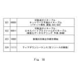
- FIG. 16 is a table showing actions related to the SEEHC scheme when there is a delay.
- FIG. 16 shows an example of an X field with a bit size of 5 bits in the SEEHC header of FIG. 12.
- the X field in FIG. 16 is X21, i.e., "00001”
- the X field in FIG. 16 is X22, i.e., "00011”
- it corresponds to when the X field in FIG. 15 is X12, i.e., "011”.
- the X field in FIG. 16 is X23, i.e., "10001”
- the SE server 140 For remote operation in the presence of delays, the SE server 140 needs to enable additional features to support a high level of QoE.
- the SE server 140 needs to be instructed to perform specific functions to reduce transmission delays, increase the QoE level, and maintain system stability (passivity of the communication link).
- the leader terminal 110 identifies the SEEHC by utilizing the X field shown in Figure 16.
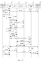
- FIG. 17 is a sequence diagram showing the SE server detection procedure started and executed by the leader terminal.
- a wide-area remote operation system is shown that includes a leader-side physical/virtual endpoint D1, a leader terminal D2, an SE server (1) D3, an SE server (n) D4, a follower terminal D5, and a follower-side physical/virtual endpoint D6.
- the leader terminal D2, the follower terminal D5, the SE server (1) D3, and the SE server (n) D4 correspond to the leader terminal 110, the follower terminal 120, and the SE server 140 in FIG. 5, respectively.
- the physical/virtual endpoint D1 corresponds to at least one of the physical environment 111 or the virtual environment 112 in FIG.
- the physical/virtual endpoint D6 corresponds to at least one of the physical environment 121 or the virtual environment 122 in FIG. 5.
- the physical/virtual endpoints D1 and D2 may be mounted on the leader terminal D2 and the follower terminal D5, respectively.
- the physical/virtual endpoints D1 and D2 may be separate devices from the leader terminal D2 and the follower terminal D5, respectively, and may be devices connected to the leader terminal D2 and the follower terminal D5.
- multiple SE servers, n in number are provided. The detection procedure will be described below with reference to FIG. 17.
- the physical/virtual endpoint D1 transmits the QoE performance (hereinafter also referred to as QoE(L)) on the leader side to the leader terminal D2 (step S54).
- the physical/virtual endpoint D1 notifies the leader terminal D2 that the QoE(L) does not meet the required standard. This notification is made, for example, by the user performing the remote operation operating the input unit of the physical/virtual endpoint D1.
- the leader terminal D2 starts detecting the SE server in response to the received notification, and transmits an indicator to the physical/virtual endpoint D1 notifying it that SE server detection has started (step S55). By transmitting this indicator, for example, processing such as stopping further data transmission from the physical/virtual endpoint D1 until the SE server is detected is performed.
- the leader terminal D2 starts the SE server detection process (step S56).
- the leader terminal D2 sends an SE server request (hereinafter also referred to as SE request) to all SE servers to which the leader terminal D2 can connect, including SE server (1) D3 and SE server (n) D4 (steps S57, S58).
- SE request has an SEEHC header including an X13 or X23 field, which means that a new SE server detection procedure is being started.
- the SE request is sent to candidates for SE servers that will execute control related to communications.
- SE server (1) D3 and SE server (n) D4 receive the SE request and send a response (hereinafter also referred to as SE response) to the leader terminal D2 (steps S59, S60).
- the leader terminal D2 selects an optimal SE server from among the SE servers that received the SE response, in place of the currently selected SE server, based on all the information necessary to select the optimal SE server (step S61).
- the leader terminal D2 may select the SE server that is closest to the leader terminal D2 on the communication path. However, the closest SE server may be in a busy state or may be under a high load. In that case, another SE server that can provide the necessary resources, such as the system load, the latency requirements of the HAV data, and the stability of the communication link, may be selected.
- the leader terminal D2 identifies an SE server that can provide the necessary resources according to the contents of the received SE response, and selects the identified SE server.
- the leader terminal D2 selects SE server (1) D3 as the optimal SE server
- the leader terminal D2 transmits a request to reserve resources (hereinafter also referred to as SE reservation) to the selected SE server (1) D3 (step S62).
- SE reservation a request to reserve resources
- the SE server (1) D3 checks whether there are any available resources in its own device.
- the SE server (1) D3 confirms that there are available resources, and transmits an SE response indicating that there are available resources to the leader terminal D2 (step S63).
- the leader terminal D2 In response to receiving the SE response from the SE server (1) D3, the leader terminal D2 notifies the follower terminal D5 of the selection of the SE server (1) D3 as the new SE server and transmits an SE handover request to execute a handover of the SE server (step S64).
- the follower terminal D5 transmits an SE reservation to the SE server (1) D3 indicated in the SE handover request (step S65).
- the SE server (1) D3 transmits an SE response to the follower terminal D5 (step S66).
- the follower terminal D5 which has received the SE response, transmits a handover response to the leader terminal D2 indicating that handover of the SE server is possible (step S67).
- the follower terminal D5 also notifies the physical/virtual endpoint D6 of an indicator indicating that the SE server to be used will be switched to SE server (1) D3 (selection result) (step S68).
- the leader terminal D2 which has received the handover response, recognizes that the SE server to be used can be switched to SE server (1) D3.
- the leader terminal D2 then notifies the physical/virtual endpoint D1 of an indicator indicating that the SE server to be used will be switched to SE server (1) D3 (step S69).
- the physical/virtual endpoint D1 resumes sending data related to remote operation to the leader terminal D2 (step S70).
- the leader terminal D2 transfers the received data to the selected SE server (1) D3 (step S71).
- the SE server (1) D3 analyzes the received data using a model held by the SE server and modifies the data. The details of this analysis and modification process are as described above.
- the SE server (1) D3 transmits the modified data to the follower terminal D5 (step S72).
- the follower terminal D5 transmits the received data to the physical/virtual endpoint D6 that is the target of the remote operation session (step S73).
- the data related to remote operation is modified by the operations up to this point and then transmitted to the physical/virtual endpoint D6.
- remote operation is performed as instructed by the user of the physical/virtual endpoint D1 and with adjustments made suitable for remote operation.
- the physical/virtual endpoint D1 transmits the QoE(L) to the leader terminal D2 (step S74).
- the physical/virtual endpoint D1 notifies the leader terminal D2 that the QoE(L) meets the required criteria. Therefore, the selection of a new SE server is not performed, and the selection of the SE server performed up to step S69 is completed. In other words, the remote operation between the physical/virtual endpoints D1 to D6 continues using the settings performed up to step S69. If the QoE(L) no longer meets the required criteria, the SE server selection process similar to that shown in steps S54 to S69 is started again.
- the leader terminal D2 may transmit to the SE server (1) D3, as a trigger to release the resources, an SEEHC header including a field X14 or X24 instructing the SE server (1) D3 to release the resources.
- steps S54 to S69 may be executed not only when a new SE server is selected, but also when at least one of the first functional unit 141 and the second functional unit 142 in an already selected SE server is enabled, disabled, or the settings are switched. In other words, this process may be executed when any change occurs in the method of controlling HAV communication based on at least one of the network parameters or predictions regarding humans or robots.
- FIG. 18 is a sequence diagram showing the SE server detection procedure that is initiated and executed by a follower terminal.
- the components of the remote control system shown in FIG. 18 are the same as those shown in FIG. 17. The detection procedure is explained below with reference to FIG. 18.
- the physical/virtual endpoint D1 transmits data related to the remote operation to the leader terminal D2 (step S81).
- the leader terminal D2 transfers the received data to the follower terminal D5 (step S82).
- the follower terminal D5 transfers the received data to the physical/virtual endpoint D6 that is the target of the remote operation session (step S83).
- the data related to the remote operation is transmitted to the physical/virtual endpoint D6, and the remote operation instructed by the user of the physical/virtual endpoint D1 is performed on the physical/virtual endpoint D6 side.
- the physical/virtual endpoint D6 transmits the QoE performance (hereinafter also referred to as QoE(F)) on the follower side to the follower terminal D5 (step S84).
- the physical/virtual endpoint D6 notifies the follower terminal D5 that the QoE(F) does not meet the required standard.
- This notification is made, for example, by a sensor on the follower side robot that is performing the instructed remote operation on-site detecting the QoE(F).
- this notification may be made by a user on the follower terminal D5 side operating the input unit of the physical/virtual endpoint D6.
- the follower terminal D5 starts detecting the SE server in response to the received notification, and transmits an indicator to the physical/virtual endpoint D6 notifying it that SE server detection has started (step S85). By transmitting this indicator, for example, processing such as stopping further data transmission from the physical/virtual endpoint D6 until the SE server is detected is performed.
- follower terminal D5 starts the SE server detection process (step S86).
- Follower terminal D5 sends an SE request to all SE servers to which follower terminal D5 can connect, including SE server (1) D3 and SE server (n) D4 (steps S87, S88).
- This SE request may have an SEEHC header including an X13 or X23 field, which indicates that a new SE server detection procedure is being started.
- SE server (1) D3 and SE server (n) D4 receive the SE request and send an SE response in response to it to follower terminal D5 (steps S89, S90).
- the follower terminal D5 selects the optimal SE server from among the SE servers from which the SE response was received, in place of the currently selected SE server (step S91). Details of the selection of the SE server by the follower terminal D5 are as explained in step S61.
- the follower terminal D5 selects the SE server (1) D3 as the optimal SE server
- the follower terminal D5 transmits an SE reservation to reserve resources to the SE server (1) D3 to be selected (step S92).
- the SE server (1) D3 checks whether there are any available resources in its own device.
- the SE server (1) D3 confirms that there are available resources, and transmits an SE response indicating that there are available resources to the follower terminal D5 (step S93).
- the follower terminal D5 In response to receiving the SE response from the SE server (1) D3, the follower terminal D5 notifies the leader terminal D2 of the selection of the SE server (1) D3 as the new SE server and transmits an SE handover request to execute a handover of the SE server (step S94).
- the leader terminal D2 transmits an SE reservation to the SE server (1) D3 indicated in the SE handover request (step S95).
- the SE server (1) D3 transmits an SE response to the leader terminal D2 (step S96).
- the leader terminal D2 which has received the SE response, transmits a handover response to the follower terminal D5 indicating that handover of the SE server is possible (step S97).
- the leader terminal D2 also notifies the physical/virtual endpoint D1 of an indicator indicating that the SE server to be used will be switched to SE server (1) D3 (selection result) (step S98).
- the follower terminal D5 which has received the handover response, recognizes that the SE server to be used can be switched to SE server (1) D3.
- the follower terminal D5 then notifies the physical/virtual endpoint D6 of an indicator indicating that the SE server to be used will be switched to SE server (1) D3 (step S99).
- the physical/virtual endpoint D1 resumes sending data related to remote operation to the leader terminal D2 (step S100).
- the leader terminal D2 transfers the received data to the selected SE server (1) D3 (step S101).
- the SE server (1) D3 analyzes the received data using a model held by the SE server and modifies the data. The details of this analysis and modification process are as described above.
- the SE server (1) D3 transmits the modified data to the follower terminal D5 (step S102).
- the follower terminal D5 transmits the received data to the physical/virtual endpoint D6 that is the target of the remote operation session (step S103).
- the data related to remote operation is modified by the operations up to this point and then transmitted to the physical/virtual endpoint D6.
- remote operation is performed as instructed by the user of the physical/virtual endpoint D1 and with adjustments made suitable for remote operation.
- the physical/virtual endpoint D6 transmits the QoE (F) to the follower terminal D5 (step S104).
- the physical/virtual endpoint D6 notifies the follower terminal D5 that the QoE (F) meets the required criteria. Therefore, the selection of a new SE server is not performed, and the selection of the SE server performed up to step S99 is completed. In other words, the remote operation between the physical/virtual endpoints D1 to D6 continues using the settings performed up to step S69. If the QoE (F) no longer meets the required criteria, the SE server selection process similar to that shown in steps S84 to S99 is started again.
- the follower terminal D5 may transmit to the SE server (1) D3, as a trigger to release the resources, an SEEHC header including a field X14 or X24 instructing the SE server (1) D3 to release the resources.
- steps S84 to S99 may be executed not only when a new SE server is selected, but also when at least one of the first functional unit 141 and the second functional unit 142 in an already selected SE server is enabled, disabled, or the settings are switched. In other words, this processing may be executed when any change occurs in the method of controlling HAV communication based on at least one of the network parameters or predictions regarding humans or robots.
- SE-EPS SE Expert Profile Selection
- expert profiles and templates initiated by the SE server 140 can be used to train the second model 144 of the SE server 140 to further optimize the QoE in teleoperation.
- the SE-EPS scheme supports performing haptic prediction such that the transmission delay is less than 1 ms when the prediction error is minimized.
- the SE-EPS scheme is a learning-by-demonstration approach in which a haptic sensing robot operated by teleoperation at the follower terminal 120 side acquires skills without being explicitly programmed.
- a hidden Markov model (HMM) is used for offline training by encoding the force and torque data and related parameters. Once the HMM is trained, a generalized profile can be extracted. HMMs are useful for predicting forward and feedback information that may be lost during data transmission over wide area networks.
- FIG. 19 is an image diagram showing training of the SE server 140 using an expert profile.
- the HMM may be trained by multiple experts.
- the expert E2 uses such objects to create an expert profile E3.
- the expert E2 uses the expert profile E3 to train the SE of the SE server E4. This makes the SE a trained agent, and the accuracy of the model is improved.
- the trained SE server E5 contributes to reducing transmission failures and delays by making predictions regarding the network and/or humans and/or robots.
- each object E11 there may be multiple objects E11 in the physical/virtual world E1, and each object E11 may be different. If each object E11 is different, then each object E11 requires a dedicated trainer E12 for training. As a result of training by the trainer E12, a different profile E13 is created for each object E11. For example, a surgeon can generate a remote operation profile E13 by using the dedicated trainer E12. A data profile related to the remote operation is also generated.
- position, direction, force and torque information is generated, and a set of data profiles is encoded by the HMM.
- the encoded data profiles are then sent to the SE E14.
- the generalized model is then reproduced during the online session by the trained SE E15.
- the profile E13 described above may be created, for example, outside the SE server 140 (for example, the leader terminal 110 or the follower terminal 120).
- the created profile E13 is input to the SE server E4, whereby the SE of the SE server E4 is trained.
- This training is performed, for example, when the SE server 140 is in passive mode (i.e., when at least one of the first model 143 and the second model 144 is not used).
- the SE server 140 is in active mode, i.e., when at least one of the first model 143 and the second model 144 is used, the above training may be performed as online training.
- the HMM is used to encode a set of force, torque and velocity data into a set of profiles.
- Gaussian Mixture Regression (GMR) can be used by the SE server E4 to support online remote operation sessions.
- GMR Gaussian Mixture Regression
- the SE server E4 can provide predicted data to the follower terminal 120 in case the leader terminal 110 data is lost or delayed. In this scenario, the transmission delay can be kept below 1 ms and the lost data can be restored.
- This HMM/GMR model is used to predict remote haptic feedback information, thereby reducing the error rate over a wide area network with prediction times of less than 1 ms.
- Multimodal data includes, for example, HAV data.
- Wide area networks have long wired and wireless connection links, which can adversely affect user experience.
- User experience is of high importance and is measured as QoE.
- Current remote control systems have limited scope of application and insufficient QoE in wide area networks. Therefore, remote control is mainly performed over short distances, such as within the same room or building, but is difficult to perform over long distances, such as between municipalities or countries.
- the user may face challenges such as delay or loss of HAV data due to the deterioration of QoE, which may cause the network to lose reliability.
- the communication link between the leader and followers does not affect remote control and can support system stability. For example, even when performing remote control over a long distance, such as between different municipalities or countries, it is desirable to have a state in which the QoE is indistinguishable or nearly indistinguishable from that of performing local remote control within the same room or building.
- the communication path (e.g., a path in a wireless connection such as 5G or 6G) should not interfere with the remote control itself.
- the remote control endpoint e.g., a leader terminal or a follower terminal
- the remote control endpoint is a very complex system including sensors, actuators, motors, springs, and dampers. Therefore, data transmission through the communication path may affect the stability of the system not only on the follower side but also on the leader side. For this reason, the remote control system needs to guarantee the system stability of the entire system.
- guaranteeing this system stability is a requirement that is difficult to achieve on a wide-area communication network. Specifically, data transmission on a wide-area network such as 5G or 6G may cause an unwanted increase in energy or a change in system impedance.
- Haptic data communication requires network latency of about 1 ms to properly control physical machines and virtual environments from remote locations.
- network latency of about 1 ms to properly control physical machines and virtual environments from remote locations.
- Technical constraints include not only latency in the wireless interface but also latency in the wired backbone network.
- Physical constraints result from the limited speed of light, which causes latency in wide area networks and limits the distance over which the network can be applied.
- haptic data includes different types of data: kinesthetic data and/or tactile data.
- Kinesthetic data includes data related to force, torque and pressure. These data are highly susceptible to transmission delays, jitter and packet loss. A delay or loss in the data signal can result in an event that is not perceptible to human perception. Furthermore, delays in kinesthetic data can lead to incorrect or delayed decision-making by human perception, i.e. the human brain. Even if a human senses kinesthetic data, which is an important signal, it may be ignored if the data reaches the human with a delay.
- Haptic data is data that allows humans to sense the surface of an object through their senses. Such data is less susceptible to transmission delays.
- audio and video data are combined with haptic data, synchronization of the haptic data, audio data and video data is important to achieve a high level of QoE. Therefore, it is important that HAV data transmission is supported with high network bandwidth, low latency and low jitter times.
- the remote control system 100 can reduce the transmission latency of HAV data over a wide area network such as 5G (e.g., 5G Advanced) or 6G, for example, having a distance of 100 km or more. Therefore, it is possible to support haptic applications such as remote control.
- 5G e.g., 5G Advanced
- 6G 6G
- the network of the remote control system 100 switches data traffic between the leader terminal and the follower terminals, thereby supplying data to an SE that provides a function of improving QoE for remote users, thereby achieving the above effect.
- the SE has an internal module (first functional unit 141) that predicts network parameters, and an internal module (second functional unit 142) that makes predictions about the user or robot.
- the SE can improve traffic quality and make the system in which remote control is realized more stable by predicting network parameters using the first functional unit 141.
- the SE can predict human behavior using the second functional unit 142, and instantly feed back predicted user behavior or information on haptic data acquired by the robot to the remote control system before new system data is transmitted to the SE. Therefore, the SE can improve QoE on a wide area network without being affected by network delays.
- the terminal in embodiment 2 can identify whether an SE server exists and whether such an SE server can support a remote control session.
- the SE server then supports the remote control session by receiving HAV data from the leader terminal and forwards the HAV data to the follower terminal.
- the SE server can also support the remote control session by receiving HAV data from the follower terminal and forward the HAV data to the leader terminal.
- the SE server has several modes: (1) The SE server can be in a passive mode in which it does not modify the HAV data received from the leader terminal and transfers the HAV data from the leader terminal to the follower terminals. In this passive mode, the second function unit 142 of the SE server is disabled, so that the SE server does not perform predictions about users or robots.
- the SE server When the SE server receives HAV data from the leader terminal, it can also be in an active mode in which it modifies the HAV data and transfers the modified data to the follower terminal. In this active mode, the second functional unit 142 of the SE server is active, so the SE server makes predictions about the user or robot and modifies the received HAV data based on the prediction results.
- the SE server can also apply additional functions and techniques, such as prediction, to the data being sent and received. This prediction allows the SE to improve QoE performance.
- the SE server can use trained expert models, network predictions, or additional encoding schemes to predict human actions or haptic data acquired by a robot, further reducing network latency or improving overall QoE performance.
- the SE server can obtain advanced prediction models by performing training using the SE-EPS.
- the first functional unit 141 of the SE server 140 may be enabled or disabled.
- the SE server 140 can improve the data transmission performance (or the accuracy of the network prediction) by predicting network parameters.
- the first functional unit 141 and the second functional unit 142 of the SE server 140 can be individually set to enable or disable the functions as needed.
- either the first functional unit 141 or the second functional unit 142 of the SE server 140 may be set to enable, or both may be set to enable.
- SEs with different functions such as prediction, remote rendering, or computation outsourcing may be provided in the network.
- Each SE may provide a unique set of functions to be used during a remote operation session.
- a specific SE selection procedure is described for selecting the most appropriate SE.
- This SE selection is part of an encoding scheme for indicating the internal functions of the selected SE server 140.
- the SEEHC indicates the SE regarding the prediction functions and provides data fields for setting the functions on the SE, leader, and follower side.
- devices with low power consumption and functions such as remote rendering and computation outsourcing can be provided in the network as SEs. Therefore, even if the functions in the network are expanded, the increase in power consumption required for the network can be suppressed.
- FIG. 20 is a diagram showing the effects of the present disclosure.
- the leader terminal 110 is connected to the follower terminal 120 via the SE server 140.
- the configurations of the leader terminal 110 and the follower terminal 120 are as shown in FIG. 5, and description thereof will be omitted.
- the SE server 140 also includes a rendering/modeling unit 14A, a prediction unit 14B, and an interface 14C.
- the rendering/modeling unit 14A is a functional unit collectively referring to the first functional unit 141 and the second functional unit 142
- the prediction unit 14B is a functional unit collectively referring to the first model 143 and the second model 144.
- the interface 14C also corresponds to the interface 145.
- the leader terminal 110 has a coverage area (hereinafter also referred to as area A) in which data transmission from the leader terminal 110 is possible, which is determined by a data connection link LA (hereinafter also referred to as link LA).
- area A a coverage area in which data transmission from the leader terminal 110 is possible
- link LA (hereinafter also referred to as link LA).
- link LA crosses horizon HA, which is the boundary of area A
- link A becomes unstable, lossy, or has delays.
- the QoE (L) of the leader terminal 110 In the area beyond the horizon HA from the leader terminal 110, it is not realistic to use the QoE (L) of the leader terminal 110 for the QoE adjustment function, which is a function of link LA.
- FIG. 20 the fact that QoE (L) cannot be used for the QoE adjustment function in the area beyond the horizon HA is shown as event F1.
- the follower terminal 120 has a coverage area (hereinafter also referred to as area B) in which data transmission from the follower terminal 120 is possible, which is determined by the data connection link LB (hereinafter also referred to as link LB).
- area B the data connection link LB
- link LB the data connection link LB
- link LB crosses horizon HB, which is the boundary of area B
- link B becomes unstable, has high loss, or experiences delays.
- the QoE (F) of the follower terminal 120 it is not realistic to use the QoE (F) of the follower terminal 120 for the QoE adjustment function, which is a function of link LB.
- event F2 the fact that QoE (F) cannot be used for the QoE adjustment function in the area beyond horizon HB is shown as event F2.
- the leader terminal 110 obtains not only the QoE(L) but also the QoE(F) at the follower terminal 120 and detects the difference between the QoE(L) and the QoE(F). For example, if the detection result indicates a network failure, the leader terminal 110 starts negotiation with the SE server 140 to select a new SE server 140. If the link LB exceeds the horizon HB, the follower terminal 120 can perform the same process instead of the leader terminal 110. In this way, it is possible to perform a determination of the network performance at both the leader terminal 110 and the follower terminal 120. This enables predictive models, outsourced rendering, or modeling.
- the SE Server 140 supports remote operations over wide area networks by predicting network performance metrics and human activity, thereby ensuring the required latency parameters and enabling life-critical operations such as remote surgery. Thus enabling stable and reliable TI for HAV application scenarios. Furthermore, high reliability and low latency communication for smart factors, industrial Internet-of-Things (IoT) and telemedicine.
- IoT Internet-of-Things
- the present disclosure may be fully embodied as a V2V (Virtual to Virtual) environment in which a communication link including an SE becomes a network.
- V2V Virtual to Virtual
- human behavior and the acquisition of that behavior data may be performed in a virtual space using Google Glass (registered trademark) or HoloLens (registered trademark), etc.
- the leader terminal transmits data regarding the behavior, etc. performed in the virtual space to the follower terminal, and at that time, the SE server can predict human behavior, etc. Therefore, the SE server can provide data at any time when lost data occurs.
- the SE server can also fully render an entire session based only on basic data input from the leader terminal. This is interesting for multi-game operations, since the expendable and costly rendering of graphics can be managed by the SE server. For example, Finite Element Method simulations and 3D (Three Dimensions) rendering require powerful Graphical Units (GPUs). GPUs can be stored in large quantities on the SE server, like a so-called rendering farm, allowing the SE server to perform rendering in multi-game operations, etc. The disclosed system can therefore be applied in outsourced graphical rendering applications, including AI graphical rendering models, and monetized.
- the servers and terminals described in each embodiment of this disclosure are applicable to remote medical care, remote surgery, remote robotic surgery, robotic surgery, etc., for the purpose of, for example, biopsy, injection, neurosurgery, or cancer treatment, but the applications are not limited to these.
- This disclosure is used, for example, for emulation between a human and a machine located at a distance, using a reinforcement learning unit supervised for remote operation.
- Ultra-low latency wide area network support enables secure remote operation across large distances over wide area communication networks for applications such as proactive healthcare, industrial automation, intelligent transportation, and surveillance for defense and disaster management.
- the remote location communications disclosed herein enables a number of edutainment applications and immersive human experiences via remote machines, including immersive virtual/augmented reality (VR/AR).
- the disclosure also enables immersive control and manipulation of real and virtual objects and machines.
- An AI-enhanced server on the access network enables prediction of haptic manipulation, including offline expert training and online simulation of haptic manipulation using haptic recognition, kinesthetic recognition, or tactile recognition.
- the present disclosure can support remote master and replica pair control, including sensing and control of real and virtual machines and robots, as well as predictive HAV data.
- the present disclosure can also support haptic internet applications, including smart factories and smart logistics.
- At least one of the terminals or servers shown in each embodiment is realized by one or more computers.
- the method of distributing each part of the terminal or server among the multiple computers is arbitrary.
- Some or all of the components of the terminal or server may be provided in a cloud server constructed on the cloud, or in other types of virtualized servers generated using virtualization technology, etc. Functions other than those provided in servers such as cloud servers or virtualized servers are placed at the edge. For example, in a wide area network that realizes remote surgery, the edge is a device placed at or near the site of the surgery.
- this disclosure has been described as a hardware configuration, but this disclosure is not limited to this.
- the processes or steps executed by at least any of the terminals, management servers, and SE servers described in the above embodiment may be realized by having a processor in a computer execute a computer program.
- FIG. 21 is a block diagram showing an example of the hardware configuration of an information processing device in which the processing of the device in each of the above-described embodiments is executed.
- this information processing device 90 includes a signal processing circuit 91, a processor 92, and a memory 93.
- the signal processing circuit 91 is a circuit for processing signals according to the control of the processor 92.
- the signal processing circuit 91 may also include a communication circuit for receiving signals from a transmitting device.
- the processor 92 is connected or coupled to the memory 93, and performs the processing of the device described in the above-mentioned embodiment by reading and executing software or computer programs from the memory 93.
- Examples of the processor 92 include a CPU (Central Processing Unit), an MPU (Micro Processing Unit), an FPGA (Field-Programmable Gate Array), a DSP (Demand-Side Platform), and an ASIC (Application Specific Integrated Circuit).
- a single processor may be used as the processor 92, or multiple processors may be used in cooperation with each other.
- Memory 93 may be composed of volatile memory, non-volatile memory, or a combination of both.
- the volatile memory may be, for example, a RAM (Random Access Memory) such as DRAM (Dynamic Random Access Memory) or SRAM (Static Random Access Memory).
- the non-volatile memory may be, for example, a ROM (Read Only Memory) such as PROM (Programmable Read Only Memory) or EPROM (Erasable Programmable Read Only Memory), flash memory, or an SSD (Solid State Drive).
- a single memory may be used as memory 93, or multiple memories may be used in cooperation with each other.
- the memory 93 is used to store one or more instructions.
- the one or more instructions are stored in the memory 93 as a group of software modules.
- the processor 92 can perform the processing described in the above embodiment by reading and executing these groups of software modules from the memory 93.
- the memory 93 may include memory built into the processor 92 in addition to memory provided outside the processor 92.
- the memory 93 may also include storage located away from the processors that make up the processor 92.
- the processor 92 can access the memory 93 via an I/O (Input/Output) interface.
- processors in each device in the above-mentioned embodiments execute one or more programs including a set of instructions for causing a computer to execute the algorithm described in the drawings. This processing enables the information processing described in each embodiment to be realized.
- the program includes instructions (or software code) that, when loaded into a computer, cause the computer to perform one or more functions described in the embodiments.
- the program may be stored on a non-transitory computer-readable medium or tangible storage medium.
- computer-readable medium or tangible storage medium may include random-access memory (RAM), read-only memory (ROM), flash memory, solid-state drive (SSD) or other memory technology, CD-ROM, digital versatile disk (DVD), Blu-ray® disk or other optical disk storage, magnetic cassette, magnetic tape, magnetic disk storage or other magnetic storage device.
- the program may be transmitted on a transitory computer-readable medium or communication medium.
- transitory computer-readable medium or communication medium may include electrical, optical, acoustic, or other forms of propagated signals.
- Appendix 1 a receiving unit that receives haptic data from another terminal connected via a network; a generation unit that generates instruction information for a management server on the network to execute control regarding the communication of the haptic data with the other terminal based on an indicator indicating a communication state of the haptic data; a transmitting unit configured to transmit the instruction information to the management server.
- the generation unit predicts a parameter related to a network between the terminal and the other terminal, addressed to the management server, based on the index, and generates the instruction information for controlling communication between the terminal and the other terminal, based on the predicted parameter.
- the terminal according to claim 1. the generation unit predicts haptic data to be generated on the other terminal side based on the index, and generates the instruction information for controlling the management server to change the content of the haptic data to be transmitted to the terminal based on the predicted haptic data and transmit the changed content to the terminal.
- the generation unit generates a request for newly detecting the management server that executes control regarding communication of the haptic data with the other terminal based on the indicator; The transmission unit transmits the request to candidates for the management server to be changed.
- a terminal according to any one of appendix 1 to 3. (Appendix 5)
- the generation unit generates a trigger for releasing resources of the management server,
- the transmission unit transmits the trigger to the management server.
- the change unit further determines a degree of delay occurring in a network used for the communication, and changes an encoder used for communicating the haptic data based on the determined degree of delay. 7.
- the terminal according to claim 6. If the haptic data is kinesthetic data, the modification unit further determines whether or not there is a delay in a network used for the communication, and if there is a delay, adds information about energy for controlling a codec to a header of the haptic data compared to a case where there is no delay, and transmits the header to the other terminal. 8.
- (Appendix 9) a receiving unit that receives, from a second terminal that is connected to a first terminal via a network and receives haptic data from the first terminal, instruction information for executing control regarding communication of the haptic data with the first terminal; a control execution unit that executes control regarding communication of the haptic data based on the instruction information;
- a management server comprising: (Appendix 10) The control execution unit predicts a parameter related to a network between the first terminal and the second terminal based on the instruction information, and controls communication between the first terminal and the second terminal based on the predicted parameter. 10.
- the control execution unit predicts haptic data to be generated on the first terminal side based on the instruction information, and controls the haptic data to be transmitted to the second terminal to be changed based on the predicted haptic data and transmitted to the second terminal.
- the management server according to claim 9 or 10.
- the receiving unit receives a request from the second terminal to execute control regarding communication of the haptic data with the first terminal; the control execution unit starts control related to communication of the haptic data in response to the request.
- the management server according to any one of appendix 9 to 11.
- the receiving unit receives a trigger for releasing resources of the management server from the second terminal, the control execution unit releases resources of the management server in response to the trigger. 13.
- the management server according to any one of appendix 9 to 12.
- Appendix 14 A terminal, A management server;
- the terminal includes: a receiving unit that receives haptic data from another terminal connected via a network; a generation unit that generates instruction information for the management server on the network to execute control regarding the communication of the haptic data with the other terminals based on an indicator indicating a communication state of the haptic data; a transmission unit that transmits the instruction information to the management server,
- the management server includes: A receiving unit that receives the instruction information from the terminal; a control execution unit that executes control regarding communication of the haptic data based on the instruction information.
- the generation unit predicts a parameter related to a network between the terminal and the other terminal, addressed to the management server, based on the index, and generates the instruction information for controlling communication between the terminal and the other terminal, based on the predicted parameter;
- the control execution unit predicts a parameter related to a network between the terminal and the other terminal based on the instruction information, and controls communication between the terminal and the other terminal based on the predicted parameter.
- the generation unit predicts haptic data to be generated on the other terminal side based on the index, and generates the instruction information for controlling the management server to change the content of the haptic data to be transmitted to the terminal based on the predicted haptic data, and to transmit the changed content to the terminal;
- the control execution unit predicts haptic data to be generated on the other terminal side based on the instruction information, and controls the haptic data to be transmitted to the terminal to be changed based on the predicted haptic data and transmitted to the terminal.
- (Appendix 17) Receive haptic data from other devices connected via the network; generating instruction information for a management server on the network to execute control regarding the communication of the haptic data with the other terminal based on an indicator indicating a communication state of the haptic data; transmitting the instruction information to the management server; The way a computer does something. (Appendix 18) receiving, from a second terminal that is connected to a first terminal via a network and receives haptic data from the first terminal, instruction information for executing control regarding communication of the haptic data with the first terminal; and executing control regarding communication of the haptic data based on the instruction information. The way a computer does something.
- (Appendix 19) Receive haptic data from other devices connected via the network; generating instruction information for a management server on the network to execute control regarding the communication of the haptic data with the other terminal based on an indicator indicating a communication state of the haptic data; transmitting the instruction information to the management server; A program that causes a computer to do something. (Appendix 20) receiving, from a second terminal that is connected to a first terminal via a network and receives haptic data from the first terminal, instruction information for executing control regarding communication of the haptic data with the first terminal; and executing control regarding communication of the haptic data based on the instruction information. A program that causes a computer to do something.
- Terminal 11 Receiving unit 12 Generating unit 13 Transmitting unit 20 Management server 21
- Receiving unit 22 Control execution unit 100
- Remote operation system 110 Leader terminal 111 Physical environment 112 Virtual environment 113 HAV data processing unit 114 Encoder/decoder 115 QoE acquisition unit 120
- Follower terminal 121 Physical environment 122 Virtual environment 123 HAV data processing unit 124 Encoder/decoder 125 QoE acquisition unit 130
- Network 131 First network 132 Second network 140 SE server 141 First function unit 142 Second function unit 143 First model 144 Second model 145 Interface
Landscapes
- Engineering & Computer Science (AREA)
- Multimedia (AREA)
- Signal Processing (AREA)
- General Engineering & Computer Science (AREA)
- Theoretical Computer Science (AREA)
- Human Computer Interaction (AREA)
- Physics & Mathematics (AREA)
- General Physics & Mathematics (AREA)
- Computer Networks & Wireless Communication (AREA)
- Information Transfer Between Computers (AREA)
Priority Applications (1)
| Application Number | Priority Date | Filing Date | Title |
|---|---|---|---|
| JP2025544194A JPWO2025052844A1 (cg-RX-API-DMAC7.html) | 2023-09-05 | 2024-08-07 |
Applications Claiming Priority (2)
| Application Number | Priority Date | Filing Date | Title |
|---|---|---|---|
| JP2023-143543 | 2023-09-05 | ||
| JP2023143543 | 2023-09-05 |
Publications (1)
| Publication Number | Publication Date |
|---|---|
| WO2025052844A1 true WO2025052844A1 (ja) | 2025-03-13 |
Family
ID=94923734
Family Applications (1)
| Application Number | Title | Priority Date | Filing Date |
|---|---|---|---|
| PCT/JP2024/028166 Ceased WO2025052844A1 (ja) | 2023-09-05 | 2024-08-07 | 端末、管理サーバ、通信システム、方法及びプログラム |
Country Status (2)
| Country | Link |
|---|---|
| JP (1) | JPWO2025052844A1 (cg-RX-API-DMAC7.html) |
| WO (1) | WO2025052844A1 (cg-RX-API-DMAC7.html) |
Cited By (1)
| Publication number | Priority date | Publication date | Assignee | Title |
|---|---|---|---|---|
| JP7876749B1 (ja) * | 2025-06-16 | 2026-06-22 | C1株式会社 | 無人移動体操縦システム、情報処理装置、プログラム、および情報処理方法 |
Citations (4)
| Publication number | Priority date | Publication date | Assignee | Title |
|---|---|---|---|---|
| JP2006033396A (ja) * | 2004-07-15 | 2006-02-02 | Sony Corp | 送信装置、受信装置、通信システム、送信方法、受信方法、送信プログラム、受信プログラム及びサーバ装置 |
| JP2014049850A (ja) * | 2012-08-30 | 2014-03-17 | Sumitomo Electric Ind Ltd | 双方向対話システム |
| WO2021124902A1 (ja) * | 2019-12-17 | 2021-06-24 | ソニーグループ株式会社 | 情報処理装置および方法 |
| JP2022180139A (ja) * | 2021-05-24 | 2022-12-06 | 日本放送協会 | 配信ビットレート決定装置およびそのプログラム |
-
2024
- 2024-08-07 WO PCT/JP2024/028166 patent/WO2025052844A1/ja not_active Ceased
- 2024-08-07 JP JP2025544194A patent/JPWO2025052844A1/ja active Pending
Patent Citations (4)
| Publication number | Priority date | Publication date | Assignee | Title |
|---|---|---|---|---|
| JP2006033396A (ja) * | 2004-07-15 | 2006-02-02 | Sony Corp | 送信装置、受信装置、通信システム、送信方法、受信方法、送信プログラム、受信プログラム及びサーバ装置 |
| JP2014049850A (ja) * | 2012-08-30 | 2014-03-17 | Sumitomo Electric Ind Ltd | 双方向対話システム |
| WO2021124902A1 (ja) * | 2019-12-17 | 2021-06-24 | ソニーグループ株式会社 | 情報処理装置および方法 |
| JP2022180139A (ja) * | 2021-05-24 | 2022-12-06 | 日本放送協会 | 配信ビットレート決定装置およびそのプログラム |
Cited By (1)
| Publication number | Priority date | Publication date | Assignee | Title |
|---|---|---|---|---|
| JP7876749B1 (ja) * | 2025-06-16 | 2026-06-22 | C1株式会社 | 無人移動体操縦システム、情報処理装置、プログラム、および情報処理方法 |
Also Published As
| Publication number | Publication date |
|---|---|
| JPWO2025052844A1 (cg-RX-API-DMAC7.html) | 2025-03-13 |
Similar Documents
| Publication | Publication Date | Title |
|---|---|---|
| Torres Vega et al. | Immersive interconnected virtual and augmented reality: A 5G and IoT perspective | |
| US12231483B1 (en) | Extended and mixed reality experience adaptation, processing, and handover from one edge node to another | |
| US11076181B2 (en) | Systems and methods for resolving manifest file discontinuities | |
| CN113966596B (zh) | 用于数据流量路由的方法和设备 | |
| US11914489B2 (en) | Redundant control in a distributed automation system | |
| US20210374573A1 (en) | Method and Devices for Latency Compensation | |
| CN118348882B (zh) | 一种基于数字孪生的锂电池生产线故障监控系统及方法 | |
| CN119358637B (zh) | 基于边端协同的模型训练方法及相关设备 | |
| CN119692432A (zh) | 利用基础模型蒸馏的联邦学习 | |
| CN116781343A (zh) | 一种终端可信度的评估方法、装置、系统、设备及介质 | |
| Odema et al. | Testudo: Collaborative intelligence for latency-critical autonomous systems | |
| Koucheryavy et al. | A first-priority set of telepresence services and a model network for research and education | |
| CN121478120A (zh) | 一种基于因果不变性的元宇宙虚实交互方法 | |
| CN115051931A (zh) | 一种基于强化学习的虚拟化身迁移方法及其控制系统 | |
| US20190037422A1 (en) | Systems and methods for improving content presentation | |
| WO2025102785A1 (en) | Method, apparatus, system and readable storage medium for time series analysis | |
| CN120046549A (zh) | 基于量子预测的电气仿真交互方法及系统 | |
| CN121195267A (zh) | 用于更新双侧模型的装置、方法和计算机程序 | |
| JP7841613B2 (ja) | 推定装置、学習装置、推定方法、学習方法、及びプログラム | |
| KR102833425B1 (ko) | Vr 모션 예측 장치 | |
| Nakayima et al. | Impact of Network Complexity, Mobility Models, and Wireless Technologies on SDN-DTN Performance in Internet of Vehicles (IoV) Environments | |
| WO2024013894A1 (ja) | 遠隔制御システム、遠隔制御方法、および遠隔制御プログラム | |
| Herrero et al. | Transforming Digital Twins into Cognitive Digital Twins to Enable Future Manufacturing | |
| US20260112098A1 (en) | AR Ecosystem | |
| CN120785985B (zh) | 基于泛函网络的语音通话实时评价方法及装置、设备及存储介质 |
Legal Events
| Date | Code | Title | Description |
|---|---|---|---|
| 121 | Ep: the epo has been informed by wipo that ep was designated in this application |
Ref document number: 24862498 Country of ref document: EP Kind code of ref document: A1 |
|
| ENP | Entry into the national phase |
Ref document number: 2025544194 Country of ref document: JP Kind code of ref document: A |
|
| WWE | Wipo information: entry into national phase |
Ref document number: 2025544194 Country of ref document: JP |
|
| NENP | Non-entry into the national phase |
Ref country code: DE |