WO2025047125A1 - ガス状体の温度測定方法および温度測定装置 - Google Patents
ガス状体の温度測定方法および温度測定装置 Download PDFInfo
- Publication number
- WO2025047125A1 WO2025047125A1 PCT/JP2024/024483 JP2024024483W WO2025047125A1 WO 2025047125 A1 WO2025047125 A1 WO 2025047125A1 JP 2024024483 W JP2024024483 W JP 2024024483W WO 2025047125 A1 WO2025047125 A1 WO 2025047125A1
- Authority
- WO
- WIPO (PCT)
- Prior art keywords
- light
- temperature
- light source
- intensity
- gas
- Prior art date
- Legal status (The legal status is an assumption and is not a legal conclusion. Google has not performed a legal analysis and makes no representation as to the accuracy of the status listed.)
- Pending
Links
Images


Classifications
-
- G—PHYSICS
- G01—MEASURING; TESTING
- G01K—MEASURING TEMPERATURE; MEASURING QUANTITY OF HEAT; THERMALLY-SENSITIVE ELEMENTS NOT OTHERWISE PROVIDED FOR
- G01K11/00—Measuring temperature based upon physical or chemical changes not covered by groups G01K3/00, G01K5/00, G01K7/00 or G01K9/00
- G01K11/12—Measuring temperature based upon physical or chemical changes not covered by groups G01K3/00, G01K5/00, G01K7/00 or G01K9/00 using changes in colour, translucency or reflectance
-
- G—PHYSICS
- G01—MEASURING; TESTING
- G01K—MEASURING TEMPERATURE; MEASURING QUANTITY OF HEAT; THERMALLY-SENSITIVE ELEMENTS NOT OTHERWISE PROVIDED FOR
- G01K11/00—Measuring temperature based upon physical or chemical changes not covered by groups G01K3/00, G01K5/00, G01K7/00 or G01K9/00
- G01K11/12—Measuring temperature based upon physical or chemical changes not covered by groups G01K3/00, G01K5/00, G01K7/00 or G01K9/00 using changes in colour, translucency or reflectance
- G01K11/18—Measuring temperature based upon physical or chemical changes not covered by groups G01K3/00, G01K5/00, G01K7/00 or G01K9/00 using changes in colour, translucency or reflectance of materials which change translucency
Definitions
- This disclosure relates to a method and device for measuring the temperature of a gaseous medium.
- VOCs flammable hydrocarbon gases
- gas visualization technology is a convenient method for detecting distant gas leaks when the conditions are right, it has the problem that quantitative measurement is difficult. This is because the way gas appears is affected not only by concentration but also by temperature. Even if the gas detection strength is simply measured, the concentration cannot be calculated if the gas temperature is not known.
- the temperature of leaked gas can generally be considered to be room temperature.
- the concentration is measured on the assumption that the gas temperature can generally be considered to be the same as the surrounding air temperature. Alternatively, it is assumed that the gas temperature will be obtained using a separate temperature sensor if necessary.
- CO2 is a gas emitted as a result of combustion of raw gas such as VOC. Therefore, the temperature of CO2 to be measured is often higher than room temperature. CO2 is also contained in human breath, and in that case, it is emitted at a temperature close to the body temperature of the human body. Furthermore, in the future, quantitative measurement of leakage from pipes through which high-concentration CO2 is pumped will also be required for the recovery, reuse, and underground burial of CO2 . In that case, the temperature of CO2 will drop due to the sudden expansion of the leaked CO2 outside the pipe, so it will be necessary to measure CO2 at a temperature lower than room temperature.
- the temperature of the gas to be measured varies depending on the type of gas.
- VOCs which can be considered room temperature
- quantitative measurement of gases at various temperatures will be required. To do this, a method for determining the gas temperature is important.
- Patent Document 2 proposes a method of optically determining the gas temperature using a laser by focusing on multiple absorption wavelengths that have different temperature dependencies of the gas.
- a method that uses a large-scale and expensive laser system just to measure this temperature is a practical method.
- the method for measuring the temperature of a gaseous body includes: 1.
- a method for measuring the temperature of a gaseous body absorbing light A of wavelength ⁇ A comprising the steps of: A light source L A capable of emitting light A with varying light intensity; providing an optical sensor S A capable of receiving light A and measuring the intensity of the received light; A light source L A and an optical sensor S A are arranged so that the gaseous substance is present on a light path of light A emitted from the light source L A and received by the optical sensor S A ; The light intensity is changed and light A is emitted from the light source L A , and the light intensity received by the light sensor S A is measured.
- the temperature measuring device for a gaseous body comprises: 1.
- An apparatus for measuring the temperature of a gaseous body absorbing light A of wavelength ⁇ A comprising: a light receiving device including a detection element in which an optical sensor capable of receiving light A and measuring the intensity of the received light is disposed, an imaging optical system, and a band pass filter; a light source that emits light in a wavelength band including light A; a light intensity varying device that varies the light intensity of the light source; a signal processing device that processes signals from the light receiving device; and an integrated control device that controls both the light intensity varying device and the signal processing device;
- the signal processing device has a function of determining the light intensity I min(t) of the light source at which the time fluctuation width of the measured light intensity is minimized, and a function of calculating the equivalent temperature T S of the light source for the light intensity I min(t) of the light source by approximating the emission spectrum of the light source with perfect blackbody radiation.
- the present disclosure provides a temperature measurement device that can easily measure the temperature of a gaseous body located at a remote location using a small, portable, and simple device, as well as a method for using the same and a method for measuring temperature.
- FIG. 11 is a characteristic diagram showing the relationship between optical density and detected light intensity when the light source equivalent temperature is equal to the gas temperature.
- FIG. 13 is a characteristic diagram showing a detected light intensity spectrum when the light source equivalent temperature is equal to the gas temperature.
- 10 is a characteristic diagram showing the relationship between the difference in signal intensity of light that has passed through a gaseous body relative to light that has not passed through a gaseous body and the light source equivalent temperature.
- FIG. FIG. 1 is a flow chart diagram illustrating a method for measuring temperature according to the present disclosure. 13 is a typical gas visualization image during the light source equivalent temperature rise. 13 is a typical gas visualization image during the decrease in the light source equivalent temperature.
- FIG. 11 is a characteristic diagram showing the change over time in detection intensity in a gas passing region and when no gas is present.
- 10 is a characteristic diagram showing a time change in a time differential signal of a detected light intensity in a gas passing region.
- FIG. 10 is a characteristic diagram showing a time change in a time differential signal of a detected light intensity in a gas passing region.
- a ⁇ B in the text means greater than or equal to A and less than or equal to B.
- the temperature measuring device (temperature measuring system) 101 has a light source 11, a light source intensity varying device (intensity varying device) 12, an integrated control device 13, a light receiving device 14 consisting of a camera 15, and an image processing device 19.
- the temperature measuring device 101 has a light receiving device 14 consisting of an optical sensor 16, a lens 17, and a band pass filter 18 instead of the camera 15, and a signal processing device 20.
- the lens 17 is an imaging optical system that forms an image of a gaseous material 21 on the light receiving portion of the optical sensor 16.
- the size of the light source 11 may be a large-area planar light source that covers the entire gaseous body, or a small-area light source that illuminates only a part of the gaseous body.
- the blackbody radiation equivalent temperature (hereinafter sometimes referred to as "equivalent temperature") of the light emitted by the light source 11 must have a range of change that covers a range from equivalent temperatures higher than the temperature of the gas to equivalent temperatures lower than the temperature of the gas.
- the gaseous material 21 is not particularly limited as long as it is a gas that absorbs light in a specific wavelength range.
- one gas selected from the group consisting of methane (CH 4 ), carbon dioxide (CO 2 ), carbon monoxide (CO), nitrous oxide (N 2 O), nitric oxide ( NO ), nitrogen dioxide (NO 2 ), sulfur dioxide (SO 2 ), sulfur trioxide (SO 3 ), water vapor (H 2 O), ammonia (NH 3 ), sulfur hexafluoride (SF 6 ), and fluorocarbons can be mentioned. These gases are particularly in high demand as measurement targets.
- the gaseous material 21 may be a gas that absorbs ultraviolet light, visible light, and terahertz light.
- the light intensity varying device 12 is a device that changes the intensity of the light emitted from the light source 11, for example, by the following (1) to (5).
- (1) Control of power supply to the light source 11 (2) Variable transmittance filtering using two linear polarizing filters (3) Filtering using neutral density filters with different transmittances (4) Continuously variable neutral density filter (5) Variable aperture
- the wavelength band of light reaching the optical sensor from the light source it is preferable to limit the wavelength band of light reaching the optical sensor from the light source to the vicinity of the optical absorption band of the gaseous body.
- the vicinity of the optical absorption band refers to a wavelength band that includes the wavelength ⁇ A of the light A absorbed by the gaseous body 21 and is approximately equal to the band of the gas absorption band spectrum of the gaseous body.
- the band of the gas absorption band spectrum refers to 1/10 full width of the absorption coefficient of the gas, including the wavelength ⁇ A of the light A. It is more preferable that the wavelength band near the optical absorption band is 0.25 to 4 times the band of the gas absorption band spectrum of the gaseous body.
- the means for limiting the wavelength can be (1) a bandpass filter that transmits only a certain wavelength range with high efficiency, or (2) a combination of a spectroscope with a built-in diffraction grating or prism and a slit that transmits only a specific wavelength range with high efficiency.
- the light source or the optical sensor itself is a narrowband element, it may be used as the means for limiting the wavelength.
- the light receiving device 14 is a device that receives light from the light source 11 and outputs a light receiving signal.
- Examples of the light receiving device 14 include a (2D) image system shown in FIG. 1 and a one-pixel detection system shown in FIG. 18.
- the light receiving device 14 of the (2D) image system can be composed of a camera 15 including an image sensor (light sensor) 16, a lens 17, and a bandpass filter 18, as shown in FIG. 1.
- the light receiving device 14 of the one-pixel detection system can be composed of a photodetector (light sensor) 16, a lens 17, and a bandpass filter 18, as shown in FIG. 18.
- the light receiving device 14 can be a (2D) image system (FIG. 1) or a one-pixel detection system (FIG. 18).
- the light receiving device 14 (FIG. 1) of the (2D) image system is composed of an infrared camera 15 including an infrared imaging element (optical sensor) 16, an infrared lens 17, and a bandpass filter 18.
- the light receiving device 14 (FIG. 18) of the one-pixel detection system is composed of an infrared detector (optical sensor) 16, an infrared lens 17, and a bandpass filter 18.
- a one-pixel detection system has the advantage that it is a simple system and can be easily reduced in cost.
- the infrared lens 17 there are no particular restrictions on the infrared lens 17, so long as it has sufficient imaging performance as a camera.
- the optical system for example, (1) a lens imaging system using optical lenses made of Ge, Si, ZnSe, ZnS, or sapphire, (2) a reflective optical system using a mirror, and (3) a composite optical system using both a mirror and a lens can be used.
- the optical lens may be a short focal length lens or a zoom lens.
- magnification, F-number, allowable aberration, etc. of the optical lens and they may be appropriately selected in consideration of cost, ease of use, weight, resolution, field of view, etc.
- the infrared imaging element (optical sensor) 16 is a pixel-shaped infrared sensor having multiple light-receiving pixels, and any light-receiving element having sensitivity in the above wavelength band can be used without any particular restrictions. In other words, this light-receiving element is a light-receiving element that detects light that matches the absorption wavelength of the gas to be measured.
- a photoelectric conversion element such as InSb, HgCdTe, InAs/GaSb superlattice, InGaAs/InAlAs quantum well, or GaAs/AlGaAs quantum well can be used.
- the infrared imaging element 16 a thermal infrared light sensing element using a bolometer, thermopile, or pyroelectric element may also be used.
- the pixels of the infrared imaging element 16 are arranged in a matrix.
- the pixel size and number of pixels of the infrared imaging element 16 There is no particular limit to the pixel size and number of pixels of the infrared imaging element 16. If the pixel size is reduced, the size of the infrared imaging element 16 also becomes smaller, and the infrared lens 17 can also be easily miniaturized. If the pixel size is large, it becomes easier to improve the sensitivity and S/N ratio, and it becomes easier to increase the resolution.
- the pixel size may be, for example, 10 ⁇ 10 to 30 ⁇ 30 ⁇ m2 .
- the number of pixels may be set appropriately in consideration of the size of the device, the required resolution, and the like.
- the number of pixels may be, for example, 64 ⁇ 64 to 1920 ⁇ 1536.
- the bandpass filter 18 can be used without any particular restrictions as long as it selectively transmits light in the above wavelength band.
- a multilayer film made of SiO, ZnS, and Ge formed on a sapphire or germanium substrate can be used as the bandpass filter 18.
- the bandpass filter can be placed either in front of the infrared lens 17 or behind the infrared lens 17 when viewed from the infrared imaging element 16. Placing the bandpass filter in front of the infrared lens 17 has the advantage that the bandpass filter can be easily replaced or removed. Placing the bandpass filter behind the infrared lens 17 has the advantage that the bandpass filter can be smaller and that it can be cooled together with the infrared imaging element 16 when cooling as described below.
- the infrared imaging element 16 and the bandpass filter 18 are preferably cooled.
- By cooling noise caused by thermal radiation from the environment, components, etc. can be reduced.
- the bandpass filter 18 is at room temperature, the thermal radiation from the bandpass filter 18 is superimposed on the signal of the infrared imaging element 16 as a large baseline. As a result, the contrast of the obtained image is significantly reduced.
- Examples of cooling methods include Stirling coolers, Peltier elements, and liquid nitrogen cooling. Stirling coolers and Peltier elements are preferably used because they are easy to handle. In particular, Stirling coolers are particularly preferably used because they are handy, can be cooled to below 80K, and can be operated with batteries.
- the cooling temperature is preferably 50K or higher and 250K or lower.
- the noise level can be improved by one order of magnitude or more.
- the noise level drops by more than 20 orders of magnitude compared to when used at room temperature, and noise due to other factors such as voltage fluctuations becomes dominant.
- optical sensor 16, etc. are described here as being for infrared light, which is a typical example. However, it is preferable that the optical sensor 16, etc. has a wavelength band that matches the absorption wavelength of the gas to be measured. Therefore, optical sensors 16, etc. for at least infrared light, visible light, ultraviolet light, and terahertz light are used depending on the gas.
- the image processing device 19 is a device that performs the following processes (1) to (3).
- (1) The signal received and captured by the infrared imaging element 16 is processed to obtain fluctuations in the spatial distribution of light intensity (image fluctuations).
- (2) The light intensity I min of the light source 11 at which the spatial distribution fluctuation width is minimized is obtained.
- (3) The equivalent temperature Ts of the light source 11 for the light intensity Imin is calculated by approximating the emission spectrum of the light source 11 with perfect blackbody radiation.
- Specific hardware examples of the image processing device 19 include computers such as mobile PCs.
- Mobile PCs are small, lightweight, easy to move around, and easy to use.
- the infrared detector (optical sensor) 16 of the one-pixel system can be any light receiving element that is sensitive to the above wavelength band, as in the 2D image system, without any particular restrictions.
- photoelectric conversion elements such as InSb, HgCdTe, InAs/GaSb superlattice, InGaAs/InAlAs quantum well, and GaAs/AlGaAs quantum well can be used as the infrared detector 16.
- a thermal infrared sensing element using a bolometer, thermopile, or pyroelectric element can also be used as the infrared detector 16.
- the pixel size of the infrared detector 16 can be increased, and the S/N ratio can be improved.
- a typical infrared sensor is described as the optical sensor 16.
- the optical sensor 16 has a wavelength band that matches the absorption wavelength of the gas to be measured. Therefore, an optical sensor 16 for at least one of infrared light, visible light, ultraviolet light, and terahertz light is used depending on the gas.
- the signal processing device 20 is a device that performs the following processes (1) to (3).
- (1) The light reception signal of the infrared detector 16 is processed to obtain the time fluctuation of the light intensity.
- the light intensity I min (t) of the light source 11 at which the time fluctuation width is minimized is obtained.
- (3) The equivalent temperature Ts of the light source 11 for the light intensity Imin (t) is calculated by approximating the emission spectrum of the light source 11 with perfect blackbody radiation.
- Specific hardware for the signal processing device 20 can be a computer such as a mobile PC.
- a mobile PC is small, lightweight, easy to move around, and easy to use.
- the integrated control device 13 is a device that controls the light intensity variable device 12 and the image processing device 19 or the signal processing device 20 to perform measurements.
- the integrated control device 13 mediates between this measurement and obtaining the above-mentioned light intensity I min or light intensity I min(t) .
- Specific hardware of the integrated control device 13 can be a computer such as a mobile PC.
- a single computer can be equipped with the integrated control device 13 and the image processing device 19 or the signal processing device 20, and is small and easy to use.
- infrared light is emitted from a light source 11, passes through a gas, where a portion of the light is absorbed or enhanced, passes through a bandpass filter having a pass wavelength band near the absorption wavelength of the gas, and is incident on and detected by an infrared imaging element.
- Infrared light is often absorbed and its intensity reduced when it passes through a gas.
- infrared light of the same wavelength can appear to have a higher intensity (become enhanced) when it passes through a different gas (gas in a different state). This is because the light emitted from the gas is added to the infrared light.
- the intensity of the infrared light passing through the gaseous body 21 changes significantly depending on the relationship between the blackbody radiation equivalent temperature (equivalent temperature) of the infrared light from the light source 11 and the temperature of the gaseous body 21. That is, if the temperature of the gaseous body 21 is lower than the equivalent temperature of the infrared light, the infrared light is absorbed by the gaseous body 21, and the intensity of the infrared light passing through the gaseous body 21 becomes smaller. On the other hand, if the temperature of the gaseous body 21 is higher than the equivalent temperature of the infrared light, the infrared light is enhanced by the emission from the gaseous body 21.
- the intensity of the infrared light passing through the gaseous body 21 changes significantly at the point where the equivalent temperature of the infrared light and the temperature of the gaseous body 21 become equivalent. Therefore, by changing the equivalent temperature of the infrared light, the temperature of the gaseous body 21 can be identified from the equivalent temperature when the intensity of the infrared light passing through the gaseous body 21 changes significantly.
- the temperature of the gaseous body 21 is obtained based on the change in the intensity of infrared light corresponding to the equivalent temperature of the infrared light. Furthermore, to improve the accuracy of the temperature, the time point at which the intensity of the infrared light changes is obtained more precisely by taking into account fluctuations in the change in the intensity of the infrared light. Details of this will be described later.
- the emission spectrum of a light source can be approximated by perfect blackbody radiation I b ( ⁇ , T s ) at temperature T s .
- the temperature T s at this time is called the equivalent temperature of the light source.
- changing the intensity of the light source corresponds to changing the equivalent temperature T s of the light source.
- ⁇ is the wavelength.
- the first term on the right side of equation (1) indicates that light with intensity I b ( ⁇ , T s ) incident on the gas from the light source is exponentially attenuated due to absorption in the gas.
- ⁇ g ( ⁇ , T g , c, L) is the optical density of the gas and is expressed by the following equation (3).
- ⁇ ( ⁇ , T g ) is the absorption coefficient per concentration of the gas.
- the absorption coefficient ⁇ ( ⁇ , T g ) varies greatly with ⁇ , and is large around the absorption wavelength of the gas.
- the absorption coefficient ⁇ ( ⁇ , T g ) also changes with the gas temperature T g .
- the absorption coefficient ⁇ ( ⁇ , T g ) increases as the gas concentration c increases and as the gas thickness L increases.
- the second term on the right hand side of equation (1) represents the light intensity emitted by the gas, and indicates that as the optical density of the gas increases, the light intensity asymptotically approaches a constant intensity I b ( ⁇ , T g ), which is the radiant intensity of a perfect black body at temperature T g .
- This light intensity I d0 ( ⁇ , T s ) is the detected light intensity in the background region where the light source is directly visible when the field of view of the infrared camera in Figure 1 contains a mixture of (1) a background region where the light source is directly visible, and (2) a gas passage region where the light source is visible through gas.
- an infrared imaging element that is, an infrared detector having a plurality of pixels arranged therein, is used as the optical sensor SA .
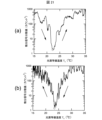
- FIGs 14(a) and (b) show the time change of the average brightness in Figure 12(a) during heating and cooling, respectively, as a function of the light source equivalent temperature Ts .
- This average brightness is the average brightness in a rectangular frame (40 pixels horizontally and 32 pixels vertically arranged at the center of the image) in which gas is constantly observed, as shown in Figure 12(a).
- the average brightness in Figure 14 indicates the brightness difference of the gas passage area with respect to a representative location of the background area, which corresponds to formula (6) and Figure 10.
- a moving average of 1.0 s before and after is applied to the average brightness (brightness difference).
- Figures 15 and 16 show the central difference images obtained from the images in the previous and following frames of the image of interest for Figures 12 and 13, respectively.
- the central difference image I m is an image obtained by averaging, for each pixel, the brightness (luminance) of images I ⁇ 1 and I +1 in the frames before and after the image I 0 of interest, and is calculated using the following formula.
- the central difference image may be referred to as a “difference image.”
- I m (I ⁇ 1 +I +1 )/2
- I -1 Brightness (luminance) of the image (pixel) in the frame immediately before the image I0 of interest
- I +1 Brightness (luminance) of the image (pixel) in the frame one after the image I0 of interest
- the light source used, the method for measuring the light source temperature, the CO2 gas supply conditions, the nozzle used, and the light source temperature settings are the same as in Example 1.
- an InSb detector with a pixel of 120 ⁇ m on a side was used as the infrared detector.
- a bandpass filter with a wavelength band of [4.12 ⁇ m, 4.33 ⁇ m] was placed in front of the detector.
- a specific point in the gas passage area was imaged on the detector using an infrared lens with a focal length of 50 mm and an F value of 2.5.
- Figures 20(a) and (b) show the time changes in the AC component extracted by time differentiation of the signal when the temperature is rising and falling, respectively. In both cases, the AC component becomes very small at a certain point, and it can be seen that at that point the brightness of the background area and the area through which gas passes is reversed.
- the determination accuracy is lower in the second embodiment, and the results vary greatly depending on the signal processing method. This shows the usefulness of using an image sensor as a detector.
- the present disclosure can be applied as is by using a light source and optical sensor that are matched to the absorption wavelength of the gas of interest.
- a method for measuring the temperature of a gaseous body includes: 1.
- a method for measuring the temperature of a gaseous body absorbing light A of wavelength ⁇ A comprising the steps of: A light source L A capable of emitting light A with a variable light intensity and a light sensor S A capable of receiving the light A and measuring the intensity of the received light are provided;
- the light source L A and the optical sensor S A are arranged so that the gaseous material is present on a light path of light A emitted from the light source L A and received by the optical sensor S A ; measuring the intensity of light received by the optical sensor S A when light A is emitted from the light source L A with a varying light intensity; From the measurement of the received light intensity, a light intensity I min of the light source L A when a spatial and/or temporal fluctuation width of the received light intensity is minimized is obtained; Calculating an equivalent temperature T S of the light source L A with respect to the light intensity I min when the emission spectrum of the
- a method for measuring the temperature of a gaseous body according to a second aspect of the present disclosure includes the steps of:
- the optical sensor SA is a pixel sensor having a plurality of light-receiving pixels.
- the temperature measuring method for a gaseous body according to aspect 3 of the present disclosure is the same as that of aspect 2,
- the plurality of light-receiving pixels are arranged in a matrix.
- a method for measuring the temperature of a gaseous body according to a fourth aspect of the present disclosure includes any one of the first to third aspects, An imaging optical system is disposed so that an image of the gaseous material is formed on the light receiving portion of the optical sensor SA .
- a method for measuring the temperature of a gaseous body according to a fifth aspect of the present disclosure includes any one of the first to fourth aspects,
- the fluctuation width is calculated from the variance value of a differential signal obtained by time-differentiating the light reception signal of the optical sensor SA .
- a method for measuring the temperature of a gaseous body includes any one of the first to fifth aspects, a wavelength band of light reaching the optical sensor S from the light source L is limited to a wavelength band of light A by one or more selected from the group consisting of the light source L , the optical sensor S , and a bandpass filter; The width of the wavelength band is 0.25 to 4 times the width of the gas absorption band spectrum of the gaseous material.
- a method for measuring the temperature of a gaseous body according to a seventh aspect of the present disclosure includes any one of the first to sixth aspects, A reflecting mirror is disposed on the light path.
- a method for measuring the temperature of a gaseous body according to an eighth aspect of the present disclosure includes any one of the first to seventh aspects,
- the light source LA is an infrared light source.
- a method for measuring the temperature of a gaseous body includes any one of the first to eighth aspects,
- the gaseous material contains one gas selected from the group consisting of methane ( CH4 ), carbon dioxide ( CO2 ), carbon monoxide (CO), nitrous oxide ( N2O ), nitric oxide ( NO ), nitrogen dioxide ( NO2 ), sulfur dioxide ( SO2 ), sulfur trioxide (SO3), water vapor ( H2O ), ammonia ( NH3 ), sulfur hexafluoride ( SF6 ) and fluorocarbons.
- a method for measuring the temperature of a gaseous body according to a tenth aspect of the present disclosure includes any one of the first to eighth aspects,
- the light source L A emits light having a light absorption band including a plurality of types of gaseous substances,
- a bandpass filter array including a plurality of bandpass filters having different center wavelengths is disposed in front of the light receiving surface of the optical sensor SA .
- a temperature measuring device for a gaseous body includes: 1.
- An apparatus for measuring the temperature of a gaseous body absorbing light A of wavelength ⁇ A comprising: a camera having an image sensor including a plurality of optical sensors capable of receiving light A and measuring the intensity of the received light, an imaging optical system, and a bandpass filter; A light source that emits light in a wavelength band including the wavelength ⁇ A ; a light intensity varying device for varying the light intensity of the light source; An image processing device; an integrated control device that controls both the light intensity variable device and the image processing device,
- the image processing device includes: Based on the signal output from the camera, a light intensity I min of the light source at which the spatial and/or temporal fluctuation width of the measured light intensity is minimized is calculated; The equivalent temperature T S of the light source with respect to the light intensity I min of the light source is calculated by approximating the emission spectrum of the light source with perfect blackbody radiation.
- a gaseous body temperature measuring device is the same as the eleventh aspect, the signal output from the camera includes image information representing a temporal change in distribution of the light intensity of the light passing through the gaseous body;
- the spatial fluctuation width is calculated from the variance value of a difference image (for example, a central difference image) which is the difference between a plurality of the images having a time difference.
- a temperature measuring device for a gaseous body includes: 1.
- An apparatus for measuring the temperature of a gaseous body absorbing light A of wavelength ⁇ A comprising: a light receiving device including a detection element in which an optical sensor capable of receiving light A and measuring the intensity of the received light is disposed, an imaging optical system, and a bandpass filter; a light source that emits light in a wavelength band including light A; a light intensity varying device for varying the light intensity of the light source; A signal processing device that processes a signal of the light receiving device; an integrated control device that controls both the light intensity variable device and the signal processing device;
- the signal processing device includes: A light intensity I min (t) of the light source at which the time fluctuation width of the measured light intensity is minimized is obtained; The equivalent temperature T S of the light source with respect to the light intensity I min (t) of the light source is calculated by approximating the emission spectrum of the light source with perfect blackbody radiation.
- a gaseous body temperature measuring device is the device according to the thirteenth aspect,
- the time fluctuation width is calculated as an AC component extracted by time differentiation of the light reception signal output from the light receiving device.
- the present disclosure makes it possible to easily measure the temperature of a gaseous body located at a distance.
- the device is small and easy to carry, making it very easy to use as it can be moved around and easily installed and used in various locations. Moreover, real-time measurement is possible.
- Light source 12 Light intensity variable device 13: Integrated control device 14: Light receiving device 15: Camera (infrared camera) 16: Optical sensor (infrared imaging element, infrared detector) 17: Lens (infrared lens) 18: Bandpass filter 19: Image processing device 20: Signal processing device 21: Gas (gaseous substance) 101: Temperature measurement system 102: Temperature measurement system
Landscapes
- Physics & Mathematics (AREA)
- General Physics & Mathematics (AREA)
- Investigating Or Analysing Materials By Optical Means (AREA)
Priority Applications (2)
| Application Number | Priority Date | Filing Date | Title |
|---|---|---|---|
| JP2025542765A JPWO2025047125A1 (https=) | 2023-08-30 | 2024-07-05 | |
| CN202480039703.7A CN121336092A (zh) | 2023-08-30 | 2024-07-05 | 气状物的温度测定方法及温度测定装置 |
Applications Claiming Priority (2)
| Application Number | Priority Date | Filing Date | Title |
|---|---|---|---|
| JP2023139522 | 2023-08-30 | ||
| JP2023-139522 | 2023-08-30 |
Publications (1)
| Publication Number | Publication Date |
|---|---|
| WO2025047125A1 true WO2025047125A1 (ja) | 2025-03-06 |
Family
ID=94818705
Family Applications (1)
| Application Number | Title | Priority Date | Filing Date |
|---|---|---|---|
| PCT/JP2024/024483 Pending WO2025047125A1 (ja) | 2023-08-30 | 2024-07-05 | ガス状体の温度測定方法および温度測定装置 |
Country Status (3)
| Country | Link |
|---|---|
| JP (1) | JPWO2025047125A1 (https=) |
| CN (1) | CN121336092A (https=) |
| WO (1) | WO2025047125A1 (https=) |
Citations (4)
| Publication number | Priority date | Publication date | Assignee | Title |
|---|---|---|---|---|
| JP2005164453A (ja) * | 2003-12-04 | 2005-06-23 | Toyota Motor Corp | 空間温度計測装置および方法 |
| JP2009174990A (ja) * | 2008-01-24 | 2009-08-06 | Nec Corp | ガス測定装置およびガス測定方法 |
| JP2012058093A (ja) * | 2010-09-09 | 2012-03-22 | Mitsubishi Electric Building Techno Service Co Ltd | ガス漏れ検出装置 |
| US20210310941A1 (en) * | 2018-12-20 | 2021-10-07 | Flir Systems Ab | Gas lens filter systems and methods |
-
2024
- 2024-07-05 WO PCT/JP2024/024483 patent/WO2025047125A1/ja active Pending
- 2024-07-05 CN CN202480039703.7A patent/CN121336092A/zh active Pending
- 2024-07-05 JP JP2025542765A patent/JPWO2025047125A1/ja active Pending
Patent Citations (4)
| Publication number | Priority date | Publication date | Assignee | Title |
|---|---|---|---|---|
| JP2005164453A (ja) * | 2003-12-04 | 2005-06-23 | Toyota Motor Corp | 空間温度計測装置および方法 |
| JP2009174990A (ja) * | 2008-01-24 | 2009-08-06 | Nec Corp | ガス測定装置およびガス測定方法 |
| JP2012058093A (ja) * | 2010-09-09 | 2012-03-22 | Mitsubishi Electric Building Techno Service Co Ltd | ガス漏れ検出装置 |
| US20210310941A1 (en) * | 2018-12-20 | 2021-10-07 | Flir Systems Ab | Gas lens filter systems and methods |
Also Published As
| Publication number | Publication date |
|---|---|
| JPWO2025047125A1 (https=) | 2025-03-06 |
| CN121336092A (zh) | 2026-01-13 |
Similar Documents
| Publication | Publication Date | Title |
|---|---|---|
| US6297504B1 (en) | Method and apparatus for the imaging of gases | |
| Williams | Thermal imaging cameras: characteristics and performance | |
| US11624704B2 (en) | Filter incidence narrow-band infrared spectrometer | |
| US9513166B2 (en) | Split field spectral imager | |
| US20140336953A1 (en) | Method to quantify emission rates in atmospheric plumes | |
| CN105466491B (zh) | 基于双通道分子滤光的成像式燃烧温度浓度测量装置 | |
| Dai et al. | A novel image-guided FT-IR sensor using chalcogenide glass optical fibers for the detection of combustion gases | |
| Naranjo et al. | IR gas imaging in an industrial setting | |
| Wang et al. | Compensation method for infrared temperature measurement of explosive fireball | |
| CN108139272B (zh) | 用于气体及火焰检测与成像及测量的单一装置及其漂移校正方法 | |
| JP2004361383A (ja) | 化学的及び生物学的物質の検出及び分析 | |
| CN217358878U (zh) | 一种在线式危化气体泄漏遥测设备 | |
| CN105044110B (zh) | 一种二氧化硫气体成像遥测方法与装置 | |
| Kastek et al. | Infrared imaging fourier transform spectrometer as the stand-off gas detection system | |
| Zhou et al. | Remote sensing monitoring system for ship exhaust using infrared multispectral imaging | |
| US12313535B2 (en) | Filter incidence narrow-band infrared spectrometer | |
| Olbrycht et al. | Gas identification and estimation of its concentration in a tube using thermographic camera with diffraction grating | |
| WO2025047125A1 (ja) | ガス状体の温度測定方法および温度測定装置 | |
| Li et al. | Prelaunch spectral calibration of a carbon dioxide spectrometer | |
| Kastek et al. | Hyperspectral imaging infrared sensor used for enviromental monitoring | |
| Amon et al. | Evaluation of thermal imaging cameras used in fire fighting applications | |
| Paulec et al. | Tomographic reconstruction of a jet engine exhaust plume using an infrared hyperspectral imager | |
| Brunzendorf | Small Burning Hydrogen Leaks in Industrial Plants: A Comparison of UV and IR Remote Imaging Detection | |
| Olbrycht | Thermal Contrast Model for Optical Gas Imaging Performance Analysis | |
| Major et al. | Chemical vapor detection using a passive infrared bioinspired sensor |
Legal Events
| Date | Code | Title | Description |
|---|---|---|---|
| 121 | Ep: the epo has been informed by wipo that ep was designated in this application |
Ref document number: 24859170 Country of ref document: EP Kind code of ref document: A1 |
|
| ENP | Entry into the national phase |
Ref document number: 2025542765 Country of ref document: JP Kind code of ref document: A |
|
| WWE | Wipo information: entry into national phase |
Ref document number: 2025542765 Country of ref document: JP |