WO2025041262A1 - Emc filter and charging system - Google Patents
Emc filter and charging system Download PDFInfo
- Publication number
- WO2025041262A1 WO2025041262A1 PCT/JP2023/030148 JP2023030148W WO2025041262A1 WO 2025041262 A1 WO2025041262 A1 WO 2025041262A1 JP 2023030148 W JP2023030148 W JP 2023030148W WO 2025041262 A1 WO2025041262 A1 WO 2025041262A1
- Authority
- WO
- WIPO (PCT)
- Prior art keywords
- charging
- power line
- connector
- emc filter
- conversion adapter
- Prior art date
- Legal status (The legal status is an assumption and is not a legal conclusion. Google has not performed a legal analysis and makes no representation as to the accuracy of the status listed.)
- Pending
Links
Images


Classifications
-
- B—PERFORMING OPERATIONS; TRANSPORTING
- B60—VEHICLES IN GENERAL
- B60L—PROPULSION OF ELECTRICALLY-PROPELLED VEHICLES; SUPPLYING ELECTRIC POWER FOR AUXILIARY EQUIPMENT OF ELECTRICALLY-PROPELLED VEHICLES; ELECTRODYNAMIC BRAKE SYSTEMS FOR VEHICLES IN GENERAL; MAGNETIC SUSPENSION OR LEVITATION FOR VEHICLES; MONITORING OPERATING VARIABLES OF ELECTRICALLY-PROPELLED VEHICLES; ELECTRIC SAFETY DEVICES FOR ELECTRICALLY-PROPELLED VEHICLES
- B60L53/00—Methods of charging batteries, specially adapted for electric vehicles; Charging stations or on-board charging equipment therefor; Exchange of energy storage elements in electric vehicles
- B60L53/10—Methods of charging batteries, specially adapted for electric vehicles; Charging stations or on-board charging equipment therefor; Exchange of energy storage elements in electric vehicles characterised by the energy transfer between the charging station and the vehicle
- B60L53/14—Conductive energy transfer
- B60L53/16—Connectors, e.g. plugs or sockets, specially adapted for charging electric vehicles
Definitions
- This disclosure relates to EMC filters and charging systems.
- charging stations installed at the destination may be used for charging. If the charging station has a different standard from the standard that the electric vehicle complies with, a conversion adapter is used (see, for example, Patent Document 1, Patent Document 2, and Patent Document 3).
- the EMC filter disclosed herein is an EMC filter that suppresses common mode noise generated in power lines, and is connected between a vehicle's charging inlet and a charging cable connected to a charging station, and is detachable from a conversion adapter that connects the power lines of the charging inlet and the charging cable.
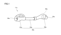
- FIG. 1 is a schematic perspective view illustrating an appearance of a conversion adaptor included in a charging system according to a first embodiment of the present disclosure.
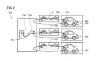
- FIG. 2 is a schematic diagram of the charging system according to the first embodiment of the present disclosure.
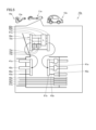
- FIG. 3 is a schematic diagram showing a connection state of electrical power lines and the like during charging by the charging system.
- FIG. 4 is a schematic diagram illustrating the EMC filter according to the first embodiment.
- FIG. 5 is a schematic diagram showing a state in which the EMC filter is attached to the second charging connector.
- FIG. 6 is a schematic diagram showing a state in which the EMC filter according to the second embodiment is attached to a charging inlet of a vehicle.
- An electric vehicle is provided with an EMC filter that is connected to a charging station and suppresses common mode noise generated when charging.
- a conversion adapter is used to convert the interface.
- an EMC filter is designed for an electric vehicle assuming that the vehicle will be connected to a charging station of the same charging method.
- the impedance component seen from the charging inlet of the electric vehicle toward the charging station changes compared to when the conversion adapter is not used, which causes a problem that the common mode noise may not be sufficiently suppressed.
- one of the objectives is to provide an EMC filter that can improve convenience when charging using a conversion adapter.
- the above-described EMC filter can improve convenience when charging using a conversion adapter.
- the EMC filter according to the present disclosure includes: (1) An EMC filter that suppresses common mode noise generated in a power line.
- the filter is connected between a charging inlet of a vehicle and a charging cable connected to a charging station, and is detachable from a conversion adapter that connects the power line of the charging inlet and the power line of the charging cable.
- the EMC (Electromagnetic Compatibility) filter can suppress common mode noise generated in the power line. This makes it possible to suppress erroneous detection and malfunction of the thermistor even when charging using the conversion adapter.
- the EMC filter since the EMC filter is removable, the EMC filter to be attached can be easily changed according to the common mode noise that changes due to changes in vehicle model, etc. Therefore, such an EMC filter can improve convenience when charging using the conversion adapter.
- the EMC filter may include a first connector and a second connector that are connected to the power line of the conversion adapter, a first power line that is connected to the first connector and the second connector, a second power line that is connected to the first connector and the second connector, and a third power line that is connected to the first connector and the second connector.
- the third power line may be connected to a ground line. In this way, earthing can be achieved by the third power line that is connected to the ground line, allowing for safer charging.
- the first power line may be connected to the positive power line.
- the second power line may be connected to the negative power line.
- the conversion adapter may include a housing.
- the EMC filter may be disposed within the housing. In this way, since the EMC filter is disposed within the housing, the EMC filter can be protected by the housing. Therefore, it is possible to ensure stable use over a longer period of time.
- the EMC filter may include a common choke coil arranged to surround a part of the first power line and a part of the second power line, a first capacitor connected to the first power line and the third power line, and a second capacitor connected to the second power line and the third power line. In this way, charging can be performed more safely using the capacitors and the common choke coil.
- the charging system includes a vehicle, a charging stand, a conversion adapter connected between the vehicle and the charging stand and connecting the vehicle's power line to the charging stand's power line, and an EMC filter that is detachable from at least one of the conversion adapter and the vehicle and suppresses common mode noise generated in the power line.
- FIG. 1 is a schematic perspective view showing the appearance of a conversion adaptor equipped with an EMC filter according to the first embodiment of the present disclosure.
- Fig. 2 is a schematic diagram of a charging system including the conversion adaptor shown in Fig. 1.
- Fig. 3 is a schematic diagram showing a connection state of electrical power lines and the like during charging by the charging system.
- Fig. 4 is a schematic diagram showing an EMC filter according to the first embodiment.
- the charging system 10a including the conversion adapter 11a equipped with the EMC filter 59a in the first embodiment is a charging system that charges an electric vehicle, in this embodiment, an electric vehicle 12a.
- the charging in this disclosure is DC (direct current) charging.
- the charging system 10a includes the conversion adapter 11a, a charging stand 14a to which a charging cable 13a is connected, and an EMC filter 59a attached to the conversion adapter 11a.
- the tip of the charging cable 13a connected to the charging stand 14a corresponding to a second charging method different from the first charging method described later is provided with a charging connector 15a for the charging cable with a handle. Note that when the charging method on the charging stand 14a side is different from the charging method on the electric vehicle 12a side, the conversion adapter 11a converts the charging method so that one charging method matches the other charging method.
- the charging cable 13a includes multiple electric lines. Specifically, the charging cable 13a includes electric lines such as a positive power line 21a, a negative power line 22a, a ground line 23a for earthing, a first communication line 24a, a second communication line 25a, a first signal line 26a, a second signal line 27a, a third signal line 28a, and a fourth signal line 29a.
- electric lines such as a positive power line 21a, a negative power line 22a, a ground line 23a for earthing, a first communication line 24a, a second communication line 25a, a first signal line 26a, a second signal line 27a, a third signal line 28a, and a fourth signal line 29a.
- the electric vehicle 12a includes a vehicle charging inlet 16a that is compatible with the first charging method and serves as an interface for charging.
- the charging system 10a includes the charging inlet 16a of the electric vehicle 12a.
- the charging inlet 16a is provided with a charging socket 17a for vehicle charging, which is an insertion port for the charging connector 15a.
- the charging connector 15a is connected to this charging socket 17a to charge the electric vehicle 12a.
- the charging inlet 16a is provided with multiple electric lines corresponding to the charging cable 13a.
- the charging inlet 16a includes electric lines such as a positive power line 31a, a negative power line 32a, a ground line 33a for earthing, a first communication line 34a, a second communication line 35a, a first signal line 36a, and a second signal line 37a.
- the charging inlet 16a also includes a voltmeter 38a and a switch 39a provided on the second signal line 37a.
- the charging inlet 16a on the electric vehicle 12a side is equipped with thermistors 18a and 18b that detect the temperature during charging, and an EMC filter 19a (second EMC filter) that suppresses common mode noise generated in the power line when the charging socket 17a and charging connector 15a are connected during charging. If the temperature detected by thermistors 18a and 18b is higher than a predetermined temperature, it is determined that the charging state is abnormal and charging is stopped.
- the element values of the EMC filter 19a are designed so that it can sufficiently suppress common mode noise when it is connected to a charging stand that uses the same charging method as the charging method on the electric vehicle 12a side.
- the charging cable 13a and charging inlet 16a comply with the same standard, charging is possible by simply connecting the charging connector 15a directly to the charging socket 17a.
- the charging stand 14a, charging cable 13a, charging connector 15a, and charging socket 17a comply with different standards, charging cannot be achieved by simply connecting the charging connector 15a to the charging socket 17a.
- the conversion adapter 11a is used.
- the opening 54a and the arrangement of the power lines exposed in the opening 54a comply with the same standards as the charging stand 14a, the charging cable 13a, and the charging connector 15a.
- the second charging connector 52a can be connected to the charging socket 17a.
- the shape and arrangement of the protrusions 55a that are inserted into the charging socket 17a conform to the same standards as the charging socket 17a.
- the conversion cable 53a is provided with a plurality of electric lines corresponding to the charging cable 13a.
- the conversion cable 53a includes electric lines such as a positive power line 41a, a negative power line 42a, a ground line 43a for earthing, a first communication line 44a, a second communication line 45a, a first signal line 46a, a second signal line 47a, a third signal line 48a, and a fourth signal line 49a.
- the conversion cable 53a also includes a resistor 56a arranged between the ground line 43a and the first signal line 46a, a resistor 57a arranged in the second signal line 47a, and a resistor 58a arranged between the second signal line 47a and the fourth signal line 49a.
- the conversion adaptor 11a is equipped with an EMC filter 59a (first EMC filter) that suppresses common mode noise generated in the power lines, specifically, the positive power line 41a and the negative power line 42a.
- the EMC filter 59a is detachably attached to the housing 20a.
- the EMC filter 59a is provided in the second charging connector 52a.
- the conversion adaptor 11b and the conversion adaptor 11c are also similarly provided with an EMC filter 59b (first EMC filter) and an EMC filter 59c (first EMC filter).
- the EMC filter 59a includes a first connector 61a, a second connector 62a, a common choke coil 63a, a first capacitor 64a, a second capacitor 65a, a first power line 71a, a second power line 72a, and a third power line 73a.
- the first power line 71a is connected to the first connector 61a and the second connector 62a.
- the second power line 72a is connected to the first connector 61a and the second connector 62a.
- the third power line 73a is connected to the first connector 61a and the second connector 62a.
- the first power line 71a, the second power line 72a, and the third power line 73a are each disposed between the first connector 61a and the second connector 62a.
- first connector 61a and the second connector 62a are provided at both ends of the first power line 71a, the second power line 72a, and the third power line 73a, respectively.
- the first connector 61a and the second connector 62a are connection terminals of the EMC filter 59a, and are attached to the second charging connector 52a using the first connector 61a and the second connector 62a.
- the common choke coil 63a is arranged to surround a portion of the first power line 71a and the second power line 72a.
- the first capacitor 64a is connected to the first power line 71a and the third power line 73a.
- the second capacitor 65a is connected to the second power line 72a and the third power line 73a.
- FIG. 5 is a schematic diagram showing the EMC filter 59a attached to the second charging connector 52a.
- the first connector 61a and the second connector 62a are connected to the first internal connector 66a and the second internal connector 67a provided on the second charging connector 52a side, respectively.
- the first power line 71a is connected to the positive power line 41a
- the second power line 72a is connected to the negative power line 42a
- the third power line 73a is connected to the ground line 43a.
- Charging is performed using the conversion adapter 11a equipped with such an EMC filter 59a. Specifically, the first charging connector 51a of the conversion adapter 11a is connected to the charging connector 15a of the charging cable 13a, and the second charging connector 52a of the conversion adapter 11a is connected to the charging socket 17a of the charging inlet 16a. Charging is performed in this state.
- the EMC filter 59a can suppress common mode noise generated in the power line. As a result, even when charging using the conversion adapter 11a, false detection and malfunction of the thermistors 18a and 18b can be suppressed. In this case, since the EMC filter 59a is detachable, the EMC filter 59a to be attached can be easily changed according to the common mode noise that changes due to changes in the vehicle model, etc. Therefore, such an EMC filter 59a can improve convenience when charging using the conversion adapter 11a.
- the EMC filter 59a can suppress common mode noise.
- the EMC filter 59a is detachably attached to the conversion adapter 11a, the EMC filter 59a to be attached can be easily changed depending on the common mode noise generated. Therefore, convenience during charging using the conversion adapter 11a can be improved.
- the EMC filter 59a includes a first connector 61a and a second connector 62a that are connected to the power lines of the conversion adapter 11a, a first power line 71a that is connected to the first connector 61a and the second connector 62a, a second power line 72a that is connected to the first connector 61a and the second connector 62a, and a third power line 73a that is connected to the first connector 61a and the second connector 62a.
- the third power line 73a is connected to the ground line.
- earthing can be achieved by the third power line 73a that is connected to the ground line, allowing for safer charging.
- the first power line 71a is connected to the positive power line 41a.
- the second power line 72a is connected to the negative power line 42a. This reliably suppresses common mode noise that occurs in the positive power line 41a and the negative power line 42a, and prevents erroneous detection of thermistors 18a and 18b. This allows for more reliable charging.
- the conversion adapter 11a includes a housing 20a.
- the EMC filter 59a is disposed within the housing 20a. As the EMC filter 59a is disposed within the housing 20a, the EMC filter 59a can be protected by the housing 20a. This ensures stable use over a longer period of time.
- the EMC filter 59a includes a common choke coil 63a arranged to surround a portion of the first power line 71a and a portion of the second power line 72a, a first capacitor 64a connected to the first power line 71a and the third power line 73a, and a second capacitor 65a connected to the second power line 72a and the third power line 73a. Therefore, charging can be performed more safely using the capacitors and the common choke coil.
- the EMC filter is disposed inside the housing, but this is not limiting, and the EMC filter may be disposed outside the housing.
- FIG. 6 is a schematic diagram showing an EMC filter in embodiment 2 attached to a charging inlet of a vehicle.
- the EMC filter in embodiment 2 basically has a similar configuration to embodiment 1 and achieves similar effects.
- the EMC filter in embodiment 2 differs from embodiment 1 in that it is detachably provided in the inlet of the vehicle.
- EMC filter 59d (second EMC filter) in embodiment 2 is detachably provided to charging inlet 16a of electric vehicle 12a.
- EMC filter 59d includes a first connector 61d, a second connector 62d, a common choke coil 63d, a first capacitor 64d, a second capacitor 65d, a first power line 71d, a second power line 72d, and a third power line 73d.
- the configurations of the first connector 61d, the second connector 62d, the common choke coil 63d, the first capacitor 64d, the second capacitor 65d, the first power line 71d, the second power line 72d, and the third power line 73d are similar to those of the first connector 61a, the second connector 62a, the common choke coil 63a, the first capacitor 64a, the second capacitor 65a, the first power line 71a, the second power line 72a, and the third power line 73a, respectively, and therefore their description will be omitted.
- the first connector 61d and the second connector 62d are connection terminals of the EMC filter 59d, and are attached to the charging inlet 16a of the electric vehicle 12a using the first connector 61d and the second connector 62d.
- the first connector 61d and the second connector 62d are connected to the first internal connector 66d and the second internal connector 67d, respectively, provided on the charging inlet 16a side. This connects the first power line 71d to the positive power line 31a, the second power line 72d to the negative power line 32a, and the third power line 73d to the ground line 43a.
- Charging is performed using the charging inlet 16a equipped with such an EMC filter 59d. Specifically, the first charging connector 51a of the conversion adaptor 11a is connected to the charging connector 15a of the charging cable 13a, and the second charging connector 52a of the conversion adaptor 11a is connected to the charging socket 17a of the charging inlet 16a. Charging is performed in this state.
- the charging system 10d including the EMC filter 59d can suppress common mode noise even when the conversion adapter 11a is used.
- the EMC filter 59d is detachably provided on the charging inlet 16a of the electric vehicle 12a, the EMC filter 59d to be attached can be easily changed depending on the common mode noise generated. Therefore, convenience during charging using the conversion adapter 11a can be improved.
- the EMC filter is provided so as to be detachable from at least one of the conversion adapter and the vehicle's charging inlet. This allows for more efficient charging.
Landscapes
- Engineering & Computer Science (AREA)
- Power Engineering (AREA)
- Transportation (AREA)
- Mechanical Engineering (AREA)
- Charge And Discharge Circuits For Batteries Or The Like (AREA)
Abstract
Description
本開示は、EMCフィルタおよび充電システムに関するものである。 This disclosure relates to EMC filters and charging systems.
電気自動車等の電気車両については、充電に際し、移動先に設置された充電スタンドを利用する場合がある。電気車両が準拠する規格と異なる規格の充電スタンドである場合、変換用のアダプタが用いられる(例えば、特許文献1、特許文献2および特許文献3参照)。
For electric vehicles such as electric cars, charging stations installed at the destination may be used for charging. If the charging station has a different standard from the standard that the electric vehicle complies with, a conversion adapter is used (see, for example,
本開示に係るEMCフィルタは、電力線に生じるコモンモードノイズを抑制するEMCフィルタであって、車両の充電インレットと充電スタンドに接続される充電ケーブルとの間に連結され、充電インレットの電力線と充電ケーブルの電力線とを接続する変換アダプタに着脱可能である。 The EMC filter disclosed herein is an EMC filter that suppresses common mode noise generated in power lines, and is connected between a vehicle's charging inlet and a charging cable connected to a charging station, and is detachable from a conversion adapter that connects the power lines of the charging inlet and the charging cable.
[本開示が解決しようとする課題]
電気車両には充電スタンドに接続され、充電を行う場合に発生するコモンモードノイズを抑制するEMCフィルタが設けられている。上述のように、車両と充電スタンドとで充電方式が異なる場合には、そのインターフェースを変換する変換アダプタが用いられる。通常、電気車両には同じ充電方式の充電スタンドに接続される場合を想定してEMCフィルタが設計されており、変換アダプタを介して異なる充電方式の充電スタンドと接続される場合、変換アダプタを用いない場合と比べて電気車両の充電インレットから充電スタンド側を見たインピーダンス成分が変わるため、十分にコモンモードノイズを抑制できない場合があるという課題があった。
[Problem to be solved by this disclosure]
An electric vehicle is provided with an EMC filter that is connected to a charging station and suppresses common mode noise generated when charging. As described above, when the charging methods differ between the vehicle and the charging station, a conversion adapter is used to convert the interface. Normally, an EMC filter is designed for an electric vehicle assuming that the vehicle will be connected to a charging station of the same charging method. When the electric vehicle is connected to a charging station of a different charging method via a conversion adapter, the impedance component seen from the charging inlet of the electric vehicle toward the charging station changes compared to when the conversion adapter is not used, which causes a problem that the common mode noise may not be sufficiently suppressed.
ここで、コモンモードノイズを抑制するEMCフィルタを変換アダプタに固定することが考えられるが、コモンモードノイズについては、車種や規格、電池の容量等に応じて発生するノイズが異なる。そうすると、車種等が変更した場合に変換アダプタを流用することができない。よって、車種等に応じたEMCフィルタを備える変換アダプタを多数取り揃える必要が生じ、利便性の向上を図ることができない。変換アダプタを用いた充電時における利便性の向上を図ることが求められる。 In this case, it is conceivable to attach an EMC filter that suppresses common mode noise to the conversion adapter, but the type of common mode noise that occurs varies depending on the vehicle model, specifications, battery capacity, etc. This means that the conversion adapter cannot be reused when the vehicle model, etc. is changed. This creates a need to stock a large number of conversion adapters equipped with EMC filters according to the vehicle model, etc., which makes it difficult to improve convenience. There is a demand for improving convenience when charging using a conversion adapter.
そこで、変換アダプタを用いた充電時における利便性の向上を図ることができるEMCフィルタを提供することを目的の1つとする。 Therefore, one of the objectives is to provide an EMC filter that can improve convenience when charging using a conversion adapter.
[本開示の効果]
上記EMCフィルタによると、変換アダプタを用いた充電時における利便性の向上を図ることができる。
[Effects of the present disclosure]
The above-described EMC filter can improve convenience when charging using a conversion adapter.
[本開示の実施形態の説明]
最初に本開示の実施態様を列記して説明する。本開示に係るEMCフィルタは、
(1)電力線に生じるコモンモードノイズを抑制するEMCフィルタであって、車両の充電インレットと充電スタンドに接続される充電ケーブルとの間に連結され、充電インレットの電力線と充電ケーブルの電力線とを接続する変換アダプタに着脱可能である。
[Description of the embodiments of the present disclosure]
First, the embodiments of the present disclosure will be listed and described. The EMC filter according to the present disclosure includes:
(1) An EMC filter that suppresses common mode noise generated in a power line. The filter is connected between a charging inlet of a vehicle and a charging cable connected to a charging station, and is detachable from a conversion adapter that connects the power line of the charging inlet and the power line of the charging cable.
このようなEMCフィルタが装着された変換アダプタは、例えば、車両の充電インレットと充電スタンドに接続される充電ケーブルとの間に連結された場合でも、EMC(Electromagnetic Compatibility)フィルタにより、電力線に生じるコモンモードノイズを抑制することができる。そうすると、変換アダプタを用いた充電時においても、サーミスタの誤検知や誤動作を抑制することができる。この場合、EMCフィルタは、着脱可能に設けられているため、車種の変更等により変化するコモンモードノイズに応じて、装着するEMCフィルタを容易に変更することができる。したがって、このようなEMCフィルタによると、変換アダプタを用いた充電時における利便性の向上を図ることができる。 Even when a conversion adapter equipped with such an EMC filter is connected between, for example, a vehicle's charging inlet and a charging cable connected to a charging station, the EMC (Electromagnetic Compatibility) filter can suppress common mode noise generated in the power line. This makes it possible to suppress erroneous detection and malfunction of the thermistor even when charging using the conversion adapter. In this case, since the EMC filter is removable, the EMC filter to be attached can be easily changed according to the common mode noise that changes due to changes in vehicle model, etc. Therefore, such an EMC filter can improve convenience when charging using the conversion adapter.
(2)上記(1)において、EMCフィルタは、変換アダプタの電力線と接続される第1コネクタおよび第2コネクタと、第1コネクタおよび第2コネクタと接続される第1電力線と、第1コネクタおよび第2コネクタと接続される第2電力線と、第1コネクタおよび第2コネクタと接続される第3電力線と、を備えてもよい。第3電力線は、グラウンド線と接続されてもよい。このようにすることにより、グラウンド線に接続される第3電力線によってアース(接地)をとることができ、より安全に充電することができる。 (2) In (1) above, the EMC filter may include a first connector and a second connector that are connected to the power line of the conversion adapter, a first power line that is connected to the first connector and the second connector, a second power line that is connected to the first connector and the second connector, and a third power line that is connected to the first connector and the second connector. The third power line may be connected to a ground line. In this way, earthing can be achieved by the third power line that is connected to the ground line, allowing for safer charging.
(3)上記(2)において、第1電力線は、プラス側電力線と接続されてもよい。第2電力線は、マイナス側電力線と接続されてもよい。このようにすることにより、プラス側電力線とマイナス側電力線とに生じるコモンモードノイズを確実に抑制して、サーミスタの誤検知等を防止することができる。したがって、より確実に充電することができる。 (3) In the above (2), the first power line may be connected to the positive power line. The second power line may be connected to the negative power line. In this way, common mode noise occurring in the positive and negative power lines can be reliably suppressed, and erroneous detection of the thermistor, etc. can be prevented. Therefore, charging can be performed more reliably.
(4)上記(1)から(3)のいずれか一つにおいて、変換アダプタは、筐体を含んでもよい。EMCフィルタは、筐体内に配置されてもよい。このようにすることにより、筐体内にEMCフィルタが配置されるため、EMCフィルタを筐体によって保護することができる。したがって、より長期的に安定した使用を確保することができる。 (4) In any one of (1) to (3) above, the conversion adapter may include a housing. The EMC filter may be disposed within the housing. In this way, since the EMC filter is disposed within the housing, the EMC filter can be protected by the housing. Therefore, it is possible to ensure stable use over a longer period of time.
(5)上記(2)または(3)において、EMCフィルタは、第1電力線の一部および第2電力線の一部を取り囲むように配置されるコモンチョークコイルと、第1電力線および第3電力線と接続される第1コンデンサと、第2電力線および第3電力線と接続される第2コンデンサと、を含んでもよい。このようにすることにより、コンデンサおよびコモンチョークコイルを利用して、より安全に充電することができる。 (5) In the above (2) or (3), the EMC filter may include a common choke coil arranged to surround a part of the first power line and a part of the second power line, a first capacitor connected to the first power line and the third power line, and a second capacitor connected to the second power line and the third power line. In this way, charging can be performed more safely using the capacitors and the common choke coil.
(6)本開示に係る充電システムは、車両と、充電スタンドと、車両と充電スタンドとの間に連結され、車両の電力線と充電スタンドの電力線とを接続する変換アダプタと、変換アダプタおよび車両のうちの少なくともいずれか一つに着脱可能であり、電力線に生じるコモンモードノイズを抑制するEMCフィルタと、を備える。 (6) The charging system according to the present disclosure includes a vehicle, a charging stand, a conversion adapter connected between the vehicle and the charging stand and connecting the vehicle's power line to the charging stand's power line, and an EMC filter that is detachable from at least one of the conversion adapter and the vehicle and suppresses common mode noise generated in the power line.
このような充電システムによると、変換アダプタを用いた場合でも、EMCフィルタによりコモンモードノイズを抑制することができる。この場合、EMCフィルタは、変換アダプタおよび車両のうちの少なくともいずれか一つに着脱可能に設けられているため、発生するコモンモードノイズに応じて、装着するEMCフィルタを容易に変更することができる。したがって、変換アダプタを用いた充電時における利便性の向上を図ることができる。 With this type of charging system, common mode noise can be suppressed by the EMC filter even when a conversion adapter is used. In this case, since the EMC filter is detachably provided on at least one of the conversion adapter and the vehicle, the EMC filter to be attached can be easily changed depending on the common mode noise generated. This improves convenience when charging using a conversion adapter.
[本開示の実施形態の詳細]
次に、本開示のEMCフィルタおよび充電システムの一実施形態を、図面を参照しつつ説明する。以下の図面において同一または相当する部分には同一の参照符号を付しその説明は繰り返さない。
[Details of the embodiment of the present disclosure]
Next, an embodiment of an EMC filter and a charging system according to the present disclosure will be described with reference to the drawings. In the following drawings, the same or corresponding parts are designated by the same reference characters, and the description thereof will not be repeated.
(実施の形態1)
本開示の実施の形態1におけるEMCフィルタおよび充電システムの構成について説明する。図1は、本開示の実施の形態1におけるEMCフィルタを装着した変換アダプタの外観を示す概略斜視図である。図2は、図1に示す変換アダプタを含む充電システムの概略図である。図3は、充電システムの充電時における電気的な電力線等の接続状況を示す模式図である。図4は、実施の形態1におけるEMCフィルタを概略的に示す模式図である。
(Embodiment 1)
The configuration of an EMC filter and a charging system according to a first embodiment of the present disclosure will be described. Fig. 1 is a schematic perspective view showing the appearance of a conversion adaptor equipped with an EMC filter according to the first embodiment of the present disclosure. Fig. 2 is a schematic diagram of a charging system including the conversion adaptor shown in Fig. 1. Fig. 3 is a schematic diagram showing a connection state of electrical power lines and the like during charging by the charging system. Fig. 4 is a schematic diagram showing an EMC filter according to the first embodiment.
図1、図2、図3および図4を参照して、実施の形態1におけるEMCフィルタ59aを装着した変換アダプタ11aを含む充電システム10aは、電気車両、本実施形態においては、電気自動車12aに対して充電を行う充電システムである。本開示における充電は、DC(直流)の充電である。充電システム10aは、上記変換アダプタ11aと、充電ケーブル13aが接続される充電スタンド14aと、変換アダプタ11aに装着されたEMCフィルタ59aと、を含む。後述する第1の充電方式と異なる第2の充電方式に対応した充電スタンド14aに接続される充電ケーブル13aの先端には、取っ手が設けられた充電ケーブル用の充電コネクタ15aが設けられている。なお、充電スタンド14a側における充電方式と、電気自動車12a側における充電方式とは異なる場合には、いずれか一方の充電方式を他方の充電方式に合わせるよう、変換アダプタ11aは充電方式を変換する。
1, 2, 3, and 4, the
充電ケーブル13aは、複数の電気線を含む。具体的には、充電ケーブル13aは、プラス側電力線21a、マイナス側電力線22a、アースをとるグラウンド線23a、第1通信線24a、第2通信線25a、第1信号線26a、第2信号線27a、第3信号線28aおよび第4信号線29aといった電気線を含む。
The
電気自動車12aは、充電用のインターフェースとなる第1の充電方式に対応した車両の充電インレット16aを含む。上記充電システム10aには、電気自動車12aの充電インレット16aが含まれる。充電インレット16aには、充電コネクタ15aの差し込み口である車両充電用の充電ソケット17aが設けられている。この充電ソケット17aに充電コネクタ15aを接続して電気自動車12aに充電を行う。
The
充電インレット16aには、充電ケーブル13aに対応して、複数の電気線が設けられている。充電インレット16aは、プラス側電力線31a、マイナス側電力線32a、アースをとるグラウンド線33a、第1通信線34a、第2通信線35a、第1信号線36aおよび第2信号線37aといった電気線を含む。また、充電インレット16aは、第2信号線37aに設けられた電圧計38aと、スイッチ39aと、を含む。
The charging
なお、電気自動車12a側の充電インレット16aには、充電時において温度を検知するサーミスタ18a,サーミスタ18bおよび充電時における充電ソケット17aと充電コネクタ15aとの接続環境下において、電力線に生じるコモンモードノイズを抑制するEMCフィルタ19a(第2のEMCフィルタ)が搭載されている。サーミスタ18a、サーミスタ18bにより検知した温度が所定の温度よりも高いことを検知すれば、充電状態が異常となっていると判断し、充電を中止する。また、EMCフィルタ19aは、電気自動車12a側の充電方式と同じ充電方式の充電スタンドに接続される場合に十分にコモンモードノイズを抑制できるようその素子値等が設計されている。
The charging
ここで、充電ケーブル13aと充電インレット16aとが同一の規格に準拠している場合には、そのまま直接、充電ソケット17aに充電コネクタ15aを接続して、充電が可能である。しかし、充電スタンド14a、充電ケーブル13aおよび充電コネクタ15aと充電ソケット17aとが異なる規格に準拠している場合には、そのまま充電コネクタ15aを充電ソケット17aに接続して充電することはできない。この場合、上記変換アダプタ11aが用いられる。
Here, if the charging
変換アダプタ11aは、筐体20a、具体的には、第1の充電方式に対応した第1の充電コネクタ51aと、第2の充電方式に対応した第2の充電コネクタ52aと、変換ケーブル53aと、を含む。すなわち、本実施形態においては、変換アダプタ11aに含まれる筐体20aは、第1の充電コネクタ51aと、第2の充電コネクタ52aと、変換ケーブル53aと、を含む。第1の充電コネクタ51aと第2の充電コネクタ52aとは、変換ケーブル53aにより接続されている。変換ケーブル53aには、プラス側電力線等、複数の電気線が含まれる。第1の充電コネクタ51aは、充電コネクタ15aを接続可能である。すなわち、開口54aおよび開口54a内に露出する電力線の配置等は、充電スタンド14a、充電ケーブル13aおよび充電コネクタ15aの規格と同じ規格に準拠している。また、第2の充電コネクタ52aは、充電ソケット17aと接続可能である。すなわち、充電ソケット17aへ差し込む突起55aの形状や配置等は、充電ソケット17aの規格と同じ規格に準拠している。
The
変換ケーブル53aには、充電ケーブル13aに対応して、複数の電気線が設けられている。変換ケーブル53aは、プラス側電力線41a、マイナス側電力線42a、アースをとるグラウンド線43a、第1通信線44a、第2通信線45a、第1信号線46a、第2信号線47a、第3信号線48aおよび第4信号線49aといった電気線を含む。また、変換ケーブル53aは、グラウンド線43aと第1信号線46aとの間に配置される抵抗56aと、第2信号線47a内に配置される抵抗57aと、第2信号線47aと第4信号線49aとの間に配置される抵抗58aと、を含む。
The
なお、電気自動車12aとは異なる他の規格に準拠する電気自動車12bに対応する規格の変換アダプタ11b、さらに他の規格に準拠する電気自動車12cに対応する規格の変換アダプタ11cを用いることにより、充電スタンド14aから電気自動車12b、電気自動車12cに充電可能な構成である。
In addition, by using a
ここで、変換アダプタ11aには、電力線、具体的には、プラス側電力線41aおよびマイナス側電力線42aに生じるコモンモードノイズを抑制するEMCフィルタ59a(第1のEMCフィルタ)が装着されている。本実施形態においては、EMCフィルタ59aは、筐体20aに着脱可能に取り付けられている。具体的には、EMCフィルタ59aは、第2の充電コネクタ52a内に設けられている。なお、変換アダプタ11b、変換アダプタ11cについても同様に、EMCフィルタ59b(第1のEMCフィルタ)、EMCフィルタ59c(第1のEMCフィルタ)が設けられている。
Here, the
EMCフィルタ59aは、第1コネクタ61aと、第2コネクタ62aと、コモンチョークコイル63aと、第1コンデンサ64aと、第2コンデンサ65aと、第1電力線71aと、第2電力線72aと、第3電力線73aと、を含む。第1電力線71aは、第1コネクタ61aおよび第2コネクタ62aと接続される。第2電力線72aは、第1コネクタ61aおよび第2コネクタ62aと接続される。第3電力線73aは、第1コネクタ61aおよび第2コネクタ62aと接続される。第1電力線71a、第2電力線72aおよび第3電力線73aはそれぞれ、第1コネクタ61aと第2コネクタ62aとの間に配置される。すなわち、第1コネクタ61aおよび第2コネクタ62aは、第1電力線71a、第2電力線72aおよび第3電力線73aのそれぞれの両端に設けられる。第1コネクタ61aおよび第2コネクタ62aは、EMCフィルタ59aの接続端子であり、この第1コネクタ61aおよび第2コネクタ62aを利用して、第2の充電コネクタ52aに装着される。
The
コモンチョークコイル63aは、第1電力線71aと第2電力線72aの一部を取り囲むように配置される。第1コンデンサ64aは、第1電力線71aおよび第3電力線73aと接続される。第2コンデンサ65aは、第2電力線72aおよび第3電力線73aと接続される。
The
図5は、EMCフィルタ59aを第2の充電コネクタ52aに装着した状態を示す概略図である。図5を併せて参照して、EMCフィルタ59aを第2の充電コネクタ52aに装着する際には、第1コネクタ61aおよび第2コネクタ62aが、第2の充電コネクタ52a側に設けられた第1内部コネクタ66a、第2内部コネクタ67aにそれぞれ接続される。そうすると、第1電力線71aとプラス側電力線41aとが接続され、第2電力線72aとマイナス側電力線42aとが接続され、第3電力線73aとグラウンド線43aとが接続される。
FIG. 5 is a schematic diagram showing the
このようなEMCフィルタ59aが装着された変換アダプタ11aを用いて充電する。具体的には、変換アダプタ11aの第1の充電コネクタ51aと、充電ケーブル13aの充電コネクタ15aとを接続し、変換アダプタ11aの第2の充電コネクタ52aと、充電インレット16aの充電ソケット17aとを接続する。この状態として充電を行う。
Charging is performed using the
このようなEMCフィルタ59aが装着された変換アダプタ11aは、電気自動車12aの充電インレット16aと充電スタンド14aに接続される充電ケーブル13aとの間に連結された場合でも、EMCフィルタ59aにより、電力線に生じるコモンモードノイズを抑制することができる。そうすると、変換アダプタ11aを用いた充電時においても、サーミスタ18a、サーミスタ18bの誤検知や誤動作を抑制することができる。この場合、EMCフィルタ59aは、着脱可能に設けられているため、車種の変更等により変化するコモンモードノイズに応じて、装着するEMCフィルタ59aを容易に変更することができる。したがって、このようなEMCフィルタ59aによると、変換アダプタ11aを用いた充電時における利便性の向上を図ることができる。
Even when the
また、上記充電システム10aによると、変換アダプタ11aを用いた場合でも、EMCフィルタ59aによりコモンモードノイズを抑制することができる。この場合、EMCフィルタ59aは、変換アダプタ11aと着脱可能に設けられているため、発生するコモンモードノイズに応じて、装着するEMCフィルタ59aを容易に変更することができる。したがって、変換アダプタ11aを用いた充電時における利便性の向上を図ることができる。
Furthermore, according to the
本実施形態においては、EMCフィルタ59aは、変換アダプタ11aの電力線と接続される第1コネクタ61aおよび第2コネクタ62aと、第1コネクタ61aおよび第2コネクタ62aと接続される第1電力線71aと、第1コネクタ61aおよび第2コネクタ62aと接続される第2電力線72aと、第1コネクタ61aおよび第2コネクタ62aと接続される第3電力線73aと、を備える。第3電力線73aは、グラウンド線と接続される。よって、グラウンド線に接続される第3電力線73aによってアース(接地)をとることができ、より安全に充電することができる。
In this embodiment, the
本実施形態においては、第1電力線71aは、プラス側電力線41aと接続される。第2電力線72aは、マイナス側電力線42aと接続される。よって、プラス側電力線41aとマイナス側電力線42aとに生じるコモンモードノイズを確実に抑制して、サーミスタ18a,サーミスタ18bの誤検知等を防止することができる。したがって、より確実に充電することができる。
In this embodiment, the
本実施形態においては、変換アダプタ11aは、筐体20aを含む。EMCフィルタ59aは、筐体20a内に配置される。よって、筐体20a内にEMCフィルタ59aが配置されるため、EMCフィルタ59aを筐体20aによって保護することができる。したがって、より長期的に安定した使用を確保することができる。
In this embodiment, the
本実施形態においては、EMCフィルタ59aは、第1電力線71aの一部および第2電力線72aの一部を取り囲むように配置されるコモンチョークコイル63aと、第1電力線71aおよび第3電力線73aと接続される第1コンデンサ64aと、第2電力線72aおよび第3電力線73aと接続される第2コンデンサ65aと、を含む。よって、コンデンサおよびコモンチョークコイルを利用して、より安全に充電することができる。
In this embodiment, the
なお、上記の実施の形態において、EMCフィルタは、筐体内に配置することとしたが、これに限らず、EMCフィルタは、筐体の外部に配置することにしてもよい。 In the above embodiment, the EMC filter is disposed inside the housing, but this is not limiting, and the EMC filter may be disposed outside the housing.
(実施の形態2)
他の実施の形態である実施の形態2について説明する。図6は、実施の形態2におけるEMCフィルタを車両の充電インレットに装着した状態を示す概略図である。実施の形態2におけるEMCフィルタは、基本的に実施の形態1の場合と同様の構成を有し、同様の効果を奏する。しかし、実施の形態2のEMCフィルタは、車両のインレットに着脱可能に設けられる点において、実施の形態1の場合とは異なっている。
(Embodiment 2)
Another embodiment, embodiment 2, will now be described. Fig. 6 is a schematic diagram showing an EMC filter in embodiment 2 attached to a charging inlet of a vehicle. The EMC filter in embodiment 2 basically has a similar configuration to
図6を参照して、実施の形態2におけるEMCフィルタ59d(第2のEMCフィルタ)は、電気自動車12aの充電インレット16aに着脱可能に設けられる。EMCフィルタ59dは、第1コネクタ61dと、第2コネクタ62dと、コモンチョークコイル63dと、第1コンデンサ64dと、第2コンデンサ65dと、第1電力線71dと、第2電力線72dと、第3電力線73dと、を含む。第1コネクタ61d、第2コネクタ62d、コモンチョークコイル63d、第1コンデンサ64d、第2コンデンサ65d、第1電力線71d、第2電力線72dおよび第3電力線73dの構成はそれぞれ、第1コネクタ61a、第2コネクタ62a、コモンチョークコイル63a、第1コンデンサ64a、第2コンデンサ65a、第1電力線71a、第2電力線72aおよび第3電力線73aの構成と同様であるため、それらの説明を省略する。第1コネクタ61dおよび第2コネクタ62dは、EMCフィルタ59dの接続端子であり、この第1コネクタ61dおよび第2コネクタ62dを利用して、電気自動車12aの充電インレット16aに装着される。
6,
EMCフィルタ59dを充電インレット16aに装着する際には、第1コネクタ61dおよび第2コネクタ62dが、充電インレット16a側に設けられた第1内部コネクタ66d、第2内部コネクタ67dにそれぞれ接続される。そうすると、第1電力線71dとプラス側電力線31aとが接続され、第2電力線72dとマイナス側電力線32aとが接続され、第3電力線73dとグラウンド線43aとが接続される。
When the
このようなEMCフィルタ59dが装着された充電インレット16aを用いて充電する。具体的には、変換アダプタ11aの第1の充電コネクタ51aと、充電ケーブル13aの充電コネクタ15aとを接続し、変換アダプタ11aの第2の充電コネクタ52aと、充電インレット16aの充電ソケット17aとを接続する。この状態として充電を行う。
Charging is performed using the charging
上記EMCフィルタ59dを含む充電システム10dによると、変換アダプタ11aを用いた場合でも、EMCフィルタ59dによりコモンモードノイズを抑制することができる。この場合、EMCフィルタ59dは、電気自動車12aの充電インレット16aに着脱可能に設けられているため、発生するコモンモードノイズに応じて、装着するEMCフィルタ59dを容易に変更することができる。したがって、変換アダプタ11aを用いた充電時における利便性の向上を図ることができる。
The
すなわち、実施の形態1と合わせて、EMCフィルタは、変換アダプタおよび車両の充電インレットのうちの少なくともいずれか一つと着脱可能に設けられている。このようにすることにより、より効率的に充電することができる。 In other words, in conjunction with the first embodiment, the EMC filter is provided so as to be detachable from at least one of the conversion adapter and the vehicle's charging inlet. This allows for more efficient charging.
今回開示された実施の形態はすべての点で例示であって、どのような面からも制限的なものではないと理解されるべきである。本開示の範囲は上記した説明ではなく、請求の範囲によって規定され、請求の範囲と均等の意味および範囲内でのすべての変更が含まれることが意図される。 It should be understood that the embodiments disclosed herein are illustrative in all respects and are not limiting in any respect. The scope of the present disclosure is defined by the claims, not the above description, and is intended to include all modifications within the meaning and scope of the claims.
10a,10d 充電システム
11a,11b,11c 変換アダプタ
12a,12b,12c 電気自動車
13a 充電ケーブル
14a 充電スタンド
15a 充電コネクタ
16a 充電インレット
17a 充電ソケット
18a,18b サーミスタ
19a,59d EMCフィルタ(第2のEMCフィルタ)
59a,59b,59c EMCフィルタ(第1のEMCフィルタ)
20a 筐体
21a,31a,41a プラス側電力線
22a,32a,42a マイナス側電力線
23a,33a,43a グラウンド線
24a,34a,44a 第1通信線
25a,35a,45a 第2通信線
26a,36a,46a 第1信号線
27a,37a,47a 第2信号線
28a,48a 第3信号線
29a,49a 第4信号線
38a 電圧計
39a スイッチ
51a 第1の充電コネクタ
52a 第2の充電コネクタ
53a 変換ケーブル
54a 開口
55a 突起
56a,57a,58a 抵抗
61a,61d 第1コネクタ
62a,62d 第2コネクタ
63a,63d コモンチョークコイル
64a,64d 第1コンデンサ
65a,65d 第2コンデンサ
66a,66d 第1内部コネクタ
67a,67d 第2内部コネクタ
71a,71d 第1電力線
72a,72d 第2電力線
73a,73d 第3電力線
10a,
59a, 59b, 59c EMC filter (first EMC filter)
Claims (6)
車両の充電インレットと充電スタンドに接続される充電ケーブルとの間に連結され、前記充電インレットの電力線と前記充電ケーブルの電力線とを接続する変換アダプタに着脱可能である、EMCフィルタ。 An EMC filter for suppressing common mode noise occurring in a power line,
An EMC filter that is connected between a charging inlet of a vehicle and a charging cable connected to a charging station, and is detachable from a conversion adapter that connects a power line of the charging inlet and a power line of the charging cable.
前記第1コネクタおよび前記第2コネクタと接続される第1電力線と、
前記第1コネクタおよび前記第2コネクタと接続される第2電力線と、
前記第1コネクタおよび前記第2コネクタと接続される第3電力線と、を備え、
前記第3電力線は、グラウンド線と接続される、請求項1に記載のEMCフィルタ。 a first connector and a second connector to be connected to a power line of the conversion adaptor;
a first power line connected to the first connector and the second connector;
a second power line connected to the first connector and the second connector;
a third power line connected to the first connector and the second connector,
The EMC filter according to claim 1 , wherein the third power line is connected to a ground line.
前記第2電力線は、マイナス側電力線と接続される、請求項2に記載のEMCフィルタ。 The first power line is connected to a positive power line,
The EMC filter according to claim 2 , wherein the second power line is connected to a negative power line.
前記EMCフィルタは、前記筐体内に配置される、請求項1または請求項2に記載のEMCフィルタ。 The conversion adapter includes a housing,
The EMC filter according to claim 1 or 2, wherein the EMC filter is disposed within the housing.
前記第1電力線の一部および前記第2電力線の一部を取り囲むように配置されるコモンチョークコイルと、
前記第1電力線および前記第3電力線と接続される第1コンデンサと、
前記第2電力線および前記第3電力線と接続される第2コンデンサと、を含む、請求項2に記載のEMCフィルタ。 The EMC filter comprises:
a common choke coil disposed to surround a portion of the first power line and a portion of the second power line;
a first capacitor connected to the first power line and the third power line;
3. The EMC filter of claim 2, further comprising: a second capacitor connected to the second power line and the third power line.
充電スタンドと、
前記車両と前記充電スタンドとの間に連結され、前記車両の電力線と前記充電スタンドの電力線とを接続する変換アダプタと、
前記変換アダプタおよび前記車両のうちの少なくともいずれか一つに着脱可能であり、電力線に生じるコモンモードノイズを抑制するEMCフィルタと、を備える、充電システム。
Vehicles and
A charging station and
a conversion adapter connected between the vehicle and the charging station and connecting a power line of the vehicle to a power line of the charging station;
a charging system including: an EMC filter that is attachable to and detachable from at least one of the conversion adapter and the vehicle, and that suppresses common mode noise generated in a power line.
Priority Applications (3)
| Application Number | Priority Date | Filing Date | Title |
|---|---|---|---|
| JP2025541214A JPWO2025041262A1 (en) | 2023-08-22 | 2023-08-22 | |
| PCT/JP2023/030148 WO2025041262A1 (en) | 2023-08-22 | 2023-08-22 | Emc filter and charging system |
| CN202380101150.9A CN121693431A (en) | 2023-08-22 | 2023-08-22 | EMC filter and charging system |
Applications Claiming Priority (1)
| Application Number | Priority Date | Filing Date | Title |
|---|---|---|---|
| PCT/JP2023/030148 WO2025041262A1 (en) | 2023-08-22 | 2023-08-22 | Emc filter and charging system |
Publications (1)
| Publication Number | Publication Date |
|---|---|
| WO2025041262A1 true WO2025041262A1 (en) | 2025-02-27 |
Family
ID=94731518
Family Applications (1)
| Application Number | Title | Priority Date | Filing Date |
|---|---|---|---|
| PCT/JP2023/030148 Pending WO2025041262A1 (en) | 2023-08-22 | 2023-08-22 | Emc filter and charging system |
Country Status (3)
| Country | Link |
|---|---|
| JP (1) | JPWO2025041262A1 (en) |
| CN (1) | CN121693431A (en) |
| WO (1) | WO2025041262A1 (en) |
Citations (4)
| Publication number | Priority date | Publication date | Assignee | Title |
|---|---|---|---|---|
| JP2013062978A (en) * | 2011-09-14 | 2013-04-04 | Jfe Engineering Corp | Electric vehicle allowing super rapid charging and support structure for super rapid charging cable therefor |
| JP2014183723A (en) * | 2013-03-21 | 2014-09-29 | Denso Corp | Charging connection device |
| JP2015207817A (en) * | 2014-04-17 | 2015-11-19 | 株式会社オートネットワーク技術研究所 | Communication device |
| JP2016195540A (en) * | 2008-11-18 | 2016-11-17 | ヴァレオ システム ドゥ コントロール モトゥール | Electric equipment shared for power supply and charging |
-
2023
- 2023-08-22 CN CN202380101150.9A patent/CN121693431A/en active Pending
- 2023-08-22 WO PCT/JP2023/030148 patent/WO2025041262A1/en active Pending
- 2023-08-22 JP JP2025541214A patent/JPWO2025041262A1/ja active Pending
Patent Citations (4)
| Publication number | Priority date | Publication date | Assignee | Title |
|---|---|---|---|---|
| JP2016195540A (en) * | 2008-11-18 | 2016-11-17 | ヴァレオ システム ドゥ コントロール モトゥール | Electric equipment shared for power supply and charging |
| JP2013062978A (en) * | 2011-09-14 | 2013-04-04 | Jfe Engineering Corp | Electric vehicle allowing super rapid charging and support structure for super rapid charging cable therefor |
| JP2014183723A (en) * | 2013-03-21 | 2014-09-29 | Denso Corp | Charging connection device |
| JP2015207817A (en) * | 2014-04-17 | 2015-11-19 | 株式会社オートネットワーク技術研究所 | Communication device |
Also Published As
| Publication number | Publication date |
|---|---|
| JPWO2025041262A1 (en) | 2025-02-27 |
| CN121693431A (en) | 2026-03-17 |
Similar Documents
| Publication | Publication Date | Title |
|---|---|---|
| US10576832B2 (en) | Electrical connecting device and charging cable for an electric vehicle | |
| JP5728831B2 (en) | Charger | |
| JP5835152B2 (en) | Vehicle charging device | |
| CN104170268A (en) | Communication device and communication system | |
| JP5976674B2 (en) | Communication device, in-vehicle communication system, and inspection method | |
| CN104221245B (en) | Communication system, battery charge controller, vehicle and supply unit | |
| JP5533632B2 (en) | Charging connection device | |
| US20220080845A1 (en) | Electric vehicle supply equipment for charging an electrical vehicle | |
| CN115267343A (en) | Charging pile grounding impedance detection circuit and method | |
| US20230059240A1 (en) | Charging Cable for an Electric Vehicle with Communication Capability | |
| WO2016076215A1 (en) | Communication system and communication device | |
| WO2025041262A1 (en) | Emc filter and charging system | |
| WO2025041261A1 (en) | Conversion adapter | |
| CN113858994A (en) | Charging adapter | |
| CN110364851B (en) | Charging connection device for electric automobile | |
| CN208226139U (en) | Electric vehicle charging connection device | |
| EP2899862A1 (en) | Charging device | |
| KR102694220B1 (en) | Charging station for electric vehicle using detachable charging cable assembly | |
| CN218005193U (en) | Battery disconnect unit, battery pack and vehicle | |
| CN212517778U (en) | Connecting terminal for vehicle-mounted charging motor | |
| JP7330622B2 (en) | Disconnection determination means | |
| CN218482862U (en) | Communication switching interface circuit and battery energy storage system comprising same | |
| JP6933396B2 (en) | connector | |
| CN217280462U (en) | Manual maintenance switch with shielding function | |
| CN215513549U (en) | Communication connection circuit for video signal transmission and vehicle-mounted video display system |
Legal Events
| Date | Code | Title | Description |
|---|---|---|---|
| 121 | Ep: the epo has been informed by wipo that ep was designated in this application |
Ref document number: 23949723 Country of ref document: EP Kind code of ref document: A1 |
|
| ENP | Entry into the national phase |
Ref document number: 2025541214 Country of ref document: JP Kind code of ref document: A |
|
| WWE | Wipo information: entry into national phase |
Ref document number: 2025541214 Country of ref document: JP |
|
| NENP | Non-entry into the national phase |
Ref country code: DE |