WO2025041228A1 - Terminal, procédé de communication sans fil et station de base - Google Patents
Terminal, procédé de communication sans fil et station de base Download PDFInfo
- Publication number
- WO2025041228A1 WO2025041228A1 PCT/JP2023/030007 JP2023030007W WO2025041228A1 WO 2025041228 A1 WO2025041228 A1 WO 2025041228A1 JP 2023030007 W JP2023030007 W JP 2023030007W WO 2025041228 A1 WO2025041228 A1 WO 2025041228A1
- Authority
- WO
- WIPO (PCT)
- Prior art keywords
- csi
- model
- information
- monitoring
- resource
- Prior art date
- Legal status (The legal status is an assumption and is not a legal conclusion. Google has not performed a legal analysis and makes no representation as to the accuracy of the status listed.)
- Pending
Links
Images


Classifications
-
- H—ELECTRICITY
- H04—ELECTRIC COMMUNICATION TECHNIQUE
- H04W—WIRELESS COMMUNICATION NETWORKS
- H04W24/00—Supervisory, monitoring or testing arrangements
- H04W24/10—Scheduling measurement reports ; Arrangements for measurement reports
-
- H—ELECTRICITY
- H04—ELECTRIC COMMUNICATION TECHNIQUE
- H04W—WIRELESS COMMUNICATION NETWORKS
- H04W72/00—Local resource management
- H04W72/20—Control channels or signalling for resource management
- H04W72/23—Control channels or signalling for resource management in the downlink direction of a wireless link, i.e. towards a terminal
- H04W72/232—Control channels or signalling for resource management in the downlink direction of a wireless link, i.e. towards a terminal the control data signalling from the physical layer, e.g. DCI signalling
Definitions
- This disclosure relates to terminals, wireless communication methods, and base stations in next-generation mobile communication systems.
- LTE Long Term Evolution
- UMTS Universal Mobile Telecommunications System
- Non-Patent Document 1 LTE-Advanced (3GPP Rel. 10-14) was specified for the purpose of achieving higher capacity and greater sophistication over LTE (Third Generation Partnership Project (3GPP (registered trademark)) Release (Rel.) 8, 9).
- LTE 5th generation mobile communication system
- 5G+ 5th generation mobile communication system
- 6G 6th generation mobile communication system
- NR New Radio
- AI artificial intelligence
- ML machine learning
- DL beam prediction Spatial domain downlink (DL) beam prediction, temporal DL beam prediction, positioning, etc. are being considered as use cases for utilizing AI models.
- beam prediction methods may be called AI-based beam prediction (beam reporting), AI-based positioning, AI-based beam management (BM), etc.
- Temporal DL beam prediction may be called, for example, time domain Channel State Information (CSI) prediction.
- CSI Channel State Information
- CSI Channel State Information
- Performance monitoring of the AI model may be performed at the terminal (user terminal, User Equipment (UE)) or at the base station (Base Station (BS)).
- UE User Equipment
- BS Base Station
- the proxy model may refer to a model that is used only for performance monitoring and has no other uses other than performance monitoring.
- the proxy model needs to be constructed as a simple model, there may be limitations on the complexity on the UE side. This means that there is a problem in that the accuracy of performance monitoring on the UE side cannot be sufficiently ensured.
- one of the objectives of this disclosure is to provide a terminal, a wireless communication method, and a base station that can achieve optimal overhead reduction/channel estimation/resource utilization.
- a terminal has a receiving unit that receives a report setting for performance monitoring based on a downlink shared channel (PDSCH) or a demodulation reference signal (DMRS), and a control unit that controls performance monitoring of artificial intelligence (AI)-based channel state information (CSI) reports based on the report setting.
- PDSCH downlink shared channel
- DMRS demodulation reference signal
- AI artificial intelligence
- CSI channel state information
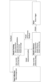
- FIG. 1 is a diagram illustrating an example of a framework for managing AI models.
- FIG. 2 is a diagram showing an example of specifying an AI model.
- FIG. 3 is a diagram showing an example of CSI feedback using an encoder/decoder.
- FIG. 4 illustrates an example life cycle management framework for performance monitoring in a UE according to an embodiment.
- FIG. 5 illustrates an example life cycle management framework for performance monitoring in a BS according to one embodiment.
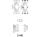
- 6A and 6B are diagrams showing an example of an AI-based beam report.
- FIG. 7 illustrates an example of performance monitoring of CSI compression at the UE side.
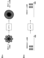
- FIG. 8 is a diagram showing an example of CSI reconstruction using a proxy model.
- FIG. 1 is a diagram illustrating an example of a framework for managing AI models.
- FIG. 2 is a diagram showing an example of specifying an AI model.
- FIG. 3 is a diagram showing an example of CSI feedback using an encoder/decoder.
- FIG. 4 illustrates
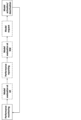
- FIG. 9 is a sequence diagram between a terminal (UE) and a base station (NW) showing an overall view of each embodiment of the present disclosure.
- FIG. 10 is a diagram showing association between RS resources for CSI reporting and RS resources for monitoring reporting.
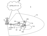
- FIG. 11 is a diagram illustrating an example of a schematic configuration of a wireless communication system according to an embodiment.
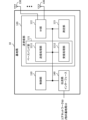
- FIG. 12 is a diagram illustrating an example of the configuration of a base station according to an embodiment.
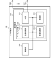
- FIG. 13 is a diagram illustrating an example of the configuration of a user terminal according to an embodiment.
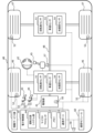
- FIG. 14 is a diagram illustrating an example of the hardware configuration of a base station and a user terminal according to an embodiment.
- FIG. 15 is a diagram illustrating an example of a vehicle according to an embodiment.
- the UE generates (also called determining, calculating, estimating, measuring, etc.) CSI based on a reference signal (RS) (or a resource for the RS) and transmits (also called reporting, feedback, etc.) the generated CSI to a network (e.g., a base station).
- RS reference signal
- the CSI may be transmitted to the base station using, for example, an uplink control channel (e.g., a Physical Uplink Control Channel (PUCCH)) or an uplink shared channel (e.g., a Physical Uplink Shared Channel (PUSCH)).
- PUCCH Physical Uplink Control Channel
- PUSCH Physical Uplink Shared Channel
- CSI includes a Channel Quality Indicator (CQI), a Precoding Matrix Indicator (PMI), a CSI-RS Resource Indicator (CRI), a SS/PBCH Block Resource Indicator (SSBRI), a Layer Indicator (LI), a Rank Indicator (RI), and a Layer 1 Reference Signal Received Power (L1-RSRP).
- CQI Channel Quality Indicator
- PMI Precoding Matrix Indicator
- CRI CSI-RS Resource Indicator
- SSBRI SS/PBCH Block Resource Indicator
- LI Layer Indicator
- RI Rank Indicator
- L1-RSRP Layer 1 Reference Signal Received Power
- L1-Reference Signal Received Power L1-RSRQ
- L1-SINR Signal to Interference plus Noise Ratio
- L1-SNR Signal to Noise Ratio
- information on the channel matrix or channel coefficients
- information on the precoding matrix or precoding coefficients
- information on the beam/Transmission Configuration Indication state TCI state/spatial relation, etc.
- the RS used to generate the CSI may be, for example, at least one of a Channel State Information Reference Signal (CSI-RS), a Synchronization Signal/Physical Broadcast Channel (SS/PBCH) block, a Synchronization Signal (SS), and a DeModulation Reference Signal (DMRS).
- CSI-RS Channel State Information Reference Signal
- SS/PBCH Synchronization Signal/Physical Broadcast Channel
- SS Synchronization Signal
- DMRS DeModulation Reference Signal
- RS Non Zero Power (NZP) CSI-RS, Zero Power (ZP) CSI-RS, CSI Interference Measurement (CSI-IM), CSI-SSB, and SSB
- NZP Non Zero Power
- ZP Zero Power
- CSI-IM CSI Interference Measurement
- CSI-SSB CSI Interference Measurement
- SSB SSB
- CSI-RS may include other reference signals.
- the UE may receive configuration information regarding CSI reporting (which may be referred to as CSI report configuration, report setting, etc.) and control CSI reporting based on the configuration information.
- the report configuration information may be, for example, a Radio Resource Control (RRC) Information Element (IE) "CSI-ReportConfig.”
- RRC Radio Resource Control
- IE Radio Resource Control Information Element
- the CSI reporting configuration may include at least one of the following information: Information regarding the CSI resources used for CSI measurements (resource configuration ID, for example, "CSI-ResourceConfigId”); Information regarding one or more quantities (CSI parameters) of CSI to be reported (report quantity information, e.g., "reportQuantity”); - Report type information (eg, "reportConfigType”) indicating the time domain behavior of the reporting configuration.
- resource configuration ID for example, "CSI-ResourceConfigId”
- Information regarding one or more quantities (CSI parameters) of CSI to be reported report quantity information, e.g., "reportQuantity”
- - Report type information eg, "reportConfigType" indicating the time domain behavior of the reporting configuration.
- a CSI resource may be interchangeably referred to as a time instance, a CSI-RS opportunity/CSI-IM opportunity/SSB opportunity, a CSI-RS resource (one/multiple) opportunity, a CSI opportunity, an opportunity, a CSI-RS resource/CSI-IM resource/SSB resource, a time resource, a frequency resource, an antenna port (e.g., a CSI-RS port), etc.
- the time unit of a CSI resource may be a slot, a symbol, etc.
- the information on the CSI resources may include information on CSI resources for channel measurement, information on CSI resources for interference measurement (NZP-CSI-RS resources), information on CSI-IM resources for interference measurement, etc.
- the reporting amount information may specify any one of the above CSI parameters (e.g., CRI, RI, PMI, CQI, LI, L1-RSRP, etc.) or a combination of these.
- CSI parameters e.g., CRI, RI, PMI, CQI, LI, L1-RSRP, etc.
- the report type information may indicate a periodic CSI (Periodic CSI (P-CSI)) report, an aperiodic CSI (A-CSI) report, or a semi-persistent CSI (Semi-Persistent CSI (SP-CSI)) report.
- P-CSI Period CSI
- A-CSI aperiodic CSI
- SP-CSI semi-persistent CSI
- the UE performs CSI-RS/SSB/CSI-IM measurements based on the CSI resource configuration corresponding to the CSI reporting configuration (the CSI resource configuration associated with CSI-ResourceConfigId) and derives the CSI to be reported based on the measurement results.
- the CSI resource configuration (e.g., the CSI-ResourceConfig information element) may include a csi-RS-ResourceSetList field indicating more specific CSI-RS/SSB resources, resource type information (e.g., "resourceType") indicating the time domain behavior of the resource configuration, etc.
- the resource type information may indicate a P-CSI resource, an A-CSI resource, or an SP-CSI resource.
- AI Artificial Intelligence
- ML machine learning
- CSI channel state information
- UE user equipment
- BS base stations
- CSI channel state information
- UE user equipment
- beam management e.g., improving accuracy, prediction in the time/space domain
- position measurement e.g., improving position estimation/prediction
- the AI model may output at least one piece of information such as an estimate, a prediction, a selected action, a classification, etc. based on the input information.
- the UE/BS may input channel state information, reference signal measurements, etc. to the AI model, and output highly accurate channel state information/measurements/beam selection/position, future channel state information/radio link quality, etc.
- AI may be interpreted as an object (also called a target, object, data, function, program, etc.) having (implementing) at least one of the following characteristics: - Estimation based on observed or collected information; - making choices based on observed or collected information; - Predictions based on observed or collected information.
- estimation, prediction, and inference may be interpreted as interchangeable. Also, in this disclosure, estimate, predict, and infer may be interpreted as interchangeable.
- an object may be, for example, an apparatus such as a UE or a BS, or a device. Also, in the present disclosure, an object may correspond to a program/model/entity that operates in the apparatus.
- an AI model may be interpreted as an object having (implementing) at least one of the following characteristics: - Producing estimates by feeding information, - Predicting estimates by providing information - Discover features by providing information, - Select an action by providing information.
- an AI model may refer to a data-driven algorithm that applies AI techniques to generate a set of outputs based on a set of inputs.
- AI model, model, ML model, predictive analytics, predictive analysis model, tool, autoencoder, encoder, decoder, neural network model, AI algorithm, scheme, etc. may be interchangeable.
- AI model may be derived using at least one of regression analysis (e.g., linear regression analysis, multiple regression analysis, logistic regression analysis), support vector machine, random forest, neural network, deep learning, etc.
- autoencoder may be interchangeably referred to as any autoencoder, such as a stacked autoencoder or a convolutional autoencoder.
- the encoder/decoder of this disclosure may employ models such as Residual Network (ResNet), DenseNet, and RefineNet.
- encoder encoding, encoding/encoded, modification/alteration/control by an encoder, compressing, compress/compressed, generating, generate/generated, etc. may be read as interchangeable terms.
- decoder decoding, decode/decoded, modification/alteration/control by a decoder, decompressing, decompress/decompressed, reconstructing, reconstruct/reconstructed, etc.
- decompressing decompress/decompressed, reconstructing, reconstruct/reconstructed, etc.
- a layer (of an AI model) may be interpreted as a layer (input layer, intermediate layer, etc.) used in an AI model.
- a layer in the present disclosure may correspond to at least one of an input layer, intermediate layer, output layer, batch normalization layer, convolution layer, activation layer, dense layer, normalization layer, pooling layer, attention layer, dropout layer, fully connected layer, etc.
- methods for training an AI model may include supervised learning, unsupervised learning, reinforcement learning, federated learning, and the like.
- Supervised learning may refer to the process of training a model from inputs and corresponding labels.
- Unsupervised learning may refer to the process of training a model without labeled data.
- Reinforcement learning may refer to the process of training a model from inputs (i.e., states) and feedback signals (i.e., rewards) resulting from the model's outputs (i.e., actions) in the environment with which the model interacts.
- terms such as generate, calculate, derive, etc. may be interchangeable.
- terms such as implement, operate, operate, execute, etc. may be interchangeable.
- terms such as train, learn, update, retrain, etc. may be interchangeable.
- terms such as infer, after-training, production use, actual use, etc. may be interchangeable.
- terms such as signal and signal/channel may be interchangeable.
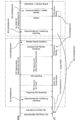
- FIG. 1 shows an example of a framework for managing AI models.
- each stage related to an AI model is shown as a block.
- This example is also referred to as Life Cycle Management (LCM) of an AI model.
- LCM Life Cycle Management
- the data collection stage corresponds to the stage of collecting data for generating/updating an AI model.
- the data collection stage may include data organization (e.g., determining which data to transfer for model training/model inference), data transfer (e.g., transferring data to an entity (e.g., UE, gNB) that performs model training/model inference), etc.
- data collection may refer to a process in which data is collected by a network node, management entity, or UE for the purpose of AI model training/data analysis/inference.
- process and procedure may be interpreted as interchangeable.
- collection may also refer to obtaining a data set (e.g., usable as input/output) for training/inference of an AI model based on measurements (channel measurements, beam measurements, radio link quality measurements, position estimation, etc.).
- offline field data may be data collected from the field (real world) and used for offline training of an AI model.
- online field data may be data collected from the field (real world) and used for online training of an AI model.
- model training is performed based on the data (training data) transferred from the collection stage.
- This stage may include data preparation (e.g., performing data preprocessing, cleaning, formatting, conversion, etc.), model training/validation, model testing (e.g., checking whether the trained model meets performance thresholds), model exchange (e.g., transferring the model for distributed learning), model deployment/update (deploying/updating the model to the entities that will perform model inference), etc.
- AI model training may refer to a process for training an AI model in a data-driven manner and obtaining a trained AI model for inference.
- AI model validation may refer to a sub-process of training to evaluate the quality of an AI model using a dataset different from the dataset used to train the model. This sub-process helps select model parameters that generalize beyond the dataset used to train the model.
- AI model testing may refer to a sub-process of training to evaluate the performance of the final AI model using a dataset different from the dataset used for model training/validation. Note that testing, unlike validation, does not necessarily require subsequent model tuning.
- model inference is performed based on the data (inference data) transferred from the collection stage.
- This stage may include data preparation (e.g., performing data preprocessing, cleaning, formatting, transformation, etc.), model inference, model monitoring (e.g., monitoring the performance of model inference), model performance feedback (feeding back model performance to the entity performing the model training), output (providing model output to the actor), etc.
- AI model inference may refer to the process of using a trained AI model to produce a set of outputs from a set of inputs.
- a UE side model may refer to an AI model whose inference is performed entirely in the UE.
- a network side model may refer to an AI model whose inference is performed entirely in the network (e.g., gNB).
- a one-sided model may refer to a UE-side model or a network-side model.
- a two-sided model may refer to a pair of AI models where joint inference is performed.
- joint inference may include AI inference where the inference is performed jointly across the UE and the network, e.g., a first part of the inference may be performed first by the UE and the remaining part by the gNB (or vice versa).
- AI model monitoring may refer to the process of monitoring the inference performance of an AI model, and may be interpreted interchangeably as model performance monitoring, performance monitoring, etc.
- model registration may refer to making a model executable (registering) through assigning a version identifier to the model and compiling it into the specific hardware used in the inference stage.
- Model deployment may refer to distributing (or activating at) a fully developed and tested run-time image (or an image of the execution environment) of the model to the target (e.g., UE/gNB) where inference will be performed.
- Actor stages may include action triggers (e.g., deciding whether to trigger an action on another entity), feedback (e.g., feeding back information needed for training data/inference data/performance feedback), etc.
- action triggers e.g., deciding whether to trigger an action on another entity
- feedback e.g., feeding back information needed for training data/inference data/performance feedback
- training of a model for mobility optimization may be performed in, for example, Operation, Administration and Maintenance (Management) (OAM) in a network (NW)/gNodeB (gNB).
- OAM Operation, Administration and Maintenance
- NW network
- gNodeB gNodeB
- In the former case interoperability, large capacity storage, operator manageability, and model flexibility (feature engineering, etc.) are advantageous.
- the latency of model updates and the absence of data exchange for model deployment are advantageous.
- Inference of the above model may be performed in, for example, a gNB.
- the entity performing the training/inference may be different.
- the function of the AI model may include beam management, beam prediction, autoencoder (or information compression), CSI feedback, positioning, etc.
- the OAM/gNB may perform model training and the gNB may perform model inference.
- a Location Management Function may perform model training and the LMF may perform model inference.
- the OAM/gNB/UE may perform model training and the gNB/UE may perform model inference (jointly).
- the OAM/gNB/UE may perform model training and the UE may perform model inference.
- model activation may mean activating an AI model for a particular function.
- Model deactivation may mean disabling an AI model for a particular function.
- Model switching may mean deactivating a currently active AI model for a particular function and activating a different AI model.
- Model transfer may also refer to distributing an AI model over the air interface. This may include distributing either or both of the parameters of the model structure already known at the receiving end, or a new model with the parameters. This may also include a complete model or a partial model.
- Model download may refer to model transfer from the network to the UE.
- Model upload may refer to model transfer from the UE to the network.
- Figure 2 shows an example of specifying an AI model.
- the UE and NW e.g., a base station (BS)
- NW e.g., a base station (BS)
- the UE may report, for example, the capabilities of model #1 and model #2 to the NW, and the NW may instruct the UE on the AI model to use.
- AI-based CSI feedback As a use case of utilizing an AI model, CSI compression using a two-sided AI model is being considered. Such a CSI compression method may be called AI-based CSI feedback, and may be realized, for example, by using an autoencoder.
- Figure 3 shows an example of CSI feedback using an encoder/decoder.
- the UE transmits information (CSI feedback information) including encoded bits that are output by inputting CSI to an encoder from an antenna.
- the BS inputs the received CSI feedback information bits to a corresponding decoder to obtain the CSI to be output.
- the input CSI may include, for example, information on channel coefficients (elements of a channel matrix) or information on precoding coefficients (elements of a precoding matrix).
- the CSI may correspond to information on the channel state in the space-frequency domain.
- the input may include information other than CSI.
- the CSI output from the decoder may be reconstructed CSI that corresponds to the input to the encoder, or it may be CSI different from the input to the encoder (e.g., if the input information is information on channel coefficients, it may be information on precoding coefficients, etc.).
- the encoder/decoder may also include pre-processing of the input and post-processing of the output.
- the encoded bits are more compressed than the input information before encoding, which is expected to reduce the communication overhead required for CSI feedback.
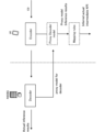
- FIG. 4 illustrates an example of a lifecycle management framework for performance monitoring in a UE according to one embodiment.
- the UE monitors the performance of the model and fallback scheme (non-AI based CSI feedback).
- the UE evaluates the performance of the monitored/reported models and fallback schemes (non-AI based CSI feedback).
- the UE reports the above monitored performance to the NW.
- the NW evaluates the performance of the reported model and fallback scheme.
- the UE sends a request to the NW regarding which model should be applied or whether a fallback scheme should be applied.
- the UE may be instructed which scheme (model) is to be activated.
- the UE may activate a model or a fallback scheme.
- FIG. 5 illustrates an example of a life cycle management framework for performance monitoring in a BS according to one embodiment.
- the UE reports information for performance monitoring in the NW (BS).
- the network monitors the performance of the model and the fallback scheme (non-AI-based CSI feedback).
- the NW evaluates the performance of the model and the fallback scheme.
- the UE may be instructed which scheme (model) is to be activated.
- the UE may activate a model or a fallback scheme.
- AI-based beam report As a use case of utilizing the AI model, spatial domain downlink (DL) beam prediction or temporal DL beam prediction using a one-sided AI model in the UE or NW is being considered.
- DL spatial domain downlink
- BM Beam Management
- FIGS. 6A and 6B are diagrams showing an example of an AI-based beam report.
- FIG. 6A shows spatial domain DL beam prediction.
- the UE may measure a spatially sparse (or thick) beam, input the measurement results, etc., into an AI model, and output a predicted result of the beam quality of a spatially dense (or thin) beam.
- Figure 6B shows temporal DL beam prediction.
- the UE may measure the beam over time, input the measurement results, etc., to an AI model, and output the predicted beam quality of the future beam.
- spatial domain DL beam prediction may be referred to as BM case 1
- temporal DL beam prediction may be referred to as BM case 2.
- temporal DL beam prediction may be referred to as, for example, time domain CSI prediction.
- the beams/RS related to the output (prediction result) of the AI model may be referred to as set A.
- the beams/RS related to the input of the AI model may be referred to as set B.
- Candidates for input to the AI model for BM Case 1/2 include L1-RSRP (Layer 1 Reference Signal Received Power), assistance information (e.g., beam shape information, UE position/direction information, transmit beam usage information), Channel Impulse Response (CIR) information, and corresponding DL transmit/receive beam IDs.
- L1-RSRP Layer 1 Reference Signal Received Power
- assistance information e.g., beam shape information, UE position/direction information, transmit beam usage information
- CIR Channel Impulse Response
- Possible outputs of the AI model for BM Case 1 include the IDs of the top K (K is an integer) transmit/receive beams, the predicted L1-RSRP of these beams, the probability that each beam is in the top K, and the angles of these beams.
- the candidates for the output of the AI model in BM Case 2 include predicted beam failures.
- KPI Key performance indicators
- KPIs for evaluating the performance impact of AI/ML models: ⁇ Performance ⁇ Intermediate KPI, - Link-level and system-level performance, ⁇ Generalization performance, Over-the-air (overhead) - Assistance information overhead, - Data collection overhead, Model delivery/transfer overhead, - Signaling overhead associated with other AI/ML models; Inference complexity, Computational complexity of model inference: floating point operations (FLOPs (note that s is lowercase)) (this means the amount of floating point operations), - Computational complexity of pre- and post-processing, -Model complexity (number of parameters/data size (e.g.
- KPIs are merely examples and other KPIs may be added to the list (e.g. KPIs related to model training, use case specific KPIs that are considered for a given use case, etc.).
- KPIs related to performance may be called performance KPIs.
- a genie-aided beam may refer to a beam with the highest or top K metrics (e.g., values such as L1-RSRP/L1-SINR) among the beams actually measured.
- KPI-1 Difference from the L1-RSRP of the top 1 predicted beam. For example, the difference between the ideal L1-RSRP of the top 1 predicted beam and the ideal L1-RSRP of the top 1 genie-aided beam.
- KPI-2 Prediction accuracy (%) using top 1 and top K beams. This is shown, for example, in the following percentages: Top 1 (%): The percentage of top 1 genie-aided beams that are top 1 beams. Top K/1 (%): The percentage of the top 1 genie-aided beam that is one of the top K predicted beams. Top 1/K (%): The percentage of the top 1 predicted beam that is one of the top K genie-aided beams.
- KPI-3 Cumulative Distribution Function (CDF) of the difference between the top predicted beam and L1-RSRP. For example, the CDF of KPI-1.
- KPI-4 Beam prediction accuracy (%) taking into account the 1 dB margin of the top beam. For example, the percentage of the top genie-aided beams whose ideal L1-RSRP is within 1 dB of the ideal L1-RSRP of the top beam.
- KPI-5 Difference from predicted L1-RSRP. The difference between the L1-RSRP of the top 1/K (%) predicted beam and the ideal L1-RSRP of the same beam.
- L1-RSRP may be replaced with other values included in CSI (e.g., L1-SINR, etc.).
- the beam/RS associated with the output (prediction result) of the AI model may be referred to as set A.
- the beam/RS associated with the input of the AI model may be referred to as set B.
- Set B measurements Measurement of L1-RSRP of set B.
- the overhead is M.
- Predicting Set A Use the trained model to predict the L1-RSRP of Set A based on the measurement data of Set B. This has zero overhead.
- Measurement of Set A Measure the L1-RSRP of Set A as the L1-RSRP of the genie-aided beam. Let this overhead be N.
- Top 1 (and top 1/K(%)) measurement of set A Top 1 (and top 1/K(%)) L1-RSRP measurement of set A.
- the overhead is 1 (1/K).
- Performance monitoring Calculation of existing KPIs. This has zero overhead.
- the overhead when applying KPI-1 to KPI-4 is M+N, and the overhead when applying KPI-5 is M+1 (or 1/K). Therefore, the overhead of KPI-5 ⁇ the overhead of KPI-1 to KPI-4.
- a method of reporting the monitored result (which may be called a monitored result) is considered.
- the UE may be configured to report the monitored result only as shown in at least one of Alt0 to Alt3 below.
- the UE may be configured with a different reporting configuration for monitoring result reporting than for CSI reporting.
- the CSI report and the monitoring result report may be associated with each other.
- at least one of the following settings Alt1 to Alt3 may be applied to the UE.
- Alt1 to Alt3 may be applied, for example, in the case of periodic/semi-persistent reporting, but are not limited thereto, and may also be applied to other cases.
- a number of resource settings may be associated with a CSI reporting configuration.
- two or more resource settings for channel measurements may be associated with a CSI reporting setting.
- one resource setting may correspond to either an RS resource for input (RS resource for input) or an RS resource for reference (RS resource for reference).
- Multiple CSI-RS resource sets may be associated with a CSI reporting setting.
- one CSI-RS resource set may correspond to either RS resources for input (input RS resources) or RS resources for reference (reference RS resources).
- Multiple CSI-RS resources (selected) from one CSI-RS resource set may be associated with a CSI reporting setting.
- one CSI-RS resource set may include RS resources for input (input RS resources) and RS resources for reference (reference RS resources).
- the slot offset between the input RS resource and the reference RS resource may be set/indicated or may be determined based on UE capabilities/predefined rules.
- the UE may trigger a monitoring result report. If a CSI report is associated with the monitoring result report, the UE may be configured with at least one of Alt4 to Alt7 below.
- One CSI-RS resource set (selected) from one resource setting may be associated with each trigger condition.
- one CSI-RS resource set may include RS resources for input (input RS resources) and RS resources for reference (reference RS resources).
- the input RS resource and the reference RS resource may be scheduled in different slots. This allows the input RS resource and the reference RS resource to have different timing offsets (slot offsets).
- the RS triggering offset may be configured for each RS resource or for one RS resource set (eg, including multiple RS resources).
- the slot offset between the input RS resource and the reference RS resource may be configured/indicated or may be determined based on UE capability/predefined rules.
- CSI-RS resource sets (selected from one resource setting) may be associated with each trigger condition.
- one CSI-RS resource set may correspond to either the input RS resources or the reference RS resources. This allows the input RS resources and the reference RS resources to have different timing offsets (slot offsets).
- One or more CSI-RS resource sets may be associated with each trigger condition.
- one resource setting may correspond to either the input RS resource or the reference RS resource. This allows the input RS resource and the reference RS resource to have different timing offsets (slot offsets).
- Different trigger conditions may be set to trigger the RS resources for aperiodic model input (model input RS resources) and the reference RS resources.
- the monitor result report trigger can be associated with any trigger condition.
- the above-mentioned reference resource may be a CSI-RS/DMRS that is beamformed after the CSI report.
- the above-mentioned CSI report and the monitor result report (monitoring report) may be physically separated and logically associated.
- Figure 7 shows an example of performance monitoring of CSI compression at the UE side.
- the UE may monitor the expected performance.
- the performance (expected performance) monitored in FIG. 7 may be at least one of the following: (1) Expected communication quality calculated based on the output of an AI model. For example, expected CQI that satisfies a certain block error probability under a specific resource allocation assumption. (2) The expected performance of the reconstructed CSI compared to the target CSI (e.g., expected noise variance).
- the CQI in (1) may be, for example, at least one of a wideband CQI, an average of subband CQIs, a weighted average of subband CQIs, a maximum/minimum of subband CQI, etc.
- the specific resource allocation may correspond to a frequency/time resource allocation for receiving a certain channel/signal (e.g., PDSCH, PDCCH, corresponding DMRS), and the type of resource allocation may be specified in the standard (e.g., the expected number of symbols, the number of resource blocks, etc.).
- the certain block error probability may be, for example, at least one of 0.1, 0.00001, etc.
- the CSI output from the decoder is the reconstructed CSI that corresponds to the input to the encoder.
- the decoder in the UE is only provided for performance monitoring, and the CSI feedback sent by the UE is the output of the encoder.
- the UE does not have a decoder that corresponds to the encoder.
- the UE performs channel measurements based on the CSI-RS transmitted from the BS and obtains the channel matrix H.
- the UE estimates its performance based on H.
- the UE may perform a specific process on H (e.g., Singular Value Decomposition (SVD)) to obtain W.
- H e.g., Singular Value Decomposition (SVD)
- the UE estimates performance based on W.
- the UE may perform the above-mentioned preprocessing on the above-mentioned W to obtain p-W.
- the UE may estimate performance based on p-W, or may estimate performance based on W.
- the UE may also transmit a performance report to the BS as necessary.
- the UE may receive information on the expected performance of the AI model corresponding to the encoder's AI model from the vendor's data server or NW.
- the information may be included in the AI model information.
- the data server may be interchangeably referred to as a repository, an uploader, a library, a cloud server, or simply a server.
- the data server in this disclosure may be provided by any platform such as GitHub (registered trademark), and may be operated by any company/organization.
- the UE performs channel measurement based on the CSI-RS transmitted from the BS, and obtains the H/W/p-W corresponding to the target CSI.
- the UE also calculates (estimates) the expected performance based on the target CSI and the above-mentioned expected performance information. If performance monitoring is the only task, the UE does not need to operate the encoder.
- the UE can use a proxy model to calculate the expected reconstructed CSI instead of the reconstructed model actually used by the base station.
- the proxy model is a model that mimics the reconstructed model used by the base station.
- the proxy model can be a simple model. This can reduce the processing and storage problems of the UE.
- the proxy model can be different from the actual reconstructed model in the base station. This can avoid the uniqueness problem.
- Figure 8 shows an example of CSI reconstruction (pseudo reconstruction) using a proxy model.
- the UE receives a proxy model for decoding from the NW (base station).
- the UE uses the proxy model to reconstruct the encoded CSI and outputs it as an estimated CSI.
- the UE maps the estimated result to the actual CSI and calculates a KPI (Key Performance Indicator) (e.g., SGCS (squared generalized cosine similarity)).
- KPI Key Performance Indicator
- SGCS squared generalized cosine similarity
- AI/ML-based CSI feedback is important for improving downlink transmission efficiency, and its performance should be monitored in real time.
- the NW/UE can switch models or revert to the existing framework (e.g., UE-side performance monitoring using the proxy model described above) to reduce link outages and throughput loss.
- the existing framework e.g., UE-side performance monitoring using the proxy model described above
- UE-side performance monitoring is one of the candidates for realizing real-time monitoring.
- the UE performs performance monitoring using beamformed CSI-RS (reconfigured and then beamformed CSI-RS).
- the UE also uses DMRS (beamformed DMRS with reported PMI) for performance monitoring to reduce CSI-RS overhead when certain conditions are met (e.g., in the case of SU-MIMO transmission).
- DMRS beamformed DMRS with reported PMI
- the UE has information on the undistorted (more accurate) target CSI, and can quickly identify model performance degradation.
- the proxy model may mean a model that is used only for performance monitoring and has no other uses than performance monitoring.
- the proxy model may mean a model that estimates secondary information (CQI/RI, etc.) of the restored CSI.
- the proxy model needs to be configured as a simple model because it has no other uses than performance monitoring. Therefore, there may be limitations on the complexity of the UE side in terms of implementing the proxy model.
- the inventors have come up with an extended method for improving the accuracy of monitoring on the UE side.
- A/B and “at least one of A and B” may be interpreted as interchangeable. Also, in this disclosure, “A/B/C” may mean “at least one of A, B, and C.”
- Radio Resource Control RRC
- RRC parameters RRC parameters
- RRC messages higher layer parameters, fields, information elements (IEs), settings, etc.
- IEs information elements
- CE Medium Access Control
- update commands activation/deactivation commands, etc.
- the higher layer signaling may be, for example, any one of Radio Resource Control (RRC) signaling, Medium Access Control (MAC) signaling, broadcast information, other messages (e.g., messages from the core network such as positioning protocols (e.g., NR Positioning Protocol A (NRPPa)/LTE Positioning Protocol (LPP)) messages), or a combination of these.
- RRC Radio Resource Control
- MAC Medium Access Control
- LPP LTE Positioning Protocol
- the MAC signaling may use, for example, a MAC Control Element (MAC CE), a MAC Protocol Data Unit (PDU), etc.
- the broadcast information may be, for example, a Master Information Block (MIB), a System Information Block (SIB), Remaining Minimum System Information (RMSI), Other System Information (OSI), etc.
- MIB Master Information Block
- SIB System Information Block
- RMSI Remaining Minimum System Information
- OSI System Information
- the physical layer signaling may be, for example, Downlink Control Information (DCI), Uplink Control Information (UCI), etc.
- DCI Downlink Control Information
- UCI Uplink Control Information
- index identifier
- indicator indicator
- resource ID etc.
- sequence list, set, group, cluster, subset, etc.
- TRP
- CSI-RS Non-Zero Power (NZP) CSI-RS, Zero Power (ZP) CSI-RS, and CSI Interference Measurement (CSI-IM) may be interchangeable.
- CSI-RS may include other reference signals.
- the measured/reported RS may refer to the RS measured/reported for CSI reporting.
- timing, time, duration, slot, subslot, symbol, subframe, etc. may be interpreted as interchangeable.
- direction, axis, dimension, domain, polarization, polarization component, etc. may be interpreted as interchangeable.
- estimation, prediction, and inference may be interpreted as interchangeable. Also, in this disclosure, estimate, predict, and infer may be interpreted as interchangeable.
- the autoencoder, encoder, decoder, etc. may be interpreted as at least one of a model, an ML model, a neural network model, an AI model, an AI algorithm, etc.
- the autoencoder may be interpreted as any autoencoder, such as a stacked autoencoder or a convolutional autoencoder.
- the encoder/decoder of the present disclosure may employ models such as Residual Network (ResNet), DenseNet, and RefineNet.
- bits, bit strings, bit series, series, values, information, values obtained from bits, information obtained from bits, etc. may be interpreted as interchangeable.
- a layer for an encoder
- a layer may be interchangeably read as a layer (input layer, intermediate layer, etc.) used in an AI model.
- a layer in the present disclosure may correspond to at least one of an input layer, intermediate layer, output layer, batch normalization layer, convolution layer, activation layer, dense layer, normalization layer, pooling layer, attention layer, dropout layer, fully connected layer, etc.
- RSRP may be interchangeably read as any parameter related to reception power/reception quality, etc. (e.g., RSRQ, SINR, CSI, etc.).
- the RS may be, for example, a CSI-RS, an SS/PBCH block (SS block (SSB)), etc.
- the RS index may be a CSI-RS resource indicator (CSI-RS Resource Indicator (CRI)), an SS/PBCH block resource indicator (SS/PBCH Block Indicator (SSBRI)), etc.
- CSI-RS Resource Indicator CRI
- SSBRI SS/PBCH Block Indicator
- channel measurement/estimation may be performed using at least one of, for example, a Channel State Information Reference Signal (CSI-RS), a Synchronization Signal (SS), a Synchronization Signal/Physical Broadcast Channel (SS/PBCH) block, a DeModulation Reference Signal (DMRS), a Sounding Reference Signal (SRS), etc.
- CSI-RS Channel State Information Reference Signal
- SS Synchronization Signal
- SS/PBCH Synchronization Signal/Physical Broadcast Channel
- DMRS DeModulation Reference Signal
- SRS Sounding Reference Signal
- the terms receive beam assumption, number of receive beams, receive beam index, receive beam selection, receive beam setting, and receive beam instruction may be interchangeable.
- the terms receive beam, transmit beam, DL receive beam, DL transmit beam, and transmit and receive beam pairs may be interchangeable.
- transmit/receive beam may be interchangeable with transmit/receive beams for beam prediction, and transmit/receive beams for CSI measurement/reporting for beam prediction.
- functionality may refer to the use of a model or the physical meaning of the model's input/output. Multiple models may have the same functionality. Monitoring (checking performance)/activation/deactivation/switching/fallback/update may be instructed (controlled) based on the functionality (e.g., for each function).
- a model ID may also refer to an identifier for a model (or a set of models). Multiple models may be assigned the same model ID in an actual deployment. In this case, these models may actually be different models (e.g., have different number of layers, etc.), but may be treated as the same model.
- the use cases may include AI/ML for at least one of enhanced CSI feedback/beam management/enhanced positioning.
- the use cases may also include other new use cases for AI/ML.
- the model ID may be interchangeably read as a meta information (or a set of meta information) ID.
- the meta information (or meta information ID) may be associated with information regarding the applicability of the model/functionality, the environment, the UE/gNB settings, etc.
- functionality, function, functionality ID, model, and model ID may be interpreted interchangeably.
- update, report, and send may be read interchangeably.
- meta information may be interpreted as interchangeable.
- monitor and evaluation may be interpreted interchangeably.
- entity specific entity, UE, NW, gNB, and LMF may be read as interchangeable.
- NW may be interpreted as interchangeable.
- the UE side model and UE may be interpreted as interchangeable.
- model UE side model
- logical model logical model
- physical model may be interchangeable.
- model/functionality may refer to a data-driven algorithm that applies AI/ML techniques to generate a set of outputs based on a set of inputs.
- performance indicators and monitoring indicators may be interpreted as interchangeable.
- association, correspondence, and mapping may be interpreted as interchangeable.
- monitor result monitored result
- post-monitoring result post-monitoring result
- monitoring result may be read interchangeably.
- the monitoring results may include information regarding at least one of the inference results, a performance index, and the content of an event occurrence based on the performance index/whether or not an event has occurred.
- the UE may report the following information as monitoring results: Performance metrics corresponding to the monitored model/functionality.
- Performance metrics corresponding to the monitored model/functionality.
- An event occurs in the calculation of a performance index corresponding to a monitored model/functionality (eg, the value of a positive index is greater/less than a threshold for a certain duration).
- AI/ML-based CSI reporting may refer to a CSI report associated with a model ID or specific functionality, where the specific functionality may be, for example, at least one of predicted CSI, compressed CSI, advanced CSI, and type [x] CSI.
- AI/ML-based CSI reporting and CSI reporting may be read interchangeably.
- a proxy model may refer to a model that is used only for performance monitoring and has no other uses other than performance monitoring.
- a proxy model may refer to a model that estimates secondary information (CQI/RI, etc.) of the restored CSI.
- AI/ML functionality, AI/ML CSI functionality may refer to functionality commanded by the NW or reported by the UE, such as at least one of predicted CSI, compressed CSI, advanced CSI, and type [x] CSI.
- AI/ML functionality, AI/ML CSI functionality, and functionality may be read interchangeably.
- an AI/ML model an AI/ML CSI model may refer to a model/entity that is identified by a specific ID and performs a specific function (functionality).
- report quantity information regarding report quantity, and report quantity information may be read interchangeably.
- reporting settings may be read interchangeably.
- report CSI report, measurement result report, monitoring report, and monitor result report may be read interchangeably.
- CSI-RS and PDSCH/DMRS may be interpreted as interchangeable.
- type X monitoring may refer to monitoring (results) based on precoded RS resources.
- type Y monitoring may refer to monitoring (results) based on PDSCH/DMRS.
- RS Type B may refer to an RS (signal/channel) associated with a measurement report/monitoring result report
- RS Type A may refer to an RS (signal/channel) associated with a CSI report associated with a model ID or specific functionality/feature.
- performance metrics metrics for monitoring reports, and KPIs may be interpreted interchangeably.
- the embodiments of the present disclosure can be broadly classified as follows.
- First embodiment Reporting configuration for CSI-RS based monitoring.
- Second embodiment Triggering of CSI-RS transmission and monitoring reports.
- Third embodiment Relationship between CSI reports and monitoring reports.
- Fourth embodiment Reporting configuration for PDSCH/DMRS based monitoring.
- Fifth embodiment Triggering of aperiodic CSI-RS transmission and monitoring reports.
- Sixth embodiment Relationship between CSI reports and monitoring reports.
- Seventh embodiment UE behavior in performance monitoring based on new performance indicators (KPIs).
- Eighth embodiment UE behavior regarding monitoring of layer mapping with rank adaptation. Each embodiment will be described below based on these.
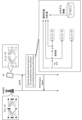
- FIG. 9 is a sequence diagram between a terminal (UE) and a base station (NW) showing an overall picture of each embodiment of the present disclosure.
- the procedure shown in FIG. 9 is merely an example, and the order of each step can be changed as appropriate as long as no contradiction occurs.
- first the network sends reporting settings for CSI reporting to the UE.
- the network sends activation of CSI feedback (CSF) to the UE.
- CSF CSI feedback
- the NW transmits a reporting configuration for monitoring reports to the UE (first embodiment).
- the reporting configuration for CSI reports and the reporting configuration for monitoring reports are associated with each other (third embodiment).
- the network sends a CSI report trigger (trigger instruction) to the UE.
- the network transmits input RS resources (RS type A) to the UE.
- the UE performs CSI compression based on the input RS resources.
- the UE performs (sends) a CSI report to the network.
- the network performs CSI registration and beamforming of the CSI-RS.
- the network transmits reference RS resources (RS type B) to the UE.
- RS type B reference RS resources
- the UE performs performance monitoring.
- the network performs scheduling for CSI monitoring feedback.
- the UE transmits a monitoring result report (monitoring report) to the NW (second embodiment). In other words, the UE feeds back the monitoring result to the NW.
- the NW transmits a reporting configuration for monitoring reports to the UE (fourth embodiment).
- the reporting configuration for CSI reports and the reporting configuration for monitoring reports are associated with each other (sixth embodiment).
- the network performs SU-MIMO beamforming on the reconstructed CSI.
- the network transmits PDSCH/DMRS to the UE.
- the network schedules (triggers) monitoring reports for PDSCH/DMRS (fifth embodiment).
- the UE sends ACK/NACK and monitoring results (monitoring report) to the NW.
- each embodiment/option may be applied alone or in combination with multiple options.
- the first embodiment relates to monitoring based on the CSI framework, and in particular describes report configuration.
- the CSI-RS may be a precoded/beamformed CSI-RS.
- the UE may be configured in the CSI-RS to monitor the performance of AI/ML-based CSI reporting (i.e., CSI reporting performance monitoring) by at least one of the following options.
- the configuration regarding CSI reporting performance monitoring may be referred to as monitor reporting configuration.
- Option 1-1 relates to a configuration based on the CSI framework.
- the UE may be configured for performance monitoring of CSI reports by the CSI report configuration (CSI-ReportConfig) received from the NW via higher layer signaling/physical layer signaling.
- CSI-ReportConfig the CSI report configuration
- the CSI reporting configuration may include at least type X monitoring results within information (report quantity information, e.g., "reportQuantity" in the RRC IE) regarding one or more quantities of CSI to be reported (one or more CSI parameters).
- report quantity information e.g., "reportQuantity" in the RRC IE
- the type X monitoring result may refer to a monitoring result based on precoded RS resources.
- the reporting amount for type X monitoring results may be a gap (measurement gap) of RSRP/SINR/CQI.
- the reporting amount is a gap of RSRP
- the UE may be configured with only CSI resources for channel measurement, not including resources for interference measurement, in the CSI reporting configuration.
- Options 1-2 relate to configurations based on frameworks other than the CSI framework (e.g., the LCM framework in Rel. 19 and later).
- the UE may be configured to monitor the performance of CSI reports by specific signaling received from the network via higher layer signaling/physical layer signaling.
- the specified signaling may include a CSI resource set index or a CSI resource index for the monitoring result of type X.
- the specified signaling may be dedicated signaling or signaling for purposes other than CSI reporting (e.g., signaling for model/functionality activation, signaling for model switching, etc.).
- the resources for monitoring need to be different from the resources for CSI compression and CSI feedback.
- the resources for CSI compression and CSI feedback may be configured by separate signaling corresponding to CSI reporting.
- the UE may expect the above signaling to include an indication of the model/functionality and an index to the model/functionality (Model ID/Functionality ID).
- the UE may also expect the above signaling to include monitor reporting configuration, which may include instructions regarding the periodicity and resources for monitor reporting.
- the UE may treat the RS resources configured in Options 1-1 to 1-2 above as RS type B.
- the UE may expect the configured CSI reporting to be periodic/semi-persistent/aperiodic.
- RS Type B may refer to an RS (signal/channel) associated with a measurement report/monitor result report.
- the UE can properly recognize the reporting settings for monitoring based on CSI-RS.
- the second embodiment relates to monitoring based on the CSI framework, in particular the triggering of CSI-RS transmission and monitoring reports.
- the UE may be triggered to perform monitoring reporting based on the existing CSI framework, i.e., RRC (e.g., CSI-AperiodicTriggerStatelist)/MAC CE/DCI or RRC (e.g., CSI-SemiPersistentOnPUSCH-TriggerStatelist)/DCI may be used to trigger monitoring reporting.
- RRC e.g., CSI-AperiodicTriggerStatelist
- MAC CE/DCI e.g., CSI-SemiPersistentOnPUSCH-TriggerStatelist
- DCI CSI-SemiPersistentOnPUSCH-TriggerStatelist
- the UE may be triggered to report type X monitoring results by higher layer signaling/physical layer signaling.
- the UE may also expect the RS resource ID/report ID to be configured/indicated by higher layer/physical layer signaling.
- the RS resource ID/report ID may correspond to the ID configured for type X monitoring.
- Performance monitoring allows for fewer trigger states required for reporting, since individual signaling (e.g., dedicated signaling, such as a new DCI) requires less overhead than CSI framework signaling.
- the UE may be configured with a new parameter (monitoring-TriggerStatelist) consisting of N (N ⁇ 16) trigger states, where each trigger state in the monitoring-TriggerStatelist may include M resource IDs/report IDs.
- monitoring-TriggerStatelist consisting of N (N ⁇ 16) trigger states, where each trigger state in the monitoring-TriggerStatelist may include M resource IDs/report IDs.
- the UE may decide whether to use existing parameters (CSI-AperiodicTriggerStatelist/CSI-SemiPersistentOnPUSCH-TriggerStatelist) or other (new) parameters (monitoring-TriggerStatelist) based on the detected triggering DCI (triggering DCI).
- existing parameters CSI-AperiodicTriggerStatelist/CSI-SemiPersistentOnPUSCH-TriggerStatelist
- new parameters monitoring-TriggerStatelist
- the UE may use a new parameter (monitoring-TriggerStatelist).
- the triggering DCI may add a new field, for example, 1 bit, to an existing DCI, and use the new field to indicate whether the DCI is for a CSI report or a monitoring report.
- the UE may use the existing parameters (CSI-AperiodicTriggerStatelist/CSI-SemiPersistentOnPUSCH-TriggerStatelist).
- the UE can appropriately control the triggering of monitoring reports based on the CSI-RS.
- the third embodiment relates to monitoring based on a CSI framework, and in particular describes a relationship (association) between an RS resource for a CSI report and an RS resource for a monitoring report.
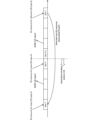
- Figure 10 is a diagram showing an association between an RS resource for a CSI report and an RS resource for a monitoring report.
- RS type B a signal/channel of RS type B (hereinafter simply referred to as RS type B) in a certain time slot (hereinafter simply referred to as slot) T.
- the RS resource of RS type B may be read as the reference RS resource and vice versa.
- the UE associates the RS type B with the RS type A signal/channel (hereinafter simply referred to as RS type A) received in slot T'.
- the UE then derives the monitoring result using the pair (which may be referred to as an RS pair) of the two associated signals/channels (RS type A and RS type B).
- slot T' may be a slot a predetermined period before slot T (a predetermined slot: 9 slots in FIG. 10).
- RS type A may mean an RS (signal/channel) related to a CSI report associated with a model ID or a specific functionality/characteristic.
- the CSI report may be, for example, a CSI report for predicted CSI or compressed CSI.
- the RS resource of RS type A may be read as an input RS resource.
- the UE may determine the above-mentioned slot T' according to at least one of Alt3-1 to Alt3-2 below. That is, slot T' may be any of the slots shown in Alt3-1 to Alt3-2 below.
- ⁇ Alt3-1> The slot in which RS Type A is transmitted and is used for the latest AI/ML-based CSI reporting.
- the slot is a slot in which RS type A is transmitted before the slot T-k and is used for the latest AI/ML-based CSI report (slot T′′ in FIG. 10).
- k may be set/indicated in higher layer signaling/physical layer signaling, or may be predefined by a specification.
- the UE may associate RS type B with RS type A and ignore the input RS resources used by other models, where the other models may be models (different from AI/ML CSI functionality/models) that are not associated with RS type A.
- the UE can appropriately distinguish between CSI reports and monitoring reports based on the type of RS resource.
- the fourth embodiment relates to monitoring based on PDSCH/DMRS, and in particular describes report configuration.
- the UE may be configured to monitor the performance of AI/ML-based CSI reporting (i.e., CSI reporting performance monitoring) in PDSCH/DMRS resources scheduled as RS type B by at least one of the following options:
- the UE may be configured for CSI reporting performance monitoring by the CSI report configuration (CSI-ReportConfig) received from the NW via higher layer signaling/physical layer signaling.
- the higher layer signaling/physical layer signaling may configure/indicate the measurement resources of the PDSCH/DMRS scheduled for the UE.
- the CSI reporting configuration may include at least type X/Y monitoring results within information (report quantity information, e.g., "reportQuantity" in the RRC IE) regarding one or more quantities of CSI to be reported (one or more CSI parameters).
- report quantity information e.g., "reportQuantity" in the RRC IE
- the type Y monitoring result may mean a monitoring result based on PDSCH/DMRS. Also, the type Y monitoring may be the same as the type X monitoring.
- the reporting amount for type X/Y monitoring results may be the RSRP/SINR/CQI gap (measurement gap).
- the UE may be configured to monitor the performance of CSI reports by specific signaling received from the network via higher layer signaling/physical layer signaling.
- the specified signaling may include settings/instructions for monitoring PDSCH/DMRS.
- the specified signaling may be dedicated signaling or signaling for purposes other than CSI reporting (e.g., signaling for LCM of AI/ML-based CSI reporting, signaling for model/functionality activation for AI/ML-based CSI reporting, signaling for model switching, etc.).
- the UE may expect the above signaling to include an indication of the model/functionality and an index to the model/functionality (Model ID/Functionality ID).
- the UE may also expect the above signaling to include monitor reporting configuration, which may include instructions regarding the periodicity and resources for monitor reporting.
- monitoring of PDSCH/DMRS may be opportunistic based on scheduling and conditions (e.g., SU-MIMO transmission, latency).
- the gNB itself may determine whether PDSCH/DMRS is a suitable opportunity for monitoring and notify the UE.
- the report type may be periodic/semi-persistent/non-periodic, and the following may be exemplified:
- the corresponding PDSCH/DMRS may be set by the index of the semi-persistent scheduling (SPS) PDSCH.
- SPS semi-persistent scheduling
- the corresponding PDSCH/DMRS may be determined based on the time offset between the PDSCH/DMRS and the PUCCH/PUSCH for reporting.
- the time offset may be indicated by DCI triggering in case of semi-persistent reporting, or set by RRC in case of periodic/aperiodic reporting.
- the corresponding PDSCH/DMRS may be determined as (based on) the latest PDSCH reception at least X symbols/slots prior to the reporting PUCCH/PUSCH.
- the corresponding PDSCH/DMRS may be determined as (based on) the configured/indicated antenna port.
- the PDSCH/DMRS scheduled at antenna port 1000 may be utilized.
- the corresponding PDSCH/DMRS may be determined as (based on) the configured/indicated HARQ process number.
- the UE can properly recognize the monitoring report settings based on the PDSCH/DMRS.
- the fifth embodiment relates to triggering of monitoring reports based on PDSCH/DMRS.
- the UE may be triggered to report type Y monitoring results by higher layer signaling/physical layer signaling.
- the UE may report type Y monitoring results using higher layer signaling/physical layer signaling when at least one of the following conditions 5-1 to 5-4 is satisfied.
- Reporting of type Y monitoring results is configured/indicated by higher layer/physical layer signaling, which may be the same as the signaling that schedules the PDSCH or may be different signaling.
- Condition 5-1 AND Condition 5-2 In this case, the condition is satisfied only when both conditions 5-1 and 5-2 are satisfied.
- condition 5-1 has a higher priority than condition 5-3.
- condition 5-1 with the higher priority is given priority. In other words, whether the condition is met or not may depend on the outcome of the condition 5-1.
- the UE can appropriately control the triggering of monitoring reports based on PDSCH/DMRS.
- the sixth embodiment relates to monitoring based on PDSCH/DMRS, and in particular describes the relationship (association) between RS resources for CSI reporting and RS resources for monitoring reporting. Note that the sixth embodiment can be applied by replacing the CSI-RS in the third embodiment with PDSCH/DMRS. That is, the contents of FIG. 10 can also be applied to the following description.
- a UE when a UE receives RS type B in a certain time slot T, the UE associates RS type B with RS type A received in slot T'. Then, the UE derives the monitoring result using a pair (which may be called an RS pair) of the two associated signals/channels (RS type A and RS type B).
- a pair which may be called an RS pair
- slot T' may be a slot a predetermined period before slot T (a predetermined slot: 9 slots in FIG. 10).
- RS type A may refer to an RS (signal/channel) related to a CSI report associated with a model ID or a specific functionality/characteristic.
- the CSI report may be, for example, a CSI report for predicted CSI or compressed CSI.
- the UE may determine the above-mentioned slot T' according to at least one of Alt6-1 to Alt6-2 below. That is, slot T' may be any of the slots shown in Alt6-1 to Alt6-2 below.
- ⁇ Alt6-1> The slot in which RS Type A is transmitted and is used for the latest AI/ML-based CSI reporting.
- the slot is a slot in which RS type A is transmitted before the slot T-k and is used for the latest AI/ML-based CSI report (slot T′′ in FIG. 10).
- k may be set/indicated in higher layer signaling/physical layer signaling, or may be predefined by a specification.
- the UE may associate RS type B with RS type A and ignore the input RS resources used by other models, where the other models may be models (different from AI/ML CSI functionality/models) that are not associated with RS type A.
- the seventh embodiment relates to UE operation in performance monitoring based on a new performance indicator.
- Aspect 7-1 relates to a new performance index.
- the UE may be configured/instructed by higher layer signaling/physical layer signaling of the performance indicators for performance monitoring and the corresponding values.
- the UE may have the performance indicators for performance monitoring and the corresponding values determined by the specifications.
- the performance indicators and the corresponding values may be at least one of the following options 7-1 to 7-3.
- Absolute value of measured RSRP/SINR/CQI Absolute value for measured value:. This absolute value may be referred to as an absolute threshold metric value.
- Target RSRP/SINR/CQI Relative offset value (difference between target and measured values) expressed in measured RSRP/SINR/CQI.
- the difference value may be called a relative offset metric value.
- the target values (target RSRP/SINR/CQI) may be derived based on configured/indicated parameters or predefined rules.
- Aspect 7-2 relates to UE operation of performance monitoring based on a novel performance indicator.
- the UE may monitor the performance of the AI/ML-based CSI report based on a pair of two signals/channels (RS type A and RS type B) associated with each other (may be called an RS pair). The procedure is described below.
- the UE calculates target values (target RSRP/SINR/CQI) based on RS type A.
- ⁇ Step 2> The UE measures the measurements (measured RSRP/SINR/CQI) based on RS type B.
- the UE may derive the monitoring result based on the above performance indicators and their corresponding values (eg, RS pairs).
- the UE can appropriately control monitoring reports based on the new performance indicators.
- An eighth embodiment describes UE operation with respect to monitoring layer mapping with rank adaptation.
- the UE may perform the following operations:
- the UE may monitor the layer (number) corresponding to the smallest value (number) of the port/layer number and rank indicator.
- the UE may assume that the port/layer order is the same between the precoding matrix indicator (PMI) in the AI/ML-based CSI report and RS type B.
- the UE may be configured/instructed on the port/layer order by higher layer/physical layer signaling, which may include a bit indicating the layer mapping.
- the UE can appropriately control the UE operation related to monitoring the layer (mapping) based on the rank indicator.
- AI model information may mean information including at least one of the following: ⁇ Information on input/output of AI model. - Pre-processing/post-processing information for input/output of AI models. ⁇ Information on AI model parameters. - Training information for AI models. -Inference information for AI models. ⁇ Performance information about the AI model.
- the input/output information of the AI model may include information regarding at least one of the following: Input/output data content (e.g. RSRP, SINR, amplitude/phase information in the channel matrix (or precoding matrix), information on the Angle of Arrival (AoA), information on the Angle of Departure (AoD), location information).
- Input/output data content e.g. RSRP, SINR, amplitude/phase information in the channel matrix (or precoding matrix), information on the Angle of Arrival (AoA), information on the Angle of Departure (AoD), location information).
- Supporting information for the data may be called meta-information).
- the type of input/output data e.g. immutable values, floating point numbers).
- the bit width of the input/output data eg, 64 bits for each input value).
- Quantization interval (quantization step size) of input/output data eg, 1 dBm for L1-RSRP).
- the information regarding AoA may include information regarding at least one of the azimuth angle of arrival and the zenith angle of arrival (ZoA). Furthermore, the information regarding AoD may include information regarding at least one of the azimuth angle of departure and the zenith angle of departure (ZoD), for example.
- the location information may be location information regarding the UE/NW.
- the location information may include at least one of information (e.g., latitude, longitude, altitude) obtained using a positioning system (e.g., a satellite positioning system (Global Navigation Satellite System (GNSS), Global Positioning System (GPS), etc.)), information on the BS adjacent to (or serving) the UE (e.g., a BS/cell identifier (ID), a BS-UE distance, a direction/angle of the BS (UE) as seen from the UE (BS), coordinates of the BS (UE) as seen from the UE (BS) (e.g., coordinates on the X/Y/Z axes), etc.), a specific address of the UE (e.g., an Internet Protocol (IP) address), etc.
- IP Internet Protocol
- the location information of the UE is not limited to information based on the position of the BS, and may be information based on a specific point.
- the location information may include information about its implementation (e.g., location/position/orientation of antennas, location/orientation of antenna panels, number of antennas, number of antenna panels, etc.).
- the location information may include mobility information.
- the mobility information may include information indicating at least one of the following: information indicating a mobility type, a moving speed of the UE, an acceleration of the UE, a moving direction of the UE, etc.
- the mobility type may correspond to at least one of fixed location UE, movable/moving UE, no mobility UE, low mobility UE, middle mobility UE, high mobility UE, cell-edge UE, not-cell-edge UE, etc.
- environmental information may be information regarding the environment in which the data is acquired/used, and may correspond to, for example, frequency information (such as a band ID), environmental type information (information indicating at least one of indoor, outdoor, Urban Macro (UMa), Urban Micro (Umi), etc.), information indicating Line Of Site (LOS)/Non-Line Of Site (NLOS), etc.
- frequency information such as a band ID
- environmental type information information indicating at least one of indoor, outdoor, Urban Macro (UMa), Urban Micro (Umi), etc.
- LOS Line Of Site
- NLOS Non-Line Of Site
- LOS may mean that the UE and BS are in an environment where they can see each other (or there is no obstruction)
- NLOS may mean that the UE and BS are not in an environment where they can see each other (or there is an obstruction).
- Information indicating LOS/NLOS may indicate a soft value (e.g., the probability of LOS/NLOS) or a hard value (e.g., either LOS or NLOS).
- meta-information may mean, for example, information regarding input/output information suitable for an AI model, information regarding data that has been acquired/can be acquired, etc.
- meta-information may include information regarding beams of RS (e.g., CSI-RS/SRS/SSB, etc.) (e.g., the pointing angle of each beam, 3 dB beam width, the shape of the pointed beam, the number of beams), gNB/UE antenna layout information, frequency information, environmental information, meta-information ID, etc.
- RS e.g., CSI-RS/SRS/SSB, etc.
- gNB/UE antenna layout information e.g., the pointing angle of each beam, 3 dB beam width, the shape of the pointed beam, the number of beams
- meta-information may be used as input/output of an AI model.
- the pre-processing/post-processing information for the input/output of the AI model may include information regarding at least one of the following: Whether to apply normalization (e.g., Z-score normalization, min-max normalization). Parameters for normalization (eg, mean/variance for Z-score normalization, min/max for min-max normalization). Whether to apply a specific numeric transformation method (e.g., one hot encoding, label encoding, etc.). Selection rule for whether or not to use as training data.
- normalization e.g., Z-score normalization, min-max normalization
- Parameters for normalization eg, mean/variance for Z-score normalization, min/max for min-max normalization
- a specific numeric transformation method e.g., one hot encoding, label encoding, etc.
- the information of the parameters of the AI model may include information regarding at least one of the following: - Weight information (e.g., neuron coefficients (connection coefficients)) in an AI model. ⁇ Structure of the AI model. - The type of AI model as a model component (e.g., Residual Network (ResNet), DenseNet, RefineNet, Transformer model, CRBlock, Recurrent Neural Network (RNN), Long Short-Term Memory (LSTM), Gated Recurrent Unit (GRU)). - Functions of the AI model as model components (e.g., decoder, encoder).
- ResNet Residual Network
- DenseNet DenseNet
- RefineNet Transformer model
- CRBlock Recurrent Neural Network
- RNN Recurrent Neural Network
- LSTM Long Short-Term Memory
- GRU Gated Recurrent Unit
- the weight information in the AI model may include information regarding at least one of the following: - Bit width (size) of the weight information. Quantization interval of weight information. - Granularity of weight information. - The range of possible weight information. ⁇ Weight parameters in AI models. - Information on the difference from the AI model before the update (if updating). - Method of weight initialization (e.g., zero initialization, random initialization (based on normal/uniform/truncated normal distribution), Xavier initialization (for sigmoid function), He initialization (for Rectified Linear Units (ReLU))).
- the structure of the AI model may also include information regarding at least one of the following: ⁇ Number of layers. - The type of layer (e.g., convolutional, activation, dense, normalization, pooling, attention). ⁇ Layer information. Time series specific parameters (e.g. bidirectionality, time step). Parameters for training (e.g., type of feature (L2 regularization, dropout feature, etc.), where to put this feature (e.g., after which layer)).
- ⁇ Number of layers e.g., convolutional, activation, dense, normalization, pooling, attention.
- ⁇ Layer information Time series specific parameters (e.g. bidirectionality, time step).
- Parameters for training e.g., type of feature (L2 regularization, dropout feature, etc.), where to put this feature (e.g., after which layer)).
- the layer information may include information regarding at least one of the following: - The number of neurons in each layer. ⁇ Kernel size. - Stride for pooling/convolutional layers. -Pooling method (MaxPooling, AveragePooling, etc.). ⁇ Residual block information. ⁇ Number of heads. - Normalization method (batch normalization, instance normalization, layer normalization, etc.). Activation functions (sigmoid, tanh function, ReLU, leaky ReLU information, Maxout, Softmax).
- An AI model may be included as a component of another AI model.
- an AI model may be an AI model in which processing proceeds in the order of model component #1 (ResNet), model component #2 (a transformer model), a dense layer, and a normalization layer.
- ResNet model component #1
- model component #2 a transformer model
- dense layer a dense layer
- normalization layer a normalization layer
- Training information for the AI model may include information regarding at least one of the following: Information for the optimization algorithm (e.g. type of optimization (Stochastic Gradient Descent (SGD)), AdaGrad, Adam, etc.), parameters of the optimization (learning rate, momentum information, etc.). Loss function information (e.g., information on the metrics of the loss function (Mean Absolute Error (MAE)), Mean Square Error (MSE)), Cross Entropy Loss, NLL Loss, Kullback-Leibler (KL) Divergence, etc.)).
- - Parameters to be frozen for training e.g. layers, weights
- - Parameters to be updated e.g. layers, weights
- Parameters e.g. layers, weights
- Parameters that should be (are used as) initial parameters for training. How to train/update the AI model (e.g., (recommended) number of epochs, batch size, number of data used for training).
- the inference information for the AI model may include information regarding decision tree branch pruning, parameter quantization, and the function of the AI model.
- the function of the AI model may correspond to at least one of, for example, time domain beam prediction, spatial domain beam prediction, autoencoder for CSI feedback, and autoencoder for beam management.
- An autoencoder for CSI feedback may be used as follows: - The UE inputs the CSI/channel matrix/precoding matrix into the AI model of the encoder and transmits the encoded bits output as CSI feedback (CSI report). - The BS reconstructs the CSI/channel matrix/precoding matrix, which is output as input to the AI model of the decoder using the received encoded bits.
- the UE/BS may input measurement results (beam quality, e.g., RSRP) based on sparse (or thick) beams into an AI model to output dense (or thin) beam quality.
- beam quality e.g., RSRP
- the UE/BS may input time series (past, present, etc.) measurement results (beam quality, e.g., RSRP) into an AI model and output future beam quality.
- time series past, present, etc.
- beam quality e.g., RSRP
- the performance information regarding the AI model may include information regarding the expected value of a loss function defined for the AI model.
- the AI model information in this disclosure may include information regarding the scope of application (scope of applicability) of the AI model.
- the scope of application may be indicated by a physical cell ID, a serving cell index, etc.
- Information regarding the scope of application may be included in the above-mentioned environmental information.
- AI model information regarding a specific AI model may be predetermined in a standard, or may be notified to the UE from the network (NW).
- An AI model defined in a standard may be referred to as a reference AI model.
- AI model information regarding a reference AI model may be referred to as reference AI model information.
- the AI model information in the present disclosure may include an index for identifying the AI model (e.g., may be called an AI model index, an AI model ID, a model ID, etc.).
- the AI model information in the present disclosure may include an AI model index in addition to/instead of the input/output information of the AI model described above.
- the association between the AI model index and the AI model information (e.g., input/output information of the AI model) may be predetermined in a standard, or may be notified to the UE from the NW.
- the AI model information in this disclosure may be associated with an AI model and may be referred to as AI model relevant information, simply relevant information, etc.
- the AI model relevant information does not need to explicitly include information for identifying the AI model.
- the AI model relevant information may be information that includes only meta information, for example.
- the model ID may be interchangeably read as an ID (model set ID) corresponding to a set of AI models.
- the model ID may be interchangeably read as a meta information ID.
- the meta information (or meta information ID) may be associated with information regarding the beam (beam setting) as described above.
- the meta information (or meta information ID) may be used by the UE to select an AI model taking into account which beam the BS is using, or may be used to notify the BS of which beam to use to apply the AI model deployed by the UE.
- the meta information ID may be interchangeably read as an ID (meta information set ID) corresponding to a set of meta information.
- any information may be notified to the UE (from the NW) (in other words, any information received from the BS in the UE) using physical layer signaling (e.g., DCI), higher layer signaling (e.g., RRC signaling, MAC CE), a specific signal/channel (e.g., PDCCH, PDSCH, reference signal), or a combination thereof.
- physical layer signaling e.g., DCI
- higher layer signaling e.g., RRC signaling, MAC CE
- a specific signal/channel e.g., PDCCH, PDSCH, reference signal
- the MAC CE may be identified by including a new Logical Channel ID (LCID) in the MAC subheader that is not specified in existing standards.
- LCID Logical Channel ID
- the notification may be made by a specific field of the DCI, a Radio Network Temporary Identifier (RNTI) used to scramble Cyclic Redundancy Check (CRC) bits assigned to the DCI, the format of the DCI, etc.
- RNTI Radio Network Temporary Identifier
- CRC Cyclic Redundancy Check
- notification of any information to the UE in the above-mentioned embodiments may be performed periodically, semi-persistently, or aperiodically.
- notification of any information from the UE may be performed using physical layer signaling (e.g., UCI), higher layer signaling (e.g., RRC signaling, MAC CE), a specific signal/channel (e.g., PUCCH, PUSCH, reference signal), or a combination thereof.
- physical layer signaling e.g., UCI
- higher layer signaling e.g., RRC signaling, MAC CE
- a specific signal/channel e.g., PUCCH, PUSCH, reference signal
- the MAC CE may be identified by including a new LCID in the MAC subheader that is not specified in existing standards.
- the notification may be transmitted using PUCCH or PUSCH.
- notification of any information from the UE may be performed periodically, semi-persistently, or aperiodically.
- At least one of the above-mentioned embodiments may be applied when a specific condition is satisfied, which may be specified in a standard or may be notified to a UE/BS using higher layer signaling/physical layer signaling.
- At least one of the above-described embodiments may be applied only to UEs that have reported or support certain UE capabilities, for example, as described below (by way of example only): - Supporting specific processing/operations/control/information for at least one of the above embodiments.
- Support performance monitoring (reporting) based on the CSI framework.
- Support performance monitoring (reporting) based on PDSCH/DMRS.
- the particular UE capability may indicate support for particular processing/operations/control/information for at least one of the above embodiments/options/options.
- the above-mentioned specific UE capabilities may be capabilities that are applied across all frequencies (commonly regardless of frequency), capabilities per frequency (e.g., one or a combination of a cell, band, band combination, BWP, component carrier, etc.), capabilities per frequency range (e.g., Frequency Range 1 (FR1), FR2, FR3, FR4, FR5, FR2-1, FR2-2), capabilities per subcarrier spacing (SubCarrier Spacing (SCS)), or capabilities per Feature Set (FS) or Feature Set Per Component-carrier (FSPC).
- FR1 Frequency Range 1
- FR2 FR2, FR3, FR4, FR5, FR2-1, FR2-2
- SCS subcarrier Spacing
- FS Feature Set
- FSPC Feature Set Per Component-carrier
- the specific UE capabilities may be capabilities that are applied across all duplexing methods (commonly regardless of the duplexing method), or may be capabilities for each duplexing method (e.g., Time Division Duplex (TDD) and Frequency Division Duplex (FDD)).
- TDD Time Division Duplex
- FDD Frequency Division Duplex
- the above-mentioned embodiments may be applied when the UE configures/activates/triggers specific information related to the above-mentioned embodiments (or performs the operations of the above-mentioned embodiments) by higher layer signaling/physical layer signaling.
- the specific information may be information indicating the activation of LCM based on a model/functionality ID, any RRC parameters for a specific release (e.g., Rel. 18/19), etc.
- the UE may apply, for example, the behavior of Rel. 15/16/17.
- a terminal comprising: a control unit that controls performance monitoring of artificial intelligence (AI)-based channel state information (CSI) reporting based on the reporting configuration.
- AI artificial intelligence
- CSI channel state information
- the control unit performs the performance monitoring in the resource of the PDSCH or the DMRS, The terminal of claim 1, wherein the reporting configuration includes a monitoring result of type X or type Y based on the PDSCH or the DMRS.
- a terminal comprising: a control unit that controls performance monitoring of artificial intelligence (AI) based channel state information (CSI) reports based on the performance indicator.
- the control unit derives a monitoring result based on an absolute value for a measurement value of a certain channel or a reference signal (RS), or a difference value between the measurement value and a target value for the measurement value.
- RS reference signal
- Wired communication system A configuration of a wireless communication system according to an embodiment of the present disclosure will be described below.
- communication is performed using any one of the wireless communication methods according to the above embodiments of the present disclosure or a combination of these.
- FIG. 11 is a diagram showing an example of a schematic configuration of a wireless communication system according to an embodiment.
- the wireless communication system 1 (which may simply be referred to as system 1) may be a system that realizes communication using Long Term Evolution (LTE) specified by the Third Generation Partnership Project (3GPP), 5th generation mobile communication system New Radio (5G NR), or the like.
- LTE Long Term Evolution
- 3GPP Third Generation Partnership Project
- 5G NR 5th generation mobile communication system New Radio
- the wireless communication system 1 may also support dual connectivity between multiple Radio Access Technologies (RATs) (Multi-RAT Dual Connectivity (MR-DC)).
- MR-DC may include dual connectivity between LTE (Evolved Universal Terrestrial Radio Access (E-UTRA)) and NR (E-UTRA-NR Dual Connectivity (EN-DC)), dual connectivity between NR and LTE (NR-E-UTRA Dual Connectivity (NE-DC)), etc.
- RATs Radio Access Technologies
- MR-DC may include dual connectivity between LTE (Evolved Universal Terrestrial Radio Access (E-UTRA)) and NR (E-UTRA-NR Dual Connectivity (EN-DC)), dual connectivity between NR and LTE (NR-E-UTRA Dual Connectivity (NE-DC)), etc.
- E-UTRA Evolved Universal Terrestrial Radio Access
- EN-DC E-UTRA-NR Dual Connectivity
- NE-DC NR-E-UTRA Dual Connectivity
- the LTE (E-UTRA) base station (eNB) is the master node (MN), and the NR base station (gNB) is the secondary node (SN).
- the NR base station (gNB) is the MN, and the LTE (E-UTRA) base station (eNB) is the SN.
- the wireless communication system 1 may support dual connectivity between multiple base stations within the same RAT (e.g., dual connectivity in which both the MN and SN are NR base stations (gNBs) (NR-NR Dual Connectivity (NN-DC))).
- dual connectivity in which both the MN and SN are NR base stations (gNBs) (NR-NR Dual Connectivity (NN-DC))).
- gNBs NR base stations
- N-DC Dual Connectivity
- the wireless communication system 1 may include a base station 11 that forms a macrocell C1 with a relatively wide coverage, and base stations 12 (12a-12c) that are arranged within the macrocell C1 and form a small cell C2 that is narrower than the macrocell C1.
- a user terminal 20 may be located within at least one of the cells. The arrangement and number of each cell and user terminal 20 are not limited to the embodiment shown in the figure. Hereinafter, when there is no need to distinguish between the base stations 11 and 12, they will be collectively referred to as base station 10.
- the user terminal 20 may be connected to at least one of the multiple base stations 10.
- the user terminal 20 may utilize at least one of carrier aggregation (CA) using multiple component carriers (CC) and dual connectivity (DC).
- CA carrier aggregation
- CC component carriers
- DC dual connectivity
- Each CC may be included in at least one of a first frequency band (Frequency Range 1 (FR1)) and a second frequency band (Frequency Range 2 (FR2)).
- Macro cell C1 may be included in FR1
- small cell C2 may be included in FR2.
- FR1 may be a frequency band below 6 GHz (sub-6 GHz)
- FR2 may be a frequency band above 24 GHz (above-24 GHz). Note that the frequency bands and definitions of FR1 and FR2 are not limited to these, and for example, FR1 may correspond to a higher frequency band than FR2.
- the user terminal 20 may communicate using at least one of Time Division Duplex (TDD) and Frequency Division Duplex (FDD) in each CC.
- TDD Time Division Duplex
- FDD Frequency Division Duplex
- the multiple base stations 10 may be connected by wire (e.g., optical fiber conforming to the Common Public Radio Interface (CPRI), X2 interface, etc.) or wirelessly (e.g., NR communication).
- wire e.g., optical fiber conforming to the Common Public Radio Interface (CPRI), X2 interface, etc.
- NR communication e.g., NR communication
- base station 11 which corresponds to the upper station
- IAB Integrated Access Backhaul
- base station 12 which corresponds to a relay station
- the base station 10 may be connected to the core network 30 via another base station 10 or directly.
- the core network 30 may include, for example, at least one of an Evolved Packet Core (EPC), a 5G Core Network (5GCN), a Next Generation Core (NGC), etc.
- EPC Evolved Packet Core
- 5GCN 5G Core Network
- NGC Next Generation Core
- the core network 30 may include network functions (Network Functions (NF)) such as, for example, a User Plane Function (UPF), an Access and Mobility management Function (AMF), a Session Management Function (SMF), a Unified Data Management (UDM), an Application Function (AF), a Data Network (DN), a Location Management Function (LMF), and Operation, Administration and Maintenance (Management) (OAM).
- NF Network Functions
- UPF User Plane Function
- AMF Access and Mobility management Function
- SMF Session Management Function
- UDM Unified Data Management
- AF Application Function
- DN Data Network
- LMF Location Management Function
- OAM Operation, Administration and Maintenance
- the user terminal 20 may be a terminal that supports at least one of the communication methods such as LTE, LTE-A, and 5G.
- a wireless access method based on Orthogonal Frequency Division Multiplexing may be used.
- OFDM Orthogonal Frequency Division Multiplexing
- CP-OFDM Cyclic Prefix OFDM
- DFT-s-OFDM Discrete Fourier Transform Spread OFDM
- OFDMA Orthogonal Frequency Division Multiple Access
- SC-FDMA Single Carrier Frequency Division Multiple Access
- the radio access method may also be called a waveform.
- other radio access methods e.g., other single-carrier transmission methods, other multi-carrier transmission methods
- a downlink shared channel (Physical Downlink Shared Channel (PDSCH)) shared by each user terminal 20, a broadcast channel (Physical Broadcast Channel (PBCH)), a downlink control channel (Physical Downlink Control Channel (PDCCH)), etc. may be used as the downlink channel.
- PDSCH Physical Downlink Shared Channel
- PBCH Physical Broadcast Channel
- PDCCH Physical Downlink Control Channel
- an uplink shared channel (Physical Uplink Shared Channel (PUSCH)) shared by each user terminal 20, an uplink control channel (Physical Uplink Control Channel (PUCCH)), a random access channel (Physical Random Access Channel (PRACH)), etc. may be used as an uplink channel.
- PUSCH Physical Uplink Shared Channel
- PUCCH Physical Uplink Control Channel
- PRACH Physical Random Access Channel
- SIB System Information Block
- PDSCH User data, upper layer control information, System Information Block (SIB), etc.
- SIB System Information Block
- PUSCH User data, upper layer control information, etc.
- MIB Master Information Block
- PBCH Physical Broadcast Channel
- Lower layer control information may be transmitted by the PDCCH.
- the lower layer control information may include, for example, downlink control information (Downlink Control Information (DCI)) including scheduling information for at least one of the PDSCH and the PUSCH.
- DCI Downlink Control Information
- the DCI for scheduling the PDSCH may be called a DL assignment or DL DCI
- the DCI for scheduling the PUSCH may be called a UL grant or UL DCI.
- the PDSCH may be interpreted as DL data
- the PUSCH may be interpreted as UL data.
- a control resource set (COntrol REsource SET (CORESET)) and a search space may be used to detect the PDCCH.
- the CORESET corresponds to the resources to search for DCI.
- the search space corresponds to the search region and search method of PDCCH candidates.
- One CORESET may be associated with one or multiple search spaces. The UE may monitor the CORESET associated with a certain search space based on the search space configuration.
- a search space may correspond to PDCCH candidates corresponding to one or more aggregation levels.
- One or more search spaces may be referred to as a search space set. Note that the terms “search space,” “search space set,” “search space setting,” “search space set setting,” “CORESET,” “CORESET setting,” etc. in this disclosure may be read as interchangeable.
- the PUCCH may transmit uplink control information (UCI) including at least one of channel state information (CSI), delivery confirmation information (which may be called, for example, Hybrid Automatic Repeat reQuest ACKnowledgement (HARQ-ACK), ACK/NACK, etc.), and a scheduling request (SR).
- UCI uplink control information
- CSI channel state information
- HARQ-ACK Hybrid Automatic Repeat reQuest ACKnowledgement
- ACK/NACK ACK/NACK
- SR scheduling request
- the PRACH may transmit a random access preamble for establishing a connection with a cell.
- downlink, uplink, etc. may be expressed without adding "link.”
- various channels may be expressed without adding "Physical” to the beginning.
- a synchronization signal (SS), a downlink reference signal (DL-RS), etc. may be transmitted.
- a cell-specific reference signal (CRS), a channel state information reference signal (CSI-RS), a demodulation reference signal (DMRS), a positioning reference signal (PRS), a phase tracking reference signal (PTRS), etc. may be transmitted.
- the synchronization signal may be, for example, at least one of a Primary Synchronization Signal (PSS) and a Secondary Synchronization Signal (SSS).
- a signal block including an SS (PSS, SSS) and a PBCH (and a DMRS for PBCH) may be called an SS/PBCH block, an SS Block (SSB), etc.
- SS, SSB, etc. may also be called reference signals.
- a measurement reference signal Sounding Reference Signal (SRS)
- a demodulation reference signal DMRS
- UL-RS uplink reference signal
- DMRS may also be called a user equipment-specific reference signal (UE-specific Reference Signal).
- the base station 12 is a diagram showing an example of a configuration of a base station according to an embodiment.
- the base station 10 includes a control unit 110, a transceiver unit 120, a transceiver antenna 130, and a transmission line interface 140. Note that one or more of each of the control unit 110, the transceiver unit 120, the transceiver antenna 130, and the transmission line interface 140 may be provided.
- this example mainly shows the functional blocks of the characteristic parts of this embodiment, and the base station 10 may also be assumed to have other functional blocks necessary for wireless communication. Some of the processing of each part described below may be omitted.
- the control unit 110 controls the entire base station 10.
- the control unit 110 can be configured from a controller, a control circuit, etc., which are described based on a common understanding in the technical field to which this disclosure pertains.
- the control unit 110 may control signal generation, scheduling (e.g., resource allocation, mapping), etc.
- the control unit 110 may control transmission and reception using the transceiver unit 120, the transceiver antenna 130, and the transmission path interface 140, measurement, etc.
- the control unit 110 may generate data, control information, sequences, etc. to be transmitted as signals, and transfer them to the transceiver unit 120.
- the control unit 110 may perform call processing of communication channels (setting, release, etc.), status management of the base station 10, management of radio resources, etc.
- the transceiver unit 120 may include a baseband unit 121, a radio frequency (RF) unit 122, and a measurement unit 123.
- the baseband unit 121 may include a transmission processing unit 1211 and a reception processing unit 1212.
- the transceiver unit 120 may be composed of a transmitter/receiver, an RF circuit, a baseband circuit, a filter, a phase shifter, a measurement circuit, a transceiver circuit, etc., which are described based on a common understanding in the technical field to which the present disclosure relates.
- the transceiver unit 120 may be configured as an integrated transceiver unit, or may be composed of a transmission unit and a reception unit.
- the transmission unit may be composed of a transmission processing unit 1211 and an RF unit 122.
- the reception unit may be composed of a reception processing unit 1212, an RF unit 122, and a measurement unit 123.
- the transmitting/receiving antenna 130 can be configured as an antenna described based on common understanding in the technical field to which this disclosure pertains, such as an array antenna.
- the transceiver 120 may transmit the above-mentioned downlink channel, synchronization signal, downlink reference signal, etc.
- the transceiver 120 may receive the above-mentioned uplink channel, uplink reference signal, etc.
- the transceiver unit 120 may form at least one of the transmit beam and the receive beam using digital beamforming (e.g., precoding), analog beamforming (e.g., phase rotation), etc.
- digital beamforming e.g., precoding
- analog beamforming e.g., phase rotation
- the transceiver unit 120 may perform transmission processing such as channel coding (which may include error correction coding), modulation, mapping, filtering, Discrete Fourier Transform (DFT) processing (if necessary), Inverse Fast Fourier Transform (IFFT) processing, precoding, and digital-to-analog conversion on the bit string to be transmitted, and output a baseband signal.
- transmission processing such as channel coding (which may include error correction coding), modulation, mapping, filtering, Discrete Fourier Transform (DFT) processing (if necessary), Inverse Fast Fourier Transform (IFFT) processing, precoding, and digital-to-analog conversion on the bit string to be transmitted, and output a baseband signal.
- channel coding which may include error correction coding
- DFT Discrete Fourier Transform
- IFFT Inverse Fast Fourier Transform
- the transceiver unit 120 may perform modulation, filtering, amplification, etc., on the baseband signal to a radio frequency band, and transmit the radio frequency band signal via the transceiver antenna 130.
- the transceiver unit 120 may perform amplification, filtering, demodulation to a baseband signal, etc. on the radio frequency band signal received by the transceiver antenna 130.
- the transceiver 120 may apply reception processing such as analog-to-digital conversion, Fast Fourier Transform (FFT) processing, Inverse Discrete Fourier Transform (IDFT) processing (if necessary), filtering, demapping, demodulation, decoding (which may include error correction decoding), MAC layer processing, RLC layer processing, and PDCP layer processing to the acquired baseband signal, and acquire user data, etc.
- reception processing such as analog-to-digital conversion, Fast Fourier Transform (FFT) processing, Inverse Discrete Fourier Transform (IDFT) processing (if necessary), filtering, demapping, demodulation, decoding (which may include error correction decoding), MAC layer processing, RLC layer processing, and PDCP layer processing to the acquired baseband signal, and acquire user data, etc.
- FFT Fast Fourier Transform
- IDFT Inverse Discrete Fourier Transform
- the transceiver 120 may perform measurements on the received signal.
- the measurement unit 123 may perform Radio Resource Management (RRM) measurements, Channel State Information (CSI) measurements, etc. based on the received signal.
- the measurement unit 123 may measure received power (e.g., Reference Signal Received Power (RSRP)), received quality (e.g., Reference Signal Received Quality (RSRQ), Signal to Interference plus Noise Ratio (SINR), Signal to Noise Ratio (SNR)), signal strength (e.g., Received Signal Strength Indicator (RSSI)), propagation path information (e.g., CSI), etc.
- RSRP Reference Signal Received Power
- RSSI Received Signal Strength Indicator
- the measurement results may be output to the control unit 110.
- the transmission path interface 140 may transmit and receive signals (backhaul signaling) between devices included in the core network 30 (e.g., network nodes providing NF), other base stations 10, etc., and may acquire and transmit user data (user plane data), control plane data, etc. for the user terminal 20.
- devices included in the core network 30 e.g., network nodes providing NF
- other base stations 10, etc. may acquire and transmit user data (user plane data), control plane data, etc. for the user terminal 20.
- the transmitting unit and receiving unit of the base station 10 in this disclosure may be configured by at least one of the transmitting/receiving unit 120, the transmitting/receiving antenna 130, and the transmission path interface 140.
- the transceiver 120 may transmit a report configuration for performance monitoring based on a downlink shared channel (PDSCH) or a demodulation reference signal (DMRS).
- the control unit 110 may control performance monitoring of artificial intelligence (AI)-based channel state information (CSI) reports based on the report configuration.
- AI artificial intelligence
- CSI channel state information
- the transceiver 120 may transmit a performance indicator for performance monitoring of an artificial intelligence (AI)-based channel state information (CSI) report.
- the controller 110 may control the performance monitoring of the artificial intelligence (AI)-based channel state information (CSI) report based on the performance indicator.
- the user terminal 20 includes a control unit 210, a transceiver unit 220, and a transceiver antenna 230. Note that the control unit 210, the transceiver unit 220, and the transceiver antenna 230 may each include one or more.
- this example mainly shows the functional blocks of the characteristic parts of this embodiment, and the user terminal 20 may also be assumed to have other functional blocks necessary for wireless communication. Some of the processing of each part described below may be omitted.
- the control unit 210 controls the entire user terminal 20.
- the control unit 210 can be configured from a controller, a control circuit, etc., which are described based on a common understanding in the technical field to which this disclosure pertains.
- the control unit 210 may control signal generation, mapping, etc.
- the control unit 210 may control transmission and reception using the transceiver unit 220 and the transceiver antenna 230, measurement, etc.
- the control unit 210 may generate data, control information, sequences, etc. to be transmitted as signals, and transfer them to the transceiver unit 220.
- the transceiver unit 220 may include a baseband unit 221, an RF unit 222, and a measurement unit 223.
- the baseband unit 221 may include a transmission processing unit 2211 and a reception processing unit 2212.
- the transceiver unit 220 may be composed of a transmitter/receiver, an RF circuit, a baseband circuit, a filter, a phase shifter, a measurement circuit, a transceiver circuit, etc., which are described based on a common understanding in the technical field to which the present disclosure relates.
- the transceiver unit 220 may be configured as an integrated transceiver unit, or may be composed of a transmission unit and a reception unit.
- the transmission unit may be composed of a transmission processing unit 2211 and an RF unit 222.
- the reception unit may be composed of a reception processing unit 2212, an RF unit 222, and a measurement unit 223.
- the transmitting/receiving antenna 230 can be configured as an antenna described based on common understanding in the technical field to which this disclosure pertains, such as an array antenna.
- the transceiver 220 may receive the above-mentioned downlink channel, synchronization signal, downlink reference signal, etc.
- the transceiver 220 may transmit the above-mentioned uplink channel, uplink reference signal, etc.
- the transceiver unit 220 may form at least one of the transmit beam and the receive beam using digital beamforming (e.g., precoding), analog beamforming (e.g., phase rotation), etc.
- digital beamforming e.g., precoding
- analog beamforming e.g., phase rotation
- the transceiver 220 may perform PDCP layer processing, RLC layer processing (e.g., RLC retransmission control), MAC layer processing (e.g., HARQ retransmission control), etc. on the data and control information acquired from the controller 210, and generate a bit string to be transmitted.
- RLC layer processing e.g., RLC retransmission control
- MAC layer processing e.g., HARQ retransmission control
- the transceiver 220 may perform transmission processing such as channel coding (which may include error correction coding), modulation, mapping, filtering, DFT processing (if necessary), IFFT processing, precoding, and digital-to-analog conversion on the bit string to be transmitted, and output a baseband signal.
- transmission processing such as channel coding (which may include error correction coding), modulation, mapping, filtering, DFT processing (if necessary), IFFT processing, precoding, and digital-to-analog conversion on the bit string to be transmitted, and output a baseband signal.
- Whether or not to apply DFT processing may be based on the settings of transform precoding.
- the transceiver unit 220 transmission processing unit 2211
- the transceiver unit 220 may perform DFT processing as the above-mentioned transmission processing in order to transmit the channel using a DFT-s-OFDM waveform, and when transform precoding is not enabled, it is not necessary to perform DFT processing as the above-mentioned transmission processing.
- the transceiver unit 220 may perform modulation, filtering, amplification, etc., on the baseband signal to a radio frequency band, and transmit the radio frequency band signal via the transceiver antenna 230.
- the transceiver unit 220 may perform amplification, filtering, demodulation to a baseband signal, etc. on the radio frequency band signal received by the transceiver antenna 230.
- the transceiver 220 may apply reception processing such as analog-to-digital conversion, FFT processing, IDFT processing (if necessary), filtering, demapping, demodulation, decoding (which may include error correction decoding), MAC layer processing, RLC layer processing, and PDCP layer processing to the acquired baseband signal to acquire user data, etc.
- reception processing such as analog-to-digital conversion, FFT processing, IDFT processing (if necessary), filtering, demapping, demodulation, decoding (which may include error correction decoding), MAC layer processing, RLC layer processing, and PDCP layer processing to the acquired baseband signal to acquire user data, etc.
- the transceiver 220 may perform measurements on the received signal. For example, the measurement unit 223 may perform RRM measurements, CSI measurements, etc. based on the received signal.
- the measurement unit 223 may measure received power (e.g., RSRP), received quality (e.g., RSRQ, SINR, SNR), signal strength (e.g., RSSI), propagation path information (e.g., CSI), etc.
- the measurement results may be output to the control unit 210.
- the measurement unit 223 may derive channel measurements for CSI calculation based on channel measurement resources.
- the channel measurement resources may be, for example, non-zero power (NZP) CSI-RS resources.
- the measurement unit 223 may derive interference measurements for CSI calculation based on interference measurement resources.
- the interference measurement resources may be at least one of NZP CSI-RS resources for interference measurement, CSI-Interference Measurement (IM) resources, etc.
- CSI-IM may be called CSI-Interference Management (IM) or may be interchangeably read as Zero Power (ZP) CSI-RS.
- CSI-RS, NZP CSI-RS, ZP CSI-RS, CSI-IM, CSI-SSB, etc. may be read as interchangeable.
- the transmitting unit and receiving unit of the user terminal 20 in this disclosure may be configured by at least one of the transmitting/receiving unit 220 and the transmitting/receiving antenna 230.
- the transceiver 220 may receive a report configuration for performance monitoring based on a downlink shared channel (PDSCH) or a demodulation reference signal (DMRS).
- the controller 210 may control performance monitoring of an artificial intelligence (AI)-based channel state information (CSI) report based on the report configuration.
- the controller 210 may execute the performance monitoring in the PDSCH or DMRS resource.
- the report configuration may include a type X or type Y monitoring result based on the PDSCH or the DMRS.
- the controller 210 may trigger a report of the monitoring result based on the type Y monitoring result based on the PDSCH or the DMRS included in the report configuration.
- the controller 210 may derive the monitoring result based on an association between an RS resource of RS type A and an RS resource of RS type B.
- the transceiver 220 may receive a performance indicator for performance monitoring of an artificial intelligence (AI)-based channel state information (CSI) report.
- the controller 210 may control the performance monitoring of the artificial intelligence (AI)-based channel state information (CSI) report based on the performance indicator.
- the controller 210 may derive a monitoring result based on an absolute value for a measurement value of a channel or reference signal (RS), or a difference value between a target value for the measurement value and the measurement value.
- the controller 210 may control the measurement value based on an RS resource of RS type A, an RS resource of RS type B, or an association between the RS type A and the RS type B.
- the controller 210 may control the AI-based CSI report based on RS type A with a rank indicator.
- each functional block may be realized using one device that is physically or logically coupled, or may be realized using two or more devices that are physically or logically separated and directly or indirectly connected (for example, using wires, wirelessly, etc.).
- the functional blocks may be realized by combining the one device or the multiple devices with software.
- the functions include, but are not limited to, judgement, determination, judgment, calculation, computation, processing, derivation, investigation, search, confirmation, reception, transmission, output, access, resolution, selection, selection, establishment, comparison, assumption, expectation, deeming, broadcasting, notifying, communicating, forwarding, configuring, reconfiguring, allocating, mapping, and assignment.
- a functional block (component) that performs the transmission function may be called a transmitting unit, a transmitter, and the like. In either case, as mentioned above, there are no particular limitations on the method of realization.
- a base station, a user terminal, etc. in one embodiment of the present disclosure may function as a computer that performs processing of the wireless communication method of the present disclosure.
- FIG. 14 is a diagram showing an example of the hardware configuration of a base station and a user terminal according to one embodiment.
- the above-mentioned base station 10 and user terminal 20 may be physically configured as a computer device including a processor 1001, a memory 1002, a storage 1003, a communication device 1004, an input device 1005, an output device 1006, a bus 1007, etc.
- the terms apparatus, circuit, device, section, unit, etc. may be interpreted as interchangeable.
- the hardware configurations of the base station 10 and the user terminal 20 may be configured to include one or more of the devices shown in the figures, or may be configured to exclude some of the devices.
- processor 1001 may be implemented by one or more chips.
- the functions of the base station 10 and the user terminal 20 are realized, for example, by loading specific software (programs) onto hardware such as the processor 1001 and memory 1002, causing the processor 1001 to perform calculations, control communications via the communication device 1004, and control at least one of the reading and writing of data in the memory 1002 and storage 1003.
- the processor 1001 for example, runs an operating system to control the entire computer.
- the processor 1001 may be configured as a central processing unit (CPU) including an interface with peripheral devices, a control device, an arithmetic unit, registers, etc.
- CPU central processing unit
- control unit 110 210
- transmission/reception unit 120 220
- etc. may be realized by the processor 1001.
- the processor 1001 also reads out programs (program codes), software modules, data, etc. from at least one of the storage 1003 and the communication device 1004 into the memory 1002, and executes various processes according to these.
- the programs used are those that cause a computer to execute at least some of the operations described in the above embodiments.
- the control unit 110 (210) may be realized by a control program stored in the memory 1002 and running on the processor 1001, and similar implementations may be made for other functional blocks.
- Memory 1002 is a computer-readable recording medium and may be composed of at least one of, for example, Read Only Memory (ROM), Erasable Programmable ROM (EPROM), Electrically EPROM (EEPROM), Random Access Memory (RAM), and other suitable storage media. Memory 1002 may also be called a register, cache, main memory, etc. Memory 1002 can store executable programs (program codes), software modules, etc. for implementing a wireless communication method according to one embodiment of the present disclosure.
- ROM Read Only Memory
- EPROM Erasable Programmable ROM
- EEPROM Electrically EPROM
- RAM Random Access Memory
- Memory 1002 may also be called a register, cache, main memory, etc.
- Memory 1002 can store executable programs (program codes), software modules, etc. for implementing a wireless communication method according to one embodiment of the present disclosure.
- Storage 1003 is a computer-readable recording medium and may be composed of at least one of a flexible disk, a floppy disk, a magneto-optical disk (e.g., a compact disk (Compact Disc ROM (CD-ROM)), a digital versatile disk, a Blu-ray disk), a removable disk, a hard disk drive, a smart card, a flash memory device (e.g., a card, a stick, a key drive), a magnetic stripe, a database, a server, or other suitable storage medium.
- Storage 1003 may also be referred to as an auxiliary storage device.
- the communication device 1004 is hardware (transmitting/receiving device) for communicating between computers via at least one of a wired network and a wireless network, and is also called, for example, a network device, a network controller, a network card, a communication module, etc.
- the communication device 1004 may be configured to include a high-frequency switch, a duplexer, a filter, a frequency synthesizer, etc. to realize at least one of, for example, Frequency Division Duplex (FDD) and Time Division Duplex (TDD).
- FDD Frequency Division Duplex
- TDD Time Division Duplex
- the above-mentioned transmitting/receiving unit 120 (220), transmitting/receiving antenna 130 (230), etc. may be realized by the communication device 1004.
- the transmitting/receiving unit 120 (220) may be implemented as a transmitting unit 120a (220a) and a receiving unit 120b (220b) that are physically or logically separated.
- the input device 1005 is an input device (e.g., a keyboard, a mouse, a microphone, a switch, a button, a sensor, etc.) that accepts input from the outside.
- the output device 1006 is an output device (e.g., a display, a speaker, a Light Emitting Diode (LED) lamp, etc.) that outputs to the outside.
- the input device 1005 and the output device 1006 may be integrated into one structure (e.g., a touch panel).
- each device such as the processor 1001 and memory 1002 is connected by a bus 1007 for communicating information.
- the bus 1007 may be configured using a single bus, or may be configured using different buses between each device.
- the base station 10 and the user terminal 20 may be configured to include hardware such as a microprocessor, a digital signal processor (DSP), an application specific integrated circuit (ASIC), a programmable logic device (PLD), or a field programmable gate array (FPGA), and some or all of the functional blocks may be realized using the hardware.
- the processor 1001 may be implemented using at least one of these pieces of hardware.
- a channel, a symbol, and a signal may be read as mutually interchangeable.
- a signal may also be a message.
- a reference signal may be abbreviated as RS, and may be called a pilot, a pilot signal, or the like depending on the applied standard.
- a component carrier may also be called a cell, a frequency carrier, a carrier frequency, or the like.
- a radio frame may be composed of one or more periods (frames) in the time domain.
- Each of the one or more periods (frames) constituting a radio frame may be called a subframe.
- a subframe may be composed of one or more slots in the time domain.
- a subframe may have a fixed time length (e.g., 1 ms) that is independent of numerology.
- the numerology may be a communication parameter that is applied to at least one of the transmission and reception of a signal or channel.
- the numerology may indicate, for example, at least one of the following: SubCarrier Spacing (SCS), bandwidth, symbol length, cyclic prefix length, Transmission Time Interval (TTI), number of symbols per TTI, radio frame configuration, a specific filtering process performed by the transceiver in the frequency domain, a specific windowing process performed by the transceiver in the time domain, etc.
- SCS SubCarrier Spacing
- TTI Transmission Time Interval
- radio frame configuration a specific filtering process performed by the transceiver in the frequency domain
- a specific windowing process performed by the transceiver in the time domain etc.
- a slot may consist of one or more symbols in the time domain (such as Orthogonal Frequency Division Multiplexing (OFDM) symbols, Single Carrier Frequency Division Multiple Access (SC-FDMA) symbols, etc.).
- OFDM Orthogonal Frequency Division Multiplexing
- SC-FDMA Single Carrier Frequency Division Multiple Access
- a slot may also be a time unit based on numerology.
- a slot may include multiple minislots. Each minislot may consist of one or multiple symbols in the time domain. A minislot may also be called a subslot. A minislot may consist of fewer symbols than a slot.
- a PDSCH (or PUSCH) transmitted in a time unit larger than a minislot may be called PDSCH (PUSCH) mapping type A.
- a PDSCH (or PUSCH) transmitted using a minislot may be called PDSCH (PUSCH) mapping type B.
- a radio frame, subframe, slot, minislot, and symbol all represent time units when transmitting a signal.
- a different name may be used for radio frame, subframe, slot, minislot, and symbol. Note that the time units such as frame, subframe, slot, minislot, and symbol in this disclosure may be read as interchangeable.
- one subframe may be called a TTI
- multiple consecutive subframes may be called a TTI
- one slot or one minislot may be called a TTI.
- at least one of the subframe and the TTI may be a subframe (1 ms) in existing LTE, a period shorter than 1 ms (e.g., 1-13 symbols), or a period longer than 1 ms.
- the unit representing the TTI may be called a slot, minislot, etc., instead of a subframe.
- TTI refers to, for example, the smallest time unit for scheduling in wireless communication.
- a base station schedules each user terminal by allocating radio resources (such as frequency bandwidth and transmission power that can be used by each user terminal) in TTI units.
- radio resources such as frequency bandwidth and transmission power that can be used by each user terminal
- the TTI may be a transmission time unit for a channel-coded data packet (transport block), a code block, a code word, etc., or may be a processing unit for scheduling, link adaptation, etc.
- the time interval e.g., the number of symbols
- the time interval in which a transport block, a code block, a code word, etc. is actually mapped may be shorter than the TTI.
- one or more TTIs may be the minimum time unit of scheduling.
- the number of slots (minislots) that constitute the minimum time unit of scheduling may be controlled.
- a TTI having a time length of 1 ms may be called a normal TTI (TTI in 3GPP Rel. 8-12), normal TTI, long TTI, normal subframe, normal subframe, long subframe, slot, etc.
- a TTI shorter than a normal TTI may be called a shortened TTI, short TTI, partial or fractional TTI, shortened subframe, short subframe, minislot, subslot, slot, etc.
- a long TTI (e.g., a normal TTI, a subframe, etc.) may be interpreted as a TTI having a time length of more than 1 ms
- a short TTI e.g., a shortened TTI, etc.
- TTI length shorter than the TTI length of a long TTI and equal to or greater than 1 ms.
- a resource block is a resource allocation unit in the time domain and frequency domain, and may include one or more consecutive subcarriers in the frequency domain.
- the number of subcarriers included in an RB may be the same regardless of numerology, and may be, for example, 12.
- the number of subcarriers included in an RB may be determined based on numerology.
- an RB may include one or more symbols in the time domain and may be one slot, one minislot, one subframe, or one TTI in length.
- One TTI, one subframe, etc. may each be composed of one or more resource blocks.
- one or more RBs may be referred to as a physical resource block (Physical RB (PRB)), a sub-carrier group (Sub-Carrier Group (SCG)), a resource element group (Resource Element Group (REG)), a PRB pair, an RB pair, etc.
- PRB Physical RB
- SCG sub-carrier Group
- REG resource element group
- PRB pair an RB pair, etc.
- a resource block may be composed of one or more resource elements (REs).
- REs resource elements
- one RE may be a radio resource area of one subcarrier and one symbol.
- a Bandwidth Part which may also be referred to as partial bandwidth, may represent a subset of contiguous common resource blocks (RBs) for a given numerology on a given carrier, where the common RBs may be identified by an index of the RB relative to a common reference point of the carrier.
- PRBs may be defined in a BWP and numbered within the BWP.
- the BWP may include a UL BWP (BWP for UL) and a DL BWP (BWP for DL).
- BWP UL BWP
- BWP for DL DL BWP
- One or more BWPs may be configured for a UE within one carrier.
- At least one of the configured BWPs may be active, and the UE may not expect to transmit or receive a given signal/channel outside the active BWP.
- BWP bitmap
- radio frames, subframes, slots, minislots, and symbols are merely examples.
- the number of subframes included in a radio frame, the number of slots per subframe or radio frame, the number of minislots included in a slot, the number of symbols and RBs included in a slot or minislot, the number of subcarriers included in an RB, as well as the number of symbols in a TTI, the symbol length, and the cyclic prefix (CP) length can be changed in various ways.
- the information, parameters, etc. described in this disclosure may be represented using absolute values, may be represented using relative values from a predetermined value, or may be represented using other corresponding information.
- a radio resource may be indicated by a predetermined index.
- the names used for parameters, etc. in this disclosure are not limiting in any respect. Furthermore, the formulas, etc. using these parameters may differ from those explicitly disclosed in this disclosure.
- the various channels (PUCCH, PDCCH, etc.) and information elements may be identified by any suitable names, and therefore the various names assigned to these various channels and information elements are not limiting in any respect.
- the information, signals, etc. described in this disclosure may be represented using any of a variety of different technologies.
- the data, instructions, commands, information, signals, bits, symbols, chips, etc. that may be referred to throughout the above description may be represented by voltages, currents, electromagnetic waves, magnetic fields or magnetic particles, optical fields or photons, or any combination thereof.
- information, signals, etc. may be output from a higher layer to a lower layer and/or from a lower layer to a higher layer.
- Information, signals, etc. may be input/output via multiple network nodes.
- Input/output information, signals, etc. may be stored in a specific location (e.g., memory) or may be managed using a management table. Input/output information, signals, etc. may be overwritten, updated, or added to. Output information, signals, etc. may be deleted. Input information, signals, etc. may be transmitted to another device.
- a specific location e.g., memory
- Input/output information, signals, etc. may be overwritten, updated, or added to.
- Output information, signals, etc. may be deleted.
- Input information, signals, etc. may be transmitted to another device.
- the notification of information is not limited to the aspects/embodiments described in this disclosure, and may be performed using other methods.
- the notification of information in this disclosure may be performed by physical layer signaling (e.g., Downlink Control Information (DCI), Uplink Control Information (UCI)), higher layer signaling (e.g., Radio Resource Control (RRC) signaling, broadcast information (Master Information Block (MIB), System Information Block (SIB)), etc.), Medium Access Control (MAC) signaling), other signals, or a combination of these.
- DCI Downlink Control Information
- UCI Uplink Control Information
- RRC Radio Resource Control
- MIB Master Information Block
- SIB System Information Block
- MAC Medium Access Control
- the physical layer signaling may be called Layer 1/Layer 2 (L1/L2) control information (L1/L2 control signal), L1 control information (L1 control signal), etc.
- the RRC signaling may be called an RRC message, for example, an RRC Connection Setup message, an RRC Connection Reconfiguration message, etc.
- the MAC signaling may be notified, for example, using a MAC Control Element (CE).
- CE MAC Control Element
- notification of specified information is not limited to explicit notification, but may be implicit (e.g., by not notifying the specified information or by notifying other information).
- the determination may be based on a value represented by a single bit (0 or 1), a Boolean value represented by true or false, or a comparison of numerical values (e.g., with a predetermined value).
- Software shall be construed broadly to mean instructions, instruction sets, code, code segments, program code, programs, subprograms, software modules, applications, software applications, software packages, routines, subroutines, objects, executable files, threads of execution, procedures, functions, etc., whether referred to as software, firmware, middleware, microcode, hardware description language, or otherwise.
- Software, instructions, information, etc. may also be transmitted and received via a transmission medium.
- a transmission medium For example, if the software is transmitted from a website, server, or other remote source using at least one of wired technologies (such as coaxial cable, fiber optic cable, twisted pair, Digital Subscriber Line (DSL)), and/or wireless technologies (such as infrared, microwave, etc.), then at least one of these wired and wireless technologies is included within the definition of a transmission medium.
- wired technologies such as coaxial cable, fiber optic cable, twisted pair, Digital Subscriber Line (DSL)
- wireless technologies such as infrared, microwave, etc.
- Network may refer to the devices included in the network (e.g., base stations).
- the antenna port may be interchangeably read as an antenna port for any signal/channel (e.g., a demodulation reference signal (DMRS) port).
- the resource may be interchangeably read as a resource for any signal/channel (e.g., a reference signal resource, an SRS resource, etc.).
- the resource may include time/frequency/code/space/power resources.
- the spatial domain transmission filter may include at least one of a spatial domain transmission filter and a spatial domain reception filter.
- the above groups may include, for example, at least one of a spatial relationship group, a Code Division Multiplexing (CDM) group, a Reference Signal (RS) group, a Control Resource Set (CORESET) group, a PUCCH group, an antenna port group (e.g., a DMRS port group), a layer group, a resource group, a beam group, an antenna group, a panel group, etc.
- CDM Code Division Multiplexing
- RS Reference Signal
- CORESET Control Resource Set
- beam SRS Resource Indicator (SRI), CORESET, CORESET pool, PDSCH, PUSCH, codeword (CW), transport block (TB), RS, etc. may be interpreted as interchangeable.
- TCI state downlink TCI state
- DL TCI state downlink TCI state
- UL TCI state uplink TCI state
- unified TCI state common TCI state
- joint TCI state etc.
- QCL QCL
- QCL assumptions QCL relationship
- QCL type information QCL property/properties
- specific QCL type e.g., Type A, Type D
- specific QCL type e.g., Type A, Type D
- index identifier
- indicator indication, resource ID, etc.
- sequence list, set, group, cluster, subset, etc.
- TCI state ID the spatial relationship information identifier
- TCI state ID the spatial relationship information
- TCI state the spatial relationship information
- TCI state the spatial relationship information
- TCI state the spatial relationship information
- Base Station may also be referred to by terms such as macrocell, small cell, femtocell, picocell, etc.
- a base station can accommodate one or more (e.g., three) cells.
- a base station accommodates multiple cells, the entire coverage area of the base station can be divided into multiple smaller areas, and each smaller area can also provide communication services by a base station subsystem (e.g., a small base station for indoor use (Remote Radio Head (RRH))).
- RRH Remote Radio Head
- the term "cell” or “sector” refers to a part or the entire coverage area of at least one of the base station and base station subsystems that provide communication services in this coverage.
- a base station transmitting information to a terminal may be interpreted as the base station instructing the terminal to control/operate based on the information.
- MS Mobile Station
- UE User Equipment
- a mobile station may also be referred to as a subscriber station, mobile unit, subscriber unit, wireless unit, remote unit, mobile device, wireless device, wireless communication device, remote device, mobile subscriber station, access terminal, mobile terminal, wireless terminal, remote terminal, handset, user agent, mobile client, client, or some other suitable terminology.
- At least one of the base station and the mobile station may be called a transmitting device, a receiving device, a wireless communication device, etc.
- at least one of the base station and the mobile station may be a device mounted on a moving object, the moving object itself, etc.
- the moving body in question refers to an object that can move, and the moving speed is arbitrary, and of course includes the case where the moving body is stationary.
- the moving body in question includes, but is not limited to, vehicles, transport vehicles, automobiles, motorcycles, bicycles, connected cars, excavators, bulldozers, wheel loaders, dump trucks, forklifts, trains, buses, handcarts, rickshaws, ships and other watercraft, airplanes, rockets, artificial satellites, drones, multicopters, quadcopters, balloons, and objects mounted on these.
- the moving body in question may also be a moving body that moves autonomously based on an operating command.
- the moving object may be a vehicle (e.g., a car, an airplane, etc.), an unmanned moving object (e.g., a drone, an autonomous vehicle, etc.), or a robot (manned or unmanned).
- a vehicle e.g., a car, an airplane, etc.
- an unmanned moving object e.g., a drone, an autonomous vehicle, etc.
- a robot manned or unmanned
- at least one of the base station and the mobile station may also include devices that do not necessarily move during communication operations.
- at least one of the base station and the mobile station may be an Internet of Things (IoT) device such as a sensor.
- IoT Internet of Things
- FIG. 15 is a diagram showing an example of a vehicle according to an embodiment.
- the vehicle 40 includes a drive unit 41, a steering unit 42, an accelerator pedal 43, a brake pedal 44, a shift lever 45, left and right front wheels 46, left and right rear wheels 47, an axle 48, an electronic control unit 49, various sensors (including a current sensor 50, an RPM sensor 51, an air pressure sensor 52, a vehicle speed sensor 53, an acceleration sensor 54, an accelerator pedal sensor 55, a brake pedal sensor 56, a shift lever sensor 57, and an object detection sensor 58), an information service unit 59, and a communication module 60.
- various sensors including a current sensor 50, an RPM sensor 51, an air pressure sensor 52, a vehicle speed sensor 53, an acceleration sensor 54, an accelerator pedal sensor 55, a brake pedal sensor 56, a shift lever sensor 57, and an object detection sensor 58
- an information service unit 59 including a communication module 60.
- the drive unit 41 is composed of at least one of an engine, a motor, and a hybrid of an engine and a motor, for example.
- the steering unit 42 includes at least a steering wheel (also called a handlebar), and is configured to steer at least one of the front wheels 46 and the rear wheels 47 based on the operation of the steering wheel operated by the user.
- the electronic control unit 49 is composed of a microprocessor 61, memory (ROM, RAM) 62, and a communication port (e.g., an Input/Output (IO) port) 63. Signals are input to the electronic control unit 49 from various sensors 50-58 provided in the vehicle.
- the electronic control unit 49 may also be called an Electronic Control Unit (ECU).
- ECU Electronic Control Unit
- Signals from the various sensors 50-58 include a current signal from a current sensor 50 that senses the motor current, a rotation speed signal of the front wheels 46/rear wheels 47 acquired by a rotation speed sensor 51, an air pressure signal of the front wheels 46/rear wheels 47 acquired by an air pressure sensor 52, a vehicle speed signal acquired by a vehicle speed sensor 53, an acceleration signal acquired by an acceleration sensor 54, a depression amount signal of the accelerator pedal 43 acquired by an accelerator pedal sensor 55, a depression amount signal of the brake pedal 44 acquired by a brake pedal sensor 56, an operation signal of the shift lever 45 acquired by a shift lever sensor 57, and a detection signal for detecting obstacles, vehicles, pedestrians, etc. acquired by an object detection sensor 58.
- the information service unit 59 may include input devices (e.g., a keyboard, a mouse, a microphone, a switch, a button, a sensor, a touch panel, etc.) that accept input from the outside, and may also include output devices (e.g., a display, a speaker, an LED lamp, a touch panel, etc.) that perform output to the outside.
- input devices e.g., a keyboard, a mouse, a microphone, a switch, a button, a sensor, a touch panel, etc.
- output devices e.g., a display, a speaker, an LED lamp, a touch panel, etc.
- the driving assistance system unit 64 is composed of various devices that provide functions for preventing accidents and reducing the driver's driving load, such as a millimeter wave radar, a Light Detection and Ranging (LiDAR), a camera, a positioning locator (e.g., a Global Navigation Satellite System (GNSS)), map information (e.g., a High Definition (HD) map, an Autonomous Vehicle (AV) map, etc.), a gyro system (e.g., an Inertial Measurement Unit (IMU), an Inertial Navigation System (INS), etc.), an Artificial Intelligence (AI) chip, and an AI processor, and one or more ECUs that control these devices.
- the driving assistance system unit 64 also transmits and receives various information via the communication module 60 to realize a driving assistance function or an autonomous driving function.
- the communication module 60 can communicate with the microprocessor 61 and components of the vehicle 40 via the communication port 63.
- the communication module 60 transmits and receives data (information) via the communication port 63 between the drive unit 41, steering unit 42, accelerator pedal 43, brake pedal 44, shift lever 45, left and right front wheels 46, left and right rear wheels 47, axles 48, the microprocessor 61 and memory (ROM, RAM) 62 in the electronic control unit 49, and the various sensors 50-58 that are provided on the vehicle 40.
- the communication module 60 is a communication device that can be controlled by the microprocessor 61 of the electronic control unit 49 and can communicate with an external device. For example, it transmits and receives various information to and from the external device via wireless communication.
- the communication module 60 may be located either inside or outside the electronic control unit 49.
- the external device may be, for example, the above-mentioned base station 10 or user terminal 20.
- the communication module 60 may also be, for example, at least one of the above-mentioned base station 10 and user terminal 20 (it may function as at least one of the base station 10 and user terminal 20).
- the communication module 60 may transmit at least one of the signals from the various sensors 50-58 described above input to the electronic control unit 49, information obtained based on the signals, and information based on input from the outside (user) obtained via the information service unit 59 to an external device via wireless communication.
- the electronic control unit 49, the various sensors 50-58, the information service unit 59, etc. may be referred to as input units that accept input.
- the PUSCH transmitted by the communication module 60 may include information based on the above input.
- the communication module 60 receives various information (traffic information, signal information, vehicle distance information, etc.) transmitted from an external device and displays it on an information service unit 59 provided in the vehicle.
- the information service unit 59 may also be called an output unit that outputs information (for example, outputs information to a device such as a display or speaker based on the PDSCH (or data/information decoded from the PDSCH) received by the communication module 60).
- the communication module 60 also stores various information received from external devices in memory 62 that can be used by the microprocessor 61. Based on the information stored in memory 62, the microprocessor 61 may control the drive unit 41, steering unit 42, accelerator pedal 43, brake pedal 44, shift lever 45, left and right front wheels 46, left and right rear wheels 47, axles 48, various sensors 50-58, and the like provided on the vehicle 40.
- the base station in the present disclosure may be read as a user terminal.
- each aspect/embodiment of the present disclosure may be applied to a configuration in which communication between a base station and a user terminal is replaced with communication between multiple user terminals (which may be called, for example, Device-to-Device (D2D), Vehicle-to-Everything (V2X), etc.).
- the user terminal 20 may be configured to have the functions of the base station 10 described above.
- terms such as "uplink” and "downlink” may be read as terms corresponding to terminal-to-terminal communication (for example, "sidelink").
- the uplink channel, downlink channel, etc. may be read as the sidelink channel.
- the user terminal in this disclosure may be interpreted as a base station.
- the base station 10 may be configured to have the functions of the user terminal 20 described above.
- operations that are described as being performed by a base station may in some cases also be performed by its upper node.
- a network that includes one or more network nodes having base stations, it is clear that various operations performed for communication with terminals may be performed by the base station, one or more network nodes other than the base station (such as, but not limited to, a Mobility Management Entity (MME) or a Serving-Gateway (S-GW)), or a combination of these.
- MME Mobility Management Entity
- S-GW Serving-Gateway
- each aspect/embodiment described in this disclosure may be used alone, in combination, or switched between depending on the implementation.
- the processing procedures, sequences, flow charts, etc. of each aspect/embodiment described in this disclosure may be rearranged as long as there is no inconsistency.
- the methods described in this disclosure present elements of various steps using an exemplary order, and are not limited to the particular order presented.
- LTE Long Term Evolution
- LTE-A LTE-Advanced
- LTE-B LTE-Beyond
- SUPER 3G IMT-Advanced
- 4th generation mobile communication system 4th generation mobile communication system
- 5G 5th generation mobile communication system
- 6G 6th generation mobile communication system
- xG x is, for example, an integer or decimal
- Future Radio Access FX
- GSM Global System for Mobile communications
- CDMA2000 Code Division Multiple Access
- UMB Ultra Mobile Broadband
- IEEE 802.11 Wi-Fi
- IEEE 802.16 WiMAX (registered trademark)
- IEEE 802.20 Ultra-WideBand (UWB), Bluetooth (registered trademark), and other appropriate wireless communication methods, as well as next-generation systems that are expanded, modified,
- the phrase “based on” does not mean “based only on,” unless expressly stated otherwise. In other words, the phrase “based on” means both “based only on” and “based at least on.”
- any reference to an element using a designation such as "first,” “second,” etc., used in this disclosure does not generally limit the quantity or order of those elements. These designations may be used in this disclosure as a convenient method of distinguishing between two or more elements. Thus, a reference to a first and second element does not imply that only two elements may be employed or that the first element must precede the second element in some way.
- determining may encompass a wide variety of actions. For example, “determining” may be considered to be judging, calculating, computing, processing, deriving, investigating, looking up, search, inquiry (e.g., looking in a table, database, or other data structure), ascertaining, etc.
- Determining may also be considered to mean “determining” receiving (e.g., receiving information), transmitting (e.g., sending information), input, output, accessing (e.g., accessing data in a memory), etc.
- judgment (decision) may be considered to mean “judging (deciding)” resolving, selecting, choosing, establishing, comparing, etc.
- judgment (decision) may be considered to mean “judging (deciding)” some kind of action.
- judgment (decision) may be interpreted interchangeably with the actions described above.
- expect may be read as “be expected”.
- "expect(s)" ("" may be expressed, for example, as a that clause, a to infinitive, etc.) may be read as “be expected".
- "does not expect" may be read as "be not expected".
- "An apparatus A is not expected" may be read as "An apparatus B other than apparatus A does not expect" (for example, if apparatus A is a UE, apparatus B may be a base station).
- the "maximum transmit power” referred to in this disclosure may mean the maximum transmit power, the nominal UE maximum transmit power, or the rated UE maximum transmit power.
- connection and “coupled,” or any variation thereof, refer to any direct or indirect connection or coupling between two or more elements, and may include the presence of one or more intermediate elements between two elements that are “connected” or “coupled” to each other.
- the coupling or connection between the elements may be physical, logical, or a combination thereof. For example, "connected” may be read as "accessed.”
- a and B are different may mean “A and B are different from each other.”
- the term may also mean “A and B are each different from C.”
- Terms such as “separate” and “combined” may also be interpreted in the same way as “different.”
- timing, time, duration, time instance, any time unit e.g., slot, subslot, symbol, subframe
- period occasion, resource, etc.
Landscapes
- Engineering & Computer Science (AREA)
- Computer Networks & Wireless Communication (AREA)
- Signal Processing (AREA)
- Mobile Radio Communication Systems (AREA)
Abstract
Selon un aspect de la présente divulgation, un terminal comprend : une unité de réception qui reçoit une configuration de rapport pour la surveillance des performances sur la base d'un canal partagé de liaison descendante (PDSCH) ou d'un signal de référence de démodulation (DMRS) ; et une unité de commande qui commande la surveillance des performances d'un rapport d'informations d'état de canal (CSI) basé sur l'intelligence artificielle (IA) d'après la configuration du rapport. Un aspect de la présente divulgation permet d'obtenir une réduction de surdébit, une estimation de canal et une utilisation de ressources appropriées.
Priority Applications (1)
| Application Number | Priority Date | Filing Date | Title |
|---|---|---|---|
| PCT/JP2023/030007 WO2025041228A1 (fr) | 2023-08-21 | 2023-08-21 | Terminal, procédé de communication sans fil et station de base |
Applications Claiming Priority (1)
| Application Number | Priority Date | Filing Date | Title |
|---|---|---|---|
| PCT/JP2023/030007 WO2025041228A1 (fr) | 2023-08-21 | 2023-08-21 | Terminal, procédé de communication sans fil et station de base |
Publications (1)
| Publication Number | Publication Date |
|---|---|
| WO2025041228A1 true WO2025041228A1 (fr) | 2025-02-27 |
Family
ID=94731823
Family Applications (1)
| Application Number | Title | Priority Date | Filing Date |
|---|---|---|---|
| PCT/JP2023/030007 Pending WO2025041228A1 (fr) | 2023-08-21 | 2023-08-21 | Terminal, procédé de communication sans fil et station de base |
Country Status (1)
| Country | Link |
|---|---|
| WO (1) | WO2025041228A1 (fr) |
-
2023
- 2023-08-21 WO PCT/JP2023/030007 patent/WO2025041228A1/fr active Pending
Non-Patent Citations (2)
| Title |
|---|
| PATRICK MERIAS, MODERATOR (APPLE): "Final summary on other aspects of AI/ML for CSI enhancement", 3GPP DRAFT; R1-2306047; TYPE DISCUSSION; FS_NR_AIML_AIR, 3RD GENERATION PARTNERSHIP PROJECT (3GPP), MOBILE COMPETENCE CENTRE ; 650, ROUTE DES LUCIOLES ; F-06921 SOPHIA-ANTIPOLIS CEDEX ; FRANCE, vol. RAN WG1, no. Incheon, KR; 20230522 - 20230526, 26 May 2023 (2023-05-26), Mobile Competence Centre ; 650, route des Lucioles ; F-06921 Sophia-Antipolis Cedex ; France, XP052378677 * |
| YAN CHENG, HUAWEI, HISILICON: "Discussion on AI/ML for CSI feedback enhancement", 3GPP DRAFT; R1-2302359; TYPE DISCUSSION; FS_NR_AIML_AIR, 3RD GENERATION PARTNERSHIP PROJECT (3GPP), MOBILE COMPETENCE CENTRE ; 650, ROUTE DES LUCIOLES ; F-06921 SOPHIA-ANTIPOLIS CEDEX ; FRANCE, vol. RAN WG1, no. Online; 20230417 - 20230426, 7 April 2023 (2023-04-07), Mobile Competence Centre ; 650, route des Lucioles ; F-06921 Sophia-Antipolis Cedex ; France, XP052292938 * |
Similar Documents
| Publication | Publication Date | Title |
|---|---|---|
| WO2024004220A1 (fr) | Terminal, procédé de communication radio et station de base | |
| WO2024004218A1 (fr) | Terminal, procédé de communication sans fil et station de base | |
| WO2024013851A1 (fr) | Terminal, procédé de communication sans fil et station de base | |
| WO2024013852A1 (fr) | Terminal, procédé de radiocommunication et station de base | |
| WO2024004219A1 (fr) | Terminal, procédé de radiocommunication, et station de base | |
| WO2024075263A1 (fr) | Terminal, procédé de communication sans fil et station de base | |
| WO2025009172A1 (fr) | Terminal, procédé de communication radio et station de base | |
| WO2025013216A1 (fr) | Terminal, procédé de communication sans fil et station de base | |
| WO2024100725A1 (fr) | Terminal, procédé de communication sans fil et station de base | |
| WO2024075262A1 (fr) | Terminal, procédé de communication sans fil et station de base | |
| WO2024161471A1 (fr) | Terminal, procédé de communication sans fil et station de base | |
| WO2024150433A1 (fr) | Terminal, procédé de communication sans fil et station de base | |
| WO2024150434A1 (fr) | Équipement utilisateur, procédé de communication sans fil et station de base | |
| WO2025041227A1 (fr) | Terminal, procédé de communication sans fil, et station de base | |
| WO2025041228A1 (fr) | Terminal, procédé de communication sans fil et station de base | |
| WO2025069421A1 (fr) | Terminal, procédé de communication sans fil et station de base | |
| WO2025069420A1 (fr) | Terminal, procédé de communication sans fil et station de base | |
| WO2026003948A1 (fr) | Terminal, procédé de communication sans fil et station de base | |
| WO2025220560A1 (fr) | Terminal, procédé de communication sans fil et station de base | |
| WO2024171465A1 (fr) | Terminal, procédé de communication sans fil et station de base | |
| WO2024201928A1 (fr) | Terminal, procédé de communication sans fil et station de base | |
| WO2025022582A1 (fr) | Terminal, procédé de communication sans fil, et station de base | |
| WO2024075261A1 (fr) | Terminal, procédé de communication sans fil et station de base | |
| WO2025022583A1 (fr) | Terminal, procédé de communication sans fil, et station de base | |
| WO2025022581A1 (fr) | Terminal, procédé de communication sans fil, et station de base |
Legal Events
| Date | Code | Title | Description |
|---|---|---|---|
| 121 | Ep: the epo has been informed by wipo that ep was designated in this application |
Ref document number: 23949689 Country of ref document: EP Kind code of ref document: A1 |
|
| ENP | Entry into the national phase |
Ref document number: 2025541185 Country of ref document: JP Kind code of ref document: A |
|
| WWE | Wipo information: entry into national phase |
Ref document number: 2025541185 Country of ref document: JP |
|
| NENP | Non-entry into the national phase |
Ref country code: DE |