WO2025040887A1 - Nanopore - Google Patents
Nanopore Download PDFInfo
- Publication number
- WO2025040887A1 WO2025040887A1 PCT/GB2024/052165 GB2024052165W WO2025040887A1 WO 2025040887 A1 WO2025040887 A1 WO 2025040887A1 GB 2024052165 W GB2024052165 W GB 2024052165W WO 2025040887 A1 WO2025040887 A1 WO 2025040887A1
- Authority
- WO
- WIPO (PCT)
- Prior art keywords
- nanopore
- group
- light
- optionally substituted
- pore
- Prior art date
- Legal status (The legal status is an assumption and is not a legal conclusion. Google has not performed a legal analysis and makes no representation as to the accuracy of the status listed.)
- Pending
Links
Classifications
-
- C—CHEMISTRY; METALLURGY
- C12—BIOCHEMISTRY; BEER; SPIRITS; WINE; VINEGAR; MICROBIOLOGY; ENZYMOLOGY; MUTATION OR GENETIC ENGINEERING
- C12Q—MEASURING OR TESTING PROCESSES INVOLVING ENZYMES, NUCLEIC ACIDS OR MICROORGANISMS; COMPOSITIONS OR TEST PAPERS THEREFOR; PROCESSES OF PREPARING SUCH COMPOSITIONS; CONDITION-RESPONSIVE CONTROL IN MICROBIOLOGICAL OR ENZYMOLOGICAL PROCESSES
- C12Q1/00—Measuring or testing processes involving enzymes, nucleic acids or microorganisms; Compositions therefor; Processes of preparing such compositions
- C12Q1/68—Measuring or testing processes involving enzymes, nucleic acids or microorganisms; Compositions therefor; Processes of preparing such compositions involving nucleic acids
- C12Q1/6869—Methods for sequencing
-
- G—PHYSICS
- G06—COMPUTING OR CALCULATING; COUNTING
- G06N—COMPUTING ARRANGEMENTS BASED ON SPECIFIC COMPUTATIONAL MODELS
- G06N3/00—Computing arrangements based on biological models
-
- B—PERFORMING OPERATIONS; TRANSPORTING
- B82—NANOTECHNOLOGY
- B82Y—SPECIFIC USES OR APPLICATIONS OF NANOSTRUCTURES; MEASUREMENT OR ANALYSIS OF NANOSTRUCTURES; MANUFACTURE OR TREATMENT OF NANOSTRUCTURES
- B82Y10/00—Nanotechnology for information processing, storage or transmission, e.g. quantum computing or single electron logic
-
- B—PERFORMING OPERATIONS; TRANSPORTING
- B82—NANOTECHNOLOGY
- B82Y—SPECIFIC USES OR APPLICATIONS OF NANOSTRUCTURES; MEASUREMENT OR ANALYSIS OF NANOSTRUCTURES; MANUFACTURE OR TREATMENT OF NANOSTRUCTURES
- B82Y15/00—Nanotechnology for interacting, sensing or actuating, e.g. quantum dots as markers in protein assays or molecular motors
-
- B—PERFORMING OPERATIONS; TRANSPORTING
- B82—NANOTECHNOLOGY
- B82Y—SPECIFIC USES OR APPLICATIONS OF NANOSTRUCTURES; MEASUREMENT OR ANALYSIS OF NANOSTRUCTURES; MANUFACTURE OR TREATMENT OF NANOSTRUCTURES
- B82Y5/00—Nanobiotechnology or nanomedicine, e.g. protein engineering or drug delivery
Definitions
- NANOPORE Field The present disclosure relates to a nanopore that is selectively convertible between an open form and a closed form using light, a method for producing such a nanopore, a method of modulating the flow of one or more substances through the nanopore, the use of the nanopore in modulating ionic flow across an amphiphilic membrane, a device comprising the nanopore, use of the nanopore as an ionotronic component, use of the nanopore in bio-computation and/or bioionotronics, a method of transmitting information using the nanopore, and method of receiving information comprising the nanopore, and an ionotronic component comprising the nanopore.
- kits suitable for providing the nanopores of the invention a protein particularly amenable to functionalisation (for instance, with one or more photoisomerisable groups), the use of the nanopore in drug delivery, a transmitter comprising the nanopore and a receiver comprising the nanopore.
- Molecular tools for the remote modulation of transmembrane ionic communication are widely utilized in biomedical sciences. Among them, optically active tools have garnered attention because of their advantageous features, including spatiotemporal control, reversibility, minimal invasiveness, and multiplexing capability. Light-controlled ion flux across membranes is usually mediated by photoswitchable chromophores, being membrane-embedded or protein-bound.
- Proteinaceous light-gated ion transporters such as microbial rhodopsins, generate or dissipate electrochemical gradient when their cognate chromophores (e.g., all-trans retinal) are activated by light.
- chromophores e.g., all-trans retinal
- This enables the regulation of the electrical activity of rhodopsin-expressing cells in vitro and in vivo, which allows basic biological activities, such as calcium signalling and neuronal firing, to be dissected or manipulated.
- These optogenetic tools also function as integrable parts of bioelectronic systems with therapeutic potentials, such as cardiac arrhythmia or vision restorage.
- synthetic alternatives have been devised to recapitulate the light-activating passive ion transportation, either directly or indirectly.
- Macromolecular ion transporters activated by built-in photoswitches (e.g., azobenzene), move ions down the gradient to offer therapeutic potential for channelopathies.
- synthetic photochromic binders have been developed as photopharmacological drugs targeting ligand-gated ionotropic receptors, such as potassium channel, TRPV, and GABA, to adjust ionic signalling.
- ligand-gated ionotropic receptors such as potassium channel, TRPV, and GABA
- Light- activating protein nanopores represent an alternative class of optical tools, featuring robust channel-forming ability upon engineering, the ease of handling soluble monomers, and the potential for controlled molecular transmission.
- ⁇ HL ⁇ -hemolysin
- FraC fragaceatoxin C
- nanopores that may be reversibly activated by light.
- photoreversible ON-OFF nanopores such as protein nanopores
- the disclosure relates to a nanopore that is selectively convertible between an open form and a closed form using light.
- a nanopores may be termed a “photopores”.
- the nanopores have one or more photoisomerisable groups (“photoswitches”) within the lumen of the nanopore.
- the photoisomerisable groups have desirable photostationary properties, enabling the nanopore (or “photopore”) to demonstrate diode- like or resistor-like behaviour under light control.
- the present inventors have developed nanopores that are selectively convertible between an open form and a closed form using light.
- Nanopores of the invention provide: - excellent photoreversibility (exhibiting robust switching over tens of cycles) - a useful spectral working range (Switch ON: 365 nm; Switch OFF: 455 or 530 nm) - excellent resistance to photobleaching (photoswitching lasts for hours under irradiation) - good lifetime properties (for example, a preferred nanopore of the invention having a diazene photoisomerisable group provides an E isomer lifetime of more than a day for (7E,0Z)) - a good response time of switching (e.g. around 1 s with 30 mW/cm 2 irradiation) - excellent current control (under reverse bias, the photopore can gate 95% current).
- the present invention is a nanopore that is selectively convertible between an open form and a closed form using light.
- the nanopore of the invention may be converted, using light, between a form that permits the flow of one or more substances through the nanopore (open form), and a form in which the one or more substances are restricted from being able to move though the nanopore (closed form).
- the closed form i.e. form in which the one or more substances are restricted from being able to move though the nanopore
- the closed form restricts the flow of the one or more substances, relative to the flow of the one or more substances though the open form, by 10% or more, such as 20% or more, 30% or more, 40% or more, 50% or more, 60% or more, 70% or more.
- substantially no substances are able to move through the nanopore, meaning that the closed form (i.e.
- the closed form i.e. form in which the one or more substances are restricted from being able to move though the nanopore
- the closed form restricts the flow of the one or more substances, relative to the flow of the one or more substances though the open form, by 100%. Said another way, most preferably, when the nanopore is in the closed form, no substances are able to move through the nanopore.
- a photoactivatable nanopore or ion channel which is capable of being switched between an active state and an inactive state by application of light.
- the active state is an open state.
- the nanopore or ion channel In the open state the nanopore or ion channel is wholly or substantially open.
- the inactive state a closed state. In the closed state the nanopore or ion channel is wholly or substantially closed.
- An open pore is typically capable of operably bridging between two compartments such that one or more chemical species can pass between the compartments through the pore.
- a closed pore may be used to insulate between the two compartments, and typically does not allow one or more chemical species can pass between the compartments through the pore
- the nanopore has one or more photoisomerisable groups within the lumen of the nanopore, wherein the one or more photoisomerisable groups are each independently groups of formula (I): wherein: * denotes the point of attachment to the nanopore; L is a linker; and Ar 1 and Ar 2 are each independently selected from an optionally-substituted aryl group and an optionally substituted heteroaryl group. Preferably, at least one of Ar 1 and Ar 2 is an optionally substituted heteroaryl group.
- the one or more photoisomerisable groups are each independently groups of chemical formula (IC):
- the nanopore is a transmembrane protein pore that is an alpha hemolysin ( ⁇ HL) pore, preferably an ⁇ HL pore formed of seven ⁇ HL monomers.
- ⁇ HL alpha hemolysin
- the ⁇ HL pore comprises a E111C substitution.
- the present invention also provides a method for producing the nanopore according to the invention, the method comprising introducing one or more photoisomerisable groups into a nanopore.
- the present invention also provides a method for modulating the flow of one or more substances through a nanopore according to the invention, the method comprising irradiating the nanopore with light.
- the or more substances are ions.
- the present invention also provides the use of a nanopore according to the invention in modulating ionic flow across an amphiphilic membrane.
- the present invention also provides a device comprising an amphiphilic membrane- enclosed vesicle, wherein the vesicle lumen contains one or more pharmaceutical agents and wherein the amphiphilic membrane contains a nanopore according to the invention.
- the present invention also provides the use of the nanopore according to the invention as an iontronic component photoswitchable between a resistor and diode.
- the present invention also provides the use of the nanopore according the invention in bio-computation and/or bioiontronics.
- the present invention also provides a method of transmitting information, the method comprising: irradiating the nanopore according to the invention with a plurality of pulses of light, each pulse comprising light having one of a predetermined set of wavelengths.
- the present invention also provides a method of receiving information, the method comprising: measuring an ionic current through the nanopore according to the invention during irradiating of the nanopore with a plurality of pulses of light, each pulse comprising light having one of a predetermined set of wavelengths.
- the present invention also provides an iontronic component comprising the nanopore according to the invention. Brief Description of the Figures Fig. 1
- ⁇ -hemolysin ( ⁇ HL) monomer containing a cysteine at position 111 was functionalized with an azopyrazole group through a bromoacetamide handle before heptamerization to form an (E111C-pzMe)7 photopore.
- e A total ion chromatogram confirming the complete modification of ⁇ HL monomer with Br-PzMe.
- the remote modulation of ionic current passing through a single or multiple photopores was assayed using voltage–clamp electrical recording, where a transmembrane potential (Vm) was applied to the cis side of a planar lipid bilayer while the trans side was grounded.
- Vm transmembrane potential
- LED light was collimated and irradiated onto the bilayer from the trans side. Irradiation at 530 nm or 365 nm isomerized azopyrazole groups within individual pores, thereby populating photopores at either the state in which all seven photoswitches adopted the E configuration, (7E,0Z), or the Z configuration, (0E,7Z).
- Fig. 2 Reversible ON-OFF switching of photopores.
- a Optical control of ionic flow passing through a single photopore. Irradiation at 365 nm (purple) converted a photopore towards the (0E,7Z) state, while irradiation at 530 nm (green) towards the (7E,0Z) state.
- Optical control of ionic flow through a collection of photopores g, ON-OFF switching of >2000 photopores at –100 mV. Number of pores was estimated assuming each pore at PSS365 contributed 50 pA.
- h ON-OFF switching of a collection of photopores with the Nernst potential generated by asymmetrical KCl concentration across the membrane in the absence of externally applied transmembrane potential.
- the equilibrium current level was determined by the irradiation wavelength, with a fully OFF state achieved by irradiation at 530 nm (green), a fully ON state achieved by irradiation at 365 nm (purple), and intermediate current levels at 405 nm (violet) and 455 nm (blue).
- the mixed- wavelength irradiation with varying ratios of 365-nm and 455-nm light in 3-min steps allowed fine-control of the PSS of a group of photopores, enabling access to intermediate equilibrium current states.
- the current traces were recorded at ⁇ 100 mV and filtered using a 20 Hz Bessel filter.
- Blue box is the deciphered morse code from the current trace, and the purple box the translated text.
- the light sequence was input at wavelengths of 365 nm, 455 nm or mixed 365/455 nm at a rate of 20 s per bit to generate a current pattern consisting of three levels with a group of photopores.
- Fig. 6 What is a Photopore?
- a photopore is a photoreversible nanopore1 that switches between two states: iontronic resistor and diode, according to the wavelength of incident UV-Vis irradiation. When reverse-biased, 95% current is reduced by photoswitching. Optical control of transmembrane ionic communication is achieved using photopore that shows robust and reversible photoswitching.
- Fig. 7 Applications of photopores. Ionic flow with asymmetrical KCl concentration across the lipid bilayer is controlled by photopore (neuron sciences). Photoswitching is observed in a 3D-bioprinted droplet network with droplet interface bilayer (smart drug or photopharmacology). Information encrypted as light pulses is converted to an ionic signal and deconvoluted (bio-computation and bio-iontronics).
- Fig. 8 Analysis of photoswitching pathway. A photopore has seven azobenzene photoswitches that isomerize stepwisely. It was investigated how each photoswitch contributed to the conductance.
- the Br-pzMe exists either as the E isomer (green) or the Z isomer (purple).
- c Deconvoluted mass of E111C and E111C-pzMe monomer confirming quantitative modification of the ⁇ HL monomer with pzMe.
- d UV/Vis spectra of E (green) or Z isomers (purple) of Br-pzMe in DMSO at room temperature.
- e The photostationary states (PSS) of Br-pzMe examined by the 1 H NMR chemical shifts of the aromatic protons in DMSO-d6.
- the moving average of the ionic current (grey) is shown in black, which was smoothed with a Savitzky–Golay filter (400 ms window length). During 365 nm irradiation, the photopore switched constantly, causing the black downwards events. By contrast, in the dark, these events stopped. c, Zoom-in of the dashed-line box in b. Each stepwise decrease in the current was attributed to the isomerization of one or more pzMe photoswitches. d-e, Ionic current under continuous irradiation.
- In-line filters (355-nm filter for 365 nm LED; 532-nm filter for 530 nm LED) were applied to an ensemble of pores with little effect on I gate% .
- the current traces were recorded at +100 mV at 25 kHz sampling frequency and filtered using a 5 kHz in-line Bessel filter and a 20 Hz digital Bessel filter.
- the current–voltage (I–V) curves of a single (E111C-pzMe) 7 after 365-nm or 530-nm irradiation reveals photoswitchable resistor and diode behaviors.
- the 95% confidence interval (N 3 photopores) is shaded.
- b The I-V responses of ensembles of (E111C- pzMe) 7 recorded after irradiation at four wavelengths (365 nm, 405 nm, 455 nm, and 530 nm) and normalized according to the number of pores. Each pore was assumed to contribute +64 pA at +100 mV after 365-nm irradiation.
- e Current passing through an ensemble of (E111C-pzMe) 7 photopores in response to an alternating potential.
- the curves from the top to bottom are the applied voltage, and the current responses at 365 nm and at 530 nm.
- f A truth table for the NAND logic achieved using photopores. High and low current levels are achieved by combinations of the input wavelength ( ⁇ ) and the applied potential.
- the current I–V curves were recorded with a 5 kHz in-line Bessel filter at 25 kHz sampling frequency, and a 20 Hz digital Bessel filter was used for data analysis. Recording conditions: 2 M KCl, 10 mM Tris-HCl, 0.1 mM EDTA, pH 8.5, 24 ⁇ 1 °C. Fig.
- Example 2 Fig. 4 Effects of light intensity and wavelength on the conductance of (E111C-pzMe) 7 ensembles.
- a Reduced rate of transition from the low- conductance state (I OFF ) to the high-conductance state (I ON ) due to reductions in the intensity of 365 nm irradiation (purple).
- the light irradiance (Q) is shown above the light sequence.
- the baseline drift is caused by the degradation of Ag/AgCl electrodes when recording for minutes at the nA level.
- b Insensitivity of output current to light intensity after an equilibrium state is reached.
- Image or text data were encoded as light sequences that produced ionic current responses from (E111C-pzMe) 7 . By using predetermined keys to assign the current levels, the ionic currents were deciphered to reconstruct the original data.
- b Transmission of a binary pixel pattern with monochromic 365- and 455-nm irradiation.
- c Transmission of a three-state pixel art in a light sequence. The image of the ⁇ HL pore was generated from PDB: 7AHL and converted to three-color pixel art. Each pixel was assigned to 0, 1 or 2 based on the color. The matrix of pixels was flattened to 1D to produce the light sequence.
- d Transmission of three-state Morse code.
- the blue box is the Morse code from the deciphered current trace
- the purple box is the translated text.
- the light sequence was the input at wavelengths of 365 nm, 455 nm or mixed 365/455 nm at a rate of 20 s per bit to generate a current pattern consisting of three levels.
- the current traces were recorded at +100 mV using a 5 kHz in-line Bessel filter at 25 kHz sampling frequency, and a 20 Hz digital Bessel filter was used for data analysis.
- Currents from (E111C-pzMe) 7 ensembles were recorded in 150 mM KCl, 20 mM Tris-HCl, 0.1 mM EDTA, pH 8.5, 24 ⁇ 1 °C. Fig.
- a The fAzo or pzH photoswitches were covalently attached to the cysteine residues at position 111 (E111C) through thioether bond formation. The photoswitches are shown as E isomers.
- Wavelengths of irradiation are color-coded: 365 nm, burgundy; 405 nm, purple; 530 nm, green; dark, grey.
- the WT ⁇ HL and (E111C) 7 were not photoresponsive.
- the ensembles of (E111C-fAzo) 7 and (E111C-pzH) 7 responded to irradiation by E/Z isomerization.
- the percentage gated current I gate% was around ⁇ 20%.
- For (E111C-fAzo) 7 irradiation at 405 nm closed the pore, and 530 nm opened the pore.
- the (E111C-pzMe) 7 showed the largest percentage gated current (I gate% ) at 82% in the illustrated trace. All pzMe photopores showed the following correlation—Z, ON; E, OFF.
- the current traces were recorded at +100 mV using a 5 kHz in-line Bessel filter at 25 kHz sampling frequency, and a 20 Hz digital Bessel filter was used for data analysis. Recording conditions: 2 M KCl, 10 mM Tris-HCl, 0.1 mM EDTA, pH 8.5, 24 ⁇ 1 °C.
- Fig. 16 Example 2 Supplementary Fig. 3 - Structural models for pzMe-modified ⁇ HL at position 111.
- FIG. 1 Top views of a single pzMe group, in either the Z or E state, covalently attached to the E111C position and extended into the central lumen of an ⁇ HL pore.
- b Side views of a single pzMe group in the E state pointing towards either the cis vestibule or the trans opening of the ⁇ barrel.
- c Top views of seven pzMe groups inside an ⁇ HL pore, oriented towards the trans opening of the ⁇ barrel. Models were created and modified manually from PDB: 7AHL. Fig. 17
- Fig. 20 Example 2 Supplementary Fig. 7 - Custom recording chamber for planar lipid bilayer (PLB) experiments under irradiation.
- b Technical schematic of the chamber. The front hole was attached to a collimator and an optical window (not shown). Electrodes were inserted into buffer-containing compartments contained 1 mL buffer each. c, Components of the chamber. The fiber-coupled LED projected light to a Teflon film between the compartments.
- the mean unitary conductance of (WT-H 6 ) 7 was three times that of (E111C-pzMe) 7 after 365 nm irradiation.
- the current trace was recorded at +100 mV using a 5 kHz in-line Bessel filter at 25 kHz sampling frequency, and a 20 Hz digital Bessel filter was used for data analysis. Recording conditions: 2 M KCl, 10 mM Tris-HCl, 0.1 mM EDTA, pH 8.5, 24 ⁇ 1 °C. Fig. 23
- I ON ON-state current
- I OFF OFF-state current
- I gate% percentage gated current
- the seventh repeat was with the pore used to collect the 40-minute recording of ON-OFF switching (Fig. 10b/Example 2 Fig. 2b).
- c Illustrative scheme for an (E111C-pzMe) 7 ensemble generated by the insertion of monomers. The ensemble was characterized with a pair of in-line filters to shift the LED irradiation wavelengths from 365/530 nm to 355/532 nm. The filter also narrowed the spectral bandwidth from 9/30 nm to 10/4 nm while reducing the output intensity.
- d-e ON-OFF switching of the ensemble without and with the filters.
- the current and I gate% values were calculated from traces recorded at +100 mV using a 5 kHz in-line Bessel filter at 25 kHz sampling frequency. Recording conditions: 2 M KCl, 10 mM Tris-HCl, 0.1 mM EDTA, pH 8.5, 24 ⁇ 1 °C. Fig. 24
- the moving averages of the ionic currents were generated with a Savitzky–Golay filter and shown in black. The top bar shows the irradiation cycle of dark ⁇ 365 nm ⁇ dark ⁇ 530 nm ⁇ dark.
- the I gate% of all traces is >90%, suggesting that I gate% appears to be consistent regardless of the absolute current (I ON and I OFF ).
- the current traces were recorded at +100 mV using a 5 kHz in-line Bessel filter at 25 kHz sampling frequency, and a 20 Hz digital Bessel filter was used for data analysis. Recording conditions: 2 M KCl, 10 mM Tris-HCl, 0.1 mM EDTA, pH 8.5, 24 ⁇ 1 °C. Fig. 25
- a Overlay of ten Z-to-E transitions recorded with a single (E111C-pzMe) 7 pore. The transitions consistently started from the 64 pA level (ON) and ended at 1.6 pA (OFF). The inset histogram summarizes the all the current levels observed during the ten transitions from ON to OFF. The green and purple dots are the OFF and ON states.
- b-c Heatmaps of all transitions observed with a single (E111C-pzMe) 7 pore under continuous 530-nm (b) or 365-nm (c) irradiation. The color bar on the right indicates the number of events (N).
- d Overlay of transitions between current levels above 30 pA.
- the current trace was recorded at +100 mV at 25 kHz sampling frequency using a 5 kHz in-line Bessel filter and a 20 Hz digital Bessel filter. Recording conditions: 2.0 M KCl, 10 mM Tris-HCl, 0.1 mM EDTA, pH 8.5, 24 ⁇ 1 °C. Fig. 28
- Example 2 Supplementary Fig. 15 - Estimation of the I gate% values for an ensemble of (E111C-pzMe) 7 based on single-channel recording. a, Under 530-nm continuous irradiation, the photopore remained in the complete OFF state (green line) for 74% of the time (N 84 transitions between OFF and partially ON states).
- I res% I/I ON
- N 349 transitions between ON and partially ON states).
- the photopore was partially ON (black line) with an average I res% of 64%.
- the incomplete closure under 530 nm and the incomplete opening under 365 nm reduced the macroscopic gating efficiency.
- a Transmembrane potential generated by an asymmetric KCl concentration across the lipid bilayer.
- the reversal potential (V r ) is defined as the potential required to bring the current flow to zero.
- Fig. 52 1 H NMR Spectrum of Br-pzH (DMSO-d 6 , 298 K).
- Fig. 53 13 C NMR Spectrum of Br-pzH (DMSO-d 6 , 298 K).
- Fig. 54 1 H NMR spectrum of S20. (Chloroform-d, 298 K).
- Fig. 55 13 C NMR spectrum of S20. (Chloroform-d, 298 K).
- Fig. 56 1 H NMR spectrum of Br-fAzo. (Z)-Br-fAzo signals labelled as *. (Chloroform-d, 298 K).
- Fig. 57 13 C NMR spectrum of Br-fAzo. (Z)-Br-fAzo signals labelled as *.
- Nucleotide sequence refers to a polymeric form of nucleotides of any length, either ribonucleotides or deoxyribonucleotides. This term refers only to the primary structure of the molecule. Thus, this term includes double- and single-stranded DNA, and RNA.
- nucleic acid as used herein, is a single or double stranded covalently-linked sequence of nucleotides in which the 3' and 5' ends on each nucleotide are joined by phosphodiester bonds.
- the polynucleotide may be made up of deoxyribonucleotide bases or ribonucleotide bases.
- Nucleic acids may be manufactured synthetically in vitro or isolated from natural sources. Nucleic acids may further include modified DNA or RNA, for example DNA or RNA that has been methylated, or RNA that has been subject to post-translational modification, for example 5’-capping with 7-methylguanosine, 3’-processing such as cleavage and polyadenylation, and splicing.
- Nucleic acids may also include synthetic nucleic acids (XNA), such as hexitol nucleic acid (HNA), cyclohexene nucleic acid (CeNA), threose nucleic acid (TNA), glycerol nucleic acid (GNA), locked nucleic acid (LNA) and peptide nucleic acid (PNA).
- Sizes of nucleic acids also referred to herein as “polynucleotides” are typically expressed as the number of base pairs (bp) for double stranded polynucleotides, or in the case of single stranded polynucleotides as the number of nucleotides (nt).
- amino acid in the context of the present disclosure is used in its broadest sense and is meant to include organic compounds containing amine (NH 2 ) and carboxyl (COOH) functional groups, along with a side chain (e.g., a R group) specific to each amino acid.
- the amino acids refer to naturally occurring L ⁇ -amino acids or residues.
- amino acid further includes D-amino acids, retro-inverso amino acids as well as chemically modified amino acids such as amino acid analogues, naturally occurring amino acids that are not usually incorporated into proteins such as norleucine, and chemically synthesised compounds having properties known in the art to be characteristic of an amino acid, such as ⁇ -amino acids.
- amino acid analogues naturally occurring amino acids that are not usually incorporated into proteins such as norleucine
- chemically synthesised compounds having properties known in the art to be characteristic of an amino acid such as ⁇ -amino acids.
- analogues or mimetics of phenylalanine or proline which allow the same conformational restriction of the peptide compounds as do natural Phe or Pro, are included within the definition of amino acid.
- Such analogues and mimetics are referred to herein as "functional equivalents" of the respective amino acid.
- amino acids are listed by Roberts and Vellaccio, The Peptides: Analysis, Synthesis, Biology, Gross and Meiehofer, eds., Vol. 5 p. 341, Academic Press, Inc., N.Y. 1983, which is incorporated herein by reference.
- polypeptide and “peptide” are interchangeably used herein to refer to a polymer of amino acid residues and to variants and synthetic analogues of the same. Thus, these terms apply to amino acid polymers in which one or more amino acid residues is a synthetic non-naturally occurring amino acid, such as a chemical analogue of a corresponding naturally occurring amino acid, as well as to naturally-occurring amino acid polymers.
- Polypeptides can also undergo maturation or post-translational modification processes that may include, but are not limited to: glycosylation, proteolytic cleavage, lipidization, signal peptide cleavage, propeptide cleavage, phosphorylation, and such like.
- a peptide can be made using recombinant techniques, e.g., through the expression of a recombinant or synthetic polynucleotide.
- a recombinantly produced peptide it typically substantially free of culture medium, e.g., culture medium represents less than about 20 %, more preferably less than about 10 %, and most preferably less than about 5 % of the volume of the protein preparation.
- the term “protein” is used to describe a folded polypeptide having a secondary or tertiary structure.
- the protein may be composed of a single polypeptide, or may comprise multiple polypeptides that are assembled to form a multimer.
- the multimer may be a homooligomer, or a heterooligmer.
- the protein may be a naturally occurring, or wild type protein, or a modified, or non-naturally, occurring protein.
- the protein may, for example, differ from a wild type protein by the addition, substitution or deletion of one or more amino acids.
- a “variant” of a protein encompass peptides, oligopeptides, polypeptides, proteins and enzymes having amino acid substitutions, deletions and/or insertions relative to the unmodified or wild-type protein in question and having similar biological and functional activity as the unmodified protein from which they are derived.
- amino acid identity refers to the extent that sequences are identical on an amino acid- by-amino acid basis over a window of comparison.
- a "percentage of sequence identity” is calculated by comparing two optimally aligned sequences over the window of comparison, determining the number of positions at which the identical amino acid residue (e.g., Ala, Pro, Ser, Thr, Gly, Val, Leu, Ile, Phe, Tyr, Trp, Lys, Arg, His, Asp, Glu, Asn, Gln, Cys and Met) occurs in both sequences to yield the number of matched positions, dividing the number of matched positions by the total number of positions in the window of comparison (i.e., the window size), and multiplying the result by 100 to yield the percentage of sequence identity.
- the identical amino acid residue e.g., Ala, Pro, Ser, Thr, Gly, Val, Leu, Ile, Phe, Tyr, Trp, Lys, Arg, His, Asp, Glu, Asn, Gln, Cys and Met
- a “variant” has at least 50%, 60%, 70%, 80%, 90%, 95% or 99% complete sequence identity to the amino acid sequence of the corresponding wild-type protein. Sequence identity can also be to a fragment or portion of the full length polynucleotide or polypeptide. Hence, a sequence may have only 50 % overall sequence identity with a full length reference sequence, but a sequence of a particular region, domain or subunit could share 80 %, 90 %, or as much as 99 % sequence identity with the reference sequence.
- wild-type refers to a gene or gene product isolated from a naturally occurring source.
- a wild-type gene is that which is most frequently observed in a population and is thus arbitrarily designed the “normal” or “wild-type” form of the gene.
- the term “modified”, “mutant” or “variant” refers to a gene or gene product that displays modifications in sequence (e.g., substitutions, truncations, or insertions), post-translational modifications and/or functional properties (e.g., altered characteristics) when compared to the wild-type gene or gene product. It is noted that naturally occurring mutants can be isolated; these are identified by the fact that they have altered characteristics when compared to the wild-type gene or gene product. Methods for introducing or substituting naturally-occurring amino acids are well known in the art.
- methionine (M) may be substituted with arginine (R) by replacing the codon for methionine (ATG) with a codon for arginine (CGT) at the relevant position in a polynucleotide encoding the mutant monomer.
- Methods for introducing or substituting non-naturally-occurring amino acids are also well known in the art.
- non-naturally-occurring amino acids may be introduced by including synthetic aminoacyl-tRNAs in the IVTT system used to express the mutant monomer. Alternatively, they may be introduced by expressing the mutant monomer in E. coli that are auxotrophic for specific amino acids in the presence of synthetic (i.e.
- non-naturally-occurring analogues of those specific amino acids may also be produced by naked ligation if the mutant monomer is produced using partial peptide synthesis.
- Conservative substitutions replace amino acids with other amino acids of similar chemical structure, similar chemical properties or similar side-chain volume.
- the amino acids introduced may have similar polarity, hydrophilicity, hydrophobicity, basicity, acidity, neutrality or charge to the amino acids they replace.
- the conservative substitution may introduce another amino acid that is aromatic or aliphatic in the place of a pre-existing aromatic or aliphatic amino acid.
- Conservative amino acid changes are well- known in the art and may be selected in accordance with the properties of the 20 main amino acids as defined in Table 1 below.
- a mutant or modified monomer or peptide is preferably chemically modified by attachment of a molecule to one or more cysteines (cysteine linkage), attachment of a molecule to one or more lysines, attachment of a molecule to one or more non-natural amino acids, enzyme modification of an epitope or modification of a terminus. Suitable methods for carrying out such modifications are well-known in the art.
- the mutant of modified protein, monomer or peptide may be chemically modified by the attachment of any molecule.
- the mutant of modified protein, monomer or peptide may be chemically modified by attachment of a dye or a fluorophore.
- a photoisomerisble group (also known herein as a photoswitch) is a group that undergoes isomerisation (here, E-/Z- isomerisation) under light irradiation. Preferred photoisomerisable groups are defined further below. “Optionally substituted” means that one or more hydrogen atoms present in the group indicated as being “optionally substituted” may be replaced with another chemical group, for instance selected from the lists provided for R 1 and R 2 further below.
- any one or more optional substituents may be selected from the group consisting of C 1-6 alkyl optionally substituted with COO-, SO 3 -, or NR 3 3 + ; C 5-10 cycloalkyl optionally substituted with C 1-6 alkyl, halogen, COO-, SO 3 -, or NR 3 3 + ; C 6-10 aryl optionally substituted with C 1-6 alkyl, halogen, COO-, SO 3 -, or NR 3 3 + ; 5-10 membered heteroaryl or heterocycle having 1-4 ring heteroatoms independently selected from N, O and S, optionally substituted with C 1-6 alkyl, halogen, COO-, SO 3 -, or NR 3 3 + ; C 2-6 alkenyl optionally substituted with COO-, SO 3 -, or NR 3 3 + ; C 2-6 alkynyl optionally substituted with COO-, SO 3 -, or NR 3 3 + ; halogen;
- the one or more optional substituents may be selected from the group consisting of C 1-6 alkyl; C 5-10 cycloalkyl; C 6-10 aryl; 5-10 membered heteroaryl or heterocycle having 1-4 ring heteroatoms independently selected from N, O and S; C 2-6 alkenyl; C 2-6 alkynyl; halogen; OH; CN; NO 2 ; C 1-6 haloalkyl; C 1-6 alkoxy; C 1-6 haloalkoxy; COOC 1-6 alkyl; CONH 2 ; CONR 4 C 1-6 alkyl; CSNH 2 ; CSNR 4 C 1-6 alkyl; NR 4 COC 1-6 alkyl; SO 2 NH 2 ; SO 2 NR 4 C 1-6 alkyl; NR 4 SO 2 C 1-6 alkyl; COO-, SO 3 -, or NR 3 3 + ; wherein each R 4 is independently H or C 1-6 alkyl.
- the one or more optional substituents may be selected from the group consisting of C 1-3 alkyl; halogen; OH; CN; NO 2 ; C 1-3 haloalkyl; C 1-3 alkoxy; C 1-3 haloalkoxy. Even more typically, the one or more optional substituents may be selected from the group consisting of methyl; F, Cl, Br, OH, CN, CF 3 OCH 3 and OCF 3 .
- Alkyl means a linear of branched monovalent hydrocarbon group of having the general formula C n H 2n+1 , wherein the group is optionally contains one or two heteroatoms in the chain (i.e. O or S, or NR, wherein R is H or C 1-6 alkyl).
- alkyl means a linear of branched hydrocarbon group of having the general formula C n H 2n .
- the alkylene group is a C 1-20 alkylene group.
- any alkylene is a C 1-6 alkylene group, more preferably a C 1-3 alkylene group, most preferably methylene.
- Alkenyl means a carbon-carbon double bond attached to an alkyl group as defined above where the alkenyl group is an alkenyl group of C 3 or higher. Unless otherwise defined, the alkylene group is a C 2-20 alkenyl group.
- Alkynyl means a carbon-carbon triple bond attached to an alkyl group as defined above where the alkenyl group is an alkenyl group of C 3 or higher. Unless otherwise defined, the alkylene group is a C 2-20 alkenyl group.
- the “substances” that flow through the nanopore are chemical substances and may be independently selected from ions, water, sugars, inorganic salts, lipids, amino acids, peptides, nucleotides, nucleic acids, metabolites, neurotransmitters, labels and pharmaceutical agents (i.e. drugs). Most typically, the substances that move through the nanopore are ions. Additionally or alternatively, the substances may be one or more substances that are imported into or exported from cells. The one or more substances may comprise ions.
- the ions may be cations, such as metal cations.
- the cations may be selected from potassium (K + ), sodium (Na + ) and/or calcium (Ca 2+ ).
- the ions may be anions.
- the anions may be chloride (Cl-).
- the one or more substances may comprise nucleic acids, i.e. polynucleotides.
- the polynucleotides may be double-stranded or single-stranded. Typically when the one or more substances comprise nucleic acids, the nucleic acid is single stranded, such as cDNA or RNA.
- the polynucleotides may comprise DNA and/or RNA. Nucleic acids are negatively charged.
- a nucleic acid is a macromolecule comprising two or more nucleotides.
- the nucleotides can be naturally occurring or artificial.
- a nucleotide typically contains a nucleobase, a sugar and at least one phosphate group.
- the nucleobase is typically heterocyclic.
- Nucleobases include, but are not limited to, purines and pyrimidines and more specifically adenine, guanine, thymine, uracil and cytosine.
- the sugar is typically a pentose sugar.
- Nucleotide sugars include, but are not limited to, ribose and deoxyribose.
- the nucleotide is typically a ribonucleotide or deoxyribonucleotide.
- the nucleotide typically contains a monophosphate, diphosphate or triphosphate. Phosphates may be attached on the 5’ or 3’ side of a nucleotide.
- Suitable nucleotides include, but are not limited to, adenosine monophosphate (AMP), adenosine diphosphate (ADP), adenosine triphosphate (ATP), guanosine monophosphate (GMP), guanosine diphosphate (GDP), guanosine triphosphate (GTP), thymidine monophosphate (TMP), thymidine diphosphate (TDP), thymidine triphosphate (TTP), uridine monophosphate (UMP), uridine diphosphate (UDP), uridine triphosphate (UTP), cytidine monophosphate (CMP), cytidine diphosphate (CDP), cytidine triphosphate (CTP), cyclic adenosine monophosphate (cAMP),
- the nucleotides are usually selected from AMP, TMP, GMP, UMP, dAMP, dTMP, dGMP or dCMP.
- the one or more substances may comprise peptides, such as polypeptides.
- the polypeptide may be a protein or a fragment thereof.
- the polypeptide can be naturally- occurring or non-naturally-occurring.
- the polypeptide can include within it synthetic or modified amino acids. A number of different types of modification to amino acids are known in the art.
- the peptide may be a polymer of from about 2 to about 50 amino acids or may be a longer polymer of amino acids. Proteins are typically polypeptides that are folded into a functional conformation or form part of a functional complex.
- the polypeptide may be from about 2 to about 1000 amino acids, such as from about 5 to about 500 amino acids, e.g. from about 10 to about 100 amino acids, such as from about 20 to about 60 amino acids e.g. from about 30 to about 50 amino acids.
- Suitable polypeptides include, but are not limited to, proteins such as enzymes, antibodies, hormones, growth factors or growth regulatory proteins, such as cytokines; or fragments of such proteins.
- the polypeptide may be bacterial, archaeal, fungal, viral or derived from a parasite.
- the polypeptide may be derived from a plant.
- the polypeptide is typically mammalian, more usually human.
- the one or more substances may comprise sugars, such as polysaccharides.
- a polysaccharide is a polymeric carbohydrate molecule composed of chains of monosaccharide units bound together by glycosidic linkages.
- a polysaccharide may be linear or branched.
- a polysaccharide may be homogeneous (comprising only one repeating unit) or heterogeneous (containing modifications of the repeating unit).
- Polysaccharides include callose or laminarin, chrysolaminarin, xylan, arabinoxylan, mannan, fucoidan and galactomannan.
- a polysaccharide may be produced by a bacterium such as a pathogenic bacterium.
- the polysaccharide may be a capsular polysaccharide having a molecular weight of 100–2000 kDa.
- the polysaccharide may be synthesized from nucleotide-activated precursors (called nucleotide sugars).
- the polysaccharide may be a lipopolysaccharide.
- the polysaccharide may be a therapeutic polysaccharide.
- the polysaccharide may be a toxic polysaccharide.
- the polysaccharide may be suitable for use as a vaccine.
- the polysaccharide may be for example bacterial or derived from a plant.
- the polysaccharide may be useful as an antibiotic, such as streptomycin, neomycins, paromomycine, kanamycin, chalcomycin, erythromycin, magnamycin, spiramycin, oleandomycin, cinerubin and amicetin, or a derivative of any one of the preceding compounds.
- a polysaccharide the polysaccharide may comprise from about 2 to about 1000 monosaccharide units, such as from about 5 to about 500 monosaccharide units, e.g. from about 10 to about 100 monosaccharide units, such as from about 20 to about 60 monosaccharide units e.g. from about 30 to about 50 monosaccharide units.
- the one or more substances may comprise neurotransmitters.
- the neurotransmitter may be selected from glutamate, glycine, serotonin, epinephrine, dopamine, opioids, ATP, GBP, nitric oxide, carbon monoxide, ⁇ -aminobutyric acid (GABA), acetylcholine, and norepinephrine.
- the one or more substances may further comprise large charged substances, such as sulfo-Cy5 and FMN.
- Nanopore As discussed above, the nanopore of the invention is a nanopore that is selectively convertible between an open form and a closed form using light.
- a nanopore typically comprises a channel through which substances, preferably ions, may pass.
- nanopore of the invention has nanopore has one or more photoisomerisable groups within the lumen of the nanopore.
- Any suitable nanopore can be used.
- the nanopore may be a transmembrane nanopore.
- a transmembrane pore is a structure that crosses the membrane to some degree. It permits hydrated ions driven by an applied potential to flow across or within the membrane.
- the transmembrane pore typically crosses the entire membrane so that hydrated ions may flow from one side of the membrane to the other side of the membrane. However, the transmembrane pore does not have to cross the membrane. It may be closed at one end.
- the pore may be a well, gap, channel, trench or slit in the membrane along which or into which hydrated ions may flow.
- the nanopore may a protein pore, a DNA origami pore, a solid-state pore or a polymer-based pore.
- the nanopore may be a transmembrane protein pore, a transmembrane DNA origami pore or a transmembrane solid-state pore.
- the nanopore is preferably a transmembrane protein pore.
- the pore may be a monomer or an oligomer, i.e. comprising two or more monomers.
- a transmembrane protein pore may be a monomer or may be an oligomer, i.e. may comprise two or more protein subunits/monomers.
- the pore may be a homo-oligomer (all monomer units identical) or a hetero-oligomer (two or more different types of monomer).
- the pore may comprise linked monomers, for example dimers that assemble into the oligomeric structure of the pore.
- the monomers may be connected in the same polypeptide strand, i.e. genetically fused.
- the pore may comprise at least one dimer and 1, 2, 3, 4, 5, 6, 78, 9, 10, 11, 12, 13 or 14 monomers.
- the pore may comprise two, three, four or more dimers.
- Such pores further comprise sufficient monomers to form the pore.
- a further pore comprises only dimers, for example a pore may comprise 4, 5, 6, 7 or 8 dimers.
- a specific pore for use according to the inventions comprises four dimers.
- the dimers may oligomerise into a pore with a structure such that only one monomer of a dimer contributes to the barrel or vestibule of the pore.
- the other monomers of the construct will be on the outside of the barrel or vestibule of the pore.
- a pore may comprise 5, 6, 7 or 8 dimers where the barrel or vestibule comprises 8 monomers.
- Each monomer of the nanopore may comprise at least one of the photoisomerisable groups.
- each ⁇ HL monomer comprises at least one of the photoisomerisable groups.
- Each monomer of the nanopore may comprise two or more of the photoisomerisable groups.
- a transmembrane pore suitable for use in the invention may be a solid state pore.
- a solid-state nanopore is typically a nanometer-sized hole formed in a synthetic membrane. Suitable solid state pores include, but are not limited to, silicon nitride pores, silicon dioxide pores and graphene pores. Solid state nanopores may be fabricated e.g. by focused ion or electron beams, so the size of the pore can be tuned freely.
- a transmembrane pore may be a DNA origami pore as disclosed in Langecker et al., Science, 2012; 338: 932-936 and in WO 2013/083983, each of which is incorporated by reference in their entirety.
- a transmembrane pore may be a scaffold based pore, such as a DNA-scaffold protein nanopore as disclosed in E.
- a transmembrane protein pore is a polypeptide, or one or more polypeptides, that permit substances to pass within, along, or though the pore.
- a transmembrane pore may be a polymer-based pore. Suitable pores can be made from polymer-based plastics such as a polyester e.g. polyethylene terephthalate (PET) via track etching.
- PET polyethylene terephthalate
- a transmembrane pore suitable for use in the invention may be a transmembrane protein pore.
- a transmembrane protein pore is a polypeptide or a collection of polypeptides that permits ions driven by an applied potential to flow from one side of a membrane to the other side of the membrane. Transmembrane protein pores are particularly suitable for use in the invention.
- a transmembrane protein pore may be isolated, substantially isolated, purified or substantially purified.
- a pore is isolated or purified if it is completely free of any other components, such as lipids or other pores.
- a pore is substantially isolated if it is mixed with carriers or diluents which will not interfere with its intended use.
- a pore is substantially isolated or substantially purified if it present in a form that comprises less than 10%, less than 5%, less than 2% or less than 1% of other components, such as lipids or other pores.
- the pore is typically present in a membrane, for example a lipid bilayer or a synthetic membrane e.g. a block-copolymer membrane.
- a transmembrane protein pore may be a monomer or an oligomer.
- a transmembrane protein pore is often made up of several repeating subunits (otherwise known as monomers), such as at least 6, at least 7, at least 8, at least 9, at least 10, at least 11, at least 12, at least 13, at least 14, at least 15, or at least 16 subunits.
- the pore is typically a hexameric, heptameric, octameric, nonameric, or tetradecameric pore.
- a transmembrane protein pore may typically comprises a barrel or channel through which the ions may flow.
- the subunits of the pore typically surround a central axis and contribute strands to a transmembrane ⁇ barrel or channel or a transmembrane ⁇ -helix bundle or channel.
- the transmembrane protein pore can be derived from a ⁇ -barrel pore or ⁇ -helix bundle pore.
- Suitable transmembrane pores for use in accordance with the invention can be ⁇ - barrel pores, ⁇ -helix bundle pores or solid state pores.
- ⁇ -barrel pores comprise a barrel or channel that is formed from ⁇ -strands.
- Suitable ⁇ -barrel pores include, but are not limited to, ⁇ -toxins, such as ⁇ -hemolysin, anthrax toxin and leukocidins, and outer membrane proteins/porins of bacteria, such as Mycobacterium smegmatis porin (Msp), for example MspA, MspB, MspC or MspD, CsgG, outer membrane porin F (OmpF), outer membrane porin G (OmpG), outer membrane phospholipase A and Neisseria autotransporter lipoprotein (NalP) and other pores, such as lysenin.
- Msp Mycobacterium smegmatis porin
- Msp Mycobacterium smegmatis porin
- Msp Mycobacterium smegmatis porin
- OmpF outer membrane porin F
- OmpG outer
- ⁇ -helix bundle pores comprise a barrel or channel that is formed from ⁇ -helices.
- Suitable ⁇ -helix bundle pores include, but are not limited to, inner membrane proteins and ⁇ outer membrane proteins, such as Wza (e.g. see K. R. Mahendran, Nat. Chem. 2016, incorporated by reference) and ClyA toxin.
- the transmembrane pore may be derived from or based on Msp, ⁇ -hemolysin ( ⁇ - HL), lysenin, Phi29, CsgG, CgsF, ClyA, Sp1, aerolysin and haemolytic protein fragaceatoxin C (FraC).
- the transmembrane protein pore e.g.
- the nucleophilic amino acid is capable of forming, or forms, a covalent bond with the photoisomerisable group.
- the nucleophilic amino acid is preferably an amino acid facing the lumen of the nanopore, i.e. is an amino acid on the lumenal surface of the nanopore.
- the nucleophilic amino acid may cysteine, lysine, histidine, tyrosine or other natural or non-natural nucleophilic acids.
- the nucleophilic amino acid is cysteine.
- the transmembrane protein nanopore may comprise a porin, a pore-forming protein or a channel protein.
- the transmembrane protein pore may be a porin.
- Porins are ⁇ -barrel proteins that typically cross a membrane and act as a pore.
- the porin may be a porin selected from porin superfamily I, porin superfamily II (MspA superfamily), protein superfamily III, protein superfamily IV and porin superfamily V.
- the porin may be a Mycobacterium smegmatis porin (Msp), for example MspA, MspB or MspC, outer membrane phospholipase A, Neisseria autotransporter lipoprotein (NalP) or a pore from the Omp family (e.g. Omp F, OmpG etc).
- the transmembrane protein pore may be a pore-forming protein. Pore-forming proteins are typically produced by bacteria and other organisms typically to induce lysis of targeted cells.
- the pore-forming protein may be an alpha-pore-forming toxin (such as a protein of the hemolysin E family, actinoporins (such as fragaceatoxin C), corynebacterial porin B, cytolysin A of E.
- the pore-forming protein is preferably an ⁇ -hemolysin ( ⁇ HL).
- the transmembrane protein pore may be a channel protein.
- the channel protein may be an ion channel.
- Ion channels are pore-forming proteins that allow ions to pass through the channel pore.
- the ion channel may be a voltage-gated ion channel, a ligand- gated ion channel, a lipid-gated ion channel.
- the ion channel may be a chloride channel, a potassium channel, a sodium channel, a calcium channel, a proton channel or a non- selective cation channel.
- a voltage-gated ion channel may be a voltage-gated sodium channel, a voltage- gated calcium channel, a voltage-gated potassium channel, a voltage-gated chloride channel, a transient receptor potential (TRP) channel, a hyper-polorisation cyclic nucleotide-gated channel, or a voltage-gated proton channel.
- the voltage-gated potassium channel may be a Shaker potassium channel.
- a ligand-gated ion channel may be a cys-loop receptor.
- the cys-loop receptor may be an acetylcholine receptor, a serotonin receptor, a glycine receptor, a glutamate receptor or a ⁇ -aminoutyric acid (GABA) receptor.
- the ligand-gated ion channel may be a cationic cys-loop receptor, such as a cationic serotonin receptor, a cationic nicotinic acetylcholine receptor (nAChR), or a cationic zinc-activated ion channel.
- the ligand-gated ion channel may be an anionic cys-loop receptor, such as a GABA receptor or a glycine receptor.
- the ligand-gated ion channel may be an ionotropic glutamate receptor, such as an ⁇ -amino-3-hydroxy-5-methyl-4-isoxazolepropionic acid (AMPA) receptor, a kainite receptor, an N-methyl-D-aspartate (NMDA) receptor or an orphan ionotropic glutamate receptor.
- the ligand-gated ion channel may be an ATP-gated channel, such as a P2X channel.
- a lipid-gated ion channel may be an inward-rectifier potassium channel or a two- pore domain potassium channel.
- a lipid-gated ion channel may be a Phosphatidylinositol 4,5-bisphosphate (PIP 2 )-gated channel, such as a K ir channel, a K v 7 channel or a TRP channel.
- PIP 2 Phosphatidylinositol 4,5-bisphosphate
- a lipid-gated ion channel may be a phosphatidic acid (PA)-gated channel, such as a K 2p channel, a nAChR, or a Kv channel.
- a lipid-gated ion channel may be a Phosphatidylglycerol (PG)-gated channel.
- the transmembrane protein pore is preferably derived from an ⁇ -hemolysin ( ⁇ HL).
- the wild type ⁇ HL pore is formed of seven identical monomers or subunits (i.e. it is heptameric).
- the transmembrane protein pore preferably comprises seven monomers derived from ⁇ HL.
- the sequence of one wild-type monomer or subunit of ⁇ HL (WT ⁇ HL) is shown in SEQ ID NO: 1.
- Residues 111, 113 and 147 of SEQ ID NO: 1 form part of a constriction of the barrel or channel of ⁇ -HL.
- the pore preferably comprises seven proteins or monomers each comprising the sequence shown in SEQ ID NO: 1 or a variant thereof.
- the transmembrane protein may be (a) formed of seven identical subunits as shown in SEQ ID NO: 1 or (b) a variant thereof in which one or more of, or all of, the seven subunits is a variant of SEQ ID NO: 1 and which retains pore activity. 1, 2, 3, 4, 5, 6 or 7 of the subunits may be variants.
- the variants in a pore may be the same or different.
- a variant of SEQ ID NO: 1 is a protein that has an amino acid sequence which varies from that of SEQ ID NO: 1 and which retains its pore forming ability.
- the ability of a variant to form a pore can be assayed using any method known in the art.
- the variant may be inserted into an amphiphilic layer, such as a lipid bilayer, along with other appropriate subunits and its ability to oligomerise to form a pore may be determined. Methods are known in the art for inserting subunits into amphiphilic layers, such as lipid bilayers.
- subunits may be suspended in a purified form in a solution containing a lipid bilayer such that it diffuses to the lipid bilayer and is inserted by binding to the lipid bilayer and assembling into a functional state.
- subunits may be directly inserted into the membrane using the “pick and place” method described in M.A. Holden, H. Bayley. J. Am. Chem. Soc. 2005, 127, 6502-6503 and International Application No. PCT/GB2006/001057 (published as WO 2006/100484).
- the ⁇ HL may comprise one or more nucleophilic amino acids exposed to the lumen of the ⁇ HL pore.
- the ⁇ HL may comprise one or more nucleophilic amino acids in the constriction of the ⁇ HL pore.
- the ⁇ HL may comprise a nucleophilic amino acid at position 111, 113 and/or 147 of SEQ ID NO: 1, preferably at position 111 of SEQ ID NO: 1.
- the ⁇ HL may comprise a nucleophilic amino acid at a position corresponding to position 111, 113 and/or 147 of SEQ ID NO: 1, preferably at a position corresponding to 111 of SEQ ID NO: 1.
- the nucleophilic amino acid may be histidine, serine, threonine, tyrosine or cysteine, and is preferably cysteine.
- the ⁇ HL may comprise a cysteine at position 111, 113 and/or 147 of SEQ ID NO: 1.
- the ⁇ HL may comprise an E111C, an M113C or a K147C substitution.
- the ⁇ HL comprises an E111C substitution.
- the ⁇ HL may comprise a cysteine at position corresponding to position 111, 113 and/or 147 of SEQ ID NO: 1.
- the ⁇ HL may comprise a substitution corresponding to a E111C, an M113C or a K147C substitution of SEQ ID NO: 1.
- the ⁇ HL comprises a substitution corresponding to a E111C substitution of SEQ ID NO: 1.
- ⁇ HL may comprise a nucleophilic amino acid at position 111, 115, 125 and/or 129 of SEQ ID NO: 1, preferably at position 111 and/or 115 of SEQ ID NO: 1, most preferably at position 111 of SEQ ID NO: 1.
- the ⁇ HL may comprise a nucleophilic amino acid at a position corresponding to position 111, 115, 125 and/or 129 of SEQ ID NO: 1, preferably at a position corresponding to position 111 and/or 115 of SEQ ID NO: 1, most preferably at a position corresponding to position 111 of SEQ ID NO: 1.
- the nucleophilic amino acid may be histidine, serine, threonine, tyrosine or cysteine, and is preferably cysteine.
- the ⁇ HL may comprise a cysteine at position 111, 115, 125 and/or 129 of SEQ ID NO: 1.
- the ⁇ HL may comprise an E111C, a T115C, a T125C or a T129C substitution.
- the ⁇ HL comprises an E111C or a T115C substitution, most preferably an E111C substitution.
- the ⁇ HL may comprise a cysteine at position corresponding to position 111, 115, 125 and/or 129 of SEQ ID NO: 1.
- the ⁇ HL may comprise a substitution corresponding to a E111C, a T115C, a T125C or a T129C substitution of SEQ ID NO: 1.
- the ⁇ HL comprises a substitution corresponding to an E111C substitution or a T115C substitution of SEQ ID NO: 1, most preferably an E111C substitution of SEQ ID NO: 1.
- the variant may be a naturally occurring variant which is expressed naturally by an organism, for instance by a Staphylococcus bacterium. Alternatively, the variant may be expressed in vitro or recombinantly by a bacterium such as Escherichia coli. Variants also include non-naturally occurring variants produced by recombinant technology.
- the variant may include non-naturally occurring amino acids or other molecules that can be introduced by native or non-native chemical ligation.
- the variant may also include non-covalent modifications such as the use of cyclodextrin as adapters; these modifications include molecules that bind tightly to the pore.
- a variant will preferably be at least 50% homologous to that sequence based on amino acid identity. More preferably, the variant may be at least 55%, at least 60%, at least 65%, at least 70%, at least 75%, at least 80%, at least 85%, at least 90% and more preferably at least 95%, 97% or 99% homologous based on amino acid identity to the amino acid sequence of SEQ ID NO: 1 over the entire sequence.
- polystyrene resin There may be at least 80%, for example at least 85%, 90% or 95%, amino acid identity over a stretch of 200 or more, for example 230, 250, 270 or 280 or more, contiguous amino acids (“hard homology”). Standard methods in the art may be used to determine homology.
- the UWGCG Package provides the BESTFIT program which can be used to calculate homology, for example used on its default settings (Devereux et al (1984) Nucleic Acids Research 12, p387-395).
- the PILEUP and BLAST algorithms can be used to calculate homology or line up sequences (such as identifying equivalent residues or corresponding sequences (typically on their default settings)), for example as described in Altschul S. F.
- Amino acid substitutions may be made to the amino acid sequence of SEQ ID NO: 1 in addition to those discussed above, for example up to 1, 2, 3, 4, 5, 10, 20 or 30 substitutions. Conservative substitutions replace amino acids with other amino acids of similar chemical structure, similar chemical properties or similar side-chain volume.
- the amino acids introduced may have similar polarity, hydrophilicity, hydrophobicity, basicity, acidity, neutrality or charge to the amino acids they replace.
- the conservative substitution may introduce another amino acid that is aromatic or aliphatic in the place of a pre-existing aromatic or aliphatic amino acid.
- Conservative amino acid changes are well-known in the art and may be selected in accordance with the properties of the 20 main amino acids as defined in Table 1 below. Where amino acids have similar polarity, this can also be determined by reference to the hydropathy scale for amino acid side chains in Table 2. Non-conservative replacements can be made too while the protein pore retains its structure and function.
- One or more amino acids of the amino acid sequence of SEQ ID NO: 1 may additionally be deleted from the polypeptides described above. Up to 1, 2, 3, 4, 5, 10, 20 or 30 residues may be deleted, or more.
- Variants may include fragments of SEQ ID NO: 1.
- Fragments retain pore forming activity.
- Fragments may be at least 50, 100, 200 or 250 amino acids in length. Such fragments may be used to produce the pores.
- a fragment preferably contains the pore forming domain of SEQ ID NO: 1.
- Fragments typically include residues 111, 119, 121, 135, 113 and 139 of SEQ ID NO: 1.
- One or more amino acids may be alternatively (insertions) or additionally added to the polypeptides described above.
- An extension may be provided at the amino terminal or carboxy terminal of the amino acid sequence of SEQ ID NO: 1 or polypeptide variant or fragment thereof. The extension may be quite short, for example from about 1 to about 10 amino acids in length. Alternatively, the extension may be longer, for example up to about 50 or about 100 amino acids.
- a variant is a polypeptide that has an amino acid sequence which varies from that of SEQ ID NO: 1 and which retains its ability to form a pore.
- a variant typically contains the regions of SEQ ID NO: 1 that are responsible for pore formation.
- the pore forming ability of ⁇ -HL, which contains a ⁇ -barrel, is provided by ⁇ - strands in each subunit. These segments can be shortened making the ⁇ -barrel shorter but still retaining the ability to form a pore in the membrane.
- a variant of SEQ ID NO: 1 typically comprises the regions in SEQ ID NO: 1 that form ⁇ -strands.
- a variant of SEQ ID NO: 1 preferably includes one or more modifications, such as substitutions, additions or deletions, within its a-helices, ⁇ strands and/or loop regions. Amino acids that form a-helices and loops are discussed above.
- nanopores for use in the disclosed methods typically have a first opening, a second opening and a solvent-accessible channel therebetween. Also provided in an array of nanopores as described herein, e.g.
- the methods and uses described herein may be carried out using the array of nanopores.
- the use of an array of pores may allow the monitoring of the method by monitoring a signal such an electrical or optical signal.
- the optical detection of analytes using an array of nanopores can be conducted using techniques known in the art, such as those described by Huang et al, Nature Nanotechnology (2015) 10: 986-992.
- Photoisomerisable groups In a preferred embodiment, the nanopore has one or more photoisomerisable groups within the lumen of the nanopore.
- the photoisomerization of the photoisomerisable groups that converts the nanopore of the invention between an open form and a closed form using light.
- the nanopore of the invention may be converted, using light, between a form that permits the flow of one or more substances through the nanopore (open form), and a form in which the one or more substances are restricted from being able to move though the nanopore (closed form).
- the closed form i.e.
- the nanopore when the nanopore is in the closed form, substantially no substances are able to move through the nanopore, meaning that the closed form (i.e.
- the closed form i.e. form in which the one or more substances are restricted from being able to move though the nanopore
- the closed form restricts the flow of the one or more substances, relative to the flow of the one or more substances though the open form, by 100%. Said another way, most preferably, when the nanopore is in the closed form, no substances are able to move through the nanopore.
- the one or more photoisomerisable groups are each independently groups of formula (I): wherein: * denotes the point of attachment to the nanopore; L is a linker; and Ar 1 and Ar 2 are each independently selected from an optionally-substituted aryl group and an optionally substituted heteroaryl group.
- the photoisomerisable group is a group of formula (I)
- it is the isomerisation of the Z form to the E form that provides converts the nanopore of the invention from the open form to the closed form.
- the group of formula (I) is further defined in that: - said optionally substituted aryl group is a 6-10 membered aryl group that is optionally substituted with from 1-4 R 1 ; and - said optionally substituted heteroaryl group is a 5-10 membered heteroaryl group having 1-4 ring heteroatoms independently selected form the group consisting of N, O and S; the 5-10 membered heteroaryl group being optionally substituted with from 1-4 R 2 ; and - R 1 and R 2 are each independently selected from the group consisting of C 1-6 alkyl optionally substituted with COO-, SO 3 -, or NR 3 3 + ; C 2-6 alkenyl optionally substituted with COO-, SO 3 -, or NR 3 3 + ; C 2-6 alkynyl optionally substituted with COO-, SO 3 -, or NR 3 3 + ; halogen; CN; NO 2 ; C 1-6 haloalkyl; OH; C
- the optionally substituted aryl group is optionally substituted with from 1-3 R 1 . More preferably, the optionally substituted aryl group is optionally substituted with 1 or 2 R 1 . More preferably still, the optionally substituted aryl group is optionally substituted with 1 R 1 . Most preferably, the aryl group is unsubstituted.
- the optionally substituted heteroaryl group is optionally substituted with from 1-3 R 2 . More preferably, the heteroaryl group is substituted with 1-3 R 2 . More preferably still, the heteroaryl group is substituted with 2 or 3 R 2 . Most preferably, the heteroaryl group is substituted with 3 R 2 .
- the aryl group is a napthyl group or a phenyl group. Most preferably, the aryl group is a phenyl group.
- the heteroaryl group is a 5 or 6 membered heteroaryl group having 1-4 ring heteroatoms independently selected form the group consisting of N, O and S.
- the heteroaryl group is a 5 or 6 membered heteroaryl group having 1-4 ring heteroatoms independently selected form the group consisting of N and O. More preferably, the heteroaryl group is a 5 membered heteroaryl group having 1-4 ring heteroatoms independently selected form the group consisting of N and O.
- the heteroaryl group is a 5 membered heteroaryl group having 1-3 ring heteroatoms independently selected form the group consisting of N and O. More preferably still, the heteroaryl group is a group of the following formulae: wherein: *** denotes the point of attachment to the azo group; R 2 is as defined above (and below); p is an integer from 0 to 3, preferably 1 to 3, more preferably 2 or 3, most preferably 3. Even more preferably still, the heteroaryl group is a group of the following formulae:
- the heteroaryl group is a group of the following formulae: wherein: *** denotes the point of attachment to the azo group; R 2 is as defined above (and below); p is an integer from 0 to 3, preferably 1 to 3, more preferably 2 or 3, most preferably 3.
- the heteroaryl group is a group of the following formulae: wherein: *** denotes the point of attachment to the azo group; R 2 is as defined above (and below); p is an integer from 0 to 3, preferably 1 to 3, more preferably 2 or 3, most preferably 3.
- the heteroaryl group is a group of the following formulae: wherein: *** denotes the point of attachment to the azo group; R 2 is as defined above (and below); p is an integer from 0 to 3, preferably 1 to 3, more preferably 2 or 3, most preferably 3. Even further preferably still, the heteroaryl group is a group of the following formulae: wherein: *** denotes the point of attachment to the azo group; R 2 is as defined above (and below).
- R 1 and R 2 are each independently selected from the group consisting of C 1-6 alkyl optionally substituted with COO-, SO 3 -, or NR 3 3 + ; C 2-6 alkenyl optionally substituted with COO-, SO 3 -, or NR 3 3 + ; C 2-6 alkynyl optionally substituted with COO-, SO 3 -, or NR 3 3 + ; halogen; C 1-6 haloalkyl; OH; C 1-6 alkoxy optionally substituted with COO-, SO 3 -, or NR 3 3 + ; C 1-6 haloalkoxy; CONH 2 ; CONR 4 C 1-6 alkyl optionally substituted with COO-, SO 3 -, or NR 3 3 + ; NR 4 COC 1-6 alkyl optionally substituted with COO-, SO 3 -, or NR 3 3 + ; SO 2 NH 2 ; SO2NR 4 C1-6 alkyl optionally substituted with COO-, SO3-,
- R 1 and R 2 are each independently selected from the group consisting of C 1-3 alkyl optionally substituted with COO-, SO 3 -, or NR 3 3 + ; C 2-3 alkenyl optionally substituted with COO-, SO 3 -, or NR 3 3 + ; C 2-3 alkynyl optionally substituted with COO-, SO 3 -, or NR 3 3 + ; halogen; C 1-6 haloalkyl; OH; C 1-3 alkoxy optionally substituted with COO-, SO 3 -, or NR 3 3 + ; C 1-3 haloalkoxy; CONH 2 ; CONR 4 C 1-3 alkyl optionally substituted with COO-, SO 3 -, or NR 3 3 + ; NR 4 COC 1-3 alkyl optionally substituted with COO-, SO 3 -, or NR 3 3 + ; SO 2 NH 2 ; SO 2 NR 4 C 1-3 alkyl optionally substituted with COO-, SO 3 -
- R 1 and R 2 are each independently selected from the group consisting of C 1-3 alkyl; halogen; C 1-3 haloalkyl; NHCOC 1-3 alkyl optionally substituted with COO-, SO 3 -, or NR 3 3 + ; NHSO 2 C 1-3 alkyl optionally substituted with COO-, SO 3 -, or NR 3 3 + , COO-, SO 3 -, or NR 3 3 + ; wherein each R 3 is independently C 1-3 alkyl.
- R 1 and R 2 are each independently selected from the group consisting of C 1-3 alkyl; F; Cl; Br; and CF 3 ; such as the group consisting of C 1-3 alkyl; Cl; Br; and CF 3 . Most preferably still, R 1 and R 2 are each methyl.
- Ar 1 is an optionally substituted aryl group (as defined above).
- the groups of formula (I) are groups of formula (IA’): Wherein: L is as defined above (and below), Ar 2 is an optionally substituted aryl group or an optionally substituted heteroaryl group (as defined above), R 1 and R 2 are as defined above, n is an integer from 0 to 4, preferably 0 to 3, more preferably 0 to 2; and p is an integer from 0 to 4, and is preferably as defined above.
- the groups of formula (I) are groups of formula (IA’’):
- At least one of Ar 1 and Ar 2 is an optionally substituted heteroaryl group (as defined above). More preferably, one of Ar 1 and Ar 2 is an optionally substituted heteroaryl group (as defined above). More preferably still, the groups of formula (I) are groups of formula (IA): Wherein: L is as defined above (and below), Ar 2 is an optionally substituted heteroaryl group (as defined above), R 1 and R 2 are as defined above, n is an integer from 0 to 4, preferably 0 to 3, more preferably 0 to 2, more preferably 0 or 1, most preferably 0; and p is an integer from 0 to 4, and is preferably as defined above.
- the groups of formula (I) are groups of formula Wherein: L is as defined above (and below), Ar 2 is a heteroaryl group is a 5 membered heteroaryl group having 1-3 ring heteroatoms independently selected form the group consisting of N and O; and R 1 and R 2 are each independently selected from the group consisting of C 1-3 alkyl; halogen; C 1-3 haloalkyl; NHCOC 1-3 alkyl optionally substituted with COO-, SO 3 -, or NR 3 + ; SO 2 NH 2 ; NHSO 2 C 1-3 alkyl optionally substituted with COO-, SO 3 -, or NR 3 + , COO-, SO 3 -, or NR 3 + ; wherein each R 3 is independently H or C 1-3 alkyl.
- the groups of formula (I) are groups of formula (IB’): More preferably, however, the groups of formula (I) are groups of formula (IB):
- the linker may be any divalent group capable of attaching the diaryl azo moiety to the nanopore. Suitable linker chemistry is well known to the person skilled in the art, particularly the persons skilled in preparing (e.g.) antibody-drug conjugates.
- the linker is a linker of the structure (L1); (L1) wherein: * denotes the point of attachment to the nanopore, ** denotes the point of attachment to Ar 1 , LL is an optionally substituted 5-10 membered carbocylic or an optionally substituted 5 - 10 membered heterocyclic ring; Y is independently C 1-20 alkylene group optionally substituted with halogen, OH, or C 1-6 alkyl; an amide group (-CONR 5 - or NR 5 CO-); a sulfonamide group (-SO 2 NR 5 - or NR 5 SO 2 - ); an ester group; a thioester group; an ether group; a thioether group; and an amine group (-NR 5 -), wherein each R 5 is independently H or C 1-6 alkyl; q is 0 or 1; and m, o and r are each independently an integer from 0 to 5.
- the linker has the structure (L2): wherein *, **, Y, o, m and r are as defined above (or below).
- LL is suitably an optionally substituted 5 or 6 membered carbocylic (i.e. 5 or 6 member cycloalkyl, or phenyl, preferably phenyl) or an optionally substituted 5 or 6 heterocyclic ring having from 1 to 4 heteroatoms (preferably 1 to 3, more preferably 1 or 2, most preferably 1), selected from O, N and S, preferably O and N, more preferably N.
- the heterocyclic ring may be aromatic or non-aromatic, but is preferably non-aromatic.
- the linker may have the structure (L3) wherein *, **, Y, o, m and r are as defined above (or below).
- Y is preferably independently selected from C 1-6 alkylene, optionally substituted with OH; an amide group (-CONR 5 - or NR 5 CO-), a sulfonamide group (-SO 2 NR 5 - or NR 5 SO 2 -), wherein each R 5 is independently H or C 1-6 alkyl.
- Y is more preferably an amide group (-CONR 5 - or NR 5 CO-), a sulfonamide group (-SO 2 NR 5 - or NR 5 SO 2 -), wherein each R 5 is independently H or methyl.
- Y is more preferably still an amide group (-CONH- or NHCO-), a sulfonamide group (-SO 2 NH- or NHSO 2 -); more preferably an amide group (-CONH- or NHCO-), and most preferably is an amide group (- CONH-).
- m, o and r are each independently an integer from 0 to 3.
- m, o and r are each independently an integer from 0 to 2.
- m, o and r are each 1 or 0.
- at least one, and preferably both, of m and o is 1, and r is 1.
- the linker is linker of the structure (L4): wherein: * denotes the point of attachment to the nanopore, ** denotes the point of attachment to Ar 1 .
- the one or more photoisomerisable groups are each independently groups of chemical formula (IC’) or are each independently groups of chemical formula (IC’’):
- the one or more photoisomerisable groups are each independently groups of chemical formula (IC): wherein: * denotes the point of attachment to the nanopore.
- the photoisomerisable group of chemical formula (IC) is particularly advantageous as the photostationary state (PSS) has a higher proportion of one isomer over the other.
- the one or more photoisomerisable groups are covalently attached to the nanopore.
- the one more photoisomerisable groups are covalently attached to a nucleophilic amino acid exposed to the lumen of the nanopore (as defined further above).
- the wherein, further preferably: - the nucleophilic amino acid is a cysteine.
- photoisomerisable grops. are covalently attached to a nucleophilic amino acid exposed to the lumen of the nanopore, wherein the nucleophilic acid is a cysteine.
- the nanopore is typically present in a membrane. Any suitable membrane may be used in the system.
- a multiplicity of nanopores are present in a membrane.
- Suitable membranes are well-known in the art.
- the membrane is typically an amphiphilic layer.
- An amphiphilic layer is a layer formed from amphiphilic molecules, such as phospholipids, which have both at least one hydrophilic portion and at least one lipophilic or hydrophobic portion.
- the amphiphilic layer may be a monolayer or a bilayer.
- the amphiphilic molecules may be synthetic or naturally occurring.
- Non-naturally occurring amphiphiles and amphiphiles which form a monolayer are known in the art and include, for example, block copolymers (Gonzalez-Perez et al., Langmuir, 2009, 25, 10447-10450).
- the membrane comprises one or more archaebacterial bipolar tetraether lipids or mimcs thereof. Such lipids are generally found in extremophiles such as that survive in harsh biological environments, thermophiles, halophiles and acidophiles. Their stability is believed to derive from the fused nature of the final bilayer.
- Block copolymers are polymeric materials in which two or more monomer sub- units polymerized together create a single polymer chain. Block copolymers typically have properties that are contributed by each monomer sub-unit. However, a block copolymer may have unique properties that polymers formed from the individual sub-units do not possess. Block copolymers can be engineered such that one of the monomer sub- units is hydrophobic (i.e.
- the block copolymer may possess amphiphilic properties and may form a structure that mimics a biological membrane.
- the block copolymer may be a diblock (consisting of two monomer sub-units), but may also be constructed from more than two monomer sub-units to form more complex arrangements that behave as amphipiles.
- the copolymer may be a triblock, tetrablock or pentablock copolymer.
- the copolymer is a triblock copolymer comprising two monomer subunits A and B in an A-B-A pattern; typically the A monomer subunit is hydrophilic and the B subunit is hydrophobic.
- the amphiphilic layer is typically a planar lipid bilayer or a supported bilayer.
- the amphiphilic layer is typically a lipid bilayer.
- Lipid bilayers are models of cell membranes and serve as excellent platforms for a range of experimental studies. For example, lipid bilayers can be used for in vitro investigation of membrane proteins by single-channel recording. Alternatively, lipid bilayers can be used as biosensors to detect the presence of a range of substances.
- the lipid bilayer may be any lipid bilayer.
- Suitable lipid bilayers include, but are not limited to, a planar lipid bilayer, a supported bilayer or a liposome.
- the lipid bilayer is usually a planar lipid bilayer.
- Suitable lipid bilayers are disclosed in WO 2008/102121, WO 2009/077734 and WO 2006/100484). Any lipid composition that forms a lipid bilayer may be used.
- Lipids typically comprise a head group, an interfacial moiety and two hydrophobic tail groups which may be the same or different.
- Suitable head groups include, but are not limited to, neutral head groups, such as diacylglycerides (DG) and ceramides (CM); zwitterionic head groups, such as phosphatidylcholine (PC), phosphatidylethanolamine (PE) and sphingomyelin (SM); negatively charged head groups, such as phosphatidylglycerol (PG); phosphatidylserine (PS), phosphatidylinositol (PI), phosphatic acid (PA) and cardiolipin (CA); and positively charged headgroups, such as trimethylammonium-Propane (TAP).
- neutral head groups such as diacylglycerides (DG) and ceramides (CM)
- zwitterionic head groups such as phosphatidylcholine (PC), phosphatidylethanolamine (PE) and sphingomyelin (SM)
- negatively charged head groups such as phosphatidylglycerol (PG);
- Suitable interfacial moieties include, but are not limited to, naturally-occurring interfacial moieties, such as glycerol-based or ceramide-based moieties.
- Suitable hydrophobic tail groups include, but are not limited to, saturated hydrocarbon chains, such as lauric acid (n-Dodecanolic acid), myristic acid (n-Tetradecononic acid), palmitic acid (n-Hexadecanoic acid), stearic acid (n- Octadecanoic) and arachidic (n-Eicosanoic); unsaturated hydrocarbon chains, such as oleic acid (cis-9-Octadecanoic); and branched hydrocarbon chains, such as phytanoyl.
- the length of the chain and the position and number of the double bonds in the unsaturated hydrocarbon chains can vary.
- the length of the chains and the position and number of the branches, such as methyl groups, in the branched hydrocarbon chains can vary.
- the hydrophobic tail groups can be linked to the interfacial moiety as an ether or an ester.
- the lipids may be mycolic acid.
- the lipids can also be chemically-modified.
- the head group or the tail group of the lipids may be chemically-modified.
- Suitable lipids whose head groups have been chemically- modified include, but are not limited to, PEG-modified lipids, such as 1,2-Diacyl-sn- Glycero-3-Phosphoethanolamine-N -[Methoxy(Polyethylene glycol)-2000]; functionalised PEG Lipids, such as 1,2-Distearoyl-sn-Glycero-3 Phosphoethanolamine-N- [Biotinyl(Polyethylene Glycol)2000]; and lipids modified for conjugation, such as 1,2- Dioleoyl-sn-Glycero-3-Phosphoethanolamine-N-(succinyl) and 1,2-Dipalmitoyl-sn- Glycero-3-Phosphoethanolamine-N-(Biotinyl).
- PEG-modified lipids such as 1,2-Diacyl-sn- Glycero-3-Phosphoethanolamine-N -[Methoxy(Polyethylene glycol)-
- Suitable lipids whose tail groups have been chemically-modified include, but are not limited to, polymerisable lipids, such as 1,2- bis(10,12-tricosadiynoyl)-sn-Glycero-3-Phosphocholine; fluorinated lipids, such as 1- Palmitoyl-2-(16-Fluoropalmitoyl)-sn-Glycero-3-Phosphocholine; deuterated lipids, such as 1,2-Dipalmitoyl-D62-sn-Glycero-3-Phosphocholine; and ether linked lipids, such as 1,2- Di-O-phytanyl-sn-Glycero-3-Phosphocholine.
- polymerisable lipids such as 1,2- bis(10,12-tricosadiynoyl)-sn-Glycero-3-Phosphocholine
- fluorinated lipids such as 1- Palmitoyl
- the lipids may be chemically-modified or functionalised to facilitate coupling of the polynucleotide.
- Other components that affect the properties of the amphiphilic layer may be incorporated, such as fatty acids, such as palmitic acid, myristic acid and oleic acid; fatty alcohols, such as palmitic alcohol, myristic alcohol and oleic alcohol; sterols, such as cholesterol, ergosterol, lanosterol, sitosterol and stigmasterol; lysophospholipids, such as 1-Acyl-2- Hydroxy-sn- Glycero-3-Phosphocholine; and ceramides.
- Methods for forming lipid bilayers are known in the art. Suitable methods are disclosed in the Example.
- Lipid bilayers are commonly formed by the method of Montal and Mueller (Proc. Natl. Acad. Sci. USA., 1972; 69: 3561-3566), in which a lipid monolayer is carried on aqueous solution/air interface past either side of an aperture which is perpendicular to that interface.
- Montal & Mueller is popular because it is a cost-effective and relatively straightforward method of forming good quality lipid bilayers that are suitable for protein pore insertion.
- Other common methods of bilayer formation include tip-dipping, painting bilayers and patch-clamping of liposome bilayers.
- the lipid bilayer may be formed as described in WO 2009/077734.
- a lipid bilayer may also be a droplet interface bilayer formed between two or more aqueous droplets each comprising a lipid shell such that when the droplets are contacted a lipid bilayer is formed at the interface of the droplets.
- the membrane is a solid state layer.
- a solid-state layer is not of biological origin. In other words, a solid state layer is not derived from or isolated from a biological environment such as an organism or cell, or a synthetically manufactured version of a biologically available structure.
- Solid state layers can be formed from both organic and inorganic materials including, but not limited to, microelectronic materials, insulating materials such as Si 3 N 4 , A1 2 O 3 , and SiO, organic and inorganic polymers such as polyamide, plastics such as Teflon® or elastomers such as two-component addition-cure silicone rubber, and glasses.
- the solid state layer may be formed from monatomic layers, such as graphene, or layers that are only a few atoms thick. Suitable graphene layers are disclosed in WO 2009/035647.
- the nanopore may in some embodiments be present in an amphiphilic membrane or layer contained within the solid state layer, for instance within a hole, well, gap, channel, trench or slit within the solid state layer.
- Suitable systems are disclosed in WO 2009/020682 and WO 2012/005857. Any of the amphiphilic membranes or layers discussed above may be used.
- the photoisomerisable groups may be potentially orientated in a favourable conformation by the electroosmotic flow present within the charge-selective protein scaffold (i.e. of the nanopore).
- the present invention therefore further provides the use of orientating forces in the preparation or the application stage of future photopores. Such orientating forces may be osmotic flow or electrophoretic force (on highly charged photoswitches), or even by using facilitating molecules.
- the present invention also provides a method for producing the nanopore according to the invention, the method comprising introducing one or more photoisomerisable groups into a nanopore.
- the nanopores into which the photoisomerisable group is to be introduced as as defined above in relation to the nanopores of the invention.
- the one or more photoisomerisable groups are introduced into the nanopore by treating the nanopore with a compound of formula (II): wherein: Ar 1 and Ar 2 are as defined above in connection with formula (I), including all preferred features; and L elec corresponds the linker of as defined above except that the atom that is to be attached to the nanopore is an electrophilic atom capable of undergoing reaction with a nucleophile, preferably as defined further below.
- the one or more photoisomerisable groups may be introduced into the nanopore by treating the nanopore with a compound of formula (IIA’):
- R 1 , Ar 2 , R 1 , R 2 , n or p are as defined above in connection with formula (IA’), including all preferred features
- L elec corresponds the linker of as defined above except that the atom that is to be attached to the nanopore is an electrophilic atom capable of undergoing reaction with a nucleophile, preferably as defined further below.
- the one or more photoisomerisable groups are introduced into the nanopore by treating the nanopore with a compound of formula (IIA’’):
- the one or more photoisomerisable groups are introduced into the nanopore by treating the nanopore with a compound of formula (IIA): Wherein R 1 , Ar 2 , R 1 , R 2 , n or p are as defined above in connection with formula (IA), including all preferred features; and L elec corresponds the linker of as defined above except that the atom that is to be attached to the nanopore is an electrophilic atom capable of undergoing reaction with a nucleophile, preferably as defined further below.
- the one or more photoisomerisable groups are introduced into the nanopore by treating the nanopore with a compound of formula (IIB’):
- the one or more photoisomerisable groups are introduced into the nanopore by treating the nanopore with a compound of formula (IIB):
- L elec corresponds the linker of as defined above except that the atom that is to be attached to the nanopore is an electrophilic atom capable of undergoing reaction with a nucleophile, preferably as defined further below.
- L elec is of the structure (L elec 1) or (L elec 1’); wherein: ** denotes the point of attachment to Ar 1 , LL is as defined above in relation to (L1), including preferred features; Y is as defined above in relation to (L1), including preferred features; q, m, o and r are as defined above in relation to (L1) including preferred features; X is a leaving group as understood by the person skilled in the art, and is typically a halogen (such as F, Cl, Br or I, most preferably Br), or an a sulfonate (preferably tosylate or trifluoromethanesulfonate), most preferably Br; and LL elec is an analogue of LL as defined above in relation to (L1)
- L elec preferably has the structure (L elec 2): (L elec 2) wherein ** denotes the point of attachment to Ar 1 , Y is as defined above in relation to (L2), including preferred features; m, o and r are as defined above in relation to (L2) including preferred features; X is a leaving group as defined above.
- L elec preferably has the structure (L elec 3) wherein ** denotes the point of attachment to Ar 1 , Y is as defined above in relation to (L3), including preferred features; m, o and r are as defined above in relation to (L3) including preferred features..
- the compound is a compound of formula (IIC’) or (IIC’’): wherein X is a leaving group, preferably a group selected from a halogen (preferably F, Cl, Br or I) and a sulfonate group (preferably tosylate or trifluoromethanesulfonate), most preferably Br.
- X is a leaving group, preferably a group selected from a halogen (preferably F, Cl, Br or I) and a sulfonate group (preferably tosylate or trifluoromethanesulfonate), most preferably Br.
- the compound may be 2-bromo-N-(4-((2,6- difluorophenyl)diazenyl)-3,5-difluorobenzyl)acetamide or 2-bromo-N-(4-((1-methyl-1H- pyrazol-3-yl)diazenyl)benzyl)acetamide.
- the compound is the compound of formula wherein X is a leaving group, preferably a group selected from a halogen (preferably F, Cl, Br or I) and a sulfonate group (preferably tosylate or trifluoromethanesulfonate), most preferably Br.
- the compound is 2-bromo-N-(4-((1,3,5-trimethyl- 1H-pyrazol-4-yl)diazenyl)benzyl)acetamide.
- the one or more photoisomerisable groups are introduced into the nanopore by treating monomers of the nanopore with a compound of formula (II), (IIA), (IIA’), (IIA’’), (IIB), (IIB’), (IIC), (IIC’) or (IIC’’) (preferably (II), (IIA), (IIB) or (IIC)) as defined above.
- the one or more photoisomerisable groups are introduced into the nanopore by treating monomers of the nanopore with a compound of formula (II), (IIA), (IIA’), (IIA’’), (IIB), (IIB’), (IIC), (IIC’) or (IIC’’) (preferably (II), (IIA), (IIB) or (IIC)) as defined above and then oligomerising the monomers to provide the nanopore.
- the photoisomerisable groups are introduced into the nanopore by treating the nanopore (preferably the monomers of the nanopore) with a compound of formula (II), (IIA), (IIA’), (IIA’’), (IIB), (IIB’), (IIC), (IIC’) or (IIC’’) (preferably (II), (IIA), (IIB) or (IIC)) present as 1-100 equivalents of the compound (for instance from 10- 90, 20-80, 30-70, 40-60, most preferably around 50 equivalents of the compound) per monomer to be functionalised.
- the treatment occurs where the nanopore is held in membrane.
- the treatment occurs under buffer conditions, where, preferably, the buffer buffers the solution at pH 6-9, preferably pH 7 or 8, more preferably pH 8.
- the buffer is Tris-HCl.
- the monomers assemble to provide the nanopore in situ.
- the treatment occurs in vitro in a detergent (for instance, deoxycholate), and the nanopore is separated by chromatography (for instance, ion exchange chromatography)
- a detergent for instance, deoxycholate
- chromatography for instance, ion exchange chromatography
- the present invention also provides compounds of formulae (IIA), (IIA’), (IIA’’), (IIB), (IIB’), (IIC), (IIC’) or (IIC’’) as defined above (preferably compounds of formulae (IIA), (IIB) and (IIC) as defined above), and 2-bromo-N-(4-((1,3,5-trimethyl-1H-pyrazol- 4-yl)diazenyl)benzyl)acetamide, 2-bromo-N-(4-((2,6-difluorophenyl)diazenyl)-3,5- difluorobenzyl)acetamide, and 2-bromo-N-(4
- Kit The present disclosure also provides kit of parts comprising: (a) a nanopore to be functionalised, and (b) a compound of any one of formulae (IIA), (IIA’), (IIA’’), (IIB), (IIB’), (IIC), (IIC’) or (IIC’’) as defined above (preferably a compounds of any one of formulae (IIA), (IIB) or (IIC) as defined above), or 2-bromo-N-(4-((1,3,5-trimethyl-1H-pyrazol-4- yl)diazenyl)benzyl)acetamide, 2-bromo-N-(4-((2,6-difluorophenyl)diazenyl)-3,5- difluorobenzyl)acetamide, or 2-bromo-N-(4-((1-methyl-1H-pyrazol-3- yl)diazenyl)benzyl)acetamide (preferably 2-bro
- the he nanopore to be functionalised may be a nanopore as defined above in the section describing the nanopore of the invention.
- Method of modulating the flow of one or more substances through the nanopore As discussed above, the present invention also provides a method for modulating the flow of one or more substances through a nanopore according to the present invention, the method comprising irradiating the nanopore with light.
- the nanopore of the present invention is a nanopore containing a photoisomerisable group as discussed above.
- the photoisomerisable group is a group of formula (I) (or (IA), (IA’), (IA’’), (IB), (IB’), (IC), (IC’), (IC’’) etc, preferably (IA), (IB), (IC), etc)
- the light is light having wavelength of from 355 to 550 nm.
- the method comprises irradiating the nanopore with a first wavelength of light and a second wavelength of light.
- the first wavelength of light isomerises the photoisomerisable group into its Z form
- the second wavelength of light isomerises the photoisomerisable group into its E form.
- the first and second wavelengths of light may be reversed.
- the wavelengths of light are thus preferably chosen to bias isomerisation of the photoisomerisation groups towards the E form or towards the Z form, selectively.
- the first wavelength of light is preferably a wavelength of light capable of isomerising the photoisomerisable group into its Z form.
- the second wavelength of light is preferably a wavelength of light capable of isomerising the photoisomerisable group into its E form.
- the first wavelength of light is a wavelength of light in the UV/Vis spectrum where the ratio ⁇ E/ ⁇ Z is the greatest
- the second wavelength of light is the wavelength in the UV/Vis spectrum where the ratio ⁇ Z/ ⁇ E is the greatest, wherein: ⁇ E is the molar extinction coefficient of the E form of the photoisomerisable group, and ⁇ Z is the molar extinction coefficient of the Z form of the photoisomerisable group.
- ⁇ E and ⁇ Z are determined using an UV/Vis spectrophotometer.
- the photoisomerisable group is a group of formula (I) (or (IA), (IA’), (IA’’), (IB), (IB’), (IC), (IC’), (IC’’) etc, preferably (IA), (IB), (IC), etc),
- the first wavelength of light is around 320-400 nm (preferably 350-380 nm, more preferably 360- 370, and most preferably around 365 nm)
- the second wavelength of light is from 420-550 nm, typically 440-540, preferably around 455 nm or around 530 nm, most preferably around 530 nm.
- wavelengths of light may be conveniently chosen is it desired to achieve an intermediate level of flow of the one or more substances.
- a wavelength of light may be chosen where the ratio of ⁇ Z/ ⁇ E is approximately 1.
- Any intensity of light may be chosen to induce photoisomerisation.
- the intensity of light may be grater that 1 mW/cm 2 , for instance greater than 5 mW/cm 2 , for instance greater than 10 mW/cm 2 , for instance greater than 20 mW/cm 2 .
- the intensity may be around 30 mW/cm 2 .
- the irradiation may be for any length of time, for example from 1 ms to 1 day, 10 ms to 1 hour, 50 ms to 10 minutes, 500 ms to 1 minute, for instance around 1 second.
- the one or substances may be any of the one or more substances described in the definitions section above. As such, the one or more substances maty be independently selected from ions, water, sugars, inorganic salts, lipids, amino acids, peptides, nucleotides, nucleic acids, metabolites, neurotransmitters, and pharmaceutical agents. Most preferably, the one or more substances are ions, preferably cations, such as metal cations.
- the cations may be selected from potassium (K + ), sodium (Na + ) and/or calcium (Ca 2+ ).
- the ions may be anions.
- the anions may be chloride (Cl-).
- the ions are both anions and cations, typically K + and Cl-.
- Use in modulating ion flow As discussed above, the present invention also provides the use in modulating ionic flow across a membrane, such an amphiphilic membrane.
- the membrane/amphiphilic membrane may be as defined in the section concerning the nanopores of the invention.
- the ions are as defined above.
- the ion flow is the flow of ions form a high concentration side of the membrane to a low concentration side of the membrane.
- the opening and closing of the nanopore modulates the flow of the ions from the high concentration side to the low concentration side, leading to a change in the ionic current.
- the modulation of the flow of ions is between and ON state (where the nanopore is open) and an OFF state (where the nanopore is closed).
- the flow of ions is only permitted (in the ON/open state) in one direction, such that the open nanopore functions as a diode. In the OFF/closed state, no ion flow takes place in either direction, such that the nanopore functions as a resistor.
- the use in modulating ion flow of the present invention may be applied in neuron sciences, for instance to induce — using light — an action potential in neurons having nanopores of the invention contained in their cell membranes (i.e. by allowing rapid influx of ions).
- Use in modulating the flow of one or more substances The present disclosure also provides the use of the nanopore of the invention in modulating the flow of one or more substances across a membrane, such an amphiphilic membrane.
- the membrane/amphiphilic membrane may be as defined in the section concerning the nanopores of the invention.
- the substances are preferably as defined above.
- the flow is the flow of substances form a high concentration side of the membrane to a low concentration side of the membrane.
- the opening and closing of the nanopore modulates the flow of the substances from the high concentration side to the low concentration side, leading to a change in the delivery rate of the substances.
- the modulation of the flow is between and ON state (where the nanopore is open) and an OFF state (where the nanopore is closed).
- the use in modulating the flow of one or more substances may be in the context of characterising the one or more substances as analytes.
- the present invention provides the use of the nanopore of the invention in characterising one or more analytes, wherein the one or more analytes are preferably one or more substances as defined herein, such as polynucleotides, polypeptides, and polysaccharides (more preferably polynucleotides or polypeptides, most preferably polynucleotides).
- the present invention also provides comprising an amphiphilic membrane-enclosed vesicle, wherein the vesicle lumen contains one or more pharmaceutical agents and wherein the amphiphilic membrane contains a nanopore according to the invention.
- the amphiphilic membrane may be as defined above in connection with nanopore of the invention.
- the pharmaceutical agent may be any pharmaceutical agent, but may beneficially be a pharmaceutical agent for targeting a disease state occurring in a specific part of the body. Particularly beneficially, the pharmaceutical agent may be a chemotherapeutic agent.
- the device of the invention could be triggered to release the therapeutic agent using light in a target region.
- a non-target region could be irradiated with a wavelength of light to prevent/stop release of the therapeutic agent.
- the present application further provides the use of the nanopore of the invention in drug delivery.
- the nanopore may be provided as part of a system comprising the nanopore and a light source.
- the light source may be configured to emit light to irradiate the nanopore to convert the nanopore between the open form and the closed form.
- the light source may be a variable wavelength light source. This allows the light source to be used to convert the nanopore both from the open form to the closed form and from the closed form to the open form by varying the wavelength of light used.
- the light source may be configured to emit light of at least the first wavelength and/or the second wavelength.
- the light source may be configured to emit light of plural wavelengths simultaneously.
- the light source may be a pulsed light source configured to emit pulses of light. This can be used to encode information as discussed further below.
- the light source may be configured to emit pulses of varying length.
- the pulses may have a length of at least 0.5s, optionally at least 1s, optionally at least 5s, optionally at least 10s.
- the pulses may have a length of at most 1 minute, optionally at most 30s.
- the light source may have an intensity of at least 5mW/cm 2 , optionally at least 10 mW/cm 2 , optionally at least 20 mW/cm 2 , optionally at least 30 mW/cm 2 .
- the system may comprise a plurality of nanopores, for example in an array.
- the light source may be configured to irradiate the plurality of nanopores with light.
- the light source may be configured to irradiate the plurality of nanopores simultaneously with substantially the same wavelength and/or intensity of light.
- Use as an iontronic component As discussed above, the present invention also provides the use of a nanopore as described above as an iontronic component.
- the nanopore is selectively convertible between an open form and a closed form using light.
- the conductive properties of the nanopore differ between the open and closed states. This allows for the use of the nanopore as a photoswitchable iontronic component.
- the conductive properties in this context refers to the resistance of the nanopore to an ionic current that flows through the nanopore.
- the conductive properties of the nanopore are asymmetric with respect to applied voltage across the nanopore and/or the direction of ionic current flow through the nanopore.
- An ionic current through the nanopore for a first applied voltage across the nanopore differs from an ionic current through the nanopore for a second applied voltage across the nanopore, where the second applied voltage has equal magnitude but opposite direction to the first applied voltage.
- the resistance of the nanopore to ionic current flowing in a first direction through the nanopore is different to the resistance of the nanopore to ionic current flowing through the nanopore in a second direction that is opposite to the first direction. It is possible that some asymmetry of the conductive properties may exist in the open form as well, but the asymmetry in the closed form is greater than the asymmetry in the open form.
- the nanopore allows ionic current to flow through the nanopore in both the first direction and the second direction.
- the nanopore In the closed form, the nanopore allows ionic current to flow through the nanopore in the first direction, but blocks a majority, optionally substantially all, of the ionic current flowing through the nanopore in the second direction.
- An ionic current flowing through the nanopore in the closed form in the second direction for a first applied voltage across the nanopore may be at most 30% of an ionic current flowing through the nanopore in the open form in the second direction for the first applied voltage, optionally at most 20%, optionally at most 10%, optionally at most 5%.
- An ionic current flowing through the nanopore in the closed form in the second direction for a first applied voltage across the nanopore may be at most 30% of an ionic current flowing through the nanopore in the closed form in the first direction for a second applied voltage equal and opposite to the first applied voltage, optionally at most 20%, optionally at most 10%, optionally at most 5%.
- the nanopore may be used as an iontronic resistor in the open form and an iontronic diode in the closed form.
- the nanopore may be used as an iontronic component photoswitchable between a resistor and diode.
- the nanopore may further be used as a photoswitchable switch.
- the present invention also provides a iontronic component comprising the nanopore.
- the iontronic component may be a resistor, diode, or photoswitchable switch.
- Other iontronic components analogous to conventional electrical circuit components can also be constructed. Using the diode properties of the nanopore, a suitable arrangement of the nanopore can be used for rectification.
- the iontronic component may be a half-wave rectifier.
- the iontronic component may comprise a plurality of the nanopores, for example arranged in an array. Using a plurality of nanopores may, for example, improve the ability of the iontronic component to handle larger currents. Since the iontronic component exhibits switching properties, it can be used as a logic component, for example a logic gate. Consequently, the present invention also provides the use of the nanopore in bio-computation and/or bioiontronics.
- An iontronic component comprising a plurality of the nanopores may be used as a variable resistor.
- the variable resistor may be configured to be settable to at least three different resistance values.
- Resistance in this context is a resistance to ionic current flowing through the nanopore.
- irradiating the nanopore with light having the first wavelength causes the nanopore to convert to the open form.
- Irradiating the nanopore with light having the second wavelength causes the nanopore to convert to the closed form.
- Ionic current flowing through the nanopore in the second direction experiences a much higher resistance when the nanopore is in the closed form compared to when the nanopore is in the open form.
- a plurality of the nanopores may be illuminated simultaneously with light having the first wavelength and light having the second wavelength. Without wishing to be bound by theory, it is believed this creates a dynamic equilibrium between nanopores switching from the open form to the closed form and vice versa.
- the equilibrium point can be adjusted.
- the resistance of the iontronic component comprising the plurality of nanopores can also be varied by varying the wavelength of the incident light between the first wavelength and the second wavelength.
- the relative rate at which nanopores of the plurality of nanopores convert from the open form to the closed form and vice versa will also vary depending on the wavelength as the rate of conversion from one form to the other varies.
- information can be transmitted by modulating the flow of substances, for example an ionic current, through the nanopore using incident light on the nanopore.
- the method comprises irradiating the nanopore with a plurality of pulses of light.
- Each pulse comprises light having one of a predetermined set of wavelengths.
- the predetermined set of wavelengths is chosen so that pulses comprising light having different wavelengths of the predetermined set of wavelengths cause conversion of the nanopore into different ones of the open or closed forms.
- Each pulse may consist of light having only one of the predetermined set of wavelengths.
- the resistance of the nanopore to ionic current flowing through the nanopore in the second direction will vary as the nanopore is converted between the open form and the closed form.
- This variation in current can be used to encode information.
- the method may comprise encoding the information into the pulses of light.
- the predetermined set of wavelengths may consist of two different wavelengths, for example the first wavelength of light and the second wavelength of light as discussed above. This can allow the information to be encoded as binary data, where the two binary states are represented by the open form and the closed form of the nanopore and the corresponding resistance to ionic current flowing through the nanopore.
- Fig. 5b demonstrates the encoding of information as binary data.
- the present invention provides a transmitter.
- the transmitter comprises the nanopore of the present invention.
- the transmitter further comprises a light source configured to emit the pulses of light, and a controller configured to control the light source to irradiate the nanopore with the pulses of light.
- the controller may be configured to encode the information into the pulses of light.
- a plurality of nanopores may be used to transmit information.
- the method of transmitting information comprises illuminating the plurality of nanopores with the pulses of light, and the transmitter comprises a plurality of nanopores.
- a plurality of nanopores can be used as a component having a variable resistance with three or more values of resistance.
- the irradiating of the plurality of nanopores may comprise simultaneously irradiating the nanopores with pulses of light having different ones of the predetermined set of wavelengths. That is, some of the pulses of light may consist of light having only one wavelength of the predetermined set of wavelengths, while others of the pulses of light may comprise light having plural ones of the predetermined set of wavelengths. As discussed above, this can be used to produce further resistance states that can encode data with three or more states. Fig. 5c and Fig.
- the method comprises measuring an ionic current through the nanopore during irradiating of the nanopore with a plurality of pulses of light.
- each pulse comprises light having one of a predetermined set of wavelengths.
- the ionic current through the nanopore will varying depending on the wavelength of light with which the nanopore is irradiated as the nanopore converts between the open form and the closed form.
- a plurality of nanopores may be used, in which case the measuring of the ionic current comprises measuring the current through the plurality of nanopores.
- the current is measured as an overall current through the plurality of nanopores as an ensemble. Measurement are not necessarily made of the ionic current through each individual nanopore of the plurality of nanopores.
- the measurements of the ionic current can be decoded to determine the information according to a predetermined key.
- the predetermined key indicates what levels of ionic current correspond to each of a plurality of states.
- the plurality of states may consist of two states in which case the information is encoded as binary data. Where a plurality of nanopores is used, the plurality of states may comprise three or more states.
- the present disclosure also provides a receiver.
- the receiver comprises the nanopore of the invention.
- the receiver further comprises a measurement circuit configured to measure an ionic current through the nanopore, and a controller configured to decode information from the measured ionic current according to the predetermined key.
- the present invention also provides the use of the nanopore of the invention as a two-in-one sensor, enabling the same analyte to be characterised by individual nanopores to generate two types of signals under light control. This would be of interest to nanopore sequencing and biomolecule sensing in general, as snapshots taken from different angles would be more informative.
- EXAMPLES Example 1 Molecular tools for the remote modulation of transmembrane ionic communication are widely utilized in biomedical sciences. Among them, optically active tools have garnered attention because of their advantageous features, including spatiotemporal control, reversibility, minimal invasiveness, and multiplexing capability. Light-controlled ion flux across membranes is usually mediated by photoswitchable chromophores, being membrane-embedded or protein-bound.
- Proteinaceous light-gated ion transporters such as microbial rhodopsins, generate or dissipate electrochemical gradient when their cognate chromophores (e.g., all-trans retinal) are activated by light.
- chromophores e.g., all-trans retinal
- This enables the regulation of the electrical activity of rhodopsin-expressing cells in vitro and in vivo, which allows basic biological activities, such as calcium signalling and neuronal firing, to be dissected or manipulated.
- These optogenetic tools also function as integrable parts of bioelectronic systems with therapeutic potentials, such as cardiac arrhythmia or vision restorage.
- synthetic alternatives have been devised to recapitulate the light-activating passive ion transportation, either directly or indirectly.
- Macromolecular ion transporters activated by built-in photoswitches (e.g., azobenzene), move ions down the gradient to offer therapeutic potential for channelopathies.
- synthetic photochromic binders have been developed as photopharmacological drugs targeting ligand-gated ionotropic receptors, such as potassium channel, TRPV, and GABA, to adjust ionic signalling.
- ligand-gated ionotropic receptors such as potassium channel, TRPV, and GABA
- Light-activating protein nanopores represent an alternative class of optical tools, featuring robust channel-forming ability upon engineering, the ease of handling soluble monomers, and the potential for controlled molecular transmission.
- Previous studies have focused on engineering ⁇ - hemolysin ( ⁇ HL) and fragaceatoxin C (FraC) monomers with photo-cages, which, upon prolonged UV irradiation ( ⁇ 10-30 minutes), release to trigger irreversible channel formation for permanently activated ionic signalling.
- ⁇ -hemolysin ( ⁇ HL) monomer containing a cysteine at position 111 was functionalized with an azopyrazole group through a bromoacetamide handle before heptamerization to form an (E111C-pzMe)7 photopore.
- e A total ion chromatogram confirming the complete modification of ⁇ HL monomer with Br-PzMe.
- the remote modulation of ionic current passing through a single or multiple photopores was assayed using voltage–clamp electrical recording, where a transmembrane potential (Vm) was applied to the cis side of a planar lipid bilayer while the trans side was grounded.
- Vm transmembrane potential
- LED light was collimated and irradiated onto the bilayer from the trans side. Irradiation at 530 nm or 365 nm isomerized azopyrazole groups within individual pores, thereby populating photopores at either the state in which all seven photoswitches adopted the E configuration, (7E,0Z), or the Z configuration, (0E,7Z).
- Fig. 2 Reversible ON-OFF switching of photopores.
- a Optical control of ionic flow passing through a single photopore. Irradiation at 365 nm (purple) converted a photopore towards the (0E,7Z) state, while irradiation at 530 nm (green) towards the (7E,0Z) state.
- Optical control of ionic flow through a collection of photopores g, ON-OFF switching of >2000 photopores at –100 mV. Number of pores was estimated assuming each pore at PSS365 contributed 50 pA.
- h ON-OFF switching of a collection of photopores with the Nernst potential generated by asymmetrical KCl concentration across the membrane in the absence of externally applied transmembrane potential.
- the equilibrium current level was determined by the irradiation wavelength, with a fully OFF state achieved by irradiation at 530 nm (green), a fully ON state achieved by irradiation at 365 nm (purple), and intermediate current levels at 405 nm (violet) and 455 nm (blue).
- the mixed- wavelength irradiation with varying ratios of 365-nm and 455-nm light in 3-min steps allowed fine-control of the PSS of a group of photopores, enabling access to intermediate equilibrium current states.
- the current traces were recorded at ⁇ 100 mV and filtered using a 20 Hz Bessel filter.
- Blue box is the deciphered morse code from the current trace, and the purple box the translated text.
- the light sequence was input at wavelengths of 365 nm, 455 nm or mixed 365/455 nm at a rate of 20 s per bit to generate a current pattern consisting of three levels with a group of photopores.
- the photopores regulated current output solely based on the wavelength(s) of monochromatic or dual-wavelength irradiation. Dual-wavelength irradiation at various relative intensities allowed graded adjustment of photopore conductance.
- photonic signals were converted into ionic signals, highlighting the potential applications of photopores as components of smart devices in synthetic biology.
- Remote control of transmembrane ionic communication can be facilitated by various molecular tools that respond to external stimuli (e.g. light [1–5] , temperature [6], magnetic [7] or electrical fields [8]).
- ion fluxes across cell membranes can be modulated by nanodevices containing photoswitchable chromophores.
- natural light-driven ion transporter proteins such as microbial rhodopsins [12,13] generate or dissipate electrochemical gradients through chromophores such as all-trans retinal.
- Optical control can also be introduced into natural ion channels through the use of synthetic photoisomerizable allosteric ligands that regulate the opening (ON) and closing (OFF) of ligand-gated receptors, such as ionotropic glutamate receptors [20], transient receptor potential channels [21], and voltage-gated K + or Ca 2+ channels [5,22].
- ⁇ -hemolysin ( ⁇ HL) monomers with arylazopyrazoles that exhibit almost quantitative photoswitching between E and Z isomers and exhibit high thermal stability in both states.
- the photopores have been characterized at both the single-molecule and ensemble levels to showcase their ability to permit or restrict transmembrane ionic current in response to light.
- the pores exhibit behaviors analogous to both electronic diodes (i.e. one-way current flow) and light-tunable resistors (i.e. current modulation) depending on the wavelength of irradiation.
- the properties of the photopores have been exploited to generate light-to-ionic signal conversion.
- ⁇ -hemolysin a heptameric protein nanopore, with photoisomerizable chemical groups on the interior of the channel (Fig. 9/Example 2 Fig. 1).
- the ⁇ HL monomers containing a single cysteine residue at position 111, 115, 125 or 129 were separately modified with one of the three types of photoswitches—o-fluoroazobenzene (fAzo) [28], arylazopyrazole (pzH) [29], or methyl arylazopyrazole (pzMe) [30] —by using thiol-specific chemistry (Figs.
- Modified monomers with these photoswitches self-assembled to form homoheptameric pores when introduced into a synthetic lipid bilayer consisting of 1,2-diphytanoyl-sn- glycero-3-phosphocholine (DPhPC) or in the presence of sodium deoxycholate (Fig. 9a/Example 2 Fig. 1a).
- the fAzo, pzH, and pzMe photoswitches were reported to exhibit high E/Z or Z/E isomer ratios at photostationary states (PSSs) as well as thermal stability in the Z state.
- a bespoke poly(methyl methacrylate) (PMMA) chamber was made, equipped with a collimated fiber-coupled LED, for electrical recording under illumination over a range of intensities from the grounded side (trans) of the bilayer (Figs. 9f and 20/ Example 2 Fig. 1f and Supplementary Fig. 7).
- a positive current as one in which positive ions moved through the bilayer from the trans side of the pore to the cis (i.e. from the bottom of the barrel towards the vestibule).
- the transmembrane potential (Vm) was given as the potential on the trans side relative to the cis side.
- the photoreversible nanopores switched to the ON state after irradiation at the shorter wavelength (photoswitches in the Z state), and to the OFF state following irradiation at the longer wavelength (photoswitches in the E state).
- the intermediate current levels between I ON and I OFF were likely produced by the stepwise isomerization of individual pzMe molecules (Fig. 10c/Example 2 Fig. 2c). Based on the number of pzMe switches in either the E or Z state within a photopore, we designated the configuration of an ON-state photopore as (0E, 7Z), the photopore at the maximum OFF state as (7E, 0Z), and a partially OFF pore as one ranging from (1E, 6Z) to (6E, 1Z) (Fig. 10b/Example 2 Fig. 2b). Notably, the intermediate current levels recorded with a single photopore during its ON-to-OFF or OFF-to-ON transitions differed from one transition to another (Fig.
- the photopore functioned as a photoresistor after irradiation at 365 nm and as an iontronic diode after irradiation at 530 nm.
- the orientation of these charge-neutral photoswitches could be influenced by electroosmotic flow, which is directionally dependent on the applied voltage.
- the seven photoswitches could adopt various configurations, promoted by the surrounding protein environment, thereby altering the ionic flow.
- I gate% plateaued at ⁇ 85% for 530 nm, ⁇ 80% for 455 nm, and ⁇ 60% for 405 nm (Fig. 11c/Example 2 Fig. 3c).
- I gate% plateaued at ⁇ 20% for 405 nm and 455 nm, and ⁇ 35% for 530 nm when approaching ⁇ 200 mV (Fig. 11c/Example 2 Fig. 3c).
- the difference in PSS ratios associated with irradiation wavelengths was the primary reason for the wavelength dependence of I gate% .
- the voltage dependence should be ascribed to the relative population of the strongly rectifying (7E, 0Z) state.
- Nanopore diodes can be used in soft devices as half-wave rectifiers [33] to convert alternating current to direct current.
- the ionic current output through (E111C-pzMe) 7 photopores was therefore determined by both the wavelength and the applied potential, resembling the NAND Boolean function.
- a low current output only occurs at +100 mV after irradiation at 530 nm (Fig. 11f/Example 2 Fig. 3f).
- the (E111C-pzMe) 7 photopores translated the light sequences into two-level current patterns (Fig. 13a/Example 2 Fig. 5a), as illustrated by a representative segment of a trace with an input rate of 20 s/bit (Fig. 13b/Example 2 Fig. 5b).
- Higher input rates were achieved with increased light intensities, reaching 1.5 s/bit at 365 nm and 1.9 s/bit at 455 nm using the maximum LED outputs. Over a 90-minute experiment, no photobleaching was observed.
- the (E111C-pzMe) 7 photopores could output a series of current levels, between the levels at PSS365 and PSS530, as the basis of complex encoding systems.
- the current levels fluctuate ⁇ 0.3% in the dark after a 20 Hz digital filter, and the I gate% was 0 ⁇ 85%.
- an upper-level estimate for the number of assignable levels would be ⁇ 300.
- the photopores described here differ from previously described photoregulated nanopores in two aspects.
- the photoswitches controlled the conductance of a fully assembled nanopore reversibly, rather than the process of irreversible nanopore assembly [27].
- the current-voltage characteristics of (E111C-pzMe) 7 exhibited two switchable states: a resistor-like ON-state, after 365-nm irradiation, and a diode-like OFF-state, after 530-nm irradiation.
- the polymerase chain reaction was initiated by mixing 5 ⁇ L 10 ⁇ reaction buffer, 10 ng DNA template, 125 ng forward and reverse primers, 1 ⁇ L dNTP mix, 3 ⁇ L QuikSolution, 2.5 U PfuUltra HF DNA polymerase and nuclease-free water to make a final volume of 50 ⁇ L. After thermal cycling (1 ⁇ 95 ⁇ C:1 min ⁇ 18 ⁇ 95 ⁇ C: 50 s, 60 ⁇ C: 50 s, 68 ⁇ C: 5 min ⁇ 1 ⁇ 68 ⁇ C: 7 min), 1 ⁇ L DpnI (10 U) was added and the mixture was incubated for 1 h at 37 ⁇ C to digest the template DNA. Transformation of E.
- coli was performed by incubating 2 ⁇ L of the digested PCR product with 45 ⁇ L XL-10 Gold competent cells (Agilent) on ice, followed by 30 s heat shock at 42 ⁇ C. Subsequently, a Luria-Bertani (LB)-agar plate containing carbenicillin (50 ⁇ g mL ⁇ 1 , Merck) was inoculated with the transformed cells. All mutants were verified by DNA sequencing. Expression and purification of ⁇ HL cysteine mutants BL21(DE3)pLysS E.
- coli cells (Agilent) were transformed with the mutated plasmid and inoculated onto LB-agar plates containing antibiotics (carbenicillin, 50 ⁇ g mL ⁇ 1 ; chloramphenicol, 34 ⁇ g mL ⁇ 1 ). A single colony from the plate was picked to inoculate 10 mL LB for the preculture. A 400 mL LB culture containing the same antibiotics was inoculated with 4 mL overnight pre-culture. This expression culture was shaken at 37 ⁇ C at 250 rpm for approximately 3 h until the OD reached 0.6, when it was cooled 18 ⁇ C before the addition of 2 mL 0.1 M IPTG (Fluorochem) to induce protein expression.
- antibiotics carbenicillin, 50 ⁇ g mL ⁇ 1 ; chloramphenicol, 34 ⁇ g mL ⁇ 1 .
- a single colony from the plate was picked to inoculate 10 mL LB for the preculture.
- the culture was further shaken at 18 ⁇ C at 200 rpm overnight.
- the cells were then harvested by centrifugation in a Beckman J25 centrifuge at 5000 rpm for 20 min at 4 ⁇ C and resuspended in 10 mL lysis buffer (50 mM Tris-HCl, pH 8.0, 150 mM NaCl, 10 mM imidazole, 0.1% Triton X-100, 5% glycerol, 2 mM TCEP with an EDTA-free protease-inhibitor tablet (ThermoFisher)).
- 10 lysis buffer 50 mM Tris-HCl, pH 8.0, 150 mM NaCl, 10 mM imidazole, 0.1% Triton X-100, 5% glycerol, 2 mM TCEP with an EDTA-free protease-inhibitor tablet (ThermoFisher)).
- Lysis was then performed by the addition of 250 ⁇ L 40 mg/mL lysozyme (ThermoFisher), 2 ⁇ L 250 U/ ⁇ L universal nuclease (ThermoFisher) and 25 ⁇ L 2 M MgCl 2 , and incubation on ice for 1 h.
- the lysate was sonicated at 40% amplitude for 3 min in a 30 s-ON-30 s-OFF pulse train on ice (VCX 500, Sonics).
- the supernatant was cleared by centrifugation at 29000 x g for 45 min at 4 ⁇ C and transferred to a gravity column containing 1 mL (bed volume) Ni-NTA resin (ThermoFisher).
- the lysate supernatant and resin mixture was mixed at 4 ⁇ C on a platform rotator for 1 h.
- the column was washed with 2 x 15 mL washing buffer (50 mM Tris-HCl, pH 8.0, 500 mM NaCl, 20 mM imidazole, 2 mM TCEP, 0.1% Triton X-100 and 5% glycerol) and eluted with elution buffer (50 mM Tris-HCl, pH 8.0, 500 mM NaCl, 250 mM imidazole, 2 mM TCEP, 0.1% Triton X-100 and 5% glycerol).
- the conjugated protein solution was passed through a desalting spin column (ThermoFisher) equilibrated in the low TE buffer to remove excess photoswitch and the eluent was stored at ⁇ 80 ⁇ C.
- Formation and purification of photopore homoheptamers The photopore monomer was concentrated with a PES protein concentrator (ThermoFisher) to ⁇ 8 mg/mL, and exchanged into low TE buffer (10 mM Tris-HCl, pH 8.0, 0.1 mM EDTA) with a desalting spin column. Heptamerization was performed by adding 10% (w/v) sodium deoxycholate solution to the concentrated protein solution, reaching a final concentration of 6.25 mM.
- the mixture was incubated at 22 ⁇ C for 1 h.
- the mixture was loaded onto a membrane-based strong cation exchange spin column (ThermoFisher), which was equilibrated with 20 mM MOPS, pH 7.5.
- the sample was eluted with the same buffer containing NaCl (0.2, 0.3, 0.4, 0.6, 2 M) (Fig. 21b/Example 2 Supplementary Fig. 8b).
- the homoheptamer eluted at ⁇ 0.3 M NaCl, and fractions were combined and frozen at ⁇ 80 ⁇ C.
- the MOPS buffer was exchanged for low TE buffer (10 mM Tris-HCl, pH 8.0, 0.1 mM EDTA). Electrical recording in the planar lipid bilayers
- Custom recording chamber Planar lipid bilayer recording experiments were performed in a custom poly(methyl methacrylate) (PMMA) recording chamber.
- the chamber accommodated an LED light source through an adjustable FiberPort collimator (Thorlabs), allowing accurate alignment and direct irradiation of the aperture in the Teflon film ( ⁇ 100 ⁇ m). Before recording, the collimator was adjusted to achieve consistent projection of the maximum light intensity onto the aperture through a 3-mm-thick sapphire window (Thorlabs).
- Fiber-coupled LEDs of various wavelengths were connected to the collimator through a UV-compatible multimode fiber (0.39 NA, ⁇ 1000 ⁇ m, Mightex).
- a bifurcated fiber bundle (0.39 NA, ⁇ 1000 ⁇ m, Thorlabs) was connected to two LEDs.
- Band-pass filters were used for the data presented in Fig. 10g/Example 2 Fig. 2g to achieve a narrow bandwidth of 10 nm for 355 nm and 4 nm for 532 nm (Fig. 23c/Example 2 Supplementary Fig. 10c).
- a pair of Ag/AgCl electrodes was placed in each compartment through a salt bridge (3 M KCl in 2% (w/v) agarose). The electrodes were covered with black tape to avoid exposure to light from the LED.
- a salt bridge 3 M KCl in 2% (w/v) agarose.
- the electrodes were covered with black tape to avoid exposure to light from the LED.
- homoheptamer 0.1 ⁇ L, 0.2 mg/mL
- the buffer was perfused five times to prevent further insertions.
- more homoheptamer (10 ⁇ L, 0.2 mg/mL) was used (Fig. 22a/Example 2 Supplementary Fig. 9a).
- the characterization of the photopore ensemble was recorded using photopore monomers pre-irradiated at 530 nm for 30 min prior to use to ensure the reproducibility of pore insertion (Fig. 23c/Example 2 Supplementary Fig. 10c).
- the monomers ⁇ 5 ⁇ L 0.2 ⁇ 0.5 mg/mL
- Pore insertion occurred under an alternating applied potential of ⁇ 20 mV, and the insertion rate slowed down over 15 min. Excess monomers were removed by perfusion of the cis compartment. Ionic currents were recorded through Ag/AgCl electrodes connected to a patch clamp amplifier (Axopatch 200B, Axon Instruments).
- the signal was filtered with an in-line 4- pole low-pass Bessel filter (80dB/decade, 5 kHz).
- a Digidata 1322A digitizer (Molecular Devices) was used to convert the analogue signal to digital form.
- the data were analyzed with the pCLAMP 10.3 software suite (Molecular Devices). Electrical traces were plotted with Python (3.8.8), Pyabf (2.3.5), Matplotlib (3.3.4) and Seaborn (0.11.1).
- (E111C-pzMe) 7 permeability ratios (P K+ /P Cl ⁇ ) and electro-osmotic flow
- the current–voltage response of (E111C-pzMe) 7 was measured over an applied potential ranging from ⁇ 200 mV to + 200 mV in 10 mV increments with an asymmetric KCl gradient: 2 M KCl (cis) / 0.2 M KCl (trans) (Fig. 29/Example 2 Supplementary Fig. 16).
- the permeability ratio (P K+ /P Cl ⁇ ) was determined from the potential at the zero current intercept (the reversal potential, V r ) by using the Goldman-Hodgkin-Katz (GHK) equation [41]: where F is the Faraday constant; R is the ideal gas constant; T is 298K.
- ⁇ HL pixel art a snapshot of the PDB:7AHL nanopore model was first converted to a three-color 16 ⁇ 16 pixelated image by Adobe Illustrator. The value of each pixel was extracted with Python Imaging Library to generate a 16 ⁇ 16 ⁇ 3 array, where the 3 was for the RGB color code. This array was unraveled to a 256 ⁇ 3 array, and the RGB color code was further replaced by the wavelength. For instance, the RGB color code of white (0,0,0) was assigned to ‘mixed (365 + 455) nm’. The assignment of grey and dark grey colors to ‘455 nm’ and ‘365 nm’ lead to a 256 ⁇ 1 light sequence.
- the 18-word Morse code sequence (dot/ space/ dash) was converted to the same three wavelengths to generate a light sequence.
- the 1D light sequence was sent to an chicken UNO microcontroller to trigger the 365 nm and 455 nm LEDs accordingly. Due to the switching rate of the photopore, each unit of irradiation (a bit) was optimized to last for 20 s to observe the rectangular signals. A higher rate of data transmission might be obtained at increased light intensities.
- the LEDs were coupled through the bifurcated fiber bundle and switched on or off according to the light sequence to produce a high (365 nm), middle (mixed), or low (455 nm) ionic current response through the photophore.
- the final step was to process the electrical recording to visualize and analyze the output signal.
- the electrical recording trace was processed in reverse from the 1 ⁇ N current signal to the pixel image or text.
- TRPswitch - a step-function chemo-optogenetic ligand for the vertebrate trpa1 channel.
- UV-Vis spectra were recorded on a V-770 UV-Visible/NIR Spectrophotometer equipped with Peltier temperature controller and stirrer using quartz cuvettes of 1 cm path length. Experiments were conducted at 25°C unless otherwise stated. PSS Determination and UV/Vis spectra UV/Vis spectra were determined in the DMSO-d 6 solution. Extinction coefficients were determined by recording UV/Vis spectra for the E isomer at 10, 20, 30, 40 ⁇ M in DMSO. The absorbance at the maximum of the ⁇ - ⁇ * transition of the E ⁇ isomers was plotted against concentration (Beer-Lambert plot) to determine the molar extinction coefficient ⁇ .
- the E isomer sample at 40 ⁇ M was irradiated with the desired wavelength of light to generate a photo-stationary state and another spectrum was run. This spectrum was normalized to units of ⁇ and overlaid with the dark (100% E isomer) spectrum.
- Photo-irradiation of liquid samples was carried out using Thorlabs high- power mounted LEDs (models M530L4 (green, 530 nm), M365L2 (UV, 365 nm)) and in- house custom built set-ups using optical components supplied by Thorlabs.
- Photo- stationary states (PSS) were determined using 1 H NMR spectroscopy.
- Phthalimide S5. Prepared according to a modified literature procedure. [3] p-nitrobenzyl bromide S4 (7 g, 32.40 mmol) was dissolved in DMF (45 mL). Potassium phthalimide (6.3 g, 34 mmol, 1.05 eq) was added and the reaction was stirred at reflux temperature for 1 h. The reaction was cooled, and ice water was added. The filtrate was dissolved in hot EtOAc (300 mL), and allowed to recrystallize for two days at room temperature in a 500 mL flask. The solid was collected and washed with cold EtOAc to afford the title compound as white crystals (5.9 g, 20.9 mmol, 65%).
- Boc 2 O (8 g, 36.5 mmol, 1.5 eq) in CH 2 Cl 2 (50 mL) was added dropwise. The reaction was stirred for 3 hours, after which it was poured onto ice water (50 mL). The reaction was recrystalised from isopropyl ether (40 mL) to afford the title c ompound as a yellow crystalline solid (5.1g, 20.2 mmol, 83%).
- Phthalimide S8 Prepared according to a modified literature procedure. [5] Nitro compound S7 (2.42 g, 9.59 mmol) was dissolved in EtOH (40 mL). The reaction was placed under nitrogen, then 10% Pd/C (200 mg) was added. The reaction was stirred under H 2 atmosphere for 2 hours, filtered over celite, then concentrated to afford the title compound as a white solid (2.13 g, 9.59 mmol, 100%).
- Azobenzene S10 A solution of aniline S8 (554 mg, 2.45 mmol, 1.2 equiv.) in CH2Cl2 (40 mL), was treated with a solution of Oxone® (4.9 g, 16 mmol, 6.5 equiv.) in H 2 O (40 mL). The biphasic reaction mixture was stirred vigorously at rt for 16 hours. The phases were separated and the aqueous phase extracted with CH 2 Cl 2 (20 mL). The combined organic extracts were washed with saturated NaHCO 3(aq) solution and H 2 O. The washed organic layer was treated with S3 (260 mg, 2.1 mmol, 1.0 equiv.) and A cOH (30 mL).
- the washed organic layer containing S9 was treated with S12 (147 ⁇ L, 1.69 mmol, 1.0 equiv.) and AcOH (30 mL).
- the CH 2 Cl 2 was then removed under reduced pressure at 35 °C and the solution was stirred for 16 hours at room temperature.
- the AcOH was then removed under reduced pressure.
- the residue was purified by flash silica gel chromatography (0 to 5% EtOAc in CH2Cl2) to yield the title compound as a yellow/brown solid (204 mg, 0.95 mmol, 56%).
- TFA salt S14 (98 mg, 0.3 mmol) was suspended in CH 2 Cl 2 (2.5 mL).
- NEt 3 (104 ⁇ L, 0.74 mmol, 2.5 eq) was added and the solution cooled to 0 °C and bromo acetylbromide (40 ⁇ L, 0.45 mmol, 1.5 eq) was added and the solution was stirred at 0 °C for 30 minutes.
- the solution was diluted with CH 2 Cl 2 , then the volatiles removed by rotary evaporation (35 °C water bath). The residue was purified by flash-column chromatography (10% EtOAc in CH 2 Cl 2 ) to afford the product as a yellow solid (68.2 mg, 202 ⁇ mol, 68%).
- NEt 3 (12 ⁇ L, 84 ⁇ mol, 1.5 eq) was added and the solution cooled to 0°C and bromoacetylbromide (7 ⁇ L, 84 ⁇ mol, 1.5 eq) was added and the solution was stirred at 0 °C for 30 minutes.
- the solution was diluted with CH 2 Cl 2 , then the volatiles removed by rotary evaporation (35 °C water bath). The residue was purified by flash-column chromatography to afford the product as an orange solid (7.3 mg, 18 ⁇ mol, 32%).
- the E isomer sample at 40 ⁇ M was irradiated with the appropriate wavelength of light to generate the photo-stationary state, and another spectrum was run. This spectrum was normalised to units of ⁇ and overlaid with the dark (100% E isomer) spectrum. Deconvoluted spectra were prepared using Origin Pro 2020b by fitting each ⁇ max to the “Multiple Peak Fit” function. Photo-irradiation of liquid samples was carried out using Thorlabs high-power mounted LEDs (models M530L4 (green, 530 nm) M365L2 (UV, 365 nm)) ; in-house custom built set-ups using optical components supplied by Thorlabs.
Landscapes
- Chemical & Material Sciences (AREA)
- Engineering & Computer Science (AREA)
- Life Sciences & Earth Sciences (AREA)
- Health & Medical Sciences (AREA)
- Organic Chemistry (AREA)
- Proteomics, Peptides & Aminoacids (AREA)
- Physics & Mathematics (AREA)
- Wood Science & Technology (AREA)
- General Health & Medical Sciences (AREA)
- Molecular Biology (AREA)
- Zoology (AREA)
- General Engineering & Computer Science (AREA)
- Biophysics (AREA)
- Nanotechnology (AREA)
- Theoretical Computer Science (AREA)
- Bioinformatics & Cheminformatics (AREA)
- Biotechnology (AREA)
- Biochemistry (AREA)
- Immunology (AREA)
- Genetics & Genomics (AREA)
- Analytical Chemistry (AREA)
- Microbiology (AREA)
- Crystallography & Structural Chemistry (AREA)
- Mathematical Physics (AREA)
- Biomedical Technology (AREA)
- General Physics & Mathematics (AREA)
- Computational Linguistics (AREA)
- Artificial Intelligence (AREA)
- Computing Systems (AREA)
- Data Mining & Analysis (AREA)
- Evolutionary Computation (AREA)
- Software Systems (AREA)
- Medical Informatics (AREA)
- Medicinal Chemistry (AREA)
- Pharmacology & Pharmacy (AREA)
- Organic Low-Molecular-Weight Compounds And Preparation Thereof (AREA)
Abstract
Description

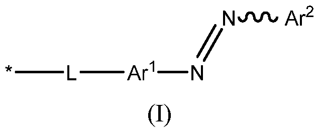


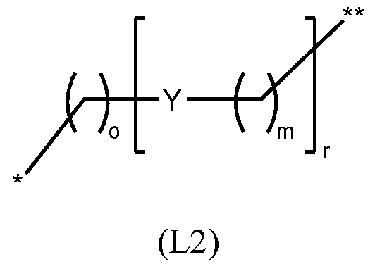


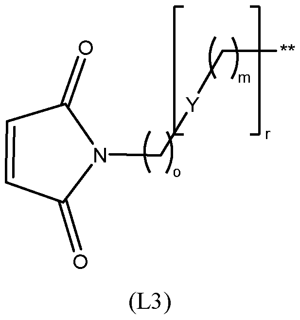
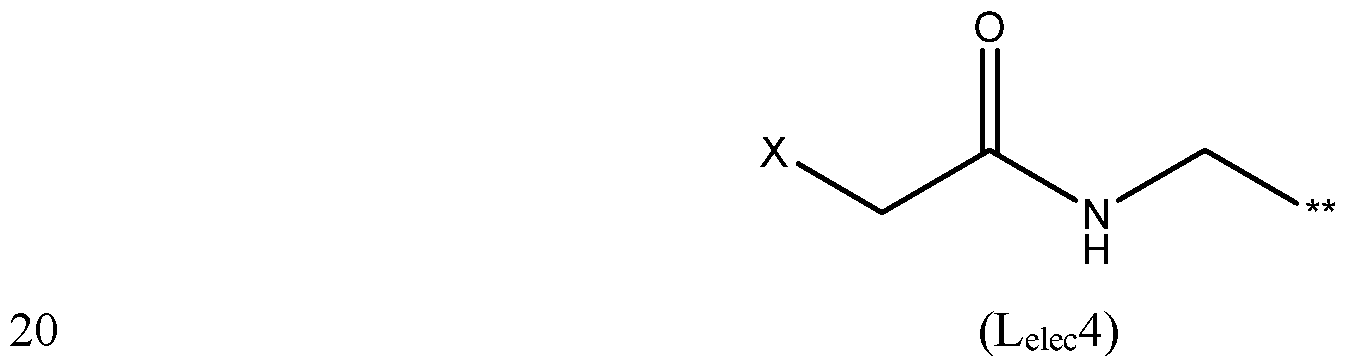


Claims


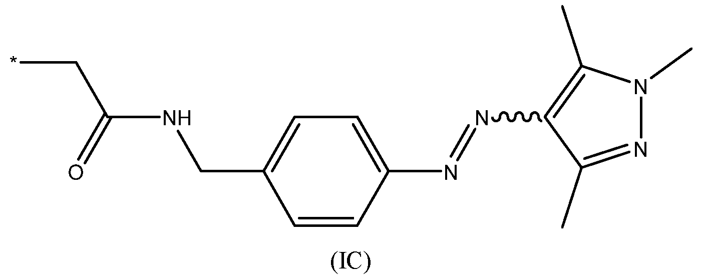


Priority Applications (2)
| Application Number | Priority Date | Filing Date | Title |
|---|---|---|---|
| AU2024326546A AU2024326546A1 (en) | 2023-08-18 | 2024-08-16 | Nanopore |
| IL326651A IL326651A (en) | 2023-08-18 | 2024-08-16 | Nanopore |
Applications Claiming Priority (2)
| Application Number | Priority Date | Filing Date | Title |
|---|---|---|---|
| GB2312709.5 | 2023-08-18 | ||
| GBGB2312709.5A GB202312709D0 (en) | 2023-08-18 | 2023-08-18 | Nanopore |
Publications (1)
| Publication Number | Publication Date |
|---|---|
| WO2025040887A1 true WO2025040887A1 (en) | 2025-02-27 |
Family
ID=88189869
Family Applications (1)
| Application Number | Title | Priority Date | Filing Date |
|---|---|---|---|
| PCT/GB2024/052165 Pending WO2025040887A1 (en) | 2023-08-18 | 2024-08-16 | Nanopore |
Country Status (4)
| Country | Link |
|---|---|
| AU (1) | AU2024326546A1 (en) |
| GB (1) | GB202312709D0 (en) |
| IL (1) | IL326651A (en) |
| WO (1) | WO2025040887A1 (en) |
Cited By (1)
| Publication number | Priority date | Publication date | Assignee | Title |
|---|---|---|---|---|
| CN120795397A (en) * | 2025-09-10 | 2025-10-17 | 天津工业大学 | Transport film based on dithiophene ethylene and preparation method thereof |
Citations (15)
| Publication number | Priority date | Publication date | Assignee | Title |
|---|---|---|---|---|
| US6464842B1 (en) | 1999-06-22 | 2002-10-15 | President And Fellows Of Harvard College | Control of solid state dimensional features |
| WO2003003446A2 (en) | 2001-06-27 | 2003-01-09 | President And Fellows Of Harvard College | Control of solid state dimensional features |
| WO2005061373A1 (en) | 2003-12-19 | 2005-07-07 | President And Fellows Of Harvard College | Analysis of molecules by translocation through a coated aperture |
| WO2006100484A2 (en) | 2005-03-23 | 2006-09-28 | Isis Innovation Limited | Deliver of molecules to a li id bila |
| US7253434B2 (en) | 2002-10-29 | 2007-08-07 | President And Fellows Of Harvard College | Suspended carbon nanotube field effect transistor |
| US7258838B2 (en) | 1999-06-22 | 2007-08-21 | President And Fellows Of Harvard College | Solid state molecular probe device |
| WO2008102121A1 (en) | 2007-02-20 | 2008-08-28 | Oxford Nanopore Technologies Limited | Formation of lipid bilayers |
| US7466069B2 (en) | 2002-10-29 | 2008-12-16 | President And Fellows Of Harvard College | Carbon nanotube device fabrication |
| US7468271B2 (en) | 2005-04-06 | 2008-12-23 | President And Fellows Of Harvard College | Molecular characterization with carbon nanotube control |
| WO2009020682A2 (en) | 2007-05-08 | 2009-02-12 | The Trustees Of Boston University | Chemical functionalization of solid-state nanopores and nanopore arrays and applications thereof |
| WO2009035647A1 (en) | 2007-09-12 | 2009-03-19 | President And Fellows Of Harvard College | High-resolution molecular graphene sensor comprising an aperture in the graphene layer |
| WO2009077734A2 (en) | 2007-12-19 | 2009-06-25 | Oxford Nanopore Technologies Limited | Formation of layers of amphiphilic molecules |
| WO2012005857A1 (en) | 2010-06-08 | 2012-01-12 | President And Fellows Of Harvard College | Nanopore device with graphene supported artificial lipid membrane |
| WO2013083983A1 (en) | 2011-12-06 | 2013-06-13 | Cambridge Enterprise Limited | Nanopore functionality control |
| EP3771687A1 (en) * | 2019-07-30 | 2021-02-03 | Rijksuniversiteit Groningen | Reversible photo-controlled frac nanopores, modified frac monomers, methods for preparing the same, and uses thereof |
-
2023
- 2023-08-18 GB GBGB2312709.5A patent/GB202312709D0/en not_active Ceased
-
2024
- 2024-08-16 AU AU2024326546A patent/AU2024326546A1/en active Pending
- 2024-08-16 IL IL326651A patent/IL326651A/en unknown
- 2024-08-16 WO PCT/GB2024/052165 patent/WO2025040887A1/en active Pending
Patent Citations (15)
| Publication number | Priority date | Publication date | Assignee | Title |
|---|---|---|---|---|
| US7258838B2 (en) | 1999-06-22 | 2007-08-21 | President And Fellows Of Harvard College | Solid state molecular probe device |
| US6464842B1 (en) | 1999-06-22 | 2002-10-15 | President And Fellows Of Harvard College | Control of solid state dimensional features |
| WO2003003446A2 (en) | 2001-06-27 | 2003-01-09 | President And Fellows Of Harvard College | Control of solid state dimensional features |
| US7253434B2 (en) | 2002-10-29 | 2007-08-07 | President And Fellows Of Harvard College | Suspended carbon nanotube field effect transistor |
| US7466069B2 (en) | 2002-10-29 | 2008-12-16 | President And Fellows Of Harvard College | Carbon nanotube device fabrication |
| WO2005061373A1 (en) | 2003-12-19 | 2005-07-07 | President And Fellows Of Harvard College | Analysis of molecules by translocation through a coated aperture |
| WO2006100484A2 (en) | 2005-03-23 | 2006-09-28 | Isis Innovation Limited | Deliver of molecules to a li id bila |
| US7468271B2 (en) | 2005-04-06 | 2008-12-23 | President And Fellows Of Harvard College | Molecular characterization with carbon nanotube control |
| WO2008102121A1 (en) | 2007-02-20 | 2008-08-28 | Oxford Nanopore Technologies Limited | Formation of lipid bilayers |
| WO2009020682A2 (en) | 2007-05-08 | 2009-02-12 | The Trustees Of Boston University | Chemical functionalization of solid-state nanopores and nanopore arrays and applications thereof |
| WO2009035647A1 (en) | 2007-09-12 | 2009-03-19 | President And Fellows Of Harvard College | High-resolution molecular graphene sensor comprising an aperture in the graphene layer |
| WO2009077734A2 (en) | 2007-12-19 | 2009-06-25 | Oxford Nanopore Technologies Limited | Formation of layers of amphiphilic molecules |
| WO2012005857A1 (en) | 2010-06-08 | 2012-01-12 | President And Fellows Of Harvard College | Nanopore device with graphene supported artificial lipid membrane |
| WO2013083983A1 (en) | 2011-12-06 | 2013-06-13 | Cambridge Enterprise Limited | Nanopore functionality control |
| EP3771687A1 (en) * | 2019-07-30 | 2021-02-03 | Rijksuniversiteit Groningen | Reversible photo-controlled frac nanopores, modified frac monomers, methods for preparing the same, and uses thereof |
Non-Patent Citations (64)
| Title |
|---|
| ALFORD A. JOHN ET AL: "Synthesis and Site-Specific Incorporation of Red-Shifted Azobenzene Amino Acids into Proteins", ORGANIC LETTERS, vol. 17, no. 24, 9 December 2015 (2015-12-09), US, pages 6258 - 6261, XP055606135, ISSN: 1523-7060, DOI: 10.1021/acs.orglett.5b03268 * |
| ALTSCHUL S. F., J MOL EVOL, vol. 36, 1993, pages 290 - 300 |
| ALTSCHUL, S.F ET AL., J MOL BIOL, vol. 215, 1990, pages 403 - 10 |
| ANKENBRUCK, N.COURTNEY, T.NARO, Y.DEITERS, A.: "Optochemical control of biological processes in cells and animals", ANGEW. CHEM. INT. ED., vol. 57, 2018, pages 2768 - 2798, XP055938606, DOI: 10.1002/anie.201700171 |
| BANGHART, M.BORGES, K.ISACOFF, E.TRAUNER, D.KRAMER, R. H.: "Light-activated ion channels for remote control of neuronal firing", NAT. NEUROSCI., vol. 7, 2004, pages 1381 - 1386 |
| BLÉGER, D.SCHWARZ, J.BROUWER, A. M.HECHT, S.: "O-fluoroazobenzenes as readily synthesized photoswitches offering nearly quantitative two-way isomerization with visible light", J. AM. CHEM. SOC., vol. 134, 2012, pages 20597 - 20600 |
| BOOTH, M. J.RESTREPO SCHILD, V.BOX, S. J.BAYLEY, H.: "Light-patterning of synthetic tissues with single droplet resolution", SCI. REP., vol. 7, 2017, pages 1 - 10 |
| BOZOVIC, O.JANKOVIC, B.HAMM, P.: "Using azobenzene photocontrol to set proteins in motion", NAT. REV. CHEM., vol. 6, 2022, pages 112 - 124, XP037689280, DOI: 10.1038/s41570-021-00338-6 |
| BRAHA, O. ET AL.: "Designed protein pores as components for biosensors", CHEM. BIOL., vol. 4, 1997, pages 497 - 505, XP009006124, DOI: 10.1016/S1074-5521(97)90321-5 |
| BREGESTOVSKI P D ET AL: "Photopharmacology: A Brief Review Using the Control of Potassium Channels as an Example", NEUROSCIENCE AND BEHAVIORAL PHYSIOLOGY, CONSULTANTS BUREAU, NEW YORK, NY, US, vol. 49, no. 2, 31 January 2019 (2019-01-31), pages 184 - 191, XP036710534, ISSN: 0097-0549, [retrieved on 20190131], DOI: 10.1007/S11055-019-00713-3 * |
| CALBO, J. ET AL.: "Tuning azoheteroarene photoswitch performance through heteroaryl design", J. AM. CHEM. SOC., vol. 139, 2017, pages 1261 - 1274, XP055846894, DOI: 10.1021/jacs.6b11626 |
| CATTERALL, W. A.: "Ion channel voltage sensors: Structure, function, and pathophysiology", NEURON, vol. 67, 2010, pages 915 - 928 |
| CHANDRAMOULI BALASUBRAMANIAN ET AL: "Introducing an artificial photo-switch into a biological pore: A model study of an engineered [alpha]-hemolysin", BIOCHIMICA ET BIOPHYSICA ACTA, ELSEVIER, AMSTERDAM, NL, vol. 1858, no. 4, 29 December 2015 (2015-12-29), pages 689 - 697, XP029451772, ISSN: 0005-2736, DOI: 10.1016/J.BBAMEM.2015.12.030 * |
| CHANG, C.NIBLACK, B.WALKER, B.BAYLEY, H.: "A photogenerated pore-forming protein", CHEM. BIOL., vol. 2, 1995, pages 391 - 400 |
| D. P. NGUYENR. N. SLADEKL. H. DO, TETRAHEDRON LETTERS, vol. 61, 2020, pages 152196 |
| DANIEL OFFENBARTL-STIEGERT ET AL: "A Light-Triggered Synthetic Nanopore for Controlling Molecular Transport Across Biological Membranes", ANGEWANDTE CHEMIE, WILEY - V C H VERLAG GMBH & CO. KGAA, DE, vol. 134, no. 52, 29 November 2022 (2022-11-29), pages n/a, XP072612801, ISSN: 0044-8249, DOI: 10.1002/ANGE.202210886 * |
| DEVEREUX ET AL., NUCLEIC ACIDS RESEARCH, vol. 12, 1984, pages 387 - 395 |
| E. DE VITAP. SCHÜLERS. LOVELLJ. LOHBECKS. KULLMANNE. RABINOVICHA. SANANESB. HEΒLINGV. HAMONN. PAPO, J MED CHEM, vol. 61, 2018, pages 8859 - 8874 |
| E. SPRUIJT, NAT. NANOTECHNOL, 2018 |
| EMILIANI, V. ET AL.: "Optogenetics for light control of biological systems", NAT. REV. METHODS PRIMERS, vol. 2, 2022 |
| FEHRENTZ, T. ET AL.: "Optical control of L-type Ca2+ channels using a diltiazem photoswitch", NAT. CHEM. BIOL., vol. 14, 2018, pages 764 - 767, XP036850022, DOI: 10.1038/s41589-018-0090-8 |
| FRANK, J. A. ET AL.: "Photoswitchable fatty acids enable optical control of TRPV1", NAT. COMMUN., vol. 6, 2015 |
| GONZALEZ-PEREZ ET AL., LANGMUIR, vol. 25, 2009, pages 10447 - 10450 |
| GOVORUNOVA, E. G.SINESHCHEKOV, O. A.LI, H.SPUDICH, J. L.: "Microbial rhodopsins: diversity, mechanisms, and optogenetic applications", ANNU. REV. BIOCHEM., vol. 86, 2017, pages 845 - 872 |
| GU, L. Q.CHELEY, S.BAYLEY, H.: "Electroosmotic enhancement of the binding of a neutral molecule to a transmembrane pore", PROC. NATL. ACAD. SCI. U.S.A., vol. 100, 2003, pages 15498 - 15503, XP002568387, DOI: 10.1073/pnas.2531778100 |
| HIRSCHI, S.WARD, T. R.MEIER, W. P.MULLER, D. J.FOTIADIS, D.: "Synthetic biology: bottom-up assembly of molecular systems", CHEM. REV., vol. 122, 2022, pages 16294 - 16328 |
| HUANG ET AL., NATURE NANOTECHNOLOGY, vol. 10, 2015, pages 986 - 992 |
| HUANG, H.DELIKANLI, S.ZENG, H.FERKEY, D. M.PRALLE, A.: "Remote control of ion channels and neurons through magnetic-field heating of nanoparticles", NAT. NANOTECHNOL, vol. 5, 2010, pages 602 - 606, XP002744776, DOI: 10.1038/nnano.2010.125 |
| JIANG, S.WU, X.ROMMELFANGER, N. J.OU, Z.HONG, G.: "Shedding light on neurons: optical approaches for neuromodulation", NATL. SCI. REV., vol. 9, 2022 |
| JOHNSON, T. G.SADEGHI-KELISHADI, A.LANGTON, M. J.: "A Photo-responsive transmembrane anion transporter relay", J. AM. CHEM. SOC., vol. 144, 2022, pages 10455 - 10461 |
| K. R. MAHENDRAN, NAT. CHEM., 2016 |
| KERCKHOFFS, A.BO, Z.PENTY, S. E.DUARTE, F.LANGTON, M. J.: "Red-shifted tetra-ortho-halo-azobenzenes for photo-regulated transmembrane anion transport", ORG. BIOMOL. CHEM., vol. 19, 2021, pages 9058 - 9067 |
| KOÇER, A.WALKO, M.MEIJBERG, W.FERINGA, B. L.: "Chemistry: a light-actuated nanovalve derived from a channel protein", SCIENCE, vol. 309, 2005, pages 755 - 758 |
| KRAMER, R. H.CHAMBERS, J. J.TRAUNER, D.: "Photochemical tools for remote control of ion channels in excitable cells", NAT. CHEM. BIOL., vol. 1, 2005, pages 360 - 365 |
| LAM, P. Y. ET AL.: "TRPswitch - a step-function chemo-optogenetic ligand for the vertebrate trpa1 channel", J. AM. CHEM. SOC., vol. 142, 2020, pages 17457 - 17468, XP093017166, DOI: 10.1021/jacs.0c06811 |
| LANGECKER ET AL., SCIENCE, vol. 338, 2012, pages 932 - 936 |
| LEHNINGER, A. L.: "Biochemistry", 1975, WORTH PUBLISHERS, pages: 71 - 92 |
| LEWIS, C. A.: "Ion-concentration dependence of the reversal potential and the single channel conductance of ion channels at the frog neuromuscular junction", J. PHYSIOL., vol. 286, 1979, pages 417 - 445 |
| LI, J. ET AL.: "Metal-organic frameworks as micromotors with tunable engines and brakes", J. AM. CHEM. SOC., vol. 139, 2017, pages 611 - 614 |
| LOUDWIG, S.BAYLEY, H.: "Photoisomerization of an individual azobenzene molecule in water: an on-off switch triggered by light at a fixed wavelength", J. AM. CHEM. SOC., vol. 128, 2006, pages 12404 - 12405 |
| M.A. HOLDENH. BAYLEY, J. AM. CHEM. SOC., vol. 127, 2005, pages 6502 - 6503 |
| MAGLIA, G. ET AL.: "Droplet networks with incorporated protein diodes show collective properties", NAT. NANOTECHNOL., vol. 4, 2009, pages 437 - 440, XP055096697, DOI: 10.1038/nnano.2009.121 |
| MALTAN, L.NAJJAR, H.TIFFNER, A.DERLER, I.: "Deciphering molecular mechanisms and intervening in physiological and pathophysiological processes of Ca2+ signaling mechanisms using optogenetic tools", CELLS, vol. 10, 2021 |
| MONTALMUELLER, PROC. NATL. ACAD. SCI. USA., vol. 69, 1972, pages 3561 - 3566 |
| MUTTER, N. L.VOLARIC, J.SZYMANSKI, W.FERINGA, B. L.MAGLIA, G.: "Reversible photocontrolled nanopore assembly", J. AM. CHEM. SOC., vol. 141, 2019, pages 14356 - 14363 |
| N. TRAN-HOANGT. KODADEK, ACS COMB SCI, vol. 20, 2018, pages 55 - 60 |
| NGUYEN, N. T. ET AL.: "CRAC channel-based optogenetics", CELL CALCIUM, vol. 75, 2018, pages 79 - 88, XP085478531, DOI: 10.1016/j.ceca.2018.08.007 |
| NYNS, E. C. A. ET AL.: "An automated hybrid bioelectronic system for autogenous restoration of sinus rhythm in atrial fibrillation", SCI. TRANSL. MED., vol. 11, 2019, pages 1 - 12 |
| OFFENBARTL-STIEGERT, D.ROTTENSTEINER, A.DOREY, A.HOWORKA, S.: "A light-triggered synthetic nanopore for controlling molecular transport across biological membranes", ANGEW. CHEM. INT. ED., vol. 61, 2022 |
| P.-Y. LAMA. R. THAWANIE. BALDERASA. J. P. WHITED. CHAUDHURIM. J. FUCHTERR. T. PETERSON, J AM CHEM SOC, vol. 142, 2020, pages 17457 - 17468 |
| PRAVDA, L. ET AL.: "ChannelsDB: database of biomacromolecular tunnels and pores", NUCLEIC ACIDS RES., vol. 46, 2018, pages D399 - D405 |
| PULCU, G. S.MIKHAILOVA, E.CHOI, L. S.BAYLEY, H.: "Continuous observation of the stochastic motion of an individual small-molecule walker", NAT. NANOTECHNOL., vol. 10, 2015, pages 76 - 83, XP055612565, DOI: 10.1038/nnano.2014.264 |
| ROBERTSVELLACCIO: "The Peptides: Analysis, Synthesis, Biology, Gross and Meiehofer", vol. 5, 1983, ACADEMIC PRESS, INC., pages: 341 |
| S. AÏT AMIRIC. DEBOUXF. SOUALMIAN. CHAAYAM. LOUETE. DUPLUSS. BETUINGB. NAIT OUMESMARN. MASURIERC. EL AMRI, J MED CHEM, vol. 64, 2021, pages 5667 - 5688 |
| SCHILD, V. R. ET AL.: "Light-patterned current generation in a droplet bilayer array", SCI. REP., vol. 7, 2017, pages 1 - 9 |
| SZYMANSKI, W.YILMAZ, D.KOÇER, A.FERINGA, B. L.: "Bright ion channels and lipid bilayers", ACC. CHEM. RES., vol. 46, 2013, pages 2910 - 2923 |
| TOCHITSKY, I. ET AL.: "How azobenzene photoswitches restore visual responses to the blind retina", NEURON, vol. 92, 2016, pages 100 - 113 |
| VILLAR, G.GRAHAM, A. D.BAYLEY, H.: "A tissue-like printed material", SCIENCE, vol. 340, 2013, pages 48 - 52, XP002770114, DOI: 10.1126/science.1229495 |
| VOLGRAF, M. ET AL.: "Allosteric control of an ionotropic glutamate receptor with an optical switch", NAT. CHEM. BIOL., vol. 2, 2006, pages 47 - 52 |
| VRIENS, J.NILIUS, B.VOETS, T.: "Peripheral thermosensation in mammals", NAT. REV. NEUROSCI., vol. 15, 2014, pages 573 - 589, XP037083906, DOI: 10.1038/nrn3784 |
| WALKER, B.BAYLEY, H.: "Key residues for membrane binding, oligomerization, and pore forming activity of staphylococcal α-hemolysin identified by cysteine scanning mutagenesis and targeted chemical modification", J. BIOL. CHEM., vol. 270, 1995, pages 23065 - 23071, XP002547872, DOI: 10.1074/jbc.270.39.23065 |
| WESTON, C. E.RICHARDSON, R. D.HAYCOCK, P. R.WHITE, A. J. PFUCHTER, M. J.: "Arylazopyrazoles: azoheteroarene photoswitches offering quantitative isomerization and long thermal half-lives", J. AM. CHEM. SOC., vol. 136, 2014, pages 11878 - 11881, XP093191222, DOI: 10.1021/ja505444d |
| XU, X.MEE, T.JIA, X.: "New era of optogenetics: from the central to peripheral nervous system", CRIT. REV. BIOCHEM. MOL. BIOL., vol. 55, 2020, pages 1 - 16 |
| ZHANG, F. ET AL.: "The microbial opsin family of optogenetic tools", CELL, vol. 147, 2011, pages 1446 - 1457, XP028348924, DOI: 10.1016/j.cell.2011.12.004 |
Cited By (2)
| Publication number | Priority date | Publication date | Assignee | Title |
|---|---|---|---|---|
| CN120795397A (en) * | 2025-09-10 | 2025-10-17 | 天津工业大学 | Transport film based on dithiophene ethylene and preparation method thereof |
| CN120795397B (en) * | 2025-09-10 | 2025-11-21 | 天津工业大学 | Dithiophene-ethylene-based transport membrane and its preparation method |
Also Published As
| Publication number | Publication date |
|---|---|
| AU2024326546A1 (en) | 2026-03-12 |
| IL326651A (en) | 2026-04-01 |
| GB202312709D0 (en) | 2023-10-04 |
Similar Documents
| Publication | Publication Date | Title |
|---|---|---|
| US11939359B2 (en) | Mutant pore | |
| Scott et al. | Constructing ion channels from water-soluble α-helical barrels | |
| US20210324020A1 (en) | Mutant lysenin pores | |
| CA2924752C (en) | Method for determining the presence, absence, number or position(s) of one or more post-translational modifications (ptms) in a peptide, polypeptide or protein | |
| EP4070092A1 (en) | Method of characterising a target polypeptide using a nanopore | |
| JP2022518095A (en) | pore | |
| CN103460040A (en) | mutant hole | |
| KR20170042794A (en) | Mutant csgg pores | |
| JP7844455B2 (en) | Modification of nanopore-forming protein oligomers | |
| WO2025040887A1 (en) | Nanopore | |
| KR20260053374A (en) | nanopores | |
| Hosseini et al. | Understanding lipid recognition by protein-mimicking cyclic peptides |
Legal Events
| Date | Code | Title | Description |
|---|---|---|---|
| 121 | Ep: the epo has been informed by wipo that ep was designated in this application |
Ref document number: 24762383 Country of ref document: EP Kind code of ref document: A1 |
|
| WWE | Wipo information: entry into national phase |
Ref document number: 326651 Country of ref document: IL |
|
| WWE | Wipo information: entry into national phase |
Ref document number: AU2024326546 Country of ref document: AU |
|
| WWP | Wipo information: published in national office |
Ref document number: 326651 Country of ref document: IL |
|
| REG | Reference to national code |
Ref country code: BR Ref legal event code: B01A Ref document number: 112026003852 Country of ref document: BR |
|
| ENP | Entry into the national phase |
Ref document number: 2024326546 Country of ref document: AU Date of ref document: 20240816 Kind code of ref document: A |
|
| WWE | Wipo information: entry into national phase |
Ref document number: 1020267008269 Country of ref document: KR |
|
| WWE | Wipo information: entry into national phase |
Ref document number: 2024762383 Country of ref document: EP |
|
| NENP | Non-entry into the national phase |
Ref country code: DE |
|
| WWE | Wipo information: entry into national phase |
Ref document number: 11202601025S Country of ref document: SG |
|
| WWP | Wipo information: published in national office |
Ref document number: 11202601025S Country of ref document: SG |