WO2025037587A1 - 自動車用の制御装置、プログラム、ランプシステム - Google Patents
自動車用の制御装置、プログラム、ランプシステム Download PDFInfo
- Publication number
- WO2025037587A1 WO2025037587A1 PCT/JP2024/028550 JP2024028550W WO2025037587A1 WO 2025037587 A1 WO2025037587 A1 WO 2025037587A1 JP 2024028550 W JP2024028550 W JP 2024028550W WO 2025037587 A1 WO2025037587 A1 WO 2025037587A1
- Authority
- WO
- WIPO (PCT)
- Prior art keywords
- control device
- drive recorder
- vehicle
- camera
- collision
- Prior art date
- Legal status (The legal status is an assumption and is not a legal conclusion. Google has not performed a legal analysis and makes no representation as to the accuracy of the status listed.)
- Pending
Links
Images




Classifications
-
- B—PERFORMING OPERATIONS; TRANSPORTING
- B60—VEHICLES IN GENERAL
- B60Q—ARRANGEMENT OF SIGNALLING OR LIGHTING DEVICES, THE MOUNTING OR SUPPORTING THEREOF OR CIRCUITS THEREFOR, FOR VEHICLES IN GENERAL
- B60Q1/00—Arrangement of optical signalling or lighting devices, the mounting or supporting thereof or circuits therefor
- B60Q1/02—Arrangement of optical signalling or lighting devices, the mounting or supporting thereof or circuits therefor the devices being primarily intended to illuminate the way ahead or to illuminate other areas of way or environments
- B60Q1/04—Arrangement of optical signalling or lighting devices, the mounting or supporting thereof or circuits therefor the devices being primarily intended to illuminate the way ahead or to illuminate other areas of way or environments the devices being headlights
-
- B—PERFORMING OPERATIONS; TRANSPORTING
- B60—VEHICLES IN GENERAL
- B60Q—ARRANGEMENT OF SIGNALLING OR LIGHTING DEVICES, THE MOUNTING OR SUPPORTING THEREOF OR CIRCUITS THEREFOR, FOR VEHICLES IN GENERAL
- B60Q1/00—Arrangement of optical signalling or lighting devices, the mounting or supporting thereof or circuits therefor
- B60Q1/02—Arrangement of optical signalling or lighting devices, the mounting or supporting thereof or circuits therefor the devices being primarily intended to illuminate the way ahead or to illuminate other areas of way or environments
- B60Q1/04—Arrangement of optical signalling or lighting devices, the mounting or supporting thereof or circuits therefor the devices being primarily intended to illuminate the way ahead or to illuminate other areas of way or environments the devices being headlights
- B60Q1/14—Arrangement of optical signalling or lighting devices, the mounting or supporting thereof or circuits therefor the devices being primarily intended to illuminate the way ahead or to illuminate other areas of way or environments the devices being headlights having dimming means
-
- G—PHYSICS
- G07—CHECKING-DEVICES
- G07C—TIME OR ATTENDANCE REGISTERS; REGISTERING OR INDICATING THE WORKING OF MACHINES; GENERATING RANDOM NUMBERS; VOTING OR LOTTERY APPARATUS; ARRANGEMENTS, SYSTEMS OR APPARATUS FOR CHECKING NOT PROVIDED FOR ELSEWHERE
- G07C5/00—Registering or indicating the working of vehicles
-
- G—PHYSICS
- G08—SIGNALLING
- G08G—TRAFFIC CONTROL SYSTEMS
- G08G1/00—Traffic control systems for road vehicles
Definitions
- This disclosure relates to a lamp system for an automobile.
- ADAS Automatic Driver Assistance Systems
- the inventors have studied automobiles equipped with drive recorders and have come to recognize the following issues.
- the distance between the car and the vehicle ahead becomes so close that the headlamp illuminance at the position of the vehicle ahead becomes very high. This can cause the license plate of the vehicle ahead to be blown out in the image recorded by the drive recorder.
- This disclosure has been made in consideration of these problems, and one exemplary purpose of one aspect of the disclosure is to provide a system that can record important information about a subject even in the event of a collision.
- One aspect of the present disclosure relates to a control device that is installed in an automobile equipped with a drive recorder and modularized with the drive recorder's camera.
- the control device processes images from the drive recorder's camera, predicts a collision of the automobile with a vehicle ahead, and outputs a control signal to the outside that triggers a reduction in the brightness of the headlights based on the prediction results.
- important information about the subject can be recorded even in the event of a collision.
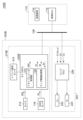
- FIG. 1 is a block diagram of a vehicle according to a first embodiment.
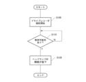
- FIG. 2 is a block diagram of a microcontroller which is a camera ECU. 4 is a flowchart of the headlamp control performed by the camera ECU.
- FIG. 1 is a diagram illustrating the operation of a conventional lamp system. 2 is a diagram illustrating the operation of the lamp system of FIG. 1.
- FIG. 11 is a block diagram of a vehicle according to a second embodiment.
- FIG. 11 is a block diagram of a vehicle according to a third embodiment.
- the control device is mounted on an automobile equipped with a drive recorder and modularized with the drive recorder's camera.
- the control device processes images from the drive recorder's camera, predicts a collision of the automobile with a vehicle ahead, and outputs a control signal to the outside that triggers a reduction in the brightness of the headlamps based on the prediction results.
- control device may predict a collision based on images from a drive recorder camera. It is possible to estimate the distance to the subject based on the size of the subject captured in the camera image and changes in the size, and the information obtained can be used to predict a collision.
- the automobile may be equipped with a driving assistance system.
- the camera of the drive recorder may also serve as a sensor of the driving assistance system. By sharing the sensor of the driving assistance system with the camera of the drive recorder, the cost for the function can be reduced.
- the vehicle may be equipped with a driving assistance system.
- the control device may predict a collision based on the output of sensors in the driving assistance system. Examples of such sensors include millimeter wave radar, LiDAR (Light Detection and Ranging), ToF (Time of Flight) cameras, stereo cameras, and monocular cameras.
- control device may generate shading information for defining the light distribution of the headlamps based on images from the camera of the drive recorder.
- the automobile may be equipped with a driving assistance system.
- the control device may generate shading information for defining the light distribution of the headlamps based on the output of a sensor of the driving assistance system.
- the lamp system includes a drive recorder and a headlamp.
- the drive recorder may include a camera and any of the control devices described above.
- (Embodiment 1) 1 is a block diagram of an automobile 100 according to a first embodiment.
- the automobile 100 includes a drive recorder 210, a headlamp 220, and a vehicle-side system 110.
- the drive recorder 210, the headlamp 220, and the vehicle-side system 110 are connected via a vehicle bus 106.
- the vehicle bus 106 may be one bus or multiple buses.
- the type of the vehicle bus 106 is not particularly limited, but examples include a controller area network (CAN) and a local interconnect network (LIN).
- CAN controller area network
- LIN local interconnect network
- the drive recorder 210 captures images of the area in front of the vehicle and records the captured images.
- the recording medium 114 is provided in the vehicle-side system 110.
- the recording medium 114 is an SD card, SSD (Solid State Drive), flash memory, etc., and records the images generated by the drive recorder.
- the recording medium 114 is provided on the vehicle side, but it may also be provided in the drive recorder 210.
- the drive recorder 210 includes a camera 212, an event detection sensor 214, and a camera ECU 300.
- the camera ECU 300 includes a drive recorder processing unit 310.
- the drive recorder processing unit 310 transfers image data IMG output from the camera 212 to the vehicle-side system 110.
- the event detection sensor 214 includes a gyro sensor, a gravity sensor, and the like.
- the drive recorder processing unit 310 detects a predetermined event, such as a large vibration or a fall of the vehicle body, according to the output of the event detection sensor 214. When the drive recorder processing unit 310 detects an event, it switches the recording mode.
- Camera ECU 300 may be a control board configured by combining a microcontroller (MCU) and other hardware, and a processor executes software programs to perform various processes.
- MCU microcontroller
- the blocks shown inside camera ECU 300 in the block diagram are convenient and schematic representations of units of processing and functions implemented in camera ECU 300.
- the headlamp 220 includes a low beam unit 222, a high beam unit 224, and a lamp ECU 226.
- the lamp ECU 226 receives an instruction signal S1 for turning on and off the low beam and high beam from the vehicle ECU 112.
- an instruction Hi to turn on the low beam it turns on the low beam unit 222, and when it receives an instruction Lo to turn on the high beam, it turns on the high beam unit 224.
- the headlamp 220 may be equipped with an ADB function that adaptively controls light distribution according to targets in front of the vehicle.
- the high beam unit 224 is a variable light distribution lamp, and can provide localized shading areas within the light distribution pattern.
- the lamp ECU 226 receives shading information S2 from the vehicle-side system 110.
- the shading information S2 includes data that specifies areas to be shading within the light distribution.
- the lamp ECU 226 controls the high beam unit 224 based on the shading information S2, and illuminates the area in front of the vehicle with glare-free high beams.
- the drive recorder 210 includes a camera 212, an event detection sensor 214, and a control device 300.
- the control device 300 will be referred to as the camera electronic control unit (ECU).
- the camera ECU 300 is modularized together with the camera 212 of the drive recorder 210.
- the vehicle-side system 110 includes a vehicle ECU 112 and a recording medium 114.
- the vehicle ECU 112 writes the image data IMG received from the drive recorder 210 to the recording medium 114.
- the automobile 100 may be equipped with a driving assistance system, which may be implemented as part of the vehicle-side system 110, which includes an ADAS sensor 116.
- ADAS sensor 116 include a millimeter-wave radar, a LiDAR (Light Detection and Ranging), a ToF (Time of Flight) camera, a stereo camera, and a monocular camera.
- the camera 212 of the drive recorder 210 may function as a sensor for ADAS.
- the drive recorder 210 and the headlamps 220 are designed completely independently, but this embodiment differs from the conventional one in that the camera ECU 300 of the drive recorder 210 executes some of the processing related to the control of the headlamps 220. In other words, it can be said that the drive recorder 210 and the headlamps 220 form the lamp system 200.
- the control of the headlamp 220 by the drive recorder 210 is explained below.
- the camera ECU 300 includes a lamp-related processing unit (lamp-related function) 320.
- the lamp-related processing unit 320 predicts a collision of the automobile 100 equipped with the lamp system 200 with a vehicle ahead, and generates a control signal (dimming instruction) S3 that triggers a reduction in the brightness of the headlamps 220 in response to the prediction, and outputs the signal to the outside.
- the dimming command S3 is supplied to the lamp ECU 226 via the vehicle bus 106 or via other control lines (not shown). In response to the dimming command S3, the lamp ECU 226 reduces the brightness of the currently lit lamps (222, 224).
- the microcontroller 800 includes a processor 810, a non-volatile memory 820, a memory 830, and an interface circuit 840.
- the non-volatile memory 820 is a flash memory, and is a storage medium for storing the above-mentioned software program 850 executed by the processor 810.
- the processor 810 loads the software program 850 into the memory 830 at startup and executes the instructions of the software program 850.
- the interface circuit 840 may include a serial interface such as a UART (Universal Asynchronous Receiver and Transmitter), a three-wire serial interface, an I2C bus interface, a CAN interface, a GPIO, an A/D converter, a D/A converter, and the like.
- the components of the microcontroller 800 may be built into a single IC package, or may be a microcomputer board in which several IC packages are mounted on a printed circuit board.
- FIG. 3 is a flow chart of the headlamp 220 by the camera ECU 300.
- the drive recorder 210 starts taking pictures (S100).
- the camera ECU 300 judges the possibility of the automobile 100 colliding with the vehicle ahead (S110). If it judges that the possibility of a collision is low (not present) (N in S110), it continues to judge the possibility of a collision. If it judges that the possibility of a collision is high (present) (Y in S110), it issues a dimming command S3. In response to this dimming command S3, the brightness of the headlamp 220 is reduced (S120).
- FIG. 4 is a diagram explaining the operation of a conventional lamp system.
- FIG. 4 shows a driving scene immediately before a collision.
- a low beam 4 with a constant brightness was irradiated on the vehicle 2 ahead, regardless of the distance to the vehicle 2 ahead.
- the illuminance at the rear end face of the vehicle 2 ahead increases, and the pixel value of the image of the vehicle ahead recorded by the drive recorder, which captures the light reflected from the vehicle 2 ahead, increases, causing the vehicle 2 ahead to appear overexposed.
- important information that should be recorded by the drive recorder such as the license plate, will be lost.
- FIG. 5 is a diagram explaining the operation of the lamp system in FIG. 1.
- the top part of FIG. 5 shows a normal driving scene, in which the low beam unit 222 emits light at a predetermined brightness, and low beam 4a that meets the legal light distribution requirements is irradiated in front of the vehicle.
- the camera ECU 300 determines that the possibility of a collision with the vehicle 2 ahead has increased. Based on this determination, the emission brightness of the low beam unit 222 is reduced, and the low beam 4b becomes darker. As a result, at the moment of collision shown in the bottom of Figure 5, the illuminance at the vehicle 2 ahead is lowered, and the pixel value of the image of the vehicle ahead recorded by the drive recorder based on the reflected light is smaller than in Figure 4. This makes it possible to suppress overexposure and prevent the loss of important information such as license plates.
- the lamp-related processing unit 320 of the camera ECU 300 predicts a collision based on the image IMG of the camera 212.
- the camera ECU 300 can receive vehicle speed information from the vehicle ECU 112 via the vehicle bus 106.
- the lamp-related processing unit 320 can predict a collision based on the automobile 100 and the size of an object (vehicle ahead) captured in the image IMG from the camera 212.
- the camera ECU 300 can estimate the distance to the vehicle ahead based on the size of the vehicle ahead in the image IMG.
- a collision may be predicted based on the relative relationship between the estimated distance and the stopping distance determined by the vehicle speed.
- the distance to the object may be estimated based on the position at which the object is captured.
- collision prediction method is not limited to this, and any publicly known or future available technology may be used.
- the lamp-related processing unit 320 may process the image IMG from the camera 212, determine the position and type of the target object in front of the vehicle, and generate the shading information S2.
- the camera 212 for the drive recorder may also serve as a sensor for ADB control. This can reduce the cost of the lamp system 200.
- One or both of the shading information S2 and the dimming command S3 generated by the camera ECU 300 may be sent from the vehicle ECU 112 to the lamp ECU 226 after passing through the vehicle ECU 112.
- one or both of the shading information S2 and the dimming command S3 may be sent directly from the camera ECU 300 to the headlamp 220.
- (Embodiment 2) 6 is a block diagram of an automobile 100A according to the second embodiment.
- the processing of a lamp-related processing unit 320A of a camera ECU 300A is different between the second embodiment and the first embodiment. Specifically, the lamp-related processing unit 320A predicts a collision of the automobile 100 (host vehicle) with a vehicle ahead based on the output (sensor information) S4 of the ADAS sensor 116, not on the image IMG generated by the camera 212.
- the sensor information S4 generated by the ADAS sensor 116 is supplied to the lamp-related processing unit 320A via the vehicle bus 106.
- the lamp-related processing unit 320A predicts a collision based on the sensor information S4, and when the possibility of a collision increases, generates a control signal (dimming instruction) S3, which is a trigger to reduce the brightness of the headlamp 220.
- the rest is the same as in embodiment 1.
- the same effects as those of the first embodiment can be obtained.
- the sensor information S4 generated by the ADAS sensor 116 the accuracy of collision prediction can be improved.
- (Embodiment 3) 7 is a block diagram of an automobile 100B according to a third embodiment.
- the ADAS sensor 116 is provided on the lamp system 200B side.
- the ADAS sensor 116 may be built in the drive recorder 210B.
- the ADAS sensor 116 may be built in the headlamp 220.
- the lamp-related processing unit 320B predicts a collision based on the sensor information S4 generated by the ADAS sensor 116 provided on the lamp system 200B side, and when the possibility of a collision increases, generates a control signal (dimming instruction) S3, which is a trigger to reduce the brightness of the headlamp 220.
- the rest is the same as in embodiment 2.
- the lamp-related processing units 320A and 320B may predict a collision based on both the sensor information S4 and the image IMG generated by the camera 212.
- the lamp-related processing unit 320 may generate the light blocking information S2 based on the sensor information S4 generated by the ADAS sensor 116.
- This disclosure relates to a lamp system for an automobile.
Landscapes
- Physics & Mathematics (AREA)
- General Physics & Mathematics (AREA)
- Engineering & Computer Science (AREA)
- Mechanical Engineering (AREA)
- Lighting Device Outwards From Vehicle And Optical Signal (AREA)
Abstract
カメラECU(300)は、ドライブレコーダ(210)を備える自動車(100)に搭載され、ドライブレコーダ(210)のカメラ(212)とともにモジュール化される。制御装置(300)は、ドライブレコーダ(210)のカメラ(212)の画像IMGを処理するとともに、前方車への自動車(100)の衝突を予測し、当該予測に応答してヘッドランプ(220)の輝度を低下させるトリガである制御信号(減光指示)S3を生成し、外部に出力する。
Description
本開示は、自動車用のランプシステムに関する。
交通事故の発生時の状況の記録、あるいはあおり運転などの危険行為の記録を目的として、ドライブレコーダが取り付けられる自動車が増えている。また、先進運転支援システム(ADAS:Automatic Driver-Assistance System)を装備する自動車も増加している。
本発明者は、ドライブレコーダが取り付けられた自動車について検討した結果、以下の課題を認識するに至った。
自動車が前方車両に衝突するシーンでは、自動車と前方車両の距離が近づくため、前方車両の位置におけるヘッドランプの照度が非常に高くなる。これにより、ドライブレコーダに記録される画像は、前方車両のナンバープレートが白飛びする可能性がある。
本開示は係る課題に鑑みてなされたものであり、そのある態様の例示的な目的のひとつは、衝突時においても被写体の重要な情報を記録可能なシステムの提供にある。
本開示のある態様は、ドライブレコーダを備える自動車に搭載され、ドライブレコーダのカメラとともにモジュール化される制御装置に関する。制御装置は、ドライブレコーダのカメラの画像を処理するとともに、前方車への自動車の衝突を予測し、予測結果にもとづいてヘッドランプの輝度を低下させるトリガとなる制御信号を外部に出力する。
なお、以上の構成要素を任意に組み合わせたもの、構成要素や表現を、方法、装置、システムなどの間で相互に置換したものもまた、本発明あるいは本開示の態様として有効である。さらに、この項目(課題を解決するための手段)の記載は、本発明の欠くべからざるすべての特徴を説明するものではなく、したがって、記載されるこれらの特徴のサブコンビネーションも、本発明たり得る。
本開示のある態様によれば、衝突時においても被写体の重要な情報を記録できる。
(実施形態の概要)
本開示のいくつかの例示的な実施形態の概要を説明する。この概要は、後述する詳細な説明の前置きとして、実施形態の基本的な理解を目的として、1つまたは複数の実施形態のいくつかの概念を簡略化して説明するものであり、発明あるいは開示の広さを限定するものではない。またこの概要は、考えられるすべての実施形態の包括的な概要ではなく、実施形態の欠くべからざる構成要素を限定するものではない。便宜上、「一実施形態」は、本明細書に開示するひとつの実施形態(実施例や変形例)または複数の実施形態(実施例や変形例)を指すものとして用いる場合がある。
本開示のいくつかの例示的な実施形態の概要を説明する。この概要は、後述する詳細な説明の前置きとして、実施形態の基本的な理解を目的として、1つまたは複数の実施形態のいくつかの概念を簡略化して説明するものであり、発明あるいは開示の広さを限定するものではない。またこの概要は、考えられるすべての実施形態の包括的な概要ではなく、実施形態の欠くべからざる構成要素を限定するものではない。便宜上、「一実施形態」は、本明細書に開示するひとつの実施形態(実施例や変形例)または複数の実施形態(実施例や変形例)を指すものとして用いる場合がある。
一実施形態に係る制御装置は、ドライブレコーダを備える自動車に搭載され、ドライブレコーダのカメラとともにモジュール化される。制御装置は、ドライブレコーダのカメラの画像を処理するとともに、前方車への自動車の衝突を予測し、予測結果にもとづいてヘッドランプの輝度を低下させるトリガとなる制御信号を外部に出力する。
この構成では、衝突直前において前方車と自車の距離が近くなると、ヘッドランプの輝度が低下する。これにより、前方車における照度が低下するため、ドライブレコーダが記録する画像の白飛びを防止でき、ひいては衝突時において被写体の重要な情報を記録できる。
一実施形態において、制御装置は、ドライブレコーダのカメラの画像にもとづいて、衝突を予測してもよい。カメラの画像に写る被写体の大きさやその変化などにもとづいて、被写体までの距離を推定することが可能であり、そこで得られた情報を衝突の予測に利用できる。
一実施形態において、自動車は、運転支援システムを備えてもよい。ドライブレコーダのカメラは、運転支援システムのセンサを兼ねていてもよい。運転支援システムのセンサとドライブコーダのカメラを兼用することで、機能に対するコストを下げることができる。
一実施形態において、自動車は、運転支援システムを備えてもよい。制御装置は、運転支援システムのセンサの出力にもとづいて、衝突を予測してもよい。こうしたセンサは、ミリ波レーダ、LiDAR(Light Detection and Ranging)、ToF(Time of Flight)カメラ、ステレオカメラや単眼カメラなどが例示される。
一実施形態において、制御装置は、ドライブレコーダのカメラの画像にもとづいて、ヘッドランプの配光を規定するための遮光情報を生成してもよい。
一実施形態において、自動車は、運転支援システムを備えてもよい。制御装置は、運転支援システムのセンサの出力にもとづいて、ヘッドランプの配光を規定するための遮光情報を生成してもよい。
一実施形態に係るランプシステムは、ドライブレコーダと、ヘッドランプと、を備える。ドライブレコーダは、カメラと、上述のいずれかに記載の制御装置と、を備えてもよい。
(実施形態)
以下、好適な実施の形態について図面を参照しながら説明する。各図面に示される同一または同等の構成要素、部材、処理には、同一の符号を付するものとし、適宜重複した説明は省略する。また、実施の形態は、開示を限定するものではなく例示であって、実施の形態に記述されるすべての特徴やその組み合わせは、必ずしも開示の本質的なものであるとは限らない。
以下、好適な実施の形態について図面を参照しながら説明する。各図面に示される同一または同等の構成要素、部材、処理には、同一の符号を付するものとし、適宜重複した説明は省略する。また、実施の形態は、開示を限定するものではなく例示であって、実施の形態に記述されるすべての特徴やその組み合わせは、必ずしも開示の本質的なものであるとは限らない。
(実施形態1)
図1は、実施形態1に係る自動車100のブロック図である。自動車100は、ドライブレコーダ210、ヘッドランプ220、車両側システム110を備える。ドライブレコーダ210、ヘッドランプ220および車両側システム110は、ビークルバス106を介して接続される。ビークルバス106は、ひとつのバスであってもよいし、複数のバスであってもよい。ビークルバス106の種類は特に限定されないが、CAN(Controller Area Network)やLIN(Local Interconnect Network)などが例示される。
図1は、実施形態1に係る自動車100のブロック図である。自動車100は、ドライブレコーダ210、ヘッドランプ220、車両側システム110を備える。ドライブレコーダ210、ヘッドランプ220および車両側システム110は、ビークルバス106を介して接続される。ビークルバス106は、ひとつのバスであってもよいし、複数のバスであってもよい。ビークルバス106の種類は特に限定されないが、CAN(Controller Area Network)やLIN(Local Interconnect Network)などが例示される。
ドライブレコーダ210は車両前方を撮影し、撮影した画像を記録する。この例では、記録媒体114は、車両側システム110に設けられている。記録媒体114はSDカードやSSD(Solid State Drive)、フラッシュメモリなどであり、ドライブレコーダが生成する画像を記録する。図1のブロック図では、記録媒体114が車両側に設けられているが、ドライブレコーダ210に設けられてもよい。
ドライブレコーダ210は、カメラ212、イベント検知センサ214およびカメラECU300を含む。
カメラECU300は、ドライブレコーダ処理部310を含む。ドライブレコーダ処理部310は、カメラ212から出力される画像データIMGを車両側システム110に転送する。イベント検知センサ214は、ジャイロセンサや重力センサなどを含む。ドライブレコーダ処理部310は、イベント検知センサ214の出力に応じて、所定のイベント、たとえば車体の大きな振動や転倒などを検出する。ドライブレコーダ処理部310は、イベントを検出すると、録画モードを切り替えたりする。
カメラECU300は、マイクロコントローラ(MCU)と、その他のハードウェアを組み合わせて構成される制御ボードであってもよく、プロセッサがソフトウェアプログラムを実行することにより、さまざまな処理を実行する。ブロック図においてカメラECU300の内側に示されるブロックは、カメラECU300に実装される処理・機能の単位を便宜的、模式的に表したものである。
ヘッドランプ220は、ロービームユニット222、ハイビームユニット224、ランプECU226を備える。
ランプECU226は、車両ECU112から、ロービームおよびハイビームの点消灯の指示信号S1を受ける。ランプECU226は、ロービームの点灯指示Hiを受けると、ロービームユニット222を点灯し、ハイビームの点灯指示Loを受けると、ハイビームユニット224を点灯する。
ヘッドランプ220は、車両前方の物標に応じて配光を適応的に制御するADB機能を備えてもよい。ハイビームユニット224は配光可変ランプであり、配光パターン内に局所的な遮光部を設けることができる。ランプECU226は、車両側システム110から、遮光情報S2を受ける。遮光情報S2は、配光内で遮光すべき領域を規定するデータを含む。ランプECU226は、遮光情報S2にもとづいて、ハイビームユニット224を制御し、グレアフリーのハイビームで、車両前方を照射する。
ドライブレコーダ210は、カメラ212、イベント検知センサ214および制御装置300を備える。以下、制御装置300を、カメラ電子制御ユニット(ECU:Electronic Control Unit)と称する。カメラECU300は、ドライブレコーダ210のカメラ212とともにモジュール化される。
車両側システム110は、車両ECU112および記録媒体114を含む。車両ECU112は、ドライブレコーダ210から受信した画像データIMGを記録媒体114に書込む。
自動車100は、運転支援システムを備えてもよく、運転支援システムは、車両側システム110の一部として実装することができ、車両側システム110は、ADASセンサ116を備える。ADASセンサ116は、ミリ波レーダ、LiDAR(Light Detection and Ranging)、ToF(Time of Flight)カメラ、ステレオカメラや単眼カメラなどが例示される。あるいは、ADASセンサ116に代えて、あるいはそれに加えて、ドライブレコーダ210のカメラ212が、ADAS用のセンサとして機能してもよい。
一般的には、ドライブレコーダ210とヘッドランプ220は、完全に独立して設計されるが、本実施の形態においては、ドライブレコーダ210のカメラECU300が、ヘッドランプ220の制御に関連する処理の一部を実行する点において、従来と異なっている。つまり、ドライブレコーダ210およびヘッドランプ220が、ランプシステム200を形成している言える。
以下、ドライブレコーダ210によるヘッドランプ220の制御について説明する。
カメラECU300は、ランプ関連処理部(ランプ関連機能)320を備える。ランプ関連処理部320は、ランプシステム200を搭載する自動車100の、前方車への衝突を予測し、当該予測に応答してヘッドランプ220の輝度を低下させるトリガとなる制御信号(減光指示)S3を生成し、外部に出力する。
減光指示S3は、ビークルバス106を経由して、あるいは図示しないその他の制御線を経由して、ランプECU226に供給される。ランプECU226は、減光指示S3に応答して、現在、点灯中のランプ(222,224)の輝度を低下させる。
図2は、カメラECU300であるマイクロコントローラ800のブロック図である。マイクロコントローラ800は、プロセッサ810、不揮発性メモリ820、メモリ830、インタフェース回路840を備える。不揮発性メモリ820はフラッシュメモリであり、プロセッサ810が実行する上述のソフトウェアプログラム850を格納する記憶媒体である。プロセッサ810は、起動時にソフトウェアプログラム850をメモリ830にロードし、ソフトウェアプログラム850の命令を実行する。インタフェース回路840は、UART(Universal Asynchronous Receiver and Transmitter)、3線式シリアル・インタフェース、I2Cバス・インタフェースなどのシリアルインタフェース、CANインタフェース、GPIO、A/DコンバータやD/Aコンバータなどを含みうる。マイクロコントローラ800の構成要素は1つのICパッケージに内蔵されていてもよいし、いくつかのICパッケージがプリント基板上に実装されてなるマイコンボードであってもよい。
図3は、カメラECU300によるヘッドランプ220のフローチャートである。ドライブレコーダ210による撮影が開始する(S100)。カメラECU300は、自動車100の前方車への衝突の可能性を判定する(S110)。そして衝突の可能性が低い(ない)と判定した場合(S110のN)、衝突の可能性を判定し続ける。衝突の可能性が高い(ある)と判定した場合(S110のY)、減光指示S3を発生する。この減光指示S3に応答して、ヘッドランプ220の輝度が低下する(S120)
以上がランプシステム200の構成である。
続いて、ドライブレコーダ付きのヘッドランプシステムにおいて生ずる問題を説明する。
図4は、従来のランプシステムの動作を説明する図である。図4には、衝突直前の走行シーンが示される。従来では、前方車2との距離によらずに、一定の輝度のロービーム4が、前方車2に照射されていた。この場合、前方車2との距離が近づくにしたがって、前方車2の後端面における照度が高くなり、前方車2からの反射光を撮影するドライブレコーダの前方車の画像の画素値が大きくなり、前方車2が白飛びして写ってしまう。つまり、ドライブレコーダで記録すべきナンバープレートなどの重要な情報が欠落する可能性がある。
図5は、図1のランプシステムの動作を説明する図である。図5の最上段は通常の走行シーンであり、ロービームユニット222は所定の輝度で発光しており、法定の配光要件を満たすロービーム4aが車両前方に照射されている。
図5の中段に示す様に、前方車2との距離が近くなると、カメラECU300は、前方車2との衝突の可能性が高まったと判定する。この判定にもとづき、ロービームユニット222の発光輝度が下げられ、ロービーム4bは暗くなる。これにより、図5の下段に示す衝突の瞬間において、前方車2における照度が低くなるため、その反射光にもとづくドライブレコーダの前方車の画像の画素値が、図4に比べて小さくなる。これにより、白飛びを抑制し、ナンバープレートなどの重要な情報の欠落を防止できる。
本実施形態において、カメラECU300のランプ関連処理部320は、カメラ212の画像IMGにもとづいて、衝突を予測する。カメラECU300は、車両ECU112からビークルバス106経由で車速情報を受信可能である。ランプ関連処理部320は、自動車100と、カメラ212からの画像IMGに写る物体(前方車)の大きさと、にもとづいて、衝突を予測することができる。具体的には、カメラECU300は、画像IMG中の前方車の大きさにもとづいて、前方車までの距離を推定できる。そして推定した距離と、車速で決まる停止距離との相対的な関係にもとづいて、衝突を予測してもよい。画像IMGに写る物体の大きさに加えて、またはそれに代えて、物体の写っている位置にもとづいて、物体までの距離を推定してもよい。
なお、衝突予測の手法はこれに限定されず、公知の、あるいは将来利用可能な技術を用いてもよい。
ランプ関連処理部320は、カメラ212の画像IMGを処理し、車両前方の物標の位置および種類を判定し、遮光情報S2を生成してもよい。つまり、ドライブレコーダ用のカメラ212は、ADB制御のためのセンサを兼ねてもよい。これにより、ランプシステム200のコストを下げることができる。
カメラECU300が生成した遮光情報S2および減光指示S3の一方、あるいは両方は、車両ECU112を経由した後に、車両ECU112からランプECU226に対して供給されてもよい。あるいは遮光情報S2および減光指示S3の一方、あるいは両方は、カメラECU300からヘッドランプ220に対して直接供給されてもよい。
(実施形態2)
図6は、実施形態2に係る自動車100Aのブロック図である。実施形態2と実施形態1とでは、カメラECU300Aのランプ関連処理部320Aの処理が異なっている。具体的には、ランプ関連処理部320Aは、カメラ212が生成する画像IMGではなく、ADASセンサ116の出力(センサ情報)S4にもとづいて、自動車100(自車)の前方車への衝突を予測する。
図6は、実施形態2に係る自動車100Aのブロック図である。実施形態2と実施形態1とでは、カメラECU300Aのランプ関連処理部320Aの処理が異なっている。具体的には、ランプ関連処理部320Aは、カメラ212が生成する画像IMGではなく、ADASセンサ116の出力(センサ情報)S4にもとづいて、自動車100(自車)の前方車への衝突を予測する。
具体的には、ADASセンサ116が生成する生成するセンサ情報S4は、ビークルバス106を経由してランプ関連処理部320Aに供給される。ランプ関連処理部320Aは、センサ情報S4にもとづいて、衝突を予測し、衝突の可能性が高まると、ヘッドランプ220の輝度を低下させるトリガである制御信号(減光指示)S3を発生する。その他については実施形態1と同様である。
実施形態2によれば、実施形態1と同様の効果が得られる。またADASセンサ116が生成するセンサ情報S4を利用することで、衝突の予測の精度を高めることができる。
(実施形態3)
図7は、実施形態3に係る自動車100Bのブロック図である。実施形態3では、ADASセンサ116が、ランプシステム200B側に設けられている。たとえばADASセンサ116は、ドライブレコーダ210Bに内蔵されてもよい。あるいは、ADASセンサ116は、ヘッドランプ220に内蔵されてもよい。
図7は、実施形態3に係る自動車100Bのブロック図である。実施形態3では、ADASセンサ116が、ランプシステム200B側に設けられている。たとえばADASセンサ116は、ドライブレコーダ210Bに内蔵されてもよい。あるいは、ADASセンサ116は、ヘッドランプ220に内蔵されてもよい。
ランプ関連処理部320Bは、ランプシステム200B側に設けられたADASセンサ116が生成するセンサ情報S4にもとづいて、衝突を予測し、衝突の可能性が高まると、ヘッドランプ220の輝度を低下させるトリガである制御信号(減光指示)S3を発生する。その他については実施形態2と同様である。
なお、実施形態2、3において、ランプ関連処理部320A,320Bは、センサ情報S4と、カメラ212が生成する画像IMGの両方にもとづいて、衝突の予測を行ってもよい。
(変形例)
実施形態1~3において、ランプ関連処理部320は、ADASセンサ116が生成するセンサ情報S4にもとづいて、遮光情報S2を生成してもよい。
実施形態1~3において、ランプ関連処理部320は、ADASセンサ116が生成するセンサ情報S4にもとづいて、遮光情報S2を生成してもよい。
実施形態は例示であり、それらの各構成要素や各処理プロセスの組み合わせにさまざまな変形例が存在すること、またそうした変形例も本開示または本発明の範囲に含まれることは当業者に理解されるところである。
本開示は、自動車用のランプシステムに関する。
100 自動車
110 車両側システム
112 車両ECU
114 記録媒体
116 ADASセンサ
106 ビークルバス
200 ランプシステム
210 ドライブレコーダ
212 カメラ
214 イベント検知センサ
220 ヘッドランプ
222 ロービームユニット
224 ハイビームユニット
226 ランプECU
300 カメラECU
310 ドライブレコーダ処理部
320 ランプ関連処理部
S2 遮光情報
S3 制御信号(減光指示)
S4 センサ情報
110 車両側システム
112 車両ECU
114 記録媒体
116 ADASセンサ
106 ビークルバス
200 ランプシステム
210 ドライブレコーダ
212 カメラ
214 イベント検知センサ
220 ヘッドランプ
222 ロービームユニット
224 ハイビームユニット
226 ランプECU
300 カメラECU
310 ドライブレコーダ処理部
320 ランプ関連処理部
S2 遮光情報
S3 制御信号(減光指示)
S4 センサ情報
Claims (8)
- ドライブレコーダを備える自動車に搭載され、前記ドライブレコーダのカメラとともにモジュール化される制御装置であって、
前記ドライブレコーダのカメラの画像を処理するとともに、前方車への前記自動車の衝突を予測し、予測結果にもとづいて、ヘッドランプの輝度を低下させるトリガとなる制御信号を外部に出力することを特徴とする制御装置。 - 前記ドライブレコーダのカメラの画像にもとづいて、前記衝突を予測することを特徴とする請求項1に記載の制御装置。
- 前記自動車は、運転支援システムを備え、
前記制御装置は、前記ドライブレコーダのカメラは、前記運転支援システムのセンサを兼ねていることを特徴とする請求項2に記載の制御装置。 - 前記自動車は、運転支援システムを備え、
前記制御装置は、前記運転支援システムのセンサの出力にもとづいて、前記衝突を予測することを特徴とする請求項1に記載の制御装置。 - 前記制御装置は、前記ドライブレコーダのカメラの画像にもとづいて、前記ヘッドランプの配光を規定するための遮光情報を生成することを特徴とする請求項1から4のいずれかに記載の制御装置。
- 前記自動車は、運転支援システムを備え、
前記制御装置は、前記運転支援システムのセンサの出力にもとづいて、前記ヘッドランプの配光を規定するための遮光情報を生成することを特徴とする請求項1から4のいずれかに記載の制御装置。 - ドライブレコーダと、
ヘッドランプと、
を備え、
前記ドライブレコーダは、
カメラと、
請求項1から4のいずれかに記載の制御装置と、
を備えることを特徴とするランプシステム。 - 制御装置が実行するプログラムであって、
前記制御装置は、ドライブレコーダと運転支援システムを備える自動車に搭載され、前記ドライブレコーダのカメラとともにモジュール化され、
前記プログラムは、前記制御装置に、
前記ドライブレコーダのカメラの画像を処理させるステップと、
前方車への前記自動車の衝突を予測させるステップと、
衝突の予測結果にもとづいて、ヘッドランプの輝度を低下させるトリガである制御信号を前記制御装置の外部に出力させるステップと、
を実行させるプログラム。
Priority Applications (1)
| Application Number | Priority Date | Filing Date | Title |
|---|---|---|---|
| CN202480052413.6A CN121712669A (zh) | 2023-08-17 | 2024-08-08 | 汽车用的控制装置、程序、灯系统 |
Applications Claiming Priority (2)
| Application Number | Priority Date | Filing Date | Title |
|---|---|---|---|
| JP2023-133006 | 2023-08-17 | ||
| JP2023133006 | 2023-08-17 |
Publications (1)
| Publication Number | Publication Date |
|---|---|
| WO2025037587A1 true WO2025037587A1 (ja) | 2025-02-20 |
Family
ID=94632298
Family Applications (1)
| Application Number | Title | Priority Date | Filing Date |
|---|---|---|---|
| PCT/JP2024/028550 Pending WO2025037587A1 (ja) | 2023-08-17 | 2024-08-08 | 自動車用の制御装置、プログラム、ランプシステム |
Country Status (2)
| Country | Link |
|---|---|
| CN (1) | CN121712669A (ja) |
| WO (1) | WO2025037587A1 (ja) |
Citations (5)
| Publication number | Priority date | Publication date | Assignee | Title |
|---|---|---|---|---|
| WO2012111292A1 (ja) * | 2011-02-15 | 2012-08-23 | 株式会社小糸製作所 | 発光モジュールおよび車両用灯具 |
| JP2020016950A (ja) * | 2018-07-23 | 2020-01-30 | 株式会社デンソーテン | 衝突判定装置および衝突判定方法 |
| WO2020170889A1 (ja) * | 2019-02-19 | 2020-08-27 | ソニーセミコンダクタソリューションズ株式会社 | 撮像装置、画像記録装置、および撮像方法 |
| JP2022084077A (ja) * | 2020-11-26 | 2022-06-07 | 株式会社Jvcケンウッド | 画像記録装置 |
| JP2022091513A (ja) * | 2020-12-09 | 2022-06-21 | トヨタ自動車株式会社 | 車両用周辺監視装置 |
-
2024
- 2024-08-08 WO PCT/JP2024/028550 patent/WO2025037587A1/ja active Pending
- 2024-08-08 CN CN202480052413.6A patent/CN121712669A/zh active Pending
Patent Citations (5)
| Publication number | Priority date | Publication date | Assignee | Title |
|---|---|---|---|---|
| WO2012111292A1 (ja) * | 2011-02-15 | 2012-08-23 | 株式会社小糸製作所 | 発光モジュールおよび車両用灯具 |
| JP2020016950A (ja) * | 2018-07-23 | 2020-01-30 | 株式会社デンソーテン | 衝突判定装置および衝突判定方法 |
| WO2020170889A1 (ja) * | 2019-02-19 | 2020-08-27 | ソニーセミコンダクタソリューションズ株式会社 | 撮像装置、画像記録装置、および撮像方法 |
| JP2022084077A (ja) * | 2020-11-26 | 2022-06-07 | 株式会社Jvcケンウッド | 画像記録装置 |
| JP2022091513A (ja) * | 2020-12-09 | 2022-06-21 | トヨタ自動車株式会社 | 車両用周辺監視装置 |
Also Published As
| Publication number | Publication date |
|---|---|
| CN121712669A (zh) | 2026-03-20 |
Similar Documents
| Publication | Publication Date | Title |
|---|---|---|
| US7825849B2 (en) | Object detecting apparatus and method for detecting an object | |
| US20080007429A1 (en) | Visibility condition determining device for vehicle | |
| CN109703555B (zh) | 用于探测道路交通中被遮蔽的对象的方法和设备 | |
| US20140160252A1 (en) | Redundant object detection for driver assistance systems | |
| US12246638B2 (en) | Light distribution control device, light distribution control method, and storage medium | |
| JP2018005808A (ja) | 車両の誤発進抑制装置 | |
| US11890939B2 (en) | Driver assistance system | |
| WO2025037587A1 (ja) | 自動車用の制御装置、プログラム、ランプシステム | |
| CN114670746A (zh) | 前方车辆压线行驶提醒方法和系统及接收方法和系统 | |
| CN115556722A (zh) | 车辆主动紧急制动系统的控制方法、装置、车辆及介质 | |
| CN104417439A (zh) | 利用雷达传感器的车辆后视镜控制系统及其方法 | |
| WO2025037586A1 (ja) | 自動二輪車用のランプシステムおよびその制御装置 | |
| JP7826971B2 (ja) | 情報処理装置 | |
| JP6273811B2 (ja) | 走行状況記録システム、走行状況記録装置 | |
| CN115179864B (zh) | 移动体的控制装置及控制方法、存储介质以及车辆 | |
| JP2006146754A (ja) | 先行車検出方法及び先行車検出装置 | |
| WO2023188053A1 (ja) | 配光制御装置、配光制御システム、及び配光制御方法 | |
| US20260008421A1 (en) | Vehicle video recording device and method of controlling the same | |
| CN113442942A (zh) | 车辆及其控制方法 | |
| US20250229697A1 (en) | An object recognition apparatus | |
| JP7734642B2 (ja) | 制御装置 | |
| US20250232594A1 (en) | Object recognition apparatus | |
| US20250392683A1 (en) | Vehicle Video Recording Device and Method of Controlling The Same | |
| US20250133378A1 (en) | Vehicle operation system | |
| US20250131726A1 (en) | Vehicle identification system |
Legal Events
| Date | Code | Title | Description |
|---|---|---|---|
| 121 | Ep: the epo has been informed by wipo that ep was designated in this application |
Ref document number: 24854177 Country of ref document: EP Kind code of ref document: A1 |
|
| ENP | Entry into the national phase |
Ref document number: 2025540679 Country of ref document: JP Kind code of ref document: A |
|
| WWE | Wipo information: entry into national phase |
Ref document number: 2025540679 Country of ref document: JP |
|
| NENP | Non-entry into the national phase |
Ref country code: DE |