WO2025037372A1 - 端末、基地局、無線通信システム及び無線通信方法 - Google Patents
端末、基地局、無線通信システム及び無線通信方法 Download PDFInfo
- Publication number
- WO2025037372A1 WO2025037372A1 PCT/JP2023/029475 JP2023029475W WO2025037372A1 WO 2025037372 A1 WO2025037372 A1 WO 2025037372A1 JP 2023029475 W JP2023029475 W JP 2023029475W WO 2025037372 A1 WO2025037372 A1 WO 2025037372A1
- Authority
- WO
- WIPO (PCT)
- Prior art keywords
- communication
- information
- resources
- resource
- specific
- Prior art date
- Legal status (The legal status is an assumption and is not a legal conclusion. Google has not performed a legal analysis and makes no representation as to the accuracy of the status listed.)
- Pending
Links
Images









Classifications
-
- H—ELECTRICITY
- H04—ELECTRIC COMMUNICATION TECHNIQUE
- H04W—WIRELESS COMMUNICATION NETWORKS
- H04W28/00—Network traffic management; Network resource management
- H04W28/02—Traffic management, e.g. flow control or congestion control
- H04W28/04—Error control
-
- H—ELECTRICITY
- H04—ELECTRIC COMMUNICATION TECHNIQUE
- H04W—WIRELESS COMMUNICATION NETWORKS
- H04W72/00—Local resource management
- H04W72/40—Resource management for direct mode communication, e.g. D2D or sidelink
-
- H—ELECTRICITY
- H04—ELECTRIC COMMUNICATION TECHNIQUE
- H04W—WIRELESS COMMUNICATION NETWORKS
- H04W84/00—Network topologies
- H04W84/02—Hierarchically pre-organised networks, e.g. paging networks, cellular networks, WLAN [Wireless Local Area Network] or WLL [Wireless Local Loop]
- H04W84/04—Large scale networks; Deep hierarchical networks
- H04W84/06—Airborne or Satellite Networks
-
- H—ELECTRICITY
- H04—ELECTRIC COMMUNICATION TECHNIQUE
- H04W—WIRELESS COMMUNICATION NETWORKS
- H04W92/00—Interfaces specially adapted for wireless communication networks
- H04W92/16—Interfaces between hierarchically similar devices
- H04W92/18—Interfaces between hierarchically similar devices between terminal devices
Definitions
- This disclosure relates to a terminal, base station, wireless communication system, and wireless communication method that support sidelink communication assuming NTN.
- the 3rd Generation Partnership Project (3GPP) is developing specifications for the 5th generation mobile communication system (5G, also known as New Radio (NR) or Next Generation (NG)) and is also developing specifications for the next generation, known as Beyond 5G, 5G Evolution or 6G.
- 5G also known as New Radio (NR) or Next Generation (NG)
- NG Next Generation
- D2D Device to Device
- D2D reduces traffic between terminals and base stations, and enables communication between terminals even if the base station becomes unable to communicate during a disaster or other such event.
- D2D may also be referred to as side link or side link communication (for example, Non-Patent Document 1).
- NTN Non-Terrestrial Network
- satellites artificial satellites
- TN Terrestrial Network
- 3GPP TS 38.211 V17.3.0 (2022-09) “Enhanced support of reduced capability NR devices”, RP-223544, 3GPP TSG RAN Meeting #98-e, 3GPP, December 12-16, 2022
- sidelink communication assumes TN, and have found the need to clarify a mechanism for appropriately executing sidelink communication assuming NTN, for reasons such as the fact that cells belonging to NTN have a wider coverage area than cells belonging to TN.
- the present disclosure has been made to solve the above-mentioned problems, and aims to provide a terminal, base station, wireless communication system, and wireless communication method that can appropriately perform sidelink communication assuming NTN.
- the disclosed aspect is a terminal including a receiver that receives information indicating resources for sidelink communication in a specific cell belonging to a non-terrestrial network, and a controller that executes specific control regarding the sidelink communication when the resources for the sidelink communication are allocated by the specific cell.
- the disclosed aspect is a base station including a transmitter that transmits information indicating resources for sidelink communication in a specific cell belonging to a non-terrestrial network, and a controller that assumes that a terminal executes specific control regarding the sidelink communication when the resources for the sidelink communication are allocated by the specific cell.
- the disclosed aspect is a wireless communication system including a terminal and a base station, the terminal including a receiver that receives information indicating resources for sidelink communication in a specific cell belonging to a non-terrestrial network, and a controller that executes specific control regarding the sidelink communication when resources for the sidelink communication are allocated by the specific cell.
- the disclosed aspect is a wireless communication method comprising step A of receiving information indicating resources for sidelink communication in a specific cell belonging to a non-terrestrial network, and step B of executing specific control regarding the sidelink communication when the resources for the sidelink communication are allocated by the specific cell.
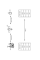
- FIG. 1 is a schematic diagram showing the overall configuration of a wireless communication system 10.
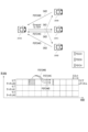
- FIG. 2 is a diagram illustrating the frequency ranges used in the wireless communication system 10.
- FIG. 3 is a diagram showing an example of the configuration of a radio frame, a subframe, and a slot used in the radio communication system 10.
- FIG. 4 is a functional block diagram of the UE 200.
- Figure 5 is a functional block diagram of gNB100.
- FIG. 6 is a functional block diagram of the LMF 300.
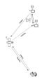
- FIG. 7 is a diagram for explaining the protocol in NTN.
- FIG. 8 is a diagram for explaining TA in NTN.
- FIG. 9 is a sequence diagram showing an operation example (1) of V2X.
- FIG. 10 is a sequence diagram showing an operation example (2) of V2X.
- FIG. 11 is a sequence diagram showing an operation example (3) of V2X.
- FIG. 12 is a sequence diagram showing an operation example (4) of V2X.
- FIG. 13 is a diagram showing an example of a sensing operation.
- FIG. 14 is a flowchart for explaining an example of a preemption operation.
- FIG. 15 is a diagram illustrating an example of a preemption operation.
- FIG. 16 is a diagram for explaining an example of periodic partial sensing.
- FIG. 17 is a diagram for explaining an example of continuous partial sensing.
- FIG. 18 is a diagram for explaining the operation example 2.
- FIG. FIG. 19 is a diagram for explaining the operation example 2.
- FIG. FIG. 20 is a diagram for explaining the operation example 2.
- FIG. 21 is a diagram for explaining the operation example 2.
- FIG. FIG. 22 is a diagram for explaining the operation example 2.
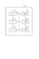
- FIG. 23 is a diagram showing an example of the hardware configuration of gNB100 and UE200.
- FIG. 24 is a diagram
- FIG. 1 is an overall schematic configuration diagram of a wireless communication system 10 according to an embodiment.
- the wireless communication system 10 is a wireless communication system conforming to 5G New Radio (NR) and includes a Next Generation-Radio Access Network 20 (hereinafter, NG-RAN 20) and a terminal 200 (hereinafter, UE (User Equipment) 200).
- NR 5G New Radio
- NG-RAN 20 Next Generation-Radio Access Network
- UE User Equipment
- the wireless communication system 10 may be a wireless communication system conforming to a method called Beyond 5G, 5G Evolution, or 6G.
- NG-RAN 20 includes a base station 100 (hereinafter, gNB 100).
- gNB 100 base station 100
- NG-RAN 20 actually includes multiple NG-RAN Nodes, specifically gNBs (or ng-eNBs), and is connected to a core network 30 conforming to 5G (e.g., 5GC).
- NG-RAN 20 and core network 30 may simply be referred to as a "network.”
- the gNB100 is a 5G-compliant radio base station, and performs 5G-compliant radio communication with the UE200.
- the gNB100 and UE200 are capable of supporting Massive MIMO (Multiple-Input Multiple-Output), which generates a more directional beam BM by controlling radio signals transmitted from multiple antenna elements, Carrier Aggregation (CA), which uses multiple component carriers (CC) by bundling them together, and Dual Connectivity (DC), which communicates simultaneously on two or more transport blocks between the UE and each of two NG-RAN Nodes.
- Massive MIMO Multiple-Input Multiple-Output
- CA Carrier Aggregation
- CC component carriers
- DC Dual Connectivity
- the core network 30 includes a network device 300.
- the network device 300 may include a Location Management Function (LMF).
- the network device 300 may include an Access and Mobility management Function (AMF).
- the network device 300 may be an Evolved Serving Mobile Location Centre (E-SMLC). The following mainly describes the case where the network device 300 is an LMF 300.
- LMF Location Management Function
- AMF Access and Mobility management Function
- E-SMLC Evolved Serving Mobile Location Centre
- a non-terrestrial network (hereinafter, NTN) may be assumed.
- NTN a non-terrestrial network such as an artificial satellite 150 (hereinafter, satellite 150) is used to provide services to areas that cannot be covered by a terrestrial network (hereinafter, TN) due to cost or other reasons.
- TN terrestrial network
- NTN can provide more reliable services.
- NTN is expected to be applied to IoT (Inter of things), ships, buses, trains, and critical communications.
- IoT Inter of things
- NTN also has scalability through efficient multicast or broadcast.
- a network that does not include a satellite 150 but includes a gNB 100 and a UE 200 may be referred to as a terrestrial network (TN) in contrast to an NTN.
- TN terrestrial network
- the gNB100 has an NTN gateway 100X.
- the NTN gateway 100X transmits a downlink signal to the satellite 150.
- the NTN gateway 100X receives an uplink signal from the satellite 150.
- the gNB100 has a cell C1 as its coverage area.
- Satellite 150 relays the downlink signal received from NTN gateway 100X to UE 200. Satellite 150 relays the uplink signal received from UE 200 to NTN gateway 100X. Satellite 150 has cell C2 as its coverage area. Satellite 150 may be considered to be a TRP (Transmission-Reception Point).
- TRP Transmission-Reception Point
- D2D (Device to Device) may be assumed in which UE200 (e.g., UE200A and UE200B) communicate directly with each other without going through gNB100.
- D2D may be referred to as sidelink or sidelink communication.
- D2D may include V2X (Vehicle to Everything) or eV2X (enhanced V2X).
- V2X is part of ITS (Intelligent Transport Systems) and may be a general term for V2V (Vehicle to Vehicle), which refers to a form of communication between vehicles, V2I (Vehicle to Infrastructure), which refers to a form of communication between a vehicle and a road-side unit (RSU: Road-Side Unit) installed on the side of the road, V2N (Vehicle to Network), which refers to a form of communication between a vehicle and an ITS server, and V2P (Vehicle to Pedestrian), which refers to a form of communication between a vehicle and a mobile terminal carried by a pedestrian.
- V2V Vehicle to Vehicle
- V2I Vehicle to Infrastructure
- RSU Road-Side Unit
- V2N Vehicle to Network
- V2P Vehicle to Pedestrian
- SL Sidelink
- UL Uplink
- DL Downlink
- SL may also be called something else.
- any of CP-OFDM Cyclic-Prefix OFDM
- DFT-S-OFDM Discrete Fourier Transform-Spread-OFDM
- OFDM without transform precoding
- OFDM with transform precoding any of CP-OFDM (Cyclic-Prefix OFDM), DFT-S-OFDM (Discrete Fourier Transform-Spread-OFDM), OFDM without transform precoding, or OFDM with transform precoding may be applied.
- the resource allocation method used in SL may include a first method in which resources are allocated by the gNB100, and a second method in which the UE200 autonomously selects resources.
- resources for SL communication may be allocated by downlink control information (DCI) transmitted from the gNB100 to the UE200.
- DCI downlink control information
- the first method may be referred to as Mode 1 resource allocation, and may be referred to as Mode 3 in LTE.
- the UE200 may select resources for SL communication from a resource pool (pre-configured resource pool).
- the second method may be referred to as Mode 2 resource allocation, and may be referred to as Mode 4 in LTE.
- the wireless communication system 10 supports multiple frequency ranges (FR).
- Figure 2 shows the frequency ranges used in the wireless communication system 10.
- the wireless communication system 10 supports FR1 and FR2.
- the frequency bands of each FR are as follows:
- FR1 may use a Sub-Carrier Spacing (SCS) of 15, 30 or 60 kHz and a bandwidth (BW) of 5 to 100 MHz.
- SCS Sub-Carrier Spacing
- BW bandwidth
- FR2 is a higher frequency than FR1, and may use a SCS of 60 or 120 kHz (including 240 kHz) and a bandwidth (BW) of 50 to 400 MHz.
- SCS may also be interpreted as numerology. Numerology is defined in 3GPP TS38.300 and corresponds to one subcarrier spacing in the frequency domain.
- the wireless communication system 10 also supports higher frequency bands than the FR2 frequency band. Specifically, the wireless communication system 10 supports frequency bands above 52.6 GHz up to 71 GHz or 114.25 GHz. For convenience, such higher frequency bands may be referred to as "FR2x.”
- Cyclic Prefix-Orthogonal Frequency Division Multiplexing CP-OFDM
- DFT-S-OFDM Discrete Fourier Transform - Spread
- SCS Sub-Carrier Spacing
- FIG. 3 shows an example of the configuration of a radio frame, subframe, and slot used in the wireless communication system 10.
- one slot is made up of 14 symbols, and the larger (wider) the SCS, the shorter the symbol period (and slot period).
- the SCS is not limited to the interval (frequency) shown in Figure 3. For example, 480 kHz, 960 kHz, etc. may be used.
- the number of symbols that make up one slot does not necessarily have to be 14 symbols (e.g., 28 symbols, 56 symbols). Furthermore, the number of slots per subframe may differ depending on the SCS.
- time direction (t) shown in FIG. 3 may be called the time domain, symbol period, or symbol time.
- the frequency direction may be called the frequency domain, resource block, subcarrier, bandwidth part (BWP), etc.
- DMRS is a type of reference signal and is prepared for various channels.
- DMRS may mean DMRS for a downlink data channel, specifically, PDSCH (Physical Downlink Shared Channel).
- DMRS for an uplink data channel specifically, PUSCH (Physical Uplink Shared Channel)
- PUSCH Physical Uplink Shared Channel
- DMRS may mean DMRS for a sidelink data channel, specifically, PSSCH (Physical Sidelink Shared Channel).
- PSSCH Physical Sidelink Shared Channel
- it may mean DMRS for a control channel.
- DMRS may be used for channel estimation in a device, e.g., UE 200, as part of coherent demodulation. DMRS may only be present in resource blocks (RBs) used for PDSCH transmission.
- RBs resource blocks
- DMRS may have multiple mapping types. Specifically, DMRS has mapping type A and mapping type B. In mapping type A, the first DMRS is placed in the second or third symbol of a slot. In mapping type A, the DMRS may be mapped relative to the slot boundary, regardless of where in the slot the actual data transmission starts. The reason for placing the first DMRS in the second or third symbol of a slot may be interpreted as being to place the first DMRS after the control resource sets (CORESET).
- CORESET control resource sets
- the first DMRS may be placed in the first symbol of the data allocation, i.e., the position of the DMRS may be given relative to where the data is placed, rather than relative to a slot boundary.
- DMRS may have multiple types. Specifically, DMRS has Type 1 and Type 2. Type 1 and Type 2 differ in mapping in the frequency domain and the maximum number of orthogonal reference signals. Type 1 is a single-symbol DMRS that can output up to four orthogonal signals, and Type 2 is a double-symbol DMRS that can output up to eight orthogonal signals.
- FIG. 4 is a functional block diagram of UE 200.
- UE 200 includes a radio signal transmitting/receiving unit 210, an amplifier unit 220, a modulation/demodulation unit 230, a control signal/reference signal processing unit 240, an encoding/decoding unit 250, a data transmitting/receiving unit 260, and a control unit 270.
- the radio signal transmission/reception unit 210 transmits and receives radio signals conforming to NR.
- the radio signal transmission/reception unit 210 supports Massive MIMO, CA that uses a bundle of multiple CCs, and DC that simultaneously communicates between a UE and each of two NG-RAN nodes.
- the amplifier section 220 is composed of a PA (Power Amplifier)/LNA (Low Noise Amplifier) etc.
- the amplifier section 220 amplifies the signal output from the modem section 230 to a predetermined power level.
- the amplifier section 220 also amplifies the RF signal output from the wireless signal transmission/reception section 210.
- the modem unit 230 performs data modulation/demodulation, transmission power setting, resource block allocation, etc. for each predetermined communication destination (gNB100 or another gNB or another UE200).
- the modem unit 230 may apply Cyclic Prefix-Orthogonal Frequency Division Multiplexing (CP-OFDM)/Discrete Fourier Transform-Spread (DFT-S-OFDM).
- CP-OFDM Cyclic Prefix-Orthogonal Frequency Division Multiplexing
- DFT-S-OFDM Discrete Fourier Transform-Spread
- DFT-S-OFDM may be used not only for the uplink (UL) but also for the downlink (DL) or sidelink (SL).
- the control signal/reference signal processing unit 240 performs processing related to various control signals transmitted and received by the UE 200, and processing related to various reference signals transmitted and received by the UE 200.
- control signal/reference signal processor 240 receives various control signals, such as radio resource control layer (RRC) control signals, transmitted from the gNB100 or other UEs 200 via a predetermined control channel.
- RRC radio resource control layer
- the control signal/reference signal processor 240 also transmits various control signals to the gNB100 or other UEs 200 via a predetermined control channel.
- the control signal/reference signal processing unit 240 performs processing using reference signals (RS) such as the Demodulation Reference Signal (DMRS) and the Phase Tracking Reference Signal (PTRS).
- RS reference signals
- DMRS Demodulation Reference Signal
- PTRS Phase Tracking Reference Signal
- DMRS is a known reference signal (pilot signal) between the base station and the terminal for each terminal, used to estimate the fading channel used for data demodulation.
- PTRS is a terminal-specific reference signal intended to estimate phase noise, which is an issue in high frequency bands.
- reference signals may also include Channel State Information-Reference Signal (CSI-RS), Sounding Reference Signal (SRS), and Positioning Reference Signal (PRS) for location information.
- CSI-RS Channel State Information-Reference Signal
- SRS Sounding Reference Signal
- PRS Positioning Reference Signal
- Control channels include control channels and data channels.
- Control channels include PDCCH (Physical Downlink Control Channel), PUCCH (Physical Uplink Control Channel), RACH (Random Access Channel), Downlink Control Information (DCI) including Random Access Radio Network Temporary Identifier (RA-RNTI), and Physical Broadcast Channel (PBCH).
- Control channels in the sidelink include PSCCH (Physical Sidelink Control Channel), PSDCH (Physical Sidelink Discovery Channel), PSBCH (Physical Sidelink Broadcast Channel), and PSFCH (Physical Sidelink Feedback Channel).
- data channels include PDSCH (Physical Downlink Shared Channel) and PUSCH (Physical Uplink Shared Channel).
- Data means data transmitted via a data channel.
- Data channel may be interpreted as a shared channel.
- data channels in the sidelink include PSSCH (Physical Sidelink Shared Channel), etc.
- the control signal/reference signal processing unit 240 may receive downlink control information (DCI).
- DCI includes fields that store existing fields such as DCI Formats, Carrier indicator (CI), BWP indicator, FDRA (Frequency Domain Resource Assignment), TDRA (Time Domain Resource Assignment), MCS (Modulation and Coding Scheme), HPN (HARQ Process Number), NDI (New Data Indicator), and RV (Redundancy Version).
- CI Carrier indicator
- BWP indicator BWP indicator
- FDRA Frequency Domain Resource Assignment
- TDRA Time Domain Resource Assignment
- MCS Modulation and Coding Scheme
- HPN HARQ Process Number
- NDI New Data Indicator
- RV Redundancy Version
- the value stored in the DCI Format field is an information element that specifies the format of the DCI.
- the value stored in the CI field is an information element that specifies the CC to which the DCI applies.
- the value stored in the BWP indicator field is an information element that specifies the BWP to which the DCI applies.
- the BWP that can be specified by the BWP indicator is set by an information element (BandwidthPart-Config) included in the RRC message.
- the value stored in the FDRA field is an information element that specifies the frequency domain resource to which the DCI applies.
- the frequency domain resource is identified by the value stored in the FDRA field and an information element (RA Type) included in the RRC message.
- the value stored in the TDRA field is an information element that specifies the time domain resource to which the DCI applies.
- the time domain resource is identified by the value stored in the TDRA field and an information element (pdsch-TimeDomainAllocationList, pusch-TimeDomainAllocationList) included in the RRC message.
- the time domain resource may be identified by the value stored in the TDRA field and a default table.
- the value stored in the MCS field is an information element that specifies the MCS to which the DCI applies.
- the MCS is specified by the value stored in the MCS and the MCS table.
- the MCS table may be specified by an RRC message or may be specified by RNTI scrambling.
- the value stored in the HPN field is an information element that specifies the HARQ Process to which the DCI is applied.
- the value stored in the NDI is an information element that specifies whether the data to which the DCI is applied is initial transmission data or not.
- the value stored in the RV field is an information element that specifies the redundancy of the data to which the DCI is applied.
- the encoding/decoding unit 250 performs data division/concatenation and channel coding/decoding for each predetermined communication destination (gNB100 or another gNB or another UE200).
- the encoding/decoding unit 250 divides the data output from the data transmission/reception unit 260 into pieces of a predetermined size, and performs channel coding on the divided data.
- the encoding/decoding unit 250 also decodes the data output from the modem unit 230, and concatenates the decoded data.
- the data transmission/reception unit 260 transmits and receives Protocol Data Units (PDUs) and Service Data Units (SDUs). Specifically, the data transmission/reception unit 260 performs assembly/disassembly of PDUs/SDUs in multiple layers (such as the Medium Access Control layer (MAC), Radio Link Control layer (RLC), and Packet Data Convergence Protocol layer (PDCP)). The data transmission/reception unit 260 also performs data error correction and retransmission control based on HARQ (Hybrid Automatic Repeat Request).
- MAC Medium Access Control layer
- RLC Radio Link Control layer
- PDCP Packet Data Convergence Protocol layer
- the data transmission/reception unit 260 also performs data error correction and retransmission control based on HARQ (Hybrid Automatic Repeat Request).
- HARQ Hybrid Automatic Repeat Request
- the control unit 270 controls each functional block constituting the UE 200.
- the control unit 270 may control UL communication or SL communication.
- UL communication is an example of communication at an interface (Uu interface) between the gNB 100 and the UE 200.
- SL communication is an example of communication at an interface (PC5 interface) between UEs 200 and UEs 200.
- FIG. 5 is a functional block diagram of the gNB100. As shown in FIG. 5, the gNB100 has a receiving unit 110, a transmitting unit 120, and a control unit 130.
- the receiving unit 110 receives various signals from the UE 200.
- the receiving unit 110 may receive a UL signal via a PUCCH or a PUSCH.
- the transmitter 120 transmits various signals to the UE 200.
- the transmitter 120 may transmit DL signals via the PDCCH or PDSCH.
- the control unit 130 controls the gNB 100.
- the control unit 130 may assume that the UE 200 performs the SL communication.
- FIG. 6 is a functional block diagram of the LMF 300. As shown in FIG. 6, the LMF 300 has a receiving unit 310, a transmitting unit 320, and a control unit 330.
- the receiving unit 310 may receive various messages from the UE 200.
- the message may be referred to as an LPP Provide Location Information or as an NRPPa (NR Positioning Protocol A) message (Type: Measurement Report).
- the receiving unit 310 may receive various messages from the gNB 100.
- the message may be referred to as an NRPPa message (Type: POSITIONING INFORMATION REQUEST).
- the transmitting unit 320 may transmit various messages to the UE 200.
- the messages may be referred to as LPP Provide Assistance Data.
- the transmitting unit 320 may transmit various messages to the gNB 100.
- the messages may be referred to as NRPPa messages (Type: Measurement Request).
- the control unit 330 controls the LMF 300.
- the control unit 330 may perform specific control (Multi-RTT Positioning) to estimate location information of the UE 200 based on the UE Rx-Tx time difference.
- the control unit 330 may perform specific control (DL-TDOA Positioning) to estimate location information of the UE 200 based on the DL RSTD (Reference Signal Time Difference).
- gNB100 has a protocol stack including PHY, MAC, RLC, PDCP, and RRC/SDAP.
- UE200 has a protocol stack including PHY, MAC, RLC, PDCP, and RRC/SDAP. Satellite150 relays communication between gNB100 and UE200.
- the link between the gNB100 (NTN Gateway 100X) and the satellite 150 may be referred to as a Feeder link.
- the link between the satellite 150 and the UE 200 may be referred to as a Service link.
- the interface between the gNB100 and the UE 200 may be referred to as an NR Uu.
- NTN's network architecture may be FDD or TDD.
- the terrestrial cells may be fixed or mobile.
- UE200 may have the capability to support GNSS (Global Navigation Satellite System).
- UE200 may be a power class 3 handheld device in FR1, and may be a VSAT (Very small aperture terminal) at least in FR2.
- GNSS Global Navigation Satellite System
- VSAT Very small aperture terminal
- NTN's network architecture may envision regenerative payloads.
- the gNB100 functionality may be mounted on a satellite or an aircraft.
- a gNB-DU distributed Unit
- a gNB-CU Central Unit
- the TA of the feeder link is a value corresponding to the round trip delay (RTT) of the feeder link, and can be expressed as 2 ⁇ (User transparent + N TA,common ).
- User transparent is a value that is transparent to the UE 200 and is compensated by the network (gNB 100). To simplify the implementation of the gNB 100, the value of User transparent may be a constant.
- N TA,common is a TA common to the beams or cells of the satellite 150. N TA,common is set based on the RP (Reference Point).
- the TA of the service link is a value corresponding to the round trip delay (RTT) of the service link, and can be expressed by 2 ⁇ N TA,UE-specific , where N TA,UE-specific is a value specific to the UE 200.
- TA may be expressed by the formula shown below.
- T TA (N TA +N TA,UE-specific +N TA,common +N TA,offset ) ⁇ Tc
- T TA Timing advance between downlink and uplink
- N TA Timing advance between downlink and uplink
- N TA,UE-specific UE-derived timing correction
- N TA, common Network-controlled timing correction
- N TA,offset A fixed offset used to calculate the timing advance
- Tc Basic time unit for NR N TA is a closed loop TA.
- N TA is defined as 0 in the Physical Random Access Channel (PRACH).
- PRACH Physical Random Access Channel
- N TA is updated based on the TA Command field of msg2/msgB and the TA command of the Medium Access Control Element (MAC CE).
- MAC CE Medium Access Control Control Element
- N TA,UE-specific is an open-loop TA.
- N TA,UE-specific is a TA for compensating for delay in a service link, and is autonomously updated by the UE 200.
- N TA,UE-specific is calculated based on the location information of the UE 200 and the orbit information of the satellite 150. For example, the location information of the UE 200 may be acquired based on a radio signal from a satellite positioning system (not shown).
- N TA,common is an open-loop TA.
- N TA,common is a common TA controlled by the network (gNB100).
- N TA,common is autonomously updated by UE200 using parameters (parameters for determining the common TA) notified by gNB100.
- a reference point (RP) that defines N TA,common may be set anywhere on the feeder link.
- the RP may be set to the gNB 100, may be set to the satellite 150, or may be set between the gNB 100 and the satellite 150.
- the burden on the gNB 100 is reduced.
- the RP is set to the satellite 150, there is an advantage that N TA,common becomes 0, and the burden on the UE 200 is reduced.
- the UE200 performing SL communication may be a vehicle, a terminal held by a person, the communication device may be a device mounted on a drone or an aircraft, the communication device may be a base station, an RSU, a relay station (relay node), a terminal with scheduling capability, or an IoT (Internet of Things) device such as a smart meter.
- the communication device may be a device mounted on a drone or an aircraft, the communication device may be a base station, an RSU, a relay station (relay node), a terminal with scheduling capability, or an IoT (Internet of Things) device such as a smart meter.
- IoT Internet of Things
- the term "configuring" radio parameters, etc. may mean that predetermined values are pre-configured, or that radio parameters notified from the gNB100 or UE200 are configured.
- HARQ Hybrid automatic repeat request
- SFCI Segmentlink Feedback Control Information
- PSFCH Physical Sidelink Feedback Channel
- the PSFCH is used for transmitting and receiving the HARQ-ACK on the sidelink, but this is just one example.
- the HARQ-ACK may be transmitted on the sidelink using the PSCCH, the HARQ-ACK may be transmitted on the sidelink using the PSSCH, or another channel may be used to transmit the HARQ-ACK on the sidelink.
- HARQ-ACK information reported by UE200 in HARQ
- This HARQ-ACK may also be referred to as HARQ-ACK information.
- a codebook applied to HARQ-ACK information reported from UE200 to gNB100, etc. is referred to as a HARQ-ACK codebook.
- the HARQ-ACK codebook specifies the bit sequence of the HARQ-ACK information.
- NACK is also transmitted using "HARQ-ACK".
- FIG. 9 is a sequence diagram showing an example of V2X operation (1).
- a wireless communication system according to an embodiment of the present invention may have UE200A and UE200B. Note that, although there are actually many user devices, FIG. 9 shows UE200A and UE200B as an example.
- UE200A when there is no particular distinction between UE200A, UE200B, etc., they will be simply referred to as “UE200” or "user equipment.”
- UE200 user equipment
- FIG. 9 as an example, a case where UE200A and UE200B are both within the coverage of a cell is shown, but the operation in the embodiment of the present invention can also be applied to a case where UE200B is outside the coverage.
- UE200 does not need to be a device in a single housing.
- the device including the various sensors may be UE200.
- UE200 scrambles and modulates the codeword of the transmission data to generate complex-valued symbols, maps the complex-valued symbols (transmission signal) to one or two layers, and performs precoding. Then, it maps the precoded complex-valued symbols to resource elements to generate a transmission signal (e.g., a complex-valued time-domain SC-FDMA signal), which is then transmitted from each antenna port.
- a transmission signal e.g., a complex-valued time-domain SC-FDMA signal
- the gNB100 has a cellular communication function as a base station in LTE or NR, and a function for enabling communication of the UE200 in this embodiment (e.g., resource pool setting, resource allocation, etc.).
- the gNB100 may also be an RSU (gNB type RSU).
- the signal waveform used by UE200 for SL or UL may be OFDMA, SC-FDMA, or another signal waveform.
- S-SSB may include Sidelink Primary Synchronization Signal (S-PSS), Sidelink Secondary Synchronization Signal (S-SSS), and Physical Sidelink Broadcast Channel (PSBCH).
- S-PSS Sidelink Primary Synchronization Signal
- S-SSS Sidelink Secondary Synchronization Signal
- PSBCH Physical Sidelink Broadcast Channel
- UE200 transmits an S-SSB to another UE200 based on a signal received from a gNB100, a Global Navigation Satellite System (GNSS) signal, or a signal received from another UE200. If the UE200 cannot transmit an S-SSB based on any signal from the gNB100, the GNSS, or another UE200, the UE200 may transmit an autonomously determined S-SSB to the other UE200.
- the resources available for the S-SSB may be periodic slots and may be referred to as S-SSB opportunities.
- UE200A autonomously selects resources to be used for PSCCH and PSSCH from a resource selection window having a predetermined period.
- the resource selection window may be set in UE200 from gNB100.
- the predetermined period of the resource selection window may be determined by the implementation conditions of the terminal, such as the processing time or maximum allowable packet delay time, or may be determined in advance by specifications, or the predetermined period may be referred to as an interval in the time domain.
- UE200A transmits SCI (Sidelink Control Information) via PSCCH and/or PSSCH using the resources autonomously selected in step S101, and transmits SL data via PSSCH.
- SCI Segment Control Information
- UE200A may transmit PSCCH using frequency resources that are adjacent or non-adjacent to the frequency resources of PSSCH, with time resources that are the same as at least a portion of the time resources of PSSCH.
- UE200B receives the SCI (PSCCH and/or PSSCH) and SL data (PSSCH) transmitted from UE200A.
- the received SCI may include information on the PSFCH resource for UE200B to transmit a HARQ-ACK in response to the reception of the data.
- UE200A may transmit the SCI including information on the autonomously selected resource.
- the resources available for the PSFCH may be periodic slots and the last symbols in the slot (excluding the final symbol), and may be called PSFCH opportunities.
- step S104 UE200B transmits a HARQ-ACK for the received data to UE200A using the PSFCH resources determined from the received SCI.
- step S105 if the HARQ-ACK received in step S104 indicates a request for retransmission, i.e., if the HARQ-ACK is a NACK (negative acknowledgement), UE 200A retransmits the PSCCH and PSSCH to UE 200B. UE 200A may retransmit the PSCCH and PSSCH using autonomously selected resources.
- steps S104 and S105 do not need to be performed.
- FIG. 10 is a sequence diagram showing an example of V2X operation (2). Blind retransmission without HARQ control may be performed to improve the transmission success rate or reach.
- step S201 UE200A autonomously selects resources to be used for PSCCH and PSSCH from a resource selection window having a predetermined period.
- the resource selection window may be set to UE200 by gNB100.
- UE200A transmits SCI via PSCCH and/or PSSCH using the resources autonomously selected in step S201, and transmits SL data via PSSCH.
- UE200A may transmit PSCCH using time resources that are the same as at least a portion of the time resources of PSSCH and frequency resources adjacent to the frequency resources of PSSCH.
- step S204 UE200A retransmits the SCI via PSCCH and/or PSSCH and the SL data via PSSCH to UE200B using the resources autonomously selected in step S201.
- the retransmission in step S204 may be performed multiple times.
- step S204 does not need to be performed.
- FIG. 11 is a sequence diagram showing an example of V2X operation (3).
- the gNB100 may perform sidelink scheduling. That is, the gNB100 may determine the sidelink resources to be used by the UE200 and transmit information indicating the resources to the UE200. Furthermore, when HARQ control involving HARQ feedback is applied, the gNB100 may transmit information indicating the PSFCH resources to the UE200.
- step S301 gNB100 performs SL scheduling by sending DCI (Downlink Control Information) to UE200A via the PDCCH.
- DCI Downlink Control Information
- SL scheduling DCI DCI for SL scheduling
- step S301 it is assumed that gNB100 also transmits DCI for DL scheduling (which may also be called DL allocation) to UE200A via PDCCH.
- DCI for DL scheduling is called DL scheduling DCI.
- UE200A that receives DL scheduling DCI receives DL data via PDSCH using resources specified in the DL scheduling DCI.
- UE200A transmits SCI (Sidelink Control Information) via PSCCH and/or PSSCH using resources specified in the SL scheduling DCI, and transmits SL data via PSSCH.
- SCI Servicelink Control Information
- PSSCH Physical Broadcast Control Information
- UE200A may transmit PSCCH using frequency resources adjacent to the frequency resources of PSSCH with time resources that are the same as at least a portion of the time resources of PSSCH.
- UE200B receives the SCI (PSCCH and/or PSSCH) and SL data (PSSCH) transmitted from UE200A.
- the SCI received via the PSCCH and/or PSSCH includes information on the PSFCH resource for UE200B to transmit a HARQ-ACK in response to the reception of the data.
- the information on the resource is included in the DL scheduling DCI or SL scheduling DCI transmitted from the gNB100 in step S301, and the UE200A obtains the information on the resource from the DL scheduling DCI or SL scheduling DCI and includes it in the SCI.
- the DCI transmitted from the gNB100 may not include the information on the resource, and the UE200A may autonomously include the information on the resource in the SCI and transmit it.
- step S304 UE200B transmits a HARQ-ACK for the received data to UE200A using the PSFCH resources determined from the received SCI.
- UE200A transmits a HARQ-ACK using PUCCH (Physical uplink control channel) resources specified by the DL scheduling DCI (or the SL scheduling DCI) at a timing (e.g., slot-by-slot timing) specified by the DL scheduling DCI (or the SL scheduling DCI), and gNB100 receives the HARQ-ACK.
- the codebook for the HARQ-ACK may include a HARQ-ACK generated based on the HARQ-ACK received from UE200B or a PSFCH that was not received, and a HARQ-ACK for DL data. However, if no DL data is assigned, for example, a HARQ-ACK for DL data is not included. In NR Rel. 16, the codebook for the HARQ-ACK does not include a HARQ-ACK for DL data.
- step S304 and/or step S305 may not be performed.
- FIG. 12 is a sequence diagram showing an example of V2X operation (4).
- the PSFCH format can be, for example, the same format as PUCCH (Physical Uplink Control Channel) format 0. That is, the PSFCH format may be a sequence-based format in which the PRB (Physical Resource Block) size is 1 and ACK and NACK are identified by differences in sequence and/or cyclic shift.
- the PSFCH format is not limited to this.
- the PSFCH resource may be placed in the last symbol or the last multiple symbols of the slot.
- a period N is set or predefined for the PSFCH resource. The period N may be set or predefined on a slot-by-slot basis.
- the vertical axis corresponds to the frequency domain
- the horizontal axis corresponds to the time domain.
- the PSCCH may be placed in one symbol at the beginning of the slot, or in multiple symbols from the beginning, or in multiple symbols from a symbol other than the beginning.
- the PSFCH may be placed in one symbol at the end of the slot, or in multiple symbols at the end of the slot. Note that the above-mentioned "beginning of the slot” and "end of the slot” may omit consideration of symbols for AGC (Automatic Gain Control) and symbols for transmission/reception switching.
- AGC Automatic Gain Control
- the "beginning of the slot” and “end of the slot” may mean the first and last symbols, respectively, of the 12 symbols excluding the first and last symbols.
- three subchannels are set in the resource pool, and two PSFCHs are placed three slots after the slot in which the PSSCH is placed.
- the arrow from the PSSCH to the PSFCH shows an example of a PSFCH associated with the PSSCH.
- step S401 UE200A, which is the transmitting UE200, performs groupcast to UE200B, UE200C, and UE200D, which are receiving UE200, via SL-SCH (Sidelink Shared Channel).
- step S402 UE200B uses PSFCH#B, UE200C uses PSFCH#C, and UE200D uses PSFCH#D to transmit the HARQ response to UE200A.
- UE200B uses PSFCH#B
- UE200C uses PSFCH#C
- UE200D uses PSFCH#D to transmit the HARQ response to UE200A.
- the transmitting UE200 may know the number of receiving UE200 in the groupcast.
- groupcast option 1 only NACK is sent as a HARQ response, and ACK is not sent.
- Figure 13 shows an example of sensing operation in NR.
- UE 200 selects a resource and transmits.
- UE 200 performs sensing in a sensing window in a resource pool.
- UE 200 receives a resource reservation field or a resource assignment field included in an SCI transmitted from another UE 200, and identifies available resource candidates in a resource selection window in the resource pool based on the field.
- UE 200 then randomly selects a resource from the available resource candidates.
- the resource pool may be set to have a period.
- the period may be a period of 10240 milliseconds.
- Fig. 13 shows an example in which slot t0SL to slot tTmax -1SL are set as a resource pool.
- the resource pool in each period may have an area set by, for example, a bitmap.
- a transmission trigger in UE 200 occurs in slot n, and the priority of the transmission is p TX .
- UE 200 can detect, for example, that another UE 200 is transmitting with priority p RX in a sensing window from slot nT 0 to the slot immediately before slot nT proc,0 .
- RSRP Reference Signal Received Power
- a resource in a resource selection window corresponding to the SCI is excluded.
- RSRP Reference Signal Received Power
- a resource in a resource selection window corresponding to the SCI is not excluded.
- the threshold may be, for example, a threshold Th pTX,pRX that is set or defined for each resource in the sensing window based on the priority p TX and the priority p RX .
- resources in the resource selection window that are candidates for resource reservation information corresponding to resources in the sensing window that were not monitored for transmission such as slot t m SL shown in FIG. 13, are excluded.
- the threshold Th pTX,pRX set for each resource of the sensing window may be increased by 3 dB and resource identification may be performed again. That is, by increasing the threshold Th pTX,pRX and performing resource identification again, the number of resources that are not excluded because the RSRP is less than the threshold may be increased so that the set of resource candidates S A becomes 20% or more of the resource selection window.
- the operation of increasing the threshold Th pTX,pRX set for each resource of the sensing window by 3 dB and performing resource identification again may be repeated.
- a lower layer of the UE 200 may report the S A to a higher layer.
- the higher layer of the UE 200 may perform random selection on the S A to determine a resource to be used.
- the UE 200 may perform sidelink transmission using the determined resource.
- the higher layer may be a MAC layer
- the lower layer may be a PHY layer or a physical layer.
- the operation of the transmitting UE 200 is described, but the receiving UE 200 may detect data transmission from another UE 200 based on the results of sensing or partial sensing, and receive data from the other UE 200.
- FIG. 14 is a flowchart showing an example of preemption in NR.
- FIG. 15 is a diagram showing an example of preemption in NR.
- UE 200 performs sensing in a sensing window. When UE 200 performs a power saving operation, sensing may be performed in a predefined limited period.
- UE 200 identifies each resource in the resource selection window based on the sensing result to determine a set S A of resource candidates, and selects resources to be used for transmission (S502).
- UE 200 selects a resource set (r_0, r_1, ...) for determining preemption from the set S A of resource candidates (S503).
- the resource set may be notified to the PHY layer from the upper layer as a resource for determining whether or not preemption has been performed.
- step S504 the UE 200 re-identifies each resource in the resource selection window based on the sensing result at the timing T(r_0)-T3 shown in FIG. 15 to determine a set S A of resource candidates, and further determines preemption for the resource set (r_0, r_1, ...) based on the priority.
- r_1 shown in FIG. 15 is not included in S A because the SCI transmitted from the other UE 200 is detected by re-sensing.
- the UE 200 determines that the resource r_1 has been preempted. Note that the lower the value indicating the priority, the higher the priority. That is, when the value prio_RX indicating the priority of the SCI transmitted from the other UE 200 is higher than the value prio_TX indicating the priority of the transport block transmitted from the own terminal, the UE 200 does not exclude the resource r_1 from the SA .
- sl-PreemptionEnable is any of pl1, pl2, ..., pl8
- this priority is set as prio_pre.
- prio_RX indicating the priority of the SCI transmitted from the other UE 200
- prio_RX is lower than the value prio_TX indicating the priority of the transport block transmitted from the own terminal
- step S505 if preemption is determined in step S504, UE200 notifies the upper layer of preemption, reselects resources in the upper layer, and ends the preemption check.
- step S504 when performing re-evaluation instead of checking preemption, after determining the set S A of resource candidates in step S504, if a resource in the resource set (r_0, r_1, ...) is not included in S A , the resource is not used and a resource re-selection is performed in the upper layer.
- a UE 200 to which partial sensing is applied performs reception and sensing only in specific slots within a sensing window. That is, the UE 200 may perform resource identification by sensing only limited resources compared to full sensing, and perform partial sensing to select resources from the identified resource set. The UE 200 may also perform random selection to select resources from the identified resource set by setting the resources in the resource selection window as the identified resource set without excluding resources from the resources in the resource selection window.
- the method of performing random selection at the time of resource selection and using sensing information during reevaluation or preemption checks may be treated as partial sensing or as random selection.
- sensing operations may be 1) and 2) shown below. Note that sensing and monitoring may be interchangeable, and the sensing operations may include at least one of measuring the received RSRP, obtaining reservation resource information, and obtaining priority information.
- Periodic-based partial sensing In a mechanism in which sensing is performed only on some slots, an operation of determining a sensing slot based on a reservation periodicity.
- the reservation period is a value related to a resource reservation period field. Note that the period may be replaced with periodicity.
- SL-DRX discontinuous reception
- reception operations are only performed during a specified time period.
- partial sensing is supported as one of the power saving functions.
- UE200 may execute the above-mentioned periodic partial sensing.
- UE200 may receive information from gNB100 for configuring a resource pool in which partial sensing is configured and periodic reservation is enabled.
- FIG 16 is a diagram for explaining an example of periodic partial sensing. As shown in FIG 16, Y candidate slots for resource selection are selected from a resource selection window [n+ T1 , n+ T2 ].
- Sensing may be performed by treating t y SL as one slot included in the Y candidate slots and treating t yk ⁇ Preserve SL as a target slot for periodic partial sensing.
- P reserve may correspond to all values included in a set or predefined set sl-ResouceReservePeriodList.
- values of P reserve limited to a subset of sl-ResouceReservePeriodList may be set or predefined.
- P reserve and sl-ResouceReservePeriodList may be set for each transmission resource pool of resource allocation mode 2.
- a period included in sl-ResouceReservePeriodList other than the limited subset may be monitored.
- UE 200 may additionally monitor an opportunity corresponding to P_RSVP_Tx.
- UE200 may monitor the newest sensing opportunity in a certain reservation period before slot n of the resource selection trigger or before the first slot of Y candidate slots that are subject to processing time restrictions. UE200 may also additionally monitor periodic sensing opportunities corresponding to a set of one or more k values. For example, the k value may be set to a value corresponding to the newest sensing opportunity in a certain reservation period before slot n of the resource selection trigger or before the first slot of Y candidate slots that are subject to processing time restrictions, and a value corresponding to the sensing opportunity immediately prior to the newest sensing opportunity in the certain reservation period.
- partial sensing is supported as one of the power saving functions.
- UE200 may execute the above-mentioned continuous partial sensing.
- UE200 may receive information from gNB100 for configuring a resource pool in which partial sensing is configured and non-periodic reservation is enabled.
- Fig. 17 is a diagram for explaining an example of continuous partial sensing.
- UE200 selects Y candidate slots for resource selection from the resource selection window [n+ T1 , n+ T2 ].
- the beginning of the Y candidate slots is represented as slot t y1
- the next slot is represented as slot t y2
- ... the end of the Y candidate slots is represented as slot t yY .
- UE200 performs sensing in the interval [n+T A , n+T B ], and performs resource selection in n+T B or after n+T B (n+T C ).
- the above-mentioned periodic partial sensing may be additionally performed.
- T A and T B in the interval [n+T A , n+T B ] may be any value.
- n may be replaced with an index of any slot among Y candidate slots.
- the interval [a, b] is the interval from slot a to slot b, including slot a and slot b.
- the interval (a, b) is the interval from slot a to slot b, excluding slot a and slot b.
- the candidate resources to be selected are referred to as Y candidate slots, but all slots in the interval [n+T 1 , n+T 2 ] may be candidate slots, or only some of the slots may be candidate slots.
- inter-terminal coordination has been specified as a method for improving reliability and delay performance.
- the inter-terminal coordination method 1 and inter-terminal coordination method 2 shown below have been specified.
- the UE 200 that transmits coordination information will be referred to as UE-A
- the UE 200 that receives the coordination information will be referred to as UE-B.
- Inter-UE coordination method 1 For UE-B transmission, a preferred resource set and/or a non-preferred resource set are transmitted from UE-A to UE-B.
- inter-UE coordination method 1 is also referred to as IUC scheme 1 (Inter-UE coordination scheme 1).
- Inter-UE coordination method 2 UE-A transmits to UE-B information indicating resources in which a collision with other transmissions or receptions is expected and/or a collision has been detected, among resources indicated by the SCI received from UE-B.
- the information may be transmitted via the PSFCH.
- inter-UE coordination method 2 is also referred to as IUC scheme 2 (Inter-UE coordination scheme 2).
- SL communication may also be applied to unlicensed bands, such as the 5GHz-7GHz band and the 60GHz band.
- NTN Cell NTN Cell
- TN Cell TN Cell
- UE200 has a receiving unit (e.g., radio signal transmitting/receiving unit 210) that receives first information that identifies the target cell as a specific cell (NTN Cell) belonging to a non-terrestrial network and second information that identifies that the target cell supports side link communication (SL communication).
- gNB100 has a transmitting unit (e.g., transmitting unit 120) that transmits the first information that identifies that the target cell is a specific cell (NTN Cell) belonging to a non-terrestrial network and second information that identifies that the target cell supports side link communication (SL communication).
- the target cell may be interpreted as a certain cell, or as a cell from which UE200 can receive a notification signal (MIB/SIB/SSB, etc.).
- the first information may be at least one of broadcast information (SIB1) including information indicating that the target cell is an NTN Cell and broadcast information (NTN-specific SIB) including parameters used in the NTN Cell.
- SIB1 broadcast information
- NTN-specific SIB broadcast information
- SIB19 broadcast information
- the second information may be notification information (SL-specific SIB) including parameters used in SL communication.
- SL-specific SIB may be referred to as SIB12.
- the first information and the second information may be separate pieces of notification information. It should be noted that in existing technology, an operation based on the first information and an operation based on the second information are assumed to be separate operations, and an operation based on both the first information and the second information is not assumed.
- UE200 has a control unit (e.g., control unit 270) that executes specific control regarding sidelink communication based on the first information and the second information.
- gNB100 has a control unit (e.g., control unit 130) that assumes that UE200 controls specific control regarding sidelink communication based on the first information and the second information.
- the specific control related to operation example 1 may be referred to as the first specific control.
- a UE200 capable of performing SL communication based on an NTN Cell may perform Uu communication with the NTN Cell based on an NTN-specific SIB, and may perform SL communication based on a SL-specific SIB.
- Mode 1 resource allocation (first method) or Mode 2 resource allocation (second method) may be assumed for SL communication.
- SL communication can be carried out under the control of the NTN Cell in an NTN Cell with a wide coverage area.
- UE200 may connect to the NTN Cell and transmit information (hereinafter, first capability information) indicating whether or not SL communication is to be performed based on the SL-specific SIB.
- UE200 may connect to the NTN Cell and transmit information (hereinafter, second capability information) indicating whether or not operation related to simultaneous execution of communication between the NTN Cell and UE200 (Uu communication) and SL communication based on the SL-specific SIB is possible.
- UE200 may transmit both the first capability information and the second capability information.
- the first capability information and the second capability information may be examples of UE Capability.
- Mode 1 resource allocation (first method) or Mode 2 resource allocation (second method) may be assumed as SL communication.
- simultaneous execution may mean performing SL communication while connected to the NTN Cell (RRC Connected). Therefore, assuming a case in which UE200 operates in half-duplex, simultaneous execution does not have to mean performing Uu communication and SL communication at overlapping times. Alternatively, simultaneous execution may mean performing Uu communication and SL communication at overlapping times.
- Option 1-2 allows the operation of the NW (NTN Cell) to be appropriately determined for the UE 200 that wishes to perform SL communication.
- UE200 may receive information indicating whether UE200 performing SL communication based on the SL-specific SIB can connect to the NTN Cell.
- UE200 may perform SL communication based on the SL-specific SIB in addition to communication between the NTN Cell and UE200 (Uu communication).
- UE200 may perform either communication between the NTN Cell and UE200 (Uu communication) or SL communication based on the SL-specific SIB.
- Mode 1 resource allocation (first method) or Mode 2 resource allocation (second method) may be assumed as the SL communication.
- Options 1-3 make it possible to properly execute SL communication assuming NTN in a case where the gNB100 does not support operations related to the simultaneous execution of communication between the NTN Cell and UE200 (Uu communication) and SL communication based on the SL-specific SIB.
- UE200 that does not support the simultaneous execution of communication between the NTN Cell and UE200 (Uu communication) and SL communication based on a SL-specific SIB may receive information indicating whether or not it can connect to the NTN Cell.
- UE200 may execute SL communication based on the SL-specific SIB in addition to communication between the NTN Cell and UE200 (Uu communication).
- UE200 may execute either communication between the NTN Cell and UE200 (Uu communication) or SL communication based on the SL-specific SIB.
- Mode 1 resource allocation (first method) or Mode 2 resource allocation (second method) may be assumed as the SL communication.
- Options 1-4 make it possible to avoid a situation in which a UE200 that does not support quality improvement operations related to the simultaneous execution of communication between the NTN Cell and UE200 (Uu communication) and SL communication based on the SL-specific SIB connects to the NTN Cell.
- Options 1-5 describe SL communication between a UE200 performing SL communication based on an NTN Cell and a UE200 performing SL communication not based on an NTN Cell.
- the SL communication based on an NTN Cell may be Mode 1 resource allocation (first method) or Mode 2 resource allocation (second method) based on parameters set via the NTN Cell.
- the SL communication not based on an NTN Cell may be Mode 1 resource allocation (first method) or Mode 2 resource allocation (second method) based on parameters that are not parameters set via the NTN Cell (e.g. parameters set via a TN Cell, pre-configured parameters).
- a UE200 performing SL communication based on an NTN Cell may perform the operations shown below.
- UE200 may perform SL communication using SL communication resources that are not based on NTN Cell (e.g., a pre-configuration resource pool).
- NTN Cell e.g., a pre-configuration resource pool
- UE200 may transmit SL communication without receiving SL communication.
- UE200 may receive SL communication without transmitting SL communication.
- UE200 may both transmit and receive SL communication.
- UE200 may simultaneously perform SL communication based on NTN Cell and SL communication not based on NTN Cell. In such a case, UE200 may prioritize one of the SL communications when the SL communication based on NTN Cell and the SL communication not based on NTN Cell overlap in time. For example, SL communication based on NTN Cell may be prioritized over SL communication not based on NTN Cell.
- UE200 may switch between SL communication based on NTN Cell and SL communication not based on NTN Cell. In such a case, the switching may be performed by the implementation of UE200. The switching may be performed based on the presence or absence of transmission data in each SL communication. The switching may be performed based on the connection status with other UE200 performing SL communication.
- UE200 does not need to perform SL communication using resources for SL communication that are not based on the NTN Cell (e.g., a pre-configuration resource pool). For example, when UE200 receives an SL-specific SIB (SIB12) from the NTN Cell, it does not perform SL communication using resources for SL communication that are not based on the NTN Cell (e.g., a pre-configuration resource pool).
- SIB12 SL-specific SIB
- UE 200 may be configured or notified as to which of option 1-5-1 and option 1-5-2 to apply.
- UE200 has a receiving unit (e.g., radio signal transmitting/receiving unit 210) that receives information indicating resources for sidelink communication in a specific cell (NTN Cell) belonging to the non-terrestrial network.
- gNB100 has a transmitting unit (e.g., transmitting unit 120) that transmits information indicating resources for sidelink communication in a specific cell (NTN Cell) belonging to the non-terrestrial network.
- UE200 has a control unit (control unit 270) that executes specific control regarding sidelink communication when resources for sidelink communication are allocated by a specific cell.
- gNB100 has a control unit (e.g., control unit 130) that assumes that UE200 executes specific control regarding sidelink communication when resources for sidelink communication are allocated by a specific cell.
- the information indicating resources for sidelink communication may be DCI (DCI Format 3_0/3_1).
- “Resources for sidelink communication are allocated by a specific cell” may mean that Mode 1 resource allocation (first method) is applied, or that resources for SL communication are allocated by DCI.
- Operation example 2 may be applied to a case where UE200 performs an operation or control related to SL communication of another UE200 based on a notification from a NW (NTN Cell).
- the following options are possible for specific control regarding sidelink communication.
- the specific control related to operation example 2 may be referred to as second specific control.
- operation example 2 may be based on the above-mentioned operation example 1.
- UE200 may execute control to determine the timing of transmitting feedback (HARQ-ACK) regarding SL communication to the NTN Cell based on a specific parameter in the NTN Cell. Transmitting to the NTN Cell may mean transmitting to the gNB100.
- the specific parameter may be K_offset.
- Option 2-1-1 describes the operation of UE200A when SL communication is being performed between UE200A and UE200B and resources for SL communication are allocated, as shown in FIG. 18.
- UE200A receives DCI (e.g., DCI Format 3_0) that schedules resources for SL communication.
- DCI e.g., DCI Format 3_0
- UE200A receives HARQ-ACK from UE200B via PSFCH (Physical Sidelink Feedback Channel) corresponding to PSSCH (Physical Sidelink Shared Channel) transmitted using resources scheduled by DCI.
- PSFCH Physical Sidelink Feedback Channel
- PSSCH Physical Sidelink Shared Channel
- the timing of transmitting the HARQ-ACK to the NTN Cell may be expressed as a PUCCH/PUSCH slot.
- n is the last slot of the PSFCH Rx occasion.
- K is the value of the PSFCH-to-HARQ feedback timing indicator field.
- ⁇ is the SCS setting for PUCCH/PUSCH transmission.
- ⁇ K_offset may be zero in FR1.
- K_offset coefficient may be different from the coefficient used in Uu communication between the NTN Cell and UE200 that is not related to the sidelink.
- SL communication is being performed between UE200A and UE200B, and the operation of UE200B receiving an SL signal from UE200A to which resources for SL communication are allocated is described.
- UE200B receives a PSSCH transmitted to UE200A using resources scheduled by DCI (e.g., DCI Format 3_0).
- DCI e.g., DCI Format 3_0.
- UE200B determines the timing of transmitting a HARQ-ACK to the NTN Cell using the K_offset used in Uu communication between the NTN Cell and UE200 (i.e., the K_offset applied to UE200A).
- the timing of transmitting the HARQ-ACK to the NTN Cell may be expressed as a PUCCH/PUSCH slot.
- n is the last slot of the PSFCH Tx occasion or PSSCH Rx occasion.
- K is the value of the PSFCH-to-HARQ feedback timing indicator field or the PSSCH-to-HARQ feedback timing indicator field.
- ⁇ is the SCS setting for PUCCH/PUSCH transmission.
- ⁇ K_offset may be zero in FR1.
- K_offset coefficient may be different from the coefficient used in Uu communication between the NTN Cell and UE200 that is not related to the sidelink.
- UE200B does not know the parameters (e.g., PSFCH resource, k, K_offset) used to determine the timing of transmitting HARQ-ACK to the NTN Cell. Therefore, UE200A notifies UE200B of the parameters (e.g., PSFCH resource, k, K_offset) used to determine the timing of transmitting HARQ-ACK to the NTN Cell.
- the parameters e.g., PSFCH resource, k, K_offset
- the parameters may be notified by the S-SSB, PSSCH, or PSCCH transmitted from UE200A to UE200.
- K_offset may be set or notified as a common value to the NTN Cell.
- K_offset may be set or notified by common signaling (cell common signaling) to the NTN Cell.
- K_offset may be set or notified as an individual value to UE200.
- K_offset may be set or notified by dedicated signaling (UE dedicated signaling) to UE200.
- the signaling may be at any layer, including RRC, MAC CE, or PHY.
- the K_offset for the PUCCH/PUSCH that transmits the HARQ-ACK related to SL communication may be set or notified in common with the K_offset for the PUCCH/PUSCH that transmits the HARQ-ACK related to DL communication. With this configuration, the overhead of the NTN Cell can be reduced.
- the K_offset for the PUCCH/PUSCH that transmits the HARQ-ACK related to SL communication may be set or notified separately from the K_offset for the PUCCH/PUSCH that transmits the HARQ-ACK related to DL communication.
- K_offset for the PUCCH/PUSCH that transmits the HARQ-ACK for SL communication may be different from the value of K_offset for the PUCCH/PUSCH that transmits the HARQ-ACK for DL communication.
- the NTN Cell can instruct the timing of sending the HARQ-ACK for SL communication, and can know the timing of receiving the HARQ-ACK for SL communication.
- UE200 may execute control to report the timing advance (TA) to be applied to the UL signal to the NTN Cell as the second specific control.
- the report destination may be the gNB100 or another UE200. The following options are possible for reporting the TA.
- UE 200 may perform TA reporting in the following manner:
- UE200 may report TA periodically.
- the periodic reporting of TA and the TA reporting period may be configured by gNB100.
- UE200 may report TA using MAC-CE.
- UE200 may report TA semi-persistently.
- the semi-persistent TA report and the TA reporting period may be configured by gNB100.
- the semi-persistent TA report may be activated or released by MAC-CE, DCI, etc.
- UE200 may perform TA reporting when the semi-persistent TA report is activated until the semi-persistent TA report is released.
- UE200 may release the semi-persistent TA report when the RRC connection is terminated, or may release the semi-persistent TA report when a release command is received.
- UE200 may report TA using MAC-CE.
- UE 200 may report TA by physical layer signaling instead of MAC-CE.
- UE 200 may report TA periodically as in option 2-2-1-1, or may report TA semi-persistently as in option 2-2-1-2.
- UE 200 may trigger TA reporting by an event as in option 2-2-1-4 described below.
- TA may be reported as a type of UCI (e.g., CSI, etc.) on PUCCH or PUSCH.
- the TA report type (e.g., TA report) may be defined as a type of CSI and may be associated with a specific priority.
- UE 200 triggers a TA report by an event.
- UE 200 may report the TA using MAC-CE or physical layer signaling.
- the event may be an overlap of SL/UL for Half Duplex (hereinafter, HD), priority control of SL/UL for HD, receiving a TA report request, detecting that the SL/UL gap is equal to or less than a predetermined threshold, acquiring N TA,common , acquiring orbit information of satellite 150, performing GNSS acquisition, detecting that the difference between the previous TA report value and the current TA value is equal to or greater than a specific threshold, etc.
- the specific threshold may be considered to be a threshold for NTN.
- the specific threshold may be a value smaller than the threshold used to determine the TA report in TN.
- the specific threshold may be referred to as offsetThresholdTA-r19.
- UL Tx may include priority-related information, as described below, may include a TA together with priority-related information, as described below, or may include a TA instead of priority-related information, as described below.
- the HARQ-ACK transmitted to gNB100 may include priority-related information, which will be described later, may include a TA together with the priority-related information, which will be described later, or may include a TA instead of the priority-related information, which will be described later.
- option 2-2-1 two or more options selected from options 2-2-1-1 to 2-2-1-4 may be combined.
- the TA reporting period used in option 2-2-1-1 or option 2-2-1-2 may be changed by a parameter related to the satellite 150. For example, the higher the altitude of the satellite 150, the shorter the TA reporting period may be.
- Option 2-2-2 we will explain the contents of the TA report described in Option 2-2-1. The following options are possible for the contents of the TA report.
- the granularity of the TA value may be symbol, ⁇ s, ns, etc.
- the granularity of the TA value reported in NTN may be finer than the granularity of the TA value reported in TN.
- the TA report may include information showing the difference between the previous TA report value and the current TA value.
- the TA report may include a predicted value of future TA.
- Option 2-2-2-3 may be applied only to UE 200 that is not moving, or may be applied only to UE 200 that is moving at a speed equal to or less than a threshold.
- the TA report may include a predicted value of TA for one or more future timings.
- the TA report may include, together with the predicted value of TA, parameters related to the coefficient of a first-order term and the coefficient of a second-order term indicating a change in TA, or may be parameters similar to parameters related to N TA,common .
- the report content of TA may include a value (or predicted value) of N TA,UE-specific instead of the value (or predicted value) of TA.
- the TA report may include the geographical location of UE200 (e.g., longitude, latitude, altitude, etc.) instead of the TA value (or predicted value).
- the TA report may include the representative, average, maximum or minimum of two or more TA values (or forecast values) over a certain period of time.
- the TA report may also include the range of variation of two or more TA values (or forecast values) over a certain period of time.
- UE200 (HD compatible) that reports TA does not need to assume SL/UL overlap.
- option 2-2 two or more options selected from options 2-2-2-1 to 2-2-2-6 may be combined.
- options 2-2-2-1 to 2-2-2-3 may be applied to existing reporting or signaling.
- the gNB100 can determine the TA value to be applied to the UL signal for the NTN Cell, making it possible to suppress SL/UL overlap.
- UE 200 may use priority control to resolve time overlap between uplink signals and sidelink signals as a second specific control.
- the priority control an existing priority control may be used, or a priority control different from the existing priority control may be used.
- the existing priority control may be priority control for resolving time overlap between uplink signals and sidelink signals.
- UE200 may execute a second specific control, which is control of reports (priority-related information) from UE200 to gNB100.
- UE200 executes a report to gNB100 when overlap occurs.
- the report content may include information indicating that overlap has occurred, or that priority control has occurred.
- the report content may include information indicating the timing at which overlap (priority control) occurred.
- the report content may include information indicating the channel/signal in which overlap (priority control) has occurred.
- the report content may include information regarding the time of overlap (SL/UL time gap) (e.g., the start timing of overlap and the duration of overlap).
- the report content may include information indicating a prioritized channel/signal, or information indicating a canceled or postponed channel/signal.
- UE200 may perform reporting by RRC signaling.
- UE200 may perform reporting by MAC-CE signaling.
- UE200 may perform reporting together with a TA report, etc.
- UE200 may perform reporting by physical layer signaling.
- UE200 may perform reporting by CSI together with a TA report, or may perform reporting together with HARQ-ACK in a manner similar to HARQ-ACK/SR (e.g., one-bit information indicating that an overlap has occurred).
- reporting may be performed using the earliest resource after overlap (priority control) occurs.
- UE 200 may execute a report not only when overlap (priority control) occurs, but also when the SL/UL gap (the difference between the end timing of one communication and the start timing of the other communication) is smaller than a threshold.
- the threshold may be predefined in wireless communication system 10 or may be set by RRC.
- the case where overlap (priority control) occurs may be interpreted as the case where the SL/UL gap is small.
- the condition for reporting that an overlap has occurred may be used as a trigger for reporting the TA described in option 2-4-1 (event of option 2-4-1-4).
- the TA described in 2-2-1 may also be executed.
- reporting of an overlap may be performed in cases where SL Tx is prioritized. That is, reporting of an overlap may be performed in cases where UL Tx is canceled or postponed. In other words, reporting of an overlap may be omitted in cases where SL Tx is canceled or postponed.
- Option 2-4 allows the gNB100 or UE200 to obtain information about SL/UL overlap occurring on the UE200 side, making it possible to suppress SL/UL overlap.
- UE 200 may execute control to use the TA used in UL communication in SL communication as the second specific control.
- control may include the options shown below.
- the UE200 when performing synchronization processing based on a signal from the GNSS/gNB100, the UE200 may use the TA used in UL communication in SL communication. When using the TA used in UL communication in SL communication, the UE200 may omit sending or receiving an S-SSB (Sidelink-Synchronization Signal Block).
- S-SSB Segment-Synchronization Signal Block
- the priority of S-SSB may be lower than the priority of a signal from a GNSS, and may be lower than the priority of a signal from a gNB100 (e.g., SSB).
- a gNB100 e.g., SSB
- the TA value to be applied to SL communication may be shared between UEs 200.
- the TA value to be applied to SL communication may be shared by transmitting S-SSB.
- UE200 may determine the frame timing of SL communication based on the reception timing of S-SSB and the shared TA value.
- the TA value applied in SL communication may be a shared TA value, not a TA value that UE200 itself has.
- the Tx timing and SL frame timing of UE200 are aligned, allowing the gNB to determine whether SL/UL overlap will occur.
- UE200 determines whether or not to transmit a HARQ-ACK for SL communication to the NTN Cell as the second specific control.
- the following options are possible for the determination method.
- UE200 decides whether or not to send a HARQ-ACK for SL communication to the NTN Cell based on higher layer parameters (HARQ feedback enabling/disabling configuration per HARQ process).
- UE200 determines whether or not to send a HARQ-ACK for SL communication to the NTN Cell based on the HARQ process number notified by the DCI (DCI Format 3_0) that schedules SL communication.
- DCI DCI Format 3_0
- the upper layer parameters for the SL HARQ-ACK may be set in common with the upper layer parameters for the DL HARQ-ACK.
- the upper layer parameters for the SL HARQ-ACK may be set separately from the upper layer parameters for the DL HARQ-ACK. In such a case, UE200 may determine that the upper layer parameters are set separately when both the upper layer parameters for the SL HARQ-ACK and the upper layer parameters for the DL HARQ-ACK are set. UE200 may determine that the upper layer parameters are set in common when either one of the upper layer parameters for the SL HARQ-ACK and the upper layer parameters for the DL HARQ-ACK is set.
- UE200 may omit transmitting a HARQ-ACK for SL communication when both the value of the PRI (PUCCH Resource Indicator) field of the DCI and the value of the PSFCH-to-HARQ feedback timing indicator field are 0. However, such an interpretation does not apply, and UE200 may transmit a HARQ-ACK for SL communication using a PUCCH/PUSCH resource based on the value of the PRI field and the value of the PSFCH-to-HARQ feedback timing indicator field.
- PRI PUCCH Resource Indicator
- UE200 decides whether or not to send a HARQ-ACK for SL communication to the NTN Cell, regardless of higher layer parameters (HARQ feedback enabling/disabling configuration per HARQ process).
- UE200 may omit transmitting a HARQ-ACK for SL communication when both the value of the PRI field of DCI and the value of the PSFCH-to-HARQ feedback timing indicator field are 0.
- UE200 may transmit a HARQ-ACK for SL communication when both the value of the PRI field of DCI and the value of the PSFCH-to-HARQ feedback timing indicator field are not 0.
- Option 2-6-3 may configure, notify or determine whether option 2-6-1 or option 2-6-2 is to be applied. For example, if the upper layer parameters (HARQ feedback enabling/disabling configuration per HARQ process) are configured, option 2-6-1 may be applied, and if the upper layer parameters are not configured, option 2-6-2 may be applied.
- the upper layer parameters HARQ feedback enabling/disabling configuration per HARQ process
- Option 2-6 provides the following effects. Specifically, option 2-6-1 allows the HARQ-ACK feedback mechanism for SL communications to be the same as the HARQ-ACK feedback mechanism for DL communications. Option 2-6-2 allows the HARQ-ACK feedback mechanism for NTN's SL communications to be the same as the HARQ-ACK feedback mechanism for TN's SL communications.
- UE capabilities may be defined for one or more options selected from option 2-1 to option 2-6.
- UE 200 may report the UE capabilities to gNB 100.
- the options to be applied to UE 200 from option 2-1 to option 2-6 may be determined based on the UE capabilities.
- UE200 has a communication unit (e.g., radio signal transceiver unit 210) that transmits uplink signals to a specific cell (NTN Cell) belonging to the non-terrestrial network and performs sidelink communication.
- gNB100 has a receiving unit (e.g., receiver unit 110) that receives uplink signals to a specific cell (NTN Cell) belonging to the non-terrestrial network.
- UE200 has a control unit (control unit 270) that performs specific control regarding uplink signal transmission and sidelink communication when autonomously selecting resources for sidelink communication.
- gNB100 has a control unit (e.g., control unit 130) that assumes that UE200 performs specific control regarding uplink signal transmission and sidelink communication when autonomously selecting resources for sidelink communication.
- autonomously selecting resources for sidelink communication may mean applying Mode 2 resource allocation (second method), or may mean determining resources based on reservation information of other UE200.
- Operation example 3 may be applied to a case where UE200 executes an operation or control related to SL communication of other UE200 based on a notification from the NW (NTN Cell).
- Operation example 3 may be applied when the band/carrier/FR/cell of SL/UL is the same. Operation example 3 may be applied to a band/carrier/FR combination in which there is a restriction on the simultaneous execution of SL communication and UL transmission. Operation example 3 may be applied to a band/carrier/FR combination in which there is priority control of SL communication and UL transmission.
- Operation example 3 may be applied to SL transmission without being applied to SL reception. Operation example 3 may be applied to SL reception without being applied to SL transmission. Operation example 3 may be applied to both SL transmission and SL reception.
- operation example 3 may be referred to as third specific control. Note that operation example 3 may be based on the above-mentioned operation example 1.
- Option 3-1 may include the following options:
- UE200 may exclude SL communication resources that overlap in time with a switching time that is provided before the UL signal resources.
- UE200 may exclude SL communication resources that overlap in time with a switching time that is provided after the UL signal resources.
- UE200 may exclude SL communication resources that overlap in time with a switching time that is provided before and after the UL signal resources.
- UE 200 identifies the timing of UL signal resources that overlap with candidate resources for SL communication based on TA.
- TA The following options are possible for TA:
- UE 200 may predict a TA for a future timing at which SL communication is expected based on at least one of the common TA and orbital information of satellite 150. UE 200 may determine the timing of the UL signal resources based on the predicted TA.
- UE 200 may determine the timing of the UL signal resources based on the TA of the timing for selecting resources for SL communication.
- UE200 when UE200 performs an operation (re-evaluation, pre-emption check) to check whether a selected or reserved resource is available, UE200 may determine the timing of the UL signal resource based on a TA different from the TA used during resource selection (resource selection).
- the TA different from the TA used during resource selection may be the TA at the timing of performing re-evaluation or pre-emption check.
- UE200 may perform an operation (re-evaluation, pre-emption check) to check whether the selected or reserved resources are available for use.
- UE 200 may perform an operation (re-evaluation, pre-emption check) to check whether the selected or reserved resources are available for use.
- the threshold may be predefined in wireless communication system 10, or may be set or notified by NTN Cell.
- UE200 may perform an operation (re-evaluation, pre-emption check) to check whether the selected or reserved resources are available for use when a timer that measures the validity period of the common TA or the orbital information of satellite 150 expires.
- UE200 operating in half-duplex may discontinue resource selection when specific conditions caused by half-duplex are met.
- UE200 operating in half-duplex may execute an operation of selecting resources for SL communication without sensing (random selection) when specific conditions are met.
- UE200 operating in half-duplex may select resources for SL communication from a predetermined specific resource pool (exceptional pool) when specific conditions are met.
- the specific condition may include a condition that the number of candidate slots for SL communication resources is equal to or less than a predetermined threshold due to a slot where sensing could not be performed by half-duplex (half-duplex slot).
- the specific condition may be interpreted as a condition that omits the operation of excluding the SL communication resource corresponding to the half-duplex slot.
- the specific condition may include a condition that the number of slots where half-duplex is caused by UL transmission is equal to or greater than a predetermined threshold.
- the specific condition may include a condition that the ratio of the number of slots where half-duplex is caused by UL transmission to the total number of candidate slots or the total number of half-duplex slots for SL communication resources is equal to or greater than a predetermined ratio.
- a plurality of the above-mentioned specific conditions may be combined.
- Option 3-1 makes it possible to prevent overlap between SL communication and UL transmission.
- the UE 200 may execute control to report information related to SL communication as a third specific control.
- the information related to SL communication may include the following options. Note that the report destination may be the gNB 100 or another UE 200.
- the information related to SL communication may include a time interval X during which an operation related to SL communication is performed.
- the time interval X may be a time interval determined by UE200, may be a time interval from when data to be transmitted in SL communication is generated until when there is no data to be transmitted in SL communication, or may be a time interval during which SL communication is desired to be performed.
- the time interval during which SL communication is desired to be performed may include a sensing time or may not include a sensing time.
- the information regarding SL communications may include priority-related information as described in option 2-4. Also, the information regarding SL communications may include information as described in option 2-2 or option 2-3 above.
- the information regarding SL communication may include a time interval Y during which the NTN Cell is in RRC IDLE/INACTIVE or SCell INACTIVE to perform SL communication.
- the time interval Y may be the same value as the time interval X described in option 3-2-1.
- the information regarding the SL communication may include information regarding selected or reserved resources for the SL communication.
- the information regarding the resources for the SL communication may include time resources, may include the time periodicity of the resources, may include the end time of the resources, and may include the priority of the resources.
- option 3-2 information regarding SL communication is reported to gNB100, making it possible to suppress overlap between SL communication and UL transmission in gNB100.
- UE200 may perform operations related to simultaneous execution of SL communication and UL transmission when the NTN Cell supports such operations.
- UE200 when UE200 does not support operations related to simultaneous execution of SL communication and UL transmission in the NTN Cell, it does not perform UL transmission in the first specific time interval P in which operations related to SL communication are performed, and does not perform SL communication in the second specific time interval Q in which UL transmission is performed. Specifically, UE200 may turn off functions related to UL transmission in the first specific time interval P in which SL communication is performed (e.g., it may transition to RRC INACTIVE). UE200 may turn off functions related to SL communication in the second time interval Q in which UL transmission (UL TX) is performed.
- UL TX UL transmission
- operations related to SL communication may be interpreted as operations related to SL transmission.
- operations related to SL transmission may include sensing.
- Operations related to SL transmission may not include SL reception other than sensing.
- operations related to SL transmission may be considered to be operations related to SL transmission that UE200 itself performs.
- UL transmission is not performed.
- UE200 transitions to RRC IDLE, RRC INACTIVE, or SCell INACTIVE.
- RRC CONNECTED may perform operations related to SCell activation, or may perform operations related to RRC resume upon expiration of the first specific time interval P in which SL communication is performed.
- the first specific time interval P may be a time interval determined by UE200, or may be a time interval from when data to be transmitted by SL communication occurs until when there is no more data to be transmitted by SL communication.
- the UE200 performs operations related to SL communication so that UL transmission does not occur in slots with resources for UL transmission.
- the slots with resources for UL transmission may include slots for performing sensing (sensing slots), and may include slots that are candidate resources for SL communication.
- overlapping of SL communication and UL transmission may be permitted up to a certain number of slots.
- Overlapping of SL communication and UL transmission may be permitted up to a certain ratio of the number of slots available for communication (e.g., the total number of candidate slots for SL communication resources).
- the second specific time interval Q may be a time interval for RRC CONNECTED.
- the second specific time interval Q may include a time interval for operations related to initial access.
- the second specific time interval Q may be a time interval set or notified by the NW (NTN Cell).
- Option 3-4 clarifies the operation of UE200 that does not support operations related to the simultaneous execution of SL communication and UL transmission, thereby making it possible to suppress quality degradation due to the simultaneous execution of SL communication and UL transmission.
- option 3 whether or not to apply operation example 3 to UE200 may be set or notified from the NW (NTN Cell).
- the option to be applied to UE200 from option 3-1 to option 3-4 may be set or notified from the NW (NTN Cell).
- operation example 3 may be applied to either periodic SL transmission or aperiodic SL transmission, or may be applied to both periodic SL transmission and aperiodic SL transmission.
- the options applied to periodic SL transmission may be the same as the options applied to aperiodic SL transmission, or may be different from the options applied to aperiodic SL transmission.
- the UE 200 executes the first specific control regarding the SL communication based on the first information (e.g., SIB1/SIB19) and the second information (e.g., SIB12).
- the first information e.g., SIB1/SIB19
- the second information e.g., SIB12
- UE200 executes a second specific control regarding SL communication when resources for SL communication are allocated by the NTN Cell.
- the operation of SL communication in Mode 1 resource allocation (first method) in NTN is clarified, so that SL communication can be appropriately executed assuming NTN.
- UE200 when UE200 autonomously selects resources for SL communication, UE200 executes specific control regarding UL transmission and SL communication. With such a configuration, the operation of SL communication in Mode 2 resource allocation (second method) in NTN is clarified, so that SL communication can be appropriately executed assuming NTN.
- the non-terrestrial network device that relays UL signals or DL signals in the NTN is a satellite 150.
- the non-terrestrial network device may be any node that constitutes an NTN in the air, and may be referred to as an aerial node, an airborne object, or an aerial vehicle.
- the UE capabilities shown below may be defined.
- the UE capabilities shown below may be reported from UE200 to gNB100.
- configure, activate, update, indicate, enable, specify, and select may be read as interchangeable.
- link, associate, correspond, and map may be read as interchangeable, and allocate, assign, monitor, and map may also be read as interchangeable.
- each functional block may be realized using one device that is physically or logically combined, or may be realized using two or more devices that are physically or logically separated and connected directly or indirectly (for example, using wires, wirelessly, etc.) and these multiple devices.
- the functional blocks may be realized by combining the one device or the multiple devices with software.
- Functions include, but are not limited to, judgement, determination, judgment, calculation, computation, processing, derivation, investigation, search, confirmation, reception, transmission, output, access, resolution, selection, election, establishment, comparison, assumption, expectation, regard, broadcasting, notifying, communicating, forwarding, configuring, reconfiguring, allocating, mapping, and assignment.
- a functional block (component) that performs the transmission function is called a transmitting unit or transmitter.
- FIG. 23 is a diagram showing an example of the hardware configuration of the devices.
- the devices may be configured as a computer device including a processor 1001, a memory 1002, a storage 1003, a communication device 1004, an input device 1005, an output device 1006, and a bus 1007.
- apparatus can be interpreted as a circuit, device, unit, etc.
- the hardware configuration of the apparatus may be configured to include one or more of the devices shown in the figure, or may be configured to exclude some of the devices.
- Each functional block of the device (see Figures 4 to 6) is realized by any hardware element of the computer device, or a combination of such hardware elements.
- each function of the device is realized by loading a specific software (program) onto hardware such as the processor 1001 and memory 1002, causing the processor 1001 to perform calculations, control communications by the communications device 1004, and control at least one of reading and writing data in the memory 1002 and storage 1003.
- a specific software program
- the processor 1001 for example, runs an operating system to control the entire computer.
- the processor 1001 may be configured as a central processing unit (CPU) that includes an interface with peripheral devices, a control unit, an arithmetic unit, registers, etc.
- CPU central processing unit
- the processor 1001 also reads out programs (program codes), software modules, data, etc. from at least one of the storage 1003 and the communication device 1004 into the memory 1002, and executes various processes according to these.
- the programs used are those that cause a computer to execute at least some of the operations described in the above-mentioned embodiments.
- the various processes described above may be executed by one processor 1001, or may be executed simultaneously or sequentially by two or more processors 1001.
- the processor 1001 may be implemented by one or more chips.
- the programs may be transmitted from a network via a telecommunications line.
- Memory 1002 is a computer-readable recording medium and may be composed of at least one of, for example, Read Only Memory (ROM), Erasable Programmable ROM (EPROM), Electrically Erasable Programmable ROM (EEPROM), Random Access Memory (RAM), etc.
- Memory 1002 may also be called a register, cache, main memory, etc.
- Memory 1002 may store a program (program code), software module, etc. capable of executing a method according to one embodiment of the present disclosure.
- Storage 1003 is a computer-readable recording medium, and may be, for example, at least one of an optical disk such as a Compact Disc ROM (CD-ROM), a hard disk drive, a flexible disk, a magneto-optical disk (e.g., a compact disk, a digital versatile disk, a Blu-ray (registered trademark) disk), a smart card, a flash memory (e.g., a card, a stick, a key drive), a floppy (registered trademark) disk, a magnetic strip, etc.
- Storage 1003 may also be referred to as an auxiliary storage device.
- the above-mentioned recording medium may be, for example, a database, a server, or other suitable medium including at least one of memory 1002 and storage 1003.
- the communication device 1004 is hardware (transmitting/receiving device) for communicating between computers via at least one of a wired network and a wireless network, and is also called, for example, a network device, a network controller, a network card, a communication module, etc.
- the communication device 1004 may be configured to include a high-frequency switch, a duplexer, a filter, a frequency synthesizer, etc., to realize, for example, at least one of Frequency Division Duplex (FDD) and Time Division Duplex (TDD).
- FDD Frequency Division Duplex
- TDD Time Division Duplex
- the input device 1005 is an input device (e.g., a keyboard, a mouse, a microphone, a switch, a button, a sensor, etc.) that accepts input from the outside.
- the output device 1006 is an output device (e.g., a display, a speaker, an LED lamp, etc.) that performs output to the outside. Note that the input device 1005 and the output device 1006 may be integrated into one structure (e.g., a touch panel).
- each device such as the processor 1001 and the memory 1002 is connected by a bus 1007 for communicating information.
- the bus 1007 may be configured using a single bus, or may be configured using different buses between each device.
- the device may be configured to include hardware such as a microprocessor, a digital signal processor (DSP), an application specific integrated circuit (ASIC), a programmable logic device (PLD), or a field programmable gate array (FPGA), and some or all of the functional blocks may be realized by the hardware.
- DSP digital signal processor
- ASIC application specific integrated circuit
- PLD programmable logic device
- FPGA field programmable gate array
- the processor 1001 may be implemented using at least one of these pieces of hardware.
- the notification of information is not limited to the aspects/embodiments described in the present disclosure and may be performed using other methods.
- the notification of information may be performed by physical layer signaling (e.g., Downlink Control Information (DCI), Uplink Control Information (UCI)), higher layer signaling (e.g., RRC signaling, Medium Access Control (MAC) signaling, broadcast information (Master Information Block (MIB), System Information Block (SIB)), other signals, or a combination of these.
- RRC signaling may be referred to as an RRC message, and may be, for example, an RRC Connection Setup message, an RRC Connection Reconfiguration message, etc.
- LTE Long Term Evolution
- LTE-A LTE-Advanced
- 5G 5th generation mobile communication system
- 6G 6th generation mobile communication system
- xth generation mobile communication system The present invention may be applied to at least one of systems using LTE, LTE-A, LTE-G (xG) (x is, for example, an integer or decimal point), Future Radio Access (FRA), New Radio (NR), W-CDMA (registered trademark), GSM (registered trademark), CDMA2000, Ultra Mobile Broadband (UMB), IEEE 802.11 (Wi-Fi (registered trademark)), IEEE 802.16 (WiMAX (registered trademark)), IEEE 802.20, Ultra-WideBand (UWB), Bluetooth (registered trademark), and other appropriate systems, and next-generation systems that are based on and extend these systems
- certain operations that are described as being performed by a base station may in some cases be performed by its upper node.
- various operations performed for communication with a terminal may be performed by the base station and at least one other network node other than the base station (such as, but not limited to, an MME or an S-GW).
- the above example shows a case where there is one other network node other than the base station, it may also be a combination of multiple other network nodes (such as an MME and an S-GW).
- Information, signals can be output from a higher layer (or a lower layer) to a lower layer (or a higher layer). They may be input and output via multiple network nodes.
- the input and output information may be stored in a specific location (e.g., memory) or may be managed using a management table.
- the input and output information may be overwritten, updated, or appended.
- the output information may be deleted.
- the input information may be sent to another device.
- the determination may be based on a value represented by one bit (0 or 1), a Boolean value (true or false), or a numerical comparison (e.g., with a predetermined value).
- notification of specific information is not limited to being done explicitly, but may be done implicitly (e.g., not notifying the specific information).
- Software shall be construed broadly to mean instructions, instruction sets, code, code segments, program code, programs, subprograms, software modules, applications, software applications, software packages, routines, subroutines, objects, executable files, threads of execution, procedures, functions, etc., whether referred to as software, firmware, middleware, microcode, hardware description language, or otherwise.
- software, instructions, information, etc. may be transmitted and received over a transmission medium.
- a transmission medium For example, if software is transmitted from a website, server, or other remote source using at least one of wired technologies (such as coaxial cable, fiber optic cable, twisted pair, Digital Subscriber Line (DSL)), and/or wireless technologies (such as infrared, microwave, etc.), then at least one of these wired and wireless technologies is included within the definition of a transmission medium.
- wired technologies such as coaxial cable, fiber optic cable, twisted pair, Digital Subscriber Line (DSL)
- wireless technologies such as infrared, microwave, etc.
- the information, signals, etc. described in this disclosure may be represented using any of a variety of different technologies.
- the data, instructions, commands, information, signals, bits, symbols, chips, etc. that may be referred to throughout the above description may be represented by voltages, currents, electromagnetic waves, magnetic fields or magnetic particles, optical fields or photons, or any combination thereof.
- At least one of the channel and the symbol may be a signal (signaling).
- the signal may be a message.
- a component carrier (CC) may be called a carrier frequency, a cell, a frequency carrier, etc.
- system and “network” are used interchangeably.
- a radio resource may be indicated by an index.
- the names used for the above-mentioned parameters are not limiting in any respect. Furthermore, the formulas etc. using these parameters may differ from those explicitly disclosed in this disclosure.
- the various channels (e.g., PUCCH, PDCCH, etc.) and information elements may be identified by any suitable names, and therefore the various names assigned to these various channels and information elements are not limiting in any respect.
- Base station BS
- wireless base station fixed station
- NodeB NodeB
- eNodeB eNodeB
- gNodeB gNodeB
- a base station can accommodate one or more (e.g., three) cells (also called sectors). If a base station accommodates multiple cells, the overall coverage area of the base station can be divided into multiple smaller areas, and each smaller area can also provide communication services by a base station subsystem (e.g., a small indoor base station (Remote Radio Head: RRH)).
- a base station subsystem e.g., a small indoor base station (Remote Radio Head: RRH)
- cell refers to part or the entire coverage area of a base station and/or a base station subsystem that provides communication services within that coverage.
- a base station transmitting information to a terminal may be interpreted as the base station instructing the terminal to control or operate based on the information.
- MS Mobile Station
- UE User Equipment
- a mobile station may also be referred to by those skilled in the art as a subscriber station, mobile unit, subscriber unit, wireless unit, remote unit, mobile device, wireless device, wireless communication device, remote device, mobile subscriber station, access terminal, mobile terminal, wireless terminal, remote terminal, handset, user agent, mobile client, client, or some other suitable terminology.
- At least one of the base station and the mobile station may be called a transmitting device, a receiving device, a communication device, etc.
- At least one of the base station and the mobile station may be a device mounted on a moving object, or the moving object itself.
- the moving object may be a vehicle (e.g., a car, an airplane, etc.), an unmanned moving object (e.g., a drone, an autonomous vehicle, etc.), or a robot (manned or unmanned).
- At least one of the base station and the mobile station may include a device that does not necessarily move during communication operations.
- at least one of the base station and the mobile station may be an Internet of Things (IoT) device such as a sensor.
- IoT Internet of Things
- the base station in the present disclosure may be interpreted as a mobile station (user terminal, the same applies below).
- each aspect/embodiment of the present disclosure may be applied to a configuration in which communication between a base station and a mobile station is replaced with communication between multiple mobile stations (which may be called, for example, Device-to-Device (D2D), Vehicle-to-Everything (V2X), etc.).
- the mobile station may be configured to have the functions of a base station.
- terms such as "uplink” and "downlink” may be interpreted as terms corresponding to communication between terminals (for example, "side”).
- the uplink channel, downlink channel, etc. may be interpreted as a side channel.
- the mobile station in this disclosure may be interpreted as a base station.
- the base station may be configured to have the functions of the mobile station.
- a radio frame may be composed of one or more frames in the time domain. Each of the one or more frames in the time domain may be called a subframe.
- a subframe may further be composed of one or more slots in the time domain.
- a subframe may have a fixed time length (e.g., 1 ms) that is independent of numerology.
- Numerology may be a communication parameter that applies to at least one of the transmission and reception of a signal or channel. Numerology may indicate, for example, at least one of the following: Subcarrier Spacing (SCS), bandwidth, symbol length, cyclic prefix length, Transmission Time Interval (TTI), number of symbols per TTI, radio frame structure, a particular filtering operation performed by the transceiver in the frequency domain, a particular windowing operation performed by the transceiver in the time domain, etc.
- SCS Subcarrier Spacing
- TTI Transmission Time Interval
- radio frame structure a particular filtering operation performed by the transceiver in the frequency domain, a particular windowing operation performed by the transceiver in the time domain, etc.
- a slot may consist of one or more symbols in the time domain (such as Orthogonal Frequency Division Multiplexing (OFDM) symbols, Single Carrier Frequency Division Multiple Access (SC-FDMA) symbols, etc.).
- a slot may be a numerology-based unit of time.
- a slot may include multiple minislots. Each minislot may consist of one or multiple symbols in the time domain. A minislot may also be called a subslot. A minislot may consist of fewer symbols than a slot.
- a PDSCH (or PUSCH) transmitted in a time unit larger than a minislot may be called PDSCH (or PUSCH) mapping type A.
- a PDSCH (or PUSCH) transmitted using a minislot may be called PDSCH (or PUSCH) mapping type B.
- Radio frame, subframe, slot, minislot, and symbol all represent time units for transmitting signals. Radio frame, subframe, slot, minislot, and symbol may each be referred to by a different name that corresponds to the radio frame, subframe, slot, minislot, and symbol.
- one subframe may be called a transmission time interval (TTI)
- TTI transmission time interval
- multiple consecutive subframes may be called a TTI
- one slot or one minislot may be called a TTI.
- at least one of the subframe and the TTI may be a subframe (1 ms) in existing LTE, a period shorter than 1 ms (e.g., 1-13 symbols), or a period longer than 1 ms.
- the unit expressing the TTI may be called a slot, minislot, etc., instead of a subframe.
- TTI refers to, for example, the smallest time unit for scheduling in wireless communication.
- a base station schedules each user terminal by allocating radio resources (such as frequency bandwidth and transmission power that can be used by each user terminal) in TTI units.
- radio resources such as frequency bandwidth and transmission power that can be used by each user terminal
- the TTI may be a transmission time unit for a channel-coded data packet (transport block), a code block, a code word, etc., or may be a processing unit for scheduling, link adaptation, etc.
- the time interval e.g., the number of symbols
- the time interval in which a transport block, a code block, a code word, etc. is actually mapped may be shorter than the TTI.
- one slot or one minislot when called a TTI, one or more TTIs (i.e., one or more slots or one or more minislots) may be the minimum time unit of scheduling.
- the number of slots (minislots) that constitute the minimum time unit of scheduling may be controlled.
- a TTI having a time length of 1 ms may be referred to as a normal TTI (TTI in LTE Rel. 8-12), normal TTI, long TTI, normal subframe, normal subframe, long subframe, slot, etc.
- TTI shorter than a normal TTI may be referred to as a shortened TTI, short TTI, partial or fractional TTI, shortened subframe, short subframe, minislot, subslot, slot, etc.
- a long TTI (e.g., a normal TTI, a subframe, etc.) may be interpreted as a TTI having a time length of more than 1 ms
- a short TTI e.g., a shortened TTI, etc.
- a resource block is a resource allocation unit in the time domain and frequency domain, and may include one or more consecutive subcarriers in the frequency domain.
- the number of subcarriers included in an RB may be the same regardless of the numerology, for example, 12.
- the number of subcarriers included in an RB may be determined based on the numerology.
- the time domain of an RB may include one or more symbols and may be one slot, one minislot, one subframe, or one TTI in length.
- One TTI, one subframe, etc. may each be composed of one or more resource blocks.
- one or more RBs may also be referred to as a physical resource block (PRB), a sub-carrier group (SCG), a resource element group (REG), a PRB pair, an RB pair, etc.
- PRB physical resource block
- SCG sub-carrier group
- REG resource element group
- PRB pair an RB pair, etc.
- a resource block may be composed of one or more resource elements (RE).
- RE resource elements
- one RE may be a radio resource area of one subcarrier and one symbol.
- a Bandwidth Part which may also be referred to as a partial bandwidth, may represent a subset of contiguous common resource blocks (RBs) for a given numerology on a given carrier, where the common RBs may be identified by the index of the RBs relative to a common reference point of the carriers.
- PRBs may be defined in a BWP and numbered within that BWP.
- the BWP may include a BWP for UL (UL BWP) and a BWP for DL (DL BWP).
- UL BWP UL BWP
- DL BWP DL BWP
- One or more BWPs may be configured for a UE within one carrier.
- At least one of the configured BWPs may be active, and the UE may not expect to transmit or receive a given signal/channel outside the active BWP.
- BWP bitmap
- radio frames, subframes, slots, minislots, and symbols are merely examples.
- the number of subframes included in a radio frame, the number of slots per subframe or radio frame, the number of minislots included in a slot, the number of symbols and RBs included in a slot or minislot, the number of subcarriers included in an RB, as well as the number of symbols in a TTI, the symbol length, the cyclic prefix (CP) length, and other configurations can be changed in various ways.
- connection refers to any direct or indirect connection or coupling between two or more elements, and may include the presence of one or more intermediate elements between two elements that are “connected” or “coupled” to each other.
- the coupling or connection between elements may be physical, logical, or a combination thereof.
- “connected” may be read as "access.”
- two elements may be considered to be “connected” or “coupled” to each other using at least one of one or more wires, cables, and printed electrical connections, as well as electromagnetic energy having wavelengths in the radio frequency range, microwave range, and optical (both visible and invisible) range, as some non-limiting and non-exhaustive examples.
- the reference signal may also be abbreviated as Reference Signal (RS) or referred to as a pilot depending on the applicable standard.
- RS Reference Signal
- the phrase “based on” does not mean “based only on,” unless expressly stated otherwise. In other words, the phrase “based on” means both “based only on” and “based at least on.”
- any reference to an element using a designation such as "first,” “second,” etc., used in this disclosure does not generally limit the quantity or order of those elements. These designations may be used in this disclosure as a convenient method of distinguishing between two or more elements. Thus, a reference to a first and a second element does not imply that only two elements may be employed therein or that the first element must precede the second element in some way.
- determining may encompass a wide variety of actions.
- Determining and “determining” may include, for example, judging, calculating, computing, processing, deriving, investigating, looking up, search, inquiry (e.g., searching in a table, database, or other data structure), and considering ascertaining as “judging” or “determining.”
- determining and “determining” may include receiving (e.g., receiving information), transmitting (e.g., sending information), input, output, accessing (e.g., accessing data in memory), and considering ascertaining as “judging” or “determining.”
- judgment” and “decision” can include considering resolving, selecting, choosing, establishing, comparing, etc., to have been “judged” or “decided.” In other words, “judgment” and “decision” can include considering some action to have been “judged” or “decided.” Additionally, “judgment (decision)” can be interpreted as “assuming,” “ex
- a and B are different may mean “A and B are different from each other.”
- the term may also mean “A and B are each different from C.”
- Terms such as “separate” and “combined” may also be interpreted in the same way as “different.”
- FIG. 24 shows an example of the configuration of a vehicle 2001.
- the vehicle 2001 includes a drive unit 2002, a steering unit 2003, an accelerator pedal 2004, a brake pedal 2005, a shift lever 2006, left and right front wheels 2007, left and right rear wheels 2008, an axle 2009, an electronic control unit 2010, various sensors 2021-2029, an information service unit 2012, and a communication module 2013.
- the drive unit 2002 is composed of, for example, an engine, a motor, or a hybrid of an engine and a motor.
- the steering unit 2003 includes at least a steering wheel (also called a handle) and is configured to steer at least one of the front wheels and the rear wheels based on the operation of the steering wheel operated by the user.
- a steering wheel also called a handle
- the electronic control unit 2010 is composed of a microprocessor 2031, a memory (ROM, RAM) 2032, and a communication port (IO port) 2033. Signals are input to the electronic control unit 2010 from various sensors 2021 to 2027 provided in the vehicle.
- the electronic control unit 2010 may also be called an ECU (Electronic Control Unit).
- Signals from the various sensors 2021 to 2028 include a current signal from a current sensor 2021 that senses the current of the motor, a rotation speed signal of the front and rear wheels acquired by a rotation speed sensor 2022, an air pressure signal of the front and rear wheels acquired by an air pressure sensor 2023, a vehicle speed signal acquired by a vehicle speed sensor 2024, an acceleration signal acquired by an acceleration sensor 2025, an accelerator pedal depression amount signal acquired by an accelerator pedal sensor 2029, a brake pedal depression amount signal acquired by a brake pedal sensor 2026, a shift lever operation signal acquired by a shift lever sensor 2027, and a detection signal for detecting obstacles, vehicles, pedestrians, etc. acquired by an object detection sensor 2028.
- the information service unit 2012 is composed of various devices, such as a car navigation system, an audio system, speakers, a television, and a radio, for providing various types of information such as driving information, traffic information, and entertainment information, and one or more ECUs for controlling these devices.
- the information service unit 2012 uses information acquired from external devices via the communication module 2013, etc., to provide various types of multimedia information and multimedia services to the occupants of the vehicle 1.
- the driving assistance system unit 2030 is composed of various devices that provide functions for preventing accidents and reducing the driving burden on the driver, such as a millimeter wave radar, LiDAR (Light Detection and Ranging), a camera, a positioning locator (e.g., GNSS, etc.), map information (e.g., high definition (HD) map, autonomous vehicle (AV) map, etc.), a gyro system (e.g., IMU (Inertial Measurement Unit), INS (Inertial Navigation System), etc.), AI (Artificial Intelligence) chip, and an AI processor, as well as one or more ECUs that control these devices.
- the driving assistance system unit 2030 also transmits and receives various information via the communication module 2013 to realize driving assistance functions or autonomous driving functions.
- the communication module 2013 can communicate with the microprocessor 2031 and components of the vehicle 1 via the communication port.
- the communication module 2013 transmits and receives data via the communication port 2033 between the drive unit 2002, steering unit 2003, accelerator pedal 2004, brake pedal 2005, shift lever 2006, left and right front wheels 2007, left and right rear wheels 2008, axle 2009, microprocessor 2031 and memory (ROM, RAM) 2032 in electronic control unit 2010, and sensors 2021 to 2028, which are provided on the vehicle 2001.
- the communication module 2013 is a communication device that can be controlled by the microprocessor 2031 of the electronic control unit 2010 and can communicate with an external device. For example, it transmits and receives various information to and from the external device via wireless communication.
- the communication module 2013 may be located either inside or outside the electronic control unit 2010.
- the external device may be, for example, a base station, a mobile station, etc.
- the communication module 2013 transmits a current signal from the current sensor input to the electronic control unit 2010 to an external device via wireless communication.
- the communication module 2013 also transmits to an external device via wireless communication the following signals input to the electronic control unit 2010: a front wheel or rear wheel rotation speed signal acquired by a rotation speed sensor 2022, a front wheel or rear wheel air pressure signal acquired by an air pressure sensor 2023, a vehicle speed signal acquired by a vehicle speed sensor 2024, an acceleration signal acquired by an acceleration sensor 2025, an accelerator pedal depression amount signal acquired by an accelerator pedal sensor 2029, a brake pedal depression amount signal acquired by a brake pedal sensor 2026, a shift lever operation signal acquired by a shift lever sensor 2027, and a detection signal for detecting an obstacle, a vehicle, a pedestrian, etc. acquired by an object detection sensor 2028.
- the communication module 2013 receives various information (traffic information, signal information, vehicle distance information, etc.) transmitted from an external device, and displays it on the information service unit 2012 provided in the vehicle.
- the communication module 2013 also stores the various information received from the external device in a memory 2032 that can be used by the microprocessor 2031. Based on the information stored in the memory 2032, the microprocessor 2031 may control the drive unit 2002, steering unit 2003, accelerator pedal 2004, brake pedal 2005, shift lever 2006, left and right front wheels 2007, left and right rear wheels 2008, axles 2009, sensors 2021-2028, and the like provided in the vehicle 2001.
- the first feature is a terminal including: a receiver that receives first information that identifies a target cell as a specific cell belonging to a non-terrestrial network and second information that identifies that the target cell supports sidelink communication; and a controller that executes specific control regarding the sidelink communication based on the first information and the second information.
- the second feature is that in the first feature, the terminal includes a transmitter that transmits at least one of information indicating whether or not to execute the sidelink communication based on the second information and information indicating whether or not an operation related to simultaneous execution of the sidelink communication and the communication between the specific cell and the terminal is possible.
- the third feature is the first or second feature, in which the receiver receives information indicating whether the terminal performing the sidelink communication based on the second information is connectable to the specific cell.
- the fourth feature is a base station including a transmitter that transmits first information that identifies a target cell as a specific cell belonging to a non-terrestrial network and second information that identifies that the target cell supports the sidelink communication, and a controller that assumes that a terminal executes specific control regarding the sidelink communication based on the first information and the second information.
- the fifth feature is a wireless communication system including a terminal and a base station, the terminal including a receiver that receives first information that identifies a target cell as a specific cell belonging to a non-terrestrial network and second information that identifies that the target cell supports the sidelink communication, and a controller that executes specific control regarding the sidelink communication based on the first information and the second information.
- the sixth feature is a wireless communication method including step A of receiving first information that identifies a target cell as a specific cell belonging to a non-terrestrial network, step B of receiving second information that identifies that the target cell supports the sidelink communication, and step C of executing specific control regarding the sidelink communication based on the first information and the second information.
- the first feature is a terminal including a receiver that receives information indicating resources for sidelink communication in a specific cell belonging to a non-terrestrial network, and a controller that executes specific control regarding the sidelink communication when the resources for the sidelink communication are allocated by the specific cell.
- the second feature is that in the first feature, the control unit executes, as the specific control, control to determine the timing of transmitting feedback regarding the sidelink communication to the specific cell based on a specific parameter in the specific cell.
- the third feature is the terminal according to the first or second feature, in which the control unit executes control to report a timing advance to be applied to an uplink signal for the specific cell as the specific control.
- the fourth feature is a base station including a transmitter that transmits information indicating resources for sidelink communication in a specific cell belonging to a non-terrestrial network, and a controller that assumes that a terminal executes specific control regarding the sidelink communication when the resources for the sidelink communication are allocated by the specific cell.
- the fifth feature is a wireless communication system including a terminal and a base station, the terminal including a receiver that receives information indicating resources for sidelink communication in a specific cell belonging to a non-terrestrial network, and a controller that executes specific control regarding the sidelink communication when resources for the sidelink communication are allocated by the specific cell.
- the sixth feature is a wireless communication method comprising: step A of receiving information indicating resources for sidelink communication in a specific cell belonging to a non-terrestrial network; and step B of executing specific control regarding the sidelink communication when the resources for the sidelink communication are allocated by the specific cell.
- the first feature is a terminal that includes a communication unit that transmits uplink signals to a specific cell belonging to a non-terrestrial network and performs sidelink communication, and a control unit that performs specific control regarding the transmission of the uplink signals and the sidelink communication when autonomously selecting resources for the sidelink communication.
- the second feature is that in the first feature, the control unit executes, as the specific control, a control to exclude resources for the sidelink communication that overlap in time with resources for the uplink signal from candidates for resources for the sidelink communication.
- the third feature is that in the first or second feature, the control unit executes control to report information related to the sidelink communication as the specific control.
- the fourth feature is a base station including a receiver that receives an uplink signal for a specific cell belonging to a non-terrestrial network, and a controller that assumes that the terminal performs specific control regarding the transmission of the uplink signal and the sidelink communication when the terminal autonomously selects resources for the sidelink communication.
- the fifth feature is a wireless communication system comprising a terminal and a base station, the terminal comprising a communication unit that transmits an uplink signal to a specific cell belonging to a non-terrestrial network and performs sidelink communication, and a control unit that performs specific control regarding the transmission of the uplink signal and the sidelink communication when autonomously selecting resources for the sidelink communication.
- the sixth feature is a wireless communication method including step A of transmitting an uplink signal to a specific cell belonging to a non-terrestrial network, step B of performing sidelink communication, and step C of performing specific control regarding the transmission of the uplink signal and the sidelink communication when autonomously selecting resources for the sidelink communication.
- Wireless Communication Systems 20 NG-RAN 30 Core Network 100 gNB 100X NTN Gateway 110 Receiving unit 120 Transmitting unit 130 Control unit 150 Satellite 200 UE 210 Radio signal transmitting/receiving unit 220 Amplifying unit 230 Modulation/demodulation unit 240 Control signal/reference signal processing unit 250 Encoding/decoding unit 260 Data transmitting/receiving unit 270 Control unit 300 LMF 1001 processor 1002 memory 1003 storage 1004 communication device 1005 input device 1006 output device 1007 bus 2001 vehicle 2002 drive unit 2003 steering unit 2004 accelerator pedal 2005 brake pedal 2006 shift lever 2007 left and right front wheels 2008 left and right rear wheels 2009 axle 2010 electronic control unit 2012 information service unit 2013 communication module 2021 current sensor 2022 rotation speed sensor 2023 air pressure sensor 2024 vehicle speed sensor 2025 acceleration sensor 2026 brake pedal sensor 2027 shift lever sensor 2028 object detection sensor 2029 accelerator pedal sensor 2030 driving support system unit 2031 Microprocessor 2032 Memory (ROM, RAM) 2033 communication port
Landscapes
- Engineering & Computer Science (AREA)
- Computer Networks & Wireless Communication (AREA)
- Signal Processing (AREA)
- Physics & Mathematics (AREA)
- Astronomy & Astrophysics (AREA)
- General Physics & Mathematics (AREA)
- Mobile Radio Communication Systems (AREA)
Abstract
Description
(1)無線通信システムの全体概略構成
図1は、実施形態に係る無線通信システム10の全体概略構成図である。無線通信システム10は、5G New Radio(NR)に従った無線通信システムであり、Next Generation-Radio Access Network 20(以下、NG-RAN20、及び端末200(以下、UE(User Equipment)200)を含む。
2)周波数領域のリソース配置
3)参照する同期信号(SLSS(Sidelink Synchronization Signal)を含む)
4)送信電力制御のためのパスロス測定に用いる参照信号
また、SL又はULのOFDM(Orthogonal Frequency Division Multiplexing)に関して、CP-OFDM(Cyclic-Prefix OFDM)、DFT-S-OFDM(Discrete Fourier Transform-Spread-OFDM)、Transform precodingされていないOFDM又はTransform precodingされているOFDMのいずれが適用されてもよい。
・FR2:24.25 GHz~52.6 GHz
FR1では、15, 30又は60kHzのSub-Carrier Spacing(SCS)が用いられ、5~100MHzの帯域幅(BW)が用いられてもよい。FR2は、FR1よりも高周波数であり、60,又は120kHz(240kHzが含まれてもよい)のSCSが用いられ、50~400MHzの帯域幅(BW)が用いられてもよい。
次に、無線通信システム10の機能ブロック構成について説明する。
第1に、NTNに関するプロトコルについて説明する。
TTA:Timing advance between downlink and uplink
NTA:Timing advance between downlink and uplink
NTA,UE-specific:UE-derived timing correction
NTA,common:Network-controlled timing correction
NTA,offset:A fixed offset used to calculate the timing advance
Tc:Basic time unit for NR
NTAは、閉ループのTAである。NTAは、物理ランダムアクセスチャネル(Physical Random Access Channel、PRACH)において0として定義される。NTAは、msg2/msgBのTA Command fieldと、媒体アクセス制御レイヤの制御要素(Medium Access Control Control Element、MAC CE)のTA commandとに基づいて更新される。
SL通信を行うUE200は車両であってもよく、人が保持する端末であってもよいし、通信装置がドローンあるいは航空機に搭載される装置であってもよいし、通信装置が基地局、RSU、中継局(リレーノード)、スケジューリング能力を有する端末等であってもよく、スマートメータ等のIoT(Internet of Things)機器であってもよい。
一部のスロットのみセンシングを行う仕組みにおいて、予約周期(Reservation periodicity)に基づいてセンシングスロットを決定する動作。なお、予約周期は、リソース予約周期フィールド(resource reservation period field)に関連する値である。なお、周期は周期性に置き換えられてもよい。
一部のスロットのみセンシングを仕組みにおいて、非周期的予約(aperiodic reservation)に基づいてセンシングスロットを決定する動作。なお、非周期的予約は、時間リソース割り当てフィールド(time resource assignment field)に関連する値である。
次に、実施形態の課題について説明する。
次に、上述した課題を踏まえて、実施形態の動作例について説明する。動作例としては、以下に示す動作例が考えられる。
動作例1では、NTN Cellに関するSL通信の概要について説明する。
動作例2では、Mode 1 resource allocation(第1方法)のSL通信の概要について説明する。
動作例3では、Mode 2 resource allocation(第2方法)のSL通信の概要について説明する。
実施形態では、UE200は、第1情報(例えば、SIB1/SIB19)及び第2情報(例えばSIB12)に基づいて、SL通信に関する第1特定制御を実行する。このような構成によれば、第1情報及び第2情報が別々の報知情報であることを踏まえて、NTNを想定してSL通信を適切に実行することができる。
以上、実施形態に沿って本発明の内容を説明したが、本発明はこれらの記載に限定されるものではなく、種々の変形及び改良が可能であることは、当業者には自明である。
上述した開示は、以下のように表現されてもよい。
上述した開示は、以下のように表現されてもよい。
上述した開示は、以下のように表現されてもよい。
20 NG-RAN
30 コアネットワーク
100 gNB
100X NTNゲートウェイ
110 受信部
120 送信部
130 制御部
150 衛星
200 UE
210 無線信号送受信部
220 アンプ部
230 変復調部
240 制御信号・参照信号処理部
250 符号化/復号部
260 データ送受信部
270 制御部
300 LMF
1001 プロセッサ
1002 メモリ
1003 ストレージ
1004 通信装置
1005 入力装置
1006 出力装置
1007 バス
2001 車両
2002 駆動部
2003 操舵部
2004 アクセルペダル
2005 ブレーキペダル
2006 シフトレバー
2007 左右の前輪
2008 左右の後輪
2009 車軸
2010 電子制御部
2012 情報サービス部
2013 通信モジュール
2021 電流センサ
2022 回転数センサ
2023 空気圧センサ
2024 車速センサ
2025 加速度センサ
2026 ブレーキペダルセンサ
2027 シフトレバーセンサ
2028 物体検出センサ
2029 アクセルペダルセンサ
2030 運転支援システム部
2031 マイクロプロセッサ
2032 メモリ(ROM, RAM)
2033 通信ポート
Claims (6)
- 非地上型ネットワークに属する特定セルにおいてサイドリンク通信のリソースを示す情報を受信する受信部と、
前記特定セルによって前記サイドリンク通信のリソースが割り当てられる場合に、前記サイドリンク通信に関する特定制御を実行する制御部と、を備える、端末。 - 前記制御部は、前記特定制御として、前記特定セルにおける特定パラメータに基づいて、前記サイドリンク通信に関するフィードバックを前記特定セルに送信するタイミングを決定する制御を実行する、請求項1に記載の端末。
- 前記制御部は、前記特定制御として、前記特定セルに対する上りリンク信号に適用するタイミングアドバンスを報告する制御を実行する、請求項1に記載の端末。
- 非地上型ネットワークに属する特定セルにおいてサイドリンク通信のリソースを示す情報を送信する送信部と、
前記特定セルによって前記サイドリンク通信のリソースが割り当てられる場合に、前記サイドリンク通信に関する特定制御を端末が実行すると想定する制御部と、を備える、基地局。 - 端末と基地局とを備え、
前記端末は、
非地上型ネットワークに属する特定セルにおいてサイドリンク通信のリソースを示す情報を受信する受信部と、
前記特定セルによって前記サイドリンク通信のリソースが割り当てられる場合に、前記サイドリンク通信に関する特定制御を実行する制御部と、を備える、無線通信システム。 - 非地上型ネットワークに属する特定セルにおいてサイドリンク通信のリソースを示す情報を受信するステップAと、
前記特定セルによって前記サイドリンク通信のリソースが割り当てられる場合に、前記サイドリンク通信に関する特定制御を実行するステップBと、を備える、無線通信方法。
Priority Applications (2)
| Application Number | Priority Date | Filing Date | Title |
|---|---|---|---|
| PCT/JP2023/029475 WO2025037372A1 (ja) | 2023-08-14 | 2023-08-14 | 端末、基地局、無線通信システム及び無線通信方法 |
| CN202380101344.9A CN121666861A (zh) | 2023-08-14 | 2023-08-14 | 终端、基站、无线通信系统以及无线通信方法 |
Applications Claiming Priority (1)
| Application Number | Priority Date | Filing Date | Title |
|---|---|---|---|
| PCT/JP2023/029475 WO2025037372A1 (ja) | 2023-08-14 | 2023-08-14 | 端末、基地局、無線通信システム及び無線通信方法 |
Publications (1)
| Publication Number | Publication Date |
|---|---|
| WO2025037372A1 true WO2025037372A1 (ja) | 2025-02-20 |
Family
ID=94632314
Family Applications (1)
| Application Number | Title | Priority Date | Filing Date |
|---|---|---|---|
| PCT/JP2023/029475 Pending WO2025037372A1 (ja) | 2023-08-14 | 2023-08-14 | 端末、基地局、無線通信システム及び無線通信方法 |
Country Status (2)
| Country | Link |
|---|---|
| CN (1) | CN121666861A (ja) |
| WO (1) | WO2025037372A1 (ja) |
Citations (2)
| Publication number | Priority date | Publication date | Assignee | Title |
|---|---|---|---|---|
| WO2023105807A1 (ja) * | 2021-12-10 | 2023-06-15 | 株式会社Nttドコモ | 端末、及び報告方法 |
| JP2023089179A (ja) * | 2019-01-10 | 2023-06-27 | コーニンクレッカ フィリップス エヌ ヴェ | サイドリンクにおける高度なフィードバック |
-
2023
- 2023-08-14 CN CN202380101344.9A patent/CN121666861A/zh active Pending
- 2023-08-14 WO PCT/JP2023/029475 patent/WO2025037372A1/ja active Pending
Patent Citations (2)
| Publication number | Priority date | Publication date | Assignee | Title |
|---|---|---|---|---|
| JP2023089179A (ja) * | 2019-01-10 | 2023-06-27 | コーニンクレッカ フィリップス エヌ ヴェ | サイドリンクにおける高度なフィードバック |
| WO2023105807A1 (ja) * | 2021-12-10 | 2023-06-15 | 株式会社Nttドコモ | 端末、及び報告方法 |
Non-Patent Citations (2)
| Title |
|---|
| 3GPP TS 38.211 V17.3.0, September 2022 (2022-09-01) |
| 3GPP: "Enhanced support of reduced capability NR devices", RP-223544, 3GPP TSG RAN MEETING #98-E, 12 December 2022 (2022-12-12) |
Also Published As
| Publication number | Publication date |
|---|---|
| CN121666861A (zh) | 2026-03-13 |
Similar Documents
| Publication | Publication Date | Title |
|---|---|---|
| JP2026053489A (ja) | 端末及び通信方法 | |
| WO2024171411A1 (ja) | 端末及び通信方法 | |
| WO2024171408A1 (ja) | 端末及び通信方法 | |
| WO2024069773A1 (ja) | 端末及び通信方法 | |
| WO2025037372A1 (ja) | 端末、基地局、無線通信システム及び無線通信方法 | |
| WO2025037374A1 (ja) | 端末、基地局、無線通信システム及び無線通信方法 | |
| WO2025037371A1 (ja) | 端末、基地局、無線通信システム及び無線通信方法 | |
| JP7833533B2 (ja) | 端末及び通信方法 | |
| WO2025022589A1 (ja) | 端末、基地局、無線通信システム及び無線通信方法 | |
| WO2025032670A1 (ja) | 端末及び通信方法 | |
| WO2024171410A1 (ja) | 端末及び通信方法 | |
| WO2025032667A1 (ja) | 端末及び通信方法 | |
| WO2024100729A1 (ja) | 端末及び通信方法 | |
| WO2024176367A1 (ja) | 端末及び通信方法 | |
| WO2025032666A1 (ja) | 端末及び通信方法 | |
| WO2024100730A1 (ja) | 端末及び通信方法 | |
| WO2024100728A1 (ja) | 端末及び通信方法 | |
| WO2025069429A1 (ja) | 端末及び通信方法 | |
| WO2024106288A1 (ja) | 端末及び通信方法 | |
| WO2024176366A1 (ja) | 端末及び通信方法 | |
| WO2025004297A1 (ja) | 端末及び通信方法 | |
| WO2024209703A1 (ja) | 端末及び通信方法 | |
| WO2025079607A1 (ja) | 端末及び通信方法 | |
| WO2025004298A1 (ja) | 端末及び通信方法 | |
| WO2024089778A1 (ja) | 端末及び通信方法 |
Legal Events
| Date | Code | Title | Description |
|---|---|---|---|
| 121 | Ep: the epo has been informed by wipo that ep was designated in this application |
Ref document number: 23949142 Country of ref document: EP Kind code of ref document: A1 |
|
| ENP | Entry into the national phase |
Ref document number: 2025540543 Country of ref document: JP Kind code of ref document: A |
|
| WWE | Wipo information: entry into national phase |
Ref document number: 2025540543 Country of ref document: JP |
|
| WWE | Wipo information: entry into national phase |
Ref document number: 2023949142 Country of ref document: EP |
|
| NENP | Non-entry into the national phase |
Ref country code: DE |