WO2025033464A1 - 車両、入力装置、車両の制御方法、入力装置の制御方法、及びプログラム - Google Patents
車両、入力装置、車両の制御方法、入力装置の制御方法、及びプログラム Download PDFInfo
- Publication number
- WO2025033464A1 WO2025033464A1 PCT/JP2024/028255 JP2024028255W WO2025033464A1 WO 2025033464 A1 WO2025033464 A1 WO 2025033464A1 JP 2024028255 W JP2024028255 W JP 2024028255W WO 2025033464 A1 WO2025033464 A1 WO 2025033464A1
- Authority
- WO
- WIPO (PCT)
- Prior art keywords
- driver
- exercise intensity
- input
- vehicle
- physical parameters
- Prior art date
- Legal status (The legal status is an assumption and is not a legal conclusion. Google has not performed a legal analysis and makes no representation as to the accuracy of the status listed.)
- Pending
Links
Images








Classifications
-
- B—PERFORMING OPERATIONS; TRANSPORTING
- B62—LAND VEHICLES FOR TRAVELLING OTHERWISE THAN ON RAILS
- B62J—CYCLE SADDLES OR SEATS; AUXILIARY DEVICES OR ACCESSORIES SPECIALLY ADAPTED TO CYCLES AND NOT OTHERWISE PROVIDED FOR, e.g. ARTICLE CARRIERS OR CYCLE PROTECTORS
- B62J45/00—Electrical equipment arrangements specially adapted for use as accessories on cycles, not otherwise provided for
-
- B—PERFORMING OPERATIONS; TRANSPORTING
- B62—LAND VEHICLES FOR TRAVELLING OTHERWISE THAN ON RAILS
- B62J—CYCLE SADDLES OR SEATS; AUXILIARY DEVICES OR ACCESSORIES SPECIALLY ADAPTED TO CYCLES AND NOT OTHERWISE PROVIDED FOR, e.g. ARTICLE CARRIERS OR CYCLE PROTECTORS
- B62J45/00—Electrical equipment arrangements specially adapted for use as accessories on cycles, not otherwise provided for
- B62J45/40—Sensor arrangements; Mounting thereof
- B62J45/41—Sensor arrangements; Mounting thereof characterised by the type of sensor
- B62J45/411—Torque sensors
-
- B—PERFORMING OPERATIONS; TRANSPORTING
- B62—LAND VEHICLES FOR TRAVELLING OTHERWISE THAN ON RAILS
- B62J—CYCLE SADDLES OR SEATS; AUXILIARY DEVICES OR ACCESSORIES SPECIALLY ADAPTED TO CYCLES AND NOT OTHERWISE PROVIDED FOR, e.g. ARTICLE CARRIERS OR CYCLE PROTECTORS
- B62J45/00—Electrical equipment arrangements specially adapted for use as accessories on cycles, not otherwise provided for
- B62J45/40—Sensor arrangements; Mounting thereof
- B62J45/41—Sensor arrangements; Mounting thereof characterised by the type of sensor
- B62J45/412—Speed sensors
-
- B—PERFORMING OPERATIONS; TRANSPORTING
- B62—LAND VEHICLES FOR TRAVELLING OTHERWISE THAN ON RAILS
- B62M—RIDER PROPULSION OF WHEELED VEHICLES OR SLEDGES; POWERED PROPULSION OF SLEDGES OR SINGLE-TRACK CYCLES; TRANSMISSIONS SPECIALLY ADAPTED FOR SUCH VEHICLES
- B62M25/00—Actuators for gearing speed-change mechanisms specially adapted for cycles
- B62M25/08—Actuators for gearing speed-change mechanisms specially adapted for cycles with electrical or fluid transmitting systems
-
- B—PERFORMING OPERATIONS; TRANSPORTING
- B62—LAND VEHICLES FOR TRAVELLING OTHERWISE THAN ON RAILS
- B62M—RIDER PROPULSION OF WHEELED VEHICLES OR SLEDGES; POWERED PROPULSION OF SLEDGES OR SINGLE-TRACK CYCLES; TRANSMISSIONS SPECIALLY ADAPTED FOR SUCH VEHICLES
- B62M6/00—Rider propulsion of wheeled vehicles with additional source of power, e.g. combustion engine or electric motor
- B62M6/40—Rider propelled cycles with auxiliary electric motor
- B62M6/45—Control or actuating devices therefor
Definitions
- the present invention relates to a vehicle, an input device, a method for controlling a vehicle, a method for controlling an input device, and a program.
- Patent Document 1 discloses an electrically assisted bicycle (vehicle) that uses a strain gauge to detect the pedaling force applied by the rider when pedaling, and if the pedaling force is greater than a level that allows aerobic exercise, it drives an electric motor to generate electric force to assist the pedaling force, and if the pedaling force is less than this level, it applies a load force to the pedaling force by using the rotational resistance of the electric motor.
- a strain gauge to detect the pedaling force applied by the rider when pedaling, and if the pedaling force is greater than a level that allows aerobic exercise, it drives an electric motor to generate electric force to assist the pedaling force, and if the pedaling force is less than this level, it applies a load force to the pedaling force by using the rotational resistance of the electric motor.
- the pedaling force level that enables aerobic exercise is set based on the driver's heart rate detected by a heart rate detection sensor. Therefore, when riding an electrically assisted bicycle, the driver has to wear a heart rate detection sensor to detect their heart rate, which is a hassle.
- the present invention was made in consideration of the above problems, and aims to control the motor in accordance with the driver's target exercise intensity without the driver having to wear a heart rate detection sensor or the like.
- a vehicle whose drive wheels are driven by power input by a driver and power input from a motor includes a torque sensor that detects the torque of the power input by the driver, an input speed sensor that detects the input speed of the power input by the driver, and a controller that controls the motor, and the controller is configured to calculate the workload of the driver based on the torque detected by the torque sensor and the input speed detected by the input speed sensor, estimate the driver's oxygen intake from the workload, estimate the driver's maximum oxygen intake from the driver's physical parameters, and control the motor so that the exercise intensity calculated from the oxygen intake and the maximum oxygen intake approaches the driver's target exercise intensity.
- the driver's oxygen intake is estimated from the torque detected by the torque sensor and the input speed detected by the input speed sensor, and the maximum oxygen intake is estimated from the driver's physical parameters, thereby making it possible to calculate the driver's exercise intensity. Therefore, the motor can be controlled to match the driver's target exercise intensity without the driver having to wear a heart rate detection sensor or the like.
- FIG. 1 is a side view illustrating an overview of a vehicle according to an embodiment of the present invention.
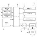
- FIG. 2 is a control block diagram of the vehicle.
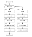
- FIG. 3 is a flowchart illustrating motor control in a vehicle.
- FIG. 4 is a flowchart illustrating the assist ratio correction calculation.
- FIG. 5 is a diagram illustrating the relationship between the rotation speed of the crank and the driver's oxygen intake.
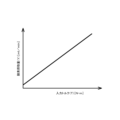
- FIG. 6 is a diagram illustrating the relationship between the input torque and the driver's oxygen intake.
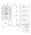
- FIG. 7 is a control block diagram of the vehicle.
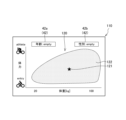
- FIG. 8 is a diagram showing a screen displayed on the input device while the driver is driving the vehicle.
- FIG. 9 is a diagram showing an example of an exercise intensity setting map on the exercise intensity setting screen.
- FIG. 1 is a side view illustrating an overview of a vehicle according to an embodiment of the present invention.
- FIG. 2 is a control block diagram of the vehicle.
- FIG. 3 is a flowchart illustrating motor
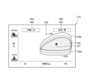
- FIG. 10 is a diagram showing an exercise intensity distribution region when age is input on the exercise intensity setting screen of FIG.
- FIG. 11 is a diagram showing an exercise intensity distribution region when gender is further input on the exercise intensity setting screen of FIG.
- FIG. 12 is a diagram showing a state in which the driver has moved the pointer within the exercise intensity setting map on the exercise intensity setting screen of FIG.
- FIG. 13 is a diagram showing an exercise intensity setting map in which an older person's exercise intensity distribution region and a younger person's exercise intensity distribution region are displayed superimposed on each other.
- FIG. 14 is a diagram showing a state in which the positions of pointers set by other users are displayed superimposed on the exercise intensity setting map.
- FIG. 15 is a diagram showing a state in which the relationship of the standard maximum oxygen intake amount to age and the relationship of the standard weight to age are displayed.
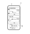
- FIG. 16 is a diagram showing another example of the exercise intensity setting map on the exercise intensity setting screen.
- FIG. 1 is a side view illustrating an overview of bicycle 1.
- FIG. 2 is a control block diagram of bicycle 1.
- the bicycle 1 comprises a frame 2, a front wheel 3a, a rear wheel 3b as a driving wheel, a handlebar 4, a saddle 5, a driving sprocket 6a, a driven sprocket 6b, a chain 6c, a pair of pedals 7, a pair of crank arms 7b as a crank, a crankshaft 7c, a support shaft 8, an electric assist unit 10, a vehicle speed sensor 14, a torque sensor 15, a cadence sensor 16 as an input speed sensor, a controller 20, a power storage unit 30, and an input device 100 as an input unit.
- bicycle 1 is ridden by a rider sitting astride saddle 5 and pedaling crank arm 7b via pedal 7.
- Bicycle 1 drives rear wheel 3b with pedal force (driving torque) transmitted from crank arm 7b to crankshaft 7c and driving force (assist torque) from electric assist unit 10 whose magnitude corresponds to the pedal force.
- bicycle 1 drives rear wheel 3b with power input by the rider and power input from motor 11 (see Figure 2), described later, of electric assist unit 10.
- the frame 2 is a so-called diamond frame that is roughly parallelogram-shaped when viewed from the side.
- a front wheel 3a and a rear wheel 3b are rotatably attached to the frame 2.
- the frame 2 has a front fork 2a that supports the front wheel 3a.
- the front wheel 3a is steered left and right by rotating the front fork 2a through the driver's operation of the handlebars 4.
- the rear wheel 3b rotates around the support shaft 8.
- a driven sprocket 6b and an electric assist unit 10 are attached to the rear wheel 3b.
- the driving torque is transmitted to the driven sprocket 6b via a chain 6c that is looped between the driven sprocket 6b and the driving sprocket 6a, to which the driving force from the crank arm 7b is input.
- a chain 6c instead of the chain 6c, other power transmission members that transmit driving torque, such as a belt, may be used.
- the pedal 7 is used by the driver to input driving torque.
- the pedal 7 is connected to the crankshaft 7c via the crank arm 7b.
- the support shaft 8 is attached to the frame 2.
- the support shaft 8 is arranged so as not to rotate relative to the frame 2.
- the electric assist unit 10 has a motor 11 and a transmission mechanism 13.
- the electric assist unit 10 generates an assist torque that assists the pedaling force applied by the driver.
- the motor 11 is controlled based on a command signal from the controller 20.
- the motor 11 can generate a driving force that assists the power input by the driver, and a regenerative force that converts the rotational energy of the rear wheel 3b into electrical energy.
- the transmission mechanism 13 changes the speed of at least one of the power input from the driver and the power input from the motor 11, and outputs it to the rear wheel 3b. That is, the transmission mechanism 13 may change the speed of only the power input from the driver, may change the speed of only the power input from the motor 11, or may change the speed of both the power input from the driver and the motor 11. Alternatively, the transmission mechanism 13 may not be provided, and the power input from the driver and the power input from the motor 11 may be directly transmitted to the rear wheel 3b. Note that the transmission mechanism 13 is a manual transmission mechanism that is changed based on the operation of the driver, but it may also be an automatic transmission mechanism in which the controller 20 executes the shift control based on the electrical signals from the torque sensor 15 and the cadence sensor 16.
- the vehicle speed sensor 14 detects the speed of the bicycle 1. Specifically, the vehicle speed sensor 14 detects the rotational speed of the rear wheel 3b. The vehicle speed sensor 14 only needs to be able to detect the speed of the bicycle 1, so it may also be able to detect the rotational speed of the front wheel 3a, for example.
- the torque sensor 15 detects the torque of the power input by the driver. Specifically, the torque sensor 15 detects the torque input from the crank arm 7b that is rotated by the driver via the pedal 7. Alternatively, the torque sensor 15 may detect the torque transmitted from the driving sprocket 6a to the driven sprocket 6b via the chain 6c.
- the cadence sensor 16 detects the input speed of the power input by the rider. Specifically, the cadence sensor 16 detects the rotational speed of the crank arm 7b or crankshaft 7c that is driven to rotate by the rider via the pedal 7, i.e., the rotational speed of the driving sprocket 6a. Alternatively, the cadence sensor 16 may detect the rotational speed of the driven sprocket 6b that is driven to rotate by the driving sprocket 6a via the chain 6c.
- the vehicle speed sensor 14, torque sensor 15, and cadence sensor 16 are provided separately from the electric assist unit 10. Alternatively, the vehicle speed sensor 14, torque sensor 15, and cadence sensor 16 may be provided within the electric assist unit 10.
- the controller 20 is composed of a microcomputer equipped with a CPU, RAM, ROM, an input/output interface, etc.
- the controller 20 can also be composed of multiple microcomputers.
- the controller 20 performs various processes by having the CPU read and execute programs stored in the ROM. Specifically, the controller 20 controls the driving force or regenerative force of the motor 11 based on electrical signals corresponding to the magnitude of the pedaling force input from the torque sensor 15 and the rotational speed of the crank arm 7b input from the cadence sensor 16. If the shift mechanism 13 is an automatic shift mechanism, the controller 20 controls the shifting of the shift mechanism 13. If the shift mechanism 13 is not provided, the controller 20 controls the driving force or regenerative force of the motor 11 according to the power input from the rider.
- the controller 20 includes an inverter, a DC-DC converter, etc. for controlling the motor 11.
- the power storage unit 30 is a rechargeable secondary battery such as a nickel-metal hydride battery or a lithium-ion battery.
- the power storage unit 30 supplies power to the motor 11 via the controller 20, and is capable of charging regenerative power from the motor 11.
- the power storage unit 30 supplies power to the controller 20.
- the power storage unit 30 is provided so as to be removable from the frame 2.
- the input device 100 is a portable terminal operated by the rider.
- the input device 100 is composed of a microcomputer equipped with a CPU, RAM, ROM, an input/output interface, etc.
- the input device 100 can also be composed of multiple microcomputers.
- the input device 100 performs various processes by the CPU reading and executing programs stored in the ROM.
- the input device 100 is detachably mounted on the handlebars 4 of the bicycle 1.
- the input device 100 is communicatively connected to the controller 20 via wired or wireless connection.
- the input device 100 has a driving mode input section 41, a physical parameter input section 42, and a target exercise intensity input section 43.
- the input device 100 may be fixed to the bicycle 1.
- the input device 100 also has a communication function between the microcomputer and the controller 20, and the driving mode input unit 41, the physical parameter input unit 42, and the target exercise intensity input unit 43 may be provided separately from the input device 100.
- the driving mode input unit 41 is an input unit that can input the driving mode of the bicycle 1.
- the bicycle 1 has a standard mode that is used during normal riding, and a fat burning mode in which the exercise intensity is set higher than in the standard mode.
- the rider can switch between the standard mode and the fat burning mode by inputting from the driving mode input unit 41.
- the physical parameter input unit 42 is an input unit that can input the physical parameters of the driver.
- the physical parameters are at least one of the driver's gender, weight, age, exercise experience, and physical strength.
- the target exercise intensity input unit 43 is an input unit that can input a target exercise intensity, which is the exercise intensity required by the driver.
- the target exercise intensity can be input based on the range of average driving intensity calculated based on the physical parameters of the driver. If the driver requires a higher or lower exercise intensity, it is also possible to input an exercise intensity outside the range of average driving intensity.
- control for setting the exercise intensity on the bicycle 1 will be described with reference to Figures 3 to 6.
- a case where the control is executed by the controller 20 will be described as an example. This is not limiting, and for example, some of the controls may be executed by the input device 100 and other controls may be executed by the controller 20.
- the control for setting the exercise intensity is executed by the controller 20 at regular time intervals.
- FIG. 3 is a flowchart explaining the control of the motor 11 in the bicycle 1.
- FIG. 4 is a flowchart explaining the assist ratio correction calculation.
- FIG. 5 is a diagram explaining the relationship between the rotation speed of the crank arm 7b and the oxygen intake of the rider.
- the horizontal axis is the rotation speed [rpm] of the crank arm 7b that is rotated by the rider via the pedal 7, and the vertical axis is the oxygen intake (X) [ml/min] of the rider.
- FIG. 6 is a diagram explaining the relationship between the input torque and the oxygen intake of the rider.
- the horizontal axis is the torque [N ⁇ m] input from the crank arm 7b that is rotated by the rider via the pedal 7, and the vertical axis is the oxygen intake (Y) [ml/min] of the rider relative to the input torque.
- step S101 the controller 20 determines whether the driving mode of the bicycle 1 is the standard mode or the fat burning mode. If it is determined in step S101 that the driving mode of the bicycle 1 is the standard mode, the process proceeds to step S102.
- step S102 the controller 20 calculates the speed of the bicycle 1. Specifically, the controller 20 calculates the speed of the bicycle 1 from the rotational speed of the rear wheel 3b and the outer diameter of the rear wheel 3b based on the electrical signal input from the speed sensor 14.
- step S103 the controller 20 calculates the torque of the power input by the driver. Specifically, the controller 20 calculates the magnitude of the torque input by the driver out of the torque transmitted to the rear wheel 3b, based on the torque input via the crank arm 7b detected by the torque sensor 15 and the gear ratio of the transmission mechanism 13. At this time, the controller 20 processes the electrical signal output in a sine wave form as the driver alternately pedals the left and right pedals 7, and calculates the magnitude of the torque input to the crankshaft 7c.
- step S104 the controller 20 calculates the assist ratio, which is the ratio between the power [W] input to the crankshaft 7c and the power [W] output by the motor 11.
- the assist ratio may also be calculated from the ratio between the power [W] input by the driver and the power [W] generated by the motor 11 among the torques transmitted to the rear wheel 3b. In this case, since this is the ratio of powers on the same shaft and the rotation speeds are the same, it is also possible to use the ratio of each torque as the assist ratio.
- step S105 the controller 20 calculates the driving force or regenerative force generated by the motor 11 based on the assist ratio calculated in step S104.
- step S106 the controller 20 controls the motor 11 based on the driving force or regenerative force calculated in step S105.
- step S101 determines whether the bicycle 1 is in fat burning mode. If it is determined in step S101 that the bicycle 1 is in fat burning mode, the process proceeds to step S107.
- step S107 to step S109 is similar to the processing from step S101 to step S103, so a description thereof will be omitted here.
- step S110 the controller 20 executes an assist ratio correction calculation to correct the assist ratio.
- the assist ratio correction calculation will be described in detail below with reference to FIG. 4.
- step S201 of FIG. 4 the controller 20 executes a cadence calculation. Specifically, the controller 20 calculates the rotation speed of the crankshaft 7c that is rotated by the rider via the pedal 7 and crank arm 7b, based on the electrical signal input from the cadence sensor 16. At this time, the controller 20 performs waveform processing on the electrical signal that is output in the form of a sine wave when the rider alternately pedals the left and right pedals 7, to calculate the rotation speed of the crank arm 7b.
- step S202 the controller 20 calculates an oxygen intake amount (X) as the first oxygen intake amount of the driver based on the rotation speed of the crank arm 7b calculated in step S201.
- the oxygen intake amount (X) is an oxygen intake amount estimated from the internal work amount of the driver.
- the oxygen intake (X) of the rider can be estimated based on equation (1) from the rotational speed of the crank arm 7b detected by the cadence sensor 16.
- step S203 the controller 20 calculates the pedal input torque by the driver. Specifically, the controller 20 calculates the torque input to the crankshaft 7c, which is rotated by the driver via the pedal 7 and crank arm 7b, based on the electrical signal input from the torque sensor 15. At this time, the controller 20 processes the electrical signal output in a sine wave form as the driver alternately pedals the left and right pedals 7, and calculates the magnitude of the torque input to the crankshaft 7c.
- step S204 the controller 20 calculates an oxygen intake amount (Y) as the second oxygen intake amount of the driver based on the torque input from the crank arm 7b calculated in step S203.
- the oxygen intake amount (Y) is an oxygen intake amount estimated from the external work amount of the driver.
- the driver's oxygen intake (Y) can be estimated based on equation (2) from the torque input from crank arm 7b detected by torque sensor 15.
- step S205 the driver's physical parameters are input to the controller 20 based on the driver's operation of the input device 100 (physical parameter input unit 42).
- step S206 the controller 20 determines whether or not the driver's physical parameters have been input. If it is determined in step S206 that the driver's physical parameters have been input, the process proceeds to step S207, where the input values input by the driver are selected. On the other hand, if it is determined in step S206 that the driver's physical parameters have not been input, the process proceeds to step S208, where a preset standard value is selected.
- the entered values will be selected for the items that have been entered, and standard values will be selected for the items that have not been entered.
- step S209 the controller 20 calculates the driver's oxygen intake at rest (U) based on the driver's physical parameters. Specifically, the controller 20 calculates the resting oxygen intake (U), which is the driver's oxygen intake at rest, based on values statistically determined from the driver's physical parameters such as gender, weight, age, exercise experience, and physical strength.
- step S210 the controller 20 calculates the driver's maximum oxygen intake (V). Specifically, the controller 20 calculates the driver's maximum oxygen intake (V) based on values statistically determined from the driver's physical parameters, such as gender, weight, age, exercise experience, and physical strength.
- the accuracy of estimating the total oxygen intake (Z) can be improved by calculating the driver's workload by combining the rotation speed detected by the cadence sensor 16, i.e., the oxygen intake (X) estimated from the driver's internal workload, and the torque detected by the torque sensor 15, i.e., the oxygen intake (Y) estimated from the driver's external workload.
- step S213 the controller 20 executes waveform processing. Normally, when estimating the driver's total oxygen intake (V), it is possible to estimate it accurately by using the driver's heart rate. However, in this embodiment, in order to eliminate the inconvenience of the driver having to wear a heart rate detection sensor, etc., a heart rate detection sensor is not used, and instead the cadence sensor 16 and torque sensor 15 are used. In step S213, since the value of the driver's maximum oxygen intake (V) varies linearly with the amount of exercise, waveform processing is performed to approximate the value to the exercise intensity calculated based on the driver's heart rate.
- V maximum oxygen intake
- step S214 the target exercise intensity targeted by the driver is input to the controller 20 based on information input by the driver through operation of the input device 100 (target exercise intensity input unit 43).
- the driver can input the target exercise intensity from the input device 100, so that it is possible to input an exercise intensity outside the range of average driving intensity when a higher or lower exercise intensity is required, rather than just within the range of average driving intensity calculated based on the driver's physical parameters.
- step S215 the controller 20 corrects the assist ratio, which is the ratio of the torque input by the driver to the torque generated by the motor 11 among the torques transmitted to the rear wheels 3b calculated in step S109, based on the values of the driver's target driving intensity and the waveform-processed exercise intensity (W) in the driver's exercise state. Specifically, when the driver's target driving intensity is smaller than the exercise intensity (W) in the driver's exercise state, the controller 20 increases the proportion of the torque generated by the motor 11. On the other hand, when the driver's target driving intensity is greater than the exercise intensity (W) in the driver's exercise state, the controller 20 decreases the proportion of the torque generated by the motor 11. After the correction of the assist ratio is performed in step S215, the process proceeds to step S111.
- the assist ratio is the ratio of the torque input by the driver to the torque generated by the motor 11 among the torques transmitted to the rear wheels 3b calculated in step S109.
- step S111 the controller 20 calculates the driving force or regenerative force to be generated by the motor 11 based on the assist ratio calculated in step S111. Specifically, when increasing the proportion of the torque generated by the motor 11, the controller 20 transmits an electrical signal to the motor 11 to output a larger torque. On the other hand, when decreasing the proportion of the torque generated by the motor 11, the controller 20 transmits an electrical signal to the motor 11 to output a smaller torque. Furthermore, when the torque generated by the motor 11 is insufficient even when set to 0, the controller 20 performs regenerative control on the motor 11 to generate a resistance force in the opposite direction to the torque input by the driver. Therefore, by controlling the driving force or regenerative force of the motor 11, the motor 11 can be controlled to approach the driver's target exercise intensity over a wide range.
- step S106 the controller 20 controls the motor 11 based on the driving force or regenerative force calculated in step S111.
- the controller 20 calculates the workload of the driver based on the torque detected by the torque sensor 15 and the rotation speed detected by the cadence sensor 16, estimates the total oxygen intake (Z) of the driver from the workload, estimates the maximum oxygen intake (V) of the driver from the driver's physical parameters, and controls the motor 11 so that the exercise intensity calculated from the total oxygen intake (Z) and the maximum oxygen intake (V) approaches the target exercise intensity of the driver.
- the driver's total oxygen intake (Z) can be estimated from the torque detected by the torque sensor 15 and the rotation speed detected by the cadence sensor 16, and the maximum oxygen intake (V) can be estimated from the driver's physical parameters, thereby allowing the exercise intensity of the driver to be calculated. Therefore, the motor 11 can be controlled to match the target exercise intensity required by the driver, without the driver having to wear a heart rate detection sensor or the like.
- the provision of the speed change mechanism 13 allows the driving force and regenerative force of the motor 11 to be increased based on the speed change ratio, making it possible to control the intensity of the exercise to approach the driver's target intensity over a wider range.
- the controller 20 controls the motor 11 so that the exercise intensity calculated from the total oxygen intake (Z) and maximum oxygen intake (V) described above approaches the target exercise intensity.
- the motor 11 is controlled so that the exercise intensity approaches the target exercise intensity, making it possible to set the exercise intensity according to the driver's intentions.
- the driver inputs the target exercise intensity from the input device 100, and the motor 11 is controlled based on the input target exercise intensity, so that, depending on the driver's request, the motor 11 can be controlled to reduce the driver's load and make driving easier, or to provide the driver with an optimal load for burning fat.
- FIG. 7 is a control block diagram of bicycle 1.
- FIG. 8 is a diagram showing a screen displayed on input device 100 while the rider is riding bicycle 1. Note that the overall configuration of bicycle 1 is the same as that shown in FIG. 1, so a description thereof will be omitted.
- the bicycle 1 may be equipped with a biosensor, such as a heart rate sensor 17, that can acquire information that is the basis for calculating the exercise load.
- a biosensor such as a heart rate sensor 17, that can acquire information that is the basis for calculating the exercise load.
- the heart rate sensor 17 detects the driver's heart rate. Specifically, the heart rate sensor 17 is attached to a part of the driver's body, such as the wrist, and detects the driver's heart rate by shining light toward the skin and detecting the light reflected by blood vessels.
- the controller 20 controls the driving force or regenerative force of the motor 11 based on electrical signals corresponding to the magnitude of the pedaling force input from the torque sensor 15, the rotational speed of the crank arm 7b input from the cadence sensor 16, and the driver's heart rate detected by the heart rate sensor 17.
- the input device 100 is a mobile terminal operated by the rider.
- the input device 100 is used to set the rider's target exercise intensity.
- the input device 100 is a smartphone that is communicatively connected to the controller 20 of the bicycle 1 via a wired or wireless connection.
- the input device 100 has a touch screen 101 that serves as both a display unit and an input unit, and a communication unit 102. Note that the input device 100 does not have to be a smartphone, and may instead be a device that has equivalent functions and is fixed to the bicycle 1.
- the touch screen 101 has a driving mode setting screen 141, a physical parameter input section 42, and an exercise intensity setting screen 110.
- the driving mode setting screen 141 is a screen for selecting the driving mode of the bicycle 1.
- the bicycle 1 has a standard mode that is used during normal riding, and a fat burning mode in which the exercise intensity is set higher than in the standard mode.
- the rider can set either the standard mode or the fat burning mode by inputting information on the driving mode setting screen 141.
- the touch screen 101 displays a status display section 103 and an exercise intensity graph 104.
- the status display unit 103 displays the current status of the driver. In this case, if the driver is performing aerobic exercise that burns fat, the status display unit 103 displays a message indicating that fat is being burned. This makes it possible to visually convey the current status of the driver. In addition, the status display unit 103 can display warming up, aerobic exercise, anaerobic exercise, maximum intensity, etc.
- the exercise intensity graph 104 displays the current exercise intensity level of the driver in a graph. This makes it possible to visually communicate the exercise intensity of the driver.
- the exercise intensity level is calculated based on the amount of oxygen intake calculated by the controller 20 from the magnitude of the pedaling force input from the torque sensor 15 and the rotational speed of the crank arm 7b input from the cadence sensor 16, or based on the driver's heart rate detected by the heart rate sensor 17.
- the physical parameter input unit 42 is an input unit that can input the physical parameters of the driver.
- the physical parameters include the driver's gender, weight, age, and exercise experience.
- the exercise intensity setting screen 110 is a screen for setting the driver's target exercise intensity.
- the exercise intensity setting screen 110 will be described in detail later with reference to Figures 9 to 16.
- the communication unit 102 is a communication module capable of communicating with an external server (not shown).
- the communication unit 102 can perform data communication using a mobile phone communication network, a wireless LAN (Local Area Network), etc.
- FIG. 9 is a diagram showing an example of the exercise intensity setting map 120 on the exercise intensity setting screen 110.
- FIG. 10 is a diagram showing the exercise intensity distribution area 122 when age is input on the exercise intensity setting screen 110 of FIG. 9.
- FIG. 11 is a diagram showing the exercise intensity distribution area 122 when gender is further input on the exercise intensity setting screen 110 of FIG. 10.
- FIG. 12 is a diagram showing a state in which the driver has moved the pointer 121 within the exercise intensity setting map 120 on the exercise intensity setting screen 110 of FIG. 11.
- FIG. 13 is a diagram showing a state in which the older person exercise intensity distribution area 122a and the younger person exercise intensity distribution area 122b are displayed superimposed on the exercise intensity setting map 120.
- FIG. 14 is a diagram showing a state in which the position of the pointer 121 set by another user is displayed superimposed on the exercise intensity setting map 120.
- FIG. 15 is a diagram showing a state in which the relationship between the standard maximum oxygen intake and age and the relationship between the standard body weight and age are displayed.
- FIG. 16 shows another example of the exercise intensity setting map 120 on the exercise intensity setting screen 110.
- the exercise intensity setting screen 110 is a screen for setting the rider's target exercise intensity.
- the exercise intensity setting screen 110 is displayed when the bicycle 1 is set to fat burning mode.
- the exercise intensity setting screen 110 is displayed when the rider intentionally selects fat burning mode instead of standard mode, making it possible to set a target exercise intensity that matches the rider's intentions.
- the exercise intensity setting screen 110 displays the body parameter input section 42 and an exercise intensity setting map 120.
- the physical parameter input section 42 has an age input section 42a and a gender input section 42b.
- the age input section 42a is an input section for inputting the age of the driver.
- a number input pad (not shown) for inputting numbers is displayed on the exercise intensity setting screen 110.
- age which is one of the physical parameters, is input.
- the gender input section 42b is an input section for inputting the gender of the driver.
- gender options are displayed on the exercise intensity setting screen 110 (not shown).
- gender which is one of the physical parameters, is input.
- one of the vertical and horizontal axes represents one of the driver's physical fitness parameters, and the other represents one of the driver's physical parameters.
- the vertical axis represents physical fitness that is set based on the maximum oxygen intake, which is one of the driver's physical fitness parameters
- the horizontal axis represents the driver's body weight [kg], which is also one of the driver's physical parameters.
- the vertical axis is set so that it approaches the physically strong "athlete” as it goes up, and approaches the beginner “entry” as it goes down.
- the horizontal axis is set so that weight increases as it goes to the right, and decreases as it goes to the left.
- the physical fitness parameters are not limited to being set based on the driver's maximum oxygen intake or maximum heart rate, but may be any index that is correlated with the maximum oxygen intake.
- Examples of physical fitness parameters include the driver's Ankle Brachial Index (ABI), Brachial-Ankle Pulse Wave Velocity (baPWV), Acceleration Pleth Wave Coefficient, High Density Lipoprotein (HDL), Lower Limb Skeletal Muscle Mass, Vital Capacity, Muscle Strength Measurement Values, Physical Fitness Measurement Values, etc.
- the exercise intensity setting map 120 displays a pointer 121 and an exercise intensity distribution area 122.
- the pointer 121 indicates the weight and physical strength values that are set by default.
- the pointer 121 is displayed in a position approximately in the center of the exercise intensity distribution area 122.
- the pointer 121 can be moved from the default position to another position by the rider's operation.
- the target exercise intensity for the bicycle 1 is set based on the weight and physical strength values at that position.
- the target exercise intensity for the bicycle 1 is set based on the weight and physical strength values at the default position.
- the exercise intensity for the bicycle 1 can be set based on the position where the pointer 121 is set in the exercise intensity setting map 120.
- the exercise intensity distribution area 122 is set by default around the pointer 121 and is an area set based on default information of the driver's physical parameters.
- the exercise intensity distribution area 122 is set based on the physical parameters of a group including the driver's age. Specifically, the exercise intensity distribution area 122 is set to an area where the driver can perform aerobic exercise that burns fat based on the driver's physical parameters.
- the exercise intensity distribution area 122 is an area set including all genders based on the relationship between the driver's age and average body weight, and the relationship between the driver's age and average maximum oxygen intake.
- the exercise intensity distribution area 122 is set as an area plotted by taking into account the distribution of average body weight to the relationship between the driver's age and average maximum oxygen intake, regardless of the driver's gender. In the default state where the driver's physical parameters are not input, the exercise intensity distribution area 122 is set to the widest area.
- the exercise intensity distribution area 122 changes to become narrower. This is because the group that includes the driver's age is narrowed down, and groups that do not include the driver's age are excluded. In this way, the display of the exercise intensity distribution area 122 changes based on the input physical parameters.
- the driver's age is entered as "35 years old," so the exercise intensity distribution area 122 changes to an area of average exercise intensity based on the physical parameters of a group that includes the driver's age.
- the group that includes the driver's age is set to, for example, a range from 35 to 39 years old in 5-year increments, or a range from 30 to 39 years old in 10-year increments.
- the exercise intensity distribution area 122 narrows. This is because the group that includes the driver's gender is narrowed down, and groups that do not include the driver's gender are excluded. In this way, the display of the exercise intensity distribution area 122 changes based on the input physical parameters.
- the exercise intensity distribution area 122 changes to the area of average exercise intensity based on the physical parameters of the group that includes the driver's age.
- the group that includes the driver's age is set to "male" out of all genders.
- the exercise intensity distribution area 122 changes to become even narrower. That is, the exercise intensity distribution area 122 changes to become narrower as more types of physical parameters are input. Thus, the area is narrowed down to a group that includes the physical parameters input by the driver, and groups that do not include the physical parameters of the driver are excluded, thereby improving the accuracy of the area indicated by the exercise intensity distribution area 122.
- the driver can change the target exercise intensity from the default target exercise intensity set based on the weight and physical strength values to the target exercise intensity desired by the driver by moving the pointer 121 from the state shown in FIG. 11.
- the target exercise intensity changes to a higher value.
- the target exercise intensity changes to a lower value.
- the target exercise intensity is set to match the physical parameters of a person heavier than the driver, so the target exercise intensity changes to a higher value.
- the target exercise intensity is set to match the physical parameters of a person lighter than the driver, so the target exercise intensity changes to a lower value.
- the driver moves the pointer 121 significantly from the default position toward the physical strength "athlete," so the target exercise intensity changes to be significantly higher.
- the controller 20 sets the assist ratio, which is the ratio between the power [W] input to the crankshaft 7c and the power [W] output by the motor 11, based on the target exercise intensity input from the input device 100. Specifically, when the exercise intensity is reduced, the controller 20 increases the proportion of the torque generated by the motor 11. On the other hand, when the exercise intensity is increased, the controller 20 decreases the proportion of the torque generated by the motor 11.
- the assist ratio may be set from the ratio between the power [W] input by the driver and the power [W] generated by the motor 11 out of the torque transmitted to the rear wheel 3b. In this case, since it is the ratio of powers on the same axis and the rotation speeds are the same, it is also possible to use the ratio of each torque as the assist ratio.
- the controller 20 When increasing the proportion of the torque generated by the motor 11, the controller 20 transmits an electrical signal to the motor 11 to output a larger torque. On the other hand, when decreasing the proportion of the torque generated by the motor 11, the controller 20 transmits an electrical signal to the motor 11 to output a smaller torque. Furthermore, if the torque generated by the motor 11 is insufficient even when set to 0, the controller 20 controls the motor 11 to regenerate so as to generate a resistance force in the opposite direction to the torque input by the driver. Therefore, by controlling the driving force or regenerative force of the motor 11, the motor 11 can be controlled to approach the target exercise intensity required by the driver over a wide range.
- the exercise intensity setting screen 110 of the input device 100 displays an exercise intensity setting map 120 in which one of the vertical and horizontal axes represents one of the rider's physical parameters and the other represents one of the rider's physical parameters.
- the rider can set the exercise intensity for the bicycle 1 simply by setting the position of the pointer 121 indicating the values of the physical parameter and physical parameter with reference to the exercise intensity distribution area 122 set based on the default information for the physical parameters displayed on the exercise intensity setting map 120. Therefore, the target exercise intensity can be set with an intuitive operation, reducing the burden on the rider in setting the target exercise intensity.
- the bicycle 1 is equipped with a speed change mechanism 13
- the driving force and regenerative force of the motor 11 can be increased based on the speed change ratio. This allows control to be performed to approach the target exercise intensity required by the rider over a wider range.
- the exercise intensity setting map 120 displays an older person's exercise intensity distribution area 122a and a younger person's exercise intensity distribution area 122b superimposed on the exercise intensity distribution area 122.
- the older person exercise intensity distribution region 122a is set based on default information for the physical parameters of a group older than the driver.
- the younger person exercise intensity distribution region 122b is set based on default information for the physical parameters of a group younger than the driver.
- the driver's age is entered as "35 years old," so the group that includes the driver's age is set to the range of 30 to 39 years old in increments of 10 years.
- the older exercise intensity distribution area 122a is set to the +10 year group, that is, the range of 40 to 49 years old.
- the younger exercise intensity distribution area 122b is set to the -10 year group, that is, the range of 20 to 29 years old.
- the driver By displaying the older person exercise intensity distribution area 122a and the younger person exercise intensity distribution area 122b, if the driver feels that their subjective age is higher than their actual age, they can set a target exercise intensity within the older person exercise intensity distribution area 122a for the next older age group, and if the driver feels that their subjective age is lower than their actual age, they can set a target exercise intensity within the younger person exercise intensity distribution area 122b for the next younger age group.
- the older person exercise intensity distribution area 122a and the younger person exercise intensity distribution area 122b change in accordance with the physical parameters input by the driver, becoming narrower as the number of types of physical parameters input increases.
- the position of a pointer 121 set by another user can be obtained from the server and displayed superimposed on the exercise intensity setting map 120.
- members who belong to a particular team are displayed so that they can be easily identified by using different symbols (here, two types: "+” and "-”) or different colors for each age group that the member belongs to.
- the touch screen 101 of the input device 100 can display the relationship of standard maximum oxygen intake to age for men and women, and plot the relationship between the driver's age and maximum oxygen intake. This allows the driver to compare his or her own maximum oxygen intake value with the standard value.
- the touch screen 101 of the input device 100 can also display the relationship between standard weight and age for men and women, and plot the relationship between the driver's age and weight. This allows the driver to compare their own weight value with the standard value.
- the driver's date of birth may be input from the age input unit 42a. This allows the driver's age at that time to be calculated from the date data held by the input device 100. Therefore, even if some time has passed since the driver last input his/her age, the driver will not need to re-input his/her age.
- the horizontal axis may represent the driver's age, which is one of the physical parameters. In this case, the same effect can be obtained as when the horizontal axis represents weight.
- the controller 20 is configured to calculate the rider's workload based on the torque detected by the torque sensor 15 and the rotational speed detected by the cadence sensor 16, estimate the rider's total oxygen intake (Z) from the workload, estimate the rider's maximum oxygen intake (V) from the rider's physical parameters, and control the motor 11 so that the exercise intensity calculated from the total oxygen intake (Z) and the maximum oxygen intake (V) approaches the rider's target exercise intensity.
- the driver's total oxygen intake (Z) is estimated from the torque detected by the torque sensor 15 and the rotation speed detected by the cadence sensor 16, and the maximum oxygen intake (V) is estimated from the driver's physical parameters, making it possible to calculate the driver's exercise intensity. Therefore, the motor 11 can be controlled to match the target exercise intensity required by the driver, without the driver having to wear a heart rate detection sensor or the like.
- the bicycle 1 further includes an input device 100 for inputting physical parameters, the physical parameters being at least one of the gender, weight, age, exercise experience, and physical strength of the rider.
- the target exercise intensity can be input from the input device 100.
- the driver can input the target exercise intensity from the input device 100, so that it is possible to input an exercise intensity outside the range of average driving intensity when a higher or lower exercise intensity is required, rather than just within the range of average driving intensity calculated based on the driver's physical parameters.
- the controller 20 is configured to control the driving force or regenerative force of the motor 11 according to the power input from the driver.
- the controller 20 transmits an electrical signal to the motor 11 to output a larger torque
- the controller 20 transmits an electrical signal to the motor 11 to output a smaller torque.
- the controller 20 regeneratively controls the motor 11 to generate a resistance force in the opposite direction to the torque input by the driver. Therefore, by controlling the driving force or regenerative force of the motor 11, it is possible to control the motor 11 to approach the driver's target exercise intensity over a wide range.
- the bicycle 1 further includes a transmission mechanism 13 that changes the speed of at least one of the power input from the rider and the power input from the motor 11 and outputs it to the rear wheel 3b.
- the controller 20 is configured to change the speed of the transmission mechanism 13 in response to the power input from the driver and to control the driving force or regenerative force of the motor 11.
- the provision of the speed change mechanism 13 allows the driving force and regenerative force of the motor 11 to be increased based on the speed change ratio, making it possible to control the intensity of the exercise to approach the driver's target intensity over a wider range.
- the controller 20 is configured to estimate the total oxygen intake (Z) from the oxygen intake (X) estimated from the rotation speed detected by the cadence sensor 16, the oxygen intake (Y) estimated from the torque detected by the torque sensor 15, and the driver's resting oxygen intake (U) at rest obtained from physical parameters.
- the accuracy of estimating the total oxygen intake (Z) can be improved by estimating the oxygen intake (X) based on the internal work amount estimated from the rotation speed detected by the cadence sensor 16 and the oxygen intake (Y) based on the external work amount estimated from the torque detected by the torque sensor 15.
- the bicycle 1 can be switched between a standard mode and a fat burning mode in which the exercise intensity is set higher than that in the standard mode, and the controller 20 is configured to control the motor 11 in the fat burning mode so that the exercise intensity calculated from the total oxygen intake (Z) and the maximum oxygen intake (V) approaches the target exercise intensity.
- the motor 11 is controlled so that the exercise intensity approaches the target exercise intensity, making it possible to set the exercise intensity according to the driver's intentions.
- the input unit is an input device 100 that is operated by the driver.
- physical parameters and target exercise intensity can be input from the input device 100, so for example, physical parameters and target exercise intensity can be input in advance into the input device 100, and then the exercise intensity can be controlled by attaching it to the bicycle 1.
- the torque sensor 15 detects the torque input from the crank arm 7b that is rotated by the rider via the pedal 7, and the cadence sensor 16 detects the rotational speed of the crank arm 7b.
- This configuration is applied to a bicycle 1 in which a rider rotates the crank arm 7b via pedals 7, and the motor 11 can be controlled to match the target exercise intensity required by the rider using the bicycle 1.
- JP2019-182227A discloses an electrically assisted bicycle (vehicle) equipped with an electric motor, a pedaling force sensor that detects the pedaling force of the driver, an electric motor that applies an assist force to auxiliary drive the wheels based on the pedaling force, a heart rate acquisition unit that acquires the driver's heart rate, and a controller that determines the assist force so as to bring the driver's heart rate closer to a target heart rate.
- exercise intensity is set by inputting information into the age input area and exercise intensity input area displayed on the controller display.
- the rider simply inputs information into each area, making it difficult to understand how to set the exercise intensity.
- an input device 100 for setting a target exercise intensity for the rider displays an exercise intensity setting map 120 in which one of the vertical and horizontal axes is one of the rider's physical parameters and the other is one of the rider's physical parameters, and has an exercise intensity setting screen 110 for setting the target exercise intensity, and the exercise intensity setting map 120 displays a pointer 121 indicating the values of the physical parameter and physical parameter set by default, and an exercise intensity distribution area 122 set by default around the pointer 121 and based on the default information of the physical parameter, and the target exercise intensity for the bicycle 1 can be set based on the position where the pointer 121 is set in the exercise intensity setting map 120.
- an exercise intensity setting map 120 is displayed on the exercise intensity setting screen 110 of the input device 100, in which one of the vertical and horizontal axes represents one of the rider's physical parameters and the other represents one of the rider's physical parameters.
- the rider can set the target exercise intensity for the bicycle 1 simply by setting the position of a pointer 121 indicating the values of the physical parameter and physical parameter with reference to an exercise intensity distribution area 122 set based on the default information for the physical parameters displayed on the exercise intensity setting map 120. This allows the rider to set the target exercise intensity with an intuitive operation, reducing the burden on the rider in setting the target exercise intensity.
- the input device 100 has a physical parameter input unit 42 for inputting the physical parameters of the driver, and the display of the exercise intensity distribution area 122 changes based on the input physical parameters.
- the physical parameters include the driver's gender, weight, age, and exercise experience, and the more types of physical parameters that are input, the narrower the exercise intensity distribution area 122 becomes.
- the group is narrowed down to one that includes the physical parameters input by the driver, and groups that do not include the physical parameters of the driver are excluded, thereby improving the accuracy of the area indicated by the exercise intensity distribution area 122.
- the input device 100 further includes a driving mode setting screen 141 for selecting between a standard mode used during normal driving and a fat burning mode in which the target exercise intensity is set higher than that in the standard mode, and the exercise intensity setting screen 110 is displayed when the fat burning mode is set.
- the exercise intensity setting screen 110 is displayed when the driver intentionally selects the fat burning mode instead of the standard mode, making it possible to set a target exercise intensity that matches the driver's intentions.
- the vertical axis of the exercise intensity setting map 120 represents the driver's physical strength based on the maximum oxygen intake (V), and the horizontal axis represents the driver's weight.
- the vertical axis represents the driver's physical strength and the horizontal axis represents the driver's weight, allowing the driver to intuitively set a target exercise intensity in comparison with their own weight and physical strength.
- the exercise intensity distribution area 122 is set based on the physical parameters of a group that includes the driver's age, and the exercise intensity setting map 120 displays an older exercise intensity distribution area 122a set based on default information of the physical parameters of a group older than the driver, and a younger exercise intensity distribution area 122b set based on default information of the physical parameters of a group younger than the driver, superimposed on the exercise intensity distribution area 122.
- the input device 100 is equipped with a communication unit 102 capable of communicating with an external server, and the position of a pointer 121 set by another user can be obtained from the server and displayed superimposed on the exercise intensity setting map 120.
- the driver can refer to the target exercise intensity set by a member of a particular team, for example, and can set the target exercise intensity to the same as that set by other members, or to a higher target exercise intensity than that set by other members.
- the input device 100 is a smartphone that is connected to the bicycle 1 via a wired or wireless connection.
- physical parameters and target exercise intensity can be input from the input device 100, so for example, physical parameters and target exercise intensity can be input in advance into the input device 100, and then the target exercise intensity can be set by attaching it to the bicycle 1.
- the vehicle is a bicycle 1, but the vehicle may be another vehicle that assists the driver's power with the power of a motor, such as an electrically assisted kickboard or an electrically assisted wheelchair. If the vehicle is an electrically assisted kickboard, the power input by the driver kicking the ground with one foot is assisted by controlling the motor. If the vehicle is an electrically assisted wheelchair, the power input by the driver turning the wheels with their arms is assisted by controlling the motor.
- a motor such as an electrically assisted kickboard or an electrically assisted wheelchair.
- the electric assist unit 10 is attached to the rear wheel 3b.
- the electric assist unit 10 may be attached to the front wheel 3a, and the front wheel 3a may be used as the driving wheel.
- the input device 100 may also be a smartphone or the like that is connected to the controller 20 via wired or wireless communication to transmit and receive data and can connect to the Internet.
- controller 20 or the input device 100 may be connected to a cloud server (not shown) on the Internet, and the cloud server may be used as the execution entity for some of the above-mentioned processes executed by the controller 20 and the input device 100.
- the controller 20 (or the controller 20 and the input device 100) mounted on the bicycle 1 is described as an example of the entity that executes the control to set the exercise intensity on the bicycle 1, but the entity that executes the control may be any one or a combination of the controller 20, the input device 100, and the cloud server. Therefore, any one or a combination of the controller 20, the input device 100, and the cloud server corresponds to the controller.
- the series of processes in the bicycle 1 described above may be provided as a program for a computer to execute.
- the program for executing the series of processes described above may be provided on a computer-readable storage medium.
- the various programs executed by the computer may be stored on a non-transitory storage medium such as a CD-ROM.
Landscapes
- Engineering & Computer Science (AREA)
- Mechanical Engineering (AREA)
- Chemical & Material Sciences (AREA)
- Combustion & Propulsion (AREA)
- Transportation (AREA)
- Electric Propulsion And Braking For Vehicles (AREA)
Abstract
[課題]運転者が心拍数検出センサ等を装着することなく、運転者の目標運動強度に沿うようにモータを制御する。 [解決手段]運転者により入力される動力とモータから入力される動力とによって駆動輪が駆動される車両は、運転者により入力される動力のトルクを検出するトルクセンサと、運転者により入力される動力の入力速度を検出する入力速度センサと、前記モータを制御するコントローラと、を備え、前記コントローラは、前記トルクセンサが検出したトルクと前記入力速度センサが検出した入力速度とに基づき運転者の仕事量を演算し、当該仕事量から運転者の酸素摂取量を推定し、運転者の身体パラメータから当該運転者の最大酸素摂取量を推定し、前記酸素摂取量と前記最大酸素摂取量とから演算される運動強度が、運転者の目標運動強度に近付くように前記モータを制御する、ように構成される。
Description
本発明は、車両、入力装置、車両の制御方法、入力装置の制御方法、及びプログラムに関する。
特許文献1には、運転者がペダルを漕ぐ際の踏力を歪みゲージによって検出し、踏力が有酸素運動が可能となる踏力レベルよりも大きい場合には、電動モータを駆動して踏力を補助する電動力を発生させ、当該踏力レベルよりも小さい場合には、電動モータの回転抵抗によって踏力に負荷力を印加する電動アシスト自転車(車両)が開示されている。
しかしながら、特許文献1の電動アシスト自転車では、心拍数検出センサを用いて検出した運転者の心拍数に基づいて、有酸素運動が可能となる踏力レベルを設定している。そのため、電動アシスト自転車を運転する際に、運転者は、心拍数を検出するための心拍数検出センサを装着しなければならない煩わしさがある。
本発明は、上記の問題点に鑑みてなされたものであり、運転者が心拍数検出センサ等を装着することなく、運転者の目標運動強度に沿うようにモータを制御することを目的とする。
本発明のある態様では、運転者により入力される動力とモータから入力される動力とによって駆動輪が駆動される車両は、運転者により入力される動力のトルクを検出するトルクセンサと、運転者により入力される動力の入力速度を検出する入力速度センサと、前記モータを制御するコントローラと、を備え、前記コントローラは、前記トルクセンサが検出したトルクと前記入力速度センサが検出した入力速度とに基づき運転者の仕事量を演算し、当該仕事量から運転者の酸素摂取量を推定し、運転者の身体パラメータから当該運転者の最大酸素摂取量を推定し、前記酸素摂取量と前記最大酸素摂取量とから演算される運動強度が、運転者の目標運動強度に近付くように前記モータを制御する、ように構成される。
本発明のある態様によれば、トルクセンサが検出したトルクと入力速度センサが検出した入力速度とから運転者の酸素摂取量を推定し、運転者の身体パラメータから最大酸素摂取量を推定することで、運転者の運動強度を演算することができる。したがって、運転者が心拍数検出センサ等を装着することなく、運転者の目標運動強度に沿うようにモータを制御することができる。
以下、図面を参照して、本発明の実施形態に係る車両としての電動アシスト自転車(以下、単に「自転車」と称する。)1について説明する。
まず、図1及び図2を参照して、自転車1の全体構成について説明する。
図1は、自転車1の概要を説明する側面図である。図2は、自転車1の制御ブロック図である。
図1及び図2に示すように、自転車1は、フレーム2と、前輪3aと、駆動輪としての後輪3bと、ハンドル4と、サドル5と、駆動スプロケット6aと、被駆動スプロケット6bと、チェーン6cと、一対のペダル7と、一対のクランクとしてのクランクアーム7bと、クランクシャフト7cと、支持軸8と、電動アシストユニット10と、車速センサ14と、トルクセンサ15と、入力速度センサとしてのケイデンスセンサ16と、コントローラ20と、蓄電部30と、入力部としての入力装置100と、を備える。
図1に示すように、自転車1は、運転者が跨ってサドル5に着座し、ペダル7を介してクランクアーム7bを漕いで運転するものである。自転車1は、クランクアーム7bからクランクシャフト7cに伝達されるペダル踏力(駆動トルク)と、当該ペダル踏力に応じた大きさの電動アシストユニット10による駆動力(アシストトルク)と、によって後輪3bを駆動するものである。即ち、自転車1は、運転者により入力される動力と電動アシストユニット10の後述するモータ11(図2参照)から入力される動力とによって後輪3bが駆動されるものである。
フレーム2は、側面視略平行四辺形状のいわゆるダイヤモンド型フレームである。フレーム2には、前輪3a及び後輪3bが回転可能に取り付けられる。フレーム2は、前輪3aを支持するフロントフォーク2aを有する。
前輪3aは、運転者のハンドル4の操作によってフロントフォーク2aが回動することで左右に転舵される。
後輪3bは、支持軸8を中心に回転する。後輪3bには、被駆動スプロケット6bと、電動アシストユニット10と、が取り付けられる。
被駆動スプロケット6bには、クランクアーム7bからの駆動力が入力される駆動スプロケット6aとの間に掛け回されたチェーン6cを介して駆動トルクが伝達される。なお、チェーン6cに代えて、駆動トルクを伝達するベルト等の他の動力伝達部材を適用してもよい。
ペダル7は、運転者が駆動トルクを入力するものである。ペダル7は、クランクアーム7bを介してクランクシャフト7cに連結されている。
支持軸8は、フレーム2に取り付けられる。支持軸8は、フレーム2に対して回転不能に設けられる。
図2に示すように、電動アシストユニット10は、モータ11と、変速機構13と、を有する。電動アシストユニット10は、運転者によるペダル踏力をアシストするアシストトルクを発生する。
モータ11は、コントローラ20からの指令信号に基づき制御される。モータ11は、運転者により入力される動力をアシストする駆動力と、後輪3bの回転エネルギを電気エネルギに変換する回生力と、を発生可能である。
変速機構13は、運転者から入力される動力とモータ11から入力される動力との少なくとも一方を変速して後輪3bに出力する。即ち、変速機構13は、運転者から入力される動力のみを変速してもよいし、モータ11から入力される動力のみを変速してもよいし、運転者とモータ11とから入力される動力を共に変速してもよい。また、変速機構13を設けずに、運転者から入力される動力とモータ11から入力される動力とが後輪3bに直接伝達される構成であってもよい。なお、変速機構13は、運転者の操作に基づき変速される手動変速機構であるが、トルクセンサ15やケイデンスセンサ16からの電気信号に基づいてコントローラ20が変速制御を実行する自動変速機構であってもよい。
車速センサ14は、自転車1の速度を検出する。具体的には、車速センサ14は、後輪3bの回転速度を検出する。車速センサ14は、自転車1の速度を検出できればよいので、例えば前輪3aの回転速度を検出するものであってもよい。
トルクセンサ15は、運転者により入力される動力のトルクを検出する。具体的には、トルクセンサ15は、運転者によってペダル7を介して回転駆動されるクランクアーム7bから入力されるトルクを検出する。これに代えて、トルクセンサ15は、駆動スプロケット6aからチェーン6cを介して被駆動スプロケット6bに伝達されたトルクを検出してもよい。
ケイデンスセンサ16は、運転者により入力される動力の入力速度を検出する。具体的には、ケイデンスセンサ16は、運転者によってペダル7を介して回転駆動されるクランクアーム7b若しくはクランクシャフト7cの回転速度、即ち駆動スプロケット6aの回転速度を検出する。これに代えて、ケイデンスセンサ16は、駆動スプロケット6aからチェーン6cを介して回転駆動される被駆動スプロケット6bの回転速度を検出してもよい。
車速センサ14とトルクセンサ15とケイデンスセンサ16とは、電動アシストユニット10とは別体として設けられる。これに代えて、車速センサ14とトルクセンサ15とケイデンスセンサ16とを電動アシストユニット10内に設けてもよい。
コントローラ20は、CPU、RAM、ROM、入出力インターフェース等を備えたマイクロコンピュータで構成される。コントローラ20は、複数のマイクロコンピュータで構成することも可能である。コントローラ20は、CPUがROMに記憶されたプログラムを読み出して実行することで各種の処理を行う。具体的には、コントローラ20は、トルクセンサ15から入力されたペダル踏力の大きさとケイデンスセンサ16から入力されたクランクアーム7bの回転速度とに各々対応する電気信号に基づいて、モータ11の駆動力又は回生力を制御する。コントローラ20は、変速機構13が自動変速機構である場合には、変速機構13を変速制御する。コントローラ20は、変速機構13が設けられない場合には、運転者から入力される動力に応じてモータ11の駆動力又は回生力を制御する。コントローラ20は、モータ11を制御するためのインバータやDC-DCコンバータ等を含む。
蓄電部30は、ニッケル水素蓄電池やリチウムイオン蓄電池等の充放電可能な二次電池である。蓄電部30は、コントローラ20を介してモータ11に電源を供給し、モータ11からの回生電力を充電することが可能である。蓄電部30は、コントローラ20に電源を供給する。蓄電部30は、フレーム2から取り外し可能に設けられる。
入力装置100は、運転者によって操作される携帯端末である。入力装置100は、CPU、RAM、ROM、入出力インターフェース等を備えたマイクロコンピュータで構成される。入力装置100は、複数のマイクロコンピュータで構成することも可能である。入力装置100は、CPUがROMに記憶されたプログラムを読み出して実行することで各種の処理を行う。入力装置100は、自転車1のハンドル4に着脱可能に設けられる。入力装置100は、コントローラ20に通信可能に有線接続又は無線接続される。入力装置100は、運転モード入力部41と、身体パラメータ入力部42と、目標運動強度入力部43と、を有する。
なお、入力装置100は、自転車1に固定されているものであってもよい。また、入力装置100は、マイクロコンピュータとコントローラ20との通信機能とを備えるものであり、運転モード入力部41と身体パラメータ入力部42と目標運動強度入力部43とは、入力装置100と別体に設けられてもよい。
運転モード入力部41は、自転車1の運転モードを入力可能な入力部である。自転車1は、通常走行時に使用する標準モードと、標準モードよりも運動強度が高く設定される脂肪燃焼モードとを有する。運転者は、運転モード入力部41からの入力により、標準モードと脂肪燃焼モードとを切り換えることができる。
身体パラメータ入力部42は、運転者の身体パラメータを入力可能な入力部である。身体パラメータは、運転者の性別、体重、年齢、運動経験、及び体力の少なくとも一つである。
目標運動強度入力部43は、運転者が要求する運動強度である目標運動強度を入力可能な入力部である。目標運動強度は、運転者の身体パラメータに基づいて演算された平均的な運転強度の範囲に基づき入力可能である。運転者がより高い運動強度を要求したり、より低い運動強度を要求したりする場合には、平均的な運転強度の範囲外の運動強度を入力することも可能である。
なお、身体パラメータ入力部42からの身体パラメータの入力については、図7から図16を参照しながら、運動強度の設定とあわせて後で詳細に説明する。
続いて、図3から図6を参照して、自転車1における運動強度を設定する制御について説明する。ここでは、コントローラ20によって制御が実行される場合を一例として説明する。これに限らず、例えば、一部の制御を入力装置100が実行し、他の制御をコントローラ20が実行してもよい。運動強度を設定する制御は、コントローラ20にて一定時間ごとに実行される。
図3は、自転車1におけるモータ11の制御について説明するフローチャートである。図4は、アシスト比補正演算について説明するフローチャートである。図5は、クランクアーム7bの回転速度と運転者の酸素摂取量との関係を説明する図である。図5において、横軸は、運転者によってペダル7を介して回転駆動されるクランクアーム7bの回転速度[rpm]であり、縦軸は、運転者の酸素摂取量(X)[ml/min]である。図6は、入力トルクと運転者の酸素摂取量との関係を説明する図である。図6において、横軸は、運転者によってペダル7を介して回転駆動されるクランクアーム7bから入力されるトルク[N・m]であり、縦軸は、入力トルクに対する運転者の酸素摂取量(Y)[ml/min]である。
まず、図3を参照して、自転車1におけるモータ11の制御について説明する。
ステップS101では、コントローラ20は、自転車1の運転モードが標準モードと脂肪燃焼モードとのどちらであるかを判定する。ステップS101にて、自転車1の運転モードが標準モードであると判定された場合には、ステップS102へ移行する。
ステップS102では、コントローラ20は、自転車1の車速を演算する。具体的には、コントローラ20は、車速センサ14から入力された電気信号に基づき、後輪3bの回転速度と後輪3bの外径とから自転車1の速度を演算する。
ステップS103では、コントローラ20は、運転者により入力される動力のトルクを演算する。具体的には、コントローラ20は、トルクセンサ15が検出したクランクアーム7bを介して入力されたトルクと、変速機構13の変速比とに基づき、後輪3bに伝達されるトルクのうち運転者が入力しているトルクの大きさを演算する。このとき、コントローラ20は、運転者が左右のペダル7を交互に漕ぐことでサイン波状に出力される電気信号を波形処理して、クランクシャフト7cに入力されるトルクの大きさを演算している。
ステップS104では、コントローラ20は、クランクシャフト7cに入力されるパワー[W]とモータ11が出力するパワー[W]との比であるアシスト比を演算する。なお、後輪3bに伝達されるトルクのうち運転者が入力しているパワー[W]とモータ11が発生するパワー[W]との比からアシスト比を演算してもよい。この場合、同軸上のパワーの比であり回転速度が同一なので、各々のトルクの比をアシスト比とすることも可能である。
ステップS105では、コントローラ20は、ステップS104にて演算したアシスト比に基づき、モータ11が発生する駆動力若しくは回生力を演算する。
ステップS106では、コントローラ20は、ステップS105にて演算した駆動力若しくは回生力に基づき、モータ11を制御する。
一方、ステップS101にて、自転車1が脂肪燃焼モードであると判定された場合には、ステップS107へ移行する。
ステップS107からステップS109の処理は、ステップS101からステップS103の処理と同様であるため、ここでは説明は省略する。
ステップS110では、コントローラ20は、アシスト比を補正するアシスト比補正演算を実行する。アシスト比補正演算については、以下で、図4を参照しながら、詳細に説明する。
図4のステップS201では、コントローラ20は、ケイデンス演算を実行する。具体的には、コントローラ20は、ケイデンスセンサ16から入力された電気信号に基づき、運転者によってペダル7及びクランクアーム7bを介して回転駆動されるクランクシャフト7cの回転速度を演算する。このとき、コントローラ20は、運転者が左右のペダル7を交互に漕ぐことでサイン波状に出力される電気信号を波形処理して、クランクアーム7bの回転速度を演算している。
ステップS202では、コントローラ20は、ステップS201にて演算したクランクアーム7bの回転速度に基づき、運転者の第1酸素摂取量としての酸素摂取量(X)を演算する。酸素摂取量(X)は、運転者の内的仕事量から推定される酸素摂取量である。
ここで、図5に示すように、クランクアーム7bの回転速度(S)と運転者の酸素摂取量(X)との関係は、以下の(1)式のような関係にある。ここで、A,B,及びCは、運転者の身体パラメータや自転車1の走行環境等に基づいて設定される定数である。
X=A+B×SC ・・・(1)
X=A+B×SC ・・・(1)
よって、運転者の酸素摂取量(X)は、ケイデンスセンサ16が検出したクランクアーム7bの回転速度から(1)式に基づいて推定することができる。
図4に戻り、ステップS203では、コントローラ20は、運転者によるペダル入力トルクを演算する。具体的には、コントローラ20は、トルクセンサ15から入力された電気信号に基づき、運転者によってペダル7及びクランクアーム7bを介して回転駆動されるクランクシャフト7cに入力されるトルクを演算する。このとき、コントローラ20は、運転者が左右のペダル7を交互に漕ぐことでサイン波状に出力される電気信号を波形処理して、クランクシャフト7cに入力されるトルクの大きさを演算している。
ステップS204では、コントローラ20は、ステップS203にて演算したクランクアーム7bから入力されるトルクに基づき、運転者の第2酸素摂取量としての酸素摂取量(Y)を演算する。酸素摂取量(Y)は、運転者の外的仕事量から推定される酸素摂取量である。
ここで、図6に示すように、入力トルク(T)と運転者の酸素摂取量(Y)との関係は、以下の(2)式のような関係にある。ここで、P及びQは、運転者の身体パラメータや自転車1の走行環境等に基づいて設定される定数である。
Y=P+Q×T ・・・(2)
Y=P+Q×T ・・・(2)
よって、運転者の酸素摂取量(Y)は、トルクセンサ15が検出したクランクアーム7bから入力されるトルクから(2)式に基づいて推定することができる。
図4に戻り、ステップS205では、運転者による入力装置100(身体パラメータ入力部42)の操作に基づき、運転者の身体パラメータがコントローラ20に入力される。
ステップS206では、コントローラ20は、運転者の身体パラメータの入力があったか否かを判定する。ステップS206にて、運転者の身体パラメータの入力があったと判定された場合には、ステップS207へ移行して、運転者によって入力された入力値が選択される。一方、ステップS206にて、運転者の身体パラメータの入力がなかったと判定された場合には、ステップS208へ移行して、予め設定された標準値が選択される。
なお、一部の身体パラメータのみ入力があった場合には、入力のあった項目については入力値が選択され、入力のなかった項目については標準値が選択される。
このように、入力装置100から身体パラメータを入力することで、運転者の身体パラメータに基づく属性の平均値に基づき、運動強度を推定することができる。したがって、運動強度の推定精度を向上させることができる。
また、入力装置100から身体パラメータや後述する目標運動強度を入力可能であるため、例えば入力装置100にて先に身体パラメータや目標運動強度を入力しておき、それを自転車1に取り付けることで運動強度を設定する制御を行うことができる。
ステップS209では、コントローラ20は、運転者の身体パラメータに基づき、運転者の安静時酸素摂取量(U)を演算する。具体的には、コントローラ20は、運転者の性別、体重、年齢、運動経験、及び体力等の身体パラメータから統計学的に求められている値に基づき、安静時における運転者の酸素摂取量である安静時酸素摂取量(U)を演算する。
ステップS210では、コントローラ20は、運転者の最大酸素摂取量(V)を演算する。具体的には、コントローラ20は、運転者の性別、体重、年齢、運動経験、及び体力等の身体パラメータから統計学的に求められている値に基づき、運転者の最大酸素摂取量(V)を演算する。
ステップS211では、コントローラ20は、運転者の酸素摂取量としての酸素摂取総量(Z)を演算する。具体的には、コントローラ20は、ケイデンスセンサ16が検出したクランクアーム7bの回転速度から推定した酸素摂取量(X)と、トルクセンサ15が検出したトルクから推定した酸素摂取量(Y)と、身体パラメータから求められる安静時における運転者の安静時酸素摂取量(U)と、から、以下の(3)式に基づき、運転者の運動状態における酸素摂取総量(Z)を演算する。
Z=U+X+Y ・・・(3)
Z=U+X+Y ・・・(3)
このように、ケイデンスセンサ16が検出した回転速度、即ち運転者の内的仕事量から推定した酸素摂取量(X)と、トルクセンサ15が検出したトルク、即ち運転者の外的仕事量から推定した酸素摂取量(Y)と、を合わせて運転者の仕事量を演算することで、酸素摂取総量(Z)の推定精度を向上させることができる。
ステップS212では、コントローラ20は、運転者の運動強度(W)[%]を演算する。具体的には、コントローラ20は、身体パラメータから求められる安静時における運転者の安静時酸素摂取量(U)と、運転者の運動状態における酸素摂取総量(Z)と、運転者の最大酸素摂取量(V)と、から、以下の(4)式に基づき、運転者の運動状態における運動強度(W)を演算する。
W[%]=(Z-U)/(V-U)×100 ・・・(4)
W[%]=(Z-U)/(V-U)×100 ・・・(4)
ステップS213では、コントローラ20は、波形処理を実行する。通常、運転者の酸素摂取総量(V)を推定する際には、運転者の心拍数を利用することで精度よく推定することができる。しかしながら、本実施形態では、運転者が心拍数検出センサ等を装着する煩わしさをなくすために、心拍数検出センサを利用せずに、ケイデンスセンサ16とトルクセンサ15とを利用している。ステップS213では、運転者の最大酸素摂取量(V)の値が、運動量に対してリニアに変動するものであるため、運転者の心拍数に基づき演算した運動強度に近似させるための波形処理を行っている。
ステップS214では、運転者による入力装置100(目標運動強度入力部43)の操作に基づいて入力される情報に基づき、運転者の目標とする目標運動強度がコントローラ20に入力される。
このように、入力装置100から運転者が目標運動強度を入力できるので、運転者の身体パラメータに基づいて演算された平均的な運転強度の範囲だけでなく、より高い運動強度や、より低い運動強度を要求したりする場合には、平均的な運転強度の範囲外の運動強度を入力することが可能である。
ステップS215では、コントローラ20は、運転者の目標運転強度と、波形処理された運転者の運動状態における運動強度(W)と、の値に基づき、ステップS109にて演算された後輪3bに伝達されるトルクのうち運転者が入力しているトルクとモータ11が発生するトルクとの比であるアシスト比を補正する。具体的には、コントローラ20は、運転者の目標運転強度が運転者の運動状態における運動強度(W)よりも小さい場合には、モータ11が発生するトルクの割合を大きくする。一方、コントローラ20は、運転者の目標運転強度が運転者の運動状態における運動強度(W)よりも大きい場合には、モータ11が発生するトルクの割合を小さくする。ステップS215にてアシスト比の補正が実行された後、ステップS111に移行する。
図3に戻り、ステップS111では、コントローラ20は、ステップS111にて演算したアシスト比に基づき、モータ11が発生する駆動力若しくは回生力を演算する。具体的には、コントローラ20は、モータ11が発生するトルクの割合を大きくする際には、モータ11により大きなトルクを出力するように電気信号を送信する。一方、コントローラ20は、モータ11が発生するトルクの割合を小さくする際には、モータ11により小さなトルクを出力するように電気信号を送信する。また、コントローラ20は、モータ11が発生するトルクを0にしても足りない場合には、モータ11を回生制御して運転者が入力するトルクとは逆向きの抵抗力を発生させるようにする。したがって、モータ11の駆動力又は回生力を制御することで、広い範囲で運転者の目標運動強度に近付くようにモータ11を制御することができる。
そして、ステップS106に移行し、コントローラ20は、ステップS111にて演算した駆動力若しくは回生力に基づき、モータ11を制御する。
以上より、コントローラ20は、トルクセンサ15が検出したトルクとケイデンスセンサ16が検出した回転速度とに基づき運転者の仕事量を演算し、当該仕事量から運転者の酸素摂取総量(Z)を推定し、運転者の身体パラメータから当該運転者の最大酸素摂取量(V)を推定し、酸素摂取総量(Z)と最大酸素摂取量(V)とから演算される運動強度が、運転者の目標運動強度に近付くようにモータ11を制御する。
これにより、トルクセンサ15が検出したトルクとケイデンスセンサ16が検出した回転速度とから運転者の酸素摂取総量(Z)を推定し、運転者の身体パラメータから最大酸素摂取量(V)を推定することで、運転者の運動強度を演算することができる。したがって、運転者が心拍数検出センサ等を装着することなく、運転者が要求する目標運動強度に沿うようにモータ11を制御することができる。
このとき、変速機構13が設けられることで、モータ11の駆動力や回生力を変速比に基づいて大きくすることができるので、より広い範囲で運転者の目標運動強度に近付くように制御することができる。
また、コントローラ20は、自転車1の運転モードが脂肪燃焼モードのときに、上述した酸素摂取総量(Z)と最大酸素摂取量(V)とから演算される運動強度が目標運動強度に近付くようなモータ11の制御を実行する。
これにより、運転者が標準モードではなく脂肪燃焼モードを意図的に選択したときに、運動強度が目標運動強度に近付くようなモータ11の制御が実行されるので、運転者の意図に合わせた運動強度の設定が可能である。
また、運転者が入力装置100から目標運動強度を入力し、入力された目標運動強度に基づきモータ11が制御されるので、運転者の要求に応じて、運転者の負荷が小さく楽に運転できるモータ11の制御や、運転者の脂肪燃焼に最適な負荷を付与するモータ11の制御などを実行することができる。
次に、図7から図16を参照して、自転車1に適用される入力装置100について説明する。なお、以下では、前述した実施形態と同様の構成には同一の符号を付し、重複する説明は適宜省略する。
まず、図7及び図8を参照して、入力装置100が適用される自転車1について説明する。
図7は、自転車1の制御ブロック図である。図8は、運転者が自転車1を運転している際に入力装置100に表示される画面を示す図である。なお、自転車1の全体構成については、図1と同様であるため説明は省略する。
図7に示すように、自転車1は、運動負荷の演算の基となる情報を取得できる生体センサとして、例えば心拍センサ17を備えていてもよい。
心拍センサ17は、運転者の心拍数を検出する。具体的には、心拍センサ17は、例えば手首など運転者の身体の一部に取り付けられ、皮膚に向かって光を照射し、血管で反射した光を検出することで運転者の心拍数を検出するものである。
コントローラ20は、トルクセンサ15から入力されたペダル踏力の大きさとケイデンスセンサ16から入力されたクランクアーム7bの回転速度と心拍センサ17が検出した運転者の心拍数とに各々対応する電気信号に基づいて、モータ11の駆動力又は回生力を制御する。
入力装置100は、運転者によって操作される携帯端末である。入力装置100は、運転者の目標運動強度を設定するためのものである。入力装置100は、自転車1のコントローラ20に通信可能に有線接続又は無線接続されるスマートフォンである。入力装置100は、表示部と入力部とを兼ねるタッチスクリーン101と、通信部102と、を有する。なお、入力装置100は、スマートフォンではなく、同等の機能を有し自転車1に固定されているものであってもよい。
図7に示すように、タッチスクリーン101は、運転モード設定画面141と、身体パラメータ入力部42と、運動強度設定画面110と、を有する。
運転モード設定画面141は、自転車1の運転モードを選択するための画面である。自転車1は、通常走行時に使用する標準モードと、標準モードよりも運動強度が高く設定される脂肪燃焼モードと、を有する。運転者は、運転モード設定画面141からの入力により、標準モードと脂肪燃焼モードとのいずれかに設定することができる。
図8に示すように、脂肪燃焼モードに切り換えられた状態で運転者が自転車1を運転しているときには、タッチスクリーン101には、状態表示部103と、運動強度グラフ104と、が表示される。
状態表示部103には、運転者の現在の状態が表示される。ここでは、状態表示部103には、運転者が脂肪を燃焼させるような有酸素運動を行っている場合に、脂肪燃焼中であることを示す表示がされる。これにより、運転者の現在の状態を視覚的に伝えることができる。状態表示部103には、この他に、ウォーミングアップ、有酸素運動、無酸素運動、最大強度、等の表示が可能である。
運動強度グラフ104には、現在の運転者の運動強度のレベルがグラフ状に表示される。これにより、運転者の運動強度を視覚的に伝えることができる。運動強度のレベルは、コントローラ20が、トルクセンサ15から入力されたペダル踏力の大きさとケイデンスセンサ16から入力されたクランクアーム7bの回転速度とから演算した酸素摂取量、あるいは心拍センサ17が検出した運転者の心拍数に基づいて演算される。
身体パラメータ入力部42は、運転者の身体パラメータを入力可能な入力部である。身体パラメータは、運転者の性別、体重、年齢、及び運動経験を含む。
運動強度設定画面110は、運転者の目標運動強度を設定するための画面である。運動強度設定画面110については、図9から図16を参照しながら、後で詳細に説明する。
通信部102は、外部のサーバ(図示省略)と相互に通信可能な通信モジュールである。通信部102は、携帯電話の通信回線網や無線LAN(Local Area Network)等を利用してデータ通信を行うことができる。
続けて、図9から図16を参照して、運動強度設定画面110について説明する。
図9は、運動強度設定画面110における運動強度設定マップ120の一例を示す図である。図10は、図9の運動強度設定画面110において、年齢が入力されたときの運動強度分布領域122を示す図である。図11は、図10の運動強度設定画面110において、更に性別が入力されたときの運動強度分布領域122を示す図である。図12は、図11の運動強度設定画面110において、運転者が運動強度設定マップ120内でポインタ121を移動させた状態を示す図である。図13は、運動強度設定マップ120に年上運動強度分布領域122aと年下運動強度分布領域122bとが重ねて表示された状態を示す図である。図14は、運動強度設定マップ120に他のユーザが設定したポインタ121の位置が重ねて表示された状態を示す図である。図15は、年齢に対する標準的な最大酸素摂取量の関係と、年齢に対する標準的な体重の関係と、が表示された状態を示す図である。図16は、運動強度設定画面110における運動強度設定マップ120の他の例を示す図である。
図9に示すように、運動強度設定画面110は、運転者の目標運動強度を設定するための画面である。運動強度設定画面110は、自転車1が脂肪燃焼モードに設定されたときに表示される。これにより、運転者が標準モードではなく脂肪燃焼モードを意図的に選択したときに運動強度設定画面110が表示されるので、運転者の意図に合わせた目標運動強度の設定が可能である。運動強度設定画面110には、身体パラメータ入力部42と、運動強度設定マップ120が表示される。
身体パラメータ入力部42は、年齢入力部42aと、性別入力部42bと、を有する。
年齢入力部42aは、運転者の年齢を入力するための入力部である。運転者が年齢入力部42aをタップすると、運動強度設定画面110には、数字を入力する数字入力パッド(図示省略)が表示される。この数字入力パッドから運転者が自分の年齢を入力することで、身体パラメータの一つである年齢が入力される。
性別入力部42bは、運転者の性別を入力するための入力部である。運転者が性別入力部42bをタップすると、運動強度設定画面110には、性別の選択肢が表示される(図示省略)。この性別の選択肢から運転者が自分の性別を選択することで、身体パラメータの一つである性別が入力される。
運動強度設定マップ120は、縦軸と横軸との一方が運転者の体力パラメータの一つであり他方が運転者の身体パラメータの一つである。ここでは、縦軸が運転者の体力パラメータの一つである最大酸素摂取量に基づいて設定される体力であり、横軸が運転者の身体パラメータの一つである体重[kg]である場合を一例として説明する。縦軸は、上に行くほど体力のある「athlete」に近付き、下に行くほど初心者である「entry」に近付くように設定される。横軸は、右に行くほど体重が大きく、左に行くほど体重が小さく設定される。
体力パラメータは、運転者の最大酸素摂取量あるいは最大心拍数に基づいて設定されるだけでなく、最大酸素摂取量と相関関係のある指標であればよい。体力パラメータは、例えば、運転者の足関節上腕血圧比(ABI:Ankle Brachial Index)、上腕-足首動脈硬化度(baPWV:brachial-ankle Pulse Wave Velocity)、加速度脈波係数、高比重リボ蛋白(HDL:High Density Lipoprotein)、下肢骨格筋量、肺活量、筋力測定の数値、体力測定の数値、等である。
運動強度設定マップ120には、ポインタ121と、運動強度分布領域122と、が表示される。
ポインタ121は、デフォルトで設定された体重と体力との値を示すものである。ポインタ121は、デフォルトの状態では、運動強度分布領域122の略中央の位置に表示される。ポインタ121は、運転者の操作によって、デフォルトの位置から他の位置に移動可能である。具体的には後述するが、運転者が運動強度設定マップ120内にてポインタ121を他の位置に移動させると、当該位置における体重と体力との値に基づいて自転車1における目標運動強度が設定される。運動強度設定マップ120内にてポインタ121をデフォルトの位置から移動させなかった場合には、デフォルトの位置における体重と体力との値に基づいて自転車1における目標運動強度が設定される。即ち、運動強度設定マップ120内にてポインタ121が設定された位置に基づいて自転車1における運動強度を設定可能である。
運動強度分布領域122は、ポインタ121の周囲にデフォルトで設定され、運転者の身体パラメータのデフォルト情報に基づき設定される領域である。運動強度分布領域122は、運転者の年齢が含まれる集団の身体パラメータに基づき設定される。具体的には、運動強度分布領域122は、運転者の身体パラメータに基づき、当該運転者が脂肪を燃焼させるような有酸素運動を行うことのできる領域に設定される。運動強度分布領域122は、運転者の年齢と平均体重との関係、及び運転者の年齢と平均的な最大酸素摂取量との関係に基づいて、すべての性別を含んで設定される領域である。即ち、運動強度分布領域122は、運転者の性別を問わず、運転者の年齢と平均的な最大酸素摂取量との関係に平均体重の分布を加味してプロットされる領域として設定される。運動強度分布領域122は、運転者の身体パラメータの入力がないデフォルトの状態では、最も広い領域に設定される。
図10に示すように、運転者が年齢入力部42aから自分の年齢を入力すると、運動強度分布領域122が狭くなるように変化する。これは、運転者の年齢が含まれる集団が絞り込まれることで、当該運転者の年齢が含まれない集団が除外されるためである。このように、運動強度分布領域122の表示は、入力された身体パラメータに基づいて変化する。
ここでは、運転者の年齢が「35歳」と入力されているので、運動強度分布領域122は、運転者の年齢が含まれる集団の身体パラメータに基づく平均運動強度の領域に変化する。ここでは、運転者の年齢が含まれる集団は、例えば5歳刻みの35歳から39歳の範囲や、10歳刻みの30歳から39歳の範囲に設定される。
図11に示すように、運転者が性別入力部42bから自分の年齢を選択すると、運動強度分布領域122が狭くなるように変化する。これは、運転者の性別が含まれる集団が絞り込まれることで、当該運転者の性別が含まれない集団が除外されるためである。このように、運動強度分布領域122の表示は、入力された身体パラメータに基づいて変化する。
ここでは、運転者の性別として「男性」が選択されているので、運動強度分布領域122は、運転者の年齢が含まれる集団の身体パラメータに基づく平均運動強度の領域に変化する。ここでは、運転者の年齢が含まれる集団は、すべての性別のうち「男性」に設定される。
また、運転者の年齢が「35歳」と入力された後で、運転者の性別が「男性」と入力されると、運動強度分布領域122は、更に狭くなるように変化する。即ち、運動強度分布領域122は、入力された身体パラメータの種類が多いほど狭くなるように変化する。よって、運転者が入力した身体パラメータが含まれる集団に絞り込まれて、当該運転者の身体パラメータが含まれない集団が除外されるので、運動強度分布領域122が示す領域の精度を向上させることができる。
図12に示すように、運転者は、図11に示す状態からポインタ121を移動させることで、デフォルトで設定された体重と体力との値に基づいて設定される目標運動強度から、運転者の要求する目標運動強度に変更することができる。
具体的には、運転者がポインタ121を体力「athlete」の方向へ移動させると、目標運動強度が高くなるように変化する。一方、運転者がポインタ121を体力「entry」の方向へ移動させると、目標運動強度が低くなるように変化する。
また、運転者がポインタ121を体重の値が大きい方向へ移動させると、自分よりも体重の多い人の身体パラメータにあわせた目標運動強度に設定されるので、目標運動強度が高くなるように変化する。一方、運転者がポインタ121を体重の値が小さい方向へ移動させると、自分よりも体重の少ない人の身体パラメータにあわせた目標運動強度に設定されるので、目標運動強度が低くなるように変化する。
図12に示す例では、運転者は、ポインタ121をデフォルトの位置から体力「athlete」の方向へ大きく移動させているので、目標運動強度が大幅に高くなるように変化する。
コントローラ20は、入力装置100から入力された目標運動強度に基づき、クランクシャフト7cに入力されるパワー[W]とモータ11が出力するパワー[W]との比であるアシスト比を設定する。具体的には、コントローラ20は、運動強度を低くする場合には、モータ11が発生するトルクの割合を大きくする。一方、コントローラ20は、運動強度を高くする場合には、モータ11が発生するトルクの割合を小さくする。なお、後輪3bに伝達されるトルクのうち運転者が入力しているパワー[W]とモータ11が発生するパワー[W]との比からアシスト比を設定してもよい。この場合、同軸上のパワーの比であり回転速度が同一なので、各々のトルクの比をアシスト比とすることも可能である。
コントローラ20は、モータ11が発生するトルクの割合を大きくする際には、モータ11により大きなトルクを出力するように電気信号を送信する。一方、コントローラ20は、モータ11が発生するトルクの割合を小さくする際には、モータ11により小さなトルクを出力するように電気信号を送信する。また、コントローラ20は、モータ11が発生するトルクを0にしても足りない場合には、モータ11を回生制御して運転者が入力するトルクとは逆向きの抵抗力を発生させるようにする。したがって、モータ11の駆動力又は回生力を制御することで、広い範囲で運転者の要求する目標運動強度に近付くようにモータ11を制御することができる。
以上のように、入力装置100の運動強度設定画面110には、縦軸と横軸との一方が運転者の体力パラメータの一つであり他方が運転者の身体パラメータの一つである運動強度設定マップ120が表示される。運転者は、運動強度設定マップ120に表示される身体パラメータのデフォルト情報に基づき設定された運動強度分布領域122を参考にして、身体パラメータと体力パラメータとの値を示すポインタ121の位置を設定するだけで、自転車1における運動強度を設定可能である。したがって、直観的な操作で目標運動強度を設定でき、目標運動強度の設定にかかる運転者の負荷を軽減させることができる。
また、自転車1には変速機構13が設けられるので、モータ11の駆動力や回生力を変速比に基づいて大きくすることができる。したがって、より広い範囲で運転者の要求する目標運動強度に近付くように制御を行うことができる。
図13に示すように、運動強度設定マップ120には、年上運動強度分布領域122aと、年下運動強度分布領域122bと、が、運動強度分布領域122に重ねて表示される。
年上運動強度分布領域122aは、運転者よりも年齢が高い集団の身体パラメータのデフォルト情報に基づき設定される。年下運動強度分布領域122bは、運転者よりも年齢が低い集団の身体パラメータのデフォルト情報に基づき設定される。
ここでは、運転者の年齢は「35歳」と入力されているので、運転者の年齢が含まれる集団は、10歳刻みの場合には30歳から39歳の範囲に設定されている。これに対して、年上運動強度分布領域122aは、+10歳の集団、即ち40歳から49歳の範囲に設定される。また、年下運動強度分布領域122bは、-10歳の集団、即ち20歳から29歳の範囲に設定される。
年上運動強度分布領域122aと年下運動強度分布領域122bとが表示されることで、運転者は、実年齢よりも主観年齢の方が高いと感じている場合には、ひとつ年齢が高い集団の年上運動強度分布領域122a内で目標運動強度を設定することができ、実年齢よりも主観年齢の方が低いと感じている場合には、ひとつ年齢が低い集団の年下運動強度分布領域122b内で目標運動強度を設定することができる。
なお、年上運動強度分布領域122aと年下運動強度分布領域122bとについても、運動強度分布領域122と同様に、運転者が入力した身体パラメータに応じて、入力された身体パラメータの種類が多いほど狭くなるように変化する。
図14に示すように、運動強度設定マップ120には、他のユーザが設定したポインタ121の位置をサーバから取得して重ねて表示可能である。
これにより、運転者は、例えば特定のチームに属するメンバが設定した目標運動強度を参照することができるので、他のメンバが設定した目標運動強度と同じに設定したり、他のメンバの設定よりも高い目標運動強度に設定したりすることができる。
なお、特定のチームに属するメンバについても、当該メンバの年齢が含まれる集団ごとに、例えば異なる記号(ここでは「+」と「-」との2種類)や異なる色で表示するなどして、識別できるように表示されている。
図15に示すように、入力装置100のタッチスクリーン101には、年齢に対する標準的な最大酸素摂取量の関係を男性と女性とに分けて表示し、運転者の年齢と最大酸素摂取量との関係をプロットすることができる。これにより、運転者は、自分の最大酸素摂取量の値を標準的な値と比較することができる。
また、入力装置100のタッチスクリーン101には、年齢に対する標準的な体重の関係を男性と女性とに分けて表示し、運転者の年齢と体重との関係をプロットすることができる。これにより、運転者は、自分の体重の値を標準的な値と比較することができる。
また、図15に示すように、年齢入力部42aから運転者の生年月日を入力するにしてもよい。これにより、入力装置100が保持している日付データからそのときの運転者の年齢を演算することができる。よって、最後に運転者が年齢を入力したときから時間が経過しても、運転者が自分の年齢を入力し直す必要がなくなる。
なお、図16に示すように、横軸を運転者の身体パラメータの一つである年齢にしてもよい。この場合にも、横軸を体重にした場合と同様の作用効果を得ることができる。
以上の本実施形態の構成及び作用効果について、まとめて説明する。
(1)(20)(21)運転者により入力される動力とモータ11から入力される動力とによって後輪3bが駆動される自転車1は、運転者により入力される動力のトルクを検出するトルクセンサ15と、運転者により入力される動力の回転速度を検出するケイデンスセンサ16と、モータ11を制御するコントローラ20と、を備え、コントローラ20は、トルクセンサ15が検出したトルクとケイデンスセンサ16が検出した回転速度とに基づき運転者の仕事量を演算し、当該仕事量から運転者の酸素摂取総量(Z)を推定し、運転者の身体パラメータから当該運転者の最大酸素摂取量(V)を推定し、酸素摂取総量(Z)と最大酸素摂取量(V)とから演算される運動強度が、運転者の目標運動強度に近付くようにモータ11を制御する、ように構成される。
この構成によれば、トルクセンサ15が検出したトルクとケイデンスセンサ16が検出した回転速度とから運転者の酸素摂取総量(Z)を推定し、運転者の身体パラメータから最大酸素摂取量(V)を推定することで、運転者の運動強度を演算することができる。したがって、運転者が心拍数検出センサ等を装着することなく、運転者が要求する目標運動強度に沿うようにモータ11を制御することができる。
(2)自転車1は、身体パラメータを入力するための入力装置100を更に備え、身体パラメータは、運転者の性別、体重、年齢、運動経験、及び体力の少なくとも一つである。
この構成によれば、入力装置100から身体パラメータを入力することで、運転者の身体パラメータに基づく属性の平均値に基づき、運動強度を推定することができる。したがって、運動強度の推定精度を向上させることができる。
(3)入力装置100からは、目標運動強度を入力可能である。
この構成によれば、入力装置100から運転者が目標運動強度を入力できるので、運転者の身体パラメータに基づいて演算された平均的な運転強度の範囲だけでなく、より高い運動強度や、より低い運動強度を要求したりする場合には、平均的な運転強度の範囲外の運動強度を入力することが可能である。
(4)コントローラ20は、運転者から入力される動力に応じてモータ11の駆動力又は回生力を制御するように構成される。
この構成によれば、コントローラ20は、モータ11が発生するトルクの割合を大きくする際には、モータ11により大きなトルクを出力するように電気信号を送信し、モータ11が発生するトルクの割合を小さくする際には、モータ11により小さなトルクを出力するように電気信号を送信する。また、コントローラ20は、モータ11が発生するトルクを0にしても足りない場合には、モータ11を回生制御して運転者が入力するトルクとは逆向きの抵抗力を発生させるようにする。したがって、モータ11の駆動力又は回生力を制御することで、広い範囲で運転者の目標運動強度に近付くようにモータ11を制御することができる。
(5)自転車1は、運転者から入力される動力とモータ11から入力される動力との少なくとも一方を変速して後輪3bに出力する変速機構13を更に備える。
(6)コントローラ20は、運転者から入力される動力に応じて変速機構13を変速し、モータ11の駆動力又は回生力を制御するように構成される。
これらの構成によれば、変速機構13が設けられることで、モータ11の駆動力や回生力を変速比に基づいて大きくすることができるので、より広い範囲で運転者の目標運動強度に近付くように制御することができる。
(7)コントローラ20は、ケイデンスセンサ16が検出した回転速度から推定した酸素摂取量(X)と、トルクセンサ15が検出したトルクから推定した酸素摂取量(Y)と、身体パラメータから求められる安静時における運転者の安静時酸素摂取量(U)と、から酸素摂取総量(Z)を推定するように構成される。
この構成によれば、ケイデンスセンサ16が検出した回転速度から推定した内的仕事量に基づく酸素摂取量(X)と、トルクセンサ15が検出したトルクから推定した外的仕事量に基づく酸素摂取量(Y)と、を推定することで、酸素摂取総量(Z)の推定精度を向上させることができる。
(8)自転車1は、標準モードと、標準モードよりも運動強度が高く設定される脂肪燃焼モードと、に切り換え可能であり、コントローラ20は、脂肪燃焼モードのときに、酸素摂取総量(Z)と最大酸素摂取量(V)とから演算される運動強度が目標運動強度に近付くようにモータ11を制御するように構成される。
この構成によれば、運転者が標準モードではなく脂肪燃焼モードを意図的に選択したときに、運動強度が目標運動強度に近付くようなモータ11の制御が実行されるので、運転者の意図に合わせた運動強度の設定が可能である。
(9)入力部は、運転者によって操作される入力装置100である。
この構成によれば、入力装置100から身体パラメータや目標運動強度を入力可能であるため、例えば入力装置100にて先に身体パラメータや目標運動強度を入力しておき、それを自転車1に取り付けることで運動強度を設定する制御を行うことができる。
(10)トルクセンサ15は、運転者によってペダル7を介して回転駆動されるクランクアーム7bから入力されるトルクを検出し、ケイデンスセンサ16は、クランクアーム7bの回転速度を検出する。
この構成によれば、運転者がペダル7を介してクランクアーム7bを回転駆動する自転車1に適用されることで、自転車1を利用して運転者が要求する目標運動強度に沿うようにモータ11を制御することができる。
ここで、JP2019-182227Aには、電動モータと、運転者がペダルを漕ぐ踏力を検出する踏力センサと、踏力に基づいて車輪を補助的に駆動するアシスト力を付与する電動モータと、運転者の心拍数を取得する心拍数取得部と、運転者の心拍数を目標心拍数に近付けるようにアシスト力を決定するコントローラと、を備える電動アシスト自転車(車両)が開示されている。
しかしながら、JP2019-182227Aの電動アシスト自転車では、運動強度を設定する際に、コントローラのディスプレイに表示された年齢入力領域及び運動強度入力領域に情報を入力することで、運動強度が設定される。そのため、各領域に運転者が情報を入力するだけであり、運動強度の設定が分かりにくかった。
(11)(19)(22)(23)(24)これに対して、運転者により入力される動力とモータ11から入力される動力とによって後輪3bが駆動される自転車1おいて、運転者の目標運動強度を設定するための入力装置100は、縦軸と横軸との一方が運転者の体力パラメータの一つであり他方が運転者の身体パラメータの一つである運動強度設定マップ120が表示され、目標運動強度を設定するための運動強度設定画面110を有し、運動強度設定マップ120には、デフォルトで設定された身体パラメータと体力パラメータとの値を示すポインタ121と、ポインタ121の周囲にデフォルトで設定され、身体パラメータのデフォルト情報に基づき設定された運動強度分布領域122と、が表示され、運動強度設定マップ120内にてポインタ121が設定された位置に基づいて自転車1における目標運動強度を設定可能である。
この構成によれば、入力装置100の運動強度設定画面110には、縦軸と横軸との一方が運転者の体力パラメータの一つであり他方が運転者の身体パラメータの一つである運動強度設定マップ120が表示される。運転者は、運動強度設定マップ120に表示される身体パラメータのデフォルト情報に基づき設定された運動強度分布領域122を参考にして、身体パラメータと体力パラメータとの値を示すポインタ121の位置を設定するだけで、自転車1における目標運動強度を設定可能である。したがって、直観的な操作で目標運動強度を設定でき、目標運動強度の設定にかかる運転者の負荷を軽減させることができる。
(12)入力装置100は、運転者の身体パラメータを入力する身体パラメータ入力部42を有し、入力された身体パラメータに基づき運動強度分布領域122の表示が変化する。
(13)身体パラメータは、運転者の性別、体重、年齢、及び運動経験を含み、入力された身体パラメータの種類が多いほど運動強度分布領域122が狭くなるように変化する。
これらの構成によれば、運転者が入力した身体パラメータが含まれる集団に絞り込まれて、当該運転者の身体パラメータが含まれない集団が除外されるので、運動強度分布領域122が示す領域の精度を向上させることができる。
(14)入力装置100は、通常走行時に使用する標準モードと、標準モードよりも目標運動強度が高く設定される脂肪燃焼モードと、を選択するための運転モード設定画面141を更に有し、運動強度設定画面110は、脂肪燃焼モードに設定されたときに表示される。
この構成によれば、運転者が標準モードではなく脂肪燃焼モードを意図的に選択したときに運動強度設定画面110が表示されるので、運転者の意図に合わせた目標運動強度の設定が可能である。
(15)運動強度設定マップ120の縦軸は運転者の最大酸素摂取量(V)に基づく体力であり、横軸は運転者の体重である。
この構成によれば、縦軸が運転者の体力であり横軸が運転者の体重であるので、運転者は自分の体重及び体力との対比で直感的に目標運動強度を設定することができる。
(16)運動強度分布領域122は、運転者の年齢が含まれる集団の身体パラメータに基づき設定され、運動強度設定マップ120には、運転者よりも年齢が高い集団の身体パラメータのデフォルト情報に基づき設定された年上運動強度分布領域122aと、運転者よりも年齢が低い集団の身体パラメータのデフォルト情報に基づき設定された年下運動強度分布領域122bと、が、前記運動強度分布領域122に重ねて表示される。
この構成によれば、年上運動強度分布領域122aと年下運動強度分布領域122bとが表示されることで、運転者は、実年齢よりも主観年齢の方が高いと感じている場合には、ひとつ年齢が高い集団の年上運動強度分布領域122a内で運動強度を設定することができ、実年齢よりも主観年齢の方が低いと感じている場合には、ひとつ年齢が低い集団の年下運動強度分布領域122b内で目標運動強度を設定することができる。
(17)入力装置100は、外部のサーバと通信可能な通信部102を備え、運動強度設定マップ120には、他のユーザが設定したポインタ121の位置をサーバから取得して重ねて表示可能である。
この構成によれば、運転者は、例えば特定のチームに属するメンバが設定した目標運動強度を参照することができるので、他のメンバが設定した目標運動強度と同じに設定したり、他のメンバの設定よりも高い目標運動強度に設定したりすることができる。
(18)入力装置100は、自転車1と有線接続又は無線接続されるスマートフォンである。
この構成によれば、入力装置100から身体パラメータや目標運動強度を入力可能であるため、例えば入力装置100にて先に身体パラメータや目標運動強度を入力しておき、それを自転車1に取り付けることで目標運動強度を設定する制御を行うことができる。
以上、本発明の実施形態について説明したが、上記実施形態は本発明の適用例の一つを示したものに過ぎず、本発明の技術的範囲を上記実施形態の具体的構成に限定する趣旨ではない。
例えば、上記実施形態では、車両が自転車1である場合について説明したが、電動アシストキックボードや、電動アシスト車椅子などの、運転者による動力をモータの動力でアシストする他の車両であってもよい。車両が電動アシストキックボードである場合には、運転者が片足で地面を蹴ることによって入力される動力が、モータの制御によってアシストされる。車両が電動アシスト車椅子である場合には、運転者が腕で車輪を回すことによって入力される動力が、モータの制御によってアシストされる。
また、上記実施形態では、電動アシストユニット10は、後輪3bに取り付けられる。これに代えて、電動アシストユニット10を前輪3aに取り付けて、前輪3aを駆動輪としてもよい。
また、入力装置100は、有線通信又は無線通信によってコントローラ20と接続されてデータを送受信すると共に、インターネットに接続可能なスマートフォン等であってもよい。
また、コントローラ20若しくは入力装置100をインターネット上のクラウドサーバ(図示省略)に接続し、コントローラ20及び入力装置100が実行主体である上記の各処理の一部の実行主体をクラウドサーバとしてもよい。
即ち、上記実施形態では、自転車1における運動強度を設定する制御の実行主体が自転車1に搭載されたコントローラ20(若しくはコントローラ20及び入力装置100)である場合を一例として説明したが、当該制御の実行主体は、コントローラ20と入力装置100とクラウドサーバとのいずれか一つ、若しくは複数の組み合わせであってもよい。よって、コントローラ20と入力装置100とクラウドサーバとのいずれか一つ、若しくは複数の組み合わせがコントローラに該当する。
また、上述した自転車1における一連の処理は、コンピュータにこれを実行さるためのプログラムとして提供されてもよい。上述した一連の処理を実行するためのプログラムは、コンピュータによって読み取り可能な記憶媒体によって提供される。また、コンピュータが実行する各種プログラムは、例えばCD-ROM等の非一過性の記録媒体に記憶されたものを用いてもよい。
1 電動アシスト自転車(車両)
3b 後輪(駆動輪)
7 ペダル
7b クランクアーム(クランク)
10 電動アシストユニット
11 モータ
13 変速機構
14 車速センサ
15 トルクセンサ
16 ケイデンスセンサ(入力速度センサ)
20 コントローラ
42 身体パラメータ入力部
100 入力装置(入力部,携帯端末)
102 通信部
110 運動強度設定画面
120 運動強度設定マップ
121 ポインタ
122 運動強度分布領域
122a 年上運動強度分布領域
122b 年下運動強度分布領域
141 運転モード設定画面
3b 後輪(駆動輪)
7 ペダル
7b クランクアーム(クランク)
10 電動アシストユニット
11 モータ
13 変速機構
14 車速センサ
15 トルクセンサ
16 ケイデンスセンサ(入力速度センサ)
20 コントローラ
42 身体パラメータ入力部
100 入力装置(入力部,携帯端末)
102 通信部
110 運動強度設定画面
120 運動強度設定マップ
121 ポインタ
122 運動強度分布領域
122a 年上運動強度分布領域
122b 年下運動強度分布領域
141 運転モード設定画面
Claims (24)
- 運転者により入力される動力とモータから入力される動力とによって駆動輪が駆動される車両であって、
運転者により入力される動力のトルクを検出するトルクセンサと、
運転者により入力される動力の入力速度を検出する入力速度センサと、
前記モータを制御するコントローラと、を備え、
前記コントローラは、
前記トルクセンサが検出したトルクと前記入力速度センサが検出した入力速度とに基づき運転者の仕事量を演算し、当該仕事量から運転者の酸素摂取量を推定し、
運転者の身体パラメータから当該運転者の最大酸素摂取量を推定し、
前記酸素摂取量と前記最大酸素摂取量とから演算される運動強度が、運転者の目標運動強度に近付くように前記モータを制御する、
ように構成される、
車両。 - 請求項1に記載の車両であって、
前記身体パラメータを入力するための入力部を更に備え、
前記身体パラメータは、運転者の性別、体重、年齢、運動経験、及び体力の少なくとも一つである、
車両。 - 請求項2に記載の車両であって、
前記入力部からは、前記目標運動強度を入力可能である、
車両。 - 請求項1に記載の車両であって、
前記コントローラは、運転者から入力される動力に応じて前記モータの駆動力又は回生力を制御する、
ように構成される、
車両。 - 請求項1に記載の車両であって、
運転者から入力される動力と前記モータから入力される動力との少なくとも一方を変速して前記駆動輪に出力する変速機構を更に備える、
車両。 - 請求項5に記載の車両であって、
前記コントローラは、運転者から入力される動力に応じて前記変速機構を変速し、前記モータの駆動力又は回生力を制御する、
ように構成される、
車両。 - 請求項1に記載の車両であって、
前記コントローラは、前記入力速度センサが検出した入力速度から推定した第1酸素摂取量と、前記トルクセンサが検出したトルクから推定した第2酸素摂取量と、前記身体パラメータから求められる安静時における運転者の安静時酸素摂取量と、から前記酸素摂取量を推定する、
ように構成される、
車両。 - 請求項1に記載の車両であって、
標準モードと、前記標準モードよりも前記運動強度が高く設定される脂肪燃焼モードと、に切り換え可能であり、
前記コントローラは、前記脂肪燃焼モードのときに、前記酸素摂取量と前記最大酸素摂取量とから演算される前記運動強度が前記目標運動強度に近付くように前記モータを制御する、
ように構成される、
車両。 - 請求項2に記載の車両であって、
前記入力部は、運転者によって操作される携帯端末である、
車両。 - 請求項1から9のいずれか一つに記載の車両であって、
前記トルクセンサは、運転者によってペダルを介して回転駆動されるクランクから入力されるトルクを検出し、
前記入力速度センサは、前記クランクの回転速度を検出する、
車両。 - 請求項1に記載の車両において、運転者の前記目標運動強度を設定するための入力装置であって、
縦軸と横軸との一方が運転者の体力パラメータの一つであり他方が運転者の前記身体パラメータの一つである運動強度設定マップが表示され、前記目標運動強度を設定するための運動強度設定画面を有し、
前記運動強度設定マップには、
デフォルトで設定された前記身体パラメータと前記体力パラメータとの値を示すポインタと、
前記ポインタの周囲にデフォルトで設定され、前記身体パラメータのデフォルト情報に基づき設定された運動強度分布領域と、
が表示され、
前記運動強度設定マップ内にて前記ポインタが設定された位置に基づいて前記車両における前記目標運動強度を設定可能である、
入力装置。 - 請求項11に記載の入力装置であって、
運転者の前記身体パラメータを入力する身体パラメータ入力部を有し、入力された前記身体パラメータに基づき前記運動強度分布領域の表示が変化する、
入力装置。 - 請求項12に記載の入力装置であって、
前記身体パラメータは、運転者の性別、体重、年齢、及び運動経験を含み、
入力された前記身体パラメータの種類が多いほど前記運動強度分布領域が狭くなるように変化する、
入力装置。 - 請求項11に記載の入力装置であって、
通常走行時に使用する標準モードと、前記標準モードよりも前記目標運動強度が高く設定される脂肪燃焼モードと、を選択するための運転モード設定画面を更に有し、
前記運動強度設定画面は、前記脂肪燃焼モードに設定されたときに表示される、
入力装置。 - 請求項11に記載の入力装置であって、
前記運動強度設定マップの前記縦軸は運転者の前記最大酸素摂取量に基づく体力であり、前記横軸は運転者の体重である、
入力装置。 - 請求項15に記載の入力装置であって、
前記運動強度分布領域は、運転者の年齢が含まれる集団の前記身体パラメータに基づき設定され、
前記運動強度設定マップには、
運転者よりも年齢が高い集団の前記身体パラメータのデフォルト情報に基づき設定された年上運動強度分布領域と、
運転者よりも年齢が低い集団の前記身体パラメータのデフォルト情報に基づき設定された年下運動強度分布領域と、
が、前記運動強度分布領域に重ねて表示される、
入力装置。 - 請求項11に記載の入力装置であって、
外部のサーバと通信可能な通信部を備え、
前記運動強度設定マップには、他のユーザが設定した前記ポインタの位置を前記サーバから取得して重ねて表示可能である、
入力装置。 - 請求項11から17のいずれか一つに記載の入力装置であって、
前記入力装置は、前記車両と有線接続又は無線接続されるスマートフォンである、
入力装置。 - 請求項11に記載の入力装置を備える車両であって、
前記コントローラは、設定された前記目標運動強度に基づいて前記モータを制御する、
車両。 - 運転者により入力される動力とモータから入力される動力とによって駆動輪が駆動される車両を制御する車両の制御方法であって、
前記車両は、
運転者により入力される動力のトルクを検出するトルクセンサと、
運転者により入力される動力の入力速度を検出する入力速度センサと、
を備え、
前記トルクセンサが検出したトルクと前記入力速度センサが検出した入力速度とに基づき運転者の仕事量を演算し、当該仕事量から運転者の酸素摂取量を推定し、
運転者の身体パラメータから当該運転者の最大酸素摂取量を推定し、
前記酸素摂取量と前記最大酸素摂取量とから演算される運動強度が、運転者の目標運動強度に近付くように前記モータを制御する、
車両の制御方法。 - 運転者により入力される動力とモータから入力される動力とによって駆動輪が駆動される車両のコンピュータが実行可能なプログラムであって、
前記車両は、
運転者により入力される動力のトルクを検出するトルクセンサと、
運転者により入力される動力の入力速度を検出する入力速度センサと、
を備え、
前記トルクセンサが検出したトルクと前記入力速度センサが検出した入力速度とに基づき運転者の仕事量を演算し、当該仕事量から運転者の酸素摂取量を推定し、
運転者の身体パラメータから当該運転者の最大酸素摂取量を推定し、
前記酸素摂取量と前記最大酸素摂取量とから演算される運動強度が、運転者の目標運動強度に近付くように前記モータを制御する、
手順を前記コンピュータに実行させる、
プログラム。 - 運転者により入力される動力とモータから入力される動力とによって駆動輪が駆動される車両において、運転者の目標運動強度を設定するための入力装置であって、
縦軸と横軸との一方が運転者の体力パラメータの一つであり他方が運転者の身体パラメータの一つである運動強度設定マップが表示され、前記目標運動強度を設定するための運動強度設定画面を有し、
前記運動強度設定マップには、
デフォルトで設定された前記身体パラメータと前記体力パラメータとの値を示すポインタと、
前記ポインタの周囲にデフォルトで設定され、前記身体パラメータのデフォルト情報に基づき設定された運動強度分布領域と、
が表示され、
前記運動強度設定マップ内にて前記ポインタが設定された位置に基づいて前記車両における前記目標運動強度を設定可能である、
入力装置。 - 運転者により入力される動力とモータから入力される動力とによって駆動輪が駆動される車両において、運転者の目標運動強度を設定するための入力装置を制御する入力装置の制御方法であって、
前記入力装置は、
縦軸と横軸との一方が運転者の体力パラメータの一つであり他方が運転者の身体パラメータの一つである運動強度設定マップが表示され、前記目標運動強度を設定するための運動強度設定画面を有し、
前記運動強度設定マップに、
デフォルトで設定された前記身体パラメータと前記体力パラメータとの値を示すポインタと、
前記ポインタの周囲にデフォルトで設定され、前記身体パラメータのデフォルト情報に基づき設定された運動強度分布領域と、
を表示し、
前記運動強度設定マップ内にて前記ポインタが設定された位置に基づいて前記車両における前記目標運動強度を設定する、
入力装置の制御方法。 - 運転者により入力される動力とモータから入力される動力とによって駆動輪が駆動される車両において、運転者の目標運動強度を設定するための入力装置のコンピュータが実行可能なプログラムであって、
前記入力装置は、
縦軸と横軸との一方が運転者の体力パラメータの一つであり他方が運転者の身体パラメータの一つである運動強度設定マップが表示され、前記目標運動強度を設定するための運動強度設定画面を有し、
前記運動強度設定マップに、
デフォルトで設定された前記身体パラメータと前記体力パラメータとの値を示すポインタと、
前記ポインタの周囲にデフォルトで設定され、前記身体パラメータのデフォルト情報に基づき設定された運動強度分布領域と、
が表示し、
前記運動強度設定マップ内にて前記ポインタが設定された位置に基づいて前記車両における前記目標運動強度を設定する、
手順を前記コンピュータに実行させる、
プログラム。
Priority Applications (1)
| Application Number | Priority Date | Filing Date | Title |
|---|---|---|---|
| CN202480051674.6A CN121666344A (zh) | 2023-08-10 | 2024-08-07 | 车辆、输入装置、车辆的控制方法、输入装置的控制方法以及程序 |
Applications Claiming Priority (4)
| Application Number | Priority Date | Filing Date | Title |
|---|---|---|---|
| JP2023-130758 | 2023-08-10 | ||
| JP2023130758A JP2025025706A (ja) | 2023-08-10 | 2023-08-10 | 入力装置、車両、入力装置の制御方法、及びプログラム |
| JP2023130756A JP2025025705A (ja) | 2023-08-10 | 2023-08-10 | 車両、車両の制御方法、及びプログラム |
| JP2023-130756 | 2023-08-10 |
Publications (1)
| Publication Number | Publication Date |
|---|---|
| WO2025033464A1 true WO2025033464A1 (ja) | 2025-02-13 |
Family
ID=94534525
Family Applications (1)
| Application Number | Title | Priority Date | Filing Date |
|---|---|---|---|
| PCT/JP2024/028255 Pending WO2025033464A1 (ja) | 2023-08-10 | 2024-08-07 | 車両、入力装置、車両の制御方法、入力装置の制御方法、及びプログラム |
Country Status (2)
| Country | Link |
|---|---|
| CN (1) | CN121666344A (ja) |
| WO (1) | WO2025033464A1 (ja) |
Citations (6)
| Publication number | Priority date | Publication date | Assignee | Title |
|---|---|---|---|---|
| JP2002234479A (ja) * | 2001-02-09 | 2002-08-20 | National Jitensha Kogyo Kk | 電動自転車 |
| JP2003231491A (ja) | 2002-02-08 | 2003-08-19 | Sunstar Eng Inc | 有酸素運動を可能とする電動アシスト自転車 |
| JP2019182227A (ja) | 2018-04-11 | 2019-10-24 | ボッシュ株式会社 | 電動アシスト自転車、電動アシスト自転車制御システム、および電動アシスト自転車の制御用プログラム |
| WO2023120027A1 (ja) * | 2021-12-22 | 2023-06-29 | パナソニックIpマネジメント株式会社 | 運動強度推定方法、及び、運動強度推定システム |
| JP2024004908A (ja) * | 2022-06-29 | 2024-01-17 | パナソニックIpマネジメント株式会社 | アシスト力調整システム、及び、アシスト力調整方法 |
| JP2024004601A (ja) * | 2022-06-29 | 2024-01-17 | パナソニックIpマネジメント株式会社 | 健康管理システム、健康管理方法、及び、機械学習モデルの生成方法 |
-
2024
- 2024-08-07 WO PCT/JP2024/028255 patent/WO2025033464A1/ja active Pending
- 2024-08-07 CN CN202480051674.6A patent/CN121666344A/zh active Pending
Patent Citations (6)
| Publication number | Priority date | Publication date | Assignee | Title |
|---|---|---|---|---|
| JP2002234479A (ja) * | 2001-02-09 | 2002-08-20 | National Jitensha Kogyo Kk | 電動自転車 |
| JP2003231491A (ja) | 2002-02-08 | 2003-08-19 | Sunstar Eng Inc | 有酸素運動を可能とする電動アシスト自転車 |
| JP2019182227A (ja) | 2018-04-11 | 2019-10-24 | ボッシュ株式会社 | 電動アシスト自転車、電動アシスト自転車制御システム、および電動アシスト自転車の制御用プログラム |
| WO2023120027A1 (ja) * | 2021-12-22 | 2023-06-29 | パナソニックIpマネジメント株式会社 | 運動強度推定方法、及び、運動強度推定システム |
| JP2024004908A (ja) * | 2022-06-29 | 2024-01-17 | パナソニックIpマネジメント株式会社 | アシスト力調整システム、及び、アシスト力調整方法 |
| JP2024004601A (ja) * | 2022-06-29 | 2024-01-17 | パナソニックIpマネジメント株式会社 | 健康管理システム、健康管理方法、及び、機械学習モデルの生成方法 |
Also Published As
| Publication number | Publication date |
|---|---|
| CN121666344A (zh) | 2026-03-13 |
Similar Documents
| Publication | Publication Date | Title |
|---|---|---|
| JP2010280290A (ja) | 電動アシスト車両 | |
| CA2579917C (en) | Energy management system for motor-assisted user-propelled vehicles | |
| JP5986150B2 (ja) | 自転車用制御装置、自転車用制御装置を備える電動アシスト自転車、及び電動アシスト自転車のモータ制御方法 | |
| JP2004345400A (ja) | 電動アシスト自転車 | |
| WO2014064728A1 (ja) | 電動車両の回生ブレーキ制御システム | |
| CN103359250A (zh) | 电动辅助自行车 | |
| JP4641633B2 (ja) | 電動自転車 | |
| JP6325596B2 (ja) | 自転車用制御装置、及び自転車用制御装置を備える電動アシスト自転車 | |
| EP2794391A1 (en) | Control system of an electrical auxiliary motor for a pedal driven vehicle | |
| CN107416116A (zh) | 电动助力自行车系统 | |
| TW201002571A (en) | Assisting power compensation method for electrically assisted bicycle | |
| CN113022774A (zh) | 电动辅助自行车动力输出控制方法 | |
| JP2016022954A (ja) | 自転車用制御装置 | |
| WO2025033464A1 (ja) | 車両、入力装置、車両の制御方法、入力装置の制御方法、及びプログラム | |
| JP2025025706A (ja) | 入力装置、車両、入力装置の制御方法、及びプログラム | |
| KR102496341B1 (ko) | 전기 자전거 | |
| US12344351B2 (en) | Electric motor-assisted bicycle and motor control apparatus | |
| JP4804276B2 (ja) | 電動自転車 | |
| TWI701182B (zh) | 智能控制電動輔助自行車輔助力比的系統 | |
| JP2025025705A (ja) | 車両、車両の制御方法、及びプログラム | |
| JPH0636839Y2 (ja) | 体内インピ−ダンス測定可能なエアロビック運動器具 | |
| WO2023248237A1 (en) | System and method for monitoring health of one or more users of a two-wheeled vehicle | |
| TWI790752B (zh) | 透過環境變數建立輔助力前饋控制的方法 | |
| JP2024004908A (ja) | アシスト力調整システム、及び、アシスト力調整方法 | |
| KR102428007B1 (ko) | 사용자 근력향상을 위한 맞춤형 어시스트 휠체어 제어방법 |
Legal Events
| Date | Code | Title | Description |
|---|---|---|---|
| 121 | Ep: the epo has been informed by wipo that ep was designated in this application |
Ref document number: 24851885 Country of ref document: EP Kind code of ref document: A1 |
|
| WWE | Wipo information: entry into national phase |
Ref document number: 2024851885 Country of ref document: EP |
|
| NENP | Non-entry into the national phase |
Ref country code: DE |