WO2025032735A1 - 熱交換器 - Google Patents
熱交換器 Download PDFInfo
- Publication number
- WO2025032735A1 WO2025032735A1 PCT/JP2023/028978 JP2023028978W WO2025032735A1 WO 2025032735 A1 WO2025032735 A1 WO 2025032735A1 JP 2023028978 W JP2023028978 W JP 2023028978W WO 2025032735 A1 WO2025032735 A1 WO 2025032735A1
- Authority
- WO
- WIPO (PCT)
- Prior art keywords
- tube
- outlet
- heat medium
- inlet
- axial direction
- Prior art date
- Legal status (The legal status is an assumption and is not a legal conclusion. Google has not performed a legal analysis and makes no representation as to the accuracy of the status listed.)
- Pending
Links
Images



Classifications
-
- F—MECHANICAL ENGINEERING; LIGHTING; HEATING; WEAPONS; BLASTING
- F28—HEAT EXCHANGE IN GENERAL
- F28D—HEAT-EXCHANGE APPARATUS, NOT PROVIDED FOR IN ANOTHER SUBCLASS, IN WHICH THE HEAT-EXCHANGE MEDIA DO NOT COME INTO DIRECT CONTACT
- F28D7/00—Heat-exchange apparatus having stationary tubular conduit assemblies for both heat-exchange media, the media being in contact with different sides of a conduit wall
- F28D7/10—Heat-exchange apparatus having stationary tubular conduit assemblies for both heat-exchange media, the media being in contact with different sides of a conduit wall the conduits being arranged one within the other, e.g. concentrically
-
- F—MECHANICAL ENGINEERING; LIGHTING; HEATING; WEAPONS; BLASTING
- F28—HEAT EXCHANGE IN GENERAL
- F28F—DETAILS OF HEAT-EXCHANGE AND HEAT-TRANSFER APPARATUS, OF GENERAL APPLICATION
- F28F1/00—Tubular elements; Assemblies of tubular elements
-
- F—MECHANICAL ENGINEERING; LIGHTING; HEATING; WEAPONS; BLASTING
- F28—HEAT EXCHANGE IN GENERAL
- F28F—DETAILS OF HEAT-EXCHANGE AND HEAT-TRANSFER APPARATUS, OF GENERAL APPLICATION
- F28F1/00—Tubular elements; Assemblies of tubular elements
- F28F1/08—Tubular elements crimped or corrugated in longitudinal section
-
- F—MECHANICAL ENGINEERING; LIGHTING; HEATING; WEAPONS; BLASTING
- F28—HEAT EXCHANGE IN GENERAL
- F28F—DETAILS OF HEAT-EXCHANGE AND HEAT-TRANSFER APPARATUS, OF GENERAL APPLICATION
- F28F1/00—Tubular elements; Assemblies of tubular elements
- F28F1/10—Tubular elements and assemblies thereof with means for increasing heat-transfer area, e.g. with fins, with projections, with recesses
- F28F1/40—Tubular elements and assemblies thereof with means for increasing heat-transfer area, e.g. with fins, with projections, with recesses the means being only inside the tubular element
-
- F—MECHANICAL ENGINEERING; LIGHTING; HEATING; WEAPONS; BLASTING
- F28—HEAT EXCHANGE IN GENERAL
- F28F—DETAILS OF HEAT-EXCHANGE AND HEAT-TRANSFER APPARATUS, OF GENERAL APPLICATION
- F28F13/00—Arrangements for modifying heat-transfer, e.g. increasing, decreasing
- F28F13/06—Arrangements for modifying heat-transfer, e.g. increasing, decreasing by affecting the pattern of flow of the heat-exchange media
- F28F13/08—Arrangements for modifying heat-transfer, e.g. increasing, decreasing by affecting the pattern of flow of the heat-exchange media by varying the cross-section of the flow channels
Definitions
- This disclosure relates to a heat exchanger.
- So-called shell-and-tube heat exchangers are known (see, for example, Patent Document 1).
- the internal space of the shell and the internal space of the tube are separated from each other, and heat is exchanged between the medium flowing through the tube and the medium flowing through the shell via the wall surface of the tube.
- the heat exchanger for example, comprises a shell through which a medium that receives heat flows, and tubes through which a medium that transfers heat flows.
- the medium that transfers heat can be, for example, steam.
- steam comes into contact with a tube through which a medium that receives heat flows
- the heat of the steam is transferred to the medium that receives heat via the tube wall.
- a liquid film may be formed on the tube wall, and the liquid film may accumulate inside the tube as a liquid pool.
- the tube wall functions as a heat transfer surface that forms a path for heat transfer. If a liquid pool exists inside the tube, the liquid pool becomes a thermal resistance, making it difficult for heat to transfer via the tube wall. As a result, the efficiency of the heat exchanger may decrease.
- This disclosure describes a heat exchanger that can increase the efficiency of heat exchange.
- the heat exchanger of the present disclosure is a heat exchanger capable of transferring heat between a first heat medium and a second heat medium.
- This heat exchanger includes a tube through which the first heat medium flows, and a housing including an inner surface of a housing surrounding the tube, and through which a second heat medium flows between the tube outer surface, which is the outer surface of the tube, and the inner surface of the housing.
- the tube includes an inlet formed at a first end in the axial direction along which the central axis of the tube extends, through which the first heat medium flows in, an outlet formed at a second end of the tube opposite the first end, through which the first heat medium flows out, and a tube inner surface extending along the axial direction from the inlet to the outlet and surrounding the flow path of the first heat medium.
- the tube When the area of the cross-sectional area surrounded by the inner surface of the tube when the tube is cut on a plane perpendicular to the central axis is defined as the flow path cross-sectional area, the tube includes a constriction portion whose flow path cross-sectional area decreases the closer to the outlet in the axial direction it is located.
- the tube includes a constriction portion in which the cross-sectional area of the flow path decreases toward the outlet in the axial direction.
- the condensation is quickly discharged to the outside of the tube without stagnation in the tube according to the flow of the first heat medium. Therefore, in the above heat exchanger, the inner surface of the tube can continue to maintain its function as a heat transfer surface. Furthermore, when the first heat medium flows through a tube including a constriction portion, a larger portion of the first heat medium can directly contact the inner surface of the tube while the first heat medium flows from the inlet to the outlet of the tube, compared to when the first heat medium flows through a tube with a constant inner diameter. In this case, heat exchange between the first heat medium flowing through the tube and the second heat medium flowing outside the tube can be performed more efficiently. Therefore, the above heat exchanger can improve the efficiency of heat exchange.
- the inner surface of the tube may be formed with multiple fins that rise from the inner surface of the tube.
- the multiple fins may extend along the axial direction, or may be arranged circumferentially around the tube.
- the area of the inner surface of the tube that functions as a heat transfer surface i.e., the heat transfer area
- the condensate of the first heat medium can be made to flow in the axial direction and easily discharged to the outside of the tube. Therefore, with the above configuration, a larger heat transfer area can be secured while maintaining the function of the inner surface of the tube as a heat transfer surface, making it possible to further increase the efficiency of heat exchange.
- the multiple fins may be formed at least on the inner surface of the tube in the constricted portion.
- the height of each of the multiple fins from the inner surface of the tube may be lower as it is located closer to the outlet in the axial direction.
- the first heat medium flows toward the outlet of the tube, heat exchange between the first heat medium and the second heat medium outside the tube progresses, so that the first heat medium flows near the outlet after much heat exchange has taken place. Therefore, near the outlet, it is not necessary to make the heat transfer area larger than necessary to promote heat exchange.
- the height of each of the multiple fins is lower as it is located closer to the outlet in the axial direction. As a result, the volume of the tube can be kept small, making it possible to reduce the material cost of the tube.
- the tube may further include a first body extending in the axial direction between the inlet and the throttle portion, and a second body extending in the axial direction between the throttle portion and the outlet.
- the flow path cross-sectional area of each of the first body and the second body at each position along the axial direction may be constant.
- the flow path cross-sectional area of the second body may be smaller than the flow path cross-sectional area of the first body.
- the flow path cross-sectional area of the second body does not need to be reduced more than necessary to promote heat exchange.
- the flow path cross-sectional area of the second body is constant, which can prevent the flow path cross-sectional area of the second body from being excessively reduced.
- the flow path cross-sectional area of the first body between the inlet and the throttle portion is constant. If the first body portion is not provided and the throttle portion extends from the inlet of the tube, the first heat medium will flow into the throttle portion before heat exchange of the first heat medium progresses (i.e., before a phase change of the first heat medium occurs).
- the tube may include a first region disposed at any position along the axial direction, and a second region disposed closer to the outlet in the axial direction than the first region and having a flow passage cross-sectional area smaller than the flow passage cross-sectional area of the first region.
- the thickness of the second region from the outer surface of the tube to the inner surface of the tube may be equal to or greater than the thickness of the first region from the outer surface of the tube to the inner surface of the tube. In this case, the flow rate of the first heat medium flowing through the second region is higher than the flow rate of the first heat medium flowing through the first region.
- the thickness of the tube from its outer surface to its inner surface may be constant at each position along the axial direction from the inlet to the outlet.
- the tube can be easily manufactured using, for example, three-dimensional modeling technology.
- the thickness of the second region may be greater than the thickness of the first region. In this case, it is possible to more reliably prevent the mechanical strength of the second region from decreasing due to erosion.
- the tubes may be formed integrally with the housing.
- the tubes can be easily manufactured using, for example, three-dimensional modeling technology.
- the heat exchanger may include a first tube and a second tube.
- the first tube and the second tube may extend along the axial direction, or may be aligned along a direction perpendicular to the axial direction. In this case, the amount of the first heat medium can be increased, so that heat exchange between the first heat medium and the second heat medium can be performed more efficiently.
- the housing may include a first manifold section that distributes the first heat medium and supplies it to the first tube and the second tube.
- the first manifold section may include an inlet through which the first heat medium flows, a first outlet connected to the inlet of the first tube and through which a portion of the first heat medium flows out from the inlet, a second outlet connected to the inlet of the second tube and through which at least a portion of the remaining portion of the first heat medium flows out from the inlet, and an inner wall surface that surrounds the flow path of the first heat medium extending from the inlet to the first outlet and the second outlet.
- a plurality of fins extending along the flow direction of the first heat medium are formed on the inner wall surface of the first manifold section.
- the area of the inner wall surface of the first manifold section that can function as a heat transfer surface i.e., the heat transfer area
- the heat transfer area can be secured to be larger than when a plurality of fins are not formed on the inner wall surface. This makes it possible to further increase the efficiency of heat exchange.
- the multiple fins formed on the inner wall surface of the first manifold section extend along the flow direction of the first heat medium, the first heat medium flowing in from the inlet can flow more easily in the flow direction than when the multiple fins extend along a direction perpendicular to the flow direction. As a result, the condensate of the first heat medium flowing through the tubes can be more easily discharged to the outside.
- the housing may include a second manifold section that joins and discharges the first heat medium from the first tube and the second tube.
- the second manifold section may include a first inlet connected to the outlet of the first tube and through which the first heat medium flows from the outlet of the first tube, a second inlet connected to the outlet of the second tube and through which the first heat medium flows from the outlet of the second tube, an outlet through which the first heat medium flows from the first inlet and the second inlet, and an inner wall surface that surrounds the flow path of the first heat medium extending from the first inlet and the second inlet to the outlet.
- a plurality of fins extending along the flow direction of the first heat medium may be formed on the inner wall surface of the second manifold section.
- the area of the inner wall surface of the second manifold section that can function as a heat transfer surface i.e., the heat transfer area
- the heat transfer area can be secured to be larger than when a plurality of fins are not formed on the inner wall surface.
- the multiple fins formed on the inner wall surface of the second manifold section extend along the flow direction of the first heat medium
- the condensate of the first heat medium that flows into the first inlet and the second inlet can flow in the flow direction and be more easily discharged to the outside from the outlet, compared to when the multiple fins extend along a direction perpendicular to the flow direction. This makes it possible to prevent the condensate from the first tube and the second tube from accumulating in the second manifold section.
- the heat exchanger disclosed herein can increase the efficiency of heat exchange.
- FIG. 1 is a perspective view showing the appearance of a heat exchanger according to one embodiment.
- FIG. 2 is a cross-sectional view of the heat exchanger taken along line A1-A1 in FIG.
- FIG. 3 is a cross-sectional view of the heat exchanger taken along line A2-A2 in FIG.
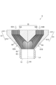
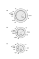
- FIG. 4 is a cross-sectional view of the tube of FIG. 5(a), 5(b), 5(c) and 5(d) are alternative cross-sectional views of the tube of FIG.
- FIG. 6 is a cross-sectional view of the first manifold portion of FIG.
- FIG. 7 is a cross-sectional view of the second manifold portion of FIG.
- FIG. 8 is a cross-sectional view showing a modified example of the tube.
- 9(a), 9(b), and 9(c) are alternative cross-sectional views of the tube of FIG.
- FIG. 1 is a perspective view showing the appearance of the heat exchanger 1 of this embodiment.
- the heat exchanger 1 receives steam 91 (first heat medium).
- the heat exchanger 1 receives a heat medium 92 (second heat medium).
- the heat medium 92 may be, for example, an organic solvent or acetone.
- the heat exchanger 1 removes heat from the received steam 91.
- some or all of the water contained in the steam 91 condenses.
- the condensed water is referred to as "condensate" in the following description.
- the heat exchanger 1 discharges condensate 93 as a result of the heat exchange.
- the heat exchanger 1 includes a steam inlet 11 (inlet), a condensate outlet 12 (outlet), a heat medium inlet 13, and a heat medium outlet 14.
- the steam inlet 11 is connected to, for example, a boiler.
- the steam inlet 11 receives steam 91 provided from the boiler.
- the steam inlet 11 is connected to a condensate outlet 12.
- the condensate outlet 12 discharges condensate 93.
- the condensate outlet 12 is connected to, for example, a flash tank.
- the condensate outlet 12 provides the condensate 93 to the flash tank.
- the heat medium inlet 13 is connected to, for example, a raw material tank.
- the heat medium inlet 13 receives the heat medium 92 before heat exchange provided from the raw material tank.
- the heat medium inlet 13 is connected to a heat medium outlet 14.
- the heat medium outlet 14 discharges the heat medium 92 after heat exchange.
- the heat medium outlet 14 is connected to, for example, a reactor.
- the heat medium outlet 14 provides the heat medium 92 after heat exchange to the reactor.
- the heat exchanger 1 is arranged so that the central axis L4 is parallel to the vertical direction.
- the central axis L4 is an axis that passes through the center of the housing body 4, which will be described later.
- This arrangement can be said to be “arranged vertically.”
- the steam inlet 11 is arranged vertically above the condensate outlet 12. Therefore, the steam 91 and condensate 93 move from top to bottom due to gravity.
- the heat medium inlet 13 is arranged vertically below the heat medium outlet 14. Therefore, the heat medium 92 moves from bottom to top against gravity.
- the direction in which the steam 91 and condensate 93 move along the central axis L4 is opposite to the direction in which the heat medium 92 moves. This type of flow is called “countercurrent” or "complete countercurrent.”
- the direction in which the heat medium 92 moves may be the same as the direction in which the steam 91 moves.
- the heat medium 92 may be introduced from a portion called the heat medium outlet 14, and the heat medium 92 may be discharged from a portion called the heat medium inlet 13. This type of flow is called "parallel flow.”
- the direction in which the heat medium 92 flows does not make any essential difference to the structure of the heat exchanger 1.
- the heat exchanger 1 of this embodiment can be used as either a counterflow type or a parallel flow type.
- FIG. 2 is a cross-sectional view of the heat exchanger 1 taken along line A1-A1 in FIG. 1.
- FIG. 3 is a cross-sectional view of the heat exchanger 1 taken along line A2-A2 in FIG. 1.
- FIG. 2 shows a cross-section of the heat exchanger 1 taken along a plane perpendicular to the central axis L4.
- FIG. 3 shows a cross-section of the heat exchanger 1 taken along a plane including the central axis L4.
- the heat exchanger 1 comprises, for example, a housing 2 and a plurality of tubes 3.
- the housing 2 comprises, for example, a housing main body 4, a first manifold section 5, and a second manifold section 6.
- the housing body 4 is, for example, a cylindrical member centered on the central axis L4.
- the housing body 4 extends along the axial direction D1 along which the central axis L4 runs.
- the axial direction D1 runs along the vertical direction.
- a heat medium inlet pipe section 41 is connected to the housing body 4.
- the heat medium inlet pipe section 41 is a tubular section including the heat medium inlet 13 described above.
- the heat medium inlet pipe section 41 extends, for example, in a direction inclined with respect to the central axis L4.
- a heat medium discharge pipe section 42 (see FIG. 1) is connected to the housing body 4.
- the heat medium discharge pipe section 42 is a tubular section including the heat medium outlet 14 described above.
- the heat medium discharge pipe section 42 extends, for example, in the same direction as the heat medium inlet pipe section 41.
- the housing body 4 includes a support 43 extending along the central axis L4 therein.
- the support 43 may be, for example, a cylinder centered on the central axis L4.
- a plurality of tubes 3 are arranged inside the housing body 4.
- Each of the plurality of tubes 3 is, for example, a cylindrical member centered on a central axis L3 extending along the axial direction D1.
- the central axis L4 is an axis passing through the center of the tube 3.
- the central axis L3 of the tube 3 extends, for example, parallel to the central axis L4 of the housing body 4.
- four tubes 3 are arranged around the support 43 at an arrangement angle of 90 degrees.
- the individual configurations of the tubes 3 may be, for example, identical to each other.
- the housing body 4 includes a housing inner surface 44 that surrounds the multiple tubes 3.
- the tubes 3 include a tube outer surface 31 that faces the housing inner surface 44.
- the tube outer surface 31 is separated from the housing inner surface 44.
- a gap G is formed between the tube outer surface 31 and the housing inner surface 44.
- the heat medium 92 received from the heat medium inlet pipe portion 41 reaches the heat medium outlet pipe portion 42 through the gap G between the tube outer surface 31 and the housing inner surface 44.
- the steam 91 introduced from the steam inlet 11 described above flows in the tubes 3.
- the steam 91 flowing through the multiple tubes 3 exchanges heat with the heat medium 92 flowing through the gap G outside the tubes 3. Heat is removed from the steam 91 while it flows through the tubes 3. As a result, a part or all of the steam 91 becomes condensed liquid 93.
- FIG. 3 of the four tubes 3, two tubes 3A and 3B are shown aligned in a direction D3 perpendicular to the axial direction D1.
- fins 35, 54, and 64 which will be described later, are omitted from FIG. 3.
- one of the two tubes 3A and 3B may be referred to as the "first tube 3A” and the other of the two tubes 3A and 3B may be referred to as the "second tube 3B.”
- the first tube 3A and the second tube 3B are disposed on either side of the central axis L4 of the housing body 4 in the direction D3.
- the first tube 3A and the second tube 3B are each simply referred to as the "tube 3.”
- the tube 3 includes a tube inner surface 34 extending along the axial direction D1 from a first end 32 to a second end 33.
- the first end 32 may be one end of the tube 3 along the axial direction D1.
- the second end 33 may be the other end of the tube 3 opposite the first end 32.
- the first end 32 is formed with an inlet 32a through which a portion of the steam 91 flows in.
- the inlet 32a may be, for example, a substantially circular opening.
- the second end 33 is formed with an outlet 33a through which the condensate 93 flows out.
- the outlet 33a may be, for example, a substantially circular opening.
- the area of the outlet 33a is, for example, smaller than the area of the inlet 32a.
- the area of the inlet 32a may be the area of an area surrounded by the tube inner surface 34 at the first end 32.
- the area of the outlet 33a may be the area of an area surrounded by the tube inner surface 34 at the second end 33.
- a plurality of fins 35 are formed on the tube inner surface 34.
- Each of the plurality of fins 35 is a protrusion rising from the tube inner surface 34 toward the central axis L3.
- the plurality of fins 35 are arranged at regular intervals along the circumferential direction D2 and extend linearly along the axial direction D1.
- the circumferential direction D2 is a direction along a ring centered on the central axis L3.
- the steam 91 and condensate 93 flowing through the tube 3 flow along the axial direction D1 from the inlet 32a to the outlet 33a. Therefore, it can be said that the plurality of fins 35 extend along the flow direction of the steam 91 and condensate 93.
- the plurality of fins 35 do not necessarily need to be formed on the tube inner surface 34.
- the tube inner surface 34 may be a smooth surface without protrusions.
- the surfaces of the multiple fins 35 are described as being configured as part of the tube inner surface 34.
- the tube inner surface 34 includes fin surfaces 34a, which are the surfaces of the multiple fins 35, and base surfaces 34b, which are the portions other than the fin surfaces 34a (see FIG. 5).
- the fin surfaces 34a are the portions of the tube inner surface 34 that protrude from the base surfaces 34b toward the central axis L3.
- the base surfaces 34b are the portions of the tube inner surface 34 that are connected to the base of the fin surfaces 34a, i.e., the portions other than the fin surfaces 34a.
- the tube inner surface 34 surrounds the flow path of the steam 91. In other words, the area surrounded by the tube inner surface 34 constitutes the flow path through which the steam 91 flows.
- FIG. 2 shows the flow path cross section F surrounded by the tube inner surface 34.
- the flow path cross section F is shown by hatching with a dot pattern.
- the flow path cross section F is the cross-sectional area surrounded by the tube inner surface 34 when the tube 3 is cut by a plane perpendicular to the central axis L3.
- the area of the flow path cross section F is defined as the area of the cross-sectional area surrounded by the tube inner surface 34, i.e., the "flow path cross-sectional area.”
- the tube 3 includes, for example, a first body P1, a second body P2, and a constricted portion P3.
- the constricted portion P3 is a central portion of the tube 3 between the inlet 32a and the outlet 33a.
- the first body P1 is a portion of the tube 3 that extends along the axial direction D1 between the inlet 32a and the constricted portion P3.
- the second body P2 is a portion of the tube 3 that extends along the axial direction D1 between the constricted portion P3 and the outlet 33a.
- the multiple fins 35 are formed on at least the tube inner surface 34 of the constricted portion P3. In the present disclosure, the multiple fins 35 are formed across the first body P1, the constricted portion P3, and the second body P2. In other words, the multiple fins 35 extend continuously on the tube inner surface 34 from the inlet 32a to the outlet 33a.
- the inner diameter of the constriction portion P3 becomes smaller as it is positioned closer to the outlet 33a in the axial direction D1.
- the tube inner surface 34 of the constriction portion P3 is a tapered surface that decreases in diameter as it approaches the outlet 33a in the axial direction D1.
- the inner diameter may be the inner diameter of the base surface 34b of the tube inner surface 34.
- FIG. 4 shows the first body region R1, the second body region R2, the first throttling region R31 (first region), and the second throttling region R32 (second region).
- the first body region R1 is a partial region of the first body P1 at any position along the axial direction D1.
- the second body region R2 is a partial region of the second body P2 at any position along the axial direction D1.
- the first throttling region R31 is a partial region of the throttling portion P3 at any position along the axial direction D1.
- the second throttling region R32 is a partial region of the throttling portion P3 located closer to the outlet 33a in the axial direction D1 than the first throttling region R31.
- FIG. 5 is a cross-sectional view showing the flow passage cross section F1 of the first body region R1.
- (b) of FIG. 5 is a cross-sectional view showing the flow passage cross section F31 of the first throttling region R31.
- (c) of FIG. 5 is a cross-sectional view showing the flow passage cross section F32 of the second throttling region R32.
- (d) of FIG. 5 is a cross-sectional view showing the flow passage cross section F2 of the second body region R2.
- the area of the flow passage cross section F32 of the second throttling region R32 is smaller than the area of the flow passage cross section F31 of the first throttling region R31. Therefore, from (b) and (c) of FIG. 5, it can be seen that the area of the flow passage cross section F of the throttling portion P3 decreases the closer it is to the outlet 33a in the axial direction D1.
- each fin 35 formed on the tube inner surface 34 decreases the closer it is to the outlet 33a in the axial direction D1.
- the height of the fin 35 is the radial distance from the base surface 34b to the tip of the fin surface 34a.
- the radial direction is perpendicular to the central axis L3.
- the height H32 of the fin 35 in the second constriction region R32 shown in Figure 5(c) is lower than the height H31 of the fin 35 in the first constriction region R31 shown in Figure 5(b).
- the thickness T32 of the second narrowing region R32 shown in FIG. 5(c) is equal to or greater than the thickness T31 of the first narrowing region R31 shown in FIG. 5(b).
- the thickness T32 of the second narrowing region R32 is the same as the thickness T31 of the first narrowing region R31.
- the thickness T (see FIG. 3) of the narrowing portion P3 is constant at each position along the axial direction D1.
- Thiickness T refers to the thickness of the tube 3 at any position along the axial direction D1, i.e., the distance between the tube outer surface 31 and the base surface 34b of the tube inner surface 34.
- the flow passage cross section F of the first body P1 is constant at each position along the axial direction D1.
- the flow passage cross section F1 of the first body region R1 shown in FIG. 5(a) is, for example, the same as the maximum value of the area of the flow passage cross section F of the constriction section P3.
- the maximum value of the area of the flow passage cross section F of the constriction section P3 is the area of the flow passage cross section F of the connection section P3a (see FIG. 4) of the constriction section P3 to the first body P1.
- the flow passage cross section F of the second body P2 is constant at each position along the axial direction D1.
- the minimum value of the area of the flow passage cross section F of the constriction section P3 is the area of the flow passage cross section F of the connection section P3b (see FIG. 4) of the constriction section P3 to the second body P2. Therefore, the area of the flow passage cross section F2 of the second body region R2 is smaller than the area of the flow passage cross section F1 of the first body region R1.
- each fin 35 formed in the first body portion P1 and the second body portion P2 is constant at each position along the axial direction D1.
- the height H1 of each fin 35 in the first body region R1 shown in FIG. 5(a) is, for example, the same as the maximum value of the height of each fin 35 in the constricted portion P3.
- the height H2 of each fin 35 in the second body region R2 shown in FIG. 5(b) is the same as the minimum value of the height of each fin 35 in the constricted portion P3. Therefore, the height H2 of each fin 35 in the second body region R2 is lower than the height H1 of each fin 35 in the first body region R1.
- the thickness T of each of the first body portion P1 and the second body portion P2 is the same as the thickness T of the constricted portion P3.
- the thickness T1 of the first body region R1 shown in FIG. 5(a), the thickness T31 of the first constricted region R31 shown in FIG. 5(b), the thickness T32 of the second constricted region R32 shown in FIG. 5(c), and the thickness T2 of the second body region R2 shown in FIG. 5(d) are all the same. Therefore, the thickness T (see FIG. 3) of the tube 3 is constant at each position along the axial direction D1 from the inlet 32a to the outlet 33a. In other words, the tube inner surface 34 and the tube outer surface 31 extend parallel to each other, and the distance between the base surface 34b of the tube inner surface 34 and the tube outer surface 31 is constant.
- the first throttling region R31 is taken as an example of the "first region” of the present disclosure
- the second throttling region R32 is taken as an example of the "second region” of the present disclosure.
- the regions other than the first throttling region R31 and the second throttling region R32 may be taken as the "first region” and the first throttling region R31, the second throttling region R32, or the second throttling region R2 may be taken as the "second region”.
- first throttling region R31 may be taken as the "first region” and the second throttling region R32 or the second throttling region R2 may be taken as the "second region", or the second throttling region R32 may be taken as the "first region” and the second throttling region R2 may be taken as the "second region”.
- the first manifold section 5 is a lid section arranged to close one end of the housing body 4.
- the first manifold section 5 is connected to the first ends 32 of the multiple tubes 3.
- the first manifold section 5 distributes steam 91 received from the steam inlet 11 and supplies it to each tube 3.
- the second manifold section 6 is a lid section arranged to close the other end of the housing body 4.
- the second manifold section 6 is connected to the second ends 33 of each tube 3.
- the second manifold section 6 joins the condensate 93 from each tube 3 and discharges it from the condensate outlet 12.
- FIG. 6 is a cross-sectional view showing the first manifold section 5.
- the first manifold section 5 includes the steam inlet 11 described above and a plurality of steam outlets 15 through which steam 91 flows from the steam inlet 11.
- the inner wall surface 53 of the first manifold section 5 extends from the steam inlet 11 to the plurality of steam outlets 15.
- the inner wall surface 53 surrounds the flow path of the steam 91 that flows from the steam inlet 11 to the plurality of steam outlets 15.
- the first manifold section 5 includes, for example, one inlet pipe section 51 including a steam inlet 11, and multiple branch pipe sections 52 each including multiple steam outlets 15.
- the steam inlet 11 is formed at the outer end of the inlet pipe section 51.
- the inlet pipe section 51 is a tubular section extending along the central axis L4.
- the inner end of the inlet pipe section 51 is connected to multiple branch pipe sections 52.
- Each branch pipe section 52 includes a connecting pipe section 521 extending in a direction inclined relative to the central axis L4, and a parallel pipe section 522 extending parallel to the central axis L4.
- the connecting pipe section 521 is a tubular section that is connected to the inner end of the inlet pipe section 51.
- the connecting pipe section 521 is disposed between the inlet pipe section 51 and the parallel pipe section 522, and connects the inlet pipe section 51 and the parallel pipe section 522.
- the parallel pipe section 522 is a tubular section that extends coaxially with the tube 3.
- the inner end of the parallel pipe section 522 is connected to the connecting pipe section 521.
- a steam outlet 15 is formed at the outer end of the parallel pipe section 522. Each steam outlet 15 is connected to the inlet 32a of each tube 3. Therefore, the first manifold section 5 can guide the steam 91 received from the steam inlet 11 from each steam outlet 15 to each tube 3.
- FIG. 6 shows a first branch pipe section 52A including a first steam outlet 15A (first outlet) and a second branch pipe section 52B including a second steam outlet 15B (second outlet) among the multiple branch pipe sections 52.
- the first branch pipe section 52A is connected to the inlet 32a (see FIG. 3) of the first tube 3A.
- the second branch pipe section 52B is connected to the inlet 32a (see FIG. 3) of the second tube 3B.
- a part 91A of the steam 91 that flows from the steam inlet 11 into the introduction pipe section 51 flows from the first steam outlet 15A to the first tube 3A through the first branch pipe section 52A.
- a part 91B of the remaining part of the steam 91 flows from the second steam outlet 15B to the second tube 3B through the second branch pipe section 52B.
- the other part of the remaining part of the steam 91 flows from the other steam outlet 15 to the other tube 3 through the other branch pipe section 52.
- a plurality of fins 35 extending along the flow direction of the steam 91 are formed on the inner wall surface 53 of each branch pipe section 52.
- the plurality of fins 35 extend along the direction in which the connecting pipe section 521 extends, i.e., a direction inclined with respect to the central axis L4.
- the plurality of fins 54 extend along the direction in which the parallel pipe section 522 extends, i.e., along the central axis L4.
- the height and spacing of the plurality of fins 54 formed on the inner wall surface 53 of each branch pipe section 52 may be the same as the height and spacing of the plurality of fins 35 formed on the first body section P1 of the tube 3, for example.
- Figure 7 is an enlarged cross-sectional view of the second manifold section 6 of Figure 3.
- the second manifold section 6 includes a plurality of condensate inlets 16 into which condensate 93 flows from the plurality of tubes 3, and the condensate outlet 12 described above.
- the inner wall surface 63 of the second manifold section 6 extends from the plurality of condensate inlets 16 to the condensate outlet 12.
- the inner wall surface 63 surrounds the flow path of the condensate 93 that flows from the plurality of condensate inlets 16 to the condensate outlet 12.
- the second manifold section 6 includes, for example, a plurality of branch pipe sections 61 each including a plurality of condensate inlets 16, and one discharge pipe section 62 including a condensate outlet 12.
- Each branch pipe section 61 includes a parallel pipe section 611 extending parallel to the central axis L4, and a connecting pipe section 612 extending in a direction inclined relative to the central axis L4.
- the parallel pipe section 611 is a tubular section extending coaxially with the tube 3.
- a condensate inlet 16 is formed at the outer end of the parallel pipe section 611.
- the connecting pipe section 612 is a tubular section connected to the inner end of the parallel pipe section 611.
- the connecting pipe section 612 is disposed between the parallel pipe section 611 and the discharge pipe section 62, and connects the parallel pipe section 611 and the discharge pipe section 62.
- the discharge pipe section 62 is a tubular section extending along the central axis L4.
- the inner end of the discharge pipe section 62 is connected to the connecting pipe section 612.
- the outer end of the discharge pipe section 62 is formed with a condensate outlet 12. Therefore, the second manifold section 6 can guide the condensate 93 discharged from each tube 3 to the outside through the condensate outlet 12.
- FIG. 7 shows, of the multiple branch pipe sections 61, a first branch pipe section 61A including a first condensate inlet 16A (first inlet) and a second branch pipe section 61B including a second condensate inlet 16B (second inlet).
- the first branch pipe section 61A is connected to the outlet 33a (see FIG. 3) of the first tube 3A.
- the second branch pipe section 61B is connected to the outlet 33a (see FIG. 3) of the second tube 3B.
- the condensate 93 that flows from the first tube 3A into the first branch pipe section 61A via the condensate inlet 16 passes through the discharge pipe section 62 and is discharged to the outside from the condensate outlet 12.
- the condensate 93 that flows from the second tube 3B into the second branch pipe section 61B via the condensate inlet 16 passes through the discharge pipe section 62 and is discharged to the outside from the condensate outlet 12.
- the condensate 93 that flows from the other tube 3 into the other branch pipe section 61 through the other condensate inlet 16 passes through the discharge pipe section 62 and is discharged to the outside from the condensate outlet 12.
- each branch pipe section 61 is formed with a plurality of fins 64 extending along the flow direction of the condensate 93.
- the plurality of fins 64 extend in the direction in which the parallel pipe section 611 extends, i.e., along the central axis L4.
- the plurality of fins 64 extend in the direction in which the connecting pipe section 612 extends, i.e., in a direction inclined relative to the central axis L4.
- the height and spacing of the plurality of fins 64 formed on the inner wall surface 63 of each branch pipe section 61 may be the same as, for example, the height and spacing of the plurality of fins 35 formed on the second body section P2 of the tube 3.
- Heat exchanger 1 is formed by integrally forming multiple tubes 3, a housing body 4, a first manifold section 5, and a second manifold section 6. There are no explicit boundaries such as joint surfaces between the various components. In other words, heat exchanger 1 is not obtained by manufacturing multiple tubes 3, a housing body 4, a first manifold section 5, and a second manifold section 6 as separate parts and then going through a process of combining them. Such a heat exchanger 1 can be manufactured by so-called three-dimensional modeling technology.
- a full condensation type heat exchanger is placed horizontally and condensation occurs outside the tubes.
- the baffle cut is vertical so that condensation does not accumulate inside the shell. If the baffle cut is horizontal, the baffle may act as a weir and cause condensation to accumulate. The area where condensation accumulates does not function as a condensation surface (heat transfer surface). Furthermore, the flow state of the medium may become unstable. If a full condensation type heat exchanger is placed horizontally and condensation occurs inside the tubes, the above considerations are not required. Furthermore, if a full condensation type heat exchanger is placed vertically and condensation occurs outside the tubes, the above considerations are not required.
- the inner diameter of the tubes 3 must be set appropriately so as not to be affected by the growth of a condensate film at the bottom of the tubes 3.
- it is desirable to set the flow rate of the medium so that a condensate film does not grow on the inner surface 34 of the tubes 3.
- design strategies that suppress the growth of the condensate film (thinning) are not often adopted.
- the heat exchanger 1 of the present disclosure solves the above-mentioned problems by providing the following advantageous effects.
- a heat medium 92 flows from bottom to top in the gap G outside the tube 3.
- Steam 91 is introduced into the heat exchanger 1 from the steam inlet 11.
- the steam 91 has a certain kinetic energy that can be defined by the pressure and flow rate.
- This steam 91 flows into the tube 3.
- the tube inner surface 34 is an area that is affected by the heat medium 92, and therefore functions as a heat transfer surface.
- the steam 91 that comes into contact with the tube inner surface 34 reaches its saturation limit as heat is removed, and condenses.
- the steam 91 present near the tube inner surface 34 also reaches its saturation limit as heat is removed, and condenses.
- condensed liquid is generated.
- the condensed liquid is, for example, water.
- the tube inner surface 34 Since the tube 3 is arranged so that the central axis L3 is aligned vertically, the tube inner surface 34 also extends vertically downward. Therefore, the condensate 93 condensed on the tube inner surface 34 moves vertically downward by the action of gravity and is discharged to the outside from the condensate outlet 12.
- the amount of condensate 93 that condenses increases toward the downstream side of the tube 3, so the water level of the condensate 93 that accumulates in the tube 3 increases. In other words, the area in contact with the condensate 93 gradually increases toward the downstream.
- the portion in contact with the condensate 93 does not function as a heat transfer surface for condensation. Therefore, the area that functions as a heat transfer surface tends to decrease toward the downstream side.
- the tube 3 includes a constriction section P3 in which the area of the flow passage cross section F decreases as it is positioned closer to the outlet 33a in the axial direction D1.
- the steam 91 flows through the tube 3
- the steam 91 passes through the constriction section P3, and the flow rate of the steam 91 increases.
- the condensate 93 generated in the tube 3 is dragged by the steam 91 flowing at high speed and flows toward the outlet 33a.
- the condensate 93 is quickly discharged to the outside of the tube 3 without stagnation in the tube 3, following the flow of the steam 91. Therefore, the tube inner surface 34 can continue to function as a heat transfer surface.
- the condensate 93 generated by condensation is unlikely to remain in the area that functions as a heat transfer surface.
- the condensate 93 does not impede heat transfer, and the decrease in efficiency of the heat exchanger 1 can be suppressed.
- the tube 3 includes the constriction portion P3
- a larger portion of the steam 91 can be in direct contact with the tube inner surface 34 while the steam 91 flows from the inlet 32a to the outlet 33a of the tube 3, compared to when the steam 91 flows through a tube 3 having a constant inner diameter.
- heat exchange between the steam 91 flowing through the tube 3 and the heat medium 92 flowing outside the tube 3 can be performed more efficiently. Therefore, in the heat exchanger 1 of the present disclosure, it is possible to increase the efficiency of heat exchange.
- the driving force for moving the condensate 93 through the tube 3 does not need to be gravity, and may be a driving force other than gravity.
- the heat exchanger 1 of the present disclosure can eliminate a liquid film that may form on the tube inner surface 34, which is the heat transfer surface, by utilizing the increase in the flow rate of the steam 91 at the constriction portion P3.
- the heat exchanger 1 of the present disclosure is equipped with a mechanism for actively eliminating the liquid film in this manner. As a result, it is possible to suppress a decrease in the effective heat transfer surface caused by the formation of a liquid film on the tube inner surface 34.
- the heat exchanger 1 of the present disclosure can promote heat exchange between the steam 91 and the heat medium 92 by having the steam 91 flow through the constriction portion P3.
- the heat exchanger 1 of the present disclosure can perform a complete countercurrent operation. And, since the heat exchanger 1 of the present disclosure flows the steam 91 and the condensate 93 through the relatively thin tube 3 including the constriction portion P3, it is also possible to suppress the retention of non-compressible gas.
- a plurality of fins 35 may be formed on the tube inner surface 34.
- the plurality of fins 35 may extend along the axial direction D1 or may be arranged along the circumferential direction D2.
- the area of the tube inner surface 34 functioning as a heat transfer surface i.e., the heat transfer area
- the condensate 93 can be made to flow in the axial direction D1 and be easily discharged to the outside of the tube 3. Therefore, in the above configuration, a larger heat transfer area can be secured while maintaining the function of the tube inner surface 34 as a heat transfer surface, so that the efficiency of heat exchange can be further improved.
- the multiple fins 35 may be formed at least on the tube inner surface 34 of the narrowed portion P3.
- the height of each of the multiple fins 35 from the tube inner surface 34 may be lower as it is located closer to the outlet 33a in the axial direction D1.
- the steam 91 flows toward the outlet 33a of the tube 3
- heat exchange between the steam 91 and the heat medium 92 outside the tube 3 progresses, so that the steam 91 flows near the outlet 33a after a lot of heat exchange. Therefore, in the vicinity of the outlet 33a, it is not necessary to make the heat transfer area larger than necessary to promote heat exchange.
- the height of each of the multiple fins 35 is lower as it is located closer to the outlet 33a in the axial direction D1.
- the volume of the tube 3 can be kept small, making it possible to reduce the material cost of the tube 3.
- the tube 3 may include a first body P1 extending along the axial direction D1 between the inlet 32a and the constricted portion P3, and a second body P2 extending along the axial direction D1 between the constricted portion P3 and the outlet 33a.
- the area of the flow passage cross section F at each position of the first body P1 along the axial direction D1 may be constant.
- the area of the flow passage cross section F at each position of the second body P2 along the axial direction D1 may be constant.
- the area of the flow passage cross section F of the second body P2 may be smaller than the area of the flow passage cross section F of the first body P1.
- the steam 91 flows through the tube 3 in the order of the first body P1, the constricted portion P3, and the second body P2, and is then discharged from the outlet 33a of the tube 3. Since the steam 91 flows through the second body P2 near the outlet 33a after a large amount of heat exchange has been performed, the area of the flow passage cross section F does not need to be reduced more than necessary in the second body P2 to promote heat exchange. In contrast, in the above configuration, the area of the flow passage cross section F of the second body P2 is constant, so that the area of the flow passage cross section F of the second body P2 can be prevented from being excessively small.
- the area of the flow passage cross section F of the first body P1 between the inlet 32a and the throttling portion P3 is constant. If the first body P1 is not provided and the throttling portion P3 extends from the inlet 32a of the tube 3, for example, the steam 91 may flow through the throttling portion P3 without condensing at all. In this case, the possibility of erosion (corrosion) by the steam 91 occurring on the tube inner surface 34 of the throttling portion P3 increases.
- the tube 3 may include a first throttling region R31 disposed at any position along the axial direction D1, and a second throttling region R32 disposed closer to the outlet 33a in the axial direction D1 than the first throttling region R31 and having a flow passage cross-sectional area F smaller than the flow passage cross-sectional area F of the first throttling region R31.
- the thickness T32 of the second throttling region R32 may be equal to or greater than the thickness T31 of the first throttling region R31. In this case, the flow velocity of the steam 91 flowing through the second throttling region R32 is higher than the flow velocity of the steam 91 flowing through the first throttling region R31.
- the second throttling region R32 erosion (corrosion) of the tube inner surface 34 is more likely to occur due to the condensate 93 than in the first throttling region R31.
- the thickness T32 of the second throttling region R32 is equal to or greater than the thickness T31 of the first throttling region R31, it is possible to suppress a situation in which the mechanical strength of the second throttling region R32 is reduced due to erosion.
- the thickness T of the tube 3 may be constant at each position along the axial direction D1 from the inlet 32a to the outlet 33a.
- the tube 3 can be easily manufactured using, for example, three-dimensional modeling technology.
- the tubes 3 may be formed integrally with the housing 2.
- the tubes 3 can be easily manufactured using, for example, three-dimensional modeling technology.
- the heat exchanger 1 may include a first tube 3A and a second tube 3B.
- the first tube 3A and the second tube 3B may extend along the axial direction D1, or may be aligned along the direction D3.
- the amount of steam 91 can be increased, so that heat exchange between the steam 91 and the heat medium 92 can be performed even more efficiently.
- the housing may include a first manifold section 5 that distributes the steam 91 and supplies it to the first tube 3A and the second tube 3B.
- a plurality of fins 54 extending along the flow direction of the steam 91 may be formed on the inner wall surface 53 of the first manifold section 5.
- the area of the inner wall surface 53 of the first manifold section 5 that can function as a heat transfer surface, i.e., the heat transfer area can be secured to be larger than when a plurality of fins 54 are not formed on the inner wall surface 53. This makes it possible to further improve the efficiency of heat exchange.
- the steam 91 flowing in from the steam inlet 11 can flow more easily in the flow direction than when a plurality of fins 54 extend along a direction perpendicular to the flow direction.
- the condensate 93 formed in the tube 3 can be more easily discharged to the outside.
- the housing 2 may include a second manifold section 6 that joins and discharges the steam 91 from the first tube 3A and the second tube 3B.
- a plurality of fins 64 extending along the flow direction of the steam 91 may be formed on the inner wall surface 63 of the second manifold section 6.
- the area of the inner wall surface 63 of the second manifold section 6 that can function as a heat transfer surface, i.e., the heat transfer area can be secured to be large, compared to when a plurality of fins 64 are not formed on the inner wall surface 63. This makes it possible to further improve the efficiency of heat exchange.
- the condensate 93 that has flowed into the first condensate inlet 16A and the second condensate inlet 16B can be made to flow in the flow direction and be more easily discharged to the outside from the condensate outlet 12, compared to when a plurality of fins 64 extend along a direction perpendicular to the flow direction. This makes it possible to prevent the condensate 93 from the first tube 3A and the second tube 3B from accumulating in the second manifold section 6.
- FIG. 8 is a cross-sectional view showing a modified example of the tube.
- the thickness T of the tube 3 is constant.
- the thickness TA of the tube 300 shown in FIG. 8 changes.
- Thiickness TA means the thickness of the tube 300 at any position along the axial direction D1, i.e., the distance between the tube outer surface 31 and the base surface 34b of the tube inner surface 34.
- the tube 300 has a constricted portion P3A and a second body portion P2A instead of the constricted portion P3A and the second body portion P2A.
- the thickness TA of the constricted portion P3A becomes thicker as it is located closer to the outlet 33a in the axial direction D1.
- the thickness TA of the second body portion P2A is the same as the maximum value of the thickness TA of the connection portion P3b of the constricted portion P3A.
- FIG. 8 shows a first throttling region R31A (first region), a second throttling region R32A (second region), and a second body region R2A.
- the first throttling region R31A is a partial region of the throttling portion P3A at any position along the axial direction D1.
- the second throttling region R32A is a partial region of the throttling portion P3A located closer to the outlet 33a in the axial direction D1 than the first throttling region R31A.
- the second body region R2A is a partial region of the second body P2A at any position along the axial direction D1.
- FIG. 9 is a cross-sectional view showing the flow path cross section F31A of the first throttling region R31A.
- (b) of Figure 9 is a cross-sectional view showing the flow path cross section F32A of the second throttling region R32A.
- (c) of Figure 9 is a cross-sectional view showing the flow path cross section F2A of the second body region R2A.
- the thickness T32A of the second throttling region R32A is thicker than the thickness T31A of the first throttling region R31A.
- the same effect as in the above embodiment can be obtained. Furthermore, when the thickness T32A of the second throttling region R32A is thicker than the thickness T31A of the first throttling region R31A as in the tube 300, the occurrence of a decrease in the mechanical strength of the second throttling region R32A due to erosion can be more reliably suppressed.
- the regions other than the first throttling region R31A and the second throttling region R32A may be regarded as the "first region” and the "second region".
- the first throttling region R31A may be regarded as the "first region”
- the second throttling region R32A or the second body region R2A may be regarded as the "second region”
- the second throttling region R32A may be regarded as the "first region”
- the second body region R2A may be regarded as the "second region”.
- the heat exchanger disclosed herein can also be configured as shown below, for example.
- the present disclosure is [1] "a tube used in a heat exchanger, characterized in that the cross-sectional area, cut vertically in the direction of the fluid flow in the flow path, decreases from one end of the flow path to the other end of the flow path.”
- the present disclosure is [2] "the heat exchanger described in [1] above, characterized in that the inside of the flow path has a fin structure.”
- the present disclosure is [3] "a heat exchanger as described in [1] or [2] above, in which the thickness of the portion where the cross-sectional area of the flow path is reduced is equal to or greater than the thickness of the portion where the cross-sectional area of the flow path is greater than the reduced cross-sectional area.”
- the present disclosure is [4] "A heat exchanger according to any one of [1] to [3] above, in which the thickness of the tube is constant throughout the tube.”
- the present disclosure is [5] "a heat exchanger according to any one of [1] to [3] above, characterized in that the thickness of the portion where the cross-sectional area of the flow path is reduced is greater than the thickness of the portion where the cross-sectional area of the flow path is greater than the reduced cross-sectional area.”
- the present disclosure is [6] "A heat exchanger according to any one of [1] to [5] above, characterized in that the tube is manufactured by a 3D printer.”
- the present disclosure is [7] "A heat exchanger characterized by including a plurality of tubes described in any one of [1] to [6] above.”
- 1...heat exchanger 2...housing, 3, 3A, 3B, 300...tubes, 3A...first tube, 3B...second tube, 5...first manifold section, 6...second manifold section, 11...steam inlet (inlet), 12...condensate outlet (outlet), 15A...first steam outlet (first outlet), 15B...second steam outlet (second outlet), 16A...first condensate inlet (first inlet), 16B...second condensate inlet (second inlet), 31...tube outer surface, 32...first end, 32a...inlet, 33...second end, 33a...outlet, 34...tube inner surface, 35, 54, 64...fins, 44...casing inner surface, 53, 63...inner wall surface, 91...steam (first heat medium), 92...heat medium (second heat medium), D1...axial direction, D2...circumferential direction, D3...direction, L3...center axis, P1...first body, P2, P2A...second body, P3, P3A
Landscapes
- Engineering & Computer Science (AREA)
- Physics & Mathematics (AREA)
- Thermal Sciences (AREA)
- Mechanical Engineering (AREA)
- General Engineering & Computer Science (AREA)
- Geometry (AREA)
- Heat-Exchange Devices With Radiators And Conduit Assemblies (AREA)
Priority Applications (2)
| Application Number | Priority Date | Filing Date | Title |
|---|---|---|---|
| JP2025539008A JPWO2025032735A1 (https=) | 2023-08-08 | 2023-08-08 | |
| PCT/JP2023/028978 WO2025032735A1 (ja) | 2023-08-08 | 2023-08-08 | 熱交換器 |
Applications Claiming Priority (1)
| Application Number | Priority Date | Filing Date | Title |
|---|---|---|---|
| PCT/JP2023/028978 WO2025032735A1 (ja) | 2023-08-08 | 2023-08-08 | 熱交換器 |
Publications (1)
| Publication Number | Publication Date |
|---|---|
| WO2025032735A1 true WO2025032735A1 (ja) | 2025-02-13 |
Family
ID=94534392
Family Applications (1)
| Application Number | Title | Priority Date | Filing Date |
|---|---|---|---|
| PCT/JP2023/028978 Pending WO2025032735A1 (ja) | 2023-08-08 | 2023-08-08 | 熱交換器 |
Country Status (2)
| Country | Link |
|---|---|
| JP (1) | JPWO2025032735A1 (https=) |
| WO (1) | WO2025032735A1 (https=) |
Cited By (1)
| Publication number | Priority date | Publication date | Assignee | Title |
|---|---|---|---|---|
| WO2026048966A1 (ja) * | 2024-08-29 | 2026-03-05 | 株式会社Mari&Ken | 熱交換器及び冷凍サイクル装置 |
Citations (6)
| Publication number | Priority date | Publication date | Assignee | Title |
|---|---|---|---|---|
| JPS57132971U (https=) * | 1981-02-16 | 1982-08-19 | ||
| JP2000283663A (ja) * | 1999-03-30 | 2000-10-13 | Toyota Motor Corp | 排気冷却装置 |
| JP2007285264A (ja) * | 2006-04-19 | 2007-11-01 | Toyota Motor Corp | 熱交換器 |
| JP2009162396A (ja) * | 2007-12-28 | 2009-07-23 | Showa Denko Kk | 二重管式熱交換器 |
| US20150068502A1 (en) * | 2013-09-11 | 2015-03-12 | GM Global Technology Operations LLC | Exhaust gas recirculation cooler and system |
| JP2018519490A (ja) * | 2015-07-10 | 2018-07-19 | コンフラックス テクノロジー ピーティーワイ リミテッドConflux Technology Pty Ltd | 熱交換器 |
-
2023
- 2023-08-08 JP JP2025539008A patent/JPWO2025032735A1/ja active Pending
- 2023-08-08 WO PCT/JP2023/028978 patent/WO2025032735A1/ja active Pending
Patent Citations (6)
| Publication number | Priority date | Publication date | Assignee | Title |
|---|---|---|---|---|
| JPS57132971U (https=) * | 1981-02-16 | 1982-08-19 | ||
| JP2000283663A (ja) * | 1999-03-30 | 2000-10-13 | Toyota Motor Corp | 排気冷却装置 |
| JP2007285264A (ja) * | 2006-04-19 | 2007-11-01 | Toyota Motor Corp | 熱交換器 |
| JP2009162396A (ja) * | 2007-12-28 | 2009-07-23 | Showa Denko Kk | 二重管式熱交換器 |
| US20150068502A1 (en) * | 2013-09-11 | 2015-03-12 | GM Global Technology Operations LLC | Exhaust gas recirculation cooler and system |
| JP2018519490A (ja) * | 2015-07-10 | 2018-07-19 | コンフラックス テクノロジー ピーティーワイ リミテッドConflux Technology Pty Ltd | 熱交換器 |
Cited By (1)
| Publication number | Priority date | Publication date | Assignee | Title |
|---|---|---|---|---|
| WO2026048966A1 (ja) * | 2024-08-29 | 2026-03-05 | 株式会社Mari&Ken | 熱交換器及び冷凍サイクル装置 |
Also Published As
| Publication number | Publication date |
|---|---|
| JPWO2025032735A1 (https=) | 2025-02-13 |
Similar Documents
| Publication | Publication Date | Title |
|---|---|---|
| CN108463682B (zh) | U形管热交换器 | |
| US8602089B2 (en) | Heat exchanger apparatus for accommodating thermal and/or pressure transients | |
| JP4314058B2 (ja) | 浮動ヘッドを有する改良された熱交換器 | |
| US20160018168A1 (en) | Angled Tube Fins to Support Shell Side Flow | |
| US8418753B2 (en) | Heat exchange tube | |
| JP7671342B2 (ja) | 垂直ロッドバッフル熱交換器のシステムおよび方法 | |
| CN108351175A (zh) | 热交换器 | |
| WO2025032735A1 (ja) | 熱交換器 | |
| RU2566767C2 (ru) | Химический реактор с пластинчатым теплообменником | |
| EP3705829B1 (en) | Heat exchanger | |
| KR101967273B1 (ko) | 쉘 앤드 튜브 타입 열교환기 | |
| CN105580087A (zh) | 蒸汽发生器以及在蒸汽发生器内抗振地固定换热器管的方法 | |
| US12460871B2 (en) | Heat exchanger | |
| US5894883A (en) | Shell and tube heat exchanger | |
| WO2025004181A1 (ja) | 熱交換器 | |
| JP6397267B2 (ja) | 熱交換器 | |
| US6866093B2 (en) | Isolation and flow direction/control plates for a heat exchanger | |
| JP6139083B2 (ja) | 軸流排気式復水器 | |
| JP6326430B2 (ja) | 復水器 | |
| JP6871402B2 (ja) | シェルアンドチューブ式機器のための保護装置 | |
| US20260022901A1 (en) | Sieve element of a tubular heat exchanger and its use in a tubular heat exchanger | |
| JP7311655B2 (ja) | 熱交換器 | |
| JPH05231793A (ja) | 平行流形熱交換器 | |
| JP6247541B2 (ja) | 多管式貫流ボイラ | |
| JP7621917B2 (ja) | 熱交換器 |
Legal Events
| Date | Code | Title | Description |
|---|---|---|---|
| 121 | Ep: the epo has been informed by wipo that ep was designated in this application |
Ref document number: 23948455 Country of ref document: EP Kind code of ref document: A1 |
|
| ENP | Entry into the national phase |
Ref document number: 2025539008 Country of ref document: JP Kind code of ref document: A |
|
| WWE | Wipo information: entry into national phase |
Ref document number: 2025539008 Country of ref document: JP |
|
| NENP | Non-entry into the national phase |
Ref country code: DE |