WO2025022706A1 - 物体検知システム、物体検知装置、および物体検知方法 - Google Patents
物体検知システム、物体検知装置、および物体検知方法 Download PDFInfo
- Publication number
- WO2025022706A1 WO2025022706A1 PCT/JP2024/009242 JP2024009242W WO2025022706A1 WO 2025022706 A1 WO2025022706 A1 WO 2025022706A1 JP 2024009242 W JP2024009242 W JP 2024009242W WO 2025022706 A1 WO2025022706 A1 WO 2025022706A1
- Authority
- WO
- WIPO (PCT)
- Prior art keywords
- object detection
- area
- point cloud
- cloud data
- accumulated
- Prior art date
- Legal status (The legal status is an assumption and is not a legal conclusion. Google has not performed a legal analysis and makes no representation as to the accuracy of the status listed.)
- Pending
Links
Images




Classifications
-
- G—PHYSICS
- G01—MEASURING; TESTING
- G01S—RADIO DIRECTION-FINDING; RADIO NAVIGATION; DETERMINING DISTANCE OR VELOCITY BY USE OF RADIO WAVES; LOCATING OR PRESENCE-DETECTING BY USE OF THE REFLECTION OR RERADIATION OF RADIO WAVES; ANALOGOUS ARRANGEMENTS USING OTHER WAVES
- G01S17/00—Systems using the reflection or reradiation of electromagnetic waves other than radio waves, e.g. lidar systems
- G01S17/02—Systems using the reflection of electromagnetic waves other than radio waves
- G01S17/06—Systems determining position data of a target
- G01S17/46—Indirect determination of position data
-
- G—PHYSICS
- G01—MEASURING; TESTING
- G01S—RADIO DIRECTION-FINDING; RADIO NAVIGATION; DETERMINING DISTANCE OR VELOCITY BY USE OF RADIO WAVES; LOCATING OR PRESENCE-DETECTING BY USE OF THE REFLECTION OR RERADIATION OF RADIO WAVES; ANALOGOUS ARRANGEMENTS USING OTHER WAVES
- G01S17/00—Systems using the reflection or reradiation of electromagnetic waves other than radio waves, e.g. lidar systems
- G01S17/88—Lidar systems specially adapted for specific applications
- G01S17/89—Lidar systems specially adapted for specific applications for mapping or imaging
Definitions
- the present invention relates to an object detection system based on point cloud data acquired by scanning a monitoring area.
- FIG. 1 shows an example of the configuration of an object detection system.
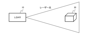
- Figure 2 shows an image of how the object detection system works.
- the object detection system in FIG. 1 includes a LiDAR 10 and an object detection server 20.
- the LiDAR 10 acquires point cloud data representing the three-dimensional position and shape of an object 30 present in the monitoring range by scanning and irradiating a laser light onto the monitoring range and measuring the arrival time of the reflected light.
- the point cloud data acquired by the LiDAR 10 is transmitted to the object detection server 20 via a network NW.
- the object detection server 20 executes an object detection process to detect an object 30 present in the monitoring range based on the point cloud data received from the LiDAR 10.
- the resolution of the laser light emitted from a LiDAR is determined by the LiDAR's irradiation pattern and the individual LiDAR.
- the higher the resolution of the laser light the higher the density of the point cloud data that can be acquired, making it possible to detect smaller or more distant objects.
- the resolution of the laser light is low, the density of the point cloud data that can be acquired will be low, making it difficult to detect small or distant objects. This is because conventional object detection systems detect objects using one frame of point cloud data acquired by LiDAR at a time.
- Figure 3 shows an example of one frame of point cloud data obtained by LiDAR for an object.
- the density of the point cloud data is low, so the object cannot be accurately identified.
- it has been considered to accumulate and overlay multiple frames of point cloud data before processing (see, for example, Non-Patent Document 1).
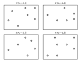
- Figure 4 shows an example of point cloud data from the first to fourth frames obtained for an object by LiDAR.
- the point cloud data obtained by LiDAR is acquired with a slight shift in the coordinates of the point cloud data in successive frames, as shown in Figure 4, even when the object is stationary. Therefore, by accumulating and overlaying point cloud data from multiple frames, as shown in Figure 5, the density of the point cloud data can be artificially increased, allowing for more accurate object detection and discrimination.
- the accumulation (overlay) of point cloud data described above is effective for stationary objects (hereafter referred to as "stationary objects"), but is less effective for moving objects, especially objects that move a lot (hereafter referred to as “moving objects”).
- stationary objects stationary objects
- moving objects moving objects
- This problem can be addressed by using high-performance (high-resolution) LiDAR or by increasing the number of LiDAR units installed, but this is hardware-dependent and expensive.
- the present invention was made in consideration of the above-mentioned conventional circumstances, and aims to provide a mechanism for object detection based on point cloud data acquired by scanning a monitoring range, capable of effectively detecting both stationary and moving objects.
- an object detection system is configured as follows. That is, in an object detection system including a point cloud data acquisition device that scans a monitoring range to acquire point cloud data, and an object detection device that executes object detection processing based on the point cloud data acquired by the point cloud data acquisition device, the object detection device accumulates point cloud data for each area within the monitoring range by the number of accumulation frames set for that area, in accordance with the setting of the number of accumulation frames for each area into which the monitoring range is divided, and executes the object detection processing based on the accumulated point cloud data.
- the number of accumulated frames for each area can be set to a value according to the expected speed of the object to be detected in each area.
- the number of accumulated frames for each area can be set to a different value between the time period when the presence of an object to be detected in each area is expected and other time periods.
- the object detection device can be configured to re-execute the object detection process for an area in which an object has been detected by the object detection process, based on point cloud data that has accumulated a number of accumulated frames that is greater than the number set for that area.
- An object detection device is configured as follows. That is, in an object detection device that performs object detection processing based on point cloud data acquired by scanning a monitoring range, the device accumulates point cloud data for each area within the monitoring range by the number of accumulated frames set for that area according to the setting of the number of accumulated frames for each area into which the monitoring range is divided, and performs the object detection processing based on the accumulated point cloud data.
- An object detection method is configured as follows. That is, in the object detection method based on point cloud data acquired by scanning a monitoring range, an object detection device accumulates point cloud data for each area within the monitoring range by the number of accumulated frames set for that area in accordance with the setting of the number of accumulated frames for each area into which the monitoring range is divided, and performs object detection processing based on the accumulated point cloud data.
- the present invention provides a mechanism for object detection based on point cloud data acquired by scanning a monitoring range, which can effectively detect both stationary and moving objects.
- FIG. 1 is a diagram illustrating an example of the configuration of an object detection system.
- FIG. 2 is a diagram illustrating an operation image of the object detection system illustrated in FIG. 1 .
- FIG. 2 is a diagram showing an example of one frame of point cloud data obtained regarding an object.
- FIG. 2 is a diagram showing an example of point cloud data of the first to fourth frames obtained regarding an object.
- FIG. 13 is a diagram showing an example of point cloud data obtained by overlapping four frames.
- FIG. 2 is a diagram showing an example of division of a monitoring range in the proposed method.
- FIG. 11 is a diagram showing an example of data on the number of accumulated frames by area in the proposed method.
- FIG. 2 is a diagram illustrating an example of a processing flow in the proposed method.
- the general configuration of an object detection system according to one embodiment of the present invention is the same as the object detection system shown in FIG. 1. That is, the object detection system of this example has a LiDAR 10, which is an example of a point cloud data acquisition device according to the present invention, and an object detection server 20, which is an example of an object detection device according to the present invention.
- a LiDAR 10 which is an example of a point cloud data acquisition device according to the present invention
- an object detection server 20 which is an example of an object detection device according to the present invention.
- LiDAR10 acquires point cloud data representing the three-dimensional position and shape of object 30 present within the monitoring range by scanning and irradiating the monitoring range with laser light and measuring the arrival time of the reflected light.
- the point cloud data acquired by LiDAR10 is transmitted to object detection server 20 via network NW.
- object detection server 20 executes object detection processing to detect object 30 present within the monitoring range.
- the point cloud data is processed using background subtraction to determine the size, shape, etc. of the detected object, and the detected object is identified based on the results.
- the detected object may be identified by matching with previously registered object shapes or by an AI model that has learned the object shape.
- LiDAR 10 instead of LiDAR 10, other point cloud data acquisition devices such as 3D sensors capable of acquiring point cloud data representing the three-dimensional position and shape of objects present in the monitoring range may be used.
- the object detection server 20 may execute object detection processing based on the point cloud data acquired by each LiDAR 10.
- the object detection server 20 may be realized, for example, by a computer equipped with hardware resources such as a processor and memory, and may be configured to read programs related to each function according to the present invention from the memory and execute them by the processor.
- the object detection server 20 may be realized by one computer, or by multiple computers connected to each other so that they can communicate with each other.
- the object detection server 20 divides the monitoring range into multiple areas and executes object detection processing with a different number of accumulated frames for each area. For example, as shown in FIG. 6, the monitoring range is divided into an air area whose main purpose is to detect stationary objects (flying objects caught on utility poles or electric wires) and a ground area whose main purpose is to detect moving objects (passing people and vehicles).
- FIG. 7 shows an example of area-specific accumulated frame number data used for the above control.
- Such area-specific accumulated frame number data is stored in the internal memory of the object detection server 20 or in an external device accessible to the object detection server 20.
- the area-specific accumulated frame number data may be set manually by a user of the object detection system, or may be set automatically by a device such as the object detection server 20 according to the distribution of stationary and moving objects analyzed from past point cloud data.
- the object detection server 20 accumulates point cloud data for each area within the monitoring range by the number of accumulated frames set for that area according to the area-specific accumulated frame count data described above, and performs object detection processing based on the accumulated point cloud data.
- the object detection server 20 will perform object detection processing for the sky area based on point cloud data accumulated and superimposed over four frames, and for the ground area based on one frame of point cloud data.
- FIG. 8 shows an example of a processing flow in the proposed method.
- the object detection server 20 initializes (sets to 0) the frame counter for each area and initializes (clears) the accumulated point cloud data for each area (step S11).
- the object detection server 20 receives one frame of point cloud data from the LiDAR 10 (step S12), it performs the following processing (steps S13 to S17) for each area.
- step S13 the frame counter of area n (where 1 ⁇ n ⁇ number of areas) is incremented (added by 1) (step S13), and the corresponding portion of the received point cloud data is added to the accumulated point cloud data of area n (step S14).
- step S15 it is determined whether the frame counter of area n has reached the accumulated frame number (step S15). If the frame counter of area n has reached the accumulated frame number (step S15; Yes), object detection processing is performed based on the accumulated point cloud data of area n (step S16), and the frame counter and accumulated point cloud data of area n are reset (step S17), and processing of the next area is started.
- step S15 if the frame counter of area n has not reached the accumulated frame number (step S15; Yes), processing of steps S16 to S17 is not performed, and processing of the next area is started. If processing of all areas is completed, the system waits until the reception of the next frame of point cloud data (step S12).
- object detection processing in the sky area is performed every four frames, but by storing point cloud data for the number of accumulated frames as history, it is also possible to perform object detection processing for each frame (each time point cloud data is received from LiDAR) by overlaying the point cloud data from the past four frames.
- the object detection system of this example includes LiDAR 10 that scans the monitoring range to acquire point cloud data, and object detection server 20 that executes object detection processing based on the point cloud data acquired by LiDAR 10.
- Object detection server 20 accumulates point cloud data for each area within the monitoring range by the number of accumulation frames set for that area according to the setting of the number of accumulation frames for each area into which the monitoring range is divided, and executes object detection processing based on the accumulated point cloud data.
- object detection processing can be performed based on point cloud data accumulated and overlaid over four frames
- object detection processing can be performed based on point cloud data for one frame.
- flying objects caught on utility poles or power lines can be detected with high accuracy
- in the ground area people and vehicles passing by can be detected with high accuracy.
- this can be achieved through ingenuity in software rather than hardware, more advanced detection is possible while keeping costs down for the entire system.
- the number of accumulated frames in the air area, where the main purpose is to detect stationary objects is set to 4, and the number of accumulated frames in the ground area, where the main purpose is to detect moving objects, is set to 1, but this is merely an example.
- the number of accumulated frames for each area may be set to a value according to the expected speed of the object to be detected in each area.
- the number of accumulated frames in an area, where the main purpose is to detect slow-moving moving objects may be set to 2
- the number of accumulated frames in an area, where the main purpose is to detect fast-moving moving objects may be set to 1.
- the number of accumulated frames for each area may be set to a different value depending on the time of day when the presence of an object to be detected in each area is expected and other time of day.
- the number of accumulated frames may be set to a low value during time periods when pedestrians are expected to pass by, and to a high value during time periods when pedestrians are not expected to pass by.
- the number of accumulated frames for each area may be set to a value according to the LiDAR sampling period.
- the number of accumulated frames may be increased when the LiDAR sampling period is short, and decreased when the sampling period is long.
- the number of accumulated frames for each area may be set to a value according to the urgency of detection in each area (degree of need for immediate detection).
- the number of accumulated frames may be increased in areas where the urgency of detection is low, and decreased in areas where the urgency of detection is high.
- the monitoring range is divided into two areas, but it may be divided into three or more areas.
- it may be divided into an overhead area, an area where passengers walk (platform area), and an area where trains run (railroad track area), and a different number of accumulated frames may be set for each area.
- the object detection server 20 may re-execute the object detection process for an area in which an object has been detected by the object detection process, based on point cloud data that has accumulated a number of frames greater than the number set for that area. For example, if an object is detected by executing the object detection process for a ground area based on one frame of point cloud data, the object detection process is re-executed for the ground area based on four frames of point cloud data. This makes it possible to further improve the accuracy of object detection.
- the present invention can be provided not only as the devices described above or as systems composed of these devices, but also as methods executed by these devices, programs for implementing the functions of these devices using a processor, and storage media for storing such programs in a computer-readable format.
- the present invention can be used in an object detection system based on point cloud data acquired by scanning a monitoring area.
Landscapes
- Physics & Mathematics (AREA)
- Engineering & Computer Science (AREA)
- Electromagnetism (AREA)
- Computer Networks & Wireless Communication (AREA)
- General Physics & Mathematics (AREA)
- Radar, Positioning & Navigation (AREA)
- Remote Sensing (AREA)
- Optical Radar Systems And Details Thereof (AREA)
Abstract
Description
物体検知サーバ20はまず、エリア別のフレームカウンタの初期化(0をセット)およびエリア別の蓄積点群データの初期化(クリア)を行う(ステップS11)。その後、物体検知サーバ20は、LiDAR10から1フレーム分の点群データを受信すると(ステップS12)、各エリアに対して以下の処理(ステップS13~S17)を行う。
Claims (6)
- 監視範囲を走査して点群データを取得する点群データ取得装置と、
前記点群データ取得装置により取得された点群データに基づいて物体検知処理を実行する物体検知装置とを備えた物体検知システムにおいて、
前記物体検知装置は、前記監視範囲を区分したエリア別の蓄積フレーム数の設定に従って、前記監視範囲内の各エリアの点群データを該エリアに設定された蓄積フレーム数分ずつ蓄積し、蓄積された点群データに基づいて前記物体検知処理を実行することを特徴とする物体検知システム。 - 請求項1に記載の物体検知システムにおいて、
前記エリア別の蓄積フレーム数は、各エリアでの検知目標となる物体の想定速度に応じた値が設定されることを特徴とする物体検知システム。 - 請求項1に記載の物体検知システムにおいて、
前記エリア別の蓄積フレーム数は、各エリアでの検知目標となる物体の存在が想定される時間帯と他の時間帯とで異なる値が設定されることを特徴とする物体検知システム。 - 請求項1に記載の物体検知システムにおいて、
前記物体検知装置は、前記物体検知処理によって物体が検知されたエリアに対し、該エリアに対する設定より多い蓄積フレーム数分を蓄積した点群データに基づいて、前記物体検知処理を実行し直すことを特徴とする物体検知システム。 - 監視範囲を走査して取得される点群データに基づいて物体検知処理を実行する物体検知装置において、
前記監視範囲を区分したエリア別の蓄積フレーム数の設定に従って、前記監視範囲内の各エリアの点群データを該エリアに設定された蓄積フレーム数分ずつ蓄積し、蓄積された点群データに基づいて前記物体検知処理を実行することを特徴とする物体検知装置。 - 監視範囲を走査して取得される点群データに基づく物体検知方法において、
物体検知装置が、前記監視範囲を区分したエリア別の蓄積フレーム数の設定に従って、前記監視範囲内の各エリアの点群データを該エリアに設定された蓄積フレーム数分ずつ蓄積し、蓄積された点群データに基づいて物体検知処理を実行することを特徴とする物体検知方法。
Priority Applications (2)
| Application Number | Priority Date | Filing Date | Title |
|---|---|---|---|
| GB2518542.2A GB2644516A (en) | 2023-07-26 | 2024-03-11 | Object detection system, object detection device, and object detection method |
| JP2025535560A JPWO2025022706A1 (ja) | 2023-07-26 | 2024-03-11 |
Applications Claiming Priority (2)
| Application Number | Priority Date | Filing Date | Title |
|---|---|---|---|
| JP2023121949 | 2023-07-26 | ||
| JP2023-121949 | 2023-07-26 |
Publications (1)
| Publication Number | Publication Date |
|---|---|
| WO2025022706A1 true WO2025022706A1 (ja) | 2025-01-30 |
Family
ID=94374640
Family Applications (1)
| Application Number | Title | Priority Date | Filing Date |
|---|---|---|---|
| PCT/JP2024/009242 Pending WO2025022706A1 (ja) | 2023-07-26 | 2024-03-11 | 物体検知システム、物体検知装置、および物体検知方法 |
Country Status (3)
| Country | Link |
|---|---|
| JP (1) | JPWO2025022706A1 (ja) |
| GB (1) | GB2644516A (ja) |
| WO (1) | WO2025022706A1 (ja) |
Citations (4)
| Publication number | Priority date | Publication date | Assignee | Title |
|---|---|---|---|---|
| CN111045017A (zh) * | 2019-12-20 | 2020-04-21 | 成都理工大学 | 一种激光和视觉融合的巡检机器人变电站地图构建方法 |
| JP2021196195A (ja) * | 2020-06-10 | 2021-12-27 | パナソニックIpマネジメント株式会社 | 処理装置、処理方法、プログラム、及び、レーダ装置 |
| JP2022112828A (ja) * | 2021-01-22 | 2022-08-03 | 凸版印刷株式会社 | 距離画像撮像装置及び距離画像撮像方法 |
| US20230230368A1 (en) * | 2020-05-25 | 2023-07-20 | Sony Semiconductor Solutions Corporation | Information processing apparatus, information processing method, and program |
Family Cites Families (1)
| Publication number | Priority date | Publication date | Assignee | Title |
|---|---|---|---|---|
| JP7361496B2 (ja) * | 2019-05-24 | 2023-10-16 | 三菱電機株式会社 | 監視装置 |
-
2024
- 2024-03-11 WO PCT/JP2024/009242 patent/WO2025022706A1/ja active Pending
- 2024-03-11 JP JP2025535560A patent/JPWO2025022706A1/ja active Pending
- 2024-03-11 GB GB2518542.2A patent/GB2644516A/en active Pending
Patent Citations (4)
| Publication number | Priority date | Publication date | Assignee | Title |
|---|---|---|---|---|
| CN111045017A (zh) * | 2019-12-20 | 2020-04-21 | 成都理工大学 | 一种激光和视觉融合的巡检机器人变电站地图构建方法 |
| US20230230368A1 (en) * | 2020-05-25 | 2023-07-20 | Sony Semiconductor Solutions Corporation | Information processing apparatus, information processing method, and program |
| JP2021196195A (ja) * | 2020-06-10 | 2021-12-27 | パナソニックIpマネジメント株式会社 | 処理装置、処理方法、プログラム、及び、レーダ装置 |
| JP2022112828A (ja) * | 2021-01-22 | 2022-08-03 | 凸版印刷株式会社 | 距離画像撮像装置及び距離画像撮像方法 |
Also Published As
| Publication number | Publication date |
|---|---|
| JPWO2025022706A1 (ja) | 2025-01-30 |
| GB2644516A (en) | 2026-04-15 |
Similar Documents
| Publication | Publication Date | Title |
|---|---|---|
| KR102198724B1 (ko) | 포인트 클라우드 데이터를 처리하기 위한 방법 및 장치 | |
| JP7345504B2 (ja) | Lidarデータと画像データの関連付け | |
| Plastiras et al. | Efficient convnet-based object detection for unmanned aerial vehicles by selective tile processing | |
| CN110163904B (zh) | 对象标注方法、移动控制方法、装置、设备及存储介质 | |
| US20240221186A1 (en) | Processing for machine learning based object detection using sensor data | |
| US20200388150A1 (en) | Monitoring a scene to analyze an event using a plurality of image streams | |
| US20190087666A1 (en) | Method and apparatus for identifying static obstacle | |
| EP4303834A1 (en) | Road change detection method, computing device, and storage medium | |
| EP4414746A1 (en) | Multi-object detection and tracking | |
| CN119705368B (zh) | 基于融合传感器的碰撞预警方法、设备及介质 | |
| CN114119465B (zh) | 一种点云数据处理方法及装置 | |
| JP2025508060A (ja) | 道路障害物の検出方法、装置、機器及び記憶媒体 | |
| US20140141823A1 (en) | Communication device, comunication method and computer program product | |
| KR102221158B1 (ko) | 레이더 장치와 영상 처리를 이용하여 차종, 속도, 통행량을 검지하는 장치 및 방법 | |
| CN112487894A (zh) | 基于人工智能的轨道交通保护区自动巡查方法及装置 | |
| CN115661394A (zh) | 车道线地图的构建方法、计算机设备及存储介质 | |
| Ng et al. | Low latency deep learning based parking occupancy detection by exploiting structural similarity | |
| JP7294323B2 (ja) | 動体管理装置、動体管理システム、動体管理方法、及びコンピュータプログラム | |
| CN119156548A (zh) | 一种点云评估方法及装置 | |
| CN114169355A (zh) | 信息采集方法、装置、毫米波雷达、设备和存储介质 | |
| WO2023273467A1 (zh) | 真值数据确定、神经网络训练、行驶控制方法及装置 | |
| CN119380309B (zh) | 路网生成方法、智能设备及计算可读存储介质 | |
| JP2019106166A (ja) | 情報処理方法、情報処理装置およびプログラム | |
| CN117523914A (zh) | 碰撞预警方法、装置、设备、可读存储介质及程序产品 | |
| CN113902043A (zh) | 目标识别方法、装置及设备 |
Legal Events
| Date | Code | Title | Description |
|---|---|---|---|
| 121 | Ep: the epo has been informed by wipo that ep was designated in this application |
Ref document number: 24845091 Country of ref document: EP Kind code of ref document: A1 |
|
| ENP | Entry into the national phase |
Ref document number: 2025535560 Country of ref document: JP Kind code of ref document: A |
|
| WWE | Wipo information: entry into national phase |
Ref document number: 2025535560 Country of ref document: JP |
|
| ENP | Entry into the national phase |
Ref document number: 202518542 Country of ref document: GB Kind code of ref document: A Free format text: PCT FILING DATE = 20240311 |
|
| WWE | Wipo information: entry into national phase |
Ref document number: 2518542.2 Country of ref document: GB |
|
| NENP | Non-entry into the national phase |
Ref country code: DE |