WO2025018153A1 - 巻線界磁型回転電機 - Google Patents
巻線界磁型回転電機 Download PDFInfo
- Publication number
- WO2025018153A1 WO2025018153A1 PCT/JP2024/024093 JP2024024093W WO2025018153A1 WO 2025018153 A1 WO2025018153 A1 WO 2025018153A1 JP 2024024093 W JP2024024093 W JP 2024024093W WO 2025018153 A1 WO2025018153 A1 WO 2025018153A1
- Authority
- WO
- WIPO (PCT)
- Prior art keywords
- winding
- winding portion
- conductor
- stator
- rotor
- Prior art date
- Legal status (The legal status is an assumption and is not a legal conclusion. Google has not performed a legal analysis and makes no representation as to the accuracy of the status listed.)
- Pending
Links
Images


Classifications
-
- H—ELECTRICITY
- H02—GENERATION; CONVERSION OR DISTRIBUTION OF ELECTRIC POWER
- H02K—DYNAMO-ELECTRIC MACHINES
- H02K19/00—Synchronous motors or generators
- H02K19/16—Synchronous generators
- H02K19/26—Synchronous generators characterised by the arrangement of exciting windings
-
- H—ELECTRICITY
- H02—GENERATION; CONVERSION OR DISTRIBUTION OF ELECTRIC POWER
- H02K—DYNAMO-ELECTRIC MACHINES
- H02K19/00—Synchronous motors or generators
- H02K19/16—Synchronous generators
- H02K19/36—Structural association of synchronous generators with auxiliary electric devices influencing the characteristic of the generator or controlling the generator, e.g. with impedances or switches
Definitions
- the disclosure in this specification relates to a wound field type rotating electric machine.
- the field winding has a first winding portion and a second winding portion connected in series, and these winding portions are wound around the main pole portion with the first winding portion on the side closer to the stator and the second winding portion on the side farther from the stator in the radial direction, and the first winding portion and a capacitor form a series resonant circuit, and the second winding portion and a capacitor form a parallel resonant circuit.
- the first winding section is arranged on the side closer to the stator and the second winding section is arranged on the side farther from the stator, so there is concern that eddy current loss will occur in the first winding section due to linkage of leakage flux of high-frequency excitation magnetic flux from the stator. If eddy current loss occurs in the first winding section, the temperature of the first winding section will become relatively high. This raises concerns that inconveniences such as limiting the current flowing through the first winding section will occur.
- This disclosure has been made in consideration of the above circumstances, and aims to provide a wound field type rotating electric machine that can reduce eddy current loss in the first winding section, which is on the stator side, of the first and second winding sections that make up the field winding.
- the present disclosure relates to a stator having stator windings; a rotor having a rotor core having main pole portions provided for the magnetic poles arranged in the circumferential direction and protruding in the radial direction, and a field winding wound around the main pole portions,
- a wound-field type rotating electric machine in which a high-frequency current for inducing a field current in the field winding flows in the stator winding, the field winding has a first winding portion and a second winding portion connected in series, and each winding portion is wound around each of the main pole portions with the first winding portion on the side closer to the stator and the second winding portion on the side farther from the stator in the radial direction;
- the first winding portion is connected in series to a capacitor to form a series resonant circuit, and the second winding portion is connected in parallel to the capacitor to form a parallel resonant circuit,
- the volume resistivity of a conductive material of the first winding portion is greater than the
- the field winding has a first winding section and a second winding section connected in series, and these winding sections and a capacitor form a series resonant circuit and a parallel resonant circuit, with the first winding section being disposed on the side closer to the stator in the radial direction and the second winding section being disposed on the side farther from the stator.
- the first winding section being disposed on the side closer to the stator in the radial direction and the second winding section being disposed on the side farther from the stator.
- the volume resistivity of the conductor material of the first winding section is made larger than the volume resistivity of the conductor material of the second winding section. This makes it possible to reduce the effect of leakage flux in the first winding section. As a result, it is possible to reduce eddy current loss in the first winding section, which is on the stator side of the first and second winding sections that make up the field winding.
- FIG. 1 is a diagram showing the overall configuration of a control system for a rotating electrical machine
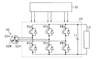
- FIG. 2 is a diagram showing an inverter and its peripheral configuration.
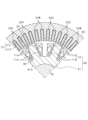
- FIG. 3 is a cross-sectional view of the rotor and the stator;
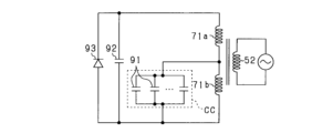
- FIG. 4 is a diagram showing an electric circuit provided in the rotor;
- FIG. 5 is a perspective view showing the overall configuration of the rotor;
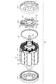
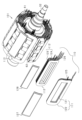
- FIG. 6 is an exploded perspective view of the rotor;
- FIG. 7 is a longitudinal sectional view of the rotor;
- FIG. 8 is an exploded perspective view of a winding unit in a rotor main portion;
- FIG. 1 is a diagram showing the overall configuration of a control system for a rotating electrical machine
- FIG. 2 is a diagram showing an inverter and its peripheral configuration.
- FIG. 3 is a cross-sectional view of the rotor and the stator
- FIG. 4 is a diagram showing an electric circuit provided in the rotor
- FIG. 5
- FIG. 9 is a cross-sectional view of a rotor main portion;
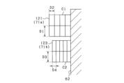
- FIG. 10 is a cross-sectional view showing a schematic diagram of each conductive wire of a first winding portion and a second winding portion;
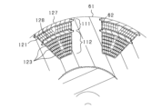
- FIG. 11 is a schematic diagram showing a state in which windings are wound around each main pole of a rotor core;
- FIG. 12 is a perspective view showing a configuration related to connections of coil bodies in each winding portion;
- FIG. 13 is an electrical circuit diagram of the rotor;
- FIG. 14 is a cross-sectional view of a conductive wire;
- FIG. 15 is a vertical cross-sectional view showing a state in which the conductor ends of the coil body are joined together in the part holder;
- FIG. 16 is a cross-sectional view showing a schematic diagram of each of the conductors of the first winding portion and the second winding portion.
- the rotating electric machine is used as a driving power source in, for example, electric vehicles, hybrid vehicles, and other electrically powered vehicles.
- the control system includes a DC power supply 10, an inverter 20, a control device 30, and a rotating electric machine 40.
- the rotating electric machine 40 is a wound-field type synchronous machine.
- the rotating electric machine 40, the inverter 20, and the control device 30 may be configured as an electromechanical integrated drive device, or the rotating electric machine 40, the inverter 20, and the control device 30 may each be configured with its own component.
- the rotating electric machine 40 includes a housing 41, and a stator 50 and a rotor 60 housed within the housing 41.
- the rotating electric machine 40 of this embodiment is an inner rotor type rotating electric machine in which the rotor 60 is disposed radially inside the stator 50.
- the stator 50 includes a stator core 51 and a stator winding 52.
- the stator winding 52 is made of, for example, copper wire, and includes U-, V-, and W-phase windings 52U, 52V, and 52W that are disposed with an electrical angle of 120° from each other.
- the rotor 60 includes a rotor core 61 and a field winding 70.
- a rotating shaft 32 is attached to the central hole of the rotor core 61.
- the rotating shaft 32 is rotatably supported by the housing 41 via bearings 42 and 43.
- the inverter 20 includes a series connection of upper arm switches SUp, SVp, SWp for the U-, V-, and W-phases, and lower arm switches SUn, SVn, SWn for the U-, V-, and W-phases.
- First ends of the U-, V-, and W-phase windings 52U, 52V, and 52W are connected to the connection points of the upper arm switches SUp, SVp, and SWp and the lower arm switches SUn, SVn, and SWn in each phase.
- Second ends of the U-, V-, and W-phase windings 52U, 52V, and 52W are connected at the neutral point. That is, in this embodiment, the stator winding 52 is star-connected. However, the stator winding 52 may also be delta-connected.
- each switch SUp to SWn is an IGBT.
- a freewheel diode is connected in inverse parallel to each switch SUp to SWn.
- the positive terminal of the DC power supply 10 is connected to the collector of the upper arm switches SUp, SVp, SWp of each phase.
- the negative terminal of the DC power supply 10 is connected to the emitter of the lower arm switches SUn, SVn, SWn of each phase.
- a smoothing capacitor 11 is connected in parallel to the DC power supply 10.
- stator 50 and rotor 60 will be described using FIG. 3.
- the stator 50 and the rotor 60 are both arranged coaxially with the rotating shaft 32.
- the direction in which the rotating shaft 32 extends is referred to as the axial direction
- the direction extending radially from the center of the rotating shaft 32 is referred to as the radial direction
- the direction extending circumferentially around the rotating shaft 32 is referred to as the circumferential direction.
- the stator core 51 is made of laminated steel plates made of soft magnetic material, and has an annular back yoke 51a and a number of teeth 51b protruding radially inward from the back yoke 51a.
- a number of slots 54 are formed between adjacent teeth 51b, arranged in the circumferential direction.
- the stator winding 52 is formed by accommodating the phase windings of each phase in a predetermined order in each of these slots 54.
- the stator 50 may employ a segment coil structure using a number of conductor segments.
- the structure of the stator winding 52 is arbitrary.
- the rotor core 61 is made of a soft magnetic material, for example laminated steel plates.
- the rotor core 61 has a cylindrical portion 61a and a number of main pole portions 62 that protrude radially outward from the cylindrical portion 61a.
- a field winding 70 is wound around the main pole portions 62 by concentrated winding.
- eight main pole portions 62 are provided at equal intervals in the circumferential direction.
- the field winding 70 has a first winding portion 71a and a second winding portion 71b.
- the first winding portion 71a is wound radially outward around each main pole portion 62, and the second winding portion 71b is wound radially inward from the first winding portion 71a.
- the first winding portion 71a is wound radially closer to the stator 50, and the second winding portion 71b is wound radially farther from the stator 50.
- the winding directions of the first winding portion 71a and the second winding portion 71b are the same.
- each main pole portion 62 in the rotor core 61 and the field winding 70 wound around each main pole portion 62 form multiple magnetic poles (field poles) arranged in the circumferential direction.
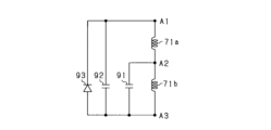
- FIG. 4 shows the electric circuit on the rotor 60 side, which includes the winding portions 71a, 71b wound around the main pole portion 62.
- the first winding portion 71a and the second winding portion 71b are connected in series, and a capacitor portion CC consisting of a plurality of first capacitors 91 is connected in parallel to the second winding portion 71b.
- the capacitor portion CC is configured as a parallel connection of a plurality of first capacitors 91.
- a second capacitor 92 is connected in parallel to the series connection of the first winding portion 71a and the second winding portion 71b.
- the second capacitor 92 is provided for noise suppression.
- the first capacitor 91 and the second capacitor 92 are, for example, multilayer ceramic capacitors, and have the same configuration.
- a diode 93 is connected as a rectifying element between both ends of the series-connected body consisting of the winding portions 71a and 71b. That is, the first end of the first winding portion 71a is connected to the cathode of the diode 93, and the first end of the second winding portion 71b is connected to the second end of the first winding portion 71a.
- the anode of the diode 93 is connected to the second end of the second winding portion 71b.
- the first winding portion 71a, the first capacitor 91, and the diode 93 form a series resonant circuit
- the second winding portion 71b and the first capacitor 91 form a parallel resonant circuit
- the first winding portion 71a is connected in series to the first capacitor 91
- the second winding portion 71b is connected in parallel to the first capacitor 91. If the first resonant frequency, which is the resonant frequency of the series resonant circuit, is f1 and the second resonant frequency, which is the resonant frequency of the parallel resonant circuit, is f2, these resonant frequencies f1 and f2 are expressed by the following formulas (1) and (2).
- L1 is the inductance of the first winding portion 71a
- L2 is the inductance of the second winding portion 71b
- C is the capacitance of the first capacitor 91.
- f1 1/(2 ⁇ (L1 ⁇ C))...(1)
- f2 1/(2 ⁇ (L2 ⁇ C))...(2)
- a high-frequency excitation current flows through the stator winding 52
- a fluctuation occurs in the magnetic circuit including the stator core 51 and the rotor core 61 due to the high-frequency component of the main magnetic flux.
- the fluctuation in the main magnetic flux generates an induced voltage in each of the winding parts 71a, 71b, and a current is induced in each of the winding parts 71a, 71b.
- the control device 30 is mainly composed of a microcomputer (corresponding to a computer), which has a CPU.
- the control device 30 generates drive signals that turn on and off each of the switches SUp to SWn that make up the inverter 20.
- the control device 30 generates drive signals that turn on and off each of the switches SUp to SWn in order to convert the DC power output from the DC power source 10 into AC power and supply it to the U-, V-, and W-phase windings 52U, 52V, and 52W, and supplies the generated drive signals to the gates of each of the switches SUp to SWn.
- the control device 30 turns on and off each switch SUp to SWn so that a composite current of the fundamental current and high-frequency excitation current flows through each phase winding 52U, 52V, 52W.
- the fundamental current is a current that mainly generates torque in the rotating electric machine 40.
- the high-frequency excitation current is a high-frequency current with a higher frequency than the fundamental current, and is a current that mainly excites the field winding 70. It is also possible to use a harmonic current as the high-frequency current.
- the phase currents flowing through each phase winding 52U, 52V, 52W are shifted by 120° in electrical angle.
- Figure 5 is a perspective view showing the overall configuration of the rotor 60
- Figure 6 is an exploded perspective view of the rotor 60
- Figure 7 is a longitudinal cross-sectional view of the rotor 60.
- the rotor 60 is broadly divided into a rotor main part 101, a circuit module 102 provided at one of the axial ends of the rotor main part 101, and coil end covers 103, 104 as circular members attached to one and the other axial ends of the rotor main part 101.
- the rotor main part 101 includes a rotor core 61 and a field winding 70, and the rotating shaft 32 is attached to the central hole of the rotor core 61.
- the field winding 70 is made up of a plurality of winding units 110 arranged in a circumferential direction.
- the circuit module 102 is fixed to the rotating shaft 32 with the rotating shaft 32 inserted into the hollow portion.
- the circuit module 102 is provided at a position axially facing the coil end portion of the field winding 70.
- the circuit module 102 is an electric circuit section including the capacitors 91, 92 and diode 93 described in FIG. 4, as well as bus bars that electrically connect these elements.
- FIG. 8 is an exploded perspective view of the winding unit 110 in the rotor main part 101
- FIG. 9 is a cross-sectional view showing the cross-sectional structure of a portion of the rotor main part 101.
- the rotor main part 101 has multiple winding units 110 provided for each magnetic pole of the rotor 60.
- Each winding unit 110 is formed in an annular shape with the axial direction as the longitudinal direction, and is assembled to the rotor core 61 with the main pole part 62 of the rotor core 61 inserted into the hollow part.
- the winding unit 110 has a first coil module 111 that is radially outward when attached to the main pole portion 62, and a second coil module 112 that is radially inward.
- the first coil module 111 is a coil module that corresponds to the first winding portion 71a
- the second coil module 112 is a coil module that corresponds to the second winding portion 71b.
- the first coil module 111 has an annular coil body 121 formed by multiple windings of conductor material made of rectangular wire in the circumferential and radial directions of the rotor 60, and a thin plate-like insulator 122 that is integral with the coil body 121.
- the insulator 122 has a portion that extends in the circumferential direction and covers the radially outer and inner sides of the coil body 121, and a portion that extends in the radial direction and covers the hollow part of the coil body 121.
- the coil body 121 is insulated by the insulator 122 at the radially inner and outer parts and at the inner peripheral part facing the main pole 62.
- the second coil module 112 has an annular coil body 123 formed by multiple windings of conductor material made of rectangular wire in the circumferential and radial directions of the rotor 60, and a thin plate-like insulator 124 that is integral with the coil body 123.
- the insulator 124 has a portion that extends in the circumferential direction and covers the radially outer and inner sides of the coil body 123, and a portion that extends in the radial direction and covers the hollow part of the coil body 123.
- the coil body 123 is insulated by the insulator 124 at the radially inner and outer parts and at the inner peripheral part facing the main pole 62.
- the coil bodies 121, 123 are configured as, for example, ⁇ -wound coils, and are air-core coils in which the conductor material is wound so that it is multiple in the overlapping direction of the turns (rotor circumferential direction) and in two layers in the direction in which the hollow portion extends (rotor radial direction).
- the conductor material of the coil bodies 121, 123 is a rectangular flat conductor wire whose conductor cross section has long and short sides.
- the coil bodies 121, 123 are wound in a direction in which the long sides overlap in multiple layers due to the turns of the conductor material.
- the flat wire consists of a conductor made of aluminum or the like and an insulating layer that covers the conductor.
- first coil module 111 two conductor ends 125 are pulled out in the axial direction from one coil body 121.
- second coil module 112 a total of six conductor ends 126 are pulled out in the axial direction from three coil bodies 123 arranged radially.
- the conductor wire is wound in two radial layers, and in the second coil module 112, the conductor wire is wound in six radial layers.
- the coil bodies 121 and 123 in the first coil module 111, one coil body 121 is provided in the radial direction, and in the second coil module 112, three coil bodies 123 are provided in a row in the radial direction. In this case, the number of turns of the second winding portion 71b in each main pole portion 62 is greater than the number of turns of the first winding portion 71a.
- the number of turns in the circumferential direction differs in each coil module 111 and 112, and the number of turns is greater on the radial outer side than on the radial inner side. This improves the space factor of the field winding 70.
- retaining plates 127, 128 that retain the assembled state of the first coil module 111 and the second coil module 112 when these coil modules 111, 112 are assembled to each main pole section 62.
- the retaining plate 127 is attached to the radial outside of the first coil module 111, and the retaining plate 128 is attached between the first coil module 111 and the second coil module 112.
- the windings 71a, 71b of the field winding 70 and the first capacitor 91 form a series resonant circuit and a parallel resonant circuit, and the number of turns of the radially inner second winding 71b is greater than the number of turns of the radially outer first winding 71a.
- the inductance of the second winding 71b increases, making it possible to increase the field current.
- the conductor cross-sectional area of the conductor wire used in the second winding portion 71b is made smaller than the conductor cross-sectional area of the conductor wire used in the first winding portion 71a.
- the following describes the characteristics of the winding structure of the field winding 70.
- the length dimension of the long side of the conductor C2 is the same as that of the conductor C1, and the length dimension of the short side is smaller.
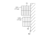
- FIG. 11 is a schematic diagram showing the state in which the winding sections 71a, 71b are wound around the main pole sections 62 of the rotor core 61.
- the two radially outer conductor layers are the first winding section 71a
- the four radially inner conductor layers are the second winding section 71b.
- the first winding section 71a is constructed by assembling coil bodies 121 to the main pole sections 62 lined up in the circumferential direction, and connecting the coil bodies 121 in series.
- the coil bodies 121 constituting the first winding section 71a are numbered C11, C12, C13, ... C18 in clockwise order
- the first winding section 71a is constructed by connecting the coil bodies C11 to C18 in series with the coil bodies adjacent to each other in the circumferential direction.
- the second winding section 71b is configured by assembling two coil bodies 123 to each of the main pole parts 62 arranged in the circumferential direction, and connecting the coil bodies 123 in series.
- the coil bodies 123 of the second winding section 71b adjacent to the first winding section 71a are designated C21, C22, C23, ... C28, and the coil bodies 123 radially inside are designated C31, C32, C33, ... C38.
- the second winding section 71b is configured by connecting one end of the series-connected coil bodies C21 to C28 to one end of the series-connected coil bodies C31 to C38.
- two coil bodies 123 are assembled to each main pole part 62, but the same applies when three or more coil bodies are assembled.
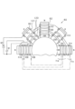
- Figure 12 is a perspective view showing the configuration of the connection of the coil bodies 121, 123 in each winding section 71a, 71b in the rotor 60.
- Figure 12 shows the state in which the circuit module 102 is assembled to one axial side of the rotor main section 101.
- the circuit module 102 includes a component holder 130 that holds the capacitors 91, 92 and diode 93 described above.
- the component holder 130 is made of an electrically insulating material such as synthetic resin.
- the component holder 130 includes a main body 131 that forms an annular ring, and a plurality of conductor fixing portions 132 that extend radially outward from the main body 131.
- the main body 131 has the capacitors 91, 92 and diodes 93 arranged in a ring shape surrounding the rotating shaft 32.
- the component holder 130 is provided with eight conductor fixing portions 132, the same number as the main pole portions 62.
- Each conductor fixing portion 132 has a plurality of insertion holes 133 formed therethrough that penetrate in the axial direction.
- the conductor ends 125, 126 extending from the coil bodies 121, 123 of each winding portion 71a, 71b are inserted into each of these insertion holes 133, and the conductor ends 125, 126 inserted into the conductor ends 125, 126 are joined together by welding or the like.
- connection points X1 to X4 i.e., the locations where the conductor ends 125 or 126 of the coil bodies 121, 123 are connected to each other, the coil bodies 121, 123 are connected by welding or the like with the long sides of the conductor material, which is a rectangular wire, joined to each other.
- a larger joint surface can be ensured compared to a configuration in which the short sides of the conductor material are joined to each other. This allows for an appropriate connection in terms of both strength and conductivity.
- the conductor ends 126 of the coil bodies 123 are connected to each other at three connection points X2 to X4.
- the conductor ends 126 are connected to each other at the same number of points as the number of coil bodies 123 arranged in the circumferential direction.
- the conductor cross-sectional area of the conductor material C2 of the coil body 123 is made smaller than the conductor material C1 of the coil body 121, and the radial width dimension of the conductor material C2 in the second winding portion 71b is made smaller than the conductor material C1, the number of coil bodies 123 arranged in the radial direction increases, and the number of connection points connecting the coil bodies 123 to each other increases.
- the circumferential width dimension of the conductor material C2 is made smaller than the conductor material C1 as a configuration for reducing the cross-sectional area of the conductor material C2, so the number of coil bodies 123 arranged in the radial direction does not increase. This suppresses a decrease in workability due to an increase in the number of connection points between the coil bodies 123.
- the coil bodies 121, 123 in each row are connected to each other in different rows (lane change connection), and are connected to each capacitor 91, 92 and diode 93 via a bus bar.
- the conductor end 125 of the coil body 121 of the first winding portion 71a, one end of the bus bar 143 for the second capacitor 92, and an end of the bus bar 144 for connecting the cathode of the diode 93 are connected.
- This connection at the connection portion Y1 corresponds to the connection at the connection point A1 in the circuit diagram of FIG. 13.
- connection portion Y2 the conductor end 125 of the coil body 121 of the first winding portion 71a, the conductor end 126 of the coil body 123 of the second winding portion 71b, and an end of the bus bar 142 for the first capacitor 91 are connected.
- This connection at connection point Y2 corresponds to the connection at connection point A2 in the circuit diagram in FIG. 13.
- connection points Y3 and Y4 the conductor ends 126 of the coil bodies 123 in different rows are connected to each other.
- connection point Y5 bus bars 143 and 145 are connected for connection to the second capacitor 92.
- At least one of the conductor wires C1, C2 of the first winding section 71a and the second winding section 71b may be a bundled wire (split wire) made of multiple strands bundled together.
- the conductors C1 and C2 may be composed of different strands 151, and for example, the cross section of the strands 151 of the conductor C1 may be larger than the cross section of the strands 151 of the conductor C2.
- the strands 151 are rectangular in cross section, but may be round.
- the conductor wires C1 and C2 may be twisted wires in which multiple wires 151 are twisted together.
- each winding section 71a, 71b may be affected by the skin effect.
- the conductor wires C1, C2 of each winding section 71a, 71b into a bundled wire of multiple strands 151, i.e., a divided wire in which the conductor cross section is divided into multiple parts, the influence of the skin effect in each winding section 71a, 71b is reduced.
- the first winding portion 71a on the radially outer side is closer to the stator 50, and the second winding portion 71b on the radially inner side is farther from the stator 50, and there is concern that eddy current loss will occur in the first winding portion 71a due to linkage of leakage flux of high frequency excitation magnetic flux from the stator 50.
- the conductor material of the first winding portion 71a (coil body 121) is aluminum, and the conductor material of the second winding portion 71b (coil body 123) is copper. It is also possible to use CNT (carbon nanotube) as the conductor material of the first winding portion 71a and copper as the conductor material of the second winding portion 71b. This reduces the effect of leakage flux in the first winding portion 71a, making it possible to reduce eddy current loss.
- CNT carbon nanotube
- the wire materials of the winding portions 71a and 71b are different from each other, and the second winding portion 71b, which is relatively less affected by leakage flux, is made of a material with low electrical resistance, which suppresses current reduction in the second winding portion 71b.
- the conductor material of the first winding portion 71a has a higher volume resistivity and a lower specific gravity than the conductor material of the second winding portion 71b. This makes it possible to reduce eddy current loss caused by leakage flux from the stator 50 in the first winding portion 71a on the radial outside (stator 50 side), as well as to reduce centrifugal force during rotor rotation.
- first winding portion 71a and the second winding portion 71b are made of different materials, there is a concern that galvanic corrosion may occur due to moisture adhering to the joints. In consideration of this, it is advisable that the joints between the conductor materials in the first winding portion 71a and the second winding portion 71b are covered with an insulating material.
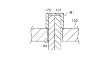
- FIG. 15 is a longitudinal cross-sectional view showing the state in which the conductor end 125 of the coil body 121 and the conductor end 126 of the coil body 123 are joined in the component holder 130 of the circuit module 102.
- the conductor ends 125, 126 of the coil bodies 121, 123 are inserted into the insertion holes 133 in the conductor fixing portion 132 of the component holder 130 and joined at their tip sides by welding or the like.
- a resin coating portion 161 made of a resin material such as epoxy resin is formed so as to cover the joint portion of the conductor ends 125, 126.
- the resin coating portion 161 is provided so as to cover the entire joint portion of the conductor ends 125, 126 and so as to have a portion thereof enter the insertion hole 133 of the conductor fixing portion 132.
- the resin coating 161 prevents galvanic corrosion at the joint between the first winding portion 71a and the second winding portion 71b, even if they are made of different materials.
- the resin coating portion 161 is provided not only at the joint between the conductor end portion 125 of the coil body 121 and the conductor end portion 126 of the coil body 123, but also at other joint portions, i.e., the joint between the conductor end portions 125 of the coil body 121 and the joint between the conductor end portions 126 of the coil body 123.
- the volume resistivity of the conductor material of the first winding portion 71a is made greater than the volume resistivity of the conductor material of the second winding portion 71b. This reduces the effect of leakage flux in the first winding portion 71a. As a result, it is possible to reduce eddy current loss in the first winding portion 71a, which is on the stator 50 side of the winding portions 71a and 71b that make up the field winding 70.
- the conductor material of the first winding portion 71a has a higher volume resistivity and a lower specific gravity than the conductor material of the second winding portion 71b.
- a high-resistance, lightweight material that is relatively highly resistive and lightweight is used as the conductor material of the first winding portion 71a on the radially outer side. This makes it possible to reduce eddy current loss in the first winding portion 71a as well as the centrifugal force during rotor rotation.
- each winding section 71a, 71b may be affected by the skin effect.
- the skin effect in each winding section 71a, 71b can be reduced, and further loss reduction can be achieved.
- first winding portion 71a and the second winding portion 71b of the field winding 70 are made of different materials, there is a concern that galvanic corrosion may occur due to moisture adhering to the joints.
- the joints between the conductor materials in the first winding portion 71a and the second winding portion 71b are covered with an insulating material. This makes it possible to suppress galvanic corrosion at the joints even if the first winding portion 71a and the second winding portion 71b are made of different materials.
- each winding portion 71a, 71b may be a bundled wire, or neither of the conductor wires C1, C2 may be a bundled wire.
- FIG. 16 shows a configuration in which the conductor wire C1 of the first winding portion 71a is a bundled wire, and the conductor wire C2 of the second winding portion 71b is a solid wire rather than a bundled wire.
- the effect of reducing overcurrent loss can be improved in the first winding portion 71a, which is susceptible to leakage flux of high-frequency excitation magnetic flux from the stator 50.
- bundled wire is more likely to have variations in outer diameter dimensions than solid wire, and if the second winding portion 71b, which is wound around the radially inner portion of the main pole portion 62, is a bundled wire, there is a concern that the winding of the conductor wire will be hindered due to dimensional variations in the relatively narrow space.
- the second winding portion 71b by making the second winding portion 71b a solid wire rather than a bundled wire, it is possible to suppress the occurrence of problems in the winding of the conductor wire.
- the conductor cross-sectional area of the conductor wire C2 of the second winding portion 71b is smaller than the conductor cross-sectional area of the conductor wire C1 of the first winding portion 71a by making the length dimension of the long side of the conductor wire C2 the same as that of the conductor wire C1 and making the length dimension of the short side smaller (see FIG. 10), but this may be changed.
- the conductor wire C2 may be configured to have the same length dimension of the short side as that of the conductor wire C1 and to have a smaller length dimension of the long side.
- the conductor wire C2 may be configured to have smaller length dimensions of the long side and the short side than that of the conductor wire C1.
- the conductor wire of each of the winding sections 71a, 71b is a rectangular wire, but this may be changed.
- the conductor wire of one of the winding sections 71a, 71b may be a rectangular wire and the conductor wire of the other may be a round wire.
- both conductor wires may be round wire.
- the ends of the conductors of the coil bodies 121, 123 in each winding section 71a, 71b are joined by welding, but this may be modified so that the ends of the conductors are joined by crimping, bolting, or the like.
- each winding section 71a, 71b can be the same.
- the conductor material of each winding section 71a, 71b can be, for example, aluminum, copper, or CNT.
- the rotating electric machine is not limited to an inner rotor type rotating electric machine, and may be an outer rotor type rotating electric machine.
- the stator 50 is arranged radially inward and the rotor 60 is arranged radially outward.
- the main pole portion 62 protrudes radially inward from the annular yoke portion of the rotor core.
- the first winding portion 71a is preferably arranged radially inward (on the stator 50 side) and the second winding portion 71b is preferably arranged radially outward (opposite the stator side).
- the stator core may be a teeth-less core that does not have teeth.
- the rotating electric machine is not limited to a rotating electric machine used as an in-vehicle main engine, but may be, for example, a rotating electric machine used as an ISG (Integrated Starter Generator), which is both a motor and a generator.
- ISG Integrated Starter Generator
- the moving body on which the rotating electric motor system is mounted is not limited to a vehicle, but may be, for example, an aircraft or a ship. Furthermore, the rotating electric motor system is not limited to a system mounted on a moving body, but may be a stationary system.
- the field winding has a series connection of a first winding portion (71 a) and a second winding portion (71 b), and each winding portion is wound around each of the main pole portions with the first winding portion on the side closer to the stator and the second winding portion on the side farther from the stator in the radial direction, the first winding portion is connected in series to a capacitor (91) to form a series resonant circuit, and the second winding portion is
- the wound-field type rotating electric machine according to configuration 1 or 2 wherein the conductor material of at least one of the first winding portion and the second winding portion is a bundled wire formed by bundling a plurality of strands.
- the wound field type rotating electric machine according to configuration 1 or 2 wherein the conductor material of the first winding portion is a bundled wire formed by bundling a plurality of wires, and the conductor material of the second winding portion is not the bundled wire.
- the first winding portion and the second winding portion are electrically connected to each other by joining the respective conductive wires to each other, 5.
- the wound field type rotating electric machine according to any one of configurations 1 to 4, wherein a joint between the conductors in the first winding portion and the second winding portion is covered with an insulating material.
Landscapes
- Engineering & Computer Science (AREA)
- Power Engineering (AREA)
- Windings For Motors And Generators (AREA)
- Synchronous Machinery (AREA)
Applications Claiming Priority (2)
| Application Number | Priority Date | Filing Date | Title |
|---|---|---|---|
| JP2023118125A JP2025015046A (ja) | 2023-07-20 | 2023-07-20 | 巻線界磁型回転電機 |
| JP2023-118125 | 2023-07-20 |
Publications (1)
| Publication Number | Publication Date |
|---|---|
| WO2025018153A1 true WO2025018153A1 (ja) | 2025-01-23 |
Family
ID=94281537
Family Applications (1)
| Application Number | Title | Priority Date | Filing Date |
|---|---|---|---|
| PCT/JP2024/024093 Pending WO2025018153A1 (ja) | 2023-07-20 | 2024-07-03 | 巻線界磁型回転電機 |
Country Status (2)
| Country | Link |
|---|---|
| JP (1) | JP2025015046A (enExample) |
| WO (1) | WO2025018153A1 (enExample) |
Citations (3)
| Publication number | Priority date | Publication date | Assignee | Title |
|---|---|---|---|---|
| JP2006019155A (ja) * | 2004-07-02 | 2006-01-19 | Toyota Motor Corp | 組電池,電池および接続継ぎ手 |
| JP2013038918A (ja) * | 2011-08-08 | 2013-02-21 | Toyota Motor Corp | 回転電機 |
| JP2020191743A (ja) * | 2019-05-22 | 2020-11-26 | 株式会社デンソー | 界磁巻線型回転電機 |
-
2023
- 2023-07-20 JP JP2023118125A patent/JP2025015046A/ja active Pending
-
2024
- 2024-07-03 WO PCT/JP2024/024093 patent/WO2025018153A1/ja active Pending
Patent Citations (3)
| Publication number | Priority date | Publication date | Assignee | Title |
|---|---|---|---|---|
| JP2006019155A (ja) * | 2004-07-02 | 2006-01-19 | Toyota Motor Corp | 組電池,電池および接続継ぎ手 |
| JP2013038918A (ja) * | 2011-08-08 | 2013-02-21 | Toyota Motor Corp | 回転電機 |
| JP2020191743A (ja) * | 2019-05-22 | 2020-11-26 | 株式会社デンソー | 界磁巻線型回転電機 |
Also Published As
| Publication number | Publication date |
|---|---|
| JP2025015046A (ja) | 2025-01-30 |
Similar Documents
| Publication | Publication Date | Title |
|---|---|---|
| JP7283091B2 (ja) | 界磁巻線型回転電機 | |
| US12212200B2 (en) | Motor | |
| JP2006187164A (ja) | 回転電機 | |
| WO2025018153A1 (ja) | 巻線界磁型回転電機 | |
| WO2025018154A1 (ja) | 巻線界磁型回転電機 | |
| WO2025154564A1 (ja) | 巻線界磁型回転電機 | |
| EP4604366A1 (en) | Winding field rotor | |
| WO2025009561A1 (ja) | 巻線界磁型回転電機 | |
| JP2025107881A (ja) | 巻線界磁ロータ | |
| WO2025220399A1 (ja) | 巻線界磁型回転電機 | |
| WO2025009560A1 (ja) | 巻線界磁型回転電機 | |
| US20250385580A1 (en) | Wound-field rotating electric machine | |
| WO2025220400A1 (ja) | 巻線界磁ロータ | |
| US20250385581A1 (en) | Wound-field rotor | |
| WO2025154563A1 (ja) | 巻線界磁型回転電機 | |
| WO2025216020A1 (ja) | 巻線界磁ロータ | |
| WO2025216021A1 (ja) | 巻線界磁ロータ | |
| WO2025211085A1 (ja) | 巻線界磁ロータ | |
| WO2025169714A1 (ja) | 巻線界磁ロータ | |
| WO2024262236A1 (ja) | 回転電機 | |
| WO2025169713A1 (ja) | 巻線界磁ロータ | |
| WO2025022922A1 (ja) | 巻線界磁ロータ、回転電機 | |
| WO2025033124A1 (ja) | 巻線界磁型回転電機 | |
| JP2022178242A (ja) | ステータ及びモータ |
Legal Events
| Date | Code | Title | Description |
|---|---|---|---|
| 121 | Ep: the epo has been informed by wipo that ep was designated in this application |
Ref document number: 24842946 Country of ref document: EP Kind code of ref document: A1 |