WO2025018151A1 - 電池セル - Google Patents
電池セル Download PDFInfo
- Publication number
- WO2025018151A1 WO2025018151A1 PCT/JP2024/024088 JP2024024088W WO2025018151A1 WO 2025018151 A1 WO2025018151 A1 WO 2025018151A1 JP 2024024088 W JP2024024088 W JP 2024024088W WO 2025018151 A1 WO2025018151 A1 WO 2025018151A1
- Authority
- WO
- WIPO (PCT)
- Prior art keywords
- conductor
- battery element
- battery
- front cover
- battery cell
- Prior art date
- Legal status (The legal status is an assumption and is not a legal conclusion. Google has not performed a legal analysis and makes no representation as to the accuracy of the status listed.)
- Pending
Links
Images






Classifications
-
- Y—GENERAL TAGGING OF NEW TECHNOLOGICAL DEVELOPMENTS; GENERAL TAGGING OF CROSS-SECTIONAL TECHNOLOGIES SPANNING OVER SEVERAL SECTIONS OF THE IPC; TECHNICAL SUBJECTS COVERED BY FORMER USPC CROSS-REFERENCE ART COLLECTIONS [XRACs] AND DIGESTS
- Y02—TECHNOLOGIES OR APPLICATIONS FOR MITIGATION OR ADAPTATION AGAINST CLIMATE CHANGE
- Y02E—REDUCTION OF GREENHOUSE GAS [GHG] EMISSIONS, RELATED TO ENERGY GENERATION, TRANSMISSION OR DISTRIBUTION
- Y02E60/00—Enabling technologies; Technologies with a potential or indirect contribution to GHG emissions mitigation
- Y02E60/10—Energy storage using batteries
Definitions
- the present invention relates to a battery cell.
- a battery cell has battery elements that include a positive electrode, a negative electrode, and a separator.
- Patent Document 1 describes an example of a battery cell.
- This battery cell is provided with an exterior material that seals the battery element.
- the battery element is provided with a positive electrode lead and a negative electrode lead.
- a temperature sensor is disposed on the negative electrode lead.
- Patent document 2 describes placing a temperature sensor on the side of the cell.
- Patent document 3 describes inserting a temperature sensor into a hole provided in the battery case and top lid that house the electrode plate group.
- a battery cell may have a structure that at least partially faces an end face of a battery element at a predetermined distance. However, if the structure simply faces the end face of the battery element, it may be difficult to improve the functionality of the structure.
- One object of the present invention is to improve the functionality of a structure that at least partially faces an end face of a battery element. Other objects of the present invention will become apparent from the description of this specification.
- a battery element a structure at least partially facing an end surface of the battery element at a predetermined distance; Equipped with the structure has a protrusion located on a side where the end surface of the battery element is located, The structure defines a recessed space recessed toward the protrusion from a side of the structure opposite to a side on which the end face of the battery element is located.
- the battery cell according to 1. further comprising a temperature sensor at least a portion of which is disposed inside the recessed space.
- the structural body defines a plurality of the recessed spaces. 5.
- the above aspect of the present invention can improve the functionality of the structure that at least partially faces the end face of the battery element.
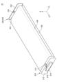
- FIG. 2 is a perspective view of a battery cell according to an embodiment.
- FIG. 2 is a perspective view of a battery cell according to an embodiment with an exterior film removed.
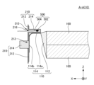
- 2 is a cross-sectional view taken along line AA of FIG. 1.
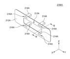
- FIG. 11 is a perspective view of a front cover member according to a first modified example of the embodiment.
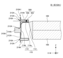
- 5 is a cross-sectional view of a battery cell according to a first modified example of the embodiment, taken at a position corresponding to the cross section BB in FIG. 4.
- FIG. 11 is a perspective view of a front cover member according to a second modified example of the embodiment.
- 7 is a cross-sectional view of a battery cell according to a second modified example of the embodiment, taken at a position corresponding to cross section CC in FIG. 6.
- FIG. 13 is a perspective view of a front cover member according to a third modified example of the embodiment.
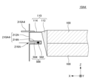
- FIG. 13 is a cross-sectional view of a battery cell according to a fourth modified example of the embodiment.
- FIG. 13 is a cross-sectional view of a front conductor according to a fifth modified example of the embodiment.
- FIG. 11 is a cross-sectional view of a battery cell according to a modified example.
- FIG. 1 is a perspective view of a battery cell 10 according to an embodiment.
- FIG. 2 is a perspective view of a battery cell 10 according to an embodiment with an exterior film 400 removed.
- FIG. 3 is a cross-sectional view taken along line A-A in FIG. 1.
- the temperature sensor 500 shown in FIG. 3 has been removed from FIG. 1 and FIG. 2.
- the exterior film 400 shown in FIG. 1 has been removed from FIG. 3.
- each figure is labeled with an X direction, a Y direction, and a Z direction.
- the X direction indicates the front-rear direction of the battery cell 10.
- the Y direction is perpendicular to the X direction.
- the Y direction indicates the left-right direction of the battery cell 10.
- the Z direction is perpendicular to both the X direction and the Y direction.
- the Z direction indicates the up-down direction of the battery cell 10.
- the directions indicated by the arrow indicating the X direction, the arrow indicating the Y direction, and the arrow indicating the Z direction are the forward direction, the left direction, and the upward direction, respectively.
- the relationship between the X direction, the Y direction, the Z direction, the front-rear direction, the left-right direction, and the up-down direction of the battery cell 10 is not limited to this example.
- the white circle with a black dot indicating the Y direction indicates that the direction from the back of the paper to the front is the direction indicated by the arrow indicating that direction.
- the battery cell 10 includes two battery elements 100, a front cover material 210, a rear cover material 220, a front conductor 310, a rear conductor 320, an exterior film 400, and a temperature sensor 500.
- each battery element 100 has a substantially rectangular parallelepiped shape.
- the dimension of each battery element 100 in the X direction is the dimension in the longitudinal direction of each battery element 100.
- the dimension of each battery element 100 in the Y direction is the dimension in the lateral direction of each battery element 100.
- the dimension of each battery element 100 in the Z direction is the dimension in the thickness direction of each battery element 100.
- the shape of the battery element 100 is not limited to this example.
- the number of battery elements 100 included in the battery cell 10 may be only one or three or more.
- Each battery element 100 has at least one positive electrode (not shown), at least one negative electrode (not shown), and at least one separator (not shown).
- multiple positive electrodes and multiple negative electrodes are alternately stacked in the Z direction. At least a portion of the separator is located between the positive electrodes and negative electrodes adjacent in the Z direction.
- multiple sheet-like separators are each located between the positive electrodes and negative electrodes adjacent in the Z direction.
- one sheet-like separator may be alternately folded over at the left end of the positive electrode and the right end of the negative electrode, or alternately folded over at the right end of the positive electrode and the left end of the negative electrode.
- the positive electrode, the negative electrode, and the separator may be wound so that the separator is disposed between the positive electrode and the negative electrode.
- the positive electrode, the negative electrode, and the separator are wound with both sides of one of the positive electrode and the negative electrode covered by the separator.
- a laminate including multiple unit laminates including a positive electrode, a separator, and a negative electrode in this order may be wound.
- the winding structure of the positive electrode, the negative electrode, and the separator is not limited to these examples.
- the battery cell 10 is a battery cell that contains an electrolyte.
- the battery cell 10 may be an all-solid-state battery.
- an all-solid-state battery a solid electrolyte layer is provided in the portion that corresponds to the separator.
- An all-solid-state battery does not contain an electrolyte.
- each battery element 100 will be described as including multiple positive electrodes and multiple negative electrodes stacked alternately in the Z direction.
- a plurality of positive electrode collectors 110 are pulled out from the front end surface of each battery element 100.
- the plurality of positive electrode collectors 110 are integrated with the plurality of positive electrodes of each battery element 100 and are electrically connected to the plurality of positive electrodes of each battery element 100.
- the plurality of positive electrode collectors 110 are bundled together.
- the plurality of bundled positive electrode collectors 110 are depicted as a single solid.
- the bundle of the plurality of positive electrode collectors 110 has a tapered bundle portion 112 and a pulled-out bundle portion 114. In the tapered bundle portion 112, the Z-direction distance between the adjacent positive electrode collectors 110 in the Z direction decreases toward the front.
- the front end of the tapered bundle portion 112 is positioned above the center of the two positive electrode collectors 110 in the Z direction.
- the positive electrode current collectors 110 in the drawn bundle portion 114 are joined to each other by a joining method such as ultrasonic joining.
- the positive electrode current collectors 110 in the drawn bundle portion 114 are drawn out from the front end of the tapered bundle portion 112 in a substantially L-shape.
- the drawn bundle portion 114 includes a first drawn bundle portion 114a and a second drawn bundle portion 114b.
- the first drawn bundle portion 114a extends forward in the X direction from the front end of the tapered bundle portion 112.
- the second drawn bundle portion 114b is bent downward from the front end of the first drawn bundle portion 114a and extends in the Z direction.
- the drawing method of the positive electrode current collectors 110 is not limited to the example shown in FIG. 3.
- a plurality of negative electrode collectors (not shown) are pulled out from the rear end surface of each battery element 100 in the same manner as the plurality of positive electrode collectors 110 pulled out from the front end surface of each battery element 100.
- the plurality of negative electrode collectors are integrated with the plurality of negative electrodes of each battery element 100 and are electrically connected to the plurality of negative electrodes of each battery element 100.
- the front cover member 210 has a front cover plate 212 and a front protrusion 214.
- the front cover member 210 is a structure that faces at least partially the front end surface of the battery element 100 at a predetermined distance in the X direction.
- the front cover plate 212 covers the front end surface of the battery element 100 with the rear surface of the front cover plate 212 and the front end surface of the battery element 100 separated from each other in the X direction.
- the front cover plate 212 is, for example, a resin plate.
- the front cover plate 212 when viewed from the front, has a substantially rectangular shape with a pair of long sides substantially parallel to the Y direction, a pair of short sides substantially parallel to the Z direction, and four rounded corners.
- the shape of the front cover plate 212 is not limited to this example.
- the front convex portion 214 is located on the rear side of the front cover plate 212.
- the front convex portion 214 and the front cover plate 212 are integral with each other.
- the front convex portion 214 and the front cover plate 212 are integrally formed by resin molding.
- the front convex portion 214 according to the embodiment has a substantially rectangular prism shape.
- the shape of the front convex portion 214 is not limited to this.
- the front cover material 210 defines a front recessed space 216.
- the front recessed space 216 is recessed from the front side of the front cover plate 212 towards the front convex portion 214.
- the front recessed space 216 is a recess formed by resin molding of the front cover plate 212 and the front convex portion 214.
- the front recessed space 216 according to the embodiment has a substantially rectangular prism shape. However, the shape of the front recessed space 216 is not limited to this.
- the front convex portion 214 and the front concave space 216 are positioned above the center of the front cover plate 212 in the Y and Z directions.
- the dimension of the front cover plate 212 in the Y direction is larger than the dimension of the front cover plate 212 in the Z direction. Therefore, the strength of the front cover material 210 can be improved when the front convex portion 214 is provided on the upper or lower part of the front cover plate 212 in the Y and Z directions, rather than when the front convex portion 214 and the front concave space 216 are provided on the left or right part of the center of the front cover plate 212 in the Y and Z directions.
- the position at which the front convex portion 214 is provided is not limited to the example shown in FIG. 2 and FIG. 3.
- the front convex portion 214 and the front concave space 216 may be provided on the left or right part of the center of the front cover plate 212 in the Y and Z directions.
- the rear cover material 220 according to the embodiment has a rear cover plate 222 equivalent to the front cover plate 212 and a rear convex portion 224 equivalent to the front convex portion 214, similar to the front cover material 210 according to the embodiment.
- the rear cover plate 222 covers the rear end surface of the battery element 100.
- the rear convex portion 224 is located on the front side of the front convex portion 214.
- the rear cover material 220 according to the embodiment defines a rear recessed space recessed from the rear side of the rear cover plate 222 toward the rear convex portion 224, similar to the front cover material 210 according to the embodiment.
- the forward conductor 310 has a forward barrier conductor 312 and a forward protruding conductor 314.
- the front barrier conductor 312 covers at least a portion of the rear surface of the front cover plate 212. With the front barrier conductor 312 covering at least a portion of the rear surface of the front cover plate 212, the front convex portion 214 of the front cover material 210 penetrates a conductor hole 313 provided in the center of the upper part of the front barrier conductor 312 in the Y direction.
- the front barrier conductor 312 is, for example, a metal.
- the front barrier conductor 312 is less permeable to moisture than the front cover plate 212. Therefore, when the front barrier conductor 312 is provided, it is possible to reduce moisture reaching each battery element 100 from the front side of the front cover material 210 compared to when the front barrier conductor 312 is not provided.
- the forward protruding conductor 314 is located at the center of the front surface of the front barrier conductor 312 in the Y and Z directions.
- the forward protruding conductor 314 and the front barrier conductor 312 are integrated. With the front barrier conductor 312 covering at least a portion of the rear surface of the front cover plate 212, the forward protruding conductor 314 passes through a central hole 213 provided in the center of the front cover plate 212 in the Y and Z directions.
- the forward projecting conductor 314 has a solid structure.
- the forward conductor 310 is formed by joining a conductor plate that becomes the forward barrier conductor 312 and a conductor block that becomes the forward projecting conductor 314 to each other.
- the forward conductor 310 may be formed by integrally extruding the forward barrier conductor 312 and the forward projecting conductor 314.
- heat generation in the forward conductor 310 can be suppressed compared to a case in which the forward projecting conductor 314 projects relative to the forward barrier conductor 312 by embossing and a space recessed relative to the forward barrier conductor 312 exists behind the forward projecting conductor 314A.
- the rear surface of the front barrier conductor 312 and the front surface of the second pull-out bundle portion 114b are joined to each other by a joining method such as laser welding or ultrasonic bonding. Therefore, the forward protruding conductor 314 and the multiple positive electrodes of each battery element 100 are electrically connected to each other via the front barrier conductor 312 and the multiple positive electrode collectors 110. Therefore, the forward protruding conductor 314 serves as the positive electrode terminal of the battery cell 10.
- the electrical connection between the front conductor 310 and each battery element 100 is not limited to the above example.
- the front conductor 310 and the multiple positive electrode collectors 110 may be electrically connected to each other via another conductor arranged between the front conductor 310 and the multiple positive electrode collectors 110.
- the front barrier conductor 312 is provided with one forward protruding conductor 314.
- the front barrier conductor 312 may be provided with multiple forward protruding conductors 314.
- the rear conductor 320 according to the embodiment has a rear barrier conductor 322 equivalent to the front barrier conductor 312 and a rear protruding conductor (not shown) equivalent to the forward protruding conductor 314, similar to the front conductor 310 according to the embodiment.
- the exterior film 400 is wrapped around the battery element 100, the front cover material 210, and the rear cover material 220 in the X direction.
- the exterior film 400 has a generally cylindrical shape that opens both forward and backward.
- the front cover material 210 is disposed inside the front opening of the exterior film 400.
- the rear cover material 220 is disposed inside the rear opening of the exterior film 400.
- the front cover material 210, the rear cover material 220, and the exterior film 400 form a storage space that contains the battery element 100, the multiple positive electrode collectors 110, and the multiple negative electrode collectors.
- the storage space contains the battery element 100, the multiple positive electrode collectors 110, and the multiple negative electrode collectors, as well as an electrolyte (not shown).
- the outer periphery of the front cover plate 212 in the X direction and the inner periphery of the front end of the exterior film 400 in the X direction are joined to each other by, for example, heat fusion. Therefore, a seal is formed between the outer periphery of the front cover plate 212 in the X direction and the inner periphery of the front end of the exterior film 400 in the X direction.
- the outer periphery of the rear cover plate 222 in the X direction and the inner periphery of the rear end of the exterior film 400 in the X direction are joined to each other by, for example, heat fusion. Therefore, a seal is formed between the outer periphery of the rear cover plate 222 in the X direction and the inner periphery of the rear end of the exterior film 400 in the X direction.
- the exterior film 400 has a wound portion that is wrapped around the battery element 100, the front cover material 210, and the rear cover material 220 in the X direction, and two pull-out portions that are pulled out from both ends of the wound portion in the X direction.
- the two pull-out portions are joined to each other by, for example, heat fusion.
- a sealing portion is formed between the two pull-out portions.
- the temperature sensor 500 is a thermistor. As shown in FIG. 3, the temperature sensor 500 has a sealant 502 and a dumet wire 504.
- the sealant 502 is, for example, glass that seals a chip such as a thermistor chip.
- the dumet wire 504 is electrically connected to the chip sealed in the sealant 502.
- the structure of the temperature sensor 500 is not limited to the example shown in FIG. 3.
- the sealing body 502 is disposed at the rear end of the front recessed space 216.
- the Dumet wire 504 is drawn from the rear end of the sealing body 502 to the outside of the front recessed space 216 via the front opening of the front recessed space 216.
- the front recessed space 216 functions as a storage space for storing at least a portion of the temperature sensor 500. Therefore, in the embodiment, the functionality of the front cover material 210 can be improved compared to a case in which the front recessed space 216 is not provided.
- the temperature sensor 500 is positioned offset upward from the center of the front cover plate 212 in the Z direction. At least a portion of the first pull-out bundle portion 114a is positioned offset upward from the center of the multiple positive electrode collectors 110 in the Z direction. Therefore, compared to when the first pull-out bundle portion 114a is positioned at the center of the multiple positive electrode collectors 110 in the Z direction, the sealing body 502 and the multiple positive electrode collectors 110 can be brought closer to each other, making it easier for the temperature sensor 500 to detect the temperature of the multiple positive electrode collectors 110 more accurately. However, the first pull-out bundle portion 114a may also be positioned at the center of the multiple positive electrode collectors 110 in the Z direction.
- the rear end surface of the front recessed space 216 is located rearward of the rear surface of the front cover plate 212. Therefore, compared to a case where the front recessed space 216 is provided in a front cover plate 212 having the same thickness in the X direction as the front cover plate 212 shown in FIG. 3 without providing a front protrusion 214, the depth in the X direction of the front protrusion 214 can be made deeper, and the volume of the front recessed space 216 can be made larger. Furthermore, compared to a case where the front recessed space 216 is provided in a front cover plate 212 having the same dimension in the X direction as the dimension in the X direction as the front protrusion 214 shown in FIG. 3 without providing a front protrusion 214, the X direction dimension of the front cover member 210 can be made smaller, and the X direction dimension of the battery cell 10 can be made smaller.
- the front convex portion 214 is capable of functioning as an open valve for discharging gas generated from the battery element 100 when the battery element 100 generates abnormal heat.
- the melting point of the front convex portion 214 is equal to or lower than the temperature around the front convex portion 214 when the battery element 100 generates abnormal heat. Therefore, when the battery element 100 generates abnormal heat, at least a portion of the front convex portion 214 is meltable. By melting at least a portion of the front convex portion 214, the front convex portion 214 can discharge gas generated from the battery element 100 when the battery element 100 generates abnormal heat. Therefore, in the embodiment, the functionality of the front cover material 210 can be improved compared to when the front convex portion 214 is not provided.
- the thickness between the outer surface of the front convex portion 214 and the inner surface of the front concave space 216 in the front cover member 210 may be relatively thin, for example, may be less than the thickness in the X direction of the front cover plate 212.
- the thickness of the portion between the rear end surface of the front convex portion 214 and the rear end surface of the front concave space 216 in the front cover member 210 may be less than the thickness of the portion between the outer surface around the X direction of the front convex portion 214 in the front cover member 210 and the inner surface around the X direction of the front concave space 216.
- the temperature sensor 500 is disposed inside the front concave space 216.
- the temperature sensor 500 does not have to be disposed inside the front concave space 216.
- the front convex portion 214 can function as an opening valve that opens at least a portion of the front concave space 216 when abnormal heat generation occurs in the battery element 100. Therefore, the functionality of the front cover material 210 can be improved compared to when the front convex portion 214 is not provided.
- the element placed inside the front recessed space 216 is not limited to the temperature sensor 500.
- Each battery element 100 has at least one positive electrode, at least one negative electrode, and at least one separator.
- a plurality of positive electrode collectors 110 and a plurality of negative electrode collectors are drawn out from the two battery elements 100.
- the tip portions of the plurality of positive electrode collectors 110 that will become the drawn bundle portions 114 are joined together by a joining method such as ultrasonic joining to form a bundle, thereby forming the tapered bundle portion 112 and the drawn bundle portion 114.
- the tip portion that will become the second drawn bundle portion 114b of the drawn bundle portion 114 is not bent relative to the base end portion that will become the first drawn bundle portion 114a of the drawn bundle portion 114, and the drawn bundle portion 114 is drawn out toward the front of each battery element 100.
- the tip portions of the plurality of negative electrode collectors are also joined together to form a bundle.
- the front cover member 210 and the front conductor 310 are prepared.
- the front cover member 210 and the front conductor 310 are attached to each other with the front convex portion 214 of the front cover member 210 penetrating the conductor hole 313 of the front barrier conductor 312 and the forward protruding conductor 314 of the front conductor 310 penetrating the central hole 213 of the front cover plate 212.
- the tip portion of the second pull-out bundle portion 114b of the pull-out bundle portion 114 and the surface of the front barrier conductor 312 on the opposite side of the front cover plate 212 are joined to each other by a joining method such as laser welding or ultrasonic joining.
- the tip portion of the second pull-out bundle portion 114b of the pull-out bundle portion 114 is bent toward the first pull-out bundle portion 114a that is the base end of the pull-out bundle portion 114, and the front end surface of each battery element 100 is covered by the front cover plate 212.
- the multiple negative electrode collectors and the rear conductors 320 are also joined to each other.
- the exterior film 400 is wrapped around the battery element 100, the front cover material 210, and the rear cover material 220 in the X direction once.
- the outer periphery around the X direction of the front cover material 210 and the inner periphery around the X direction of the front end of the exterior film 400 are joined together by heat fusion to form a sealed portion between the outer periphery around the X direction of the front cover material 210 and the inner periphery around the X direction of the opening at the front end of the exterior film 400.
- the outer periphery around the X direction of the rear cover material 220 and the inner periphery around the X direction of the rear end of the exterior film 400 are joined together by heat fusion to form a sealed portion between the outer periphery around the X direction of the rear cover material 220 and the inner periphery around the X direction of the rear end of the exterior film 400.
- the front cover member 210, the rear cover member 220, and the exterior film 400 form a storage space that contains the battery element 100, the multiple positive electrode collectors 110, and the multiple negative electrode collectors.
- the exterior film 400 has two pull-out portions pulled out from both ends around the X direction of the wrapped portion that is wrapped around the battery element 100, the front cover member 210, and the rear cover member 220 once in the X direction.
- electrolyte is injected into the storage space through the gap between the two pull-out portions of the exterior film 400.
- the storage space is evacuated through the gap between the two pull-out portions of the exterior film 400.
- the two pull-out portions of the exterior film 400 are joined by heat fusion to form a sealing portion, and the storage space is vacuum-sealed.
- the battery cell 10 according to the embodiment is manufactured.
- FIG. 4 is a perspective view of a front cover member 210A1 according to a first modified embodiment.
- FIG. 5 is a cross-sectional view of a battery cell 10A1 according to a first modified embodiment at a position corresponding to cross section B-B in FIG. 4.
- the battery cell 10A1 according to the first modified embodiment is similar to the battery cell 10 according to the embodiment, except for the following points.
- the front cover material 210A1 has a front cover plate 212A and four front protrusions 214A.
- the front cover material 210A1 defines four front recessed spaces 216A.
- Each front recessed space 216A in the modified example is recessed from the front side of the front cover material 210A1 toward each front recessed space 216A, similar to the front recessed space 216 in the embodiment.
- two of the four front convex portions 214A and two of the four front concave spaces 216A are located above the center of the front cover plate 212A in the Y and Z directions. These two front convex portions 214A are lined up in the Y direction together with these two front concave spaces 216A. The other two of the four front convex portions 214A and the other two of the four front concave spaces 216A are located below the center of the front cover plate 212A in the Y and Z directions. These other two front convex portions 214A are lined up in the Y direction together with these two other front concave spaces 216A.
- the front conductor 310A has a front barrier conductor 312A and a forward protruding conductor 314A.
- the front barrier conductor 312A covers at least a portion of the rear surface of the front cover plate 212A, with the forward protruding conductor 314A penetrating the central hole 213A of the front cover plate 212A and each front protrusion 214A penetrating each conductor hole 313A of the front barrier conductor 312A.
- the front convex portion 214A and the front concave space 216A located above the center of the front cover plate 212A in the Z direction in FIG. 5 will be referred to as the upper front convex portion 214A and the upper front concave space 216A, respectively, and the front convex portion 214A and the front concave space 216A located below the center of the front cover plate 212A in the Z direction in FIG. 5 will be referred to as the lower front convex portion 214A and the lower front concave space 216A, respectively.
- the temperature sensor 500 is disposed inside the upper front concave space 216A.
- the temperature sensor 500 may be disposed in only one or both of the two front concave spaces 216A located above the center of the front cover member 210A1 in the Y and Z directions.
- at least a portion of the first pull-out bundle portion 114a is positioned shifted upward from the center of the positive electrode collectors 110 in the Z direction. Therefore, in FIG.
- disposing the temperature sensor 500 inside the upper front concave space 216A rather than inside the lower front concave space 216A allows the sealing body 502 and the positive electrode collectors 110 to be closer to each other, making it easier for the temperature sensor 500 to detect the temperature of the positive electrode collectors 110 more accurately.
- no temperature sensor 500 is disposed inside the lower front concave space 216A.
- no temperature sensor 500 is disposed inside either of the two front concave spaces 216A located below the center of the front cover member 210A1 in the Y and Z directions. Therefore, compared to the case where a temperature sensor 500 is disposed inside the lower front concave space 216A, there is no member that impedes the flow of gas inside the lower front concave space 216A, and the lower front protrusion 214A can more easily function as an open valve that exhausts gas generated from the battery element 100 when the battery element 100 generates abnormal heat.
- the front cover material 210A1 defines multiple front recessed spaces 216A. Therefore, it is possible to select whether or not to provide a temperature sensor 500 for each of the multiple front recessed spaces 216A.
- FIG. 6 is a perspective view of a front cover member 210A2 according to a second modified embodiment.
- FIG. 7 is a cross-sectional view of a battery cell 10A2 according to a second modified embodiment at a position corresponding to cross section C-C in FIG. 6.
- the battery cell 10A2 according to the second modified embodiment is similar to the battery cell 10 according to the embodiment, except for the following points.
- one front protrusion 214A may be provided on each of the upper and lower parts of the front cover plate 212A with respect to the center in the Y direction and the Z direction.
- the front protrusion 214A provided on the upper side with respect to the center in the Y direction and the Z direction of the front cover plate 212A and the front protrusion 214A provided on the lower side with respect to the center in the Y direction and the Z direction of the front cover plate 212A may be positioned on opposite sides of each other with respect to the center of the front cover plate 212A in the Y direction.
- the sealing body 502 may be disposed inside the front recessed space 216A located below the center of the front cover plate 212A in the Z direction.
- the sealing body 502 and the tapered bundle portion 112 can be brought closer to each other, making it easier to detect the temperature of the multiple positive electrode collectors 110 in the tapered bundle portion 112 more accurately, compared to when the sealing body 502 is disposed inside the front recessed space 216A located above the center of the front cover plate 212A in the Z direction.
- FIG. 8 is a perspective view of a front lid member 210A3 according to a third modified embodiment.
- the front lid member 210A3 according to the third modified embodiment is similar to the front lid member 210 according to the embodiment, except for the following points.
- FIG. 8 there may be no front protrusion 214A provided below the center of the front cover plate 212A in the Z direction, and two front protrusions 214A provided above the center of the front cover plate 212A in the Z direction.
- FIG. 9 is a cross-sectional view of a battery cell 10A4 according to a fourth modified embodiment.
- the battery cell 10A4 according to the fourth modified embodiment is similar to the battery cell 10 according to the embodiment, except for the following points.
- the front cover material 210A4 has a front cover plate 212A and a front convex portion 214A.
- the front conductor 310A4 extends parallel to the X direction and penetrates the upper part of the front cover plate 212A.
- the front convex portion 214A and the front concave space 216A are located in the center of the front cover plate 212A in the Z direction. Therefore, the sealing body 502 can be placed in front of the center of the two battery elements 100 in the Z direction.
- FIG. 10 is a cross-sectional view of a front conductor 310A5 according to a fifth modified embodiment.
- FIG. 10 shows a cross-section of the center of the front conductor 310A5 in the Y direction according to the fifth modified embodiment.
- the forward protruding conductor 314A5 may be protruding forward relative to the front barrier conductor 312A5 by embossing. Behind the forward protruding conductor 314A5, there is a space recessed forward relative to the rear surface of the front barrier conductor 312A5. As in the embodiment, the front barrier conductor 312A5 is provided with a conductor hole 313A5 through which the front convex portion of the front cover material penetrates. When the forward protruding conductor 314A5 is formed by embossing, the weight of the front conductor 310A5 can be reduced compared to when the forward protruding conductor 314A5 is solid.
- FIG. 11 is a cross-sectional view of a battery cell 10B according to a modified example.
- the battery cell 10B according to the modified example is similar to the battery cell 10 according to the embodiment, except for the following points.
- the front conductor 310B has a front barrier conductor 312B, a forward protruding conductor 314B, and a front convex portion 316B.
- the front conductor 310B is a structure that faces at least partially the front end face of the battery element 100 at a predetermined distance in the X direction.
- the front barrier conductor 312B covers at least a portion of the rear surface of the front cover member 210B.
- the rear surface of the front barrier conductor 312B and the front surface of the second pull-out bundle portion 114b are joined to each other by a joining method such as laser welding or ultrasonic bonding.
- the forward protruding conductor 314B is located at the center of the front surface of the front barrier conductor 312B in the Y and Z directions.
- the forward protruding conductor 314B and the front barrier conductor 312B are integrated.
- the forward protruding conductor 314B passes through a central hole 213B provided in the center of the front lid material 210B in the Y and Z directions.
- the front convex portion 316B is located on the rear side of the front barrier conductor 312B. When viewed from the X direction, the front convex portion 316B is located in the center in the Y direction and Z direction of the rear surface of the front barrier conductor 312B. The front convex portion 316B and the front barrier conductor 312B are integrated. The position of the front convex portion 316B relative to the front barrier conductor 312B is not limited to the example shown in FIG. 11. The front barrier conductor 312B may be provided with multiple front convex portions 316B.
- the forward conductor 310B defines a forward recessed space 318B.
- the forward recessed space 318B is recessed from the front side of the forward protruding conductor 314B toward the forward convex portion 316B.
- the forward recessed space 318B is open toward the front of the forward protruding conductor 314B via a through hole that penetrates the forward protruding conductor 314B in the X direction.
- the sealing body 502 is disposed at the rear end of the front recessed space 318B.
- the Dumet wire 504 is drawn from the rear end of the sealing body 502 to the outside of the front recessed space 318B via the front opening of the front recessed space 318B.
- the front recessed space 318B functions as a storage space for storing at least a portion of the temperature sensor 500. Therefore, in the modified example, the functionality of the front conductor 310B can be improved compared to a case in which the front recessed space 318B is not provided.
- the front convex portion 316B in the modified example may function as an open valve to exhaust gas generated from the battery element 100 when the battery element 100 generates abnormal heat, similar to the front convex portion 214 in the embodiment.
- the front convex portion 316B can function as an open valve, the functionality of the front conductor 310B can be improved compared to a case in which the front convex portion 316B is not provided.
- the structure in which the front convex portion and the front concave space are provided is not limited to the front cover material or the front conductor.
- the front convex portion and the front concave space can be provided on a structure that is at least partially opposed to the front end face of the battery element 100 at a predetermined distance.
- a positive terminal such as a forward-projecting conductor 314 and a negative terminal such as a rearward-projecting conductor are arranged on opposite sides of the battery element 100 in the X direction.
- both the positive and negative terminals may be arranged on only one of the front and rear sides of the battery element 100 in the X direction.
- the front and rear ends of the battery element 100 are covered by two lid materials.
- only the side of the battery element 100 where the positive and negative terminals are pulled out may be covered by a lid material.
- the exterior film 400 may be sealed on the opposite side of the lid material of the battery element 100 and folded along the battery element 100.
- 10, 10A1, 10A2, 10A4, 10B battery cell 100 battery element, 110 positive electrode current collector, 112 taper bundle part, 114 drawer bundle part, 114a first drawer bundle part, 114b second drawer bundle part, 210, 210A 1,210A2,210A3,210A4,210B Front lid material, 212,212A Front lid plate, 213,213A, 213B Center hole, 214,214A Front convex portion, 216,216A Front concave space, 220 Rear lid material, 2 22 rear cover plate, 224 rear protrusion, 310, 310A, 310A4, 310A5, 310B front conductor, 312, 312A, 312A5, 312B front barrier conductor, 313, 313A, 313A5 conductor hole, 314, 314A, 314A5, 314B forward protrusion Conductor, 316B front convex part, 318B front concave space, 320 rear conductor, 322 rear barrier conductor, 400 exterior film, 500 temperature sensor, 502
Landscapes
- Connection Of Batteries Or Terminals (AREA)
- Sealing Battery Cases Or Jackets (AREA)
- Gas Exhaust Devices For Batteries (AREA)
- Secondary Cells (AREA)
Abstract
電池セル(10)は、電池要素(100)と、電池要素(100)の端面と所定距離離れて少なくとも部分的に対向する前方蓋材(210)と、を備えている。前方蓋材(210)は、電池要素(100)の端面が位置する側に位置する前方凸部(214)を有している。前方蓋材(210)は、前方蓋材(210)の電池要素(100)の端面が位置する側の反対側から前方凸部(214)に向けて凹んだ前方凹空間(216)を画定している。
Description
本発明は、電池セルに関する。
近年、様々な電池セルが開発されている。電池セルは、正極、負極及びセパレータを有する電池要素を有している。
特許文献1には、電池セルの一例について記載されている。この電池セルは、電池要素を封止する外装材を備えている。電池要素には、正極リード及び負極リードが設けられている。負極リードには温度センサが配置されている。
特許文献2には、単電池の側面側に温度センサを配置することが記載されている。
特許文献3には、極板群を収容する電槽及び上蓋に設けられた孔に温度センサを挿入することが記載されている。
電池セルは、電池要素の端面と所定距離離れて少なくとも部分的に対向する構造体を備えていることがある。しかしながら、構造体が電池要素の端面に単に対向している場合、構造体の機能性を向上させることが難しいことがある。
本発明の目的の一例は、電池要素の端面と少なくとも部分的に対向する構造体の機能性を向上させることにある。本発明の他の目的は、本明細書の記載から明らかになるであろう。
本発明の一態様は、以下のとおりである。
1.電池要素と、
前記電池要素の端面と所定距離離れて少なくとも部分的に対向する構造体と、
を備え、
前記構造体は、前記電池要素の前記端面が位置する側に位置する凸部を有し、
前記構造体は、前記構造体の前記電池要素の前記端面が位置する側の反対側から前記凸部に向けて凹んだ凹空間を画定している、電池セル。
2.少なくとも一部分が前記凹空間の内部に配置された温度センサをさらに備える、1.に記載の電池セル。
3.前記凸部は、前記電池要素の異常発熱の発生時に前記電池要素から発生するガスを排出する、1.又は2.に記載の電池セル。
4.前記構造体は、複数の前記凹空間を画定している、1.~3.のいずれか一に記載の電池セル。
5.前記構造体は、前記電池要素の前記端面を覆う蓋材を有する、1.~4.のいずれか一に記載の電池セル。
6.前記構造体は、前記電池要素に電気的に接続された導体を有する、1.~5.のいずれか一に記載の電池セル。
1.電池要素と、
前記電池要素の端面と所定距離離れて少なくとも部分的に対向する構造体と、
を備え、
前記構造体は、前記電池要素の前記端面が位置する側に位置する凸部を有し、
前記構造体は、前記構造体の前記電池要素の前記端面が位置する側の反対側から前記凸部に向けて凹んだ凹空間を画定している、電池セル。
2.少なくとも一部分が前記凹空間の内部に配置された温度センサをさらに備える、1.に記載の電池セル。
3.前記凸部は、前記電池要素の異常発熱の発生時に前記電池要素から発生するガスを排出する、1.又は2.に記載の電池セル。
4.前記構造体は、複数の前記凹空間を画定している、1.~3.のいずれか一に記載の電池セル。
5.前記構造体は、前記電池要素の前記端面を覆う蓋材を有する、1.~4.のいずれか一に記載の電池セル。
6.前記構造体は、前記電池要素に電気的に接続された導体を有する、1.~5.のいずれか一に記載の電池セル。
本発明の上記態様によれば、電池要素の端面と少なくとも部分的に対向する構造体の機能性を向上させることができる。
以下、本発明の実施形態及び変形例について、図面を用いて説明する。すべての図面において、同様な構成要素には同様の符号を付し、適宜説明を省略する。
図1は、実施形態に係る電池セル10の斜視図である。図2は、外装フィルム400を取り除いた状態の実施形態に係る電池セル10の斜視図である。図3は、図1のA-A断面図である。図1及び図2では、説明のため、図3に示す温度センサ500が取り除かれている。図3では、説明のため、図1に示す外装フィルム400が取り除かれている。
各図には、説明のため、X方向、Y方向及びZ方向が付されている。X方向は、電池セル10の前後方向を示している。Y方向は、X方向に直交している。Y方向は、電池セル10の左右方向を示している。Z方向は、X方向及びY方向の双方に直交している。Z方向は、電池セル10の上下方向を示している。X方向を示す矢印によって指し示される方向、Y方向を示す矢印によって指し示される方向及びZ方向を示す矢印によって指し示される方向は、それぞれ、前方向、左方向及び上方向である。ただし、電池セル10のX方向、Y方向、Z方向、前後方向、左右方向及び上下方向の関係は、この例に限定されない。図3において、Y方向を示す黒点付き白丸は、紙面の奥から手前に向かう方向が当該方向を示す矢印によって指し示される方向であることを示している。
図1~図3に示すように、電池セル10は、2つの電池要素100、前方蓋材210、後方蓋材220、前方導体310、後方導体320、外装フィルム400及び温度センサ500を備えている。
図2及び図3に示すように、2つの電池要素100は、Z方向に積層されている。各電池要素100は、略直方体形状となっている。各電池要素100のX方向の寸法は、各電池要素100の長手方向の寸法となっている。各電池要素100のY方向の寸法は、各電池要素100の短手方向の寸法となっている。各電池要素100のZ方向の寸法は、各電池要素100の厚み方向の寸法となっている。ただし、電池要素100の形状は、この例に限定されない。電池セル10に含まれる電池要素100の数は1つのみ又は3つ以上であってもよい。
各電池要素100は、不図示の少なくとも1つの正極、不図示の少なくとも1つの負極及び不図示の少なくともセパレータを有している。一例において、複数の正極及び複数の負極は、Z方向に交互に積層されている。セパレータの少なくとも一部分は、Z方向に隣り合う正極及び負極の間に位置している。具体的には、一例において、複数枚のシート状のセパレータの各々がZ方向に隣り合う正極及び負極の間に位置している。ただし、1枚のシート状のセパレータが正極の左端部及び負極の右端部で交互に折り返され、又は正極の右端部及び負極の左端部で交互に折り返されていてもよい。或いは、正極、負極及びセパレータは、セパレータが正極及び負極の間に配置されるように巻回されていてもよい。一例において、正極及び負極の一方の両面がセパレータによって覆われた状態で正極、負極及びセパレータは巻回されている。他の例において、正極、セパレータ及び負極をこの順に含む単位積層体を複数含む積層体が巻回されていてもよい。ただし、正極、負極及びセパレータの巻回構造は、これらの例に限定されない。
実施形態において、電池セル10は、電解液を含む電池セルである。しかしながら、電池セル10は、全固体電池であってもよい。全固体電池においては、セパレータに相当する部分に固体電解質層が設けられている。全固体電池は、電解液を含んでいない。
以下、特に断りがない限り、各電池要素100は、Z方向に交互に積層された複数の正極及び複数の負極を含むものとして説明する。
図3に示すように、各電池要素100の前端面からは、複数の正極集電体110が引き出されている。複数の正極集電体110は、各電池要素100の複数の正極と一体となっており、各電池要素100の複数の正極に電気的に接続されている。複数の正極集電体110は、互いに束ねられた束となっている。図3では、互いに束ねられた複数の正極集電体110が1つのソリッドとして模式的に描写されている。図3に示すように、複数の正極集電体110の束ねられた束は、テーパ束部分112及び引出束部分114を有している。テーパ束部分112において、Z方向に隣り合う正極集電体110の間のZ方向の距離は、前方に向かうにつれて減少している。テーパ束部分112の前端部は、2つの正極集電体110のZ方向の中心に対して上側にずれて位置している。引出束部分114における複数の正極集電体110は、例えば、超音波接合等の接合方法によって互いに接合されている。Y方向から見て、引出束部分114の複数の正極集電体110は、テーパ束部分112の前端部から略L字形状に引き出されている。具体的には、引出束部分114は、第1引出束部分114a及び第2引出束部分114bを含んでいる。第1引出束部分114aは、テーパ束部分112の前端部から前方に向けてX方向に延在している。第2引出束部分114bは、第1引出束部分114aの前端部に対して下方に向けて折り曲げられてZ方向に延在している。ただし、複数の正極集電体110の引出方法は、図3に示す例に限定されない。
各電池要素100の後端面からは、各電池要素100の前端面から引き出された複数の正極集電体110と同様にして、不図示の複数の負極集電体が引き出されている。複数の負極集電体は、各電池要素100の複数の負極と一体となっており、各電池要素100の複数の負極に電気的に接続されている。
図3に示すように、前方蓋材210は、前方蓋板212及び前方凸部214を有している。前方蓋材210は、電池要素100の前端面とX方向に所定距離離れて少なくとも部分的に対向する構造体となっている。
図3に示すように、前方蓋板212は、前方蓋板212の後面及び電池要素100の前端面がX方向に互いに離れた状態で、電池要素100の前端面を覆っている。前方蓋板212は、例えば、樹脂板である。図2に示すように、前方から見て、前方蓋板212は、Y方向に対して略平行な一対の長辺及びZ方向に対して略平行な一対の短辺並びに丸みを帯びた4つの角を有する略長方形形状となっている。ただし、前方蓋板212の形状は、この例に限定されない。
図3に示すように、前方凸部214は、前方蓋板212の後面側に位置している。前方凸部214及び前方蓋板212は、一体となっている。例えば、前方凸部214及び前方蓋板212は、樹脂成型によって一体的に形成されている。実施形態に係る前方凸部214は、略四角柱形状となっている。ただし、前方凸部214の形状は、これに限定されない。
前方蓋材210は、前方凹空間216を画定している。前方凹空間216は、前方蓋板212の前側から前方凸部214に向けて凹んでいる。例えば、前方凹空間216は、前方蓋板212及び前方凸部214の樹脂成型によって形成された凹部である。実施形態に係る前方凹空間216は、略四角柱形状となっている。ただし、前方凹空間216の形状は、これに限定されない。
図2に示すように、前方から見て、前方凸部214及び前方凹空間216は、前方蓋板212のY方向及びZ方向の中央部に対して上側にずれて位置している。前方蓋板212のY方向の寸法は、前方蓋板212のZ方向の寸法より大きくなっている。よって、前方蓋板212のY方向及びZ方向の中央部に対して左側又は右側の部分に前方凸部214及び前方凹空間216が設けられている場合よりも、前方蓋板212のY方向及びZ方向の中央部に対して上側又は下側の部分に前方凸部214が設けられている場合の方が、前方蓋材210の強度を向上させることができる。ただし、前方凸部214が設けられる位置は、図2及び図3に示す例に限定されない。例えば、前方凸部214及び前方凹空間216は、前方蓋板212のY方向及びZ方向の中央部に対して左側又は右側の部分に設けられていてもよい。
実施形態に係る前方蓋材210について説明している事項は、後方蓋材220にも同様に適用可能である。図2に示すように、実施形態に係る後方蓋材220は、実施形態に係る前方蓋材210と同様にして、前方蓋板212に相当する後方蓋板222と、前方凸部214に相当する後方凸部224と、を有している。後方蓋板222は、電池要素100の後端面を覆っている。後方凸部224は、前方凸部214の前面側に位置している。実施形態に係る後方蓋材220は、実施形態に係る前方蓋材210と同様にして、後方蓋板222の後側から後方凸部224に向けて凹んだ後方凹空間を画定している。
図3に示すように、前方導体310は、前方バリア導体312及び前方突出導体314を有している。
図3に示すように、前方バリア導体312は、前方蓋板212の後面の少なくとも一部分を覆っている。前方バリア導体312が前方蓋板212の後面の少なくとも一部分を覆った状態で、前方蓋材210の前方凸部214は、前方バリア導体312の上部のY方向の中央部に設けられた導体孔313を貫通している。前方バリア導体312は、例えば、金属である。前方バリア導体312は、前方蓋板212よりも、水分を透過させにくい。よって、前方バリア導体312が設けられている場合、前方バリア導体312が設けられていない場合と比較して、前方蓋材210の前側から各電池要素100に達する水分を低減することができる。
図3に示すように、前方突出導体314は、前方バリア導体312の前面のY方向及びZ方向の中央部に位置している。前方突出導体314及び前方バリア導体312は、一体となっている。前方バリア導体312が前方蓋板212の後面の少なくとも一部分を覆った状態で、前方突出導体314は、前方蓋板212のY方向及びZ方向の中央部に設けられた中央孔213を貫通している。
図3に示す例において、前方突出導体314は、中実構造となっている。例えば、前方導体310は、前方バリア導体312となる導体板と、前方突出導体314となる導体ブロックと、を互いに接合することで形成されている。或いは、前方導体310は、前方バリア導体312及び前方突出導体314を一体的に押出成形することで、形成されていてもよい。前方突出導体314が中実構造である場合、前方突出導体314がエンボス加工によって前方バリア導体312に対して突出して前方突出導体314Aの後方に前方バリア導体312に対して凹んだ空間が存在する場合と比較して、前方導体310の発熱を抑制することができる。
前方バリア導体312の後面及び第2引出束部分114bの前面は、例えば、レーザ溶接、超音波接合等の接合方法によって互いに接合されている。したがって、前方突出導体314及び各電池要素100の複数の正極は、前方バリア導体312及び複数の正極集電体110を介して互いに電気的に接続されている。よって、前方突出導体314は、電池セル10の正極端子となっている。ただし、前方導体310及び各電池要素100の電気的接続は、上述した例に限定されない。例えば、前方導体310及び複数の正極集電体110は、前方導体310及び複数の正極集電体110の間に配置された他の導体を介して互いに電気的に接続されていてもよい。
図1及び図2に示す例において、前方バリア導体312には、1つの前方突出導体314が設けられている。ただし、前方バリア導体312には、複数の前方突出導体314が設けられていてもよい。
実施形態に係る前方導体310について説明している事項は、後方導体320にも同様に適用可能である。図2に示すように、実施形態に係る後方導体320は、実施形態に係る前方導体310と同様にして、前方バリア導体312に相当する後方バリア導体322と、前方突出導体314に相当する不図示の後方突出導体と、を有している。
図1に示すように、外装フィルム400は、電池要素100、前方蓋材210及び後方蓋材220にX方向の周りに巻き付けられている。外装フィルム400は、前方及び後方の双方に向けて開口した略筒形状となっている。外装フィルム400の前方の開口の内部には、前方蓋材210が配置されている。外装フィルム400の後方の開口の内部には、後方蓋材220が配置されている。よって、前方蓋材210、後方蓋材220及び外装フィルム400は、電池要素100、複数の正極集電体110及び複数の負極集電体を収容する収容空間を形成している。収容空間には、電池要素100、複数の正極集電体110及び複数の負極集電体とともに、不図示の電解液が収容されている。
前方蓋板212のX方向の周りの外周部と、外装フィルム400の前端部のX方向の周りの内周部と、は例えば熱融着によって互いに接合されている。よって、前方蓋板212のX方向の周りの外周部と、外装フィルム400の前端部のX方向の周りの内周部と、の間に封止部が形成されている。
後方蓋板222のX方向の周りの外周部と、外装フィルム400の後端部のX方向の周りの内周部と、は例えば熱融着によって互いに接合されている。よって、後方蓋板222のX方向の周りの外周部と、外装フィルム400の後端部のX方向の周りの内周部と、の間に封止部が形成されている。
一例において、外装フィルム400は、電池要素100、前方蓋材210及び後方蓋材220にX方向の周りに1周巻き付けられた巻付部分と、巻付部分のX方向の周りの両端から引き出された2つの引出部分と、を有している。2つの引出部分は、例えば熱融着によって互いに接合されている。よって、2つの引出部分の間に封止部が形成されている。
温度センサ500は、サーミスタである。図3に示すように、温度センサ500は、封止体502及びジュメット線504を有している。封止体502は、例えば、サーミスタチップ等のチップを封止するガラスである。ジュメット線504は、封止体502に封止されたチップに電気的に接続されている。ただし、温度センサ500の構造は、図3に示す例に限定されない。
図3に示すように、封止体502は、前方凹空間216の後端部に配置されている。ジュメット線504は、封止体502の後端部から、前方凹空間216の前側の開口を経由して前方凹空間216の外側に引き出されている。よって、前方凹空間216は、温度センサ500の少なくとも一部分を収容するための収容空間として機能している。したがって、実施形態では、前方凹空間216が設けられていない場合と比較して、前方蓋材210の機能性を向上させることができる。
図3に示す例において、温度センサ500は、前方蓋板212のZ方向の中心に対して上側にずれて位置している。第1引出束部分114aの少なくとも一部分は、複数の正極集電体110のZ方向の中心に対して上側にずれて位置している。したがって、第1引出束部分114aが複数の正極集電体110のZ方向の中心に位置する場合と比較して、封止体502及び複数の正極集電体110を互いに近づけることができ、温度センサ500によって複数の正極集電体110のより正確な温度を検出しやすくすることができる。ただし、第1引出束部分114aは、複数の正極集電体110のZ方向の中心に位置していてもよい。
図3に示すように、前方凹空間216の後端面は、前方蓋板212の後面より後方に位置している。よって、前方凸部214を設けずに、図3に示す前方蓋板212のX方向の厚さと同じ厚さを有する前方蓋板212に前方凹空間216を設ける場合と比較して、前方凸部214のX方向の深さを深くすることができ、前方凹空間216の容積を大きくすることができる。さらに、前方凸部214を設けずに図3に示す前方凸部214のX方向の寸法と同じ寸法をX方向に有する前方蓋板212に前方凹空間216を設ける場合と比較して、前方蓋材210のX方向の寸法を小さくすることができ、電池セル10のX方向の寸法を小さくすることができる。
前方凸部214は、電池要素100の異常発熱時に電池要素100から発生するガスを排出する開放弁として機能可能になっている。電池要素100の異常発熱の発生時においては、電池要素100から高温のガスが発生することがある。前方凸部214の融点は、電池要素100の異常発熱の発生時の前方凸部214の周辺の温度以下となっている。よって、電池要素100の異常発熱の発生時において、前方凸部214の少なくとも一部分は溶融可能になっている。前方凸部214の少なくとも一部分の溶融によって、前方凸部214は、電池要素100の異常発熱の発生時に電池要素100から発生するガスを排出させることができる。よって、実施形態では、前方凸部214が設けられていない場合と比較して、前方蓋材210の機能性を向上させることができる。
電池要素100の異常発熱時に電池要素100から発生するガスを排出するため、前方蓋材210における前方凸部214の外側面及び前方凹空間216の内側面の間の厚さは、比較的薄くしてもよく、例えば、前方蓋板212のX方向の厚さ以下としてもよい。前方蓋材210における前方凸部214の後端面及び前方凹空間216の後端面の間の部分からガスを優先的に排出するため、前方蓋材210における前方凸部214の後端面及び前方凹空間216の後端面の間の部分の厚さは、例えば、前方蓋材210における前方凸部214のX方向の周りの外側面及び前方凹空間216のX方向の周り内側面の間の部分の厚さ未満としてもよい。
図3に示す例において、前方凹空間216の内部には、温度センサ500の少なくとも一部分が配置されている。ただし、前方凹空間216の内部には温度センサ500が配置されていなくてもよい。前方凹空間216の内部に温度センサ500が配置されていない場合においても、前方凸部214は、電池要素100の異常発熱の発生時に前方凹空間216の少なくとも一部分を開放させる開放弁として機能可能である。よって、前方凸部214が設けられていない場合と比較して、前方蓋材210の機能性を向上させることができる。
前方凹空間216の内部に配置される素子は、温度センサ500に限定されない。
次に、実施形態に係る電池セル10の製造方法の一例を説明する。
まず、2つの電池要素100を互いに積層する。各電池要素100は、少なくとも1つの正極、少なくとも1つの負極及び少なくとも1つのセパレータを有している。2つの電池要素100からは複数の正極集電体110及び複数の負極集電体が引き出されている。次に、複数の正極集電体110の引出束部分114となる先端部を超音波接合等の接合方法によって互いに接合して一束にまとめて、テーパ束部分112及び引出束部分114を形成する。引出束部分114及び前方導体310が互いに接合される前において、引出束部分114の第2引出束部分114bとなる先端部は、引出束部分114の第1引出束部分114aとなる基端部に対して折り曲げられておらず、引出束部分114は、各電池要素100の前方に向けて引き出されている。同様に、複数の負極集電体の先端部も互いに接合して一束にまとめる。
次に、前方蓋材210及び前方導体310を準備する。次に、前方蓋材210の前方凸部214が前方バリア導体312の導体孔313を貫通して前方導体310の前方突出導体314が前方蓋板212の中央孔213を貫通した状態で、前方蓋材210及び前方導体310を互いに取り付ける。次に、引出束部分114の第2引出束部分114bとなる先端部と、前方バリア導体312の前方蓋板212の反対側の面と、を例えばレーザ溶接、超音波接合等の接合方法によって互いに接合させる。次に、引出束部分114の第2引出束部分114bとなる先端部を引出束部分114の基端部となる第1引出束部分114aに対して折り曲げて、前方蓋板212によって各電池要素100の前端面を覆う。同様に、複数の負極集電体及び後方導体320も互いに接合される。
次に、外装フィルム400を電池要素100、前方蓋材210及び後方蓋材220のX方向の周りに1周巻き付ける。次に、前方蓋材210のX方向の周りの外周部と、外装フィルム400の前端部のX方向の周りの内周部と、を熱融着によって互いに接合して、前方蓋材210のX方向の周りの外周部と、外装フィルム400の前端部の開口のX方向の周りの内周部と、の間に封止部を形成する。次に、後方蓋材220のX方向の周りの外周部と、外装フィルム400の後端部のX方向の周りの内周部と、を熱融着によって互いに接合して、後方蓋材220のX方向の周りの外周部と、外装フィルム400の後端部のX方向の周りの内周部と、の間に封止部を形成する。これらの封止部が形成された状態において、前方蓋材210、後方蓋材220及び外装フィルム400は、電池要素100、複数の正極集電体110及び複数の負極集電体を収容する収容空間を形成している。外装フィルム400は、電池要素100、前方蓋材210及び後方蓋材220にX方向の周りに1周巻き付けられた巻付部分のX方向の周りの両端から引き出された2つの引出部分を有している。
次に、外装フィルム400の2つの引出部分の間の隙間を介して収容空間に電解液を注入する。次に、外装フィルム400の2つの引出部分の間の隙間を介して収容空間を真空引きする。次に、外装フィルム400の2つの引出部分を熱融着によって接合して封止部を形成して、収容空間を真空封止する。
以上のようにして、実施形態に係る電池セル10が製造される。
図4は、実施形態の第1の変形例に係る前方蓋材210A1の斜視図である。図5は、実施形態の第1の変形例に係る電池セル10A1の図4のB-B断面に相当する位置の断面図である。実施形態の第1の変形例に係る電池セル10A1は、以下の点を除いて、実施形態に係る電池セル10と同様である。
図4に示すように、前方蓋材210A1は、前方蓋板212A及び4つの前方凸部214Aを有している。前方蓋材210A1は、4つの前方凹空間216Aを画定している。変形例に係る各前方凹空間216Aは、実施形態に係る前方凹空間216と同様にして、前方蓋材210A1の前側から各前方凹空間216Aに向けて凹んでいる。
図4に示すように、4つの前方凸部214Aのうち2つの前方凸部214A及び4つの前方凹空間216Aのうち2つの前方凹空間216Aは、前方蓋板212AのY方向及びZ方向の中央部に対して上側に位置している。これら2つの前方凸部214Aは、これら2つの前方凹空間216Aとともに、Y方向に並んでいる。4つの前方凸部214Aのうち他の2つの前方凸部214A及び4つの前方凹空間216Aのうち他の2つの前方凹空間216Aは、前方蓋板212AのY方向及びZ方向の中央部に対して下側に位置している。これら他の2つの前方凸部214Aは、これら2つの他の前方凹空間216Aとともに、Y方向に並んでいる。
図5に示すように、変形例に係る前方導体310Aは、前方バリア導体312A及び前方突出導体314Aを有している。前方バリア導体312Aは、前方突出導体314Aが前方蓋板212Aの中央孔213Aを貫通して各前方凸部214Aが前方バリア導体312Aの各導体孔313Aを貫通した状態で、前方蓋板212Aの後面の少なくとも一部分を覆っている。
以下、必要に応じて、図5において、前方蓋板212AのZ方向の中央部に対して上側に位置する前方凸部214A及び前方凹空間216Aを、それぞれ、上側の前方凸部214A及び上側の前方凹空間216Aといい、図5において、前方蓋板212AのZ方向の中央部に対して下側に位置する前方凸部214A及び前方凹空間216Aを、それぞれ、下側の前方凸部214A及び下側の前方凹空間216Aという。
図5に示すように、上側の前方凹空間216Aの内部には、温度センサ500の少なくとも一部分が配置されている。図4において、温度センサ500は、前方蓋材210A1のY方向及びZ方向の中央部に対して上側に位置する2つの前方凹空間216Aの一方のみ又は双方に配置されていてもよい。図5に示すように、第1引出束部分114aの少なくとも一部分は、複数の正極集電体110のZ方向の中心に対して上側にずれて位置している。したがって、図5において、下側の前方凹空間216Aの内部よりも、上側の前方凹空間216Aの内部に温度センサ500が配置された方が、封止体502及び複数の正極集電体110を互いに近づけることができ、温度センサ500によって複数の正極集電体110のより正確な温度を検出しやすくすることができる。
図5に示すように、下側の前方凹空間216Aの内部には、温度センサ500が配置されていない。図4において、例えば、温度センサ500は、前方蓋材210A1のY方向及びZ方向の中央部に対して下側に位置する2つに前方凹空間216Aのいずれにも配置されていない。よって、下側の前方凹空間216Aの内部に温度センサ500が配置されている場合と比較して、下側の前方凹空間216Aの内部にガスの流れを妨げる部材が存在せず、下側の前方凸部214Aは、電池要素100の異常発熱時に電池要素100から発生するガスを排出する開放弁として機能しやすくすることができる。
図4及び図5に示す例において、前方蓋材210A1は、複数の前方凹空間216Aを画定している。よって、複数の前方凹空間216Aの各々について、温度センサ500を設けるか否かを選択することができる。
図6は、実施形態の第2の変形例に係る前方蓋材210A2の斜視図である。図7は、実施形態の第2の変形例に係る電池セル10A2の図6のC-C断面に相当する位置の断面図である。実施形態の第2の変形例に係る電池セル10A2は、以下の点を除いて、実施形態に係る電池セル10と同様である。
図6に示すように、前方蓋板212AのY方向及びZ方向の中央部に対して上側及び下側の各々の部分には、1つの前方凸部214Aが設けられていてもよい。図6に示すように、前方蓋板212AのY方向及びZ方向の中央部に対して上側に設けられた前方凸部214Aと、前方蓋板212AのY方向及びZ方向の中央部に対して下側に設けられた前方凸部214Aと、は前方蓋板212AのY方向の中心に対して互いに反対側にずれて位置していてもよい。
図7に示すように、封止体502は、前方蓋板212AのZ方向の中央部に対して下側に位置する前方凹空間216Aの内部に配置されていてもよい。図7に示す例では、封止体502が前方蓋板212AのZ方向の中央部に対して上側に位置する前方凹空間216Aの内部に配置されている場合と比較して、封止体502及びテーパ束部分112を互いに近づけることができ、テーパ束部分112における複数の正極集電体110のより正確な温度を検出しやすくすることができる。
図8は、実施形態の第3の変形例に係る前方蓋材210A3の斜視図である。実施形態の第3の変形例に係る前方蓋材210A3は、以下の点を除いて、実施形態に係る前方蓋材210と同様である。
図8に示すように、前方蓋板212AのZ方向の中央部に対して下側に前方凸部214Aが設けられずに、前方蓋板212AのZ方向の中央部に対して上側に2つの前方凸部214Aが設けられていてもよい。或いは、前方蓋板212AのZ方向の中央部に対して上側に前方凸部214Aが設けられずに、前方蓋板212AのZ方向の中央部に対して下側に2つの前方凸部214Aが設けられていてもよい。
図9は、実施形態の第4の変形例に係る電池セル10A4の断面図である。実施形態の第4の変形例に係る電池セル10A4は、以下の点を除いて、実施形態に係る電池セル10と同様である。
前方蓋材210A4は、前方蓋板212A及び前方凸部214Aを有している。前方導体310A4は、X方向に対して平行に延在しており、前方蓋板212Aの上部を貫通している。前方凸部214A及び前方凹空間216Aは、前方蓋板212AのZ方向の中央部に位置している。よって、2つの電池要素100のZ方向の中央部に対して前側に封止体502を配置することができる。
図10は、実施形態の第5の変形例に係る前方導体310A5の断面図である。図10は、実施形態の第5の変形例に係る前方導体310A5のY方向の中央部の断面を示している。
図10に示すように、前方突出導体314A5は、エンボス加工によって前方バリア導体312A5に対して前方に向けて突出していてもよい。前方突出導体314A5の後方には、前方バリア導体312A5の後面に対して前方に向けて凹んだ空間が存在している。実施形態と同様にして、前方バリア導体312A5には、前方蓋材の前方凸部が貫通する導体孔313A5が設けられている。前方突出導体314A5がエンボス加工によって形成されている場合、前方突出導体314A5が中実である場合と比較して、前方導体310A5を軽量化することができる。
図11は、変形例に係る電池セル10Bの断面図である。変形例に係る電池セル10Bは、以下の点を除いて、実施形態に係る電池セル10と同様である。
前方導体310Bは、前方バリア導体312B、前方突出導体314B及び前方凸部316Bを有している。前方導体310Bは、電池要素100の前端面とX方向に所定距離離れて少なくとも部分的に対向する構造体となっている。
前方バリア導体312Bは、前方蓋材210Bの後面の少なくとも一部分を覆っている。前方バリア導体312Bの後面及び第2引出束部分114bの前面は、例えば、レーザ溶接、超音波接合等の接合方法によって互いに接合されている。
前方突出導体314Bは、前方バリア導体312Bの前面のY方向及びZ方向の中央部に位置している。前方突出導体314B及び前方バリア導体312Bは、一体となっている。前方バリア導体312Bが前方蓋材210Bの後面の少なくとも一部分を覆った状態で、前方突出導体314Bは、前方蓋材210BのY方向及びZ方向の中央部に設けられた中央孔213Bを貫通している。
前方凸部316Bは、前方バリア導体312Bの後面側に位置している。X方向から見て、前方凸部316Bは、前方バリア導体312Bの後面のY方向及びZ方向の中央部に位置している。前方凸部316B及び前方バリア導体312Bは、一体となっている。前方バリア導体312Bに対する前方凸部316Bの位置は、図11に示す例に限定されない。前方バリア導体312Bには、複数の前方凸部316Bが設けられていてもよい。
前方導体310Bは、前方凹空間318Bを画定している。前方凹空間318Bは、前方突出導体314Bの前側から前方凸部316Bに向けて凹んでいる。前方凹空間318Bは、前方突出導体314BをX方向に貫通する貫通孔を介して前方突出導体314Bの前方に向けて開口されている。
封止体502は、前方凹空間318Bの後端部に配置されている。ジュメット線504は、封止体502の後端部から、前方凹空間318Bの前側の開口を経由して前方凹空間318Bの外側に引き出されている。よって、前方凹空間318Bは、温度センサ500の少なくとも一部分を収容するための収容空間として機能している。したがって、変形例では、前方凹空間318Bが設けられていない場合と比較して、前方導体310Bの機能性を向上させることができる。
変形例に係る前方凸部316Bは、実施形態に係る前方凸部214と同様にして、電池要素100の異常発熱時に電池要素100から発生するガスを排出する開放弁として機能可能になっていてもよい。前方凸部316Bが開放弁として機能可能である場合、前方凸部316Bが設けられていない場合と比較して、前方導体310Bの機能性を向上させることができる。
以上、図面を参照して本発明の実施形態及び変形例について述べたが、これらは本発明の例示であり、上記以外の様々な構成を採用することもできる。
前方凸部及び前方凹空間が設けられる構造体は、前方蓋材又は前方導体に限定されない。前方凸部及び前方凹空間は、電池要素100の前端面と所定距離離れて少なくとも部分的に対向する構造体に設けることができる。
例えば、実施形態では、前方突出導体314等の正極端子と、後方突出導体等の負極端子と、が電池要素100のX方向の互いに反対側に配置されている。しかしながら、正極端子及び負極端子の双方が電池要素100のX方向の前側及び後側の一方のみに配置されていてもよい。正極端子及び負極端子の双方が電池要素100のX方向の前側及び後側の一方のみに配置されている場合、例えば、電池要素100の前端部及び後端部は、2つの蓋材によって覆われている。或いは、電池要素100の正極端子及び負極端子が引き出された側のみが蓋材によって覆われていてもよい。電池要素100の正極端子及び負極端子が引き出された側のみが蓋材によって覆われている場合、電池要素100の蓋材の反対側では、外装フィルム400が封止されて電池要素100に沿って折りたたまれていてもよい。
この出願は、2023年7月18日に出願された日本出願特願2023-116468号を基礎とする優先権を主張し、その開示の全てをここに取り込む。
10,10A1,10A2,10A4,10B 電池セル、100 電池要素、110 正極集電体、112 テーパ束部分、114 引出束部分、114a 第1引出束部分、114b 第2引出束部分、210,210A1,210A2,210A3,210A4,210B 前方蓋材、212,212A 前方蓋板、213,213A,213B 中央孔、214,214A 前方凸部、216,216A 前方凹空間、220 後方蓋材、222 後方蓋板、224 後方凸部、310,310A,310A4,310A5,310B 前方導体、312,312A,312A5,312B 前方バリア導体、313,313A,313A5 導体孔、314,314A,314A5,314B 前方突出導体、316B 前方凸部、318B 前方凹空間、320 後方導体、322 後方バリア導体、400 外装フィルム、500 温度センサ、502 封止体、504 ジュメット線
Claims (6)
- 電池要素と、
前記電池要素の端面と所定距離離れて少なくとも部分的に対向する構造体と、
を備え、
前記構造体は、前記電池要素の前記端面が位置する側に位置する凸部を有し、
前記構造体は、前記構造体の前記電池要素の前記端面が位置する側の反対側から前記凸部に向けて凹んだ凹空間を画定している、電池セル。 - 少なくとも一部分が前記凹空間の内部に配置された温度センサをさらに備える、請求項1に記載の電池セル。
- 前記凸部は、前記電池要素の異常発熱の発生時に前記電池要素から発生するガスを排出する、請求項1又は2に記載の電池セル。
- 前記構造体は、複数の前記凹空間を画定している、請求項1~3のいずれか一項に記載の電池セル。
- 前記構造体は、前記電池要素の前記端面を覆う蓋材を有する、請求項1~4のいずれか一項に記載の電池セル。
- 前記構造体は、前記電池要素に電気的に接続された導体を有する、請求項1~5のいずれか一項に記載の電池セル。
Priority Applications (1)
| Application Number | Priority Date | Filing Date | Title |
|---|---|---|---|
| CN202480043477.XA CN121420409A (zh) | 2023-07-18 | 2024-07-03 | 电池单体 |
Applications Claiming Priority (2)
| Application Number | Priority Date | Filing Date | Title |
|---|---|---|---|
| JP2023-116468 | 2023-07-18 | ||
| JP2023116468A JP2025014171A (ja) | 2023-07-18 | 2023-07-18 | 電池セル |
Publications (1)
| Publication Number | Publication Date |
|---|---|
| WO2025018151A1 true WO2025018151A1 (ja) | 2025-01-23 |
Family
ID=94281522
Family Applications (1)
| Application Number | Title | Priority Date | Filing Date |
|---|---|---|---|
| PCT/JP2024/024088 Pending WO2025018151A1 (ja) | 2023-07-18 | 2024-07-03 | 電池セル |
Country Status (3)
| Country | Link |
|---|---|
| JP (1) | JP2025014171A (ja) |
| CN (1) | CN121420409A (ja) |
| WO (1) | WO2025018151A1 (ja) |
Citations (9)
| Publication number | Priority date | Publication date | Assignee | Title |
|---|---|---|---|---|
| JPH0927350A (ja) * | 1995-07-10 | 1997-01-28 | Japan Storage Battery Co Ltd | 密閉形鉛蓄電池 |
| JPH09120846A (ja) * | 1995-10-24 | 1997-05-06 | Matsushita Electric Ind Co Ltd | 密閉形蓄電池 |
| JP2002050411A (ja) | 2000-08-03 | 2002-02-15 | Shin Kobe Electric Mach Co Ltd | 鉛蓄電池 |
| JP2007335352A (ja) | 2006-06-19 | 2007-12-27 | Sony Corp | 非水電解質二次電池及び電池制御システム |
| JP3174642U (ja) * | 2012-01-19 | 2012-03-29 | 黄泓▲ブン▼ | リチウム電池用高温化防止装置 |
| JP2013171699A (ja) | 2012-02-21 | 2013-09-02 | Auto Network Gijutsu Kenkyusho:Kk | 温度センサの取り付け構造 |
| WO2018139452A1 (ja) * | 2017-01-25 | 2018-08-02 | 三洋電機株式会社 | 二次電池 |
| JP2022156945A (ja) * | 2021-03-31 | 2022-10-14 | プライムプラネットエナジー&ソリューションズ株式会社 | ガス排出弁を備えた封口板及びそれを用いた二次電池 |
| JP2023116468A (ja) | 2012-10-01 | 2023-08-22 | ジーイー ビデオ コンプレッション エルエルシー | エンハンスメント層予測に層間予測寄与を使用するスケーラブルビデオ符号化 |
-
2023
- 2023-07-18 JP JP2023116468A patent/JP2025014171A/ja active Pending
-
2024
- 2024-07-03 WO PCT/JP2024/024088 patent/WO2025018151A1/ja active Pending
- 2024-07-03 CN CN202480043477.XA patent/CN121420409A/zh active Pending
Patent Citations (9)
| Publication number | Priority date | Publication date | Assignee | Title |
|---|---|---|---|---|
| JPH0927350A (ja) * | 1995-07-10 | 1997-01-28 | Japan Storage Battery Co Ltd | 密閉形鉛蓄電池 |
| JPH09120846A (ja) * | 1995-10-24 | 1997-05-06 | Matsushita Electric Ind Co Ltd | 密閉形蓄電池 |
| JP2002050411A (ja) | 2000-08-03 | 2002-02-15 | Shin Kobe Electric Mach Co Ltd | 鉛蓄電池 |
| JP2007335352A (ja) | 2006-06-19 | 2007-12-27 | Sony Corp | 非水電解質二次電池及び電池制御システム |
| JP3174642U (ja) * | 2012-01-19 | 2012-03-29 | 黄泓▲ブン▼ | リチウム電池用高温化防止装置 |
| JP2013171699A (ja) | 2012-02-21 | 2013-09-02 | Auto Network Gijutsu Kenkyusho:Kk | 温度センサの取り付け構造 |
| JP2023116468A (ja) | 2012-10-01 | 2023-08-22 | ジーイー ビデオ コンプレッション エルエルシー | エンハンスメント層予測に層間予測寄与を使用するスケーラブルビデオ符号化 |
| WO2018139452A1 (ja) * | 2017-01-25 | 2018-08-02 | 三洋電機株式会社 | 二次電池 |
| JP2022156945A (ja) * | 2021-03-31 | 2022-10-14 | プライムプラネットエナジー&ソリューションズ株式会社 | ガス排出弁を備えた封口板及びそれを用いた二次電池 |
Also Published As
| Publication number | Publication date |
|---|---|
| JP2025014171A (ja) | 2025-01-30 |
| CN121420409A (zh) | 2026-01-27 |
Similar Documents
| Publication | Publication Date | Title |
|---|---|---|
| US20230187792A1 (en) | Rechargable battery cell | |
| WO2021143668A1 (zh) | 电池、电池模组、电池包及汽车 | |
| JP2007087922A (ja) | フィルムパッケージ蓄電装置 | |
| JP5691778B2 (ja) | 非水電解質二次電池 | |
| KR20220061853A (ko) | 전지셀 및 이를 포함하는 전지 모듈 | |
| KR102257175B1 (ko) | 배터리 셀 및 배터리 셀을 제조하기 위한 방법 | |
| WO2024224680A1 (ja) | 電池セル | |
| CN106058080A (zh) | 电池 | |
| US12431594B2 (en) | Secondary battery | |
| CN115719864B (zh) | 电池 | |
| JP2006164922A (ja) | 蓄電装置及びその製造に用いられる部材 | |
| WO2025018151A1 (ja) | 電池セル | |
| US20230207933A1 (en) | Secondary Battery and Method for Manufacturing the Same, and Battery Pack | |
| CN218919099U (zh) | 电池模块和电池组 | |
| JP2024017547A (ja) | 電池セル | |
| JP6764569B2 (ja) | 密閉型電池 | |
| EP4657620A1 (en) | Battery cell and method for producing battery cell | |
| CN223785207U (zh) | 电池 | |
| EP4604307A1 (en) | Secondary battery | |
| US20260066400A1 (en) | Prismatic type secondary battery and manufacturing method thereof | |
| US20260038977A1 (en) | Battery module and method of manufacturing the same | |
| JP2006147249A (ja) | 蓄電装置及びその製造 | |
| JP2013157085A (ja) | 二次電池 | |
| JP2025014184A (ja) | 電池セル | |
| JP2025075995A (ja) | 二次電池 |
Legal Events
| Date | Code | Title | Description |
|---|---|---|---|
| 121 | Ep: the epo has been informed by wipo that ep was designated in this application |
Ref document number: 24842944 Country of ref document: EP Kind code of ref document: A1 |
|
| WWE | Wipo information: entry into national phase |
Ref document number: 2024842944 Country of ref document: EP |
|
| NENP | Non-entry into the national phase |
Ref country code: DE |