WO2025017906A1 - 端末及び無線通信方法 - Google Patents
端末及び無線通信方法 Download PDFInfo
- Publication number
- WO2025017906A1 WO2025017906A1 PCT/JP2023/026612 JP2023026612W WO2025017906A1 WO 2025017906 A1 WO2025017906 A1 WO 2025017906A1 JP 2023026612 W JP2023026612 W JP 2023026612W WO 2025017906 A1 WO2025017906 A1 WO 2025017906A1
- Authority
- WO
- WIPO (PCT)
- Prior art keywords
- state
- network
- mobile communication
- ntn
- communication network
- Prior art date
- Legal status (The legal status is an assumption and is not a legal conclusion. Google has not performed a legal analysis and makes no representation as to the accuracy of the status listed.)
- Ceased
Links
Images



Classifications
-
- H—ELECTRICITY
- H04—ELECTRIC COMMUNICATION TECHNIQUE
- H04W—WIRELESS COMMUNICATION NETWORKS
- H04W24/00—Supervisory, monitoring or testing arrangements
- H04W24/04—Arrangements for maintaining operational condition
-
- H—ELECTRICITY
- H04—ELECTRIC COMMUNICATION TECHNIQUE
- H04W—WIRELESS COMMUNICATION NETWORKS
- H04W76/00—Connection management
- H04W76/10—Connection setup
-
- H—ELECTRICITY
- H04—ELECTRIC COMMUNICATION TECHNIQUE
- H04W—WIRELESS COMMUNICATION NETWORKS
- H04W84/00—Network topologies
- H04W84/02—Hierarchically pre-organised networks, e.g. paging networks, cellular networks, WLAN [Wireless Local Area Network] or WLL [Wireless Local Loop]
- H04W84/04—Large scale networks; Deep hierarchical networks
- H04W84/06—Airborne or Satellite Networks
-
- H—ELECTRICITY
- H04—ELECTRIC COMMUNICATION TECHNIQUE
- H04W—WIRELESS COMMUNICATION NETWORKS
- H04W88/00—Devices specially adapted for wireless communication networks, e.g. terminals, base stations or access point devices
- H04W88/02—Terminal devices
- H04W88/06—Terminal devices adapted for operation in multiple networks or having at least two operational modes, e.g. multi-mode terminals
Definitions
- This disclosure relates to a terminal and a wireless communication method that support communication quality assurance.
- the 3rd Generation Partnership Project (3GPP: registered trademark) is defining specifications for the 5th generation mobile communication system (5G, also known as New Radio (NR) or Next Generation (NG)) and is also developing specifications for the next generation, known as Beyond 5G, 5G Evolution or 6G.
- 5G also known as New Radio (NR) or Next Generation (NG)
- NG Next Generation
- Non-Patent Document 1 the reliability of ultra-reliable, low-latency communications (URLLC) has been considered to be up to 99.9999%, but in 6G, a further improvement of an order of magnitude (99.99999%) is expected to be the target value (Non-Patent Document 1).
- 5G and 6G mobile communications services are essentially public network services targeted at an unspecified number of users, and services are provided on a best-effort basis.
- TN Terrestrial Network
- NTN Non-Terrestrial Network
- the following disclosure has been made in light of these circumstances, and aims to provide a terminal and wireless communication method that can continue to guarantee a certain level of communication quality even when a failure occurs in a mobile communication network and available wireless resources are more limited than usual.
- a terminal that includes a communication unit (radio signal transceiver unit 210) that performs wireless communication with the mobile communication network in a first state in which a specific communication quality in the mobile communication network is guaranteed and the mobile communication network is operating normally, and a second state in which available wireless resources are more limited than in the first state, and a control unit (control unit 270) that performs connection with the mobile communication network in the second state only when specific conditions are satisfied.
- a communication unit radio signal transceiver unit 210
- control unit 270 that performs connection with the mobile communication network in the second state only when specific conditions are satisfied.
- a terminal that includes a communication unit (radio signal transmission/reception unit 210) that performs wireless communication via a mobile communication network in a first state in which a specific communication quality in the mobile communication network is guaranteed and the mobile communication network is operating normally, and a second state in which available wireless resources are more limited than in the first state, and a control unit (control unit 270) that performs connection to the mobile communication network only at a specific timing in the second state.
- a communication unit radio signal transmission/reception unit 210) that performs wireless communication via a mobile communication network in a first state in which a specific communication quality in the mobile communication network is guaranteed and the mobile communication network is operating normally, and a second state in which available wireless resources are more limited than in the first state
- control unit 270 that performs connection to the mobile communication network only at a specific timing in the second state.
- FIG. 1 is a schematic diagram showing the overall configuration of a wireless communication system 10.
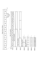
- FIG. 2 is a diagram showing an example of the configuration of a radio frame, a subframe, and a slot used in the radio communication system 10.
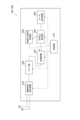
- Figure 3 is a functional block configuration diagram of gNB100 and UE200.
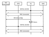
- FIG. 4 is a diagram showing an example of a communication sequence between the UE and the RAN according to the first operation example.
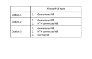
- FIG. 5 is a diagram showing example patterns of types of NTN connectable UE relating to operation example 1.
- FIG. 6 is a diagram showing an example of a communication sequence between the UE and the RAN according to the second operation example.
- FIG. 1 is a schematic diagram showing the overall configuration of a wireless communication system 10.
- FIG. 2 is a diagram showing an example of the configuration of a radio frame, a subframe, and a slot used in the radio communication system 10.
- Figure 3 is a functional block configuration diagram of gNB100 and UE200.
- FIG. 4 is
- FIG. 7 is a diagram showing an example of a communication sequence between a UE and a RAN according to an operation example 2 (dual connectivity connection).
- FIG. 8 is a diagram showing an example of the hardware configuration of gNB100 and UE200.
- FIG. 9 is a diagram showing an example of the configuration of a vehicle 2001.
- FIG. 1 is an overall schematic configuration diagram of a wireless communication system 10 according to this embodiment.
- the wireless communication system 10 is a wireless communication system conforming to a method called Beyond 5G, 5G Evolution, or 6G (hereinafter referred to as 6G), and includes a Radio Access Network 20 (hereinafter referred to as RAN20) and a terminal 200 (User Equipment 200, hereinafter referred to as UE200).
- RAN20 Radio Access Network 20
- UE200 User Equipment 200
- the wireless communication system 10 may be a wireless communication system conforming to a specification other than 6G, such as 5G New Radio (NR).
- NR 5G New Radio
- the RAN 20 includes a radio base station 100 (hereinafter, gNB 100).
- gNB 100 radio base station 100
- the specific configuration of the radio communication system 10, including the number of gNBs and UEs, is not limited to the example shown in FIG. 1.
- the RAN20 actually includes multiple RAN Nodes, specifically, gNBs (or ng-eNBs), and is connected to a core network conforming to 6G.
- the RAN20 and the core network may simply be referred to as a "network.”
- the network formed by the UE200, the RAN20 (including the gNB100), and the core network may also be referred to as a mobile communications network (PLMN: Public Land Mobile Network).
- PLMN Public Land Mobile Network
- the gNB100 is a 6G-compliant radio base station, and performs 6G-compliant wireless communication with the UE200.
- the gNB100 and UE200 are capable of supporting Massive MIMO, which generates more directional beams by controlling radio signals transmitted from multiple antenna elements, Carrier Aggregation (CA), which uses multiple component carriers (CCs) by bundling them together, and Dual Connectivity (DC), which enables simultaneous communication between the UE and multiple NG-RAN nodes.
- Massive MIMO which generates more directional beams by controlling radio signals transmitted from multiple antenna elements
- CA Carrier Aggregation
- CCs component carriers
- DC Dual Connectivity
- the type of DC may be Multi-RAT Dual Connectivity (MR-DC), which uses multiple radio access technologies, or Dual Connectivity, which uses only 6G.
- MR-DC Multi-RAT Dual Connectivity
- one of the gNBs may constitute the master node (MN) and the other gNB may constitute the secondary node (SN).
- MN master node
- SN secondary node
- the wireless communication system 10 may include a non-terrestrial network (hereinafter, NTN).
- NTN non-terrestrial network
- satellite 150 an artificial satellite 150
- services are provided to areas that cannot be covered by a terrestrial network (hereinafter, TN) due to cost and other reasons.
- TN terrestrial network
- NTNs are expected to be applied to IoT (Internet of Things), ships, buses, trains, and critical communications. NTNs also have scalability through efficient multicast or broadcast.
- the radio resources available through an NTN may be more limited (less) than those available through a TN.
- the number of UEs that can be connected through an NTN may be more limited (less) than the number of UEs that can be connected through a TN.
- the satellite 150 may have the functionality of a relay station device, and the relay method may be either a transparent type or a regenerative type.
- a network including a gNB 100 and a UE 200 without including a satellite 150 may be referred to as a TN in contrast to an NTN.
- the UE 200 may communicate with the RAN 20 via the NTN, or may communicate with the RAN 20 via the TN (i.e., without going through the satellite 150).
- satellite 150 may have the functionality of a gNB (wireless base station).
- the type of satellite 150 is not particularly limited, and may be, for example, a geostationary orbit satellite (GEO: Geostationary Orbit satellite) or a low earth orbit satellite (LEO: Low Earth Orbit satellite).
- GEO Geostationary Orbit Satellite
- LEO Low Earth Orbit Satellite
- HAPS High-Altitude Pseudo Satellite
- Satellite 150 is not necessarily limited to these satellites, and may be interpreted as including Spaceborne/Airborne.
- the gNB 100 may include an NTN gateway (not shown).
- the NTN gateway transmits downlink (DL) signals to the satellite 150.
- the NTN gateway receives uplink (UL) signals from the satellite 150.
- Satellite 150 relays the downlink signal received from the NTN gateway to UE 200. Satellite 150 relays the uplink signal received from UE 200 to the NTN gateway. Satellite 150 may be interpreted as a TRP (Transmission-Reception Point), or as a repeater or relay.
- TRP Transmission-Reception Point
- the wireless communication system 10 may support multiple frequency ranges (FR). Specifically, the wireless communication system 10 may support the following FRs:
- FR1 410 MHz to 7.125 GHz
- FR2 ⁇ FR2-1: 24.25 GHz to 52.6 GHz
- FR2-2 Over 52.6GHz to 71GHz FR1 may use a Sub-Carrier Spacing (SCS) of 15, 30 or 60 kHz and a bandwidth (BW) of 5 to 100 MHz.
- SCS Sub-Carrier Spacing
- BW bandwidth
- FR2 is a higher frequency than FR1, and may use a SCS of 60 or 120 kHz (including 240 kHz) and a bandwidth (BW) of 50 to 400 MHz.
- the wireless communication system 10 may also be compatible with frequency bands higher than the FR2 frequency band. Specifically, the wireless communication system 10 may be compatible with frequency bands greater than 52.6 GHz and up to 114.25 GHz.
- Cyclic Prefix-Orthogonal Frequency Division Multiplexing (CP-OFDM)/Discrete Fourier Transform-Spread (DFT-S-OFDM) with larger Sub-Carrier Spacing (SCS) may also be applied.
- DFT-S-OFDM may be applied not only to the uplink (UL) but also to the downlink (DL).
- FIG. 2 shows an example of the configuration of a radio frame, subframe, and slot used in the wireless communication system 10.
- one slot is composed of 14 symbols, and the larger (wider) the SCS, the shorter the symbol period (and slot period).
- the number of symbols constituting one slot does not necessarily have to be 14 symbols (e.g., 28, 56 symbols).
- the number of slots per subframe may differ depending on the SCS.
- the SCS may be wider than 240 kHz (e.g., 480 kHz, 960 kHz as shown in Figure 2).
- time direction (t) shown in Figure 2 may be called the time domain, symbol period, or symbol time.
- the frequency direction may be called the frequency domain, resource block (RB), resource block group (RBG), subcarrier, BWP (Bandwidth part), etc.
- a certain communication quality may simply mean the minimum communication quality that can be guaranteed, but is not necessarily limited to the minimum communication quality. For example, multiple different levels of communication quality may be selectively guaranteed depending on the network conditions, etc., or different levels of communication quality may be guaranteed depending on the capabilities of the UE, etc.
- Guaranteed communication quality may mean that a service with that communication quality can always be enjoyed during the guaranteed period.
- a service with guaranteed communication quality may be interpreted as a service that is the polar opposite of a best-effort service.
- the level of communication quality is not an issue; for example, ultra-reliable and low-latency communication (URLLC) is a best-effort service in which the level of communication quality that can be enjoyed is reasonably high, but the communication quality is not necessarily guaranteed.
- URLLC ultra-reliable and low-latency communication
- the level of communication quality is low, if the communication quality can always be enjoyed, the service can be said to have guaranteed communication quality.
- the content of the communication quality is not particularly limited, but typically includes throughput, latency, and the number of simultaneous UE connections. Furthermore, the communication quality may be guaranteed not only when the mobile communication network is operating normally, but also when the mobile communication network is not operating normally.
- Typical examples of a state in which the mobile communication network is not operating normally include the occurrence of a power outage, a network (equipment) failure, and network congestion due to a concentration of traffic to be processed.
- a state in which the mobile communication network is not operating normally may be interpreted as a state in which available radio resources are more limited (fewer) than in a state in which the mobile communication network is operating normally (first state).
- a UE that is subject to communication quality guarantee may be referred to as a High priority UE.
- High priority UE may also be interpreted as a UE with guaranteed communication quality, a UE requesting communication quality guarantee, a UE with minimum quality guarantee, a Guaranteed UE, or a UE supporting quality guarantee functionality.
- Low priority UEs may also be interpreted as UEs for which communication quality is not guaranteed, UEs that do not request communication quality guarantees, non-guaranteed UEs, or UEs that do not support quality guarantee functions.
- UE200 may operate as a high priority UE or a low priority UE depending on the capability or state of UE200. In other words, whether UE200 is a high priority UE or not may be changed dynamically.
- FIG. 3 is a functional block configuration diagram of the gNB 100 and the UE 200.
- the UE 200 includes a radio signal transmitting/receiving unit 210, an amplifier unit 220, a modulation/demodulation unit 230, a control signal/reference signal processing unit 240, an encoding/decoding unit 250, a data transmitting/receiving unit 260, and a control unit 270.
- FIG. 3 shows only the main functional blocks relevant to the description of the embodiment, and that UE200 (gNB100) has other functional blocks (e.g., a power supply unit, etc.). Also, FIG. 3 shows the functional block configuration of UE200, and for the hardware configuration, please refer to FIG. 8.
- the wireless signal transmitting/receiving unit 210 transmits and receives wireless signals conforming to 6G.
- the wireless signal transmitting/receiving unit 210 can support Massive MIMO, which generates more directional beams by controlling radio frequency (RF) signals transmitted from multiple antenna elements, Carrier Aggregation (CA), which uses multiple component carriers (CC) by bundling them together, and Dual Connectivity (DC), which allows simultaneous communication between a UE and each of two NG-RAN nodes.
- Massive MIMO which generates more directional beams by controlling radio frequency (RF) signals transmitted from multiple antenna elements
- CA Carrier Aggregation
- CC component carriers
- DC Dual Connectivity
- the wireless signal transmitting/receiving unit 210 may perform wireless communication via a mobile communication network in the first state and the second state.
- the wireless signal transmitting/receiving unit 210 may constitute a communication unit.
- the first state may be interpreted as a state in which a specific communication quality in the mobile communication network is guaranteed and the mobile communication network is operating normally.
- the specific communication quality is not particularly limited, but for example, at least one of the following may be specified as a KPI (Key Performance Indicator) related to the minimum quality guarantee. Note that multiple KPIs may be applied in combination.
- ⁇ UE throughput The minimum/maximum value in the communication of the UE, and/or - A statistical value (e.g., CDF (Cumulative Distribution Function) 50%, CDF5% value, etc.).
- CDF Cumulative Distribution Function
- Latency - Minimum/maximum value in the communication of the UE, and/or - Statistical value e.g. CDF50%, CDF5% value, etc.
- Cell capacity total throughput of all UEs in the cell
- - Minimum/maximum values and/or - Statistical values e.g. CDF50%, CDF5% values, etc.
- Reliability - Minimum/maximum value in the communication of the UE, and/or - Statistical value e.g. CDF50%, CDF5% value, etc.
- ⁇ Positioning - The minimum/maximum value of the positioning accuracy of the UE, and/or - Statistical value (e.g.
- the second state may be interpreted as a state in which available wireless resources are more limited than in the first state.
- the wireless signal transceiver 210 may perform wireless communication with the mobile communication network via a normal network available only in the first state and a specific network available in the second state.
- the normal network available only in the first state may be, for example, a terrestrial network (TN), and the specific network available in the second state may be, for example, a non-terrestrial network (NTN).
- TN terrestrial network
- NTN non-terrestrial network
- the NTN has a wide coverage area and is less susceptible to disasters than the TN, and may be prepared as a backup network for situations in which the TN cannot be used due to a failure or the like, or in which the connection of UE200 is restricted.
- the amplifier section 220 is composed of a PA (Power Amplifier)/LNA (Low Noise Amplifier) etc.
- the amplifier section 220 amplifies the signal output from the modem section 230 to a predetermined power level.
- the amplifier section 220 also amplifies the RF signal output from the wireless signal transmission/reception section 210.
- the modem unit 230 performs data modulation/demodulation, transmission power setting, resource block allocation, etc. for each predetermined communication destination (such as gNB100).
- the modem unit 230 may apply Cyclic Prefix-Orthogonal Frequency Division Multiplexing (CP-OFDM)/Discrete Fourier Transform-Spread (DFT-S-OFDM).
- CP-OFDM Cyclic Prefix-Orthogonal Frequency Division Multiplexing
- DFT-S-OFDM Discrete Fourier Transform-Spread
- DFT-S-OFDM may be used not only for the uplink (UL) but also for the downlink (DL).
- the control signal/reference signal processing unit 240 performs processing related to various control signals transmitted and received by the UE 200, and processing related to various reference signals transmitted and received by the UE 200.
- control signal/reference signal processor 240 receives various control signals, such as radio resource control layer (RRC) control signals, transmitted from the gNB 100 via a predetermined control channel.
- RRC radio resource control layer
- the control signal/reference signal processor 240 also transmits various control signals to the gNB 100 via a predetermined control channel.
- the control signal/reference signal processing unit 240 performs processing using reference signals (RS) such as the Demodulation Reference Signal (DMRS) and the Phase Tracking Reference Signal (PTRS).
- RS reference signals
- DMRS Demodulation Reference Signal
- PTRS Phase Tracking Reference Signal
- DMRS is a known reference signal (pilot signal) between the base station and the terminal for each terminal, used to estimate the fading channel used for data demodulation.
- PTRS is a terminal-specific reference signal intended to estimate phase noise, which is an issue in high frequency bands.
- reference signals may also include Channel State Information-Reference Signal (CSI-RS), Sounding Reference Signal (SRS), and Positioning Reference Signal (PRS) for location information.
- CSI-RS Channel State Information-Reference Signal
- SRS Sounding Reference Signal
- PRS Positioning Reference Signal
- Control channels may include control channels and data channels.
- Control channels may include PDCCH (Physical Downlink Control Channel), PUCCH (Physical Uplink Control Channel), RACH (Random Access Channel, Downlink Control Information (DCI) including Random Access Radio Network Temporary Identifier (RA-RNTI)), and Physical Broadcast Channel (PBCH).
- PDCCH Physical Downlink Control Channel
- PUCCH Physical Uplink Control Channel
- RACH Random Access Channel
- DCI Downlink Control Information
- RA-RNTI Random Access Radio Network Temporary Identifier
- PBCH Physical Broadcast Channel
- data channels include PDSCH and PUSCH.
- Data may refer to data transmitted via a data channel.
- control signal/reference signal processing unit 240 may transmit capability information indicating the terminal capabilities of the UE 200 to the network.
- the control signal/reference signal processing unit 240 can transmit UE Capability Information regarding the guarantee of communication quality to the gNB 100.
- control signal/reference signal processing unit 240 may transmit to the gNB 100 UE Capability Information indicating whether or not the UE has the necessary terminal capabilities as a High priority UE, the level of communication quality that can be supported, etc.
- the encoding/decoding unit 250 performs data division/concatenation and channel coding/decoding for each specified communication destination (gNB100 or another gNB).
- the encoding/decoding unit 250 divides the data output from the data transmission/reception unit 260 into pieces of a predetermined size, and performs channel coding on the divided data.
- the encoding/decoding unit 250 also decodes the data output from the modem unit 230, and concatenates the decoded data.
- the data transmission/reception unit 260 transmits and receives Protocol Data Units (PDUs) and Service Data Units (SDUs). Specifically, the data transmission/reception unit 260 performs assembly/disassembly of PDUs/SDUs in multiple layers (such as the Medium Access Control layer (MAC), Radio Link Control layer (RLC), and Packet Data Convergence Protocol layer (PDCP)). The data transmission/reception unit 260 also performs data error correction and retransmission control based on hybrid automatic repeat request (Hybrid ARQ).
- Hybrid ARQ hybrid automatic repeat request
- the control unit 270 controls each functional block constituting the UE 200.
- the control unit 270 can execute control related to guaranteeing a specific communication quality in the mobile communication network.
- the control unit 270 may execute a connection to the mobile communication network only when certain conditions are met.
- the certain conditions may include, for example, the following situations:
- this is the case when UE200 is already connected in the first state to a specific network (e.g., NTN) that is used in the second state. Or, this is the case when UE200 is guaranteed a specific communication quality in the first state (High priority UE).
- a specific network e.g., NTN
- control unit 270 may execute a connection to the mobile communication network in the second state if the UE 200 is already connected to a specific network used in the second state in the first state (a state in which a specific communication quality in the mobile communication network is guaranteed and the mobile communication network is operating normally), or if the UE 200 is subject to a specific communication quality guarantee in the first state.
- control unit 270 may execute a connection to the mobile communication network in the second state if the UE 200 is guaranteed a specific communication quality even in the second state.
- control unit 270 may execute a connection to the mobile communication network in the second state.
- control unit 270 may still perform connection to the mobile communication network in the second state.
- control unit 270 may execute a connection to the mobile communication network only at specific timings.
- the specific timings may include, for example, the following timings:
- a normal network e.g., TN
- a timer that is started after it is recognized that the network is unavailable expires.
- the number of connection attempts may be adjusted according to a certain probability after the timer expires.
- the control unit 270 may also control the execution of dual connectivity (DC) via the TN and NTN.
- the control unit 270 may control the wireless signal transmitting/receiving unit 210 in the first state (a state in which a specific communication quality in the mobile communication network is guaranteed and the mobile communication network is operating normally) to perform wireless communication with the mobile communication network, specifically, to simultaneously connect to the TN and the NTN, via a normal network (e.g., TN) that is available only in the first state, and a specific network (e.g., NTN) that is also available in the second state (a state in which available wireless resources are more limited than in the first state).
- a normal network e.g., TN
- NTN specific network
- control unit 270 may continue wireless communication with the mobile communication network via a specific network (NTN) in the second state.
- NTN specific network
- TN and NTN are described as examples, but the present invention is not necessarily limited to these types of networks.
- a specific network that can be used in the second state may be an ad-hoc network formed using a large zone wireless base station, or an ad-hoc network formed using a mobile wireless base station.
- a normal network that can be used only in the first state is not particularly limited to TN, and may include TN and NTN, or may include networks that are not clearly distinguished from TN or NTN.
- NTN may not necessarily have more limited wireless resources available than TN, and may have more wireless resources available than TN.
- Mission-critical use cases e.g., URLLC
- 5G Mission-critical use cases
- mission-critical communication services are provided using public networks, if the surrounding traffic increases as described above, or if the traffic within the mission-critical communication service increases, it becomes impossible to achieve the desired communication quality (throughput, delay, number of simultaneous connections, etc.).
- NTN non-terrestrial network
- NTN resources are generally more limited than TN resources, so the number of UEs for which quality can be guaranteed is thought to be even more limited. Furthermore, if multiple UEs that require minimum quality guarantees simultaneously issue connection requests (including retries) to the mobile communications network via the NTN, resources may become strained, potentially inducing new failures.
- a system that realizes minimum quality guarantee can be realized by a network operator conditionally guaranteeing a predetermined quality to users based on quality statistics.
- the conditions, the predetermined quality, and the statistics may be assumed as follows.
- the users for whom the minimum quality can be guaranteed are determined for each cell. For example, in cell #1, the minimum quality can be guaranteed only for X people (number of UEs). If the number of users for whom the minimum quality can be guaranteed exceeds the capacity, the minimum quality may not be guaranteed or may not be guaranteed at all.
- the minimum quality guarantee may be guaranteed only when certain areas/reception qualities such as a certain electric field strength (RSRP: Reference Signal Received Power, RSRQ: Reference Signal Received Quality, SINR: Signal-to-Interference plus Noise power Ratio, etc.) are met. For example, areas that are difficult to cover, such as underwater or in the air, may be excluded. In addition, a condition may be that the UE does not enter an environment where radio waves are significantly attenuated, such as entering a room surrounded by twisted lead or covering the antenna with the user's hand.
- RSRP Reference Signal Received Power
- RSRQ Reference Signal Received Quality
- SINR Signal-to-Interference plus Noise power Ratio
- ⁇ (prescribed quality) ⁇ (Proposal 1) The network notifies the UE of the minimum quality that can be guaranteed according to the capability of each UE. For example, for a UE with Reduced UE Capability (RedCap), throughput: XXX bps and delay: XXX ms may be guaranteed, and for an enhanced Mobile Broadband (eMBB) UE (high-end UE), throughput: YYY bps and delay: YYY ms may be guaranteed (YYY ⁇ XXX). UEs for URLLC may also be included.
- RedCap Reduced UE Capability
- eMBB enhanced Mobile Broadband
- YYY bps and delay: YYY ms may be guaranteed (YYY ⁇ XXX).
- UEs for URLLC may also be included.
- ⁇ (Proposal 2) Only quality that can be guaranteed by mandatory capabilities is guaranteed as the minimum quality. For example, it is not always necessary to guarantee 8-layer MIMO x 32CC CA x 1024QAM as the minimum quality. For example, it is possible to guarantee the minimum quality achieved by 4-layer x 1CC x 64QAM.
- ⁇ (Statistical values) It may be guaranteed that the quality statistical values achieved within a specified period are higher than a threshold value. For example, the average throughput over one minute may be guaranteed to be: XXX bps, and the latency: XXX ms.
- UEs that can connect to the NTN may be limited (coexistence with normal UEs). Furthermore, UEs that are subject to the minimum quality guarantee and can connect to the NTN may be limited according to UE capabilities, etc.
- the timing at which the UE executes a connection request to the NTN may be restricted.
- NTN resources are more limited than TN resources, and the number of UEs that can be guaranteed quality is further limited. Therefore, not all UEs that were guaranteed a minimum quality in the TN can be guaranteed the same minimum quality as high priority UEs in the NTN.
- ⁇ (Operation example 1-1) Restrict UE that can connect to NTN (coexistence with normal UE).
- Connection priorities may be defined for UEs that are already connected to NTN, UEs with minimum quality guarantees, and normal UEs.
- Example 1-2 Limit the minimum quality guaranteed UE that can connect to NTN.
- classification may be applied to UEs that are subject to quality guarantees, such as high-priority UEs that are always guaranteed a minimum quality, and UEs that are guaranteed a minimum quality under normal circumstances but not in the event of a failure. Fees may be set according to the class.
- FIG. 4 shows an example of a communication sequence between a UE and a RAN according to the operation example 1.
- a TN which may be called a TN cell
- the UE may perform cell (re)selection to an NTN cell and transmit a connection request (Initial Access).
- the UE may explicitly or implicitly recognize the occurrence of a failure based on at least one of the following events (however, the UE's recognition of the occurrence of a failure does not necessarily constitute a condition for performing the above-mentioned operations):
- the UE may obtain information (which may be called ntn-Config) regarding the configuration of NTN cells surrounding the TN cell through notification information (SIB: System Information Block) from the TN cell.
- SIB System Information Block
- the timing of obtaining the SIB (ntn-Config) does not necessarily have to be the timing shown in Figure 4, and may be, for example, a SIB that can be received before the completion of the RRC connection.
- FIG. 5 shows an example pattern of the types of UEs that can be connected to the NTN in operation example 1.
- restrictions may be placed on the UEs that can be connected to the NTN using any of the following options.
- the UE may be disconnected if it is not a minimum quality guaranteed UE.
- ⁇ (Opt.2) Allow minimum quality guaranteed UE and UE already connected to NTN to use NTN.
- a priority may be set between the lowest quality guaranteed UE and the UE that was originally connected to the NTN. For example, the lowest quality guaranteed UE may be given priority, and the UE that was already connected to the NTN may be excluded depending on the network conditions.
- an indicator may be introduced that indicates a priority according to the UE type, or a priority that is unrelated to the UE type.
- the UE may also transmit information regarding the priority.
- ⁇ (Opt.3) Minimum quality guaranteed UE, UE already connected to NTN, and normal UE are permitted to use NTN.
- Priorities may be set between the lowest quality guaranteed UE, the UE originally connected to the NTN, and the normal UE.
- the lowest quality guaranteed UE may be given priority, and the UE already connected to the NTN and the normal UE may be excluded depending on the network conditions.
- an indicator may be introduced that indicates a priority according to the UE type, or a priority that is unrelated to the UE type.
- the UE may also transmit information regarding the priority.
- the UE may also obtain information (ntn-Config) regarding the configuration of NTN cells surrounding the TN cell through broadcast information (SIB) from the TN cell.
- SIB broadcast information
- ⁇ (Opt.1) Allows the use of NTN for all minimum quality guaranteed UE.
- a classification may be made, for example, into UEs for which the minimum quality is always guaranteed by the NTN and UEs for which the minimum quality is guaranteed only under normal circumstances by the TN.
- the classification method may be included in the minimum quality assurance requirement or permit. Also, a minimum quality assurance requirement for NTN may be required separately from a minimum quality assurance requirement for TN.
- the frequency of the class request may be when requesting a minimum quality guarantee, when reconnecting to the network (e.g. when the UE state changes (RRC IDLE/RRC CONNECTED)), when a related timer expires, on an on-demand basis (e.g. when the service being performed by the UE is switched), or at least a combination of these.
- the frequency of class notification may be when notifying the grant of minimum quality guarantees, upon expiry of an associated timer, on an on-demand basis (e.g. when a request is sent from the UE, when a change is required in the network, etc.), or at least a combination of these.
- ⁇ RAN failure loses coverage of a cell
- ⁇ RAN restriction access attempt is barred
- timer XXX expires The absence of a response from the core network may be determined by the passage of a certain amount of time (timer expiration or excessive retransmission) since the UE transmitted a particular message.
- FIG. 6 shows an example of a communication sequence between a UE and a RAN for operation example 2. As shown in FIG. 6, if a failure occurs in the TN, the UE may limit the timing of requesting a connection to an NTN cell.
- the UE may explicitly/implicitly recognize the occurrence of a failure based on at least one of the following events (however, the UE's recognition of the occurrence of a failure does not necessarily have to be a condition for performing the above-mentioned operation):
- the UE may obtain information (ntn-Config) regarding the configuration of NTN cells surrounding the TN cell through broadcast information (SIB) from the TN cell.
- SIB broadcast information
- the UE may send a connection request via the NTN based on any of the following:
- the UE will send a connection request with a certain probability after a specified timer expires (even if the timer expires, a connection request will be sent with the specified probability).
- ⁇ (Opt.2) Even in the event of a RAN failure, a connection request will be sent after the timer expires.
- the UE may start a timer.
- a connection request may be sent with a certain probability, or a different timer value and/or probability may be set for each UE.
- the timer value may be assumed to be set in advance from the network, may be set to a constant value at all times, or may be set to a variable value each time a retry is performed.
- the UE executes dual connectivity (DC) with the TN and NTN to ensure connection to both networks, and when any of the following events occur, transmits and receives various signals (including reference signals) and data only via the NTN (redundant access path to the RAN).
- DC dual connectivity
- Figure 7 shows an example of a communication sequence between UE and RAN for operation example 2 (dual connectivity connection).
- the UE may explicitly/implicitly recognize the occurrence of a failure based on at least one of the following events (however, the UE's recognition of the occurrence of a failure does not necessarily have to be a condition for performing the above-mentioned operation):
- the UE may obtain information (ntn-Config) regarding the configuration of NTN cells surrounding the TN cell through notification information (SIB) from the TN cell.
- SIB notification information
- the UE may maintain the DC state at all times, or may maintain the DC state for a certain period at regular intervals.
- the UE communicates with the RAN only via the NTN.
- either the operation (Opt.1) or (Opt.2) described above may be applied.
- the UE may operate as follows.
- the cycle and duration of DC may be specified as a timer, or may be instructed by the network through higher layer signaling, etc.
- the UE can limit the timing of requesting a connection to the NTN. This makes it possible to continue to guarantee a certain level of communication quality even if a fault occurs in the mobile communications network and available radio resources are more limited than usual.
- the above-described embodiment is based on the assumption that 6G is used, but the above-described minimum quality assurance mechanism may be provided for wireless communication methods other than 6G, such as 5G/NR.
- configure, activate, update, indicate, enable, specify, and select may be read as interchangeable.
- link, associate, correspond, and map may be read as interchangeable, and allocate, assign, monitor, and map may also be read as interchangeable.
- each functional block may be realized using one device that is physically or logically coupled, or may be realized using two or more devices that are physically or logically separated and connected directly or indirectly (for example, using wires, wirelessly, etc.) and these multiple devices.
- the functional blocks may be realized by combining the one device or the multiple devices with software.
- Functions include, but are not limited to, judgement, determination, judgment, calculation, computation, processing, derivation, investigation, search, confirmation, reception, transmission, output, access, resolution, selection, election, establishment, comparison, assumption, expectation, regard, broadcasting, notifying, communicating, forwarding, configuring, reconfiguring, allocating, mapping, and assignment.
- a functional block (component) that performs the transmission function is called a transmitting unit or transmitter.
- FIG. 8 is a diagram showing an example of the hardware configuration of the device.
- the device may be configured as a computer device including a processor 1001, a memory 1002, a storage 1003, a communication device 1004, an input device 1005, an output device 1006, and a bus 1007.
- apparatus can be interpreted as a circuit, device, unit, etc.
- the hardware configuration of the apparatus may be configured to include one or more of the devices shown in the figure, or may be configured to exclude some of the devices.
- Each functional block of the device (see Figure 3) is realized by any hardware element of the computer device, or a combination of the hardware elements.
- each function of the device is realized by loading a specific software (program) onto hardware such as the processor 1001 and memory 1002, causing the processor 1001 to perform calculations, control communications by the communications device 1004, and control at least one of reading and writing data in the memory 1002 and storage 1003.
- a specific software program
- the processor 1001 for example, runs an operating system to control the entire computer.
- the processor 1001 may be configured as a central processing unit (CPU) that includes an interface with peripheral devices, a control unit, an arithmetic unit, registers, etc.
- CPU central processing unit
- the processor 1001 also reads out programs (program codes), software modules, data, etc. from at least one of the storage 1003 and the communication device 1004 into the memory 1002, and executes various processes according to these.
- the programs used are those that cause a computer to execute at least some of the operations described in the above-mentioned embodiments.
- the various processes described above may be executed by one processor 1001, or may be executed simultaneously or sequentially by two or more processors 1001.
- the processor 1001 may be implemented by one or more chips.
- the programs may be transmitted from a network via a telecommunications line.
- Memory 1002 is a computer-readable recording medium and may be composed of at least one of, for example, Read Only Memory (ROM), Erasable Programmable ROM (EPROM), Electrically Erasable Programmable ROM (EEPROM), Random Access Memory (RAM), etc.
- Memory 1002 may also be called a register, cache, main memory, etc.
- Memory 1002 can store a program (program code), software module, etc. capable of executing a method according to one embodiment of the present disclosure.
- Storage 1003 is a computer-readable recording medium, and may be, for example, at least one of an optical disk such as a Compact Disc ROM (CD-ROM), a hard disk drive, a flexible disk, a magneto-optical disk (e.g., a compact disk, a digital versatile disk, a Blu-ray (registered trademark) disk), a smart card, a flash memory (e.g., a card, a stick, a key drive), a floppy (registered trademark) disk, a magnetic strip, etc.
- Storage 1003 may also be referred to as an auxiliary storage device.
- the above-mentioned recording medium may be, for example, a database, a server, or other suitable medium including at least one of memory 1002 and storage 1003.
- the communication device 1004 is hardware (transmitting/receiving device) for communicating between computers via at least one of a wired network and a wireless network, and is also called, for example, a network device, a network controller, a network card, a communication module, etc.
- the communication device 1004 may be configured to include a high-frequency switch, a duplexer, a filter, a frequency synthesizer, etc., to realize, for example, at least one of Frequency Division Duplex (FDD) and Time Division Duplex (TDD).
- FDD Frequency Division Duplex
- TDD Time Division Duplex
- the input device 1005 is an input device (e.g., a keyboard, a mouse, a microphone, a switch, a button, a sensor, etc.) that accepts input from the outside.
- the output device 1006 is an output device (e.g., a display, a speaker, an LED lamp, etc.) that performs output to the outside. Note that the input device 1005 and the output device 1006 may be integrated into one structure (e.g., a touch panel).
- each device such as the processor 1001 and the memory 1002 is connected by a bus 1007 for communicating information.
- the bus 1007 may be configured using a single bus, or may be configured using different buses between each device.
- the device may be configured to include hardware such as a microprocessor, a digital signal processor (DSP), an application specific integrated circuit (ASIC), a programmable logic device (PLD), or a field programmable gate array (FPGA), and some or all of the functional blocks may be realized by the hardware.
- DSP digital signal processor
- ASIC application specific integrated circuit
- PLD programmable logic device
- FPGA field programmable gate array
- the processor 1001 may be implemented using at least one of these pieces of hardware.
- the notification of information is not limited to the aspects/embodiments described in the present disclosure and may be performed using other methods.
- the notification of information may be performed by physical layer signaling (e.g., Downlink Control Information (DCI), Uplink Control Information (UCI)), higher layer signaling (e.g., RRC signaling, Medium Access Control (MAC) signaling, broadcast information (Master Information Block (MIB), System Information Block (SIB)), other signals, or a combination of these.
- the RRC signaling may be referred to as an RRC message, and may be, for example, an RRC Connection Setup message, an RRC Connection Reconfiguration message, etc.
- LTE Long Term Evolution
- LTE-A LTE-Advanced
- 5G 5th generation mobile communication system
- 6G 6th generation mobile communication system
- xth generation mobile communication system The present invention may be applied to at least one of systems using LTE, LTE-A, LTE-G (xG) (x is, for example, an integer or decimal point), Future Radio Access (FRA), New Radio (NR), W-CDMA (registered trademark), GSM (registered trademark), CDMA2000, Ultra Mobile Broadband (UMB), IEEE 802.11 (Wi-Fi (registered trademark)), IEEE 802.16 (WiMAX (registered trademark)), IEEE 802.20, Ultra-WideBand (UWB), Bluetooth (registered trademark), and other appropriate systems, and next-generation systems that are based on and extend these systems
- certain operations that are described as being performed by a base station may in some cases also be performed by its upper node.
- a network consisting of one or more network nodes having a base station
- various operations performed for communication with a terminal may be performed by at least one of the base station and other network nodes other than the base station (such as, but not limited to, an MME or S-GW).
- the above example shows a case where there is one other network node other than the base station, it may also be a combination of multiple other network nodes (such as an MME and an S-GW).
- Information, signals can be output from a higher layer (or a lower layer) to a lower layer (or a higher layer). They may be input and output via multiple network nodes.
- the input and output information may be stored in a specific location (e.g., memory) or may be managed using a management table.
- the input and output information may be overwritten, updated, or appended.
- the output information may be deleted.
- the input information may be sent to another device.
- the determination may be based on a value represented by one bit (0 or 1), a Boolean value (true or false), or a numerical comparison (e.g., with a predetermined value).
- notification of specific information is not limited to being done explicitly, but may be done implicitly (e.g., not notifying the specific information).
- Software shall be construed broadly to mean instructions, instruction sets, code, code segments, program code, programs, subprograms, software modules, applications, software applications, software packages, routines, subroutines, objects, executable files, threads of execution, procedures, functions, etc., whether referred to as software, firmware, middleware, microcode, hardware description language, or otherwise.
- software, instructions, information, etc. may be transmitted and received over a transmission medium.
- a transmission medium For example, if software is transmitted from a website, server, or other remote source using at least one of wired technologies (such as coaxial cable, fiber optic cable, twisted pair, Digital Subscriber Line (DSL)), and/or wireless technologies (such as infrared, microwave, etc.), then at least one of these wired and/or wireless technologies is included within the definition of a transmission medium.
- wired technologies such as coaxial cable, fiber optic cable, twisted pair, Digital Subscriber Line (DSL)
- wireless technologies such as infrared, microwave, etc.
- the information, signals, etc. described in this disclosure may be represented using any of a variety of different technologies.
- the data, instructions, commands, information, signals, bits, symbols, chips, etc. that may be referred to throughout the above description may be represented by voltages, currents, electromagnetic waves, magnetic fields or magnetic particles, optical fields or photons, or any combination thereof.
- the channel and the symbol may be a signal (signaling).
- the signal may be a message.
- the component carrier (CC) may be called a carrier frequency, a cell, a frequency carrier, etc.
- system and “network” are used interchangeably.
- radio resources may be indicated by an index.
- the names used for the above-mentioned parameters are not limiting in any respect. Furthermore, the formulas etc. using these parameters may differ from those explicitly disclosed in this disclosure.
- the various channels (e.g., PUCCH, PDCCH, etc.) and information elements may be identified by any suitable names, and therefore the various names assigned to these various channels and information elements are not limiting in any respect.
- Base station BS
- wireless base station fixed station
- NodeB NodeB
- eNodeB eNodeB
- gNodeB gNodeB
- a base station can accommodate one or more (e.g., three) cells (also called sectors). If a base station accommodates multiple cells, the overall coverage area of the base station can be divided into multiple smaller areas, and each smaller area can also provide communication services by a base station subsystem (e.g., a small indoor base station (Remote Radio Head: RRH)).
- a base station subsystem e.g., a small indoor base station (Remote Radio Head: RRH)
- cell refers to part or all of the coverage area of a base station and/or a base station subsystem that provides communication services within that coverage.
- a base station transmitting information to a terminal may be interpreted as the base station instructing the terminal to control or operate based on the information.
- MS Mobile Station
- UE User Equipment
- a mobile station may also be referred to by those skilled in the art as a subscriber station, mobile unit, subscriber unit, wireless unit, remote unit, mobile device, wireless device, wireless communication device, remote device, mobile subscriber station, access terminal, mobile terminal, wireless terminal, remote terminal, handset, user agent, mobile client, client, or some other suitable terminology.
- At least one of the base station and the mobile station may be called a transmitting device, a receiving device, a communication device, etc.
- At least one of the base station and the mobile station may be a device mounted on a moving object, or the moving object itself.
- the moving object may be a vehicle (e.g., a car, an airplane, etc.), an unmanned moving object (e.g., a drone, an autonomous vehicle, etc.), or a robot (manned or unmanned).
- At least one of the base station and the mobile station may include a device that does not necessarily move during communication operations.
- at least one of the base station and the mobile station may be an Internet of Things (IoT) device such as a sensor.
- IoT Internet of Things
- the base station in the present disclosure may be interpreted as a mobile station (user terminal, the same applies below).
- each aspect/embodiment of the present disclosure may be applied to a configuration in which communication between a base station and a mobile station is replaced with communication between multiple mobile stations (which may be called, for example, Device-to-Device (D2D), Vehicle-to-Everything (V2X), etc.).
- the mobile station may be configured to have the functions of a base station.
- terms such as "uplink” and "downlink” may be interpreted as terms corresponding to communication between terminals (for example, "side”).
- the uplink channel, downlink channel, etc. may be interpreted as a side channel (or side link).
- the mobile station in this disclosure may be interpreted as a base station.
- the base station may be configured to have the functions of the mobile station.
- a radio frame may be composed of one or more frames in the time domain. Each of the one or more frames in the time domain may be called a subframe. A subframe may further be composed of one or more slots in the time domain. A subframe may have a fixed time length (e.g., 1 ms) that is independent of numerology.
- Numerology may be a communication parameter that applies to at least one of the transmission and reception of a signal or channel. Numerology may indicate, for example, at least one of the following: Subcarrier Spacing (SCS), bandwidth, symbol length, cyclic prefix length, Transmission Time Interval (TTI), number of symbols per TTI, radio frame structure, a particular filtering operation performed by the transceiver in the frequency domain, a particular windowing operation performed by the transceiver in the time domain, etc.
- SCS Subcarrier Spacing
- TTI Transmission Time Interval
- radio frame structure a particular filtering operation performed by the transceiver in the frequency domain, a particular windowing operation performed by the transceiver in the time domain, etc.
- a slot may consist of one or more symbols in the time domain (e.g., Orthogonal Frequency Division Multiplexing (OFDM) symbols, Single Carrier Frequency Division Multiple Access (SC-FDMA) symbols, etc.).
- OFDM Orthogonal Frequency Division Multiplexing
- SC-FDMA Single Carrier Frequency Division Multiple Access
- a slot may be a numerology-based unit of time.
- a slot may include multiple minislots. Each minislot may consist of one or multiple symbols in the time domain. A minislot may also be called a subslot. A minislot may consist of fewer symbols than a slot.
- a PDSCH (or PUSCH) transmitted in a time unit larger than a minislot may be called PDSCH (or PUSCH) mapping type A.
- a PDSCH (or PUSCH) transmitted using a minislot may be called PDSCH (or PUSCH) mapping type B.
- Radio frame, subframe, slot, minislot, and symbol all represent time units for transmitting signals. Radio frame, subframe, slot, minislot, and symbol may each be referred to by a different name that corresponds to the radio frame, subframe, slot, minislot, and symbol.
- one subframe may be called a transmission time interval (TTI)
- TTI transmission time interval
- multiple consecutive subframes may be called a TTI
- one slot or one minislot may be called a TTI.
- at least one of the subframe and the TTI may be a subframe (1 ms) in existing LTE, a period shorter than 1 ms (e.g., 1-13 symbols), or a period longer than 1 ms.
- the unit expressing the TTI may be called a slot, minislot, etc., instead of a subframe.
- TTI refers to, for example, the smallest time unit for scheduling in wireless communication.
- a base station schedules each user terminal by allocating radio resources (such as frequency bandwidth and transmission power that can be used by each user terminal) in TTI units.
- radio resources such as frequency bandwidth and transmission power that can be used by each user terminal
- the TTI may be a transmission time unit for a channel-coded data packet (transport block), a code block, a code word, etc., or may be a processing unit for scheduling, link adaptation, etc.
- the time interval e.g., the number of symbols
- the time interval in which a transport block, a code block, a code word, etc. is actually mapped may be shorter than the TTI.
- one slot or one minislot when called a TTI, one or more TTIs (i.e., one or more slots or one or more minislots) may be the minimum time unit of scheduling.
- the number of slots (minislots) that constitute the minimum time unit of scheduling may be controlled.
- a TTI having a time length of 1 ms may be referred to as a normal TTI (TTI in LTE Rel. 8-12), normal TTI, long TTI, normal subframe, normal subframe, long subframe, slot, etc.
- TTI shorter than a normal TTI may be referred to as a shortened TTI, short TTI, partial or fractional TTI, shortened subframe, short subframe, minislot, subslot, slot, etc.
- a long TTI (e.g., a normal TTI, a subframe, etc.) may be interpreted as a TTI having a time length of more than 1 ms
- a short TTI e.g., a shortened TTI, etc.
- a resource block is a resource allocation unit in the time domain and frequency domain, and may include one or more consecutive subcarriers in the frequency domain.
- the number of subcarriers included in an RB may be the same regardless of the numerology, and may be, for example, 12.
- the number of subcarriers included in an RB may be determined based on the numerology.
- the time domain of an RB may include one or more symbols and may be one slot, one minislot, one subframe, or one TTI in length.
- One TTI, one subframe, etc. may each be composed of one or more resource blocks.
- one or more RBs may also be referred to as a physical resource block (PRB), a sub-carrier group (SCG), a resource element group (REG), a PRB pair, an RB pair, etc.
- PRB physical resource block
- SCG sub-carrier group
- REG resource element group
- PRB pair an RB pair, etc.
- a resource block may be composed of one or more resource elements (RE).
- RE resource elements
- one RE may be a radio resource area of one subcarrier and one symbol.
- a Bandwidth Part which may also be referred to as a partial bandwidth, may represent a subset of contiguous common resource blocks (RBs) for a given numerology on a given carrier, where the common RBs may be identified by the index of the RBs relative to a common reference point of the carriers.
- PRBs may be defined in a BWP and numbered within that BWP.
- the BWP may include a BWP for UL (UL BWP) and a BWP for DL (DL BWP).
- UL BWP UL BWP
- DL BWP DL BWP
- One or more BWPs may be configured for a UE within one carrier.
- At least one of the configured BWPs may be active, and the UE may not expect to transmit or receive a given signal/channel outside the active BWP.
- BWP bitmap
- radio frames, subframes, slots, minislots, and symbols are merely examples.
- the number of subframes included in a radio frame, the number of slots per subframe or radio frame, the number of minislots included in a slot, the number of symbols and RBs included in a slot or minislot, the number of subcarriers included in an RB, as well as the number of symbols in a TTI, the symbol length, the cyclic prefix (CP) length, and other configurations can be changed in various ways.
- connection refers to any direct or indirect connection or coupling between two or more elements, and may include the presence of one or more intermediate elements between two elements that are “connected” or “coupled” to each other.
- the coupling or connection between elements may be physical, logical, or a combination thereof.
- “connected” may be read as "access.”
- two elements may be considered to be “connected” or “coupled” to each other using at least one of one or more wires, cables, and printed electrical connections, as well as electromagnetic energy having wavelengths in the radio frequency range, microwave range, and optical (both visible and invisible) range, as some non-limiting and non-exhaustive examples.
- the reference signal may also be abbreviated as Reference Signal (RS) or referred to as a pilot depending on the applicable standard.
- RS Reference Signal
- the phrase “based on” does not mean “based only on,” unless expressly stated otherwise. In other words, the phrase “based on” means both “based only on” and “based at least on.”
- any reference to elements using designations such as “first,” “second,” etc., used in this disclosure does not generally limit the quantity or order of those elements. These designations may be used in this disclosure as a convenient way of distinguishing between two or more elements. Thus, a reference to a first and a second element does not imply that only two elements may be employed therein or that the first element must precede the second element in some way.
- determining may encompass a wide variety of actions.
- Determining and “determining” may include, for example, judging, calculating, computing, processing, deriving, investigating, looking up, search, inquiry (e.g., searching in a table, database, or other data structure), ascertaining something as “judging” or “determining”, and the like.
- Determining and “determining” may also include receiving (e.g., receiving information), transmitting (e.g., sending information), input, output, accessing (e.g., accessing data in memory), and the like as “judging” or “determining”.
- judgment and “decision” can include considering resolving, selecting, choosing, establishing, comparing, etc., to have been “judged” or “decided.” In other words, “judgment” and “decision” can include considering some action to have been “judged” or “decided.” Additionally, “judgment (decision)” can be interpreted as “assuming,” “expecting,” “considering,” etc.
- a and B are different may mean “A and B are different from each other.”
- the term may also mean “A and B are each different from C.”
- Terms such as “separate” and “combined” may also be interpreted in the same way as “different.”
- FIG. 9 shows an example of the configuration of a vehicle 2001.
- the vehicle 2001 includes a drive unit 2002, a steering unit 2003, an accelerator pedal 2004, a brake pedal 2005, a shift lever 2006, left and right front wheels 2007, left and right rear wheels 2008, an axle 2009, an electronic control unit 2010, various sensors 2021-2029, an information service unit 2012, and a communication module 2013.
- the drive unit 2002 is composed of, for example, an engine, a motor, or a hybrid of an engine and a motor.
- the steering unit 2003 includes at least a steering wheel (also called a handle) and is configured to steer at least one of the front wheels and the rear wheels based on the operation of the steering wheel operated by a user.
- the electronic control unit 2010 is composed of a microprocessor 2031, a memory (ROM, RAM) 2032, and a communication port (IO port) 2033. Signals from various sensors 2021 to 2027 provided in the vehicle are input to the electronic control unit 2010.
- the electronic control unit 2010 may be called an ECU (Electronic Control Unit).
- Signals from the various sensors 2021 to 2028 include a current signal from a current sensor 2021 that senses the current of the motor, a rotation speed signal of the front and rear wheels acquired by a rotation speed sensor 2022, an air pressure signal of the front and rear wheels acquired by an air pressure sensor 2023, a vehicle speed signal acquired by a vehicle speed sensor 2024, an acceleration signal acquired by an acceleration sensor 2025, an accelerator pedal depression amount signal acquired by an accelerator pedal sensor 2029, a brake pedal depression amount signal acquired by a brake pedal sensor 2026, a shift lever operation signal acquired by a shift lever sensor 2027, and a detection signal for detecting obstacles, vehicles, pedestrians, etc. acquired by an object detection sensor 2028.
- the information service unit 2012 is composed of various devices, such as a car navigation system, an audio system, speakers, a television, and a radio, for providing (outputting) various information such as driving information, traffic information, and entertainment information, and one or more ECUs for controlling these devices.
- the information service unit 2012 uses information acquired from external devices via the communication module 2013, etc., to provide various multimedia information and multimedia services to the occupants of the vehicle 1.
- the information service unit 2012 may include input devices (e.g., a keyboard, a mouse, a microphone, a switch, a button, a sensor, a touch panel, etc.) that accept input from the outside, and may also include output devices (e.g., a display, a speaker, an LED lamp, a touch panel, etc.) that perform output to the outside.
- input devices e.g., a keyboard, a mouse, a microphone, a switch, a button, a sensor, a touch panel, etc.
- output devices e.g., a display, a speaker, an LED lamp, a touch panel, etc.
- the driving assistance system unit 2030 is composed of various devices that provide functions for preventing accidents and reducing the driving burden on the driver, such as a millimeter wave radar, LiDAR (Light Detection and Ranging), a camera, a positioning locator (e.g., GNSS, etc.), map information (e.g., high definition (HD) map, autonomous vehicle (AV) map, etc.), a gyro system (e.g., IMU (Inertial Measurement Unit), INS (Inertial Navigation System), etc.), AI (Artificial Intelligence) chip, and an AI processor, as well as one or more ECUs that control these devices.
- the driving assistance system unit 2030 also transmits and receives various information via the communication module 2013 to realize driving assistance functions or autonomous driving functions.
- the communication module 2013 can communicate with the microprocessor 2031 and components of the vehicle 1 via the communication port.
- the communication module 2013 transmits and receives data via the communication port 2033 between the drive unit 2002, steering unit 2003, accelerator pedal 2004, brake pedal 2005, shift lever 2006, left and right front wheels 2007, left and right rear wheels 2008, axle 2009, microprocessor 2031 and memory (ROM, RAM) 2032 in electronic control unit 2010, and sensors 2021 to 2028, which are provided on the vehicle 2001.
- the communication module 2013 is a communication device that can be controlled by the microprocessor 2031 of the electronic control unit 2010 and can communicate with an external device. For example, it transmits and receives various information to and from the external device via wireless communication.
- the communication module 2013 may be located either inside or outside the electronic control unit 2010.
- the external device may be, for example, a base station, a mobile station, etc.
- the communications module 2013 may transmit at least one of the signals from the various sensors 2021-2028 input to the electronic control unit 2010, information obtained based on the signals, and information based on input from the outside (user) obtained via the information service unit 2012 to an external device via wireless communication.
- the electronic control unit 2010, the various sensors 2021-2028, the information service unit 2012, etc. may be referred to as input units that accept input.
- the PUSCH transmitted by the communications module 2013 may include information based on the above input.
- the communication module 2013 receives various information (traffic information, signal information, vehicle distance information, etc.) transmitted from an external device, and displays it on the information service unit 2012 provided in the vehicle.
- the information service unit 2012 may be called an output unit that outputs information (for example, outputs information to a device such as a display or speaker based on the PDSCH (or data/information decoded from the PDSCH) received by the communication module 2013).
- the communication module 2013 also stores various information received from an external device in a memory 2032 that can be used by the microprocessor 2031.
- the microprocessor 2031 may control the drive unit 2002, steering unit 2003, accelerator pedal 2004, brake pedal 2005, shift lever 2006, left and right front wheels 2007, left and right rear wheels 2008, axles 2009, sensors 2021 to 2028, etc. provided in the vehicle 2001.
- a first feature is a terminal including a communication unit that performs wireless communication with a mobile communication network in a first state in which a specific communication quality in a mobile communication network is guaranteed and the mobile communication network operates normally and a second state in which available wireless resources are more limited than in the first state, and a control unit that performs connection with the mobile communication network in the second state only when a specific condition is satisfied.
- the second feature is that in the first feature, the control unit executes a connection to the mobile communication network in the second state if the terminal is already connected to the specific network used in the second state in the first state, or if the terminal is subject to the specific communication quality guarantee in the first state.
- the third feature is that in the first or second feature, if the terminal is subject to the guarantee of the specific communication quality even in the second state, the control unit executes a connection to the mobile communication network in the second state.
- the fourth feature is a terminal that includes a communication unit that performs wireless communication via the mobile communication network in a first state in which a specific communication quality in the mobile communication network is guaranteed and the mobile communication network is operating normally, and a second state in which available wireless resources are more limited than in the first state, and a control unit that performs connection to the mobile communication network only at a specific timing in the second state.
- the fifth feature is the fourth feature, in which the communication unit, in the first state, performs wireless communication with the mobile communication network via a normal network that is only available in the first state and a specific network that is also available in the second state, and the control unit, in the second state, continues wireless communication with the mobile communication network via the specific network.
- Wireless communication system 20 RAN 100 gNB 150 satellites 200 UE 210 Radio signal transmitting/receiving unit 220 Amplifier unit 230 Modulation/demodulation unit 240 Control signal/reference signal processing unit 250 Encoding/decoding unit 260 Data transmitting/receiving unit 270 Control unit 1001 Processor 1002 Memory 1003 Storage 1004 Communication device 1005 Input device 1006 Output device 1007 Bus 2001 Vehicle 2002 Drive unit 2003 Steering unit 2004 Accelerator pedal 2005 Brake pedal 2006 Shift lever 2007 Left and right front wheels 2008 Left and right rear wheels 2009 Axle 2010 Electronic control unit 2012 Information service unit 2013 Communication module 2021 Current sensor 2022 RPM sensor 2023 Air pressure sensor 2024 Vehicle speed sensor 2025 Acceleration sensor 2026 Brake pedal sensor 2027 Shift lever sensor 2028 Object detection sensor 2029 Accelerator pedal sensor 2030 Driving assistance system section 2031 Microprocessor 2032 Memory (ROM, RAM) 2033 communication port
Landscapes
- Engineering & Computer Science (AREA)
- Computer Networks & Wireless Communication (AREA)
- Signal Processing (AREA)
- Physics & Mathematics (AREA)
- Astronomy & Astrophysics (AREA)
- General Physics & Mathematics (AREA)
- Mobile Radio Communication Systems (AREA)
Abstract
Description
図1は、本実施形態に係る無線通信システム10の全体概略構成図である。無線通信システム10は、Beyond 5G、5G Evolution或いは6G(以下、6Gと称呼)と呼ばれる方式に従った無線通信システムであり、Radio Access Network 20(以下、RAN20、及び端末200(User Equipment 200、以下、UE200)を含む。なお、無線通信システム10は、5G New Radio(NR)など、6G以外の仕様に従った無線通信システムでもよい。
・FR2:
・FR2-1:24.25 GHz~52.6 GHz
・FR2-2:52.6GHz超~71GHz
FR1では、15, 30または60kHzのSub-Carrier Spacing(SCS)が用いられ、5~100MHzの帯域幅(BW)が用いられてもよい。FR2は、FR1よりも高周波数であり、60または120kHz(240kHzが含まれてもよい)のSCSが用いられ、50~400MHzの帯域幅(BW)が用いられてもよい。
次に、無線通信システム10の機能ブロック構成について説明する。具体的には、UE200の機能ブロック構成について説明する。図3は、gNB100及びUE200の機能ブロック構成図である。
・当該UEの通信における最低値/最高値、及び/または
・統計的な値(例えば、CDF (Cumulative Distribution Function) 50%、CDF5%値など)。
・当該UEの通信における最低値/最高値、及び/または
・統計的な値(例:CDF50%、CDF5%値など)
・Cell capacity(セル内全UE合計throughput)
・最低値/最高値及び/または
・統計的な値(例:CDF50%、CDF5%値など)
・Reliability
・当該UEの通信における最低値/最高値、及び/または
・統計的な値(例:CDF50%、CDF5%値など)
・Positioning
・当該UEの位置測位精度における最低値/最高値、及び/または
・統計的な値(例:CDF50%、CDF5%値など)
第2状態とは、第1状態よりも利用できる無線リソースが制限された状態と解釈されてよい。無線信号送受信部210は、第1状態において、当該第1状態においてのみ利用可能な通常のネットワークと、第2状態においても利用可能な特定のネットワークを介して移動通信ネットワークとの無線通信を実行してよい。
次に、無線通信システム10の動作について説明する。具体的には、無線通信システム10(移動通信ネットワーク)における通信品質の保証に関する動作について説明する。
上述したように、公衆網を利用するモバイル通信は、「ベストエフォート型」が一般的である。このため、移動通信ネットワークによる通信サービスを提供する通信事業者(ネットワークオペレータ)は、瞬時的なトラフィック量の増加を制御できない。例えば、コンサートなどの密集環境において爆発的にトラフィックが増加すると、最低限の通信品質を担保できなくなる(例えば、電話の発信ができない、ウェブサイトの閲覧もできないなど)。
以下では、上述した課題を解消し得る最低品質保証に関する動作例について説明する。最低品質保証を実現するシステムは、ネットワークオペレータが、品質の統計値に基づいてユーザに対して所定の品質を条件付きで担保することによって実現できる。条件、所定の品質及び統計値は、次のように想定されてよい。
例えば、セル#1ではX人(UE数)のみ最低品質保証が担保されてよい。最低品質を保証できるユーザ数がキャパシティを超えた場合、保証しなくてよい或いは保証できなくてよい。
・(案1):ネットワークは、各UEのCapabilityに応じて担保できる最低品質をUEに通知する。例えば、Reduced UE Capability(RedCap)のUEについては、スループット:XXX bps、遅延:XXX msを担保し、enhanced Mobile Broadband(eMBB)UE(ハイエンドのUE)については、スループット:YYY bps、遅延:YYY msを担保(YYY≧XXX)してもよい。URLLC向けのUEが含まれてもよい。
上述したように、NTNリソースはTNリソースより限定されるため、品質保証できるUEの数がさらに限られる。従って、TNにおいて最低品質が保証されていた全てのUEがNTNでも同様にHigh priority UEとして最低品質の保証を受けられるとは限らない。
図4は、動作例1に係るUE~RAN間の通信シーケンス例を示す。図4に示すように、UEは、TN(TNセルと呼ばれてもよい)に障害が発生した場合、NTNセルに対してセル選択(cell (re)selection)を実行し、接続要求(Initial Access)を送信してよい。
本動作例においても、UEは、TNセルからの報知情報(SIB)によって、当該TNセル周辺のNTNセルの設定に関する情報(ntn-Config)を取得してもよい。
UEがNTNに対して接続を要求する場合、次の何れかのオプションによってNTN接続が可能なUEに制限が設けられてもよい。
本動作例では、TNに障害などが発生した場合、UEは、NTNに対する接続を要求するタイミングを制限してよい。なお、ここでの障害としては、4つのパターンが想定されてよく、それぞれ次のように表現されてもよい。
・RAN規制時: access attempt is barred
・コアネットワーク障害時:timer XXX expires
コアネットワークから応答がないことは、UEが特定のメッセージを送信してから一定時間経過(タイマー満了或いは再送回数超過)によって判定されてよい。
UEからの要求がコアネットワークによって受け付けられないことを意味してよい。
・TNが利用可能な場合、NTNはスタンバイ状態とし、通信には利用しない。
以上、実施形態について説明したが、当該実施形態の記載に限定されるものではなく、種々の変形及び改良が可能であることは、当業者には自明である。
上述した開示は、以下のように表現されてもよい。第1の特徴は、移動通信ネットワークにおける特定の通信品質が保証され、前記移動通信ネットワークが正常に動作している第1状態と、前記第1状態よりも利用できる無線リソースが制限された第2状態とにおいて、前記移動通信ネットワークとの無線通信を実行する通信部と、前記第2状態においては、特定の条件を満たす場合のみ、前記移動通信ネットワークとの接続を実行する制御部とを備える端末である。
20 RAN
100 gNB
150 衛星
200 UE
210 無線信号送受信部
220 アンプ部
230 変復調部
240 制御信号・参照信号処理部
250 符号化/復号部
260 データ送受信部
270 制御部
1001 プロセッサ
1002 メモリ
1003 ストレージ
1004 通信装置
1005 入力装置
1006 出力装置
1007 バス
2001 車両
2002 駆動部
2003 操舵部
2004 アクセルペダル
2005 ブレーキペダル
2006 シフトレバー
2007 左右の前輪
2008 左右の後輪
2009 車軸
2010 電子制御部
2012 情報サービス部
2013 通信モジュール
2021 電流センサ
2022 回転数センサ
2023 空気圧センサ
2024 車速センサ
2025 加速度センサ
2026 ブレーキペダルセンサ
2027 シフトレバーセンサ
2028 物体検出センサ
2029 アクセルペダルセンサ
2030 運転支援システム部
2031 マイクロプロセッサ
2032 メモリ(ROM, RAM)
2033 通信ポート
Claims (6)
- 移動通信ネットワークにおける特定の通信品質が保証され、前記移動通信ネットワークが正常に動作している第1状態と、前記第1状態よりも利用できる無線リソースが制限された第2状態とにおいて、前記移動通信ネットワークとの無線通信を実行する通信部と、
前記第2状態においては、特定の条件を満たす場合のみ、前記移動通信ネットワークとの接続を実行する制御部と
を備える端末。 - 前記制御部は、前記端末が前記第2状態において利用される特定のネットワークに前記第1状態において既に接続していた場合、または前記端末が前記第1状態において前記特定の通信品質の保証対象である場合、前記第2状態において前記移動通信ネットワークとの接続を実行する請求項1に記載の端末。
- 前記制御部は、前記端末が前記第2状態においても前記特定の通信品質の保証対象である場合、前記第2状態において前記移動通信ネットワークとの接続を実行する請求項1に記載の端末。
- 移動通信ネットワークにおける特定の通信品質が保証され、前記移動通信ネットワークが正常に動作している第1状態と、前記第1状態よりも利用できる無線リソースが制限された第2状態とにおいて、前記移動通信ネットワークを経由した無線通信を実行する通信部と、
前記第2状態においては、特定のタイミングにおいてのみ、前記移動通信ネットワークとの接続を実行する制御部と
を備える端末。 - 前記通信部は、前記第1状態において、前記第1状態においてのみ利用可能な通常のネットワークと、前記第2状態においても利用可能な特定のネットワークを介して前記移動通信ネットワークとの無線通信を実行し、
前記制御部は、前記第2状態において、前記特定のネットワークを介して前記移動通信ネットワークとの無線通信を継続する請求項4に記載の端末。 - 移動通信ネットワークにおける特定の通信品質が保証され、前記移動通信ネットワークが正常に動作している第1状態と、前記第1状態よりも利用できる無線リソースが制限された第2状態とにおいて、前記移動通信ネットワークとの無線通信を実行するステップと、
前記第2状態においては、特定の条件を満たす場合のみ、前記移動通信ネットワークとの接続を実行するステップと
を含む端末における無線通信方法。
Priority Applications (3)
| Application Number | Priority Date | Filing Date | Title |
|---|---|---|---|
| JP2025533828A JPWO2025017906A1 (ja) | 2023-07-20 | 2023-07-20 | |
| PCT/JP2023/026612 WO2025017906A1 (ja) | 2023-07-20 | 2023-07-20 | 端末及び無線通信方法 |
| CN202380100536.8A CN121549057A (zh) | 2023-07-20 | 2023-07-20 | 终端以及无线通信方法 |
Applications Claiming Priority (1)
| Application Number | Priority Date | Filing Date | Title |
|---|---|---|---|
| PCT/JP2023/026612 WO2025017906A1 (ja) | 2023-07-20 | 2023-07-20 | 端末及び無線通信方法 |
Publications (1)
| Publication Number | Publication Date |
|---|---|
| WO2025017906A1 true WO2025017906A1 (ja) | 2025-01-23 |
Family
ID=94281394
Family Applications (1)
| Application Number | Title | Priority Date | Filing Date |
|---|---|---|---|
| PCT/JP2023/026612 Ceased WO2025017906A1 (ja) | 2023-07-20 | 2023-07-20 | 端末及び無線通信方法 |
Country Status (3)
| Country | Link |
|---|---|
| JP (1) | JPWO2025017906A1 (ja) |
| CN (1) | CN121549057A (ja) |
| WO (1) | WO2025017906A1 (ja) |
Citations (2)
| Publication number | Priority date | Publication date | Assignee | Title |
|---|---|---|---|---|
| JP2017011341A (ja) * | 2015-06-16 | 2017-01-12 | 三菱電機株式会社 | 地上基地局、移動端末、通信システムおよび通信方法 |
| JP2021036414A (ja) * | 2019-07-25 | 2021-03-04 | 株式会社プロドローン | 遠隔操縦システムおよびその操縦装置 |
-
2023
- 2023-07-20 CN CN202380100536.8A patent/CN121549057A/zh active Pending
- 2023-07-20 JP JP2025533828A patent/JPWO2025017906A1/ja active Pending
- 2023-07-20 WO PCT/JP2023/026612 patent/WO2025017906A1/ja not_active Ceased
Patent Citations (2)
| Publication number | Priority date | Publication date | Assignee | Title |
|---|---|---|---|---|
| JP2017011341A (ja) * | 2015-06-16 | 2017-01-12 | 三菱電機株式会社 | 地上基地局、移動端末、通信システムおよび通信方法 |
| JP2021036414A (ja) * | 2019-07-25 | 2021-03-04 | 株式会社プロドローン | 遠隔操縦システムおよびその操縦装置 |
Non-Patent Citations (1)
| Title |
|---|
| NTT DOCOMO, DOCOMO 6G WHITE PAPER, VERSION 5.0, July 2023 (2023-07-01), Retrieved from the Internet <URL:https://www.docomo.ne.jp/binary/pdf/corporate/technology/whitepaper_6g/DOCOMO_6G_White_PaperJP_20221116.pdf> |
Also Published As
| Publication number | Publication date |
|---|---|
| JPWO2025017906A1 (ja) | 2025-01-23 |
| CN121549057A (zh) | 2026-02-17 |
Similar Documents
| Publication | Publication Date | Title |
|---|---|---|
| WO2023084757A1 (ja) | 端末、基地局、無線通信システム及び無線通信方法 | |
| WO2025017799A1 (ja) | 端末、基地局、無線通信システム及び無線通信方法 | |
| JP7775322B2 (ja) | 端末及び通信方法 | |
| WO2024209632A1 (ja) | 端末、無線通信方法 | |
| WO2024171411A1 (ja) | 端末及び通信方法 | |
| CN121549057A (zh) | 终端以及无线通信方法 | |
| WO2024209700A1 (ja) | 端末及び無線通信方法 | |
| WO2025022590A1 (ja) | 端末及び無線通信方法 | |
| WO2025017847A1 (ja) | 端末、無線基地局及び無線通信方法 | |
| WO2025022588A1 (ja) | 端末及び無線通信方法 | |
| WO2025017845A1 (ja) | 端末及び無線通信方法 | |
| WO2024209559A1 (ja) | 端末及び無線通信方法 | |
| WO2025017844A1 (ja) | 端末、無線基地局及び無線通信方法 | |
| WO2025017846A1 (ja) | 端末、無線基地局及び無線通信方法 | |
| WO2024161661A1 (ja) | 端末 | |
| WO2024161663A1 (ja) | 端末 | |
| WO2024161660A1 (ja) | 端末 | |
| WO2024075299A1 (ja) | 端末 | |
| WO2026018343A1 (ja) | 端末、基地局、無線通信システム及び無線通信方法 | |
| WO2025017887A1 (ja) | 端末、基地局、無線通信システム及び無線通信方法 | |
| WO2025017885A1 (ja) | 端末、基地局、無線通信システム及び無線通信方法 | |
| WO2025022589A1 (ja) | 端末、基地局、無線通信システム及び無線通信方法 | |
| WO2024095483A1 (ja) | 端末、基地局、無線通信システム及び無線通信方法 | |
| WO2025037407A1 (ja) | 端末 | |
| WO2024034094A1 (ja) | 端末及び無線通信方法 |
Legal Events
| Date | Code | Title | Description |
|---|---|---|---|
| 121 | Ep: the epo has been informed by wipo that ep was designated in this application |
Ref document number: 23945908 Country of ref document: EP Kind code of ref document: A1 |
|
| ENP | Entry into the national phase |
Ref document number: 2025533828 Country of ref document: JP Kind code of ref document: A |
|
| WWE | Wipo information: entry into national phase |
Ref document number: 2025533828 Country of ref document: JP |
|
| WWE | Wipo information: entry into national phase |
Ref document number: 2023945908 Country of ref document: EP |
|
| NENP | Non-entry into the national phase |
Ref country code: DE |