WO2025017797A1 - 熱管理システム - Google Patents
熱管理システム Download PDFInfo
- Publication number
- WO2025017797A1 WO2025017797A1 PCT/JP2023/026118 JP2023026118W WO2025017797A1 WO 2025017797 A1 WO2025017797 A1 WO 2025017797A1 JP 2023026118 W JP2023026118 W JP 2023026118W WO 2025017797 A1 WO2025017797 A1 WO 2025017797A1
- Authority
- WO
- WIPO (PCT)
- Prior art keywords
- heat exchange
- heat
- electrical equipment
- exchange passage
- passage
- Prior art date
- Legal status (The legal status is an assumption and is not a legal conclusion. Google has not performed a legal analysis and makes no representation as to the accuracy of the status listed.)
- Ceased
Links
Images








Classifications
-
- B—PERFORMING OPERATIONS; TRANSPORTING
- B60—VEHICLES IN GENERAL
- B60H—ARRANGEMENTS OF HEATING, COOLING, VENTILATING OR OTHER AIR-TREATING DEVICES SPECIALLY ADAPTED FOR PASSENGER OR GOODS SPACES OF VEHICLES
- B60H1/00—Heating, cooling or ventilating devices
- B60H1/00271—HVAC devices specially adapted for particular vehicle parts or components and being connected to the vehicle HVAC unit
- B60H1/00278—HVAC devices specially adapted for particular vehicle parts or components and being connected to the vehicle HVAC unit for the battery
-
- B—PERFORMING OPERATIONS; TRANSPORTING
- B60—VEHICLES IN GENERAL
- B60H—ARRANGEMENTS OF HEATING, COOLING, VENTILATING OR OTHER AIR-TREATING DEVICES SPECIALLY ADAPTED FOR PASSENGER OR GOODS SPACES OF VEHICLES
- B60H1/00—Heating, cooling or ventilating devices
-
- B—PERFORMING OPERATIONS; TRANSPORTING
- B60—VEHICLES IN GENERAL
- B60K—ARRANGEMENT OR MOUNTING OF PROPULSION UNITS OR OF TRANSMISSIONS IN VEHICLES; ARRANGEMENT OR MOUNTING OF PLURAL DIVERSE PRIME-MOVERS IN VEHICLES; AUXILIARY DRIVES FOR VEHICLES; INSTRUMENTATION OR DASHBOARDS FOR VEHICLES; ARRANGEMENTS IN CONNECTION WITH COOLING, AIR INTAKE, GAS EXHAUST OR FUEL SUPPLY OF PROPULSION UNITS IN VEHICLES
- B60K1/00—Arrangement or mounting of electrical propulsion units
- B60K1/04—Arrangement or mounting of electrical propulsion units of the electric storage means for propulsion
-
- B—PERFORMING OPERATIONS; TRANSPORTING
- B60—VEHICLES IN GENERAL
- B60K—ARRANGEMENT OR MOUNTING OF PROPULSION UNITS OR OF TRANSMISSIONS IN VEHICLES; ARRANGEMENT OR MOUNTING OF PLURAL DIVERSE PRIME-MOVERS IN VEHICLES; AUXILIARY DRIVES FOR VEHICLES; INSTRUMENTATION OR DASHBOARDS FOR VEHICLES; ARRANGEMENTS IN CONNECTION WITH COOLING, AIR INTAKE, GAS EXHAUST OR FUEL SUPPLY OF PROPULSION UNITS IN VEHICLES
- B60K11/00—Arrangement in connection with cooling of propulsion units
- B60K11/02—Arrangement in connection with cooling of propulsion units with liquid cooling
-
- B—PERFORMING OPERATIONS; TRANSPORTING
- B60—VEHICLES IN GENERAL
- B60L—PROPULSION OF ELECTRICALLY-PROPELLED VEHICLES; SUPPLYING ELECTRIC POWER FOR AUXILIARY EQUIPMENT OF ELECTRICALLY-PROPELLED VEHICLES; ELECTRODYNAMIC BRAKE SYSTEMS FOR VEHICLES IN GENERAL; MAGNETIC SUSPENSION OR LEVITATION FOR VEHICLES; MONITORING OPERATING VARIABLES OF ELECTRICALLY-PROPELLED VEHICLES; ELECTRIC SAFETY DEVICES FOR ELECTRICALLY-PROPELLED VEHICLES
- B60L1/00—Supplying electric power to auxiliary equipment of vehicles
- B60L1/003—Supplying electric power to auxiliary equipment of vehicles to auxiliary motors, e.g. for pumps, compressors
-
- B—PERFORMING OPERATIONS; TRANSPORTING
- B60—VEHICLES IN GENERAL
- B60L—PROPULSION OF ELECTRICALLY-PROPELLED VEHICLES; SUPPLYING ELECTRIC POWER FOR AUXILIARY EQUIPMENT OF ELECTRICALLY-PROPELLED VEHICLES; ELECTRODYNAMIC BRAKE SYSTEMS FOR VEHICLES IN GENERAL; MAGNETIC SUSPENSION OR LEVITATION FOR VEHICLES; MONITORING OPERATING VARIABLES OF ELECTRICALLY-PROPELLED VEHICLES; ELECTRIC SAFETY DEVICES FOR ELECTRICALLY-PROPELLED VEHICLES
- B60L1/00—Supplying electric power to auxiliary equipment of vehicles
- B60L1/02—Supplying electric power to auxiliary equipment of vehicles to electric heating circuits
-
- B—PERFORMING OPERATIONS; TRANSPORTING
- B60—VEHICLES IN GENERAL
- B60L—PROPULSION OF ELECTRICALLY-PROPELLED VEHICLES; SUPPLYING ELECTRIC POWER FOR AUXILIARY EQUIPMENT OF ELECTRICALLY-PROPELLED VEHICLES; ELECTRODYNAMIC BRAKE SYSTEMS FOR VEHICLES IN GENERAL; MAGNETIC SUSPENSION OR LEVITATION FOR VEHICLES; MONITORING OPERATING VARIABLES OF ELECTRICALLY-PROPELLED VEHICLES; ELECTRIC SAFETY DEVICES FOR ELECTRICALLY-PROPELLED VEHICLES
- B60L3/00—Electric devices on electrically-propelled vehicles for safety purposes; Monitoring operating variables, e.g. speed, deceleration or energy consumption
- B60L3/0023—Detecting, eliminating, remedying or compensating for drive train abnormalities, e.g. failures within the drive train
- B60L3/003—Detecting, eliminating, remedying or compensating for drive train abnormalities, e.g. failures within the drive train relating to inverters
-
- B—PERFORMING OPERATIONS; TRANSPORTING
- B60—VEHICLES IN GENERAL
- B60L—PROPULSION OF ELECTRICALLY-PROPELLED VEHICLES; SUPPLYING ELECTRIC POWER FOR AUXILIARY EQUIPMENT OF ELECTRICALLY-PROPELLED VEHICLES; ELECTRODYNAMIC BRAKE SYSTEMS FOR VEHICLES IN GENERAL; MAGNETIC SUSPENSION OR LEVITATION FOR VEHICLES; MONITORING OPERATING VARIABLES OF ELECTRICALLY-PROPELLED VEHICLES; ELECTRIC SAFETY DEVICES FOR ELECTRICALLY-PROPELLED VEHICLES
- B60L50/00—Electric propulsion with power supplied within the vehicle
- B60L50/50—Electric propulsion with power supplied within the vehicle using propulsion power supplied by batteries or fuel cells
- B60L50/60—Electric propulsion with power supplied within the vehicle using propulsion power supplied by batteries or fuel cells using power supplied by batteries
- B60L50/64—Constructional details of batteries specially adapted for electric vehicles
-
- B—PERFORMING OPERATIONS; TRANSPORTING
- B60—VEHICLES IN GENERAL
- B60L—PROPULSION OF ELECTRICALLY-PROPELLED VEHICLES; SUPPLYING ELECTRIC POWER FOR AUXILIARY EQUIPMENT OF ELECTRICALLY-PROPELLED VEHICLES; ELECTRODYNAMIC BRAKE SYSTEMS FOR VEHICLES IN GENERAL; MAGNETIC SUSPENSION OR LEVITATION FOR VEHICLES; MONITORING OPERATING VARIABLES OF ELECTRICALLY-PROPELLED VEHICLES; ELECTRIC SAFETY DEVICES FOR ELECTRICALLY-PROPELLED VEHICLES
- B60L50/00—Electric propulsion with power supplied within the vehicle
- B60L50/50—Electric propulsion with power supplied within the vehicle using propulsion power supplied by batteries or fuel cells
- B60L50/60—Electric propulsion with power supplied within the vehicle using propulsion power supplied by batteries or fuel cells using power supplied by batteries
- B60L50/66—Arrangements of batteries
-
- B—PERFORMING OPERATIONS; TRANSPORTING
- B60—VEHICLES IN GENERAL
- B60L—PROPULSION OF ELECTRICALLY-PROPELLED VEHICLES; SUPPLYING ELECTRIC POWER FOR AUXILIARY EQUIPMENT OF ELECTRICALLY-PROPELLED VEHICLES; ELECTRODYNAMIC BRAKE SYSTEMS FOR VEHICLES IN GENERAL; MAGNETIC SUSPENSION OR LEVITATION FOR VEHICLES; MONITORING OPERATING VARIABLES OF ELECTRICALLY-PROPELLED VEHICLES; ELECTRIC SAFETY DEVICES FOR ELECTRICALLY-PROPELLED VEHICLES
- B60L58/00—Methods or circuit arrangements for monitoring or controlling batteries or fuel cells, specially adapted for electric vehicles
- B60L58/10—Methods or circuit arrangements for monitoring or controlling batteries or fuel cells, specially adapted for electric vehicles for monitoring or controlling batteries
- B60L58/24—Methods or circuit arrangements for monitoring or controlling batteries or fuel cells, specially adapted for electric vehicles for monitoring or controlling batteries for controlling the temperature of batteries
- B60L58/26—Methods or circuit arrangements for monitoring or controlling batteries or fuel cells, specially adapted for electric vehicles for monitoring or controlling batteries for controlling the temperature of batteries by cooling
-
- B—PERFORMING OPERATIONS; TRANSPORTING
- B60—VEHICLES IN GENERAL
- B60L—PROPULSION OF ELECTRICALLY-PROPELLED VEHICLES; SUPPLYING ELECTRIC POWER FOR AUXILIARY EQUIPMENT OF ELECTRICALLY-PROPELLED VEHICLES; ELECTRODYNAMIC BRAKE SYSTEMS FOR VEHICLES IN GENERAL; MAGNETIC SUSPENSION OR LEVITATION FOR VEHICLES; MONITORING OPERATING VARIABLES OF ELECTRICALLY-PROPELLED VEHICLES; ELECTRIC SAFETY DEVICES FOR ELECTRICALLY-PROPELLED VEHICLES
- B60L58/00—Methods or circuit arrangements for monitoring or controlling batteries or fuel cells, specially adapted for electric vehicles
- B60L58/10—Methods or circuit arrangements for monitoring or controlling batteries or fuel cells, specially adapted for electric vehicles for monitoring or controlling batteries
- B60L58/24—Methods or circuit arrangements for monitoring or controlling batteries or fuel cells, specially adapted for electric vehicles for monitoring or controlling batteries for controlling the temperature of batteries
- B60L58/27—Methods or circuit arrangements for monitoring or controlling batteries or fuel cells, specially adapted for electric vehicles for monitoring or controlling batteries for controlling the temperature of batteries by heating
-
- B—PERFORMING OPERATIONS; TRANSPORTING
- B60—VEHICLES IN GENERAL
- B60H—ARRANGEMENTS OF HEATING, COOLING, VENTILATING OR OTHER AIR-TREATING DEVICES SPECIALLY ADAPTED FOR PASSENGER OR GOODS SPACES OF VEHICLES
- B60H1/00—Heating, cooling or ventilating devices
- B60H1/00271—HVAC devices specially adapted for particular vehicle parts or components and being connected to the vehicle HVAC unit
- B60H2001/003—Component temperature regulation using an air flow
-
- B—PERFORMING OPERATIONS; TRANSPORTING
- B60—VEHICLES IN GENERAL
- B60H—ARRANGEMENTS OF HEATING, COOLING, VENTILATING OR OTHER AIR-TREATING DEVICES SPECIALLY ADAPTED FOR PASSENGER OR GOODS SPACES OF VEHICLES
- B60H1/00—Heating, cooling or ventilating devices
- B60H1/00271—HVAC devices specially adapted for particular vehicle parts or components and being connected to the vehicle HVAC unit
- B60H2001/00307—Component temperature regulation using a liquid flow
-
- B—PERFORMING OPERATIONS; TRANSPORTING
- B60—VEHICLES IN GENERAL
- B60K—ARRANGEMENT OR MOUNTING OF PROPULSION UNITS OR OF TRANSMISSIONS IN VEHICLES; ARRANGEMENT OR MOUNTING OF PLURAL DIVERSE PRIME-MOVERS IN VEHICLES; AUXILIARY DRIVES FOR VEHICLES; INSTRUMENTATION OR DASHBOARDS FOR VEHICLES; ARRANGEMENTS IN CONNECTION WITH COOLING, AIR INTAKE, GAS EXHAUST OR FUEL SUPPLY OF PROPULSION UNITS IN VEHICLES
- B60K1/00—Arrangement or mounting of electrical propulsion units
- B60K2001/003—Arrangement or mounting of electrical propulsion units with means for cooling the electrical propulsion units
- B60K2001/005—Arrangement or mounting of electrical propulsion units with means for cooling the electrical propulsion units the electric storage means
-
- B—PERFORMING OPERATIONS; TRANSPORTING
- B60—VEHICLES IN GENERAL
- B60L—PROPULSION OF ELECTRICALLY-PROPELLED VEHICLES; SUPPLYING ELECTRIC POWER FOR AUXILIARY EQUIPMENT OF ELECTRICALLY-PROPELLED VEHICLES; ELECTRODYNAMIC BRAKE SYSTEMS FOR VEHICLES IN GENERAL; MAGNETIC SUSPENSION OR LEVITATION FOR VEHICLES; MONITORING OPERATING VARIABLES OF ELECTRICALLY-PROPELLED VEHICLES; ELECTRIC SAFETY DEVICES FOR ELECTRICALLY-PROPELLED VEHICLES
- B60L2240/00—Control parameters of input or output; Target parameters
- B60L2240/10—Vehicle control parameters
- B60L2240/34—Cabin temperature
-
- B—PERFORMING OPERATIONS; TRANSPORTING
- B60—VEHICLES IN GENERAL
- B60L—PROPULSION OF ELECTRICALLY-PROPELLED VEHICLES; SUPPLYING ELECTRIC POWER FOR AUXILIARY EQUIPMENT OF ELECTRICALLY-PROPELLED VEHICLES; ELECTRODYNAMIC BRAKE SYSTEMS FOR VEHICLES IN GENERAL; MAGNETIC SUSPENSION OR LEVITATION FOR VEHICLES; MONITORING OPERATING VARIABLES OF ELECTRICALLY-PROPELLED VEHICLES; ELECTRIC SAFETY DEVICES FOR ELECTRICALLY-PROPELLED VEHICLES
- B60L2240/00—Control parameters of input or output; Target parameters
- B60L2240/10—Vehicle control parameters
- B60L2240/36—Temperature of vehicle components or parts
-
- B—PERFORMING OPERATIONS; TRANSPORTING
- B60—VEHICLES IN GENERAL
- B60L—PROPULSION OF ELECTRICALLY-PROPELLED VEHICLES; SUPPLYING ELECTRIC POWER FOR AUXILIARY EQUIPMENT OF ELECTRICALLY-PROPELLED VEHICLES; ELECTRODYNAMIC BRAKE SYSTEMS FOR VEHICLES IN GENERAL; MAGNETIC SUSPENSION OR LEVITATION FOR VEHICLES; MONITORING OPERATING VARIABLES OF ELECTRICALLY-PROPELLED VEHICLES; ELECTRIC SAFETY DEVICES FOR ELECTRICALLY-PROPELLED VEHICLES
- B60L2240/00—Control parameters of input or output; Target parameters
- B60L2240/40—Drive Train control parameters
- B60L2240/42—Drive Train control parameters related to electric machines
- B60L2240/425—Temperature
-
- B—PERFORMING OPERATIONS; TRANSPORTING
- B60—VEHICLES IN GENERAL
- B60L—PROPULSION OF ELECTRICALLY-PROPELLED VEHICLES; SUPPLYING ELECTRIC POWER FOR AUXILIARY EQUIPMENT OF ELECTRICALLY-PROPELLED VEHICLES; ELECTRODYNAMIC BRAKE SYSTEMS FOR VEHICLES IN GENERAL; MAGNETIC SUSPENSION OR LEVITATION FOR VEHICLES; MONITORING OPERATING VARIABLES OF ELECTRICALLY-PROPELLED VEHICLES; ELECTRIC SAFETY DEVICES FOR ELECTRICALLY-PROPELLED VEHICLES
- B60L2240/00—Control parameters of input or output; Target parameters
- B60L2240/40—Drive Train control parameters
- B60L2240/52—Drive Train control parameters related to converters
- B60L2240/525—Temperature of converter or components thereof
-
- B—PERFORMING OPERATIONS; TRANSPORTING
- B60—VEHICLES IN GENERAL
- B60L—PROPULSION OF ELECTRICALLY-PROPELLED VEHICLES; SUPPLYING ELECTRIC POWER FOR AUXILIARY EQUIPMENT OF ELECTRICALLY-PROPELLED VEHICLES; ELECTRODYNAMIC BRAKE SYSTEMS FOR VEHICLES IN GENERAL; MAGNETIC SUSPENSION OR LEVITATION FOR VEHICLES; MONITORING OPERATING VARIABLES OF ELECTRICALLY-PROPELLED VEHICLES; ELECTRIC SAFETY DEVICES FOR ELECTRICALLY-PROPELLED VEHICLES
- B60L2240/00—Control parameters of input or output; Target parameters
- B60L2240/40—Drive Train control parameters
- B60L2240/54—Drive Train control parameters related to batteries
- B60L2240/545—Temperature
-
- B—PERFORMING OPERATIONS; TRANSPORTING
- B60—VEHICLES IN GENERAL
- B60L—PROPULSION OF ELECTRICALLY-PROPELLED VEHICLES; SUPPLYING ELECTRIC POWER FOR AUXILIARY EQUIPMENT OF ELECTRICALLY-PROPELLED VEHICLES; ELECTRODYNAMIC BRAKE SYSTEMS FOR VEHICLES IN GENERAL; MAGNETIC SUSPENSION OR LEVITATION FOR VEHICLES; MONITORING OPERATING VARIABLES OF ELECTRICALLY-PROPELLED VEHICLES; ELECTRIC SAFETY DEVICES FOR ELECTRICALLY-PROPELLED VEHICLES
- B60L2240/00—Control parameters of input or output; Target parameters
- B60L2240/60—Navigation input
- B60L2240/66—Ambient conditions
- B60L2240/662—Temperature
-
- Y—GENERAL TAGGING OF NEW TECHNOLOGICAL DEVELOPMENTS; GENERAL TAGGING OF CROSS-SECTIONAL TECHNOLOGIES SPANNING OVER SEVERAL SECTIONS OF THE IPC; TECHNICAL SUBJECTS COVERED BY FORMER USPC CROSS-REFERENCE ART COLLECTIONS [XRACs] AND DIGESTS
- Y02—TECHNOLOGIES OR APPLICATIONS FOR MITIGATION OR ADAPTATION AGAINST CLIMATE CHANGE
- Y02E—REDUCTION OF GREENHOUSE GAS [GHG] EMISSIONS, RELATED TO ENERGY GENERATION, TRANSMISSION OR DISTRIBUTION
- Y02E60/00—Enabling technologies; Technologies with a potential or indirect contribution to GHG emissions mitigation
- Y02E60/10—Energy storage using batteries
Definitions
- the present invention relates to a thermal management system.
- Patent Document 1 discloses a thermal management system having a high-temperature heat medium circuit, a low-temperature heat medium circuit, and an equipment heat medium circuit.
- the thermal management system disclosed in Patent Document 1 includes a circuit switching unit that switches the flow of the heat medium.
- This circuit switching unit includes multiple open valves and multiple on-off valves.
- the thermal management system disclosed in Patent Document 1 determines the circuit through which the heat medium flows by combining the control of multiple three-way valves and the control of multiple open valves.
- the thermal management system disclosed in Patent Document 1 requires a complex structure including multiple three-way valves and multiple on-off valves to change the flow path through which the heat medium flows.
- the thermal management system disclosed in Patent Document 1 requires the control of multiple three-way valves and multiple on-off valves, making the control complex.
- the present invention was made in consideration of the above-mentioned problems, and aims to make it possible to change the flow path through which the heat transfer medium for heat management is guided with a simple structure in a thermal management system installed in a vehicle.
- the present invention adopts the following configuration as a means for solving the above problems.
- One aspect of the present invention is a thermal management system that is mounted on a vehicle and performs thermal management of thermally managed objects including electrical equipment, and is configured to include an electrical equipment heat exchange flow path that guides a heat medium for heat management to pass through the electrical equipment, an outside air heat exchange flow path that guides the heat medium for heat management to pass through an outside air heat exchanger that exchanges heat between outside air and the heat medium for heat management, a battery heat exchange flow path that guides the heat medium for heat management to pass through a battery, and a switching valve that is arranged at a connection between the electrical equipment heat exchange flow path, the outside air heat exchange flow path, and the battery heat exchange flow path and that can switch the direction of the heat medium for heat management to the electrical equipment heat exchange flow path, the outside air heat exchange flow path, and the battery heat exchange flow path.
- the present invention is capable of changing the connection state between the electrical equipment heat exchange path, the outside air heat exchange path, and the battery heat exchange path by controlling a switching valve arranged at the connection portion between the electrical equipment heat exchange path, the outside air heat exchange path, and the battery heat exchange path. Therefore, the present invention is capable of changing the path of the heat management heat medium without using multiple three-way valves and multiple opening and closing valves. Therefore, the present invention can change the path through which the heat management heat medium is guided with a simple structure in a thermal management system mounted on a vehicle.
- FIG. 1 is a schematic configuration diagram of a vehicle equipped with a thermal management system according to a first embodiment of the present invention.
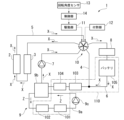
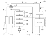
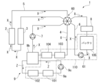
- 1 is a system configuration diagram showing a schematic configuration of a thermal management system according to a first embodiment of the present invention
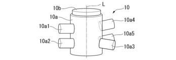
- 1 is a schematic perspective view of a five-way valve provided in a thermal management system according to a first embodiment of the present invention.
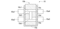
- FIG. 1 is a schematic vertical cross-sectional view of a five-way valve provided in a thermal management system according to a first embodiment of the present invention.
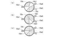
- FIG. FIG. 2 is a schematic cross-sectional view of a five-way valve in a first connection mode of the thermal management system in the first embodiment of the present invention;
- FIG. 2 is a schematic diagram showing a flow of a heat medium for thermal management in a first connection mode of the thermal management system according to the first embodiment of the present invention.
- FIG. 2 is a schematic cross-sectional view of the five-way valve in a second connection mode of the thermal management system in the first embodiment of the present invention;
- FIG. 4 is a schematic diagram showing the flow of a heat medium for thermal management in a second connection mode of the thermal management system in the first embodiment of the present invention.
- FIG. 2 is a schematic cross-sectional view of the five-way valve in a third connection mode of the thermal management system in the first embodiment of the present invention;
- FIG. 4 is a schematic diagram showing the flow of a heat medium for thermal management in a third connection mode of the thermal management system in the first embodiment of the present invention.
- FIG. 2 is a schematic cross-sectional view of the five-way valve in a fourth connection mode of the thermal management system in the first embodiment of the present invention;
- FIG. 11 is a schematic diagram showing the flow of a heat medium for thermal management in a fourth connection mode of the thermal management system according to the first embodiment of the present invention.
- 1 is a schematic perspective view including a driving unit, a biasing unit, and a rotation angle sensor included in a thermal management system according to a first embodiment of the present invention.
- 1 is a system configuration diagram showing a schematic configuration of an example of an in-vehicle air conditioning system;
- FIG. 1 is a system configuration diagram showing a schematic configuration of an example of an in-vehicle air conditioning system;
- FIG. 11 is a system configuration diagram showing a schematic configuration of a thermal management system according to a second embodiment of the present invention.
- FIG. 11 is a schematic perspective view of a five-way valve provided in a thermal management system according to a second embodiment of the present invention.
- FIG. 6 is a schematic vertical cross-sectional view of a five-way valve provided in a thermal management system according to a second embodiment of the present invention.
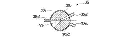
- FIG. 11 is a schematic cross-sectional view of a four-way valve in a fifth connection mode of a thermal management system according to a second embodiment of the present invention;
- FIG. 11 is a schematic diagram showing the flow of a heat medium for thermal management in a fifth connection mode of the thermal management system according to the second embodiment of the present invention.
- FIG. 11 is a system configuration diagram showing a schematic configuration of a thermal management system according to a second embodiment of the present invention.
- FIG. 11 is a schematic perspective view of a five-way valve provided in a thermal management system according to
- FIG. 11 is a schematic cross-sectional view of a four-way valve in a sixth connection mode of the thermal management system in the second embodiment of the present invention
- FIG. 11 is a schematic diagram showing the flow of a heat medium for thermal management in a sixth connection mode of the thermal management system according to the second embodiment of the present invention.
- FIG. 13 is a schematic cross-sectional view of a four-way valve in a seventh connection mode of the thermal management system according to the second embodiment of the present invention;
- FIG. 11 is a schematic diagram showing the flow of a heat medium for thermal management in a seventh connection mode of the thermal management system according to the second embodiment of the present invention.
- FIG. 13 is a schematic cross-sectional view of a four-way valve in an eighth connection mode of a thermal management system according to a second embodiment of the present invention
- FIG. 11 is a schematic diagram showing the flow of a heat medium for thermal management in an eighth connection mode of the thermal management system according to the second embodiment of the present invention.
- FIG. 2 is a system configuration diagram showing a schematic configuration of a modified example of the thermal management system in the first embodiment of the present invention.
- FIG. 1 is a schematic diagram of a vehicle 100 equipped with a thermal management system 1 according to the present embodiment.
- the vehicle 100 is, for example, an electric vehicle.
- the vehicle 100 may also be a so-called hybrid vehicle equipped with an internal combustion engine and a traction motor.
- the vehicle 100 includes a traction motor 101, an inverter 102, an on-board charger 103 (electrical equipment), a DC/DC converter 104 (electrical equipment), and a battery 105 in addition to the thermal management system 1.
- the vehicle 100 also includes an in-vehicle air conditioning system 20 as shown in FIG. 1.
- the traction motor 101 is a motor that generates power to drive the vehicle 100. This traction motor 101 generates rotational power from power supplied from the battery 105 via the inverter 102.
- the inverter 102 is disposed between the traction motor 101 and the battery 105 via a conductive path, and performs power conversion.
- the inverter 102 converts the DC power supplied from the battery 105 into AC power and supplies it to the traction motor 101.
- the inverter 102 also converts the AC regenerative power supplied from the traction motor 101 into DC power and supplies it to the battery 105.
- the on-board charger 103 generates DC power of a predetermined voltage from an external power system.
- the on-board charger 103 also inputs the generated DC power to the DC/DC converter 104.
- the DC/DC converter 104 is connected to the on-board charger 103 and the battery 105.
- This DC/DC converter 104 has a boost circuit that converts the DC power of a predetermined voltage input from the on-board charger 103 into DC power of a higher voltage (e.g., 400 volts), and supplies (charges) the boosted DC power to the battery 105.
- the DC/DC converter 104 also has a step-down circuit that converts the DC power charged in the battery 105 into DC power of a lower voltage (e.g., 12 volts), and supplies the stepped-down DC power as an operating power source for the in-vehicle air conditioning system 20 and the control unit 8 described below.
- a lower voltage e.g. 12 volts
- the battery 105 is a secondary battery that can be charged and discharged.
- the battery 105 stores the power input from the DC/DC converter 104.
- the battery 105 is not particularly limited, but may be, for example, a lithium ion battery using a liquid electrolyte.
- the battery 105 may also be, for example, a semi-solid battery using a gel electrolyte or an all-solid-state battery using a solid electrolyte.
- the battery 105 inputs the stored DC power to the inverter 102.
- the battery 105 can also store regenerated power input from a regenerative device (not shown) that processes the power regenerated during regenerative operation of the inverter 102 or the traction motor 101.
- the thermal management system 1 of this embodiment is a system that performs thermal management of the thermally managed object 110 including the driving motor 101 and the like using a thermal management heat medium X such as a so-called antifreeze.
- the thermally managed object 110 includes the driving motor 101, the inverter 102, the on-board charger 103, the DC/DC converter 104, and the battery 105. Of these, the on-board charger 103 and the DC/DC converter 104 are electrical components.
- the thermally managed object 110 that is thermally managed by the thermal management system 1 of this embodiment includes electrical components.
- the thermally managed object 110 does not need to include either or both of the driving motor 101 and the inverter 102. Also, the thermally managed object 110 does not need to include either the on-board charger 103 or the DC/DC converter 104. In addition, if the vehicle 100 is equipped with a regenerative device or an internal combustion engine (neither of which is shown) that processes the electric power regenerated during regenerative operation of the traction motor 101, these may be included in the thermal management target 110.
- the thermal management system 1 of this embodiment includes an outside air heat exchanger 2, an internal heat exchanger 3, an electrical equipment heat exchange path 4, an outside air heat exchange path 5, a battery heat exchange path 6, a pump 7, a heater 8, an oil cooling unit 9, a five-way valve 10 (switching valve), a drive unit 11, an actuation unit 12, a rotation angle sensor 13, and a control unit 14.
- an outside air heat exchanger 2 an internal heat exchanger 3, an electrical equipment heat exchange path 4, an outside air heat exchange path 5, a battery heat exchange path 6, a pump 7, a heater 8, an oil cooling unit 9, a five-way valve 10 (switching valve), a drive unit 11, an actuation unit 12, a rotation angle sensor 13, and a control unit 14.
- the outdoor air heat exchanger 2 is a heat exchanger that exchanges heat between outdoor air and the heat management heat medium X. For example, when the heat management heat medium X has a higher temperature than the outdoor air, it dissipates heat to the outdoor air in the outdoor air heat exchanger 2. Also, when the heat management heat medium X has a lower temperature than the outdoor air, it can absorb heat from the outdoor air in the outdoor air heat exchanger 2. Such an outdoor air heat exchanger 2 is disposed midway along the outdoor air heat exchange flow path 5.
- the internal heat exchanger 3 is a heat exchanger that exchanges heat between the compressible heat medium used in the vehicle air conditioning system 20 and the heat management heat medium X.
- the heat medium used in the vehicle air conditioning system 20 is referred to as the air conditioning heat medium Y (see FIG. 14).
- the heat management heat medium X dissipates heat to the air conditioning heat medium Y.
- the air-conditioning heat medium Y is a heat medium different from the heat management heat medium X, and is an internal vehicle heat medium (another heat medium) included in the vehicle 100.
- the heat management heat medium X releases heat to the air-conditioning heat medium Y in the internal heat exchanger 3.
- the air-conditioning heat medium Y absorbs heat from the heat management heat medium X in the internal heat exchanger 3.
- Such an internal heat exchanger 3 is disposed midway along the outside air heat exchange flow path 5.
- the electrical equipment heat exchange flow path 4 is a flow path that guides the heat management heat medium X so that it passes through the vehicle-mounted charger 103 and the DC/DC converter 104.
- the vehicle-mounted charger 103 and the DC/DC converter 104 are temperature-adjusted by heat exchange with the heat management heat medium X that flows through the electrical equipment heat exchange flow path 4.
- the vehicle-mounted charger 103 is disposed upstream of the DC/DC converter 104 in the flow direction of the heat management heat medium X in the electrical equipment heat exchange flow path 4.
- Each of the upstream and downstream ends of the electrical equipment heat exchange flow path 4 is connected to the five-way valve 10.
- the electrical equipment heat exchange flow path 4 guides the heat management heat medium X supplied from the five-way valve 10 to the upstream end to the downstream end, and supplies it from the downstream end to the five-way valve 10.
- the outdoor air heat exchange passage 5 is a passage that guides the heat management heat medium X to pass through the outdoor air heat exchanger 2 and the internal heat exchanger 3.
- the outdoor air heat exchanger 2 exchanges heat between the heat management heat medium X flowing through the outdoor air heat exchange passage 5 and the outdoor air.
- the internal heat exchanger 3 exchanges heat between the heat management heat medium X flowing through the outdoor air heat exchange passage 5 and the air conditioning heat medium Y.
- the internal heat exchanger 3 is disposed upstream of the outdoor air heat exchanger 2 in the flow direction of the heat management heat medium X in the outdoor air heat exchange passage 5.
- each of the upstream and downstream ends of such an outside air heat exchange passage 5 is connected to a five-way valve 10.
- the outside air heat exchange passage 5 guides the heat management heat medium X supplied from the five-way valve 10 to the upstream end to the downstream end, and supplies it from the downstream end to the five-way valve 10.
- the battery heat exchange flow path 6 is a flow path that guides the heat management heat medium X so that it passes through the battery 105 included in the thermal management subject 110. In other words, the temperature of the battery 105 is adjusted by exchanging heat with the heat management heat medium X that flows through the battery heat exchange flow path 6.
- the upstream end of the battery heat exchange flow path 6 is connected to the five-way valve 10.
- the downstream end of the battery heat exchange flow path 6 is connected to an intermediate portion of the electrical equipment heat exchange flow path 4.
- the battery heat exchange flow path 6 guides the heat management heat medium X supplied to its upstream end from the five-way valve 10 to its downstream end, and supplies it from the downstream end to an intermediate portion of the electrical equipment heat exchange flow path 4.
- the downstream end of the battery heat exchange flow path 6 is connected to the electrical equipment heat exchange flow path 4 between the upstream end of the electrical equipment heat exchange flow path 4 and the on-board charger 103.
- the pump 7 is disposed midway through the electrical equipment heat exchange passage 4, and causes the heat management heat medium X to flow.
- the pump 7 circulates the heat management heat medium X in a direction from the upstream end to the downstream end of the electrical equipment heat exchange passage 4 (the direction shown by the arrow in FIG. 2).
- the pump 7 is disposed between an oil cooler 9b (described later) of the oil cooling unit 9 and the downstream end of the electrical equipment heat exchange passage 4, in the flow direction of the heat management heat medium X in the electrical equipment heat exchange passage 4.
- the only power source for circulating the heat management heat medium X is the pump 7.
- the pump 7 is provided only in the electrical equipment heat exchange path 4, and no pumps are provided in the outside air heat exchange path 5 and the battery heat exchange path 6.
- the thermal management system 1 of this embodiment by providing only one pump 7 that circulates the heat management heat medium X, the heat management heat medium X can be guided in all of the flow paths, the electrical equipment heat exchange path 4, the outside air heat exchange path 5, and the battery heat exchange path 6.
- the heater 8 is an electric heater for converting the DC power stored in the battery 105 into thermal energy to heat the heat medium X for thermal management, and in this embodiment, for example, is an electric water heater provided with a PTC heater.
- the heater 8 is disposed in the middle of the battery heat exchange flow path 6, and heats the heat medium X for thermal management passing through the battery 105 as necessary.
- the heater 8 is also connected to the control unit 14 and is controlled by the control unit 14. As shown in FIG. 2, the heater 8 is disposed between the upstream end of the battery heat exchange flow path 6 and the battery 105.
- An internal heat exchanger for dissipating heat from the heat medium X for thermal management to the heat medium Y for air conditioning may be disposed upstream of the heater 8 in the battery heat exchange flow path 6.
- the oil cooling unit 9 is a unit that guides and circulates the cooling oil Z so that it passes through the driving motor 101 and the inverter 102 included in the thermal management subject 110. As shown in FIG. 2, the oil cooling unit 9 includes a cooling oil circulation flow path 9a, an oil cooler 9b, and a cooling oil pump 9c.
- the cooling oil circulation flow path 9a is an annular flow path that passes through the oil cooler 9b, the driving motor 101, and the inverter 102, and guides the cooling oil Z.
- the inverter 102 is disposed downstream of the oil cooler 9b
- the driving motor 101 is disposed downstream of the inverter 102.
- the oil cooler 9b is disposed midway through the electrical equipment heat exchange flow path 4, and exchanges heat between the heat management heat medium X flowing through the electrical equipment heat exchange flow path 4 and the cooling oil Z.
- the cooling oil pump 9c is disposed midway through the cooling oil circulation flow path 9a, and drives the cooling oil Z.
- the oil cooler 9b is located downstream of the on-board charger 103 and the DC/DC converter 104 in the electrical equipment heat exchange flow path 4.
- the temperature of the driving motor 101 and the inverter 102 is adjusted by exchanging heat with the cooling oil Z.
- the oil cooling unit 9 is used to adjust the temperature of the driving motor 101 and the inverter 102.
- the oil cooling unit 9 may not be provided, and the driving motor 101 and the inverter 102 may be placed downstream of the on-board charger 103 and the DC/DC converter 104 in the electrical equipment heat exchange flow path 4. In such a case, the temperature of the driving motor 101 and the inverter 102 is adjusted by directly exchanging heat with the heat medium X for thermal management.
- the five-way valve 10 is a switching valve that is disposed at the connection point between the electrical equipment heat exchange passage 4, the outside air heat exchange passage 5, and the battery heat exchange passage 6. This five-way valve 10 can switch the destination of the thermal management heat medium X to the electrical equipment heat exchange passage 4, the outside air heat exchange passage 5, and the battery heat exchange passage 6. In this embodiment, the five-way valve 10 is connected to the upstream end of the electrical equipment heat exchange passage 4, the downstream end of the electrical equipment heat exchange passage 4, the upstream end of the outside air heat exchange passage 5, the downstream end of the outside air heat exchange passage 5, and the upstream end of the battery heat exchange passage 6.
- FIG. 3 is a schematic perspective view of the five-way valve 10.
- FIG. 4 is a schematic vertical cross-sectional view of the five-way valve 10.
- the five-way valve 10 includes a case 10a and a core 10b.
- the case 10a is formed in a generally bottomed cylindrical shape with the axis L as the central axis, and rotatably houses the core 10b.
- the case 10a has a first connection portion 10a1, a second connection portion 10a2, a third connection portion 10a3, a fourth connection portion 10a4, and a fifth connection portion 10a5 on the circumferential surface.
- the electrical equipment heat exchange passage 4, the outside air heat exchange passage 5, and the battery heat exchange passage 6 are each fixed to the case 10a.
- the first connection part 10a1 is connected to the downstream end of the electrical equipment heat exchange passage 4.
- the first connection part 10a1 guides the heat management heat medium X supplied from the downstream end of the electrical equipment heat exchange passage 4 into the inside of the case 10a.
- the second connection part 10a2 is connected to the downstream end of the outside air heat exchange passage 5.
- the second connection part 10a2 guides the heat management heat medium X supplied from the downstream end of the outside air heat exchange passage 5 into the inside of the case 10a.
- the third connection part 10a3 is connected to the upstream end of the electrical equipment heat exchange passage 4.
- the third connection part 10a3 guides the heat management heat medium X inside the case 10a to flow into the electrical equipment heat exchange passage 4.
- the fourth connection part 10a4 is connected to the upstream end of the outside air heat exchange passage 5.
- the fourth connection part 10a4 guides the heat management heat medium X inside the case 10a to flow into the outside air heat exchange passage 5.
- the fifth connection part 10a5 is connected to the upstream end of the battery heat exchange passage 6.
- the fifth connection part 10a5 guides the heat management heat medium X inside the case 10a to flow into the battery heat exchange passage 6.
- the first connection part 10a1 is provided on the upper part of the case 10a.
- the second connection part 10a2 is provided on the lower part of the case 10a. Furthermore, the first connection part 10a1 and the second connection part 10a2 are arranged so as to overlap when viewed from above.
- the fourth connection part 10a4 is provided on the upper part of the case 10a.
- the fourth connection part 10a4 is disposed at the same height as the first connection part 10a1.
- the fifth connection part 10a5 is provided on the lower part of the case 10a.
- the fifth connection part 10a5 is disposed at the same height as the second connection part 10a2. Furthermore, the fourth connection part 10a4 and the fifth connection part 10a5 are disposed so as to overlap when viewed from above.
- the third connection part 10a3 is provided at the bottom of the case 10a.
- the third connection part 10a3 is disposed at the same height as the second connection part 10a2.
- the third connection part 10a3 is disposed between the second connection part 10a2 and the fifth connection part 10a5 in the circumferential direction centered on the axis L.
- the core 10b guides the heat medium X for thermal management inside the case 10a. Under the control of the control unit 14, the core 10b is rotated in the circumferential direction around the axis L by the drive unit 11. Depending on the position (rotational position) of the core 10b in the rotational direction around the axis L, the connection state between the electrical equipment heat exchange path 4, the outside air heat exchange path 5, and the battery heat exchange path 6 changes. In other words, the core 10b determines the connection state between the electrical equipment heat exchange path 4, the outside air heat exchange path 5, and the battery heat exchange path 6 depending on the rotational position.
- the core 10b has an upper core 10c, a middle core 10d, and a lower core 10e.
- the upper core 10c, the middle core 10d, and the lower core 10e are fastened together by bolts (not shown) or the like.
- the upper core 10c is located at the top of the upper core 10c, the middle core 10d, and the lower core 10e.
- the upper core 10c has a guide passage 10c1 at the bottom.
- the guide passage 10c1 is provided at a height that allows connection to the first connection portion 10a1 (i.e., the downstream end of the electrical component heat exchange passage 4) and the fourth connection portion 10a4 (i.e., the upstream end of the outside air heat exchange passage 5).
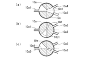
- Figure 5 is a schematic cross-sectional view of the five-way valve 10.
- Figure 5(a) is a cross-sectional view including the guide flow passage 10c1.
- the guide flow passage 10c1 has an upstream portion that can be connected to the first connection portion 10a1.
- the upstream portion of this guide flow passage 10c1 is formed in a sector shape that narrows from the circumferential surface of the upper core 10c toward the center.
- the upstream portion of the guide flow passage 10c1 is formed so that the circumferential flow passage width on the circumferential surface of the upper core 10c is approximately the same as the circumferential separation dimension between the third connection portion 10a3 and the fourth connection portion 10a4.
- the guide flow passage 10c1 has a downstream portion that can be connected to the fourth connection portion 10a4.
- the downstream portion of this guide flow passage 10c1 is formed in a sector shape that narrows from the circumferential surface of the upper core 10c toward the center.
- the downstream portion of the guide flow passage 10c1 is formed so that the circumferential flow passage width on the circumferential surface of the upper core 10c is approximately the same as the circumferential separation dimension between the third connection portion 10a3 and the fourth connection portion 10a4.
- the upstream portion of the guide flow passage 10c1 is connected to the first connection portion 10a1 and the downstream portion of the guide flow passage 10c1 is connected to the fourth connection portion 10a4, in the second connection mode described below, the upstream portion of the guide flow passage 10c1 is connected to the first connection portion 10a1 and the downstream portion of the guide flow passage 10c1 is connected to the fourth connection portion 10a4, and in the third and fourth connection modes described below, the guide flow passage 10c1 is formed so that the upstream and downstream portions of the guide flow passage 10c1 are blocked by the case 10a.
- the middle core 10d is located between the upper core 10c and the lower core 10e.
- the middle core 10d is provided with a guide passage 10d1.
- the guide passage 10d1 has an upstream portion that is provided on the top surface of the middle core 10d, a downstream portion that is provided on the bottom of the middle core 10d, and a connection portion that connects the upstream portion and the downstream portion is provided in the center of the middle core 10d.
- the middle core 10d is provided at a height where the upstream portion can be connected to the first connection portion 10a1 (i.e., the downstream end of the electrical equipment heat exchange passage 4), and the downstream portion can be connected to the third connection portion 10a3 (i.e., the upstream end of the electrical equipment heat exchange passage 4) and the fifth connection portion 10a5 (i.e., the upstream end of the battery heat exchange passage 6).
- Figure 5(b) is a cross-sectional view including the guide flow passage 10d1.
- the upstream portion of the guide flow passage 10d1 is formed in a sector shape that narrows from the circumferential surface of the middle core 10d toward the center.
- the upstream portion of the guide flow passage 10d1 is formed so that the circumferential flow passage width on the circumferential surface of the middle core 10d is the same as that of the guide flow passage 10c1.
- the downstream portion of the guide flow passage 10d1 is provided so as to extend from the center of the middle core 10d toward the circumferential surface with the same narrow flow passage width.
- the downstream portion of the guide flow passage 10d1 is formed so that the flow passage width is approximately the same as the flow passage width of the third connection portion 10a3 and the fifth connection portion 10a5.
- the upstream and downstream portions of the guide flow passage 10d1 are blocked by the case 10a in the first and second connection modes described below, the upstream portion of the guide flow passage 10d1 is connected to the first connection portion 10a1 and the downstream portion of the guide flow passage 10d1 is connected to the fifth connection portion 10a5 in the third connection mode described below, and the upstream portion of the guide flow passage 10d1 is connected to the first connection portion 10a1 and the downstream portion of the guide flow passage 10d1 is connected to the third connection portion 10a3 in the fourth connection mode described below.
- the lower core 10e is located at the bottom among the upper core 10c, the middle core 10d, and the lower core 10e.
- the lower core 10e has a guide passage 10e1 on its upper surface.
- the guide passage 10e1 is provided at a height that allows it to connect to the second connection portion 10a2 (i.e., the downstream end of the outside air heat exchange passage 5), the third connection portion 10a3 (i.e., the upstream end of the electrical equipment heat exchange passage 4), and the fifth connection portion 10a5 (i.e., the upstream end of the battery heat exchange passage 6).
- Figure 5(c) is a cross-sectional view including the guide flow passage 10e1.
- the upstream portion of the guide flow passage 10e1 is formed in a sector shape that narrows from the circumferential surface of the lower core 10e toward the center.
- the upstream portion of the guide flow passage 10e1 is formed so that the circumferential flow passage width on the circumferential surface of the lower core 10e is the same as that of the guide flow passage 10c1.
- the downstream portion of the guide flow passage 10e1 is provided so as to extend from the center of the lower core 10e toward the circumferential surface with the same narrow flow passage width.
- the downstream portion of the guide flow passage 10e1 is formed so that the flow passage width is approximately the same as the flow passage width of the third connection portion 10a3 and the fifth connection portion 10a5.
- the upstream portion of the guide flow passage 10e1 is connected to the second connection portion 10a2 and the downstream portion of the guide flow passage 10e1 is connected to the fifth connection portion 10a5, in the second connection mode described below, the upstream portion of the guide flow passage 10e1 is connected to the second connection portion 10a2 and the downstream portion of the guide flow passage 10e1 is connected to the third connection portion 10a3, and in the third and fourth connection modes described below, the guide flow passage 10e1 is formed so that the upstream and downstream portions of the guide flow passage 10e1 are blocked by the case 10a.
- connection state of the electrical equipment heat exchange passage 4, the outside air heat exchange passage 5, and the battery heat exchange passage 6 can be switched between a first connection mode, a second connection mode, a third connection mode, and a fourth connection mode.
- FIG. 5 is a schematic diagram for explaining the rotational position of the core 10b in the first connection mode.
- FIG. 6 is a schematic diagram showing the flow of the heat medium X for thermal management in the first connection mode.
- the downstream end of the electrical component heat exchange passage 4 i.e., the first connection portion 10a1
- the upstream end of the outside air heat exchange passage 5 i.e., the fourth connection portion 10a4
- the downstream end of the outside air heat exchange passage 5 i.e., the second connection portion 10a2
- the upstream end of the battery heat exchange passage 6 i.e., the fifth connection portion 10a5
- the heat management heat medium X sent from the pump 7 flows from the downstream end of the electrical equipment heat exchange passage 4 through the five-way valve 10 into the outside air heat exchange passage 5, flows from the downstream end of the outside air heat exchange passage 5 through the five-way valve 10 into the upstream end of the battery heat exchange passage 6, and is returned from the downstream end of the battery heat exchange passage 6 to the electrical equipment heat exchange passage 4.
- the heat management heat medium X is heat exchanged with the outside air heat exchanger 2, the internal heat exchanger 3, the on-board charger 103, the DC/DC converter 104, the battery 105, and the oil cooler 9b.
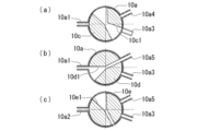
- FIG. 7 is a schematic diagram for explaining the rotational position of the core 10b in the second connection mode.
- FIG. 8 is a schematic diagram showing the flow of the heat medium X for thermal management in the second connection mode.
- the upstream end of the electrical component heat exchange passage 4 i.e., the third connection portion 10a3
- the downstream end of the electrical component heat exchange passage 4 i.e., the first connection portion 10a1
- the upstream end of the external air heat exchange passage 5 i.e., the fourth connection portion 10a4
- the downstream end of the external air heat exchange passage 5 i.e., the second connection portion 10a2
- the heat management heat medium X pumped out from the pump 7 flows from the downstream end of the electrical equipment heat exchange passage 4 through the five-way valve 10 into the outside air heat exchange passage 5, and flows from the downstream end of the outside air heat exchange passage 5 into the upstream end of the electrical equipment heat exchange passage 4 through the five-way valve 10.
- the heat management heat medium X is heat exchanged with the outside air heat exchanger 2, the internal heat exchanger 3, the on-board charger 103, the DC/DC converter 104, and the oil cooler 9b. Therefore, in the second connection mode, the driving motor 101, the inverter 102, the on-board charger 103, and the DC/DC converter 104 are thermally managed directly or indirectly by heat exchange with the heat management heat medium X.
- FIG. 9 is a schematic diagram for explaining the rotational position of the core 10b in the third connection mode.
- FIG. 10 is a schematic diagram showing the flow of the heat management heat medium X in the third connection mode.
- the downstream end of the electrical component heat exchange passage 4 i.e., the first connection part 10a1
- the upstream end of the battery heat exchange passage 6 i.e., the fifth connection part 10a5
- the heat management heat medium X sent from the pump 7 flows from the downstream end of the electrical equipment heat exchange flow path 4 through the five-way valve 10 into the upstream end of the battery heat exchange flow path 6, and is returned from the downstream end of the battery heat exchange flow path 6 to the electrical equipment heat exchange flow path 4.
- the heat management heat medium X is heat exchanged with the on-board charger 103, the DC/DC converter 104, the battery 105, and the oil cooler 9b.
- FIG. 11 is a schematic diagram for explaining the rotational position of the core 10b in the fourth connection mode.
- FIG. 12 is a schematic diagram showing the flow of the heat management heat medium X in the fourth connection mode.
- the upstream end of the electrical component heat exchange passage 4 i.e., the third connection portion 10a3
- the downstream end of the electrical component heat exchange passage 4 i.e., the first connection portion 10a1
- the five-way valve 10 As shown in these figures, in the fourth connection mode, the upstream end of the electrical component heat exchange passage 4 (i.e., the third connection portion 10a3) and the downstream end of the electrical component heat exchange passage 4 (i.e., the first connection portion 10a1) are connected by the five-way valve 10.
- the heat management heat medium X sent from the pump 7 flows from the downstream end of the electrical equipment heat exchange passage 4 through the five-way valve 10 into the upstream end of the electrical equipment heat exchange passage 4.
- the heat management heat medium X is heat exchanged with the on-board charger 103, the DC/DC converter 104, and the oil cooler 9b.
- the traction motor 101, the inverter 102, the on-board charger 103, and the DC/DC converter 104 are thermally managed directly or indirectly by heat exchange with the heat management heat medium X.
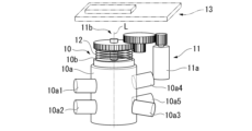
- FIG. 13 is a schematic perspective view including the drive unit 11, the biasing unit 12, and the rotation angle sensor 13.
- the drive unit 11 drives the five-way valve 10, and as shown in FIG. 13, includes a motor 11a and a gear group 11b. Under the control of the control unit 14, the motor 11a generates power for rotating the core 10b of the five-way valve 10.
- the gear group 11b transmits the power generated by the motor 11a to the core 10b.
- the biasing portion 12 biases the core 10b to a rotational position corresponding to the first connection mode.
- the biasing portion 12 is formed by a coil spring.
- the biasing portion 12 may be formed by another spring.
- the lower end of this biasing portion 12 is fixed to the upper surface of the core 10b, and the upper end is fixed to a support portion (not shown).
- the biasing portion 12 twists when the core 10b is rotated from the rotational position corresponding to the first connection mode, generating the biasing force.
- the biasing portion 12 returns the core 10b to the rotational position corresponding to the first connection mode.
- the biasing force generated by the biasing portion 12 is smaller than the power generated by the motor 11a. Therefore, the core 10b can be rotated by the power generated by the motor 11a.
- the rotation angle sensor 13 detects the rotational position of the core 10b and inputs the detection result to the control unit 14.
- the rotation angle sensor 13 is disposed, for example, above the core 10b.
- the control unit 14 controls the five-way valve 10 via the drive unit 11. By controlling the five-way valve 10, the control unit 14 switches the connection states of the electrical equipment heat exchange path 4, the outside air heat exchange path 5, and the battery heat exchange path 6 among a first connection mode, a second connection mode, a third connection mode, and a fourth connection mode.
- the control unit 14 may also control the pump 7 and the cooling oil pump 9c.
- the control unit 14 may also be an ECU (Electronic Control Unit) mounted on the vehicle 100. In such a case, the control unit 14 may control the inverter 102, etc.
- the vehicle 100 is equipped with an outside air temperature sensor, an interior temperature sensor, and a heat management heat medium temperature sensor, none of which are shown.
- the control unit 14 may be connected to these outside air temperature sensors and the heat management heat medium temperature sensor. In such a case, the control unit 14 receives a signal indicating the outside air temperature from the outside air temperature sensor, and a signal indicating the heat management heat medium temperature from the heat management heat medium temperature sensor.
- the control unit 14 may also receive a signal indicating the operating status of the interior air conditioning system 20.
- the control unit 14 may receive an equipment status signal indicating the status of equipment installed in the vehicle 100.
- the control unit 14 sets the connection state of the electrical component heat exchange path 4, the outside air heat exchange path 5, and the battery heat exchange path 6 to the first connection mode shown in FIG. 6. Furthermore, in such a case, when the outside air temperature is low, the control unit 14 may set the connection state of the electrical component heat exchange path 4, the outside air heat exchange path 5, and the battery heat exchange path 6 to the third connection mode shown in FIG. 10.
- the control unit 14 sets the connection state of the electrical equipment heat exchange path 4, the outside air heat exchange path 5, and the battery heat exchange path 6 to the second connection mode shown in FIG. 8. Also, when the vehicle 100 is running, the interior air conditioning system 20 is not operating, and the driving motor 101 needs to be warmed up, the control unit 14 sets the connection state of the electrical equipment heat exchange path 4, the outside air heat exchange path 5, and the battery heat exchange path 6 to, for example, the fourth connection mode shown in FIG. 12.
- the interior air conditioning system 20 when the vehicle 100 is running, the interior air conditioning system 20 is not operating, and the driving motor 101 and the battery 105 need to be warmed up, the connection state of the electrical equipment heat exchange path 4, the outside air heat exchange path 5, and the battery heat exchange path 6 to, for example, the third connection mode shown in FIG. 10, and the heater 8 heats the heat management heat medium X.
- control unit 14 sets the connection state of the electrical equipment heat exchange path 4, the outside air heat exchange path 5, and the battery heat exchange path 6 to the second connection mode shown in FIG. 8.
- control unit 14 sets the connection state of the electrical equipment heat exchange path 4, the outside air heat exchange path 5, and the battery heat exchange path 6 to the first connection mode shown in FIG. 6.
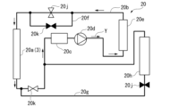
- FIG. 14 is a system configuration diagram showing the schematic configuration of an example of a vehicle interior air conditioning system 20.
- the vehicle interior air conditioning system 20 uses an air conditioning heat medium Y to generate conditioned air to be supplied to the vehicle interior.
- the vehicle air conditioning system 20 includes a condenser 20a, a first circulation flow path 20b, an accumulator 20c, a compressor 20d, an internal heating condenser 20e, an expansion valve bypass flow path 20f, a second circulation flow path 20g, an evaporator 20h, a plurality of expansion valves 20j, and a plurality of shutoff valves 20k.
- the condenser 20a is a heat exchanger that exchanges heat between the air-conditioning heat medium Y and the heat management heat medium X, and corresponds to the internal heat exchanger 3 of the heat management system 1. During heating, the condenser 20a functions as an evaporator that evaporates the air-conditioning heat medium Y. During cooling, the condenser 20a functions as a condenser that condenses the air-conditioning heat medium Y.
- the first circulation flow path 20b is a circulation flow path in which the condenser 20a is provided at an intermediate position.
- the first circulation flow path 20b guides the air-conditioning heat medium Y to circulate through the condenser 20a.
- the accumulator 20c is provided midway through the first circulation flow path 20b, and is disposed downstream of the condenser 20a and upstream of the internal heating condenser 20e in the flow direction of the air-conditioning heat medium Y.
- the accumulator 20c is a container that temporarily stores the air-conditioning heat medium Y flowing through the first circulation flow path 20b.
- the compressor 20d is provided midway through the first circulation flow path 20b, and is disposed downstream of the accumulator 20c and upstream of the internal heating condenser 20e in the flow direction of the air-conditioning heat medium Y.
- the compressor 20d compresses the air-conditioning heat medium Y and sends it downstream.
- the heating internal condenser 20e is a heat exchanger that uses the heat of the air-conditioning heat medium Y to heat the air to be supplied to the vehicle cabin.
- the heating internal condenser 20e is provided midway through the first circulation flow path 20b.
- the heating internal condenser 20e functions as a condenser that condenses the air-conditioning heat medium Y.
- the heating internal condenser 20e absorbs heat from the air-conditioning heat medium Y in a gaseous state as necessary.
- an expansion valve 20j is provided downstream of the heating internal condenser 20e and upstream of the condenser 20a.
- This expansion valve 20j cools the air-conditioning heat medium Y in a liquid state condensed in the heating internal condenser 20e by reducing the pressure.
- the expansion valve bypass flow path 20f is connected to the first circulation flow path 20b so as to bypass this expansion valve 20j.
- a shutoff valve 20k is provided midway along the expansion valve bypass flow path 20f.
- the shutoff valve 20k closes the expansion valve bypass flow path 20f during heating and opens the expansion valve bypass flow path 20f during cooling.
- the second circulation flow path 20g is an annular flow path whose upstream and downstream ends are connected to the first circulation flow path 20b.
- the upstream and downstream ends of the second circulation flow path 20g are connected to the first circulation flow path 20b downstream of the condenser 20a and upstream of the accumulator 20c.
- the upstream end of the second circulation flow path 20g is located upstream of the downstream end of the second circulation flow path 20g.
- the evaporator 20h is a heat exchanger that uses the latent heat of the air-conditioning heat medium Y to cool the air to be supplied to the vehicle interior.
- the evaporator 20h is provided in the middle of the second circulation flow path 20g.
- the evaporator 20h functions as an evaporator that evaporates the liquid air-conditioning heat medium Y during cooling.
- the expansion valve 20j lowers the temperature of the air-conditioning heat medium Y by suddenly lowering the pressure of the air-conditioning heat medium Y.
- one expansion valve 20j is disposed in the first circulation flow path 20b downstream of the heating internal condenser 20e and upstream of the condenser 20a.
- one expansion valve 20j is disposed in the second circulation flow path 20g upstream of the evaporator 20h.
- the expansion valve 20j is also capable of closing the flow path in which it is provided.
- Shut-off valve 20k is an on-off valve that opens and closes the provided flow path. As described above, one shut-off valve 20k is provided in expansion valve bypass flow path 20f. In addition, one shut-off valve 20k is provided midway through first circulation flow path 20b, between the upstream end of second circulation flow path 20g and the downstream end of second circulation flow path 20g.
- the expansion valve 20j provided in the second circulation flow path 20g closes the flow path.
- the shutoff valve 20k provided in the expansion valve bypass flow path 20f closes the flow path.
- the shutoff valve 20k and the expansion valve 20j provided in the first circulation flow path 20b open the flow paths.
- the air-conditioning heat medium Y that has passed through the condenser 20a is pressurized by the compressor 20d.
- the air-conditioning heat medium Y compressed by the compressor 20d is condensed in the internal heating condenser 20e, and then depressurized by the expansion valve 20j provided midway along the first circulation flow path 20b that runs from the internal heating condenser 20e to the condenser 20a.
- the expansion valve 20j provided in the second circulation flow path 20g opens the flow path.
- the shutoff valve 20k provided in the expansion valve bypass flow path 20f opens the flow path.
- the shutoff valve 20k and the expansion valve 20j provided in the first circulation flow path 20b close the flow paths.
- the air-conditioning heat medium Y that has passed through the condenser 20a is depressurized by the expansion valve 20j, and then absorbs heat from the air in the evaporator 20h.
- the air-conditioning heat medium Y that has passed through the evaporator 20h is pressurized by the compressor 20d.
- the air-conditioning heat medium Y compressed by the compressor 20d passes through the heating internal condenser 20e in a liquid state, and is then returned to the condenser 20a via the expansion valve bypass passage 20f.
- the thermal management system 1 of this embodiment as described above is mounted on a vehicle 100 and performs thermal management of a thermal management subject 110 including electrical equipment (on-board charger 103 and DC/DC converter 104).
- the thermal management system 1 of this embodiment includes an electrical equipment heat exchange path 4, an outside air heat exchange path 5, a battery heat exchange path 6, and a five-way valve 10.
- the electrical equipment heat exchange path 4 guides the thermal management heat medium X so that it passes through the electrical equipment.
- the outside air heat exchange path 5 guides the thermal management heat medium X so that it passes through the outside air heat exchanger 2 which performs heat exchange between the outside air and the thermal management heat medium X.
- the battery heat exchange path 6 guides the thermal management heat medium X so that it passes through the battery 105.
- the five-way valve 10 is disposed at the connection between the electrical equipment heat exchange passage 4, the outside air heat exchange passage 5, and the battery heat exchange passage 6, and can switch the direction of the heat management heat medium X to the electrical equipment heat exchange passage 4, the outside air heat exchange passage 5, and the battery heat exchange passage 6.
- the thermal management system 1 of this embodiment can change the connection state between the electrical equipment heat exchange path 4, the outside air heat exchange path 5, and the battery heat exchange path 6 by controlling the five-way valve 10 arranged at the connection portion between the electrical equipment heat exchange path 4, the outside air heat exchange path 5, and the battery heat exchange path 6. Therefore, the thermal management system 1 of this embodiment can change the flow path of the thermal management heat medium X without using multiple three-way valves and multiple opening and closing valves. Therefore, the thermal management system 1 of this embodiment can change the flow path through which the thermal management heat medium X is guided with a simple structure.
- the five-way valve 10 is connected to the upstream end of the electrical equipment heat exchange passage 4, the downstream end of the electrical equipment heat exchange passage 4, the upstream end of the outside air heat exchange passage 5, the downstream end of the outside air heat exchange passage 5, and the upstream end of the battery heat exchange passage 6. Furthermore, the downstream end of the battery heat exchange passage 6 is connected to a midpoint of the electrical equipment heat exchange passage 4.
- the five-way valve 10 can be used as a switching valve.
- the thermal management system 1 of this embodiment also includes a pump 7 that is provided midway through the electrical equipment heat exchange passage 4 and pumps the heat management heat medium X.
- the thermal management system 1 of this embodiment can use a single pump 7 to cause the heat management heat medium X to flow through the electrical equipment heat exchange passage 4, the outside air heat exchange passage 5, and the battery heat exchange passage 6. This allows the thermal management system 1 of this embodiment to have a simple structure.
- the thermal management system 1 of this embodiment also includes a drive unit 11 that drives the five-way valve 10.
- the five-way valve 10 also connects the electrical equipment heat exchange passage 4, the outside air heat exchange passage 5, and the battery heat exchange passage 6 so that the thermal management heat medium X is guided through all of the electrical equipment heat exchange passage 4, the outside air heat exchange passage 5, and the battery heat exchange passage 6 when no power is being transmitted from the drive unit 11.
- the thermal management heat medium X flows through all of the electrical equipment heat exchange path 4, the outside air heat exchange path 5, and the battery heat exchange path 6. Therefore, even when no power is transmitted from the drive unit 11, thermal management of the traction motor 101, the inverter 102, the on-board charger 103, the DC/DC converter 104, and the battery 105 can be performed.
- the five-way valve 10 includes a case 10a and a core 10b.
- the electrical equipment heat exchange passage 4, the outside air heat exchange passage 5, and the battery heat exchange passage 6 are fixed to the case 10a.
- the core 10b rotates inside the case 10a and determines the connection state between the electrical equipment heat exchange passage 4, the outside air heat exchange passage 5, and the battery heat exchange passage 6 depending on the rotational position.
- the thermal management system 1 of this embodiment further includes a biasing unit 12.
- the biasing unit 12 biases the core 10b to a rotational position where the thermal management heat medium X is guided through all of the electrical equipment heat exchange passage 4, the outside air heat exchange passage 5, and the battery heat exchange passage 6.
- the biasing force of the biasing unit 12 can move the core 10b to a rotational position where the heat management heat medium X is guided through all of the electrical equipment heat exchange path 4, the outside air heat exchange path 5, and the battery heat exchange path 6. Therefore, in the thermal management system 1 of this embodiment, when no power is transmitted from the drive unit 11, it is possible to more reliably flow the heat management heat medium X through all of the electrical equipment heat exchange path 4, the outside air heat exchange path 5, and the battery heat exchange path 6.
- an internal heat exchanger 3 that dissipates heat to the thermal management heat medium X with respect to other heat media contained in the vehicle 100 is provided in a midway position of the outside air heat exchange flow path 5.
- the thermal management system 1 of this embodiment it is possible to effectively utilize the heat recovered by the thermal management heat medium X in another system. Therefore, the thermal management system 1 of this embodiment can improve the electric power consumption of, for example, an electric vehicle.
- the internal heat exchanger 3 dissipates heat to the heat management heat medium X in contrast to the air conditioning heat medium Y used in the vehicle air conditioning system.
- the thermal management system 1 of this embodiment makes it possible to effectively utilize the heat recovered by the heat management heat medium X in the vehicle air conditioning system 20. Therefore, the thermal management system 1 of this embodiment makes it possible to improve the electric power consumption of, for example, an electric vehicle.
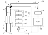
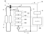
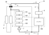
- FIG. 15 is a system configuration diagram showing the schematic configuration of the thermal management system 1A of this embodiment.
- the thermal management system 1A of this embodiment has a four-way valve 30 (switching valve) instead of the five-way valve 10 of the first embodiment.
- the thermal management system 1A of this embodiment does not have an oil cooling unit 9. For this reason, the traction motor 101 and the inverter 102 are disposed midway along the electrical equipment heat exchange flow path 4.
- the four-way valve 30 is a switching valve that is disposed at the connection point between the electrical equipment heat exchange passage 4, the outside air heat exchange passage 5, and the battery heat exchange passage 6. This four-way valve 30 can switch the destination of the thermal management heat medium X to the electrical equipment heat exchange passage 4, the outside air heat exchange passage 5, and the battery heat exchange passage 6. In this embodiment, the four-way valve 30 is connected to the upstream end of the electrical equipment heat exchange passage 4, the downstream end of the electrical equipment heat exchange passage 4, the downstream end of the outside air heat exchange passage 5, and the upstream end of the battery heat exchange passage 6.
- the upstream end of the outside air heat exchange passage 5 is connected to a midpoint of the electrical equipment heat exchange passage 4.
- the downstream end of the battery heat exchange passage 6 is connected to a midpoint of the electrical equipment heat exchange passage 4. Note that the drive unit 11, biasing unit 12, rotation angle sensor 13, and control unit 14 are omitted in FIG. 15.
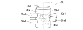
- FIG. 16 is a schematic perspective view of the four-way valve 30.
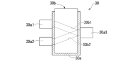
- FIG. 17 is a schematic vertical cross-sectional view of the four-way valve 30.
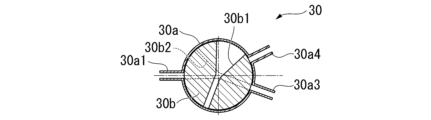
- the four-way valve 30 includes a case 30a and a core 30b.
- the case 30a is formed in a generally bottomed cylindrical shape with the axis L as the central axis, and rotatably houses the core 30b.
- the case 30a has a first connection portion 30a1, a second connection portion 30a2, a third connection portion 30a3, and a fourth connection portion 30a4 on the circumferential surface.
- the electrical equipment heat exchange passage 4, the outside air heat exchange passage 5, and the battery heat exchange passage 6 are each fixed to the case 30a.
- the first connection part 30a1 is connected to the downstream end of the outdoor air heat exchange passage 5.
- the first connection part 30a1 guides the heat management heat medium X supplied from the downstream end of the outdoor air heat exchange passage 5 into the inside of the case 30a.
- the second connection part 30a2 is connected to the downstream end of the electrical equipment heat exchange passage 4.
- the second connection part 30a2 guides the heat management heat medium X supplied from the downstream end of the electrical equipment heat exchange passage 4 into the inside of the case 30a.
- the third connection part 30a3 is connected to the upstream end of the electrical equipment heat exchange flow path 4.
- the third connection part 30a3 guides the heat management heat medium X inside the case 30a to flow into the electrical equipment heat exchange flow path 4.
- the fourth connection part 30a4 is connected to the upstream end of the battery heat exchange flow path 6.
- the fourth connection part 30a4 guides the heat management heat medium X inside the case 30a to flow into the battery heat exchange flow path 6.
- the first connection portion 30a1 is provided on the upper part of the case 30a.
- the second connection portion 30a2 is provided on the lower part of the case 30a. Furthermore, the first connection portion 30a1 and the second connection portion 30a2 are arranged so as to overlap when viewed from above.
- the third connection portion 30a3 and the fourth connection portion 30a4 are provided in the middle of the case 30a.
- the third connection portion 30a3 and the fourth connection portion 30a4 are disposed at the same height.
- the third connection portion 30a3 and the fourth connection portion 30a4 are disposed lower than the first connection portion 30a1 and higher than the second connection portion 30a2.
- the core 30b guides the heat management medium X inside the case 30a. Under the control of the control unit 14, the core 30b is rotated in the circumferential direction around the axis L by the drive unit 11. Depending on the position (rotational position) of the core 30b in the rotational direction around the axis L, the connection state between the electrical component heat exchange path 4, the outside air heat exchange path 5, and the battery heat exchange path 6 changes. In other words, the core 30b determines the connection state between the electrical component heat exchange path 4, the outside air heat exchange path 5, and the battery heat exchange path 6 depending on the rotational position.
- the core 30b has guide flow passages 30b1 and 30b2.
- the upstream portion of the guide flow passage 30b1 is formed at a height that allows it to be connected to the first connection portion 30a1, and the downstream portion is formed at a height that allows it to be connected to the third connection portion 30a3 and the fourth connection portion 30a4.
- the guide flow passage 30b1 is formed with an incline so as to continuously descend from the upstream portion to the downstream portion.
- the upstream portion of the guide flow passage 30b1 is formed in a sector shape that narrows from the circumferential surface of the core 30b toward the center.
- the upstream portion of the guide flow passage 30b1 is formed so that the circumferential flow passage width on the circumferential surface of the core 30b is approximately the same as the circumferential separation dimension between the third connection portion 30a3 and the fourth connection portion 30a4.
- the downstream portion of the guide flow passage 30b1 is provided so as to extend from the center of the core 30b toward the circumferential surface with the same narrow flow passage width.
- the downstream portion of the guide flow passage 30b1 is formed so that the flow passage width is approximately the same as the flow passage width of the third connection portion 30a3 and the fourth connection portion 30a4.
- the upstream portion of the guide flow passage 30b2 is formed at a height that allows it to be connected to the second connection portion 30a2, and the downstream portion is formed at a height that allows it to be connected to the third connection portion 30a3 and the fourth connection portion 30a4.
- the guide flow passage 30b2 is formed with an incline so that it rises continuously from the upstream portion to the downstream portion.
- the upstream portion of the guide flow passage 30b2 is formed in a sector shape that narrows from the circumferential surface of the core 30b toward the center.
- the upstream portion of the guide flow passage 30b2 is formed so that the circumferential flow passage width on the circumferential surface of the core 30b is approximately the same as the circumferential separation dimension between the third connection portion 30a3 and the fourth connection portion 30a4.
- the downstream portion of the guide flow passage 30b2 is provided so as to extend from the center of the core 30b toward the circumferential surface with the same narrow flow passage width.
- the downstream portion of the guide flow passage 30b2 is formed so that the flow passage width is approximately the same as the flow passage width of the third connection portion 30a3 and the fourth connection portion 30a4.
- the upstream portion of the guide flow passage 30b1 is connected to the first connection portion 30a1 and the downstream portion of the guide flow passage 30b1 is connected to the fourth connection portion 30a4, in a sixth connection mode described below, the upstream portion of the guide flow passage 30b1 is connected to the first connection portion 30a1 and the downstream portion of the guide flow passage 30b1 is connected to the third connection portion 30a3, and in a seventh and eighth connection modes described below, the upstream and downstream portions of the guide flow passage 30b1 are blocked by the case 30a.
- the core 30b is formed with the guide flow passage 30b2 such that in the fifth and sixth connection modes described below, the upstream and downstream portions of the guide flow passage 30b2 are blocked by the case 30a, in the seventh connection mode described below, the upstream portion of the guide flow passage 30b2 is connected to the second connection portion 30a2 and the downstream portion of the guide flow passage 30b2 is connected to the fourth connection portion 30a4, and in the eighth connection mode described below, the upstream portion of the guide flow passage 30b2 is connected to the second connection portion 30a2 and the downstream portion of the guide flow passage 30b2 is connected to the third connection portion 30a3.
- connection state of the electrical equipment heat exchange passage 4, the outside air heat exchange passage 5, and the battery heat exchange passage 6 can be switched to the fifth connection mode, sixth connection mode, seventh connection mode, and eighth connection mode.
- FIG. 18 is a schematic diagram for explaining the rotational position of the core 30b in the fifth connection mode.
- FIG. 19 is a schematic diagram showing the flow of the heat management heat medium X in the fifth connection mode.
- the downstream end of the outside air heat exchange passage 5 i.e., the first connection part 30a1
- the upstream end of the battery heat exchange passage 6 i.e., the fourth connection part 30a4
- the four-way valve 30 As shown in these figures, in the fifth connection mode, the downstream end of the outside air heat exchange passage 5 (i.e., the first connection part 30a1) and the upstream end of the battery heat exchange passage 6 (i.e., the fourth connection part 30a4) are connected by the four-way valve 30.
- the heat management heat medium X sent from the pump 7 flows from the electrical equipment heat exchange passage 4 to the upstream end of the outside air heat exchange passage 5, flows from the downstream end of the outside air heat exchange passage 5 through the four-way valve 30 to the upstream end of the battery heat exchange passage 6, and is returned from the downstream end of the battery heat exchange passage 6 to the electrical equipment heat exchange passage 4.
- the heat management heat medium X is heat exchanged with the outside air heat exchanger 2, the internal heat exchanger 3, the driving motor 101, the inverter 102, the on-board charger 103, the DC/DC converter 104, and the battery 105.
- the biasing unit 12 biases the core 30b to a rotational position corresponding to the fifth connection mode. Therefore, when no power is transmitted from the drive unit 11 to the core 30b, the biasing force of the biasing unit 12 can move the core 30b to a rotational position where the heat management medium X is guided through all of the electrical component heat exchange passage 4, the outside air heat exchange passage 5, and the battery heat exchange passage 6.
- FIG. 20 is a schematic diagram for explaining the rotational position of the core 30b in the sixth connection mode.
- FIG. 21 is a schematic diagram showing the flow of the heat management heat medium X in the sixth connection mode.
- the downstream end of the outside air heat exchange passage 5 i.e., the first connection portion 30a1
- the upstream end of the electrical component heat exchange passage 4 i.e., the third connection portion 30a3
- the four-way valve 30 As shown in these figures, in the sixth connection mode, the downstream end of the outside air heat exchange passage 5 (i.e., the first connection portion 30a1) and the upstream end of the electrical component heat exchange passage 4 (i.e., the third connection portion 30a3) are connected by the four-way valve 30.
- the heat management heat medium X pumped out from the pump 7 flows from the electrical equipment heat exchange passage 4 into the upstream end of the outside air heat exchange passage 5, and flows from the downstream end of the outside air heat exchange passage 5 through the four-way valve 30 into the upstream end of the electrical equipment heat exchange passage 4.
- the heat management heat medium X is heat exchanged with the outside air heat exchanger 2, the internal heat exchanger 3, the driving motor 101, the inverter 102, the on-board charger 103, and the DC/DC converter 104. Therefore, in the sixth connection mode, the driving motor 101, the inverter 102, the on-board charger 103, and the DC/DC converter 104 are thermally managed by heat exchange with the heat management heat medium X.
- FIG. 22 is a schematic diagram for explaining the rotational position of the core 30b in the seventh connection mode.
- FIG. 23 is a schematic diagram showing the flow of the heat management heat medium X in the seventh connection mode.
- the downstream end of the electrical component heat exchange passage 4 i.e., the second connection part 30a2
- the upstream end of the battery heat exchange passage 6 i.e., the fourth connection part 30a4
- the four-way valve 30 As shown in these figures, in the seventh connection mode, the downstream end of the electrical component heat exchange passage 4 (i.e., the second connection part 30a2) and the upstream end of the battery heat exchange passage 6 (i.e., the fourth connection part 30a4) are connected by the four-way valve 30.
- the heat management heat medium X sent from the pump 7 flows from the downstream end of the electrical equipment heat exchange passage 4 through the four-way valve 30 into the upstream end of the battery heat exchange passage 6, and is returned from the downstream end of the battery heat exchange passage 6 to the electrical equipment heat exchange passage 4.
- the heat management heat medium X is heat exchanged with the driving motor 101, the inverter 102, the on-board charger 103, the DC/DC converter 104, and the battery 105. Therefore, in the seventh connection mode, all of the driving motor 101, the inverter 102, the on-board charger 103, the DC/DC converter 104, and the battery 105 included in the thermal management subject 110 are thermally managed by heat exchange with the heat management heat medium X.
- FIG. 24 is a schematic diagram for explaining the rotational position of the core 30b in the eighth connection mode.
- FIG. 25 is a schematic diagram showing the flow of the heat management heat medium X in the eighth connection mode.
- the downstream end of the electrical component heat exchange passage 4 i.e., the second connection portion 30a2
- the upstream end of the electrical component heat exchange passage 4 i.e., the third connection portion 30a3
- the four-way valve 30 As shown in these figures, in the eighth connection mode, the downstream end of the electrical component heat exchange passage 4 (i.e., the second connection portion 30a2) and the upstream end of the electrical component heat exchange passage 4 (i.e., the third connection portion 30a3) are connected by the four-way valve 30.
- the heat management heat medium X pumped out from the pump 7 flows from the downstream end of the electrical equipment heat exchange passage 4 to the upstream end of the electrical equipment heat exchange passage 4 via the four-way valve 30.
- the heat management heat medium X is heat exchanged with the driving motor 101, the inverter 102, the on-board charger 103, and the DC/DC converter 104. Therefore, in the eighth connection mode, the driving motor 101, the inverter 102, the on-board charger 103, and the DC/DC converter 104 included in the thermal management subject 110 are thermally managed by heat exchange with the heat management heat medium X.
- the thermal management system 1A of this embodiment can change the connection state between the electrical equipment heat exchange path 4, the outside air heat exchange path 5, and the battery heat exchange path 6 by controlling the four-way valve 30, which is arranged at the connection portion between the electrical equipment heat exchange path 4, the outside air heat exchange path 5, and the battery heat exchange path 6. Therefore, the thermal management system 1A of this embodiment can change the flow path of the thermal management heat medium X without using multiple three-way valves and multiple opening and closing valves. Therefore, the thermal management system 1A of this embodiment can change the flow path through which the thermal management heat medium X is guided with a simple structure.
- the switching valve is a four-way valve 30 that connects the upstream end of the electrical equipment heat exchange path 4, the downstream end of the electrical equipment heat exchange path 4, the downstream end of the outside air heat exchange path 5, and the upstream end of the battery heat exchange path 6.
- the upstream end of the outside air heat exchange path 5 is connected to a midpoint of the electrical equipment heat exchange path 4.
- the downstream end of the battery heat exchange path 6 is connected to a midpoint of the electrical equipment heat exchange path 4.
- the four-way valve 30 can be used as the switching valve.
- FIG. 26 is a system configuration diagram showing the schematic configuration of a modified example of the thermal management system 1.
- a six-way valve 60 is provided instead of the five-way valve 10 and the downstream end of the battery heat exchange flow path 6 is connected to the six-way valve 60.
- the drive unit 11, the biasing unit 12, the rotation angle sensor 13, and the control unit 14 are omitted.
- a thermal management system that is mounted on a vehicle and performs thermal management of objects to be thermally managed, including electrical equipment, comprising: an electrical equipment heat exchange flow path for guiding a heat transfer medium for thermal management so as to pass through the electrical equipment; an outside air heat exchange flow path that guides the heat management medium to pass through an outside air heat exchanger that performs heat exchange between outside air and the heat management medium; a battery heat exchange flow path for guiding the thermal management heat medium through the battery; a switching valve that is arranged at a connection portion between the electrical equipment heat exchange path, the outside air heat exchange path, and the battery heat exchange path, and that is capable of switching the guide destination of the thermal management heat medium to the electrical equipment heat exchange path, the outside air heat exchange path, and the battery heat exchange path.
- the switching valve is a five-way valve to which an upstream end of the electrical equipment heat exchange passage, a downstream end of the electrical equipment heat exchange passage, an upstream end of the outside air heat exchange passage, a downstream end of the outside air heat exchange passage, and an upstream end of the battery heat exchange passage are connected; 2.
- the switching valve is a four-way valve in which an upstream end of the electrical equipment heat exchange passage, a downstream end of the electrical equipment heat exchange passage, a downstream end of the outside air heat exchange passage, and an upstream end of the battery heat exchange passage are connected to each other;
- the upstream end of the outside air heat exchange passage is connected to a middle portion of the electrical equipment heat exchange passage, 2.
- a drive unit that drives the switching valve is provided,
- the switching valve is a case in which the electrical equipment heat exchange passage, the outside air heat exchange passage, and the battery heat exchange passage are fixed; a core that is rotated inside the case and that determines a connection state between the electrical equipment heat exchange passage, the outside air heat exchange passage, and the battery heat exchange passage according to a rotation position,
- Appendix 7 A thermal management system as described in any one of appendices 1 to 6, characterized in that an internal heat exchanger that dissipates heat to the thermal management heat medium with respect to another heat medium contained in the vehicle, which is a vehicle internal heat medium, is provided at a midpoint in the outside air heat exchange flow path.
Landscapes
- Engineering & Computer Science (AREA)
- Mechanical Engineering (AREA)
- Transportation (AREA)
- Power Engineering (AREA)
- Life Sciences & Earth Sciences (AREA)
- Sustainable Development (AREA)
- Sustainable Energy (AREA)
- Chemical & Material Sciences (AREA)
- Combustion & Propulsion (AREA)
- Physics & Mathematics (AREA)
- Thermal Sciences (AREA)
- Air-Conditioning For Vehicles (AREA)
Abstract
Description
図1は、本実施形態の熱管理システム1が搭載される車両100の概略構成図である。車両100は、例えば電気自動車である。また、車両100は、内燃機関と走行用モータとが併設された所謂ハイブリッド自動車であってもよい。図1に示すように、車両100は、熱管理システム1の他、走行用モータ101、インバータ102、車載充電器103(電装品)、DC/DCコンバータ104(電装品)、バッテリ105を備える。また、車両100は、図1に示すように、車内空調システム20を備えている。
次に、図15~図25を参照して、本発明の第2実施形態について説明する。なお、本実施形態の説明において、上記第1実施形態と同様の部分については、その説明を省略あるいは簡略化する。
車両に搭載されて、電装品を含む熱管理対象の熱管理を行う熱管理システムであって、
前記電装品を通過するように熱管理用熱媒を案内する電装品熱交換流路と、
外気と前記熱管理用熱媒との熱交換を行う外気熱交換器を通過するように前記熱管理用熱媒を案内する外気熱交換流路と、
バッテリを通過するように前記熱管理用熱媒を案内するバッテリ熱交換流路と、
前記電装品熱交換流路と前記外気熱交換流路と前記バッテリ熱交換流路との接続部位に配置されると共に、前記電装品熱交換流路と前記外気熱交換流路と前記バッテリ熱交換流路とへの前記熱管理用熱媒の案内先を切換可能な切換弁と
を備えることを特徴とする熱管理システム。
前記切換弁は、前記電装品熱交換流路の上流端と、前記電装品熱交換流路の下流端と、前記外気熱交換流路の上流端と、前記外気熱交換流路の下流端と、前記バッテリ熱交換流路の上流端とが接続された五方弁であり、
前記バッテリ熱交換流路の下流端が前記電装品熱交換流路の途中部位に接続されている
ことを特徴とする付記1記載の熱管理システム。
前記切換弁は、前記電装品熱交換流路の上流端と、前記電装品熱交換流路の下流端と、前記外気熱交換流路の下流端と、前記バッテリ熱交換流路の上流端とが接続された四方弁であり、
前記外気熱交換流路の上流端が前記電装品熱交換流路の途中部位に接続され、
前記バッテリ熱交換流路の下流端が前記電装品熱交換流路の途中部位に接続されている
ことを特徴とする付記1記載の熱管理システム。
前記電装品熱交換流路の途中部位に設けられると共に前記熱管理用熱媒を圧送するポンプを備えることを特徴とする付記1~3のいずれか一つに記載の熱管理システム。
前記切換弁を駆動する駆動部を備え、
前記切換弁は、前記駆動部から動力が伝達されていない状態で、前記電装品熱交換流路と前記外気熱交換流路と前記バッテリ熱交換流路との全てにて前記熱管理用熱媒が案内されるように、前記電装品熱交換流路と前記外気熱交換流路と前記バッテリ熱交換流路とを接続する
ことを特徴とする付記1~4のいずれか一つに記載の熱管理システム。
前記切換弁は、
前記電装品熱交換流路と前記外気熱交換流路と前記バッテリ熱交換流路とが固定されるケースと、
前記ケース内部で回動されると共に回転位置に応じて前記電装品熱交換流路と前記外気熱交換流路と前記バッテリ熱交換流路との接続状態を規定する中子と
を備え、
前記電装品熱交換流路と前記外気熱交換流路と前記バッテリ熱交換流路との全てにて前記熱管理用熱媒が案内される前記回転位置に前記中子を付勢する付勢部をさらに備える
ことを特徴とする付記5記載の熱管理システム。
前記車両に含まれる他の熱媒である車両内部熱媒に対して前記熱管理用熱媒に放熱させる内部熱交換器が前記外気熱交換流路の途中部位に設けられていることを特徴とする付記1~6のいずれか一つに記載の熱管理システム。
前記内部熱交換器は、車内空調システムで用いられる前記車両内部熱媒に対して前記熱管理用熱媒に放熱させることを特徴とする付記7記載の熱管理システム。
1A 熱管理システム
2 外気熱交換器
3 内部熱交換器
4 電装品熱交換流路
5 外気熱交換流路
6 バッテリ熱交換流路
7 ポンプ
8 ヒータ
9 油冷ユニット
10 五方弁(切換弁)
10a ケース
10a1 第1接続部
10a2 第2接続部
10a3 第3接続部
10a4 第4接続部
10a5 第5接続部
10b 中子
10c 上部中子
10c1 案内流路
10d 中部中子
10d1 案内流路
10e 下部中子
10e1 案内流路
11 駆動部
11a モータ
11b ギア群
12 付勢部
13 回転角度センサ
14 制御部
30 四方弁(切換弁)
30a ケース
30a1 第1接続部
30a2 第2接続部
30a3 第3接続部
30a4 第4接続部
30b 中子
30b1 案内流路
30b2 案内流路
60 六方弁(切換弁)
61 ポンプ
100 車両
101 走行用モータ
102 インバータ
103 車載充電器
104 DC/DCコンバータ
105 バッテリ
110 熱管理対象
L 軸芯
X 熱管理用熱媒
Y 空調用熱媒
Z 冷却油
Claims (8)
- 車両に搭載されて、電装品を含む熱管理対象の熱管理を行う熱管理システムであって、
前記電装品を通過するように熱管理用熱媒を案内する電装品熱交換流路と、
外気と前記熱管理用熱媒との熱交換を行う外気熱交換器を通過するように前記熱管理用熱媒を案内する外気熱交換流路と、
バッテリを通過するように前記熱管理用熱媒を案内するバッテリ熱交換流路と、
前記電装品熱交換流路と前記外気熱交換流路と前記バッテリ熱交換流路との接続部位に配置されると共に、前記電装品熱交換流路と前記外気熱交換流路と前記バッテリ熱交換流路とへの前記熱管理用熱媒の案内先を切換可能な切換弁と
を備えることを特徴とする熱管理システム。 - 前記切換弁は、前記電装品熱交換流路の上流端と、前記電装品熱交換流路の下流端と、前記外気熱交換流路の上流端と、前記外気熱交換流路の下流端と、前記バッテリ熱交換流路の上流端とが接続された五方弁であり、
前記バッテリ熱交換流路の下流端が前記電装品熱交換流路の途中部位に接続されている
ことを特徴とする請求項1記載の熱管理システム。 - 前記切換弁は、前記電装品熱交換流路の上流端と、前記電装品熱交換流路の下流端と、前記外気熱交換流路の下流端と、前記バッテリ熱交換流路の上流端とが接続された四方弁であり、
前記外気熱交換流路の上流端が前記電装品熱交換流路の途中部位に接続され、
前記バッテリ熱交換流路の下流端が前記電装品熱交換流路の途中部位に接続されている
ことを特徴とする請求項1記載の熱管理システム。 - 前記電装品熱交換流路の途中部位に設けられると共に前記熱管理用熱媒を圧送するポンプを備えることを特徴とする請求項1~3のいずれか一項に記載の熱管理システム。
- 前記切換弁を駆動する駆動部を備え、
前記切換弁は、前記駆動部から動力が伝達されていない状態で、前記電装品熱交換流路と前記外気熱交換流路と前記バッテリ熱交換流路との全てにて前記熱管理用熱媒が案内されるように、前記電装品熱交換流路と前記外気熱交換流路と前記バッテリ熱交換流路とを接続する
ことを特徴とする請求項1~3のいずれか一項に記載の熱管理システム。 - 前記切換弁は、
前記電装品熱交換流路と前記外気熱交換流路と前記バッテリ熱交換流路とが固定されるケースと、
前記ケース内部で回動されると共に回転位置に応じて前記電装品熱交換流路と前記外気熱交換流路と前記バッテリ熱交換流路との接続状態を規定する中子と
を備え、
前記電装品熱交換流路と前記外気熱交換流路と前記バッテリ熱交換流路との全てにて前記熱管理用熱媒が案内される前記回転位置に前記中子を付勢する付勢部をさらに備える
ことを特徴とする請求項5記載の熱管理システム。 - 前記車両に含まれる他の熱媒である車両内部熱媒に対して前記熱管理用熱媒に放熱させる内部熱交換器が前記外気熱交換流路の途中部位に設けられていることを特徴とする請求項1~3のいずれか一項に記載の熱管理システム。
- 前記内部熱交換器は、車内空調システムで用いられる前記車両内部熱媒に対して前記熱管理用熱媒に放熱させることを特徴とする請求項7記載の熱管理システム。
Priority Applications (4)
| Application Number | Priority Date | Filing Date | Title |
|---|---|---|---|
| CN202380099297.9A CN121487847A (zh) | 2023-07-14 | 2023-07-14 | 热管理系统 |
| DE112023006683.3T DE112023006683T5 (de) | 2023-07-14 | 2023-07-14 | Wärmemanagementsystem |
| JP2025533737A JPWO2025017797A1 (ja) | 2023-07-14 | 2023-07-14 | |
| PCT/JP2023/026118 WO2025017797A1 (ja) | 2023-07-14 | 2023-07-14 | 熱管理システム |
Applications Claiming Priority (1)
| Application Number | Priority Date | Filing Date | Title |
|---|---|---|---|
| PCT/JP2023/026118 WO2025017797A1 (ja) | 2023-07-14 | 2023-07-14 | 熱管理システム |
Publications (1)
| Publication Number | Publication Date |
|---|---|
| WO2025017797A1 true WO2025017797A1 (ja) | 2025-01-23 |
Family
ID=94281702
Family Applications (1)
| Application Number | Title | Priority Date | Filing Date |
|---|---|---|---|
| PCT/JP2023/026118 Ceased WO2025017797A1 (ja) | 2023-07-14 | 2023-07-14 | 熱管理システム |
Country Status (4)
| Country | Link |
|---|---|
| JP (1) | JPWO2025017797A1 (ja) |
| CN (1) | CN121487847A (ja) |
| DE (1) | DE112023006683T5 (ja) |
| WO (1) | WO2025017797A1 (ja) |
Citations (5)
| Publication number | Priority date | Publication date | Assignee | Title |
|---|---|---|---|---|
| JP2014043181A (ja) * | 2012-08-28 | 2014-03-13 | Denso Corp | 車両用熱管理システム |
| JP2017082669A (ja) * | 2015-10-27 | 2017-05-18 | 株式会社山田製作所 | 冷却水流動及び潤滑油流動制御システム、並びに冷却水流動及び潤滑油流動制御方法 |
| JP2018204939A (ja) * | 2017-06-06 | 2018-12-27 | 株式会社デンソー | 熱交換装置 |
| JP2021042809A (ja) * | 2019-09-10 | 2021-03-18 | 株式会社デンソー | バルブ装置、流体循環回路 |
| JP2022096182A (ja) * | 2020-12-17 | 2022-06-29 | トヨタ自動車株式会社 | 車両 |
Family Cites Families (1)
| Publication number | Priority date | Publication date | Assignee | Title |
|---|---|---|---|---|
| JP7404936B2 (ja) | 2020-03-03 | 2023-12-26 | 株式会社デンソー | 熱管理システム |
-
2023
- 2023-07-14 WO PCT/JP2023/026118 patent/WO2025017797A1/ja not_active Ceased
- 2023-07-14 CN CN202380099297.9A patent/CN121487847A/zh active Pending
- 2023-07-14 JP JP2025533737A patent/JPWO2025017797A1/ja active Pending
- 2023-07-14 DE DE112023006683.3T patent/DE112023006683T5/de active Pending
Patent Citations (5)
| Publication number | Priority date | Publication date | Assignee | Title |
|---|---|---|---|---|
| JP2014043181A (ja) * | 2012-08-28 | 2014-03-13 | Denso Corp | 車両用熱管理システム |
| JP2017082669A (ja) * | 2015-10-27 | 2017-05-18 | 株式会社山田製作所 | 冷却水流動及び潤滑油流動制御システム、並びに冷却水流動及び潤滑油流動制御方法 |
| JP2018204939A (ja) * | 2017-06-06 | 2018-12-27 | 株式会社デンソー | 熱交換装置 |
| JP2021042809A (ja) * | 2019-09-10 | 2021-03-18 | 株式会社デンソー | バルブ装置、流体循環回路 |
| JP2022096182A (ja) * | 2020-12-17 | 2022-06-29 | トヨタ自動車株式会社 | 車両 |
Also Published As
| Publication number | Publication date |
|---|---|
| DE112023006683T5 (de) | 2026-06-25 |
| CN121487847A (zh) | 2026-02-06 |
| JPWO2025017797A1 (ja) | 2025-01-23 |
Similar Documents
| Publication | Publication Date | Title |
|---|---|---|
| US11919360B2 (en) | Vehicle heat management system | |
| JP7202124B2 (ja) | 車両の熱管理システム | |
| US11897309B2 (en) | Vehicle heat management system | |
| JP5433387B2 (ja) | 車両用機器冷却暖房システム | |
| JP5983187B2 (ja) | 車両用熱管理システム | |
| JP5949522B2 (ja) | 温調装置 | |
| CA2736341C (en) | Thermal management system with dual mode coolant loops | |
| JP6151760B2 (ja) | ハイブリッド自動車用空調回路、およびハイブリッド自動車の自動車電池を予熱するための方法 | |
| US20120222441A1 (en) | Heat Cycle System for Mobile Object | |
| CN103946042A (zh) | 冷却装置 | |
| CN102848876A (zh) | 车辆车厢和驱动系的热力调节装置 | |
| JP2013060190A (ja) | 車両の複数の構成要素を調温するための装置および車両システム | |
| JP2013220712A (ja) | 車載機器温調装置 | |
| JP2019051872A (ja) | 車両の熱交換システム | |
| CN117774592A (zh) | 车辆热管理系统及其控制方法 | |
| WO2022107429A1 (ja) | 温調装置 | |
| JP2013020497A (ja) | 組電池の温度調節装置 | |
| KR102869255B1 (ko) | 전기자동차의 냉각시스템용 더블 4-웨이 밸브 | |
| KR20250068389A (ko) | 차량 열관리시스템 | |
| WO2022107428A1 (ja) | 温調装置 | |
| US20240317015A1 (en) | Heat cycle system, in-wheel motor, and vehicle | |
| CN121487847A (zh) | 热管理系统 | |
| KR102909362B1 (ko) | 통합제어밸브 및 이의 작동방법 | |
| WO2022107381A1 (ja) | 温調装置 | |
| WO2025017812A1 (ja) | 熱管理システム |
Legal Events
| Date | Code | Title | Description |
|---|---|---|---|
| 121 | Ep: the epo has been informed by wipo that ep was designated in this application |
Ref document number: 23945802 Country of ref document: EP Kind code of ref document: A1 |
|
| ENP | Entry into the national phase |
Ref document number: 2025533737 Country of ref document: JP Kind code of ref document: A |
|
| WWE | Wipo information: entry into national phase |
Ref document number: 112023006683 Country of ref document: DE |
|
| WWP | Wipo information: published in national office |
Ref document number: 112023006683 Country of ref document: DE |
|
| 122 | Ep: pct application non-entry in european phase |
Ref document number: 23945802 Country of ref document: EP Kind code of ref document: A1 |