WO2025017779A1 - リビングヒンジの構造 - Google Patents
リビングヒンジの構造 Download PDFInfo
- Publication number
- WO2025017779A1 WO2025017779A1 PCT/JP2023/026066 JP2023026066W WO2025017779A1 WO 2025017779 A1 WO2025017779 A1 WO 2025017779A1 JP 2023026066 W JP2023026066 W JP 2023026066W WO 2025017779 A1 WO2025017779 A1 WO 2025017779A1
- Authority
- WO
- WIPO (PCT)
- Prior art keywords
- hinge
- living
- living hinge
- curvature
- hinge portion
- Prior art date
- Legal status (The legal status is an assumption and is not a legal conclusion. Google has not performed a legal analysis and makes no representation as to the accuracy of the status listed.)
- Pending
Links
Images


Classifications
-
- F—MECHANICAL ENGINEERING; LIGHTING; HEATING; WEAPONS; BLASTING
- F16—ENGINEERING ELEMENTS AND UNITS; GENERAL MEASURES FOR PRODUCING AND MAINTAINING EFFECTIVE FUNCTIONING OF MACHINES OR INSTALLATIONS; THERMAL INSULATION IN GENERAL
- F16C—SHAFTS; FLEXIBLE SHAFTS; ELEMENTS OR CRANKSHAFT MECHANISMS; ROTARY BODIES OTHER THAN GEARING ELEMENTS; BEARINGS
- F16C11/00—Pivots; Pivotal connections
- F16C11/04—Pivotal connections
- F16C11/12—Pivotal connections incorporating flexible connections, e.g. leaf springs
Definitions
- This disclosure relates to the structure of a living hinge.
- a living hinge is a structure that connects two parts with a thin part, allowing the parts to be opened and closed.
- a living hinge is made by injecting molten resin into the gap in a mold to mold the container and lid into a single shape that can be folded.
- Living hinges generally use polymer materials that are relatively flexible (large elongation at break) such as polypropylene or polyethylene.
- a properly designed living hinge is expected to withstand unlimited folding cycles (Non-Patent Document 1).
- Non-Patent Document 2 Non-Patent Document 2
- Non-Patent Document 3 When stress is applied to polymeric materials such as polypropylene and polyethylene, they generally pass through the elastic deformation region, then cracks appear in the region beyond the yield point (plastic deformation region), and if the load increases further, they break (Non-Patent Document 3).
- This disclosure has been made in light of the above, and aims to improve the durability of living hinges.
- the structure of a living hinge includes a first member, a second member, a hinge portion that connects the first member and the second member, and a guide portion that limits the radius of curvature of the hinge portion within a predetermined range when the hinge portion is bent.
- This disclosure makes it possible to improve the durability of living hinges.
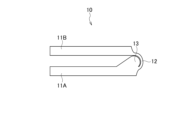
- FIG. 1 is a side view of a living hinge in a normal state.
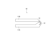
- FIG. 2 is a side view of the living hinge when folded.
- FIG. 3 is a side view of the living hinge when folded.
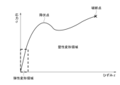
- FIG. 4 is a diagram showing an example of a stress-strain curve of a polymer material.
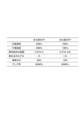
- FIG. 5 is a diagram showing an example of physical property values of a polymer material before and after degradation.
- FIG. 6 is an image of the hinge portion when folded.
- FIG. 7 is a diagram showing an example of a state of the hinge portion when folded.
- FIG. 8 is a diagram showing an example of the size of the living hinge of the embodiment when folded.
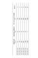
- FIG. 9 is a diagram showing an example of an experimental result of the living hinge of the embodiment.
- FIG. 1 is a side view of the living hinge 10 in a normal state
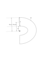
- Figure 2 is a side view of the living hinge 10 in a bent state.
- the living hinge 10 has a structure in which a first member 11A and a second member 11B are connected by a thin plate-like hinge portion 12.
- the living hinge 10 can be bent along the hinge portion 12.
- the living hinge 10 has a guide portion 13 that comes into contact with the hinge portion 12 when bent.
- first member 11A and the second member 11B are plate-shaped members, but this is not limited to this.
- first member 11A or the second member 11B may be a container and the other a lid.
- the hinge portion 12 is a thin plate-like member disposed between the first member 11A and the second member 11B, and connects the first member 11A and the second member 11B.
- the hinge portion 12 is bendable.
- the hinge portion 12 has a thickness of 1 mm and a width of 1-3 cm, for example, but is not limited to this.
- the hinge portion 12 only needs to be wide enough to be bendable within the desired range.
- the guide portion 13 is a protrusion that restricts the hinge portion 12 from bending excessively.
- the hinge portion 12 comes into contact with the guide portion 13, so that the degree of bending (radius of curvature) of the hinge portion 12 can be restricted within a predetermined range. This makes it possible to reduce the stress applied to the hinge portion 12.
- the guide portion 13 may be provided on both sides of the first member 11A.
- the guide portion 13 may be provided on both the first member 11A and the second member 11B.
- the cross-sectional shape of the guide portion 13 is such that the contact point with the hinge portion 12 is an arc having a radius of curvature when the hinge portion 12 is bent.
- the contact point with the hinge portion 12 may not be a curved surface, and the hinge portion 12 and the guide portion 13 may contact at several points.
- the shape of the guide portion 13 may be such that it can limit the degree of bending of the hinge portion 12 within a predetermined range.
- the hinge portion 12 and the guide portion 13 may not come into contact with each other, and the degree of bending of the hinge portion 12 may be limited to a predetermined range.
- the living hinge 10 is made by integrally molding the first member 11A, the second member 11B, the hinge portion 12, and the guide portion 13.
- the polymer material used for the living hinge 10 has enough flexibility to be bent.
- polyethylene and polypropylene can be used as the polymer material.
- Figure 4 is an example of a stress-strain curve for a polymer material.
- stress is applied to polymer materials such as polypropylene and polyethylene, after passing through the elastic deformation region, cracks appear in the region beyond the yield point (plastic deformation region), and if the load increases further, the material will break.
- Such a curve can be drawn by conducting a tensile test using a dumbbell-shaped test piece (JIS K7161-1, ISO527-1). Note that the stress-strain curve can take various forms depending on the type of polymer material, so it will not necessarily follow the shape of the graph in Figure 4.
- the yield point of the polymer material used in the living hinge 10 is measured in advance.
- a radius of curvature is calculated so that the strain of the hinge portion 12 when bent is less than 100% of the strain at the yield point, more preferably within 80%, and the guide portion 13 is designed so that the hinge portion 12 bends at a value larger than that radius of curvature. This makes it possible to suppress the occurrence of cracks in the living hinge.
- the strain of the hinge portion 12 is the extension of the outer length of the hinge portion 12 when folded, and the radius of curvature is the radius of curvature of the inner side of the hinge portion 12 when folded.
- the outer and inner sides of the hinge portion 12 are the outer and inner sides when viewed from the side when the hinge portion 12 is folded.
- FIG. 5 shows an example of the physical properties of a polymeric material before and after degradation.
- Figure 5 shows the compressive strength, tensile strength, range of elastic deformation, strain at yield point, elongation at break, and Young's modulus for polypropylene before and after degradation.
- the stress-strain curve in Figure 4 is an example of tensile stress.
- the compression side (the inside when the living hinge 10 is folded) is not simply deformed by compression.
- many wrinkles are formed on the inside of the hinge section 12 when the living hinge 10 is folded.
- the compressed part on the inside of the hinge section 12 also has stretched parts, but it is difficult to accurately measure and calculate the degree of stretching.
- the degree of compression on the inside (crease formation) changes depending on the radius of curvature.
- the outside is stretched because it is pulled. Since it is difficult to accurately measure the strength of compression on the inside, in this embodiment, the value of the stretching on the outside is used as an alternative indicator of the strength of compression on the inside.
- Figure 7 shows an image of the hinge section 12 when bent.
- polypropylene which has approximately the same tensile and compressive strengths and Young's modulus in tension and compression
- the hinge section 12 of thickness d is bent with a radius of curvature R
- the length of the center in the thickness direction (half the thickness) does not change due to the bending, but the inside of the hinge section 12 is compressed by compressive stress, and the outside of the hinge section 12 is stretched by tensile stress. If the initial length of the innermost part of the hinge section 12 is 1, then it is compressed to a length of R/(R+d/2). If the initial length of the outermost part of the hinge section 12 is 1, then it is stretched to a length of (R+d)/(R+d/2).
- FIG. 8 six living hinges A to F were prepared with a hinge portion 12 thickness of 600 ⁇ m and guide portion 13 of different sizes.
- the guide portion 13 was designed so that when living hinges A to F are bent, the radius of curvature R of the hinge portion 12 is 62, 130, 300, 600, 1200, and 1500 ⁇ m, respectively.
- the radius R+d/2 to the center of thickness of living hinges A to F is 362, 430, 600, 900, 1500, and 1800 ⁇ m, respectively.
- the radius R+d to the outside of living hinges A to F is 662, 730, 900, 1200, 1800, and 2100 ⁇ m, respectively.
- the outer elongation (R+d)/(R+d/2) of living hinges A to F is 83, 70, 50, 33, 20, and 17%, respectively.
- Living hinges A to F were made using polypropylene, which has a breaking elongation of 600% before UV degradation and gradually decreases due to UV degradation, eventually deteriorating to a breaking elongation of about 100%.
- Living hinges A to F were subjected to weather resistance tests and bending tests.
- the weather resistance test was set in accordance with "JIS K 5600-7-7" and "JIS K 7350-2" with a black panel temperature of 63°C, a temperature inside the chamber of 38°C, and a humidity of 50% RH.
- the water spray time was 18 minutes out of 2 hours.
- the ultraviolet radiation intensity at a wavelength of 300-400 nm was 60 W/ m2 . Under these conditions, accelerated deterioration of the living hinges was carried out, with the hinges being bent once every 20 hours. This cycle was repeated to determine how many hours after which cracks appeared.
- FIG. 9 shows the test results.
- living hinges C and D which have guides that bend at an R value where the outer elongation is 50% of the breaking elongation after UV degradation, have a relatively long life of 400-600 hours before cracks appear
- living hinges E and F which have guides that bend at an R value where the outer elongation is 20% of the breaking elongation after UV degradation, have an even longer life of 800-1000 hours before cracks appear.
- the thickness of the hinge portion 12 is d
- the bending curvature radius of the hinge portion 12 is R
- the elongation value at break of the polymeric material is X%
- the breaking elongation it is also possible to use the value of the elongation (strain) at the yield point to perform a similar design. Before the yield point is reached, the deformation is elastic or plastic in a region close to elastic deformation, so it is clear that a hinge with higher durability can be designed than when the breaking elongation value is used for design.
- a living hinge with a guide that bends at a radius of curvature where the outer elongation is 100% of the strain at the yield point after UV degradation will have a time until cracks appear of 800h-1500h
- a living hinge with a guide that bends at a radius of curvature where the outer elongation is 80% of the strain at the yield point after UV degradation will have a time until cracks appear of 1000h-2000h, so it is expected that the results will show a longer life.
- the living hinge 10 can be determined to be durable for long-term use by providing a guide portion 13 designed to bend the hinge portion 12 with a bending radius of curvature R that satisfies X>100 ⁇ (R+d)/(R+d/2), or more preferably X ⁇ 0.8>100 ⁇ (R+d)/(R+d/2).
- a hinge that bends with a radius of curvature that is in the range where the item does not yield (less than 100% of the elongation at the yield point) is preferably used. Near the yield point, the slope of the stress-strain curve approaches 0 as shown in Figure 4, but a hinge that bends with a radius of curvature that results in an elongation within 80% of the elongation at the yield point is more preferably used.
- the living hinge 10 of this embodiment includes a first member 11A, a second member 11B, a hinge portion 12 that connects the first member 11A and the second member 11B, and a guide portion 13 that limits the radius of curvature of the hinge portion 12 within a predetermined range when the hinge portion 12 is bent. This reduces the stress applied to the hinge portion 12, improving the durability of the living hinge.
Landscapes
- Engineering & Computer Science (AREA)
- General Engineering & Computer Science (AREA)
- Mechanical Engineering (AREA)
- Materials For Medical Uses (AREA)
Abstract
リビングヒンジ10は、第1部材11Aと、第2部材11Bと、第1部材11Aと第2部材11Bとを連結するヒンジ部12と、ヒンジ部12を折り曲げた際にヒンジ部12の曲率半径を所定の範囲内に制限するためのガイド部13を備える。
Description
本開示は、リビングヒンジの構造に関する。
リビングヒンジは、薄い部品で2つの部品をつなぎ合わせて部品の開閉を可能にする構造である。リビングヒンジは、金型の隙間に溶融した樹脂を注入して、容器と蓋を一体形状に成形され、折り曲げられるように作られている。リビングヒンジは、一般的にはポリプロピレンやポリエチレンのような比較的柔軟性の高い(破断伸びの大きい)高分子材料が採用される。適切に設計されたリビングヒンジは無制限の折り曲げサイクルに耐えることが期待されている(非特許文献1)。
リビングヒンジは、一般的には屋内で使用され、過酷な屋外環境に晒されることは少ない。一方で、リビングヒンジが屋外で使用される例もあり、その場合クラックや破壊が報告されているものもある(非特許文献2)。特に、屋外で使用されるリビングヒンジは、折り曲げと紫外線劣化の相互作用で劣化が進行すると考えられる。
ポリプロピレン、ポリエチレンのような高分子材料は、一般的に応力が加えられると、弾性変形領域を経たのちに、降伏点を越えた領域(塑性変形領域)でクラックが入り、さらに負荷が大きくなると破壊に至る(非特許文献3)。
横井秀俊、「型内押込みヒンジ成形によるヒンジ特性改善効果」、生産研究、第42巻、第6号、1990年、pp. 97-100
Kaori Negishi, "Microscopic Analysis of Degraded Living Hinges of Polypropylene Aerial Cable Closure," Zairyo-to-Kankyo, vol. 72, No. 3, 2023, pp. 76-84
藤木榮、萩原利哉、「100事例でわかる プラスチック材料の破壊・破断面の見方」、日刊工業新聞社、2015、pp. 18-21
リビングヒンジに掛かる応力に着目すると、リビングヒンジの折り曲げ時、内側に圧縮応力がかかり、外側は引張応力を受ける。リビングヒンジの開閉を繰り返し行うと、これらの応力により、クラックおよび破壊が進行していくと考えられる。リビングヒンジの設計次第で、応力集中の大きさは異なる。すなわち、リビングヒンジは構造設計により耐久性を向上できると考えられる。
本開示は、上記に鑑みてなされたものであり、リビングヒンジの耐久性を向上させることを目的とする。
本開示の一態様のリビングヒンジの構造は、第1部材と、第2部材と、前記第1部材と前記第2部材とを連結するヒンジ部と、前記ヒンジ部を折り曲げた際に前記ヒンジ部の曲率半径を所定の範囲内に制限するためのガイド部と、を備える。
本開示によれば、リビングヒンジの耐久性を向上できる。
以下、図面を参照して実施形態について説明する。
[リビングヒンジの構造]
図1,2を参照し、本実施形態のリビングヒンジの構造の一例について説明する。図1は平常時のリビングヒンジ10の側面図であり、図2は折り曲げ時のリビングヒンジ10の側面図である。
図1,2を参照し、本実施形態のリビングヒンジの構造の一例について説明する。図1は平常時のリビングヒンジ10の側面図であり、図2は折り曲げ時のリビングヒンジ10の側面図である。
リビングヒンジ10は、第1部材11Aと第2部材11Bとを薄い板状のヒンジ部12で連結した構造である。リビングヒンジ10はヒンジ部12に沿って折り曲げることができる。リビングヒンジ10は、折り曲げたときにヒンジ部12に接触するガイド部13を備える。
図1,2では、第1部材11Aと第2部材11Bを板状の部材としているが、これに限るものではない。例えば、第1部材11Aと第2部材11Bのいずれかを一方を容器、他方を蓋としてもよい。
ヒンジ部12は、第1部材11Aと第2部材11Bの間に配置された薄い板状の部材であり、第1部材11Aと第2部材11Bを連結する。ヒンジ部12は折り曲げ可能である。ヒンジ部12は、例えば、厚みは1mm、幅は1-3cmであるが、これに限らない。ヒンジ部12は、所望の範囲で折り曲げることができる程度の幅があればよい。
図2に示すように、ガイド部13は、ヒンジ部12が極端に曲がり過ぎないように制限するための突起である。ヒンジ部12を折り曲げたときにヒンジ部12がガイド部13に沿って接触することで、ヒンジ部12の曲がり具合(曲率半径)を所定の範囲内に制限することができる。これにより、ヒンジ部12にかかる応力を小さくできる。
リビングヒンジ10を両面で折り曲げられる場合は、第1部材11Aの両面にガイド部13を備えてもよい。第1部材11Aと第2部材11Bの両方にガイド部13を備えてもよい。
図2では、ガイド部13の断面形状は、ヒンジ部12との接触箇所が、ヒンジ部12が曲がった際の曲率半径をもつ円弧である。図3に示すように、ヒンジ部12との接触箇所が曲面でなく、ヒンジ部12とガイド部13とがいくつかの点で接触するものでもよい。ガイド部13の形状はヒンジ部12の曲がり具合を所定の範囲内に制限できればよい。ヒンジ部12とガイド部13とが接触せずに、ヒンジ部12の曲がり具合を所定の範囲内に制限してもよい。
リビングヒンジ10は第1部材11A、第2部材11B、ヒンジ部12、ガイド部13を一体成型して作られる。リビングヒンジ10に用いられる高分子材料は折り曲げられる程度の柔軟性を備える。例えば、高分子材料としてポリエチレン、ポリプロピレンを用いることができる。
図4は高分子材料の応力-ひずみ曲線の一例である。ポリプロピレン、ポリエチレンのような高分子材料は、応力が加えられると、弾性変形領域を経たのちに、降伏点を越えた領域(塑性変形領域)でクラックが入り、さらに負荷が大きくなると破壊に至る。このような曲線は、ダンベル形試験片で引張試験を行うことによって描くことができる(JIS K7161-1, ISO527-1)。なお、高分子材料の種類により、応力-ひずみ曲線は様々な形をとるので、必ずしも図4のグラフの形状になるとは限らない。
事前にヒンジ部12の厚さと、ヒンジ部12の折り曲げ時の曲率半径を数値規定しておくことで、適切なリビングヒンジの構造を設計できる。以下、リビングヒンジの構造の設計について説明する。
[高分子材料の降伏点に着目したリビングヒンジの構造設計]
降伏点に着目した設計では、例えば、リビングヒンジ10に用いる高分子材料の降伏点を事前に測定しておく。折り曲げ時のヒンジ部12のひずみが、降伏点におけるひずみの100%未満、より望ましくは80%以内に収まる範囲の曲率半径を計算し、その曲率半径よりも大きな値でヒンジ部12が折れ曲がるようにガイド部13を設計する。これにより、リビングヒンジのクラックの発生を抑制することができる。
降伏点に着目した設計では、例えば、リビングヒンジ10に用いる高分子材料の降伏点を事前に測定しておく。折り曲げ時のヒンジ部12のひずみが、降伏点におけるひずみの100%未満、より望ましくは80%以内に収まる範囲の曲率半径を計算し、その曲率半径よりも大きな値でヒンジ部12が折れ曲がるようにガイド部13を設計する。これにより、リビングヒンジのクラックの発生を抑制することができる。
ヒンジ部12のひずみは折り曲げ時のヒンジ部12の外側の長さの伸びであり、曲率半径は折り曲げ時のヒンジ部12の内側の曲率半径である。ヒンジ部12の外側と内側とは、ヒンジ部12を折り曲げた際の側面からみた外側と内側である。
[高分子材料の破断伸びに着目したリビングヒンジの構造設計]
図4において、初期長さと破断後長さの変化率を破断伸びと呼ぶ。破断伸びに着目した設計では、例えばリビングヒンジ10に用いる高分子材料の破断伸びを事前に測定しておく。折り曲げ時のヒンジ部12の外側の長さの伸びが、破断伸びの50%以内、より望ましくは20%以内の範囲に収まる範囲の曲率半径を計算し、その曲率半径よりも大きな値でヒンジ部12が折れ曲がるようにガイド部13を設計する。これにより、リビングヒンジのクラックの発生を抑制することができる。
図4において、初期長さと破断後長さの変化率を破断伸びと呼ぶ。破断伸びに着目した設計では、例えばリビングヒンジ10に用いる高分子材料の破断伸びを事前に測定しておく。折り曲げ時のヒンジ部12の外側の長さの伸びが、破断伸びの50%以内、より望ましくは20%以内の範囲に収まる範囲の曲率半径を計算し、その曲率半径よりも大きな値でヒンジ部12が折れ曲がるようにガイド部13を設計する。これにより、リビングヒンジのクラックの発生を抑制することができる。
[劣化を踏まえた高分子材料におけるリビングヒンジの構造設計]
高分子材料は紫外線などで劣化すると、応力-ひずみ曲線についての物性値が劣化前後で変わることが多い。図5に、劣化前後の高分子材料の物性値の一例を示す。図5では、劣化前後のポリプロピレンについて、圧縮強度、引張強度、弾性変形の範囲、降伏点のひずみ、破断伸び、およびヤング率について示している。
高分子材料は紫外線などで劣化すると、応力-ひずみ曲線についての物性値が劣化前後で変わることが多い。図5に、劣化前後の高分子材料の物性値の一例を示す。図5では、劣化前後のポリプロピレンについて、圧縮強度、引張強度、弾性変形の範囲、降伏点のひずみ、破断伸び、およびヤング率について示している。
高分子材料が劣化した場合に、どのような物性値になるか事前に測定しておく。劣化を踏まえた降伏点または破断伸びに基づいてヒンジ部12のひずみが基準に収まる範囲の曲率半径を計算し、その曲率半径よりも大きな値でヒンジ部12が折れ曲がるようにガイド部13を設計する。これにより、リビングヒンジが劣化した場合も、リビングヒンジの変形を抑えて、クラックの発生を抑制することができる。
リビングヒンジ10を折り曲げた際の内側に紫外線が当たる場合、リビングヒンジ10の内側が劣化する。そのため、圧縮応力に応じてガイド部13を設計する必要がある。
図4の応力-ひずみ曲線は引張応力の例である。圧縮側(リビングヒンジ10を折り曲げた際の内側)は単純な圧縮による変形ではない。図6に示すように、リビングヒンジ10を折り曲げた際のヒンジ部12の内側には多数のしわができる。つまり、ヒンジ部12の内側の圧縮部分には伸びる部分も生じているが、その程度を正確に測定・計算することは困難である。リビングヒンジを曲げると、内側は圧縮される一方で外側は引っ張られる。曲率半径の大きさによって内側の圧縮(しわの形成)の程度が変化する。同時に、外側は引っ張られるため伸びが生じる。内側の圧縮の強さを正確に測定することは難しいため、本実施形態では、外側の伸びの値を内側の圧縮の強さの代替指標として用いる。
[実施例]
実施例では、曲率半径Rの異なるリビングヒンジを作製し、紫外線劣化後の、ヒンジ部12の曲率半径Rと耐久性について調査し、破断伸びに着目してリビングヒンジを設計する際の基準の一例を求めた。
実施例では、曲率半径Rの異なるリビングヒンジを作製し、紫外線劣化後の、ヒンジ部12の曲率半径Rと耐久性について調査し、破断伸びに着目してリビングヒンジを設計する際の基準の一例を求めた。
図7に、折り曲げ時のヒンジ部12のイメージを示す。引張強度と圧縮強度、引張時と圧縮時のヤング率が同程度のポリプロピレンの場合、厚さdのヒンジ部12を曲率半径Rで折り曲げた際、厚さ方向の中心(厚さの半分の位置)は折り曲げによって長さが変化しないが、ヒンジ部12の内側は圧縮応力により圧縮され、ヒンジ部12の外側は引張応力により伸長する。ヒンジ部12の最も内側は、当初の長さを1とすると、R/(R+d/2)の長さに圧縮される。ヒンジ部12の最も外側は、当初の長さを1とすると、(R+d)/(R+d/2)の長さに伸長される。
実施例として、図8に示すように、ヒンジ部12の厚さが600μmで、ガイド部13の大きさを変えた6つのリビングヒンジA~Fを用意した。リビングヒンジA~Fを折り曲げた際に、ヒンジ部12の曲率半径Rがそれぞれ62,130,300,600,1200,1500μmで曲がるようにガイド部13を設計した。リビングヒンジA~Fの厚さ中心までの半径R+d/2はそれぞれ362,430,600,900,1500,1800μmとなる。リビングヒンジA~Fの外側までの半径R+dはそれぞれ662,730,900,1200,1800,2100μmとなる。リビングヒンジA~Fの外側の伸び(R+d)/(R+d/2)はそれぞれ83,70,50,33,20,17%となる。リビングヒンジA~Fは、紫外線劣化前の破断伸びが600%、紫外線劣化により、破断伸びが徐々に低下していき、最終的には破断伸びが100%程度まで劣化するポリプロピレンを用いて作製した。
リビングヒンジA~Fを耐候性試験および折り曲げ試験に供した。耐候性試験の設定は、「JIS K 5600-7-7」及び「JIS K 7350-2」に準拠し、ブラックパネル温度63℃、槽内温度38℃、湿度50%RHとした。水スプレーの時間は、2時間中18分とした。波長300-400nmにおける紫外放射強度は、60W/m2とした。このような条件下で、リビングヒンジの促進劣化を実施し、20時間毎に1回折り曲げた。そのサイクルを繰り返して何時間後にクラックが入るか調べた。
図9に、試験結果を示す。R=62μmと最も小さかったリビングヒンジAは100hでクラックが発生した。R=130μmであったリビングヒンジBは200hでクラックが発生した。なお、紫外線劣化はばらつきが大きいためRの値が近くとも、クラックが入るまでの時間にばらつきは発生する。R=300μmのリビングヒンジC、R=600μmのリビングヒンジDは、それぞれクラックが入るまでの時間は400h,600hと比較的長く、リビングヒンジA,Bより長寿命であった。R=1200μmのリビングヒンジE、R=1500μmのリビングヒンジFは、それぞれクラックが入るまでの時間は800h,1000hと、さらに長寿命であることが示された。
以上より、外側の伸びが紫外線劣化後の破断伸びの50%となるRの値で折れ曲がるガイドがついたリビングヒンジC,Dは、クラックが入るまでの時間が400h-600hと比較的長寿命であり、外側の伸びが紫外線劣化後の破断伸びの20%となるRの値で折れ曲がるガイドがついたリビングヒンジE,Fは、クラックが入るまでの時間が800h-1000hとさらに長寿命であることが分かった。すなわち、ヒンジ部12の厚さをd、ヒンジ部12の折り曲げの曲率半径をR、高分子材料の破断における伸びの値をX%とした場合に、X×0.5>100×(R+d)/(R+d/2)、より望ましくは、X×0.2>100×(R+d)/(R+d/2)を満たす折り曲げ曲率半径Rでヒンジ部12が曲がるように設計されたガイド部13をもたせることにより、リビングヒンジ10は長期使用に耐えることが分かった。
破断伸びの他、降伏点における伸び(ひずみ)の値を使って同じように設計してもよい。降伏点に達する以前は、弾性変形もしくは弾性変形に近い領域の塑性変形であるため、破断伸びの値を使って設計する場合よりも、より高い耐久性をもったヒンジが設計できることは明らかである。例えば、外側の伸びが、紫外線劣化後の降伏点におけるひずみの100%となる曲率半径で折れ曲がるガイドがついたリビングヒンジは、クラックが入るまでの時間が800h-1500h、紫外線劣化後の降伏点におけるひずみの80%となる曲率半径で折れ曲がるガイドがついたリビングヒンジは、クラックが入るまでの時間が1000h-2000hなどより長寿命であることが示される結果が期待できる。
この場合、ヒンジ部12の厚さをd、ヒンジ部12の折り曲げの曲率半径をR、高分子材料の降伏点における伸びの値をX%とした場合に、X>100×(R+d)/(R+d/2)、より望ましくは、X×0.8>100×(R+d)/(R+d/2)を満たす折り曲げの曲率半径Rでヒンジ部12が曲がるように設計されたガイド部13をもたせることにより、リビングヒンジ10は長期使用に耐えると判断できる。
そのため、より長期間屋外で利用したり、折り曲げ回数が多くなったりすると考えられる物品のリビングヒンジを設計する場合は、降伏点における伸びの値を使って設計することが望ましい。降伏しない範囲(降伏点における伸びの100%未満)となる曲率半径で折れ曲がるヒンジであれば好適に用いられる。降伏点付近では、図4のように応力-ひずみ曲線の傾きが0に近くなるが、降伏点における伸びの80%以内の伸びとなる曲率半径で折れ曲がるヒンジであればより好適に用いられる。
また、紫外線劣化しない場合についても、紫外線劣化前の破断伸びの値、および紫外線劣化前の降伏点における伸びの値を使って同じように設計することができる。紫外線に被ばくしない環境下で使用する際に折り曲げに対して高い耐久性をもったリビングヒンジが設計できることも明らかである。
以上説明したように、本実施形態のリビングヒンジ10は、第1部材11Aと、第2部材11Bと、第1部材11Aと第2部材11Bとを連結するヒンジ部12と、ヒンジ部12を折り曲げた際にヒンジ部12の曲率半径を所定の範囲内に制限するためのガイド部13を備える。これにより、ヒンジ部12にかかる応力が小さくなり、リビングヒンジの耐久性を向上できる。
10 リビングヒンジ
11A 第1部材
11B 第2部材
12 ヒンジ部
13 ガイド部
11A 第1部材
11B 第2部材
12 ヒンジ部
13 ガイド部
Claims (5)
- 第1部材と、
第2部材と、
前記第1部材と前記第2部材とを連結するヒンジ部と、
前記ヒンジ部を折り曲げた際に前記ヒンジ部の曲率半径を所定の範囲内に制限するためのガイド部と、を備える
リビングヒンジの構造。 - 請求項1に記載のリビングヒンジの構造であって、
前記リビングヒンジの高分子材料の降伏点におけるひずみまたは破断伸びを基準として前記ヒンジ部を折り曲げた際の最小の曲率半径を求め、
前記ガイド部は、前記ヒンジ部を折り曲げた際の曲率半径を前記最小の曲率半径よりも大きくなるように制限する形状である
リビングヒンジの構造。 - 請求項2に記載のリビングヒンジの構造であって、
前記ヒンジ部の伸びが前記降伏点におけるひずみの100%から80%の範囲内に収まるように前記最小の曲率半径を求める
リビングヒンジの構造。 - 請求項2に記載のリビングヒンジの構造であって、
前記ヒンジ部の伸びが前記破断伸びの50%以下に収まるように前記最小の曲率半径を求める
リビングヒンジの構造。 - 請求項2ないし4のいずれかに記載のリビングヒンジの構造であって、
前記高分子材料を紫外線劣化させた後の降伏点におけるひずみまたは破断伸びの値を基準として用いる
リビングヒンジの構造。
Priority Applications (3)
| Application Number | Priority Date | Filing Date | Title |
|---|---|---|---|
| PCT/JP2023/026066 WO2025017779A1 (ja) | 2023-07-14 | 2023-07-14 | リビングヒンジの構造 |
| PCT/JP2024/024969 WO2025018252A1 (ja) | 2023-07-14 | 2024-07-10 | リビングヒンジの構造およびリビングヒンジの製造方法 |
| JP2025534007A JPWO2025018252A1 (ja) | 2023-07-14 | 2024-07-10 |
Applications Claiming Priority (1)
| Application Number | Priority Date | Filing Date | Title |
|---|---|---|---|
| PCT/JP2023/026066 WO2025017779A1 (ja) | 2023-07-14 | 2023-07-14 | リビングヒンジの構造 |
Publications (1)
| Publication Number | Publication Date |
|---|---|
| WO2025017779A1 true WO2025017779A1 (ja) | 2025-01-23 |
Family
ID=94281649
Family Applications (2)
| Application Number | Title | Priority Date | Filing Date |
|---|---|---|---|
| PCT/JP2023/026066 Pending WO2025017779A1 (ja) | 2023-07-14 | 2023-07-14 | リビングヒンジの構造 |
| PCT/JP2024/024969 Pending WO2025018252A1 (ja) | 2023-07-14 | 2024-07-10 | リビングヒンジの構造およびリビングヒンジの製造方法 |
Family Applications After (1)
| Application Number | Title | Priority Date | Filing Date |
|---|---|---|---|
| PCT/JP2024/024969 Pending WO2025018252A1 (ja) | 2023-07-14 | 2024-07-10 | リビングヒンジの構造およびリビングヒンジの製造方法 |
Country Status (2)
| Country | Link |
|---|---|
| JP (1) | JPWO2025018252A1 (ja) |
| WO (2) | WO2025017779A1 (ja) |
Citations (2)
| Publication number | Priority date | Publication date | Assignee | Title |
|---|---|---|---|---|
| JPH01288609A (ja) * | 1987-08-14 | 1989-11-20 | Genus Internatl | 弾性ヒンジを持つ物品及び弾性ヒンジを持つケース |
| JP2001304237A (ja) * | 2000-02-11 | 2001-10-31 | Multimatic Inc | 自動車用ピボットレスヒンジ |
Family Cites Families (2)
| Publication number | Priority date | Publication date | Assignee | Title |
|---|---|---|---|---|
| JPH09137823A (ja) * | 1995-11-13 | 1997-05-27 | Atoraizu Yodogawa:Kk | ヒンジ構造 |
| JP2012514703A (ja) * | 2008-12-31 | 2012-06-28 | エフ. ヒメネス、オマール | フレキシャ部材を組み入れた可撓性ジョイント構成 |
-
2023
- 2023-07-14 WO PCT/JP2023/026066 patent/WO2025017779A1/ja active Pending
-
2024
- 2024-07-10 WO PCT/JP2024/024969 patent/WO2025018252A1/ja active Pending
- 2024-07-10 JP JP2025534007A patent/JPWO2025018252A1/ja active Pending
Patent Citations (2)
| Publication number | Priority date | Publication date | Assignee | Title |
|---|---|---|---|---|
| JPH01288609A (ja) * | 1987-08-14 | 1989-11-20 | Genus Internatl | 弾性ヒンジを持つ物品及び弾性ヒンジを持つケース |
| JP2001304237A (ja) * | 2000-02-11 | 2001-10-31 | Multimatic Inc | 自動車用ピボットレスヒンジ |
Also Published As
| Publication number | Publication date |
|---|---|
| WO2025018252A1 (ja) | 2025-01-23 |
| JPWO2025018252A1 (ja) | 2025-01-23 |
Similar Documents
| Publication | Publication Date | Title |
|---|---|---|
| Reddy et al. | Dynamic mechanical analysis of hemp fiber reinforced polymer matrix composites | |
| Milisavljević et al. | Tensile testing for different types of polymers | |
| KR20020093792A (ko) | 콘크리트 구조물용 강화 바 | |
| WO2003037814A3 (en) | Compact, hybrid fiber reinforced rods for optical cable reinforcements and method for making same | |
| JP5868840B2 (ja) | 芳香族ポリカーボネート製偏光レンズ | |
| WO2025017779A1 (ja) | リビングヒンジの構造 | |
| Kawai et al. | Anisomorphic constant fatigue life diagrams for a woven fabric carbon/epoxy laminate at different temperatures | |
| Compston et al. | The transfer of matrix toughness to composite mode I interlaminar fracture toughness in glass-fibre/vinyl ester composites | |
| Çakmakkaya et al. | Investigation of polymer matrix composites in automotive consoles | |
| Prabhakaran et al. | Notch sensitivity of polymers | |
| Wadud et al. | Using the DMA Q800 for ASTM International D 648 Deflection Temperature Under Load | |
| Kondo et al. | Aging effects in 16 years on mechanical properties of commercial polymers (Technical Report) | |
| Wang et al. | An experimental study and finite element analysis of weatherstrip | |
| Park et al. | Hybrid FRP reinforcing bars for concrete structures | |
| TW200817615A (en) | The process of reinforcing transparent polyvinyl chloride pipe | |
| Emmanuel et al. | Effect of thickness on the shape memory properties of bisphenol a epoxy based shape memory polymer composites | |
| CN116608268A (zh) | 具有改善的负载损失和压缩永久变形性质的密封唇 | |
| Liu et al. | Revolutionizing polymethyl methacrylate toughness: achieving 190% improvement with nanocellulose reinforcement while maintaining optical clarity | |
| Saad et al. | The effect of several service and weathering parameters on tensile properties of PVC pipe materials | |
| CN115405645B (zh) | 一种弹簧体超材料和压胀拉缩体 | |
| CN209374092U (zh) | 一种具有抗弯折功能的漆包线 | |
| CN115479169A (zh) | Hdpe加筋增强型缠绕波纹管 | |
| CN214832541U (zh) | 一种拉伸性能好的塑料土工格栅 | |
| CA1140718A (en) | Shaped body of extruded acrylic glass | |
| CN212897039U (zh) | 一种便于清洁的幕墙玻璃 |
Legal Events
| Date | Code | Title | Description |
|---|---|---|---|
| 121 | Ep: the epo has been informed by wipo that ep was designated in this application |
Ref document number: 23945784 Country of ref document: EP Kind code of ref document: A1 |
|
| NENP | Non-entry into the national phase |
Ref country code: DE |