WO2025009602A1 - モデル生成装置、判定装置および判定方法 - Google Patents
モデル生成装置、判定装置および判定方法 Download PDFInfo
- Publication number
- WO2025009602A1 WO2025009602A1 PCT/JP2024/024353 JP2024024353W WO2025009602A1 WO 2025009602 A1 WO2025009602 A1 WO 2025009602A1 JP 2024024353 W JP2024024353 W JP 2024024353W WO 2025009602 A1 WO2025009602 A1 WO 2025009602A1
- Authority
- WO
- WIPO (PCT)
- Prior art keywords
- error
- inspection
- work machine
- combination
- time
- Prior art date
- Legal status (The legal status is an assumption and is not a legal conclusion. Google has not performed a legal analysis and makes no representation as to the accuracy of the status listed.)
- Ceased
Links
Images



Classifications
-
- E—FIXED CONSTRUCTIONS
- E02—HYDRAULIC ENGINEERING; FOUNDATIONS; SOIL SHIFTING
- E02F—DREDGING; SOIL-SHIFTING
- E02F9/00—Component parts of dredgers or soil-shifting machines, not restricted to one of the kinds covered by groups E02F3/00 - E02F7/00
- E02F9/26—Indicating devices
- E02F9/267—Diagnosing or detecting failure of vehicles
-
- G—PHYSICS
- G06—COMPUTING OR CALCULATING; COUNTING
- G06Q—INFORMATION AND COMMUNICATION TECHNOLOGY [ICT] SPECIALLY ADAPTED FOR ADMINISTRATIVE, COMMERCIAL, FINANCIAL, MANAGERIAL OR SUPERVISORY PURPOSES; SYSTEMS OR METHODS SPECIALLY ADAPTED FOR ADMINISTRATIVE, COMMERCIAL, FINANCIAL, MANAGERIAL OR SUPERVISORY PURPOSES, NOT OTHERWISE PROVIDED FOR
- G06Q10/00—Administration; Management
- G06Q10/20—Administration of product repair or maintenance
Definitions
- the present disclosure relates to a model generation device, a determination device, and a determination method.
- This application claims priority to Japanese Patent Application No. 2023-111640, filed in Japan on July 6, 2023, the contents of which are incorporated herein by reference.
- the control device mounted on the work machine monitors the condition of the work machine via sensors and the like, and notifies an error if the work machine is not in the desired state.
- the error notification is accompanied by an error code indicating the content of the error, and a maintenance person reads the error code to consider whether or not to inspect the work machine.
- Patent Document 1 discloses technology for determining the degree of abnormality in the work machine from the error code.
- An object of the present disclosure is to provide a model generation device, a determination device, and a determination method for accurately determining whether or not a work machine needs to be inspected from an error code, based on the work machine's past inspection results and the occurrence of error codes.
- the model generation device includes a processor, and the processor executes an inspection information acquisition step for acquiring, for a work machine inspection, the time at which the inspection was performed and the presence or absence of a fault found from the results of the inspection; an error acquisition step for acquiring a combination of error codes output from a work machine control device that outputs an error code indicating the type of error when the work machine is not in a desired state, at a time prior to the time at which the inspection was performed; and a generation step for generating a predictive model for predicting the presence or absence of a fault from the combination of error codes based on the presence or absence of the fault and the combination of error codes output at a time prior to the time at which the inspection was performed.
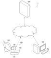
- FIG. 1 is a schematic diagram showing a configuration of a trigger notification system according to a first embodiment.
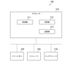
- FIG. 2 is a schematic block diagram showing the configuration of a control device according to the first embodiment.
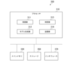
- FIG. 2 is a schematic block diagram showing a configuration of a management server according to the first embodiment.
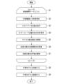
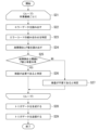
- 10 is a flowchart showing a model generation process by the management server according to the first embodiment.
- FIG. 2 is a diagram illustrating an example of a prediction model according to the first embodiment.
- 10 is a flowchart showing a trigger generation process by the management server according to the first embodiment.
- 13 is a flowchart showing a model generation process by a management server according to a second embodiment.
- FIG. 11 is a diagram illustrating an example of a prediction model according to the second embodiment.
- 10 is a flowchart showing a trigger generation process by the management server according to the first embodiment.
- Fig. 1 is a schematic diagram showing the configuration of a trigger notification system 1 according to a first embodiment.
- the trigger notification system 1 determines whether or not inspection of a work machine 100 is necessary, and presents to a maintenance person the work machines 100 for which it has been determined that inspection is necessary. In other words, the trigger notification system 1 notifies the maintenance person of a trigger for the inspection of the work machine 100.
- the maintenance person can recognize the appropriate timing for inspecting the work machine 100 by the trigger notified from the trigger notification system 1.
- the trigger notification system 1 includes a work machine 100, a management server 300, and a maintenance terminal 500.
- the work machine 100, the management server 300, and the maintenance terminal 500 are connected so as to be able to communicate with each other via a network.
- the work machine 100 is, for example, a hydraulic excavator, it operates at a construction site and performs work such as excavating soil and sand.
- the work machine 100 shown in FIG. 1 is a hydraulic excavator, but in other embodiments, it may be another work machine. Examples of work machines 100 include bulldozers, dump trucks, forklifts, wheel loaders, and motor graders.
- the work machine 100 monitors the condition of its own vehicle, and transmits error data to the management server 300 if the condition is not as desired.
- the management server 300 determines the work machine 100 to be inspected based on the error data of the work machine 100 .
- Management server 300 stores error data of the work machine 100 and a history of inspection information of the work machine 100.
- Management server 300 generates a prediction model that predicts the presence or absence of a malfunction of the work machine 100, based on the error data and the history of inspection information.
- Management server 300 determines the work machine 100 to be inspected based on the prediction model, and transmits trigger information indicating the work machine 100 to be inspected to the maintenance person terminal 500.
- management server 300 is an example of a model generating device
- management server 300 is an example of a determination device.
- the maintenance person terminal 500 displays or prints the trigger information generated by the management server 300.
- the maintenance person terminal 500 also accepts input of inspection result data indicating the results of the inspection of the work machine 100 by the maintenance person, and transmits it to the management server 300.
- the inspection result data includes the date and time of the inspection, the presence or absence of a malfunction, and the details of the inspection and the malfunction.
- the work machine 100 includes a running body 110 , a rotating body 120 , a work implement 130 , and a control device 140 .
- the running bodies 110 support the work machine 100 so that the work machine 100 can run.
- the running bodies 110 are, for example, a pair of left and right caterpillar tracks.
- the rotating body 120 is supported by the running body 110 so as to be capable of rotating about a rotation center.
- the working machine 130 is supported on the front part of the revolving body 120 so as to be drivable in the vertical direction.
- the working machine 130 is hydraulically driven.
- the part of the revolving body 120 to which the working machine 130 is attached is referred to as the front part.
- the control device 140 controls the traveling body 110, the rotating body 120, and the work machine 130 based on an operation by an operator.
- the control device 140 is provided inside the driver's cab, for example.
- the control device 140 is an example of a fall risk presentation device.
- the work machine 100 is equipped with a number of sensors 141 for detecting the working state of the work machine 100.
- the work machine 100 is equipped with a service meter, an engine speed sensor, an exhaust temperature sensor, an oil temperature sensor, an oil pressure sensor, an inclination sensor, etc.
- FIG. 2 is a schematic block diagram showing the configuration of the control device 140 according to the first embodiment.
- the control device 140 is a computer that includes a processor 210 , a main memory 230 , a storage 250 , and an interface 270 .
- Storage 250 is a non-transitory tangible storage medium. Examples of storage 250 include a magnetic disk, an optical disk, a magneto-optical disk, and a semiconductor memory. Storage 250 may be an internal medium directly connected to the bus of control device 140, or an external medium connected to control device 140 via interface 270 or a communication line. Storage 250 stores a program for controlling work machine 100.
- the program may be for realizing part of the functions to be performed by the control device 140.
- the program may be for realizing the functions by combining with other programs already stored in the storage 250 or in combination with other programs implemented in other devices.
- the control device 140 may include a custom LSI (Large Scale Integrated Circuit) such as a PLD (Programmable Logic Device) in addition to or instead of the above configuration.
- PLDs include PAL (Programmable Array Logic), GAL (Generic Array Logic), CPLD (Complex Programmable Logic Device), and FPGA (Field Programmable Gate Array).
- part or all of the functions realized by the processor may be realized by the integrated circuit.
- the processor 210 executes the program to function as an acquisition unit 211, a determination unit 212, and a transmission unit 213.
- the acquisition unit 211 acquires measurement values from each of the multiple sensors 141 .
- the determination unit 212 determines whether or not an error exists based on the measurement value acquired by the acquisition unit 211.
- the determination unit 212 determines that an error exists when the measurement value exceeds a predetermined range.
- the determination unit 212 also determines that an error exists when the acquisition unit 211 cannot acquire a measurement value from the sensor 141.
- the determination unit 212 identifies an error code that indicates the content of the error.
- the transmission unit 213 transmits error data indicating the error detected by the determination unit 212 to the management server 300.
- the error data includes identification information of the work machine 100, the time the error occurred, and an error code.
- the transmission unit 213 transmits the error data to the management server 300 at a specified transmission timing.
- the transmission unit 213 may transmit the error data by batch processing, or may transmit it to the management server 300 in real time.
- the acquisition unit 211 records the error data in the storage 250, and the transmission unit 213 transmits it to the management server 300. Note that in order to reduce the amount of communication, the transmission unit 213 may compress and transmit this history data as necessary.
- the transmission unit 213 may not transmit error data for errors other than the first error, even if an error related to the same error code occurs multiple times within a predetermined notification suppression time. Specifically, if an error with the same error code occurs within a predetermined notification suppression time (e.g., 20 hours) from the detection time of the error for which the previous error data was transmitted, the transmission unit 213 does not notify the error. For example, a case will be described in which errors related to tilt occur at midnight, 10:00, and 22:00. The error detected at midnight is the first error. Therefore, the transmission unit 213 transmits error data related to the error detected at midnight to the management server 300.
- a predetermined notification suppression time e.g. 20 hours
- the error detected at 10:00 is an error related to the same error code as the error detected at midnight, and the notification suppression time of 20 hours has not passed since the detection. Therefore, the transmission unit 213 does not transmit error data related to the error detected at 10:00.
- the error detected at 22:00 is an error related to the same error code as the error detected at midnight, but the notification suppression time of 20 hours has passed since the detection. Therefore, the transmission unit 213 transmits error data related to the error detected at 10 p.m. to the management server 300.
- FIG. 3 is a schematic block diagram showing the configuration of the management server 300 according to the first embodiment.
- the management server 300 is a computer including a processor 310 , a main memory 330 , a storage 350 , and an interface 370 .
- Storage 350 is a non-transitory tangible storage medium. Examples of storage 350 include a magnetic disk, an optical disk, a magneto-optical disk, and a semiconductor memory. Storage 350 may be an internal medium directly connected to the bus of management server 300, or an external medium connected to management server 300 via interface 370 or a communication line. Storage 350 stores a program for generating an incident report.
- the program may be for realizing some of the functions to be performed by the management server 300.
- the program may be for realizing the functions by combining with other programs already stored in the storage 350, or by combining with other programs implemented in other devices.
- the management server 300 may include a custom LSI in addition to or instead of the above configuration. In this case, some or all of the functions realized by the processor 310 may be realized by the integrated circuit. Also, in other embodiments, the management server 300 may be realized by a computer virtualized on one or more computers.
- the processor 310 executes the program to function as a receiving unit 311, a model generating unit 312, a determining unit 313, and a transmitting unit 314.
- the receiving unit 311 receives error data from the work machine 100.
- the receiving unit 311 records the received error data in the storage 350.
- the receiving unit 311 receives the inspection result data from the maintenance person terminal 500.
- the receiving unit 311 records the received inspection result data in the storage 350.
- the maintenance person performs a direct inspection of the work machine 100 to determine whether or not there is a malfunction, and generates the inspection result data by inputting the determination result to the maintenance person terminal 500.
- the direct inspection is not necessarily performed when an error code occurs, but is performed in response to some trigger, such as when the maintenance person receives a request from the site supervisor.
- the receiving unit 311 receives error data that occurred immediately before the maintenance person performed the direct inspection, and inspection result data that indicates the result of the direct inspection.
- the model generation unit 312 generates a prediction model for predicting the presence or absence of a malfunction of the work machine 100 from the combination of error codes output by the work machine 100, based on the past error data and inspection result data recorded in storage 350. Specifically, the model generation unit 312 generates a prediction model, which is a table showing the failure rate and P value for each combination pattern of error codes, by cross-tabulating the error codes and the presence or absence of malfunctions.
- the P value is the probability that a certain combination pattern of error codes will have a failure rate in a probability density distribution that represents the failure rate when it is assumed that a malfunction occurs regardless of the error code combination.
- the model generation unit 312 records the created prediction model in storage 350.
- the determination unit 313 determines whether or not an inspection of the work machine 100 is necessary based on the error data received from the work machine 100 within the most recent target period (e.g., the most recent 30 hours) and the prediction model recorded in the storage 350.
- the target period is a period of a predetermined time in the past starting from the present, and is at least a period longer than the notification suppression time of the same error by the work machine 100.
- the determination unit 313 receives error data related to error codes A, B, and C during the target period, it reads out the failure rate and P value associated with the combination of error codes A, B, and C.
- the failure rate is a value with the number of inspections that occurred when the combination of error codes appeared in the past as the denominator and the number of failures that were found as the numerator for the combination of error codes.
- the determination unit 313 determines that an inspection is necessary when the read failure rate is equal to or greater than a predetermined threshold value (e.g., 70%) and the read P value satisfies a predetermined significance level (e.g., 5%). On the other hand, if the read failure rate is less than a predetermined threshold value, or if the read P value does not meet a predetermined significance level, the judgment unit 313 judges that an inspection is unnecessary.
- the P value not meeting the significance level indicates that the combination of error codes is highly likely not to be related to a failure.
- An example of a combination of error codes A, B, and C that can occur in parallel is error code A being an oil temperature abnormality, error code B being a fuel injector abnormality, and error code C being a coolant noise abnormality.
- the transmission unit 314 transmits a list indicating the work machines 100 that require inspection among the multiple work machines 100 as trigger data to the maintenance terminal 500 based on the judgment result of the judgment unit 313.
- the list includes the necessity of inspection as well as the failure rate and P value read by the judgment unit 313.
- the maintenance person can recognize the work machines 100 that require inspection by the trigger data displayed on the maintenance terminal 500.
- the receiving unit 311 of the management server 300 records the error data in the storage 350 every time it receives error data from the work machine 100, and records the inspection result data in the storage 350 every time it receives inspection result data from the maintenance terminal 500.
- FIG. 4 is a flowchart showing the model generation process by the management server 300 according to the first embodiment.
- the management server 300 receives an instruction to generate a predictive model from an administrator, it executes the process shown in FIG. 4.
- the model generation unit 312 of the management server 300 selects each piece of inspection result data recorded in the storage 350 (step S1), and executes the processes of steps S2 to S7 for each piece of inspection result data.
- the model generation unit 312 identifies the work machine 100 to be inspected and the date and time of the inspection from the selected inspection result data (step S2).
- the model generation unit 312 reads from the storage 350 the error data related to the identified work machine 100 that occurred during a target period ending at the identified date and time (for example, the period from 30 hours before the identified date and time to the identified date and time) (step S3).
- the model generation unit 312 identifies the combination of error codes that occurred during the target period from the read error data (step S4).
- the model generation unit 312 identifies all error code patterns that can be composed of the error codes related to the identified combinations (step S5). For example, if the model generation unit 312 identifies the error code combination ⁇ A, B, C ⁇ in step S4, it identifies the error code patterns ⁇ A ⁇ , ⁇ B ⁇ , ⁇ C ⁇ , ⁇ A, B ⁇ , ⁇ B, C ⁇ , ⁇ A, C ⁇ , ⁇ A, B, C ⁇ in step S5.
- the model generation unit 312 updates the failure rate of each identified error code pattern based on the presence or absence of a failure indicated by the inspection result data selected in step S1 (step S6).
- the model generation unit 312 reads the error occurrence status for each inspection indicated by the inspection result data selected in step S1, and recalculates and updates the failure rate for each error code pattern corresponding to the error occurrence status.
- the failure rate is calculated by using the number of inspections performed during the period when the combination of error codes related to the error code pattern appears as the denominator and the number of failures found as the numerator. Specifically, for the failure rate of each error code pattern, the model generation unit 312 adds 1 to the denominator and numerator if the inspection result data indicates that there is a failure, and adds 1 to the denominator if the inspection result data indicates that there is no failure.
- the model generation unit 312 updates the P value for each error code pattern identified in step S5 (step S7).
- the failure rate and P value are calculated by forming a population for each model of the work machine 100.
- the failure rate and P value may be calculated by forming a population not only for each model, but also for each classification such as vehicle rank or region.
- the model generation unit 312 Based on the calculation results from steps S1 to S7, the model generation unit 312 generates a prediction model, which is a table showing the failure rate and P value for each error code pattern (step S8).
- the model generation unit 312 records the generated prediction model in the storage 350 (step S9).
- FIG. 5 is a diagram showing an example of a prediction model according to the first embodiment.
- FIG. 5 shows an example in which there are three types of error codes, A, B, and C.
- the prediction model may be an extraction of only those combinations of all error codes whose failure rate is equal to or exceeds a predetermined threshold value (e.g., 70%) and whose read P value satisfies a predetermined significance level (e.g., 5%).
- a predetermined threshold value e.g. 70%
- a predetermined significance level e.g., 5%
- FIG. 6 is a flowchart showing the trigger generation process by the management server 300 according to the first embodiment.
- the management server 300 executes the process shown in FIG. 6 at a predetermined interval.
- the determination unit 313 of the management server 300 selects the multiple work machines 100 one by one (step S21), and executes the processes of steps S22 to S27 for each work machine 100.
- the determination unit 313 reads out from the storage 350 the error data related to the selected work machine 100 that occurred during a target period ending at the current time (for example, the period from 30 hours before the current time to the current time) (step S22).
- the determination unit 313 identifies the combination of error codes that occurred during the target period from the read error data (step S23).
- the determination unit 313 reads out the failure rate and P value associated with the combination of error codes identified in step S23 (step S24).
- the determination unit 313 determines whether the read failure rate is equal to or greater than a predetermined threshold (e.g., 70%) and whether the read P value is equal to or greater than a predetermined significance level (e.g., 5%) (step S25). If the failure rate is equal to or greater than the threshold and the P value is equal to or greater than the significance level (step S25: YES), the determination unit 313 determines that an inspection is required for the work machine 100 selected in step S21 (step S26). On the other hand, if the failure rate is less than the threshold or the P value is less than the significance level (step S25: NO), the determination unit 313 determines that an inspection is not required for the work machine 100 selected in step S21 (step S27).
- the transmission unit 314 Based on the determination results from steps S21 to S27, the transmission unit 314 generates a list indicating the work machines 100 that require inspection among the multiple work machines 100 as trigger data (step S28).
- the trigger data includes the failure rate and P value read by the determination unit 313 in addition to the necessity of inspection.
- the transmission unit 314 transmits the trigger data to the maintenance terminal 500 (step S29).
- the transmission unit 314 transmits the trigger data to, for example, the terminal of a maintenance person in charge of maintenance service of the work machines 100 that require inspection. Note that in other embodiments, the transmission unit 314 may transmit the trigger data to the owner of the work machine 100, or may transmit the trigger data to a monitor provided on the work machine 100 to notify the operator.
- the management server 300 executes, for the inspection of the work machine 100, an inspection information acquisition step of acquiring the time the inspection was performed and the presence or absence of a malfunction revealed by the inspection results, an error acquisition step of acquiring a combination of error codes output from the control device 140 of the work machine 100, and a generation step of generating a prediction model for predicting the presence or absence of a malfunction from the combination of error codes, based on the time the inspection was performed, the presence or absence of a malfunction, and the combination of error codes.
- This enables the management server 300 to generate a prediction model that predicts the presence or absence of a malfunction based on the history of past error data and inspection results. In other words, the management server 300 can generate a prediction model for accurately determining whether or not an inspection of the work machine 100 is necessary from an error code based on past inspection results of the work machine 100.
- the management server 300 also executes an error acquisition step of acquiring a combination of error codes output from the control device 140 of the work machine 100, and an output step of outputting information regarding the necessity of inspection of the work machine 100 based on the combination of the prediction model and the error code. This allows the management server 300 to accurately determine the necessity of inspection of the work machine 100 from the error code based on the past inspection results of the work machine 100.
- the management server 300 according to the first embodiment generates a prediction model by cross-tabulation based on the inspection result data.
- the management server 300 according to the second embodiment generates a prediction model by cross-tabulation based on the error code of the work machine 100.
- the configuration of the trigger notification system 1 according to the second embodiment is the same as that of the first embodiment.
- the second embodiment differs from the first embodiment in the method of generating a prediction model by the management server 300.
- the receiving unit 311 of the management server 300 records the error data in the storage 350 every time it receives error data from the work machine 100, and records the inspection result data in the storage 350 every time it receives inspection result data from the maintenance terminal 500.
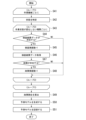
- FIG. 7 is a flowchart showing the model generation process by the management server 300 according to the second embodiment.
- the management server 300 receives an instruction to generate a predictive model from an administrator, it executes the process shown in FIG. 7.
- the model generation unit 312 of the management server 300 selects the work machines 100 one by one (step S41), and executes the processing of steps S42 to S48 for each work machine 100.
- the model generation unit 312 identifies the state of the work machine 100 represented by the combination of error codes detected in a target period ending at a plurality of times obtained by dividing the period from the time related to the oldest error data recorded in the storage 350 to the current time into predetermined time intervals (step S42).
- the state of the work machine 100 is represented as a vector representing the pattern of the combination of error codes. For example, if there are five types of error codes, A, B, C, D, and E, and error data related to error codes A, B, and E exists in the target period, the state of the work machine 100 is represented as ⁇ 1, 1, 0, 0, 1 ⁇ .
- the model generation unit 312 selects each of the periods in which the work state identified in step S42 does not change (step S43), and executes the processing of steps S44 to S48 below for each period. For example, if the state of the work machine 100 is ⁇ 1, 0, 0, 0, 0 ⁇ at times t1, t2, and t3, the state of the work machine 100 is ⁇ 1, 1, 0, 0, 0 ⁇ at times t4 and t5, and the state of the work machine 100 is ⁇ 1, 1, 0, 0, 1 ⁇ at times t6, t7, and t8, the model generation unit 312 selects the period from time t1 to time t3, the period from time t4 to time t5, and the period from time t6 to time t8, respectively.
- the model generation unit 312 determines whether or not there is inspection result data related to the work machine 100 selected in step S41 that was generated during the period selected in step S43 (step S44). If there is inspection result data generated during the period selected in step S43 (step S44: YES), the model generation unit 312 adds 1 to the number of inspection results for the state related to the period (step S45). The model generation unit 312 acquires all of the inspection result data related to the work machine 100 selected in step S41 that was generated during the period selected in step S43 (step S46). The model generation unit 312 determines whether or not there is one or more pieces of inspection result data in which a fault has been detected in the acquired inspection result data (step S47). If there is one or more pieces of inspection result data in which a fault has been detected (step S47: YES), the model generation unit 312 adds 1 to the number of failure results for the state related to the period (step S48).
- step S44 NO
- step S47 NO
- the model generation unit 312 does not add up the number of actual faults related to the state of the work machine 100 related to that period.
- the model generation unit 312 calculates the failure rate by dividing the number of actual failures by the number of actual inspections for each combination pattern of error codes (step S49). The model generation unit 312 then generates a prediction model that associates at least the failure rate and the number of actual inspections for each combination pattern of error codes (step S50). The model generation unit 312 records the generated prediction model in the storage 350 (step S51).
- Figure 8 is a diagram showing an example of a prediction model according to the second embodiment. Figure 8 shows an example when there are three types of error codes.
- FIG. 9 is a flowchart showing the trigger generation process by the management server 300 according to the first embodiment.
- the management server 300 executes the process shown in FIG. 9 at predetermined intervals.
- the determination unit 313 of the management server 300 selects the multiple work machines 100 one by one (step S61), and executes the processing of steps S62 to S69 for each work machine 100.
- the determination unit 313 reads from the storage 350 the error data related to the selected work machine 100 that occurred during a target period ending at the current time (for example, the period from 30 hours before the current time to the current time) (step S62).
- the determination unit 313 identifies a combination of error codes that occurred during the target period from the read error data (step S63).
- the determination unit 313 reads out the failure rate and the number of inspections associated with the combination of error codes identified in step S63 (step S64).
- the determination unit 313 determines whether the read failure rate is equal to or greater than a predetermined threshold value (e.g., 70%) (step S65). If the failure rate is equal to or greater than the threshold value (step S65: YES), the determination unit 313 determines that an inspection is required for the work machine 100 selected in step S61 (step S66). Furthermore, the determination unit 313 determines whether or not the read number of inspection records is less than a predetermined threshold (e.g., 5 records) (Step S67).
- a predetermined threshold e.g., 5 records
- Step S67 determines that it is preferable to inspect the work machine 100 selected in Step S61 for data collection (Step S68).
- the determination unit 313 determines that inspection is not necessary for the work machine 100 selected in step S21 (step S69).
- the transmission unit 314 generates a list indicating the work machines 100 that require inspection among the multiple work machines 100 based on the determination results from steps S61 to S69 as trigger data (step S70).
- the trigger data includes the failure rate and number of inspections read by the determination unit 313.
- the transmission unit 314 transmits the trigger data to the maintenance terminal 500 (step S71).
- the management server 300 determines, for each period in which the combination of error codes does not change, whether or not at least one fault has been found in that period, and generates a prediction model by statistical processing based on the number of periods in which at least one fault has been found. In other words, even if multiple inspections are performed in a period in which the combination of error codes does not change, the management server 300 counts the inspection record as 1. This makes it possible for the management server 300 to prevent bias in the weighting of the inspection response even if multiple inspections are performed in response to one fault. Furthermore, because the management server 300 identifies the combination of error codes as the state of the work machine 100, it outputs one fault rate regardless of the number of error codes generated by the work machine 100.
- the management server 300 executes a step of identifying combinations of error codes that have few inspection records. This makes it possible to prompt the maintenance personnel to collect data on the condition of the work machine 100 where the accuracy of the prediction model is low due to a lack of data.
- the management server 300 may be configured by a single computer, or the configuration of the management server 300 may be divided and arranged on multiple computers, and the multiple computers may cooperate with each other to function as the management server 300.
- the function of the management server 300 as a model generating device that generates a predictive model and the function as a determination device that determines whether or not an inspection is necessary based on the predictive model may be implemented in separate computers.
- the management server 300 generates a prediction model by a statistical process called cross-tabulation, but is not limited to this.
- the management server 300 may generate a prediction model by a statistical process using a machine learning model such as a neural network model.
- the management server 300 generates a combination of the state of the work machine 100 (combination of error codes) at the inspection time and the presence or absence of a malfunction as a learning dataset for each piece of inspection performance data. Then, the management server 300 trains the parameters of an estimation model, which is a machine learning model, from the learning dataset so that the state of the work machine 100 is used as input and the malfunction rate is used as output. Through such statistical process, the management server 300 can generate a prediction model using a machine learning model.
- the prediction model according to the above-described embodiment represents the relationship between the failure rate and the P value for each error code pattern as shown in FIG. 5, but in other embodiments, this is not limited to this.
- the prediction model according to other embodiments may store the failure rate and P value in addition to the failure rate and the P value, and may further associate the failure content with each other.
- the prediction model according to other embodiments may store the failure rate and P value for each type of failure.
Landscapes
- Engineering & Computer Science (AREA)
- Business, Economics & Management (AREA)
- Human Resources & Organizations (AREA)
- Entrepreneurship & Innovation (AREA)
- Operations Research (AREA)
- General Engineering & Computer Science (AREA)
- Civil Engineering (AREA)
- Economics (AREA)
- Mining & Mineral Resources (AREA)
- Marketing (AREA)
- Structural Engineering (AREA)
- Quality & Reliability (AREA)
- Strategic Management (AREA)
- Tourism & Hospitality (AREA)
- Physics & Mathematics (AREA)
- General Business, Economics & Management (AREA)
- General Physics & Mathematics (AREA)
- Theoretical Computer Science (AREA)
- Management, Administration, Business Operations System, And Electronic Commerce (AREA)
Abstract
モデル生成装置は、検査情報取得ステップと、エラー取得ステップと、生成ステップを実行する。検査情報取得ステップでは、作業機械の検査について、検査を実行した時刻と検査の結果により判明した故障の有無とを取得する。エラー取得ステップでは、作業機械の制御装置から検査を実行した時刻よりも前の時間に出力されたエラーコードの組み合わせを取得する。作業機械の制御装置は、作業機械の状態が所望の状態でない場合にエラーの種別を表すエラーコードを出力する。生成ステップでは、故障の有無と、検査を実行した時刻よりも前の時間に出力されたエラーコードの組み合わせとに基づいて、エラーコードの組み合わせから故障の有無を予測するための予測モデルを生成する。
Description
本開示は、モデル生成装置、判定装置および判定方法に関する。
本願は、2023年7月6日に日本に出願された特願2023-111640号について優先権を主張し、その内容をここに援用する。
本願は、2023年7月6日に日本に出願された特願2023-111640号について優先権を主張し、その内容をここに援用する。
作業機械に搭載された制御装置は、センサなどを介して作業機械の状態を監視し、作業機械の状態が所望の状態でない場合に、エラーを通知する。エラーの通知には、エラーの内容を表すエラーコードが付されており、保守者は当該エラーコードを読み取って作業機械の検査の要否を検討する。特許文献1には、エラーコードから作業機械の異常度合いを判断する技術が開示されている。
エラーは、センサの計測値が所定の範囲を超えたときや、通信などの制御に失敗したときに出力される。そのため、エラーの発生は必ずしも作業機械の故障を表しているわけではない。そのため、保守者はエラーコードから作業機械の検査の要否を検討することが困難である。また保守者の経験によって検討の精度が異なる可能性がある。
本開示の目的は、作業機械の過去の検査結果およびエラーコードの発生状況に基づいて、エラーコードから作業機械の検査の要否を精度よく決定するためのモデル生成装置、判定装置および判定方法を提供することにある。
本開示の目的は、作業機械の過去の検査結果およびエラーコードの発生状況に基づいて、エラーコードから作業機械の検査の要否を精度よく決定するためのモデル生成装置、判定装置および判定方法を提供することにある。
本発明の一態様によれば、モデル生成装置は、プロセッサを備え、前記プロセッサは、作業機械の検査について、前記検査を実行した時刻と前記検査の結果により判明した故障の有無とを取得する検査情報取得ステップと、前記作業機械の状態が所望の状態でない場合にエラーの種別を表すエラーコードを出力する前記作業機械の制御装置から前記検査を実行した時刻よりも前の時間に出力された前記エラーコードの組み合わせを取得するエラー取得ステップと、前記故障の有無と前記検査を実行した時刻よりも前の時間に出力された前記エラーコードの組み合わせとに基づいて、前記エラーコードの組み合わせから前記故障の有無を予測するための予測モデルを生成する生成ステップとを実行する。
上記態様によれば、予測モデルを用いることで、作業機械の過去の検査結果に基づいて、エラーコードから作業機械の検査の要否を精度よく決定することができる。
〈第一実施形態〉
《トリガ通知システム1の構成》
以下、図面を参照しながら実施形態について詳しく説明する。
図1は、第一実施形態に係るトリガ通知システム1の構成を示す概略図である。トリガ通知システム1は、作業機械100の検査の要否を判定し、検査が必要であると判定された作業機械100を保守者に提示する。つまり、トリガ通知システム1は、保守者に作業機械100の検査のトリガを通知する。保守者は、トリガ通知システム1から通知されたトリガによって適切な作業機械100の検査タイミングを認識することができる。
《トリガ通知システム1の構成》
以下、図面を参照しながら実施形態について詳しく説明する。
図1は、第一実施形態に係るトリガ通知システム1の構成を示す概略図である。トリガ通知システム1は、作業機械100の検査の要否を判定し、検査が必要であると判定された作業機械100を保守者に提示する。つまり、トリガ通知システム1は、保守者に作業機械100の検査のトリガを通知する。保守者は、トリガ通知システム1から通知されたトリガによって適切な作業機械100の検査タイミングを認識することができる。
トリガ通知システム1は、作業機械100、管理サーバ300および保守者端末500を備える。作業機械100、管理サーバ300および保守者端末500は、ネットワークを介して通信可能に接続される。
作業機械100は、例えばそれが油圧ショベルである場合、施工現場にて稼働し、土砂の掘削作業などを行う。図1に示す作業機械100は、油圧ショベルであるが、他の実施形態においては、他の作業機械であってもよい。作業機械100の例としては、ブルドーザ、ダンプトラック、フォークリフト、ホイールローダ、モータグレーダなどが挙げられる。作業機械100は、自車両の状態を監視し、状態が所望の状態でない場合に管理サーバ300にエラーデータを送信する。
管理サーバ300は、作業機械100のエラーデータに基づいて、検査すべき作業機械100を決定する。
管理サーバ300は、作業機械100のエラーデータおよび作業機械100の検査情報の履歴を記憶する。管理サーバ300は、エラーデータおよび検査情報の履歴に基づいて、作業機械100の故障の有無を予測する予測モデルを生成する。管理サーバ300は、予測モデルに基づいて、検査を行うべき作業機械100を決定し、保守者端末500に検査すべき作業機械100を示すトリガ情報を送信する。つまり、管理サーバ300はモデル生成装置の一例であり、また管理サーバ300は判定装置の一例である。
管理サーバ300は、作業機械100のエラーデータおよび作業機械100の検査情報の履歴を記憶する。管理サーバ300は、エラーデータおよび検査情報の履歴に基づいて、作業機械100の故障の有無を予測する予測モデルを生成する。管理サーバ300は、予測モデルに基づいて、検査を行うべき作業機械100を決定し、保守者端末500に検査すべき作業機械100を示すトリガ情報を送信する。つまり、管理サーバ300はモデル生成装置の一例であり、また管理サーバ300は判定装置の一例である。
保守者端末500は、管理サーバ300が生成したトリガ情報を表示し、または印刷する。また保守者端末500は、保守者による作業機械100の検査結果を示す検査結果データの入力を受け付け、管理サーバ300に送信する。検査結果データは、検査の日時と、故障の有無、検査および故障の内容を含む。
《作業機械100の構成》
作業機械100は、走行体110、旋回体120、作業機130、制御装置140を備える。
走行体110は、作業機械100を走行可能に支持する。走行体110は、例えば左右1対の無限軌道である。
旋回体120は、走行体110に旋回中心回りに旋回可能に支持される。
作業機130は、旋回体120の前部に上下方向に駆動可能に支持される。作業機130は、油圧により駆動する。ここで、旋回体120のうち作業機130が取り付けられる部分を前部という。また、旋回体120について、前部を基準に、反対側の部分を後部、左側の部分を左部、右側の部分を右部という。
制御装置140は、オペレータの操作に基づいて、走行体110、旋回体120、および作業機130を制御する。制御装置140は、例えば運転室の内部に設けられる。制御装置140は、転倒リスク提示装置の一例である。
作業機械100は、走行体110、旋回体120、作業機130、制御装置140を備える。
走行体110は、作業機械100を走行可能に支持する。走行体110は、例えば左右1対の無限軌道である。
旋回体120は、走行体110に旋回中心回りに旋回可能に支持される。
作業機130は、旋回体120の前部に上下方向に駆動可能に支持される。作業機130は、油圧により駆動する。ここで、旋回体120のうち作業機130が取り付けられる部分を前部という。また、旋回体120について、前部を基準に、反対側の部分を後部、左側の部分を左部、右側の部分を右部という。
制御装置140は、オペレータの操作に基づいて、走行体110、旋回体120、および作業機130を制御する。制御装置140は、例えば運転室の内部に設けられる。制御装置140は、転倒リスク提示装置の一例である。
作業機械100は、作業機械100の作業状態を検出するための複数のセンサ141を備える。具体的には、作業機械100は、サービスメータ、エンジン回転数センサ、排気温度センサ、油温センサ、油圧センサ、傾斜センサなどを備える。
図2は、第一実施形態に係る制御装置140の構成を示す概略ブロック図である。
制御装置140は、プロセッサ210、メインメモリ230、ストレージ250、インタフェース270を備えるコンピュータである。
制御装置140は、プロセッサ210、メインメモリ230、ストレージ250、インタフェース270を備えるコンピュータである。
ストレージ250は、一時的でない有形の記憶媒体である。ストレージ250の例としては、磁気ディスク、光ディスク、光磁気ディスク、半導体メモリ等が挙げられる。ストレージ250は、制御装置140のバスに直接接続された内部メディアであってもよいし、インタフェース270または通信回線を介して制御装置140に接続される外部メディアであってもよい。ストレージ250は、作業機械100を制御するためのプログラムを記憶する。
プログラムは、制御装置140に発揮させる機能の一部を実現するためのものであってもよい。例えば、プログラムは、ストレージ250に既に記憶されている他のプログラムとの組み合わせ、または他の装置に実装された他のプログラムとの組み合わせによって機能を発揮させるものであってもよい。なお、他の実施形態においては、制御装置140は、上記構成に加えて、または上記構成に代えてPLD(Programmable Logic Device)などのカスタムLSI(Large Scale Integrated Circuit)を備えてもよい。PLDの例としては、PAL(Programmable Array Logic)、GAL(Generic Array Logic)、CPLD(Complex Programmable Logic Device)、FPGA(Field Programmable Gate Array)が挙げられる。この場合、プロセッサによって実現される機能の一部または全部が当該集積回路によって実現されてよい。
プロセッサ210は、プログラムを実行することで、取得部211、判定部212、送信部213として機能する。
取得部211は、複数のセンサ141からそれぞれ計測値を取得する。
判定部212は、取得部211が取得した計測値に基づいてエラーの有無を判定する。判定部212は、計測値が所定の範囲を超える場合にエラーがあると判定する。また判定部212は、取得部211がセンサ141から計測値を取得できない場合に、エラーがあると判定する。判定部212は、エラーの内容を表すエラーコードを特定する。
判定部212は、取得部211が取得した計測値に基づいてエラーの有無を判定する。判定部212は、計測値が所定の範囲を超える場合にエラーがあると判定する。また判定部212は、取得部211がセンサ141から計測値を取得できない場合に、エラーがあると判定する。判定部212は、エラーの内容を表すエラーコードを特定する。
送信部213は、判定部212によって検出されたエラー示すエラーデータを、管理サーバ300に送信する。エラーデータは、作業機械100の識別情報と、エラーの発生時刻と、エラーコードとを含む。送信部213は、所定の送信タイミングで、エラーデータを管理サーバ300に送信する。送信部213はエラーデータをバッチ処理によって送信してもよいし、リアルタイムに管理サーバ300に送信してもよい。エラーデータをバッチ処理にて送信する場合、取得部211はストレージ250にエラーデータを記録し、送信部213はこれを管理サーバ300に送信する。なお、通信量の削減のために、送信部213は、必要に応じてこれら履歴データは圧縮して送信してもよい。
また、送信部213は、通信量の削減のために、同一のエラーコードに係るエラーが所定の通知抑制時間以内に複数回発生したとしても、初回のエラー以外についてはエラーデータを送信しなくてもよい。具体的には、送信部213は、前回エラーデータを送信したエラーの検出時刻から所定の通知抑制時間(例えば20時間)以内に、同一のエラーコードのエラーが発生した場合には、当該エラーを通知しない。例えば、0時、10時、22時に、それぞれ傾斜に係るエラーが発生した場合について説明する。0時に検出されたエラーは初回のエラーである。そのため送信部213は、0時に検出されたエラーに係るエラーデータを管理サーバ300へ送信する。10時に検出されたエラーは、0時に検出されたエラーと同一のエラーコードに係るエラーであり、また検出から通知抑制時間である20時間が経過していない。そのため、送信部213は、10時に検出されたエラーに係るエラーデータを送信しない。22時に検出されたエラーは、0時に検出されたエラーと同一のエラーコードに係るエラーであるが、検出から通知抑制時間である20時間が経過している。そのため、送信部213は、22時に検出されたエラーに係るエラーデータを管理サーバ300へ送信する。
《管理サーバ300の構成》
図3は、第一実施形態に係る管理サーバ300の構成を示す概略ブロック図である。
管理サーバ300は、プロセッサ310、メインメモリ330、ストレージ350、インタフェース370を備えるコンピュータである。
図3は、第一実施形態に係る管理サーバ300の構成を示す概略ブロック図である。
管理サーバ300は、プロセッサ310、メインメモリ330、ストレージ350、インタフェース370を備えるコンピュータである。
ストレージ350は、一時的でない有形の記憶媒体である。ストレージ350の例としては、磁気ディスク、光ディスク、光磁気ディスク、半導体メモリ等が挙げられる。ストレージ350は、管理サーバ300のバスに直接接続された内部メディアであってもよいし、インタフェース370または通信回線を介して管理サーバ300に接続される外部メディアであってもよい。ストレージ350は、インシデントレポートを生成するためのプログラムを記憶する。
プログラムは、管理サーバ300に発揮させる機能の一部を実現するためのものであってもよい。例えば、プログラムは、ストレージ350に既に記憶されている他のプログラムとの組み合わせ、または他の装置に実装された他のプログラムとの組み合わせによって機能を発揮させるものであってもよい。なお、他の実施形態においては、管理サーバ300は、上記構成に加えて、または上記構成に代えてカスタムLSIを備えてもよい。この場合、プロセッサ310によって実現される機能の一部または全部が当該集積回路によって実現されてよい。また、他の実施形態においては、管理サーバ300は、1または複数のコンピュータ上で仮想化されたコンピュータによって実現されてもよい。
プロセッサ310は、プログラムを実行することで、受信部311、モデル生成部312、判定部313、送信部314として機能する。
受信部311は、作業機械100からエラーデータを受信する。受信部311は、受信したエラーデータをストレージ350に記録する。
受信部311は、保守者端末500から検査結果データを受信する。受信部311は、受信した検査結果データをストレージ350に記録する。保守者は、作業機械100の直接検査を行って故障の有無を判断し、判断結果を保守者端末500に入力することで検査結果データを生成する。なお、直接検査は、必ずしもエラーコードが発生したときにされるのではなく、保守者が現場監督からリクエストを受けたときなど、何らかの契機に応じて行われる。受信部311は、保守者が直接検査を行ったタイミングの直近に発生したエラーデータと、当該直接検査の結果を示す検査結果データとを受信する。
受信部311は、保守者端末500から検査結果データを受信する。受信部311は、受信した検査結果データをストレージ350に記録する。保守者は、作業機械100の直接検査を行って故障の有無を判断し、判断結果を保守者端末500に入力することで検査結果データを生成する。なお、直接検査は、必ずしもエラーコードが発生したときにされるのではなく、保守者が現場監督からリクエストを受けたときなど、何らかの契機に応じて行われる。受信部311は、保守者が直接検査を行ったタイミングの直近に発生したエラーデータと、当該直接検査の結果を示す検査結果データとを受信する。
モデル生成部312は、ストレージ350に記録された過去のエラーデータおよび検査結果データに基づいて、作業機械100が出力したエラーコードの組み合わせから当該作業機械100の故障の有無を予測するための予測モデルを生成する。具体的には、モデル生成部312は、エラーコードと故障の有無とのクロス集計によって、エラーコードの組み合わせパターンごとの故障割合およびP値を示すテーブルである予測モデルを生成する。P値は、故障がエラーコードの組み合わせと無関係に発生すると仮定したときの故障割合を表す確率密度分布において、あるエラーコードの組み合わせパターンの故障割合となる確率である。モデル生成部312は、作成した予測モデルをストレージ350に記録する。
判定部313は、作業機械100から直近の対象期間(例えば、直近の30時間)内に受信されたエラーデータと、ストレージ350に記録された予測モデルとに基づいて、当該作業機械100の検査の要否を判定する。対象期間は、現在を起点にした過去の所定時間の期間であって、少なくとも作業機械100による同一エラーの通知抑制時間より長い期間である。例えば、判定部313は、対象期間に、エラーコードA、B、Cに係るエラーデータを受信した場合、エラーコードA、B、Cの組み合わせに関連付けられた故障割合およびP値を読み出す。故障割合は、エラーコードの組み合わせについて、過去に当該組み合わせが表れるときに発生した検査の数を分母とし、故障が判明した数を分子とする値である。判定部313は、読み出した故障割合が所定の閾値(例えば、70%)以上であって、かつ読み出したP値が所定の有意水準(例えば、5%)を満たす場合に、検査が必要であると判定する。他方、判定部313は、読み出した故障割合が所定の閾値未満である場合、または読み出したP値が所定の有意水準を満たさない場合には、検査が不要であると判定する。P値が有意水準を満たさないことは、当該エラーコードの組み合わせが故障に関係しない可能性が十分に高いことを表すためである。並列的に発生し得るエラーコードA、B、Cの組み合わせの例としては、エラーコードAが油温異常、エラーコードBが燃料インジェクタ異常、エラーコードCが冷却水音異常であることがあげられる。
送信部314は、判定部313の判定結果に基づいて、複数の作業機械100のうち検査が必要な作業機械100を示すリストを、トリガデータとして保守者端末500に送信する。リストには、検査の要否に加え、判定部313が読み出した故障割合およびP値が含まれる。保守者は、保守者端末500に表示されたトリガデータによって、検査が必要な作業機械100を認識することができる。
《管理サーバ300の処理》
管理サーバ300の受信部311は、作業機械100からエラーデータを受信するたびに当該エラーデータをストレージ350に記録し、保守者端末500から検査結果データを受信するたびに当該検査結果データをストレージ350に記録する。
管理サーバ300の受信部311は、作業機械100からエラーデータを受信するたびに当該エラーデータをストレージ350に記録し、保守者端末500から検査結果データを受信するたびに当該検査結果データをストレージ350に記録する。
図4は、第一実施形態に係る管理サーバ300によるモデル生成処理を示すフローチャートである。管理サーバ300は、管理者から予測モデルの生成指示を受け付けると、図4に示す処理を実行する。
まず、管理サーバ300のモデル生成部312は、ストレージ350に記録された検査結果データを1つずつ選択し(ステップS1)、各検査結果データについて、ステップS2からステップS7の処理を実行する。モデル生成部312は、選択した検査結果データから、検査対象の作業機械100と検査の日時とを特定する(ステップS2)。モデル生成部312は、特定した作業機械100に係るエラーデータであって、特定した日時を終点とする対象期間(例えば、特定した日時の30時間前から特定した日時までの期間)において発生したエラーデータを、ストレージ350から読み出す(ステップS3)。
モデル生成部312は、読み出したエラーデータから、対象期間において発生したエラーコードの組み合わせを特定する(ステップS4)。モデル生成部312は、特定した組み合わせに係るエラーコードで構成されうるエラーコードパターンをすべて特定する(ステップS5)。例えば、モデル生成部312は、ステップS4で、エラーコードの組み合わせ{A、B、C}を特定した場合、ステップS5でエラーコードパターン{A}、{B}、{C}、{A、B}、{B、C}、{A、C}、{A、B、C}を特定する。モデル生成部312は、ステップS1で選択した検査結果データが示す故障の有無に基づいて、特定した各エラーコードパターンの故障割合を更新する(ステップS6)。つまり、モデル生成部312は、ステップS1で選択した検査結果データが示す検査ごとに、エラー発生状況を読み取り、当該エラー発生状況に対応するエラーコードパターンごとに、故障割合を再計算して更新する。故障割合は、エラーコードパターンに係るエラーコードの組み合わせについて、当該組み合わせが表れる時期に実施された検査の数を分母とし、故障が判明した数を分子とする。具体的には、モデル生成部312は、各エラーコードパターンの故障割合について、検査結果データが故障があることを示す場合には分母と分子にそれぞれ1を加算し、検査結果データが故障がないことを示す場合には分母に1を加算する。また、モデル生成部312は、ステップS5で特定した各エラーコードパターンについて、P値を更新する(ステップS7)。なお、故障割合およびP値は、作業機械100の機種ごとに母集団を形成して計算される。故障割合およびP値は、機種のみならず、車格や地域などの区分ごとに母集団を形成して計算されてもよい。
モデル生成部312は、ステップS1からステップS7の計算結果に基づいて、エラーコードパターンごとの故障割合およびP値を示すテーブルである予測モデルを生成する(ステップS8)。モデル生成部312は、生成した予測モデルをストレージ350に記録する(ステップS9)。図5は、第一実施形態に係る予測モデルの例を示す図である。図5は、エラーコードがA、B、Cの3種類である場合の例を示す。なお、予測モデルは、全てのエラーコードの組み合わせのうち、故障割合が所定の閾値(例えば、70%)以上であって、かつ読み出したP値が所定の有意水準(例えば、5%)を満たすもののみを抽出したものであってもよい。
図6は、第一実施形態に係る管理サーバ300によるトリガ生成処理を示すフローチャートである。管理サーバ300は、所定の周期ごとに、図6に示す処理を実行する。
まず、管理サーバ300の判定部313は、複数の作業機械100を1つずつ選択し(ステップS21)、各作業機械100について、ステップS22からステップS27の処理を実行する。判定部313は、選択した作業機械100に係るエラーデータであって、現在時刻を終点とする対象期間(例えば、現在時刻の30時間前から現在時刻までの期間)において発生したエラーデータを、ストレージ350から読み出す(ステップS22)。
判定部313は、読み出したエラーデータから、対象期間において発生したエラーコードの組み合わせを特定する(ステップS23)。判定部313は、ステップS23で特定したエラーコードの組み合わせに関連付けられた故障割合およびP値を読み出す(ステップS24)。判定部313は、読み出した故障割合が所定の閾値(例えば、70%)以上であって、かつ読み出したP値が所定の有意水準(例えば、5%)以上であるか否かを判定する(ステップS25)。判定部313は、故障割合が閾値以上であって、かつP値が有意水準以上である場合(ステップS25:YES)、ステップS21で選択した作業機械100について検査が必要であると判定する(ステップS26)。他方、判定部313は、故障割合が閾値未満である場合、またはP値が有意水準未満である場合(ステップS25:NO)、ステップS21で選択した作業機械100について検査が不要であると判定する(ステップS27)。
送信部314は、ステップS21からステップS27による判定結果に基づいて、複数の作業機械100のうち検査が必要な作業機械100を示すリストを、トリガデータとして生成する(ステップS28)。トリガデータには、検査の要否に加え、判定部313が読み出した故障割合およびP値が含まれる。送信部314は、トリガデータを保守者端末500に送信する(ステップS29)。送信部314は、トリガデータを、例えば検査を要する作業機械100の保守サービスを担当する保守者の端末に送信する。なお、他の実施形態においては、送信部314は、作業機械100のオーナーにトリガデータを送信してよいし、オペレータに知らせるために作業機械100に備えられたモニタにトリガデータを送信してもよい。
《作用・効果》
このように、第一実施形態に係る管理サーバ300は、作業機械100の検査について、検査を実行した時刻と検査の結果により判明した故障の有無とを取得する検査情報取得ステップと、作業機械100の制御装置140から出力されたエラーコードの組み合わせを取得するエラー取得ステップと、検査を実行した時刻と、故障の有無と、エラーコードの組み合わせとに基づいて、エラーコードの組み合わせから故障の有無を予測するための予測モデルを生成する生成ステップとを実行する。
これにより、管理サーバ300は、過去のエラーデータの履歴と検査の実績とに基づいて、故障の有無を予測する予測モデルを生成することができる。つまり、管理サーバ300は、作業機械100の過去の検査結果に基づいてエラーコードから作業機械の検査の要否を精度よく決定するための予測モデルを生成することができる。
このように、第一実施形態に係る管理サーバ300は、作業機械100の検査について、検査を実行した時刻と検査の結果により判明した故障の有無とを取得する検査情報取得ステップと、作業機械100の制御装置140から出力されたエラーコードの組み合わせを取得するエラー取得ステップと、検査を実行した時刻と、故障の有無と、エラーコードの組み合わせとに基づいて、エラーコードの組み合わせから故障の有無を予測するための予測モデルを生成する生成ステップとを実行する。
これにより、管理サーバ300は、過去のエラーデータの履歴と検査の実績とに基づいて、故障の有無を予測する予測モデルを生成することができる。つまり、管理サーバ300は、作業機械100の過去の検査結果に基づいてエラーコードから作業機械の検査の要否を精度よく決定するための予測モデルを生成することができる。
また、第一実施形態に係る管理サーバ300は、作業機械100の制御装置140から出力されたエラーコードの組み合わせを取得するエラー取得ステップと、予測モデルとエラーコードの組み合わせとに基づいて作業機械100の検査の要否に関する情報を出力する出力ステップとを実行する。これにより、管理サーバ300は、作業機械100の過去の検査結果に基づいて、エラーコードから作業機械100の検査の要否を精度よく決定することができる。
〈第二実施形態〉
第一実施形態に係る管理サーバ300は、検査結果データを基準にしたクロス集計によって予測モデルを生成する。これに対し、第二実施形態に係る管理サーバ300は、作業機械100のエラーコードを基準にしたクロス集計によって予測モデルを生成する。
第一実施形態に係る管理サーバ300は、検査結果データを基準にしたクロス集計によって予測モデルを生成する。これに対し、第二実施形態に係る管理サーバ300は、作業機械100のエラーコードを基準にしたクロス集計によって予測モデルを生成する。
第二実施形態に係るトリガ通知システム1の構成は、第一実施形態と同様である。他方、第二実施形態は、管理サーバ300による予測モデルの生成方法が第一実施形態と異なる。
《管理サーバ300の処理》
管理サーバ300の受信部311は、作業機械100からエラーデータを受信するたびに当該エラーデータをストレージ350に記録し、保守者端末500から検査結果データを受信するたびに当該検査結果データをストレージ350に記録する。
管理サーバ300の受信部311は、作業機械100からエラーデータを受信するたびに当該エラーデータをストレージ350に記録し、保守者端末500から検査結果データを受信するたびに当該検査結果データをストレージ350に記録する。
図7は、第二実施形態に係る管理サーバ300によるモデル生成処理を示すフローチャートである。管理サーバ300は、管理者から予測モデルの生成指示を受け付けると、図7に示す処理を実行する。
まず、管理サーバ300のモデル生成部312は、作業機械100を1つずつ選択し(ステップS41)、各作業機械100について、ステップS42からステップS48の処理を実行する。モデル生成部312は、ストレージ350に記録された最も古いエラーデータに係る時刻から現在時刻までの期間を所定時間ごとに区切った複数の時刻について、当該時刻を終点とする対象期間において検出されたエラーコードの組み合わせによって表される作業機械100の状態を特定する(ステップS42)。作業機械100の状態は、エラーコードの組み合わせのパターンを表すベクトルとして表される。例えば、エラーコードの種類がA、B、C,D,Eの5種類であって、対象期間においてエラーコードA、B、Eに係るエラーデータが存在する場合、作業機械100の状態は{1、1、0、0、1}と表される。
モデル生成部312は、ステップS42で特定した作業状態が変化しない期間を1つずつ選択し(ステップS43)、各期間について、以下のステップS44からステップS48の処理を実行する。例えば、モデル生成部312は、時刻t1、時刻t2、時刻t3において、作業機械100の状態が{1、0、0、0、0}であって、時刻t4、時刻t5において、作業機械100の状態が{1、1、0、0、0}であって、時刻t6、時刻t7、時刻t8において、作業機械100の状態が{1、1、0、0、1}である場合、モデル生成部312は、時刻t1から時刻t3までの期間、時刻t4から時刻t5までの期間、時刻t6から時刻t8までの期間をそれぞれ選択する。
モデル生成部312は、ステップS43で選択された期間に生成された、ステップS41で選択した作業機械100に係る検査結果データが存在するか否かを判定する(ステップS44)。ステップS43で選択された期間に生成された検査結果データが存在する場合(ステップS44:YES)、モデル生成部312は、当該期間に係る状態についての検査実績数に1を加算する(ステップS45)。モデル生成部312は、ステップS43で選択された期間に生成された、ステップS41で選択した作業機械100に係る検査結果データをすべて取得する(ステップS46)。モデル生成部312は、取得した検査結果データに故障が検出されたものが1つ以上存在するか否かを判定する(ステップS47)。故障が検出された検査結果データが1つ以上存在する場合(ステップS47:YES)、モデル生成部312は、当該期間に係る状態についての故障実績数に1を加算する(ステップS48)。
なお、ステップS43で選択された期間に生成された、ステップS41で選択した作業機械100に係る検査結果データが存在しない場合(ステップS44:NO)、モデル生成部312は、当該期間に係る作業機械100の状態に係る検査実績数を加算しない。
また、ステップS43で選択された期間に生成された、ステップS41で選択した作業機械100に係る検査結果データが全てにおいて故障が検出されていない場合(ステップS47:NO)、モデル生成部312は、当該期間に係る作業機械100の状態に係る故障実績数を加算しない。
また、ステップS43で選択された期間に生成された、ステップS41で選択した作業機械100に係る検査結果データが全てにおいて故障が検出されていない場合(ステップS47:NO)、モデル生成部312は、当該期間に係る作業機械100の状態に係る故障実績数を加算しない。
モデル生成部312は、エラーコードの組み合わせパターンのそれぞれについて、故障実績数を検査実績数で除算することで、故障割合を算出する(ステップS49)。そしてモデル生成部312は、エラーコードの組み合わせパターンに、少なくとも当該パターンに係る故障割合と、検査実績数とを関連付けた予測モデルを生成する(ステップS50)。モデル生成部312は、生成した予測モデルをストレージ350に記録する(ステップS51)。図8は、第二実施形態に係る予測モデルの例を示す図である。図8は、エラーコードが3種類である場合の例を示す。
図9は、第一実施形態に係る管理サーバ300によるトリガ生成処理を示すフローチャートである。管理サーバ300は、所定の周期ごとに、図9に示す処理を実行する。
まず、管理サーバ300の判定部313は、複数の作業機械100を1つずつ選択し(ステップS61)、各作業機械100について、ステップS62からステップS69の処理を実行する。判定部313は、選択した作業機械100に係るエラーデータであって、現在時刻を終点とする対象期間(例えば、現在時刻の30時間前から現在時刻までの期間)において発生したエラーデータを、ストレージ350から読み出す(ステップS62)。
判定部313は、読み出したエラーデータから、対象期間において発生したエラーコードの組み合わせを特定する(ステップS63)。判定部313は、ステップS63で特定したエラーコードの組み合わせに関連付けられた故障割合および検査実績数を読み出す(ステップS64)。判定部313は、読み出した故障割合が所定の閾値(例えば、70%)以上であるか否かを判定する(ステップS65)。判定部313は、故障割合が閾値以上である場合(ステップS65:YES)、ステップS61で選択した作業機械100について検査が必要であると判定する(ステップS66)。
また、判定部313は、読み出した検査実績数が所定の閾値(例えば、5件)未満であるか否かを判定する(ステップS67)。判定部313は、検査実績数が閾値未満である場合(ステップS67:YES)、ステップS61で選択した作業機械100について、データ収集のために検査をすることが好ましい判定する(ステップS68)。
他方、判定部313は、故障割合が閾値未満であり、かつ検査実績数が閾値以上である場合(ステップS67:NO)、ステップS21で選択した作業機械100について検査が不要であると判定する(ステップS69)。
また、判定部313は、読み出した検査実績数が所定の閾値(例えば、5件)未満であるか否かを判定する(ステップS67)。判定部313は、検査実績数が閾値未満である場合(ステップS67:YES)、ステップS61で選択した作業機械100について、データ収集のために検査をすることが好ましい判定する(ステップS68)。
他方、判定部313は、故障割合が閾値未満であり、かつ検査実績数が閾値以上である場合(ステップS67:NO)、ステップS21で選択した作業機械100について検査が不要であると判定する(ステップS69)。
送信部314は、ステップS61からステップS69による判定結果に基づいて、複数の作業機械100のうち検査が必要な作業機械100を示すリストを、トリガデータとして生成する(ステップS70)。トリガデータには、検査の要否に加え、判定部313が読み出した故障割合および検査実績数が含まれる。送信部314は、トリガデータを保守者端末500に送信する(ステップS71)。
《作用・効果》
このように、第二実施形態に係る管理サーバ300は、エラーコードの組み合わせが変化しない期間ごとに、当該期間において少なくとも1つの故障が判明したか否かを判定し、少なくとも1つの故障が判明した期間の数に基づく統計処理によって、予測モデルを生成する。つまり、管理サーバ300は、エラーコードの組み合わせが変化しない期間について複数回の検査がなされても、検査実績を1と計数する。これにより、管理サーバ300は、1つの故障対応において複数回の検査がなされても、検査対応の重みに偏りが生じることを防ぐことができる。また、管理サーバ300は、エラーコードの組み合わせを作業機械100の状態として特定するため、作業機械100が発生するエラーコードの数に関わらず、1つの故障割合を出力する。
このように、第二実施形態に係る管理サーバ300は、エラーコードの組み合わせが変化しない期間ごとに、当該期間において少なくとも1つの故障が判明したか否かを判定し、少なくとも1つの故障が判明した期間の数に基づく統計処理によって、予測モデルを生成する。つまり、管理サーバ300は、エラーコードの組み合わせが変化しない期間について複数回の検査がなされても、検査実績を1と計数する。これにより、管理サーバ300は、1つの故障対応において複数回の検査がなされても、検査対応の重みに偏りが生じることを防ぐことができる。また、管理サーバ300は、エラーコードの組み合わせを作業機械100の状態として特定するため、作業機械100が発生するエラーコードの数に関わらず、1つの故障割合を出力する。
また、第二実施形態に係る管理サーバ300は、検査の実績が少ないエラーコードの組み合わせを特定する特定ステップを実行する。これにより、予測モデルのうちデータが少ないために精度が低い作業機械100の状態について、保守者にデータの収集を促すことができる。
〈他の実施形態〉
以上、図面を参照していくつかの実施形態について詳しく説明してきたが、具体的な構成は上述のものに限られることはなく、様々な設計変更等をすることが可能である。すなわち、他の実施形態においては、上述の処理の順序が適宜変更されてもよい。また、一部の処理が並列に実行されてもよい。
上述した実施形態に係る管理サーバ300は、単独のコンピュータによって構成されるものであってもよいし、管理サーバ300の構成を複数のコンピュータに分けて配置し、複数のコンピュータが互いに協働することで管理サーバ300として機能するものであってもよい。例えば、他の実施形態においては、管理サーバ300のうち予測モデルを生成するモデル生成装置としての機能と、予測モデルに基づいて検査の要否を判定する判定装置としての機能を別個のコンピュータに実装させてもよい。
以上、図面を参照していくつかの実施形態について詳しく説明してきたが、具体的な構成は上述のものに限られることはなく、様々な設計変更等をすることが可能である。すなわち、他の実施形態においては、上述の処理の順序が適宜変更されてもよい。また、一部の処理が並列に実行されてもよい。
上述した実施形態に係る管理サーバ300は、単独のコンピュータによって構成されるものであってもよいし、管理サーバ300の構成を複数のコンピュータに分けて配置し、複数のコンピュータが互いに協働することで管理サーバ300として機能するものであってもよい。例えば、他の実施形態においては、管理サーバ300のうち予測モデルを生成するモデル生成装置としての機能と、予測モデルに基づいて検査の要否を判定する判定装置としての機能を別個のコンピュータに実装させてもよい。
上述した実施形態に係る管理サーバ300は、クロス集計という統計処理によって予測モデルを生成するが、これに限られない。例えば、他の実施形態に係る管理サーバ300は、ニューラルネットワークモデルなどの機械学習モデルを用いた統計処理によって、予測モデルを生成してもよい。例えば、管理サーバ300は、検査実績データ毎の、当該検査時刻における作業機械100の状態(エラーコードの組み合わせ)と、故障の有無との組み合わせを、学習用データセットとして生成する。そして、管理サーバ300は、学習用データセットのうち、作業機械100の状態を入力として、故障割合を出力とするように、機械学習モデルである推定モデルのパラメータを学習させる。このような統計処理により、管理サーバ300は、機械学習モデルによって予測モデルを生成することができる。
上述した実施形態に係る予測モデルは、図5に示すようにエラーコードパターンごとの故障割合およびP値の関係を表すが、他の実施形態においては、これに限られない。例えば、他の実施形態に係る予測モデルは、故障割合およびP値に加え、さらに故障の内容を関連付けて記憶してもよい。また例えば、他の実施形態に係る予測モデルは、故障の内容別の故障割合およびP値を記憶してもよい。
上記態様によれば、予測モデルを用いることで、作業機械の過去の検査結果に基づいて、エラーコードから作業機械の検査の要否を精度よく決定することができる。
1…トリガ通知システム 100…作業機械 110…走行体 120…旋回体 130…作業機 140…制御装置 141…センサ 210…プロセッサ 211…取得部 212…判定部 213…送信部 230…メインメモリ 250…ストレージ 270…インタフェース 300…管理サーバ 310…プロセッサ 311…受信部 312…モデル生成部 313…判定部 314…送信部 330…メインメモリ 350…ストレージ 370…インタフェース 500…保守者端末
Claims (7)
- プロセッサを備え、
前記プロセッサは、
作業機械の検査について、前記検査を実行した時刻と前記検査の結果により判明した故障の有無とを取得する検査情報取得ステップと、
前記作業機械の状態が所望の状態でない場合にエラーの種別を表すエラーコードを出力する前記作業機械の制御装置から、前記検査を実行した時刻よりも前の時間に出力された前記エラーコードの組み合わせを取得するエラー取得ステップと、
前記故障の有無と、前記検査を実行した時刻よりも前の時間に出力されたエラーコードの組み合わせとに基づいて、前記エラーコードの組み合わせから前記故障の有無を予測するための予測モデルを生成する生成ステップと
を実行する
モデル生成装置。 - 前記生成ステップでは、複数の検査それぞれについて、前記故障の有無と前記検査を実行した時刻よりも前の時間に出力された前記エラーコードの組み合わせとの統計処理によって、前記予測モデルを生成する
請求項1に記載のモデル生成装置。 - 前記生成ステップでは、前記検査を実行した時刻よりも前の時間に出力された前記エラーコードの組み合わせのパターンと、前記検査それぞれにおける前記故障の有無との統計処理によって、前記予測モデルを生成する
請求項1に記載のモデル生成装置。 - 前記生成ステップでは、エラーコードの組み合わせが変化しない期間ごとに、当該期間において少なくとも1つの故障が判明したか否かを判定し、前記少なくとも1つの故障が判明した期間の数に基づく統計処理によって、前記予測モデルを生成する
請求項3に記載のモデル生成装置。 - 前記プロセッサは、
前記検査の実績が少ない前記エラーコードの組み合わせを特定する特定ステップをさらに実行する
請求項3または請求項4に記載のモデル生成装置。 - プロセッサを備え、
前記プロセッサは、
作業機械の状態が所望の状態でない場合にエラーの種別を表すエラーコードを出力する前記作業機械の制御装置から現在時刻よりも前の時間に出力された前記エラーコードの組み合わせを取得するエラー取得ステップと、
前記作業機械の検査を実行した時刻と前記検査の結果により判明した故障の有無と前記検査を実行した時刻よりも前の時間に出力された前記エラーコードの組み合わせとに基づいて生成された、前記エラーコードの組み合わせから前記故障の有無を予測するための予測モデルと、前記作業機械の制御装置から現在時刻よりも前の時間に出力された前記エラーコードの組み合わせとに基づいて、前記作業機械の検査の要否に関する情報を出力する出力ステップと
を実行する判定装置。 - 作業機械の状態が所望の状態でない場合にエラーの種別を表すエラーコードを出力する前記作業機械の制御装置から現在時刻よりも前の時間に出力された前記エラーコードの組み合わせを取得するエラー取得ステップと、
前記作業機械の検査を実行した時刻と前記検査の結果によって判明した故障の有無と前記検査を実行した時刻よりも前の時間に出力された前記エラーコードの組み合わせとに基づいて生成された、前記エラーコードの組み合わせから前記故障の有無を予測するための予測モデルと、前記作業機械の制御装置から現在時刻よりも前の時間に出力された前記エラーコードの組み合わせとに基づいて、前記作業機械の検査の要否に関する情報を出力する出力ステップと
を備える判定方法。
Priority Applications (1)
| Application Number | Priority Date | Filing Date | Title |
|---|---|---|---|
| DE112024001659.6T DE112024001659T5 (de) | 2023-07-06 | 2024-07-05 | Modellgenerierungsvorrichtung, bestimmungsvorrichtung und bestimmungsverfahren |
Applications Claiming Priority (2)
| Application Number | Priority Date | Filing Date | Title |
|---|---|---|---|
| JP2023-111640 | 2023-07-06 | ||
| JP2023111640A JP2025008970A (ja) | 2023-07-06 | 2023-07-06 | モデル生成装置、判定装置および判定方法 |
Publications (1)
| Publication Number | Publication Date |
|---|---|
| WO2025009602A1 true WO2025009602A1 (ja) | 2025-01-09 |
Family
ID=94171615
Family Applications (1)
| Application Number | Title | Priority Date | Filing Date |
|---|---|---|---|
| PCT/JP2024/024353 Ceased WO2025009602A1 (ja) | 2023-07-06 | 2024-07-05 | モデル生成装置、判定装置および判定方法 |
Country Status (3)
| Country | Link |
|---|---|
| JP (1) | JP2025008970A (ja) |
| DE (1) | DE112024001659T5 (ja) |
| WO (1) | WO2025009602A1 (ja) |
Citations (4)
| Publication number | Priority date | Publication date | Assignee | Title |
|---|---|---|---|---|
| JP2013199804A (ja) * | 2012-03-26 | 2013-10-03 | Sumitomo Heavy Ind Ltd | 作業機械の異常診断装置 |
| WO2020110718A1 (ja) * | 2018-11-30 | 2020-06-04 | いすゞ自動車株式会社 | モデル作成装置、モデル作成方法及びプログラム |
| JP2021035812A (ja) * | 2019-08-30 | 2021-03-04 | 日立建機株式会社 | 作業機械 |
| CN114528942A (zh) * | 2022-02-23 | 2022-05-24 | 上海华兴数字科技有限公司 | 工程机械的数据样本库的构建、故障预测方法及工程机械 |
-
2023
- 2023-07-06 JP JP2023111640A patent/JP2025008970A/ja active Pending
-
2024
- 2024-07-05 WO PCT/JP2024/024353 patent/WO2025009602A1/ja not_active Ceased
- 2024-07-05 DE DE112024001659.6T patent/DE112024001659T5/de active Pending
Patent Citations (4)
| Publication number | Priority date | Publication date | Assignee | Title |
|---|---|---|---|---|
| JP2013199804A (ja) * | 2012-03-26 | 2013-10-03 | Sumitomo Heavy Ind Ltd | 作業機械の異常診断装置 |
| WO2020110718A1 (ja) * | 2018-11-30 | 2020-06-04 | いすゞ自動車株式会社 | モデル作成装置、モデル作成方法及びプログラム |
| JP2021035812A (ja) * | 2019-08-30 | 2021-03-04 | 日立建機株式会社 | 作業機械 |
| CN114528942A (zh) * | 2022-02-23 | 2022-05-24 | 上海华兴数字科技有限公司 | 工程机械的数据样本库的构建、故障预测方法及工程机械 |
Also Published As
| Publication number | Publication date |
|---|---|
| DE112024001659T5 (de) | 2026-02-26 |
| JP2025008970A (ja) | 2025-01-20 |
Similar Documents
| Publication | Publication Date | Title |
|---|---|---|
| CN111435557B (zh) | 用于检测机器部件问题的故障检测装置 | |
| JP7704849B2 (ja) | 機械学習モデルを用いたシャーシの摩耗予測 | |
| JP3366837B2 (ja) | 機械の異常監視装置および方法 | |
| EP3825966A1 (en) | A system and method for monitoring and predicting breakdowns in vehicles | |
| US8001423B2 (en) | Prognostic diagnostic capability tracking system | |
| EP0482526A2 (en) | Optimization method for adaptive sensor reading scheduling and delayed alarm evaluation in real-time diagnostic systems | |
| CN114353869B (zh) | 动设备在线监测方法、系统及可读存储介质 | |
| WO1998055904A1 (en) | Method and apparatus for predicting a fault condition | |
| WO2012042649A1 (ja) | センサシステム、計算機、及び、機器 | |
| CN113196311A (zh) | 用于识别和预测机器的异常感测行为模式的系统和方法 | |
| CN118414588A (zh) | 机载机器部件故障检测 | |
| CN115601013A (zh) | 核反应堆故障判定方法、装置、设备、存储介质和产品 | |
| WO2025009602A1 (ja) | モデル生成装置、判定装置および判定方法 | |
| CN120068334B (zh) | 一种电缆管沟稳定性评估方法、装置、设备及介质 | |
| KR102867874B1 (ko) | 화면 출력 기반 이상 상태 감지 방법 및 장치 | |
| KR102907938B1 (ko) | 버스 정비 우선순위 판단을 위한 예지정비 알고리즘 제공방법 | |
| KR102903292B1 (ko) | 성능 진단 장치, 성능 진단 방법 | |
| JP2890815B2 (ja) | プラントの異常診断装置 | |
| Weiß et al. | SDVDiag: A Modular Platform for the Diagnosis of Connected Vehicle Functions | |
| CN116981923A (zh) | 机械的状态检测装置 | |
| US20240117610A1 (en) | Work machine information collection system | |
| JP2025154242A (ja) | 鉱山管理装置及び鉱山管理方法 | |
| JP7662903B2 (ja) | 情報処理装置、プログラム | |
| Nachshon et al. | Vehicle Conditions Based Maintenance (CBM) of Electronic Body Mounted Components based on Dynamic Statistical approach (Final) | |
| Li et al. | Impact of AI-Assisted System on Vehicle Maintenance: A System Dynamics Approach |
Legal Events
| Date | Code | Title | Description |
|---|---|---|---|
| 121 | Ep: the epo has been informed by wipo that ep was designated in this application |
Ref document number: 24836114 Country of ref document: EP Kind code of ref document: A1 |
|
| WWE | Wipo information: entry into national phase |
Ref document number: 112024001659 Country of ref document: DE |
|
| WWP | Wipo information: published in national office |
Ref document number: 112024001659 Country of ref document: DE |