WO2025009540A1 - 情報処理方法、情報処理装置 - Google Patents
情報処理方法、情報処理装置 Download PDFInfo
- Publication number
- WO2025009540A1 WO2025009540A1 PCT/JP2024/023996 JP2024023996W WO2025009540A1 WO 2025009540 A1 WO2025009540 A1 WO 2025009540A1 JP 2024023996 W JP2024023996 W JP 2024023996W WO 2025009540 A1 WO2025009540 A1 WO 2025009540A1
- Authority
- WO
- WIPO (PCT)
- Prior art keywords
- component
- information processing
- time
- series signal
- signal
- Prior art date
- Legal status (The legal status is an assumption and is not a legal conclusion. Google has not performed a legal analysis and makes no representation as to the accuracy of the status listed.)
- Ceased
Links
Images



Classifications
-
- G—PHYSICS
- G01—MEASURING; TESTING
- G01M—TESTING STATIC OR DYNAMIC BALANCE OF MACHINES OR STRUCTURES; TESTING OF STRUCTURES OR APPARATUS, NOT OTHERWISE PROVIDED FOR
- G01M13/00—Testing of machine parts
-
- G—PHYSICS
- G01—MEASURING; TESTING
- G01M—TESTING STATIC OR DYNAMIC BALANCE OF MACHINES OR STRUCTURES; TESTING OF STRUCTURES OR APPARATUS, NOT OTHERWISE PROVIDED FOR
- G01M99/00—Subject matter not provided for in other groups of this subclass
Definitions
- the purpose of this disclosure is to provide technology that makes it possible to easily monitor the condition of an object.
- a second extraction step of extracting a time series signal of the second component from the time series signal of the energy In the first extraction step, a time series signal of the first component is extracted;
- the variance calculation step may include calculating an index value relating to variance of both the time-series signal of the first component and the time-series signal of the second component.
- diagnosis step it may be diagnosed that there is a sign of a malfunction of the object mounted on a specified device when the history of the index value related to the variance of the time series signal of the first component transitions from a state in which the change over time is relatively small to a state in which the change over time is relatively large.
- a setting step of setting a reference value for determining whether or not there is a symptom of a failure of the object mounted on a predetermined device by an information processing device In the acquisition step, a plurality of measurement signals of acoustic emissions of the object mounted on the predetermined device are acquired, the plurality of measurement signals including both the measurement signal in a state before a failure of the object occurs and the measurement signal in a state after a failure of the object occurs; In the energy calculation step, the energy corresponding to each of the plurality of measurement signals acquired in the acquisition step is calculated; In the first extraction step, the first component is extracted from the time series signal of the energy corresponding to each of the plurality of measurement signals; The variance calculation step calculates the index value related to the variance of a time series signal of the first component corresponding to each of the plurality of measurement signals; In the setting step, a first reference value for the index values relating to the variability in the time series signal of the first component
- a setting step of setting a reference value for determining whether or not there is a symptom of a failure of the object mounted on a predetermined device by an information processing device In the acquisition step, a plurality of measurement signals of acoustic emissions of the object mounted on the predetermined device are acquired, the plurality of measurement signals including both the measurement signal in a state before a failure of the object occurs and the measurement signal in a state after a failure of the object occurs; In the energy calculation step, the energy corresponding to each of the plurality of measurement signals acquired in the acquisition step is calculated; In the first extraction step, the first component is extracted from the time series signal of the energy corresponding to each of the plurality of measurement signals; In the second extraction step, a time series signal of the second component is extracted by removing the first component from the time series signal of the energy corresponding to each of the plurality of measurement signals; In the variability calculation step, the index value related to the variability of a time-series
- the plurality of measurement signals are a collection of measurement signals obtained at different timings for the same predetermined device
- the first reference value may be set based on the index value of the signal of the first component corresponding to the measurement signal at a timing a predetermined time before the timing of the measurement signal that was first recorded after a failure of the object occurred.
- the plurality of measurement signals are a collection of measurement signals obtained at different timings for the same predetermined device
- the first reference value may be set based on the index value related to the signal variability of the first component corresponding to the measurement signal at a timing a predetermined time before the timing of the measurement signal first recorded after a failure of the object occurs
- the second reference value may be set based on the index value related to the signal variability of the second component corresponding to the measurement signal first recorded after a failure of the object occurs.
- a reference value for determining whether or not the object has a sign of failure may be set for each group related to a plurality of the predetermined devices that are divided according to a use condition of the object.
- FIG. 1 illustrates an example of a diagnostic criteria setting system.
- FIG. 2 illustrates an example of a hardware configuration of an information processing device.
- FIG. 11 is a diagram illustrating an example of a processing flow for setting diagnostic criteria by an information processing device.
- FIG. 13 is a diagram illustrating an example of a method for setting diagnostic criteria.
- FIG. 1 illustrates an example of a monitoring system.
- FIG. 13 is a diagram showing an example of a processing flow for monitoring the presence or absence of a sign of leakage in a mechanical seal by an information processing device.
- FIG. 13 is a diagram showing a specific example of the time change in the history of the standard deviation of time series data of the periodic component and the periodicity removal component of the acoustic emission energy of a mechanical seal.
- 11A and 11B are diagrams illustrating a second example of a method for monitoring the presence or absence of a sign of leakage in a mechanical seal.
- the diagnostic criteria setting system 1 includes an acoustic emission (AE) sensor 10, an amplifier circuit 20, a band pass filter (BPF) 30, and an information processing device 40.
- AE acoustic emission
- BPF band pass filter
- the AE sensor 10 measures the acoustic emissions of the mechanical seal 52D for sealing the shaft of the polymerization reaction tank 50 and outputs a signal (AE signal) that represents the measurement result.
- the polymerization reactor 50 is an experimental machine with the same specifications as the polymerization reactor (e.g., the polymerization reactor 150 described below) whose mechanical seal condition is to be diagnosed.
- the polymerization reactor 50 includes a tank body 51 and an agitator 52.
- the tank body 51 is a container that contains the monomers and solvents to be polymerized.
- a through hole 51A is provided at the top of the tank body 51, penetrating between the inside and outside.
- the agitator 52 agitates the contents of the tank body 51.
- the agitator 52 includes a rotor 52A, a motor 52B, a rotor shaft 52C, and a mechanical seal 52D.
- the rotor 52A is provided inside the tank body 51 and rotates around the rotation axis 52C to agitate the contents of the tank body 51.
- the motor 52B is provided above and outside the tank body 51, and drives the rotor 52A to rotate through the rotor shaft 52C.
- the rotating shaft 52C is arranged to extend in the vertical direction and mechanically connects the motor 52B outside the tank body 51 and the rotor 52A inside the tank body 51.
- the rotating shaft 52C is arranged to pass through the through hole 51A of the tank body 51 at its middle part.
- the mechanical seal 52D prevents leakage of the contents from inside the tank body 51 to the outside through the through hole 51A.
- the mechanical seal 52D includes a fixed ring 52D1 and a rotating ring 52D2.
- the fixed ring 52D1 has a circular ring shape that surrounds the outer edge of the through hole 51A when viewed from above, and is fixed to the outer surface of the tank body 51.
- the AE sensor 10 may be installed at any location as long as it is possible to obtain an AE signal from the mechanical seal 52D.
- the AE sensor 10 is installed near the fixed ring 52D1 on the outer surface of the tank body 51.
- the output of the AE sensor 10 is input to the amplifier circuit 20.
- the amplifier circuit 20 amplifies the AE signal output from the AE sensor 10 and outputs it.
- the output signal of the amplifier circuit 20 is input to the BPF 30.
- the BPF 30 passes and outputs only components of a predetermined frequency band from the amplified AE signal input from the amplifier circuit 20. This allows the BPF 30 to output an AE signal of the predetermined frequency band.
- the predetermined frequency band is a frequency band in which the state of the mechanical seal 52D may cause a characteristic in the AE of the mechanical seal 52D.
- the predetermined frequency band is, for example, 30 kHz to 200 kHz.
- the output signal of the BPF 30 is input to the information processing device 40.
- the information processing device 40 calculates an index value relating to the variation of the AE energy time series signal based on the AE signal for a predetermined period input from the BPF 30, and sets a diagnostic criterion for the index value based on the history data of the calculated index value. Specifically, while the agitator 52 of the polymerization reaction vessel 50 is continuously operating, the information processing device 40 periodically calculates and accumulates an index value based on the AE signal for a predetermined period, at least until leakage of the contents occurs at the mechanical seal 52D. At this time, the agitator 52 may be operated at a high load so that the load on the mechanical seal 52D is higher than in normal operation. This can shorten the period until leakage occurs at the mechanical seal 52D. The information processing device 40 then sets a diagnostic criterion for the index value based on the history data of the index value until the mechanical seal 52D breaks down and leakage of the contents occurs.
- the AE signal used to set the diagnostic criteria is preferably an AE signal recorded, for example, at a timing before the process reaction in the polymerization reaction tank 50. This is because there is a possibility that disturbances caused by the process reaction may be superimposed on the AE signal during the process reaction in the polymerization reaction tank 50.
- the information processing device 40 is, for example, a server device having a relatively high processing capacity.
- the server device is an on-premise server or a cloud server installed in a facility separate from the facility in which the polymerization reaction tank 50 is installed.
- the server device may also be an edge server installed in the facility in which the polymerization reaction tank 50 is installed.
- the information processing device 40 may be a terminal device with lower processing power than the server device, so long as it has the ability to execute the necessary processing.
- the terminal device may be a stationary terminal device such as a desktop PC (Personal Computer), or a portable terminal device (mobile terminal) such as a tablet terminal or laptop PC.
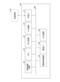
- FIG. 2 is a diagram showing an example of the hardware configuration of the information processing device 40.
- the functions of the information processing device 40 are realized by any hardware or any combination of hardware and software.
- the information processing device 40 includes an external interface 41, an auxiliary storage device 42, a memory device 43, a CPU 44, a high-speed calculation device 45, a communication interface 46, an input device 47, and an output device 48.
- the external interface 41, the auxiliary storage device 42, the memory device 43, the CPU 44, the high-speed calculation device 45, the communication interface 46, the input device 47, and the output device 48 are connected by a bus BS.
- the external interface 41 functions as an interface for reading data from and writing data to the recording medium 41A.
- the recording medium 41A includes general-purpose recording media such as flexible disks, CDs (Compact Discs), DVDs (Digital Versatile Discs), BDs (Blu-ray (registered trademark) Discs), SD memory cards, and USB memories. This allows the information processing device 40 to read various data used in processing through the recording medium 41A, store the data in the auxiliary storage device 42, and install programs that realize various functions.
- the auxiliary storage device 42 stores various installed programs as well as files and data necessary for various processes.
- Examples of the auxiliary storage device 42 include a hard disc drive (HDD), a solid state disc (SSD), an EEPROM, and a flash memory.
- the memory device 43 When an instruction to start a program is received, the memory device 43 reads out and stores the program from the auxiliary storage device 42.
- the memory device 43 includes, for example, a DRAM (Dynamic Random Access Memory) or an SRAM (Static Random Access Memory).
- the CPU 44 executes various programs loaded from the auxiliary storage device 42 to the memory device 43, and realizes various functions related to the information processing device 40 according to the programs.
- the high-speed calculation device 45 works in conjunction with the CPU 44 and performs calculation processing at a higher speed than the CPU 44.
- the high-speed calculation device 45 includes, for example, a GPU (Graphics Processing Unit), an ASIC (Application Specific Integrated Circuit), an FPGA (Field-Programmable Gate Array), etc.
- the high-speed calculation device 45 may be omitted depending on the calculation processing speed required for the information processing device 40.
- the communication interface 46 is used as an interface for connecting to an external device so as to be able to communicate with it. This allows the information processing device 40 to take in the output of the BPF 30 through the communication interface 46. Furthermore, the information processing device 40 can obtain, for example, various data and programs used in processing from an external device through the communication interface 46.
- the communication interface 46 may have multiple types of communication interfaces depending on the communication method between the connected device, etc.
- the input device 47 accepts various inputs from the user of the information processing device 40.
- the input device 47 includes, for example, an input device (hereinafter, "operation input device") that accepts mechanical operation input from a user of the information processing device 40.
- the operation input device includes, for example, a button, a toggle, a lever, a keyboard, a mouse, a touch panel, a touch pad, etc.
- the input device 47 may also include a voice input device capable of receiving voice input from a user of the information processing device 40.
- the voice input device includes, for example, a microphone capable of collecting the voice of the user of the information processing device 40.
- the input device 47 may also include a gesture input device capable of receiving gesture input from a user of the information processing device 40.
- the gesture input device includes, for example, a camera capable of capturing an image of the user's gesture.
- the input device 47 may also include a biometric input device capable of accepting biometric input from a user of the information processing device 40.
- the biometric input device includes, for example, a camera capable of acquiring image data including information related to the user's fingerprint or iris.
- the output device 48 outputs information to the user of the information processing device 40.
- the output device 48 is, for example, a lighting device or a display device that visually outputs information.
- the lighting device is, for example, an indicator lamp.
- the display device is, for example, a liquid crystal display or an organic EL (electroluminescence) display.
- the output device 48 may be a sound output device that outputs auditory information. Examples of the sound output device include a buzzer, an alarm, and a speaker.
- FIG. 3 is a diagram showing a processing flow for setting diagnostic criteria in the information processing device 40. Specifically, FIG. 3 includes FIG. 3A showing pre-processing for setting diagnostic criteria, and FIG. 3B showing main processing for setting diagnostic criteria.
- the pre-processing is performed periodically (e.g., every few hours) after the start of operation of the agitator 52 of the polymerization reaction tank 50.
- the pre-processing may be performed automatically at a predetermined timing, or may be performed manually in response to a request from a user via the input device 47.
- the pre-processing may also be performed at a timing before the process reaction in the polymerization reaction tank 50. This makes it possible to prevent a situation in which a disturbance caused by the process reaction in the polymerization reaction tank 50 is superimposed on the AE signal, and as a result, it is possible to improve the accuracy of the diagnostic criteria set in the main processing described below.
- step S102 the information processing device 40 acquires time series data of the AE signal for the latest predetermined period captured from the BPF 30 from a reception buffer or the like.
- step S102 the information processing device 40 proceeds to step S104.
- step S104 energy calculation process
- the information processing device 40 calculates the AE energy for a predetermined period based on the time series data of the AE signal, and outputs the time series data of the AE energy for the predetermined period.
- the AE energy corresponds to the area of the time waveform of the AE signal, and the information processing device 40 can calculate the AE energy by time integration of the AE signal between the target time and an adjacent time.
- step S104 the information processing device 40 proceeds to steps S106 and S108.
- step S106 the information processing device 40 extracts a component having periodicity (periodic component) from the time series data of the AE energy.
- the information processing device 40 extracts the time series data of the periodic component of the AE energy by calculating a moving average for a certain period immediately prior to each time for the time series data of the AE energy.
- the information processing device 40 may also extract the time series data of the periodic component of the AE energy by using frequency analysis or low-pass filter processing.
- step S108 the information processing device 40 extracts a component (periodicity removed component) from the time series data of the AE energy with the periodic component removed.
- a component periodicity removed component
- the information processing device 40 extracts the time series data of the AE energy with the periodicity removed component by calculating the difference between the target time and the immediately preceding time for the time series data of the AE energy and converting it into a difference series.
- the information processing device 40 may also extract the time series data of the AE energy with the periodicity removed component by calculating the difference between the time series data of the AE energy and the time series data of the periodic component extracted in step S106.
- step S110 the information processing device 40 proceeds to step S110.
- step S110 standard deviation calculation process
- the information processing device 40 calculates a standard deviation ⁇ 1 as an index value related to the variability of the time series data of the periodic component of the AE energy extracted in step S106.
- the information processing device 40 calculates a standard deviation ⁇ 2 as an index value related to the variability of the time series data of the periodicity removed component of the AE energy extracted in step S108.
- step S110 the information processing device 40 proceeds to step S112.
- steps S106 and S108 may be performed in series.
- step S112 the standard deviations ⁇ 1 and ⁇ 2 calculated in step S110 are recorded as record data in the auxiliary storage device 42 together with information indicating the time and information indicating the presence or absence of leakage in the mechanical seal 52D.
- the presence or absence of leakage in the mechanical seal 52D is input by the user through the input device 47, for example.
- the presence or absence of leakage in the mechanical seal 52D may also be automatically determined by applying known image processing techniques, learned models, etc. to images taken by a camera capturing the mechanical seal 52D. This allows the information processing device 40 to retain a record data group equivalent to the history data of the standard deviations ⁇ 1 and ⁇ 2 in the auxiliary storage device 42 through pre-processing that is periodically performed.
- step S112 the information processing device 40 ends the pre-processing.
- the main process is executed after leakage of the contents occurs at the mechanical seal 52D.
- the main process may be executed in response to a request from a user via the input device 47, or, in a case where the presence or absence of leakage at the mechanical seal 52D is automatically determined, may be executed automatically in response to the determination that there is leakage.
- step S114 history data acquisition process
- the information processing device 40 acquires the above-mentioned history data (record data group) from the auxiliary storage device 42.
- step S114 When the processing of step S114 is completed, the information processing device 40 proceeds to step S116.
- step S116 the information processing device 40 sets diagnostic criteria for the standard deviations ⁇ 1 and ⁇ 2 based on the historical data of the standard deviations ⁇ 1 and ⁇ 2. Specifically, the information processing device 40 sets diagnostic criteria for the standard deviations ⁇ 1 and ⁇ 2 based on the distribution of combinations of standard deviations ⁇ 1 and ⁇ 2 corresponding to the situation before leakage occurs in the mechanical seal 52D and the distribution of combinations of standard deviations ⁇ 1 and ⁇ 2 corresponding to the situation after leakage occurs in the mechanical seal 52D. The set diagnostic criteria are registered in the auxiliary storage device 42.
- step S116 When the processing of step S116 is completed, the information processing device 40 ends the main processing.
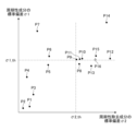
- Fig. 4 is a diagram for explaining an example of a method for setting diagnostic criteria. Specifically, Fig. 4 shows a graph in which the vertical axis represents the standard deviation ⁇ 1 of the periodic component of the AE energy, and the horizontal axis represents the standard deviation ⁇ 2 of the component that has the periodicity removed from the AE energy, and the history data P1 to P16 of the standard deviations ⁇ 1 and ⁇ 2 are plotted.
- historical data P1 represents the oldest historical data
- historical data P16 represents the newest historical data.
- historical data P1 to P15 correspond to the situation before leakage occurred in the mechanical seal 52D
- historical data P16 corresponds to the situation after leakage occurred in the mechanical seal 52D.
- the standard deviation ⁇ 1 of the periodic component of the AE energy converges to a relatively narrow range at a certain level.
- the standard deviation ⁇ 2 of the periodic component removed from the AE energy is relatively larger than in the case of historical data P1 to P7.
- the information processing device 40 can set a diagnostic reference value ⁇ 2_th to indicate that the standard deviation ⁇ 2 of the periodicity-removed component of the AE energy is at a relatively high level.
- the diagnosing entity (for example, the information processing device 140 described below) can diagnose that there is a sign of leakage in the mechanical seal when the standard deviation ⁇ 2 of the periodicity-removed component of the AE energy of the target mechanical seal is relatively large with respect to the diagnostic reference value ⁇ 2_th.
- the standard deviation ⁇ 2 being relatively large with respect to the diagnostic reference value ⁇ 2_th may mean that the standard deviation ⁇ 2 is equal to or larger than the diagnostic reference value ⁇ 2_th, or may mean that the standard deviation ⁇ 2 is larger than the diagnostic reference value ⁇ 2_th.
- the information processing device 40 sets the diagnostic reference value ⁇ 2_th between the upper limit of the standard deviation ⁇ 2 of the historical data P1 to P7 and the lower limit of the standard deviation ⁇ 2 of the historical data P8 to P16. Specifically, the information processing device 40 may set the diagnostic reference value ⁇ 2_th equivalent to a value obtained by subtracting a small margin from the lower limit of the standard deviation ⁇ 2 of the historical data P8 to P16 (the standard deviation ⁇ 2 of the historical data P9).
- the information processing device 40 may also set the diagnostic reference value ⁇ 2_th based on the value of the standard deviation ⁇ 2 of the historical data P8 to P15 corresponding to a timing that goes back a predetermined time from the timing of the first historical data P16 after the occurrence of leakage in the mechanical seal 52D. Specifically, the information processing device 40 may set a diagnostic reference value ⁇ 2_th that corresponds to a value obtained by subtracting a small margin from the standard deviation ⁇ 2 of the historical data at a timing that goes back a predetermined time from the timing of the historical data P16 among the historical data P8 to P15.
- the information processing device 40 may also set a diagnostic reference value ⁇ 1_th that indicates that the standard deviation ⁇ 1 of the periodic component of the AE energy is at a certain level corresponding to the converged state described above.
- a diagnostic reference value ⁇ 1_th that indicates that the standard deviation ⁇ 1 of the periodic component of the AE energy is at a certain level corresponding to the converged state described above. This allows the diagnostic entity to diagnose that there is a sign of leakage in the mechanical seal when the standard deviation ⁇ 2 of the target mechanical seal is relatively large compared to the diagnostic reference value ⁇ 2_th and the standard deviation ⁇ 1 is relatively large compared to the diagnostic reference value ⁇ 1_th. This makes it possible to exclude cases where, for example, the standard deviation ⁇ 2 becomes relatively large compared to the diagnostic reference value ⁇ 2_th while the standard deviation ⁇ 1 is relatively small due to the influence of disturbances, etc. This allows the diagnostic entity to more appropriately diagnose the presence or absence of a sign of leakage in the target mechanical seal.
- the information processing device 40 sets the diagnostic reference value ⁇ 1_th based on the lower limit of the standard deviation ⁇ 1 of the history data P8 to P16 (the standard deviation ⁇ 1 of the history data P13). Specifically, the information processing device 40 may set the diagnostic reference value ⁇ 1_th equivalent to a value obtained by subtracting a small margin from the lower limit of the standard deviation ⁇ 1 of the history data P8 to P16. Also, as shown in FIG. 4, the information processing device 40 may set the diagnostic reference value ⁇ 1_th based on the value of the standard deviation ⁇ 1 of the first history data P16 after leakage occurs in the mechanical seal 52D, among the history data P8 to P16. Specifically, the information processing device 40 may set the diagnostic reference value ⁇ 1_th equivalent to a value obtained by subtracting a predetermined margin from the value of the standard deviation ⁇ 1 of the history data P16.
- the information processing device 40 can set the diagnostic reference value ⁇ 1_th and the diagnostic reference value ⁇ 2_th for the standard deviation ⁇ 1 of the periodic component of the AE energy time series data and the standard deviation ⁇ 2 of the periodicity removed component, respectively.
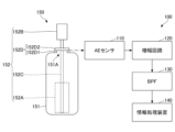
- FIG. 5 shows an example of a monitoring system 100.
- the monitoring system 100 includes an acoustic emission (AE) sensor 110, an amplifier circuit 120, a bandpass filter (BPF) 130, and an information processing device 140.
- AE acoustic emission
- BPF bandpass filter
- the monitoring system 100 monitors the condition of the shaft-sealing mechanical seal 152D that is installed in the polymerization reaction vessel 150 to be monitored. Specifically, the monitoring system 100 monitors the condition of the mechanical seal 152D by diagnosing whether there are any signs of leakage in the mechanical seal 152D.
- the polymerization reaction tank 150 is a polymerization reaction tank with the same specifications as the polymerization reaction tank 50 described above. Like the polymerization reaction tank 50 described above, the polymerization reaction tank 150 includes a tank body 151 and an agitator 152.
- the tank body 151 has the same function and structure as the tank body 51 described above, and a through hole 151A is provided in the upper part of the tank body 151, penetrating between the inside and the outside.
- the agitator 152 has the same function and structure as the agitator 52 described above, and includes a rotor 152A, a motor 152B, a rotor shaft 152C, and a mechanical seal 152D.
- the mechanical seal 152D includes a stationary ring 152D1 and a rotating ring 152D2, similar to the mechanical seal 52D described above.
- the functions and structures of the rotor 152A, motor 152B, rotor shaft 152C, and mechanical seal 152D are similar to those of the rotor 52A, motor 52B, rotor shaft 52C, and mechanical seal 52D described above, and therefore will not be described in detail.
- the AE sensor 110 measures the AE of the shaft-sealing mechanical seal 152D mounted in the polymerization reaction tank 150 being monitored, and outputs a signal (AE signal) that represents the measurement result.
- the amplifier circuit 120 has the same function as the amplifier circuit 20 described above, and amplifies and outputs the AE signal output from the AE sensor 110.
- the output signal of the amplifier circuit 120 is input to the BPF 130.
- BPF 130 has the same function as BPF 30 described above, and passes and outputs only components of a predetermined frequency band from the amplified AE signal input from amplifier circuit 120. This allows BPF 30 to output an AE signal of the predetermined frequency band.
- the predetermined frequency band is a frequency band in which the state of mechanical seal 152D can produce a characteristic AE.
- the predetermined frequency band is, for example, 30 kHz to 200 kHz, as in the case of BPF 30 described above.
- the output signal of BPF 130 is input to information processing device 140.
- the information processing device 140 diagnoses whether there are any signs of leakage in the mechanical seal 152D based on the AE signal for a predetermined period input from the BPF 130 and the diagnostic criteria set by the information processing device 40 described above.
- the AE signal used to diagnose whether there are signs of leakage in the mechanical seal 152D is preferably an AE signal recorded, for example, at a timing before the process reaction in the polymerization reaction tank 150. This makes it possible to prevent a situation in which disturbances caused by the process reaction are superimposed on the AE signal, and as a result, the information processing device 140 can improve the accuracy of the diagnosis.
- the information processing device 140 is, for example, a server device with relatively high processing capabilities, similar to the above-mentioned information processing device 40. Also, similar to the information processing device 40, the information processing device 140 may be a terminal device with lower processing capabilities than the server device, so long as it has the capability to execute the necessary processes.
- the hardware configuration of the information processing device 140 may be the same as that of the information processing device 40 described above. Therefore, illustration and description of the hardware configuration of the information processing device 140 will be omitted.
- FIG. 6 shows an example of a process flow for monitoring the presence or absence of signs of leakage in the mechanical seal 152D of the information processing device 140.
- the process flow of FIG. 6 is executed automatically at each predetermined processing cycle, for example.
- the process flow of FIG. 6 may also be executed manually in response to a request from a user via an input device.
- the process flow of FIG. 6 may also be executed at a timing before the process reaction in the polymerization reaction tank 150. This makes it possible to prevent a situation in which disturbances caused by the process reaction in the polymerization reaction tank 150 are superimposed on the AE signal, and as a result, the information processing device 140 can improve the accuracy of diagnosing whether there are signs of leakage in the mechanical seal 152D.
- steps S202, S204, S206, S208, and S210 are the same as steps S102, S104, S106, S108, and S110 performed by the information processing device 40 described above, and therefore detailed explanations may be omitted.
- step S202 the information processing device 140 acquires the time series data of the AE signal for the latest predetermined period captured by the BPF 130 from a reception buffer or the like.
- step S202 When the processing of step S202 is completed, the information processing device 140 proceeds to step S204.
- step S204 energy calculation process
- the information processing device 140 calculates the AE energy for a predetermined period based on the time series data of the AE signal, and outputs the time series data of the AE energy for the predetermined period.
- step S204 the information processing device 140 proceeds to steps S206 and S208.
- step S206 the information processing device 140 extracts periodic components from the time series data of the AE energy.
- step S208 the information processing device 140 extracts the periodicity removal component from the time series data of the AE energy.
- step S210 the information processing device 140 proceeds to step S210.
- step S210 standard deviation calculation process
- the information processing device 140 calculates the standard deviation ⁇ 1 of the time series data of the periodic component of the AE energy extracted in step S206.
- the information processing device 140 calculates the standard deviation ⁇ 2 of the time series data of the periodicity removed component of the AE energy extracted in step S208.
- step S210 the information processing device 140 proceeds to step S212.
- steps S206 and S208 may be performed in series.
- step S212 the information processing device 140 diagnoses whether there is a sign of leakage in the mechanical seal 152D based on the standard deviations ⁇ 1 and ⁇ 2 calculated in step S210. Specifically, the information processing device 140 diagnoses whether there is a sign of leakage in the mechanical seal 152D based on the standard deviations ⁇ 1 and ⁇ 2 calculated in step S210 and the diagnostic reference values ⁇ 1_th and ⁇ 2_th set by the information processing device 40.
- the information processing device 140 diagnoses that there is a sign of leakage in the mechanical seal 152D when the standard deviation ⁇ 1 is relatively large compared to the diagnostic reference value ⁇ 1_th and the standard deviation ⁇ 2 is relatively large compared to the diagnostic reference value ⁇ 2_th. On the other hand, the information processing device 140 diagnoses that there is no sign of leakage in the mechanical seal 152D in other cases.
- step S212 the information processing device 140 proceeds to step S214.
- step S214 the information processing device 140 notifies the user of the diagnosis result in step S212.
- the information processing device 140 notifies the user of the diagnosis result by a visual or audible method through an output device such as its own display device or sound output device.
- the information processing device 140 may also notify the user of the diagnosis result by transmitting the diagnosis result to a terminal device (user terminal) held by the user through a communication interface.
- the information processing device 140 may also notify the user of the diagnosis result through email, SNS (Social Networking Service), or the like. This allows the user of the monitoring system 100 to understand the diagnosis result of whether there is a sign of leakage in the mechanical seal 152D.
- SNS Social Networking Service
- the user when the user understands the diagnosis result that there is a sign of leakage in the mechanical seal 152D, the user can order parts for replacement of the mechanical seal 152D and adjust the timing of replacement according to the operating status of the polymerization reaction tank 150, etc.
- step S214 the information processing device 140 ends the processing flow.
- the information processing device 140 can diagnose whether there are signs of leakage in the mechanical seal 152D by comparing the standard deviations ⁇ 1, ⁇ 2 of the time series data of the periodic component and periodicity removal component of the AE energy of the mechanical seal 152D with the diagnostic reference values ⁇ 1_th, ⁇ 2_th.
- Fig. 7 is a diagram showing a specific example of the time-dependent change in the history of standard deviations ⁇ 1 and ⁇ 2 of the time-series data of the periodic component and periodicity removal component of the acoustic emission (AE) energy of the mechanical seal 152D.
- Fig. 7 includes Figs. 7A and 7B, which respectively show the time-dependent change in the history of standard deviations ⁇ 1 and ⁇ 2 of the time-series data of the periodic component and periodicity removal component of the AE energy until leakage occurs in different polymerization reaction vessels 150.
- Fig. 7A and 7B which respectively show the time-dependent change in the history of standard deviations ⁇ 1 and ⁇ 2 of the time-series data of the periodic component and periodicity removal component of the AE energy until leakage occurs in different polymerization reaction vessels 150.
- 7A includes a graph 701 of the time-dependent change in the history of standard deviation ⁇ 2 of the time-series data of the periodicity removal component of the AE energy of the mechanical seal 152D, and a graph 702 of the time-dependent change in the history of standard deviation ⁇ 1 of the time-series data of the periodic component of the AE energy of the mechanical seal 152D.
- FIG. 7B includes a graph 703 of a time-varying history of the standard deviation ⁇ 2 of the time-series data of the periodicity-removed component of the AE energy of the mechanical seal 152D, and a graph 704 of a time-varying history of the standard deviation ⁇ 1 of the time-series data of the periodicity-removed component of the AE energy of the mechanical seal 152D.
- FIG. 8 is a diagram for explaining a second example of a method for monitoring the presence or absence of a sign of leakage in the mechanical seal 152D. Specifically, FIG.
- FIG. 8 is a diagram that diagrammatically illustrates a quadratic curve 801 that represents the tendency of the time-varying history of the standard deviation ⁇ 1 of the time-series data of the periodicity-removed component of the AE energy of the mechanical seal 152D until the mechanical seal 152D fails, and a quadratic curve 802 that represents the tendency of the time-varying history of the standard deviation ⁇ 2 of the time-series data of the periodicity-removed component until the mechanical seal 152D fails.
- the solid lines in graphs 701 to 704 are quadratic curves that approximate the time changes in the historical data of standard deviation ⁇ 1 or standard deviation ⁇ 2, respectively.
- the information processing device 140 can diagnose that there is an indication of leakage from the mechanical seal 152D.
- the historical data for standard deviation ⁇ 2 takes on a relatively small value, and continues to show a relatively small change over time, after which it transitions to a state in which the increase over time is relatively large. It can also be seen that the history of standard deviation ⁇ 2 transitions from a state in which the increase over time is relatively large to a peak of a relatively large value, and then transitions to a state in which the decrease over time is relatively large, and after this trend continues, it reaches a relatively small value, leading to leakage from mechanical seal 152D.
- the information processing device 140 can diagnose that there is an indication of leakage from the mechanical seal 152D.
- the information processing device 140 may diagnose that there are signs of leakage in the mechanical seal 152D when the history of the standard deviation ⁇ 1 transitions from state 801A, in which a continuing increasing trend over time, to state 801B, in which a continuing decreasing trend over time, and then the history of the standard deviation ⁇ 2 transitions from state 802A, in which a relatively small change over time tends to occur, to state 802B, in which a relatively large increase over time tends to occur.
- This allows the information processing device 140 to more reliably diagnose the presence or absence of signs of leakage in the mechanical seal 152D.
- steps S202, S204, S206, S208, and S210 are the same as those in the first example of the monitoring method described above, so a description thereof will be omitted.
- step S210 the information processing device 140 proceeds to step S212.
- step S212 the information processing device 140 diagnoses whether there are any signs of leakage from the mechanical seal 152D based on the historical data of the standard deviations including the standard deviations ⁇ 1 and ⁇ 2 calculated in this step S210. Specifically, the information processing device 140 determines whether the first monitoring condition has already been met for the historical data of the standard deviation ⁇ 1 in the past process, and whether the second monitoring condition is met for the historical data of the standard deviation ⁇ 2 in the current process.
- the first monitoring condition is a condition indicating that the standard deviation history has transitioned from a state in which a continuing increasing trend over time continues to a state in which a continuing decreasing trend over time continues.
- the second monitoring condition is a condition indicating that the standard deviation history of ⁇ 2 has transitioned from a state in which a relatively small tendency for change over time continues to a state in which a relatively large tendency for increase over time continues.
- the information processing device 140 judges whether the first monitoring condition is satisfied. If the first monitoring condition is satisfied, the information processing device 140 sets the flag F1, which indicates that the first monitoring condition has been satisfied, from "0" (not satisfied) to "1" (satisfied), and if the first monitoring condition is not satisfied, the flag F1 is maintained at the initial value of "0". Then, the information processing device 140 diagnoses that there is no sign of leakage in the mechanical seal 152D. On the other hand, if the first monitoring condition was satisfied in the past processing, that is, if the flag F1 is "1", the information processing device 140 judges whether the second monitoring condition is satisfied.
- the information processing device 140 diagnoses that there is a sign of leakage in the mechanical seal 152D, and if the second monitoring condition is not satisfied, the information processing device 140 diagnoses that there is no sign of leakage in the mechanical seal 152D.
- the first monitoring condition is, for example, that an approximation curve (e.g., a quadratic curve) representing the time change of the history of the standard deviation ⁇ 1 continues to decrease in the most recent specified period (first period) and continues to increase in the specified period (second period) before the first period.
- an approximation curve e.g., a quadratic curve
- the information processing device 140 performs, for example, a quadratic curve approximation on the data of the history of the standard deviation ⁇ 1 to obtain the approximation curve.
- the second monitoring condition is, for example, that the latest value of an approximation curve (e.g., a quadratic curve) representing the time change of the history of the standard deviation ⁇ 2 is equal to or greater than a predetermined threshold TH1, and the average value of the entire past period or the most recent past predetermined period is equal to or less than a threshold TH2 ( ⁇ TH1).
- the information processing device 140 performs, for example, a quadratic curve approximation of the data of the history of the standard deviation ⁇ 2 to obtain the approximation curve.
- step S212 When the processing of step S212 is completed, the information processing device 140 proceeds to step S214.
- step S214 The processing content of step S214 is the same as in the first example of the monitoring method described above, so a description thereof will be omitted.
- step S214 the information processing device 140 ends the processing flow.
- the information processing device 140 can diagnose whether there are signs of leakage in the mechanical seal 152D based on the tendency of time changes in the standard deviations ⁇ 1 and ⁇ 2 of the time series data of the periodic component and periodicity removal component of the AE energy of the mechanical seal 152D.
- the diagnostic criteria may be set using the measurement signals (AE signals) of the AE sensors 10 corresponding to each of the multiple polymerization reaction vessels 50.
- diagnostic criteria may be set using a polymerization reactor of the same specifications that is actually used in a factory or the like for the manufacture of products, instead of or in addition to the polymerization reactor 50 as an experimental machine.
- the diagnostic criteria setting system 1 instead of a polymerization reactor equipped with a mechanical seal, the diagnostic criteria may be set using an experimental device that simulates a mechanical seal installed in a polymerization reactor.
- the diagnostic criteria setting system 1 may set a common diagnostic criterion corresponding to the mechanical seals installed in multiple polymerization reactors with different specifications.
- the information processing device 40 may set the diagnostic criterion using the AE signals of the mechanical seals corresponding to all of the target polymerization reactors, or may set the diagnostic criterion using the AE signals of the mechanical seals corresponding to some of the target polymerization reactors.
- the information processing device 40 may set a diagnostic criterion for each group of polymerization reactors classified according to the use conditions of the mechanical seal.
- multiple polymerization reactors for which the diagnostic criterion can be shared are grouped into one group, and a common diagnostic criterion is set for the multiple polymerization reactors included in one group.
- the group classified according to the use conditions of the mechanical seal is, for example, a group classified according to the material of the rotating shaft of the agitator of the polymerization reactor.
- Groups categorized by the material of the rotating shaft of the agitator of the polymerization reaction tank include, for example, a group in which the rotating shaft of the agitator is made up only of machined metal parts, and a group that includes baked parts such as glass and resin.
- the diagnostic criteria setting system 1 may set diagnostic criteria for diagnosing the presence or absence of signs of leakage in a mechanical seal installed in equipment other than the polymerization reaction tank.
- the diagnostic criteria setting system 1 may set diagnostic criteria for diagnosing the presence or absence of signs of failure in an object other than a mechanical seal.
- the information processing device 40 may set diagnostic criteria for diagnosing the presence or absence of signs of failure in a bearing based on the AE signal of a bearing mounted on a specified rotating machine.
- the diagnostic criterion setting system 1 only one of the diagnostic criterion values ⁇ 1_th and ⁇ 2_th may be set, and the setting of the other diagnostic criterion value may be omitted.
- the information processing device 140 uses one of the set diagnostic criterion values to diagnose the presence or absence of a sign of leakage in the mechanical seal 152D based on only one of the time series signals of the periodic component and the periodicity removal component of the AE energy of the mechanical seal 152D. Also, in this case, one of the processes of steps S106 and S108 in FIG. 3 and one of the processes of steps S206 and S208 in FIG. 6 are omitted.
- the information processing device 40 may generate a trained model based on historical data of at least one of the standard deviations ⁇ 1 and ⁇ 2, instead of setting a diagnostic criterion.
- the trained model corresponds to a classifier that classifies the presence or absence of signs of failure of the object based on at least one of the standard deviation ⁇ 1 of the periodic component of the energy of the AE of the object and the standard deviation ⁇ 2 of the periodicity removed component.
- a sign of leakage in the mechanical seal 152D may be diagnosed based on only one of the standard deviations ⁇ 1 and ⁇ 2. In this case, one of the processes in steps S206 and S208 in FIG. 6 is omitted.
- the information processing device 40 and the information processing device 140 may be the same information processing device.
- the diagnostic criteria may be set and the state of the object may be monitored based on the set diagnostic criteria by a common information processing device.
- At least one of the amplifier circuit 20 and the BPF 30 may be omitted in the diagnostic criteria setting system 1.
- at least one of the amplifier circuit 120 and the BPF 130 may be omitted in the monitoring system 100.
- the information processing device acquires a time series measurement signal of the acoustic emission (AE) of the object.
- the information processing device is, for example, the above-mentioned information processing device 40 or information processing device 140.
- the object is, for example, the above-mentioned mechanical seal 52D or mechanical seal 152D.
- the information processing device calculates the AE energy of the object based on the measurement signal.
- the information processing device also extracts a first component time series signal obtained by removing a second component having periodicity from the energy time series signal, or a time series signal of the second component.
- the first component is, for example, the above-mentioned periodicity-removed component.
- the second component is, for example, the above-mentioned periodic component.
- the information processing device then calculates an index value related to the variability of the first component time series signal or the second component time series signal.
- the index value related to the variability of the first component time series signal is, for example, the above-mentioned standard deviation ⁇ 2.
- the index value for the variability of the time series signal of the second component is, for example, the standard deviation ⁇ 1 described above.
- the information processing method includes an acquisition step, an energy calculation step, a first extraction step, and a variation calculation step.
- the acquisition step is, for example, step S102 or step S202 described above.
- the energy calculation step is, for example, step S104 or step S204 described above.
- the first extraction step is step S108, step S208, or step S206 described above.
- the variation calculation step is step S110 or step S210 described above.
- the information processing device acquires a time series measurement signal of the AE of the object.
- the energy calculation step the information processing device calculates the energy of the AE of the object based on the measurement signal.
- the information processing device extracts a time series signal of the first component by removing a second component having periodicity from the time series signal of the energy, or a time series signal of the second component. Then, in the variability calculation step, the information processing device calculates an index value related to the variability of the time series signal of the first component or the time series signal of the second component.
- the information processing device can calculate an index value relating to the variance in the time series signal of the first component of the AE energy of the object, or the time series signal of the second component. Therefore, for example, the information processing device can relatively easily monitor the state of the object based on the index value. Also, for example, the information processing device can set a reference value for the index value, and more easily monitor the state of the object based on a comparison of the index value with the reference value.
- the information processing method may include a second extraction step.
- the second extraction step is, for example, the above-mentioned step S106 or step S206.
- a time series signal of the first component may be extracted.
- the information processing device may extract a time series signal of the second component from the time series signal of the energy.
- an index value related to the variability of both the time series signal of the first component and the time series signal of the second component may be calculated.
- the information processing device can calculate index values relating to the variability in the time series signals of both the first and second components of the AE energy of the object. Therefore, for example, the information processing device can relatively easily monitor the state of the object based on both index values. Also, for example, the information processing device can set reference values for each of both index values, thereby more easily monitoring the state of the object based on a comparison between the index values and the reference values.
- the information processing method may include a diagnosis step in which the information processing device diagnoses the presence or absence of signs of a malfunction of the object mounted on a specified device based on the tendency of time-varying changes in the history of the index value related to the variance of the time-series signal of the first component or the time-series signal of the second component.
- the information processing device can easily monitor the presence or absence of signs of failure in an object mounted on a specified device based on an index value relating to the variance in the time series signal of the first component or the time series signal of the second component of the object's AE energy.
- the information processing method may include a diagnostic step in which the information processing device diagnoses the presence or absence of signs of a malfunction of the object mounted on a specified device based on the trends of time-varying changes in both the time-series signal of the first component and the history of the index value related to the variance of the time-series signal of the second component.
- the information processing device can easily monitor the presence or absence of signs of failure in an object mounted on a specified device based on index values relating to the variability in both the time series signal of the first component of the object's AE energy and the time series signal of the second component.
- the diagnosis step may diagnose that there is a sign of a malfunction of the object mounted on a specified device when the history of the index value relating to the variability of the time series signal of the second component transitions from an increasing trend over time to a decreasing trend over time.
- the diagnosis step may diagnose that there is a sign of a failure of the object mounted on a specified device when the history of the index value relating to the variance of the time series signal of the first component transitions from a state in which the change over time is relatively small to a state in which the change over time is relatively large.
- a seventh aspect of this embodiment assuming the fourth aspect described above, in the diagnosis step, if the history of the index value related to the variance of the time series signal of the second component transitions from an increasing trend over time to a decreasing trend over time, and then the history of the index value related to the variance of the time series signal of the first component transitions from a state in which the change over time is relatively small to a state in which the increase over time is relatively large, it may be diagnosed that there is a sign of a failure of the object mounted on a specified device.
- the information processing device can easily monitor the presence or absence of signs of failure in an object mounted on a specified device based on index values relating to the variability in both the time series signal of the first component of the object's AE energy and the time series signal of the second component.
- the information processing method may include a setting step.
- the setting step is, for example, step S116 described above.
- the information processing device sets a reference value for determining whether or not there is a sign of a failure of the object mounted on a specified device.
- the information processing device is, for example, the information processing device 40 described above.
- the specified device is, for example, the polymerization reaction tank 50 described above.
- the object is, for example, the mechanical seal 52D described above.
- a plurality of measurement signals of the AE of the object mounted on the specified device may be acquired, the plurality of measurement signals including both the measurement signal in a situation before the occurrence of a failure of the object and the measurement signal in a situation after the occurrence of a failure of the object.
- the energy corresponding to each of the plurality of measurement signals acquired in the acquisition step may be calculated.
- the first component may be extracted from a time series signal of the energy corresponding to each of the plurality of measurement signals.
- the index value for the variation of the time series signal of the first component corresponding to each of the multiple measurement signals may be calculated.
- a first reference value for the index value for the variation of the time series signal of the first component may be set based on the distribution of the index value for the variation of the time series signal of the first component corresponding to the measurement signal in a situation before the occurrence of a failure of the object and the distribution of the index value for the variation of the time series signal of the first component corresponding to the measurement signal in a situation after the occurrence of a failure of the object, among the index values for the variation of the time series signal of the first component corresponding to each of the multiple measurement signals.
- the first reference value is, for example, the above-mentioned diagnostic reference value ⁇ 2_th.
- the information processing device can set a first reference value for an index value relating to the variability in the time series signal of the first component of the AE energy in order to determine the presence or absence of signs of failure of the object. Therefore, the information processing device can realize monitoring of the presence or absence of signs of failure of the object based on a comparison of the index value relating to the variability in the time series signal of the first component of the AE energy with the first reference value.
- the information processing device may include a setting step. Specifically, in the setting step, a reference value for determining whether or not there is a sign of a failure of the object mounted on a specified device may be set. In addition, in the acquisition step, a plurality of measurement signals of the AE of the object mounted on the specified device may be acquired, the measurement signals including both the measurement signal in a state before the occurrence of a failure of the object and the measurement signal in a state after the occurrence of a failure of the object. In addition, in the energy calculation step, the energy corresponding to each of the plurality of measurement signals acquired in the acquisition step may be calculated.
- the first component may be extracted from the time series signal of the energy corresponding to each of the plurality of measurement signals.
- the time series signal of the second component obtained by removing the first component from the time series signal of the energy corresponding to each of the plurality of measurement signals may be extracted.
- the variation calculation step may calculate the index value related to the variation of the time-series signal of the first component corresponding to each of the plurality of measurement signals, and calculate the index value related to the variation of the time-series signal of the second component corresponding to each of the plurality of measurement signals.
- the setting step may set a first reference value for the index value related to the variation of the time-series signal of the first component and a second reference value for the index value related to the variation of the time-series signal of the second component based on a distribution of combinations of the index values related to the variation of the time-series signal of both the first component and the second component corresponding to the measurement signals in a situation before the occurrence of a failure of the object and a distribution of combinations of the index values of the time-series signal of the first component and the second component corresponding to the measurement signals in a situation after the occurrence of a failure of the object, among combinations of the index values related to the variation of the time-series signal of both the first component and the second component corresponding to each of the plurality of measurement signals.
- the first reference value and the second reference value are, for example, the diagnostic reference value ⁇ 2_th and the diagnostic reference value ⁇ 1_th described above, respectively.
- the information processing device can thus set a first reference value and a second reference value for determining whether or not there are signs of failure in the object, the first reference value and the second reference value being for index values relating to the variability in the time series signals of the first component and the second component of the AE energy.
- the information processing device can realize monitoring of the presence or absence of signs of failure in the object based on a comparison of the index values relating to the variability in the time series signals of the first component and the second component of the AE energy with the first reference value and the second reference value, respectively.
- the multiple measurement signals may be a collection of measurement signals at different timings for the same specified device.
- the first reference value may be set based on the index value related to the signal variability of the first component corresponding to the measurement signal at a timing that is a predetermined time prior to the timing of the measurement signal that was first recorded after the occurrence of a failure of the object.
- the information processing device can appropriately set a first reference value for determining whether or not there are signs of an occurrence of a failure in the object, based on the change over time in the index value relating to the variance in the time series signal of the first component of the AE energy of the object for the same specified device.
- the multiple measurement signals may be a collection of measurement signals at different timings for the same specified device.
- the first reference value may be set based on the index value related to the variability of the signal of the first component corresponding to the measurement signal at a timing a predetermined time back from the timing of the measurement signal first recorded after the occurrence of a failure of the object
- the second reference value may be set based on the index value related to the variability of the signal of the second component corresponding to the measurement signal first recorded after the occurrence of a failure of the object.
- the information processing device can appropriately set a first reference value and a second reference value for determining whether or not there are signs of a failure occurring in the object, based on the change over time in the index values relating to the variability in the time series signals of the first and second components of the AE energy of the object for the same specified device.
- a reference value for determining whether or not there is a sign of a failure of the object may be set for each group related to the plurality of predetermined devices that are classified according to the use conditions of the object.
- the information processing device can set a reference value for each group of multiple specified devices that matches the usage conditions. Therefore, the information processing device can improve the accuracy of determining whether or not there are signs of failure in the target object for each group of multiple specified devices.
- the specified device may be a polymerization reaction tank.
- the object may be a mechanical seal for sealing a shaft.
- the acquisition step may acquire the measurement signal recorded at a timing before the process reaction in the polymerization reaction tank.
Landscapes
- Physics & Mathematics (AREA)
- General Physics & Mathematics (AREA)
- Investigating Or Analyzing Materials By The Use Of Ultrasonic Waves (AREA)
- Testing Of Devices, Machine Parts, Or Other Structures Thereof (AREA)
Abstract
Description
情報処理装置が、対象物のアコースティックエミッションの時系列の測定信号を取得する取得ステップと、
情報処理装置が、前記測定信号に基づき、前記対象物のアコースティックエミッションのエネルギを算出するエネルギ算出ステップと、
情報処理装置が、前記エネルギの時系列の信号から周期性を有する第2の成分を除去した、第1の成分の時系列の信号、又は前記第2の成分の時系列の信号を抽出する第1の抽出ステップと、
情報処理装置が、前記第1の成分の時系列の信号、又は前記第2の成分の時系列の信号のばらつきに関する指標値を算出するばらつき算出ステップと、を含む、
情報処理方法が提供される。
情報処理装置が、前記エネルギの時系列の信号から前記第2の成分の時系列の信号を抽出する第2の抽出ステップを含み、
前記第1の抽出ステップでは、前記第1の成分の時系列の信号を抽出し、
前記ばらつき算出ステップでは、前記第1の成分の時系列の信号、及び前記第2の成分の時系列の信号の双方のばらつきに関する指標値を算出してもよい。
情報処理装置が、前記第1の成分の時系列の信号、又は前記第2の成分の時系列の信号のばらつきに関する前記指標値の履歴の時間変化の傾向に基づき、所定の機器に搭載される前記対象物の故障の兆候の有無を診断する診断ステップを含んでもよい。
情報処理装置が、前記第1の成分の時系列の信号、及び前記第2の成分の時系列の信号のばらつきに関する前記指標値の履歴の双方の時間変化の傾向に基づき、所定の機器に搭載される前記対象物の故障の兆候の有無を診断する診断ステップを含んでもよい。
前記診断ステップでは、前記第2の成分の時系列の信号のばらつきに関する前記指標値の履歴が時間経過に対する増加傾向から時間経過に対する減少傾向に移行する場合に、所定の機器に搭載される前記対象物の故障の兆候があると診断してもよい。
前記診断ステップでは、前記第1の成分の時系列の信号のばらつきに関する前記指標値の履歴が時間経過に対する変化が相対的に小さい状態から時間経過に対する変化が相対的に大きい状態に移行する場合に、所定の機器に搭載される前記対象物の故障の兆候があると診断してもよい。
前記診断ステップでは、前記第2の成分の時系列の信号のばらつきに関する前記指標値の履歴が時間経過に対する増加傾向から時間経過に対する減少傾向に移行し、その後、前記第1の成分の時系列の信号のばらつきに関する前記指標値の履歴が時間経過に対する変化が相対的に小さい状態から時間経過に対する増加が相対的に大きい状態に移行する場合に、所定の機器に搭載される前記対象物の故障の兆候があると診断してもよい。
情報処理装置が、所定の機器に搭載される前記対象物の故障の兆候の有無を判断するための基準値を設定する設定ステップを含み、
前記取得ステップでは、前記所定の機器に搭載される前記対象物のアコースティックエミッションの複数の前記測定信号であって、前記対象物の故障の発生前の状況での前記測定信号及び前記対象物の故障の発生後の状況での前記測定信号の双方を含む複数の前記測定信号を取得し、
前記エネルギ算出ステップでは、前記取得ステップで取得される、複数の前記測定信号のそれぞれに対応する前記エネルギを算出し、
前記第1の抽出ステップでは、複数の前記測定信号のそれぞれに対応する前記エネルギの時系列の信号から前記第1の成分を抽出し、
前記ばらつき算出ステップでは、複数の前記測定信号のそれぞれに対応する前記第1の成分の時系列の信号のばらつきに関する前記指標値を算出し、
前記設定ステップでは、複数の前記測定信号のそれぞれに対応する前記第1の成分の時系列の信号のばらつきに関する前記指標値のうち、前記対象物の故障の発生前の状況での前記測定信号に対応する前記第1の成分の時系列の信号のばらつきに関する前記指標値の分布と、前記対象物の故障の発生後の状況での前記測定信号に対応する前記第1の成分の時系列の信号のばらつきに関する前記指標値の分布とに基づき、前記第1の成分の時系列の信号のばらつきに関する前記指標値に対する第1の基準値を設定してもよい。
情報処理装置が、所定の機器に搭載される前記対象物の故障の兆候の有無を判断するための基準値を設定する設定ステップを含み、
前記取得ステップでは、前記所定の機器に搭載される前記対象物のアコースティックエミッションの複数の前記測定信号であって、前記対象物の故障の発生前の状況での前記測定信号及び前記対象物の故障の発生後の状況での前記測定信号の双方を含む複数の前記測定信号を取得し、
前記エネルギ算出ステップでは、前記取得ステップで取得される、複数の前記測定信号のそれぞれに対応する前記エネルギを算出し、
前記第1の抽出ステップでは、複数の前記測定信号のそれぞれに対応する前記エネルギの時系列の信号から前記第1の成分を抽出し、
前記第2の抽出ステップでは、複数の前記測定信号のそれぞれに対応する前記エネルギの時系列の信号から前記第1の成分を除去した前記第2の成分の時系列の信号を抽出し、
前記ばらつき算出ステップでは、複数の前記測定信号のそれぞれに対応する前記第1の成分の時系列の信号のばらつきに関する前記指標値を算出し、複数の前記測定信号のそれぞれに対応する前記第2の成分のばらつきに関する前記指標値を算出し、
前記設定ステップでは、複数の前記測定信号のそれぞれに対応する前記第1の成分及び前記第2の成分の双方の時系列の信号の前記指標値の組み合わせのうち、前記対象物の故障の発生前の状況での前記測定信号に対応する前記第1の成分及び前記第2の成分の双方の時系列の信号のばらつきに関する前記指標値の組み合わせの分布と、前記対象物の故障の発生後の状況での前記測定信号に対応する前記第1の成分及び前記第2の成分の時系列の信号のばらつきに関する前記指標値の分布とに基づき、前記第1の成分の時系列の信号のばらつきに関する前記指標値に対する第1の基準値、及び前記第2の成分の時系列の信号のばらつきに関する前記指標値に対する第2の基準値を設定してもよい。
複数の前記測定信号は、同一の前記所定の機器についての異なるタイミングでの前記測定信号の集まりであり、
前記設定ステップでは、前記対象物の故障の発生後の最初に記録された前記測定信号のタイミングから所定時間だけ遡ったタイミングでの前記測定信号に対応する前記第1の成分の信号の前記指標値に基づき、前記第1の基準値を設定してもよい。
複数の前記測定信号は、同一の前記所定の機器についての異なるタイミングでの前記測定信号の集まりであり、
前記設定ステップでは、前記対象物の故障の発生後の最初に記録された前記測定信号のタイミングから所定時間だけ遡ったタイミングでの前記測定信号に対応する前記第1の成分の信号のばらつきに関する前記指標値に基づき、前記第1の基準値を設定し、前記対象物の故障の発生後の最初に記録された前記測定信号に対応する前記第2の成分の信号のばらつきに関する前記指標値に基づき、前記第2の基準値を設定してもよい。
前記設定ステップでは、前記対象物の使用条件に応じて区分される、複数の前記所定の機器に関するグループごとに、前記対象物の故障の兆候の有無を判断するための基準値を設定してもよい。
前記所定の機器は、重合反応槽であり、
前記対象物は、軸封用のメカニカルシールであってもよい。
前記取得ステップでは、前記重合反応槽におけるプロセス反応前のタイミングで記録された前記測定信号を取得してもよい。
対象物のアコースティックエミッションの時系列の測定信号を取得し、
前記測定信号に基づき、アコースティックエミッションのエネルギを算出し、
前記エネルギの時系列の信号から周期性を有する第2の成分を除去した第1の成分の時系列の信号、又は前記第2の成分の時系列の信号を抽出し、
前記第1の成分の時系列の信号、又は前記第2の成分の時系列の信号のばらつきに関する指標値を算出する、
情報処理装置が提供される。
図1を参照して、本実施形態に関する診断基準設定システム1の概要について説明する。
次に、図2を参照して、情報処理装置40のハードウェア構成について説明する。
次に、図3、図4を参照して、診断基準の設定方法について説明する。
事前処理は、例えば、重合反応槽50の撹拌機52の運転開始後、定期的に(例えば、数時間ごとに)実施される。事前処理は、所定のタイミングの到来に応じて、自動的に実施されてもよいし、入力装置47を通じたユーザからの要求に応じて、手動で実施されてもよい。また、事前処理は、重合反応槽50におけるプロセス反応前のタイミングで実施されてもよい。これにより、重合反応槽50におけるプロセス反応に起因する外乱がAE信号に重畳するような事態を防止することができ、その結果、後述のメイン処理で設定される診断基準の精度を向上させることができる。
メイン処理は、メカニカルシール52Dにおける内容物の漏洩の発生後に実行される。メイン処理は、入力装置47を通じたユーザからの要求に応じて実施されてもよいし、メカニカルシール52Dにおける漏洩の有無が自動的に判断される場合、漏洩ありの判断に応じて、自動的に実施されてもよい。
図4は、診断基準の設定方法の一例を説明する図である。具体的には、図4は、縦軸をAEのエネルギの周期性成分の標準偏差σ1とし、横軸をAEのエネルギの周期性除去成分の標準偏差σ2として、標準偏差σ1、σ2の履歴データP1~P16をプロットしたグラフを表している。
次に、図5を参照して、監視システム100の概要について説明する。
次に、図6を参照して、メカニカルシール152Dの状態の監視方法の第1例について説明する。
次に、図6に加えて、図7、図8を参照して、メカニカルシール152Dの状態の監視方法の第2例について説明する。
図7は、メカニカルシール152Dのアコースティックエミッション(AE)のエネルギの周期性成分、及び周期性除去成分のそれぞれの時系列データの標準偏差σ1、σ2の履歴の時間変化の具体例を示す図である。図7は、それぞれ、互い異なる重合反応槽150におけるメカニカルシール152Dの漏洩が発生するまでのAEのエネルギの周期性成分、及び周期性除去成分のそれぞれの時系列データの標準偏差σ1、σ2の履歴の時間変化を表す図7A,図7Bを含む。図7Aは、メカニカルシール152DのAEのエネルギの周期性除去成分の時系列データの標準偏差σ2の履歴の時間変化のグラフ701と、メカニカルシール152DのAEのエネルギの周期性成分の時系列データの標準偏差σ1の履歴の時間変化のグラフ702とを含む。図7Bは、メカニカルシール152DのAEのエネルギの周期性除去成分の時系列データの標準偏差σ2の履歴の時間変化のグラフ703と、メカニカルシール152DのAEのエネルギの周期性成分の時系列データの標準偏差σ1の履歴の時間変化のグラフ704とを含む。図8は、メカニカルシール152Dにおける漏洩の兆候の有無の監視方法の第2例を説明する図である。具体的には、図8は、メカニカルシール152DのAEのエネルギの周期性成分の時系列データの標準偏差σ1の故障に至るまでの時間変化の傾向を表す2次曲線801、及び周期性除去成分の時系列データの標準偏差σ2の故障に至るまでの時間変化の傾向を表す2次曲線802を模式的に示す図である。
本例に係る監視方法についての処理フローは、上述の第1例の場合と同様に、図6で表されるため、図示を省略し、図6を援用して説明を行う。
次に、他の実施形態について説明する。
次に、本実施形態に係る情報処理装置及び情報処理方法の作用について説明する。
10 アコースティックエミッションセンサ
40 情報処理装置
50 重合反応槽
51 槽本体
52 撹拌機
52D メカニカルシール
52D1 固定環
52D2 回転環
100 監視システム
110 アコースティックエミッションセンサ
140 情報処理装置
150 重合反応槽
151 槽本体
152 撹拌機
152D メカニカルシール
152D1 固定環
152D2 回転環
Claims (15)
- 情報処理装置が、対象物のアコースティックエミッションの時系列の測定信号を取得する取得ステップと、
情報処理装置が、前記測定信号に基づき、前記対象物のアコースティックエミッションのエネルギを算出するエネルギ算出ステップと、
情報処理装置が、前記エネルギの時系列の信号から周期性を有する第2の成分を除去した、第1の成分の時系列の信号、又は前記第2の成分の時系列の信号を抽出する第1の抽出ステップと、
情報処理装置が、前記第1の成分の時系列の信号、又は前記第2の成分の時系列の信号のばらつきに関する指標値を算出するばらつき算出ステップと、を含む、
情報処理方法。 - 情報処理装置が、前記エネルギの時系列の信号から前記第2の成分の時系列の信号を抽出する第2の抽出ステップを含み、
前記第1の抽出ステップでは、前記第1の成分の時系列の信号を抽出し、
前記ばらつき算出ステップでは、前記第1の成分の時系列の信号、及び前記第2の成分の時系列の信号の双方のばらつきに関する指標値を算出する、
請求項1に記載の情報処理方法。 - 情報処理装置が、前記第1の成分の時系列の信号、又は前記第2の成分の時系列の信号のばらつきに関する前記指標値の履歴の時間変化の傾向に基づき、所定の機器に搭載される前記対象物の故障の兆候の有無を診断する診断ステップを含む、
請求項1に記載の情報処理方法。 - 情報処理装置が、前記第1の成分の時系列の信号、及び前記第2の成分の時系列の信号のばらつきに関する前記指標値の履歴の双方の時間変化の傾向に基づき、所定の機器に搭載される前記対象物の故障の兆候の有無を診断する診断ステップを含む、
請求項2に記載の情報処理方法。 - 前記診断ステップでは、前記第2の成分の時系列の信号のばらつきに関する前記指標値の履歴が時間経過に対する増加傾向から時間経過に対する減少傾向に移行する場合に、所定の機器に搭載される前記対象物の故障の兆候があると診断する、
請求項3に記載の情報処理方法。 - 前記診断ステップでは、前記第1の成分の時系列の信号のばらつきに関する前記指標値の履歴が時間経過に対する変化が相対的に小さい状態から時間経過に対する増加が相対的に大きい状態に移行する場合に、所定の機器に搭載される前記対象物の故障の兆候があると診断する、
請求項3に記載の情報処理方法。 - 前記診断ステップでは、前記第2の成分の時系列の信号のばらつきに関する前記指標値の履歴が時間経過に対する増加傾向から時間経過に対する減少傾向に移行し、その後、前記第1の成分の時系列の信号のばらつきに関する前記指標値の履歴が時間経過に対する変化が相対的に小さい状態から時間経過に対する増加が相対的に大きい状態に移行する場合に、所定の機器に搭載される前記対象物の故障の兆候があると診断する、
請求項4に記載の情報処理方法。 - 情報処理装置が、所定の機器に搭載される前記対象物の故障の兆候の有無を判断するための基準値を設定する設定ステップを含み、
前記取得ステップでは、前記所定の機器に搭載される前記対象物のアコースティックエミッションの複数の前記測定信号であって、前記対象物の故障の発生前の状況での前記測定信号及び前記対象物の故障の発生後の状況での前記測定信号の双方を含む複数の前記測定信号を取得し、
前記エネルギ算出ステップでは、前記取得ステップで取得される、複数の前記測定信号のそれぞれに対応する前記エネルギを算出し、
前記第1の抽出ステップでは、複数の前記測定信号のそれぞれに対応する前記エネルギの時系列の信号から前記第1の成分を抽出し、
前記ばらつき算出ステップでは、複数の前記測定信号のそれぞれに対応する前記第1の成分の時系列の信号のばらつきに関する前記指標値を算出し、
前記設定ステップでは、複数の前記測定信号のそれぞれに対応する前記第1の成分の時系列の信号のばらつきに関する前記指標値のうち、前記対象物の故障の発生前の状況での前記測定信号に対応する前記第1の成分の時系列の信号のばらつきに関する前記指標値の分布と、前記対象物の故障の発生後の状況での前記測定信号に対応する前記第1の成分の時系列の信号のばらつきに関する前記指標値の分布とに基づき、前記第1の成分の時系列の信号のばらつきに関する前記指標値に対する第1の基準値を設定する、
請求項1に記載の情報処理方法。 - 情報処理装置が、所定の機器に搭載される前記対象物の故障の兆候の有無を判断するための基準値を設定する設定ステップを含み、
前記取得ステップでは、前記所定の機器に搭載される前記対象物のアコースティックエミッションの複数の前記測定信号であって、前記対象物の故障の発生前の状況での前記測定信号及び前記対象物の故障の発生後の状況での前記測定信号の双方を含む複数の前記測定信号を取得し、
前記エネルギ算出ステップでは、前記取得ステップで取得される、複数の前記測定信号のそれぞれに対応する前記エネルギを算出し、
前記第1の抽出ステップでは、複数の前記測定信号のそれぞれに対応する前記エネルギの時系列の信号から前記第1の成分を抽出し、
前記第2の抽出ステップでは、複数の前記測定信号のそれぞれに対応する前記エネルギの時系列の信号から前記第1の成分を除去した前記第2の成分の時系列の信号を抽出し、
前記ばらつき算出ステップでは、複数の前記測定信号のそれぞれに対応する前記第1の成分の時系列の信号のばらつきに関する前記指標値を算出し、複数の前記測定信号のそれぞれに対応する前記第2の成分の時系列の信号のばらつきに関する前記指標値を算出し、
前記設定ステップでは、複数の前記測定信号のそれぞれに対応する前記第1の成分及び前記第2の成分の双方の時系列の信号の前記指標値の組み合わせのうち、前記対象物の故障の発生前の状況での前記測定信号に対応する前記第1の成分及び前記第2の成分の双方の時系列の信号のばらつきに関する前記指標値の組み合わせの分布と、前記対象物の故障の発生後の状況での前記測定信号に対応する前記第1の成分及び前記第2の成分の時系列の信号のばらつきに関する前記指標値の分布とに基づき、前記第1の成分の時系列の信号のばらつきに関する前記指標値に対する第1の基準値、及び前記第2の成分の時系列の信号のばらつきに関する前記指標値に対する第2の基準値を設定する、
請求項2に記載の情報処理方法。 - 複数の前記測定信号は、同一の前記所定の機器についての異なるタイミングでの前記測定信号の集まりであり、
前記設定ステップでは、前記対象物の故障の発生後の最初に記録された前記測定信号のタイミングから所定時間だけ遡ったタイミングでの前記測定信号に対応する前記第1の成分の信号のばらつきに関する前記指標値に基づき、前記第1の基準値を設定する、
請求項8に記載の情報処理方法。 - 複数の前記測定信号は、同一の前記所定の機器についての異なるタイミングでの前記測定信号の集まりであり、
前記設定ステップでは、前記対象物の故障の発生後の最初に記録された前記測定信号のタイミングから所定時間だけ遡ったタイミングでの前記測定信号に対応する前記第1の成分の信号のばらつきに関する前記指標値に基づき、前記第1の基準値を設定し、前記対象物の故障の発生後の最初に記録された前記測定信号に対応する前記第2の成分の信号のばらつきに関する前記指標値に基づき、前記第2の基準値を設定する、
請求項9に記載の情報処理方法。 - 前記設定ステップでは、前記対象物の使用条件に応じて区分される、複数の前記所定の機器に関するグループごとに、前記対象物の故障の兆候の有無を判断するための基準値を設定する、
請求項8乃至11の何れか一項に記載の情報処理方法。 - 前記所定の機器は、重合反応槽であり、
前記対象物は、軸封用のメカニカルシールである、
請求項3乃至12の何れか一項に記載の情報処理方法。 - 前記取得ステップでは、前記重合反応槽におけるプロセス反応前のタイミングで記録された前記測定信号を取得する、
請求項13に記載の情報処理方法。 - 対象物のアコースティックエミッションの時系列の測定信号を取得し、
前記測定信号に基づき、アコースティックエミッションのエネルギを算出し、
前記エネルギの時系列の信号から周期性を有する第2の成分を除去した第1の成分の時系列の信号、又は前記第2の成分の時系列の信号を抽出し、
前記第1の成分の時系列の信号、又は前記第2の成分の時系列の信号のばらつきに関する指標値を算出する、
情報処理装置。
Priority Applications (2)
| Application Number | Priority Date | Filing Date | Title |
|---|---|---|---|
| CN202480042025.XA CN121464331A (zh) | 2023-07-03 | 2024-07-02 | 信息处理方法、信息处理装置 |
| EP24836053.9A EP4741794A1 (en) | 2023-07-03 | 2024-07-02 | Information processing method and information processing device |
Applications Claiming Priority (2)
| Application Number | Priority Date | Filing Date | Title |
|---|---|---|---|
| JP2023109624 | 2023-07-03 | ||
| JP2023-109624 | 2023-07-03 |
Related Child Applications (1)
| Application Number | Title | Priority Date | Filing Date |
|---|---|---|---|
| US19/428,574 Continuation US20260134060A1 (en) | 2023-07-03 | 2025-12-22 | Information processing method and information processing apparatus |
Publications (1)
| Publication Number | Publication Date |
|---|---|
| WO2025009540A1 true WO2025009540A1 (ja) | 2025-01-09 |
Family
ID=93332260
Family Applications (1)
| Application Number | Title | Priority Date | Filing Date |
|---|---|---|---|
| PCT/JP2024/023996 Ceased WO2025009540A1 (ja) | 2023-07-03 | 2024-07-02 | 情報処理方法、情報処理装置 |
Country Status (4)
| Country | Link |
|---|---|
| EP (1) | EP4741794A1 (ja) |
| JP (1) | JP7578898B1 (ja) |
| CN (1) | CN121464331A (ja) |
| WO (1) | WO2025009540A1 (ja) |
Citations (7)
| Publication number | Priority date | Publication date | Assignee | Title |
|---|---|---|---|---|
| JPH0711466B2 (ja) | 1987-04-28 | 1995-02-08 | 株式会社荏原製作所 | メカニカルシールの運転状態監視方法 |
| JP5143863B2 (ja) * | 2010-06-01 | 2013-02-13 | Jfeアドバンテック株式会社 | 軸受状態監視方法及び軸受状態監視装置 |
| JP2018159622A (ja) * | 2017-03-23 | 2018-10-11 | Ntn株式会社 | 状態監視装置および状態監視方法 |
| US20210208021A1 (en) * | 2018-07-03 | 2021-07-08 | Tsinghua University | Multi-Scale Real-time Monitoring and Analysis Method for Mechanical Seal |
| JP2022052947A (ja) * | 2020-09-24 | 2022-04-05 | 株式会社東芝 | 回転機械異常検知装置及び回転機械異常検知方法 |
| JP2023086039A (ja) * | 2021-12-09 | 2023-06-21 | 三菱重工機械システム株式会社 | 生産機械の診断システムおよび方法、製函機、リモートモニタリングシステム |
| JP2023109624A (ja) | 2022-01-27 | 2023-08-08 | 株式会社やまびこ | ブロア |
Family Cites Families (5)
| Publication number | Priority date | Publication date | Assignee | Title |
|---|---|---|---|---|
| US5680541A (en) * | 1991-12-16 | 1997-10-21 | Fuji Xerox Co., Ltd. | Diagnosing method and apparatus |
| CN109991314B (zh) * | 2019-03-11 | 2020-12-29 | 清华大学 | 基于机器学习的机械密封状态判断方法、装置 |
| CN112649512B (zh) * | 2020-12-14 | 2022-05-13 | 中南大学 | 一种岩体声发射初至自适应识别方法 |
| CN112540905A (zh) * | 2020-12-18 | 2021-03-23 | 青岛特来电新能源科技有限公司 | 一种微服务架构下系统风险评估方法、装置、设备及介质 |
| CN115494418A (zh) * | 2022-11-22 | 2022-12-20 | 湖北工业大学 | 基于时间序列分解算法的锂电池单体异常检测方法及系统 |
-
2024
- 2024-07-02 CN CN202480042025.XA patent/CN121464331A/zh active Pending
- 2024-07-02 WO PCT/JP2024/023996 patent/WO2025009540A1/ja not_active Ceased
- 2024-07-02 EP EP24836053.9A patent/EP4741794A1/en active Pending
- 2024-07-02 JP JP2024106867A patent/JP7578898B1/ja active Active
Patent Citations (7)
| Publication number | Priority date | Publication date | Assignee | Title |
|---|---|---|---|---|
| JPH0711466B2 (ja) | 1987-04-28 | 1995-02-08 | 株式会社荏原製作所 | メカニカルシールの運転状態監視方法 |
| JP5143863B2 (ja) * | 2010-06-01 | 2013-02-13 | Jfeアドバンテック株式会社 | 軸受状態監視方法及び軸受状態監視装置 |
| JP2018159622A (ja) * | 2017-03-23 | 2018-10-11 | Ntn株式会社 | 状態監視装置および状態監視方法 |
| US20210208021A1 (en) * | 2018-07-03 | 2021-07-08 | Tsinghua University | Multi-Scale Real-time Monitoring and Analysis Method for Mechanical Seal |
| JP2022052947A (ja) * | 2020-09-24 | 2022-04-05 | 株式会社東芝 | 回転機械異常検知装置及び回転機械異常検知方法 |
| JP2023086039A (ja) * | 2021-12-09 | 2023-06-21 | 三菱重工機械システム株式会社 | 生産機械の診断システムおよび方法、製函機、リモートモニタリングシステム |
| JP2023109624A (ja) | 2022-01-27 | 2023-08-08 | 株式会社やまびこ | ブロア |
Also Published As
| Publication number | Publication date |
|---|---|
| JP2025010083A (ja) | 2025-01-20 |
| JP7578898B1 (ja) | 2024-11-07 |
| EP4741794A1 (en) | 2026-05-13 |
| CN121464331A (zh) | 2026-02-03 |
Similar Documents
| Publication | Publication Date | Title |
|---|---|---|
| EP1924994B1 (en) | Method and apparatus for detecting the onset of hard disk failures | |
| US20250093231A1 (en) | System and method to detect anomaly in mechanical components | |
| CN114169604A (zh) | 性能指标的异常检测方法、异常检测装置、电子设备和存储介质 | |
| CN110108486A (zh) | 轴承故障预测方法、设备及系统 | |
| CN110119344B (zh) | 基于s.m.a.r.t参数的硬盘健康状态分析方法 | |
| CN112131907A (zh) | 一种训练分类模型的方法及装置 | |
| JP7383207B1 (ja) | モータの異常判定システム | |
| US11348599B1 (en) | System and method for classifying audio detected during operation of a hard disk drive to determine drive health | |
| US20150045920A1 (en) | Audio signal processing apparatus and method, and monitoring system | |
| Unal et al. | Fault diagnosis of rolling bearings using data mining techniques and boosting | |
| JP7578898B1 (ja) | 情報処理方法、情報処理装置 | |
| CN108830261A (zh) | 基于图像识别的设备故障诊断方法和装置 | |
| Noman et al. | A novel nonlinear dynamic measure for early detection of bearing fault using weighted squared envelope-based symbolic Lempel-Ziv complexity | |
| CN120592821B (zh) | 基于多模态数据的风机健康状态检测方法、装置、设备及介质 | |
| US20260134060A1 (en) | Information processing method and information processing apparatus | |
| US20250110593A1 (en) | System and Method for Detecting Imperfections in a Screen | |
| CN120253225A (zh) | 变桨轴承故障监测方法、装置、设备、存储介质及计算机程序产品 | |
| CN120067638A (zh) | 轴承故障诊断方法及其装置、电子设备、存储介质 | |
| US11977741B2 (en) | System and method for acquiring and using audio detected during operation of a hard disk drive to determine drive health | |
| JP6959276B2 (ja) | 障害予防装置、障害予防方法、およびプログラム | |
| WO2017212645A1 (ja) | 軸受診断装置および軸受診断方法、並びに回転機器およびその保守方法 | |
| US10388259B2 (en) | Remapping software elements to increase the usability of a device with a damaged screen | |
| JP2026011909A (ja) | 監視装置、監視方法 | |
| Dave et al. | Generalized bearing fault diagnosis using comparative time-frequency scalogram features and machine learning with advanced feature ranking | |
| Baranovskyi et al. | An integrated IoT framework for intelligent vibration-based fault diagnosis of internal combustion engines |
Legal Events
| Date | Code | Title | Description |
|---|---|---|---|
| 121 | Ep: the epo has been informed by wipo that ep was designated in this application |
Ref document number: 24836053 Country of ref document: EP Kind code of ref document: A1 |
|
| WWE | Wipo information: entry into national phase |
Ref document number: 2024836053 Country of ref document: EP |
|
| NENP | Non-entry into the national phase |
Ref country code: DE |
|
| ENP | Entry into the national phase |
Ref document number: 2024836053 Country of ref document: EP Effective date: 20260203 |
|
| WWP | Wipo information: published in national office |
Ref document number: 2024836053 Country of ref document: EP |