WO2025009474A1 - 二次電池の評価システム - Google Patents
二次電池の評価システム Download PDFInfo
- Publication number
- WO2025009474A1 WO2025009474A1 PCT/JP2024/023445 JP2024023445W WO2025009474A1 WO 2025009474 A1 WO2025009474 A1 WO 2025009474A1 JP 2024023445 W JP2024023445 W JP 2024023445W WO 2025009474 A1 WO2025009474 A1 WO 2025009474A1
- Authority
- WO
- WIPO (PCT)
- Prior art keywords
- test
- secondary battery
- battery
- battery pack
- charging
- Prior art date
- Legal status (The legal status is an assumption and is not a legal conclusion. Google has not performed a legal analysis and makes no representation as to the accuracy of the status listed.)
- Ceased
Links
Images





Classifications
-
- H—ELECTRICITY
- H01—ELECTRIC ELEMENTS
- H01M—PROCESSES OR MEANS, e.g. BATTERIES, FOR THE DIRECT CONVERSION OF CHEMICAL ENERGY INTO ELECTRICAL ENERGY
- H01M10/00—Secondary cells; Manufacture thereof
- H01M10/42—Methods or arrangements for servicing or maintenance of secondary cells or secondary half-cells
- H01M10/48—Accumulators combined with arrangements for measuring, testing or indicating the condition of cells, e.g. the level or density of the electrolyte
- H01M10/486—Accumulators combined with arrangements for measuring, testing or indicating the condition of cells, e.g. the level or density of the electrolyte for measuring temperature
-
- G—PHYSICS
- G01—MEASURING; TESTING
- G01R—MEASURING ELECTRIC VARIABLES; MEASURING MAGNETIC VARIABLES
- G01R31/00—Arrangements for testing electric properties; Arrangements for locating electric faults; Arrangements for electrical testing characterised by what is being tested not provided for elsewhere
- G01R31/36—Arrangements for testing, measuring or monitoring the electrical condition of accumulators or electric batteries, e.g. capacity or state of charge [SoC]
- G01R31/374—Arrangements for testing, measuring or monitoring the electrical condition of accumulators or electric batteries, e.g. capacity or state of charge [SoC] with means for correcting the measurement for temperature or ageing
-
- G—PHYSICS
- G01—MEASURING; TESTING
- G01R—MEASURING ELECTRIC VARIABLES; MEASURING MAGNETIC VARIABLES
- G01R31/00—Arrangements for testing electric properties; Arrangements for locating electric faults; Arrangements for electrical testing characterised by what is being tested not provided for elsewhere
- G01R31/36—Arrangements for testing, measuring or monitoring the electrical condition of accumulators or electric batteries, e.g. capacity or state of charge [SoC]
- G01R31/382—Arrangements for monitoring battery or accumulator variables, e.g. SoC
- G01R31/3842—Arrangements for monitoring battery or accumulator variables, e.g. SoC combining voltage and current measurements
-
- G—PHYSICS
- G01—MEASURING; TESTING
- G01R—MEASURING ELECTRIC VARIABLES; MEASURING MAGNETIC VARIABLES
- G01R31/00—Arrangements for testing electric properties; Arrangements for locating electric faults; Arrangements for electrical testing characterised by what is being tested not provided for elsewhere
- G01R31/36—Arrangements for testing, measuring or monitoring the electrical condition of accumulators or electric batteries, e.g. capacity or state of charge [SoC]
- G01R31/392—Determining battery ageing or deterioration, e.g. state of health
-
- H—ELECTRICITY
- H01—ELECTRIC ELEMENTS
- H01M—PROCESSES OR MEANS, e.g. BATTERIES, FOR THE DIRECT CONVERSION OF CHEMICAL ENERGY INTO ELECTRICAL ENERGY
- H01M10/00—Secondary cells; Manufacture thereof
- H01M10/42—Methods or arrangements for servicing or maintenance of secondary cells or secondary half-cells
- H01M10/48—Accumulators combined with arrangements for measuring, testing or indicating the condition of cells, e.g. the level or density of the electrolyte
-
- H—ELECTRICITY
- H01—ELECTRIC ELEMENTS
- H01M—PROCESSES OR MEANS, e.g. BATTERIES, FOR THE DIRECT CONVERSION OF CHEMICAL ENERGY INTO ELECTRICAL ENERGY
- H01M10/00—Secondary cells; Manufacture thereof
- H01M10/42—Methods or arrangements for servicing or maintenance of secondary cells or secondary half-cells
- H01M10/48—Accumulators combined with arrangements for measuring, testing or indicating the condition of cells, e.g. the level or density of the electrolyte
- H01M10/482—Accumulators combined with arrangements for measuring, testing or indicating the condition of cells, e.g. the level or density of the electrolyte for several batteries or cells simultaneously or sequentially
-
- H—ELECTRICITY
- H01—ELECTRIC ELEMENTS
- H01M—PROCESSES OR MEANS, e.g. BATTERIES, FOR THE DIRECT CONVERSION OF CHEMICAL ENERGY INTO ELECTRICAL ENERGY
- H01M50/00—Constructional details or processes of manufacture of the non-active parts of electrochemical cells other than fuel cells, e.g. hybrid cells
- H01M50/20—Mountings; Secondary casings or frames; Racks, modules or packs; Suspension devices; Shock absorbers; Transport or carrying devices; Holders
- H01M50/204—Racks, modules or packs for multiple batteries or multiple cells
- H01M50/207—Racks, modules or packs for multiple batteries or multiple cells characterised by their shape
- H01M50/213—Racks, modules or packs for multiple batteries or multiple cells characterised by their shape adapted for cells having curved cross-section, e.g. round or elliptic
-
- B—PERFORMING OPERATIONS; TRANSPORTING
- B60—VEHICLES IN GENERAL
- B60L—PROPULSION OF ELECTRICALLY-PROPELLED VEHICLES; SUPPLYING ELECTRIC POWER FOR AUXILIARY EQUIPMENT OF ELECTRICALLY-PROPELLED VEHICLES; ELECTRODYNAMIC BRAKE SYSTEMS FOR VEHICLES IN GENERAL; MAGNETIC SUSPENSION OR LEVITATION FOR VEHICLES; MONITORING OPERATING VARIABLES OF ELECTRICALLY-PROPELLED VEHICLES; ELECTRIC SAFETY DEVICES FOR ELECTRICALLY-PROPELLED VEHICLES
- B60L50/00—Electric propulsion with power supplied within the vehicle
- B60L50/50—Electric propulsion with power supplied within the vehicle using propulsion power supplied by batteries or fuel cells
- B60L50/60—Electric propulsion with power supplied within the vehicle using propulsion power supplied by batteries or fuel cells using power supplied by batteries
- B60L50/64—Constructional details of batteries specially adapted for electric vehicles
-
- B—PERFORMING OPERATIONS; TRANSPORTING
- B60—VEHICLES IN GENERAL
- B60L—PROPULSION OF ELECTRICALLY-PROPELLED VEHICLES; SUPPLYING ELECTRIC POWER FOR AUXILIARY EQUIPMENT OF ELECTRICALLY-PROPELLED VEHICLES; ELECTRODYNAMIC BRAKE SYSTEMS FOR VEHICLES IN GENERAL; MAGNETIC SUSPENSION OR LEVITATION FOR VEHICLES; MONITORING OPERATING VARIABLES OF ELECTRICALLY-PROPELLED VEHICLES; ELECTRIC SAFETY DEVICES FOR ELECTRICALLY-PROPELLED VEHICLES
- B60L58/00—Methods or circuit arrangements for monitoring or controlling batteries or fuel cells, specially adapted for electric vehicles
- B60L58/10—Methods or circuit arrangements for monitoring or controlling batteries or fuel cells, specially adapted for electric vehicles for monitoring or controlling batteries
- B60L58/16—Methods or circuit arrangements for monitoring or controlling batteries or fuel cells, specially adapted for electric vehicles for monitoring or controlling batteries responding to battery ageing, e.g. to the number of charging cycles or the state of health [SoH]
-
- H—ELECTRICITY
- H01—ELECTRIC ELEMENTS
- H01M—PROCESSES OR MEANS, e.g. BATTERIES, FOR THE DIRECT CONVERSION OF CHEMICAL ENERGY INTO ELECTRICAL ENERGY
- H01M2220/00—Batteries for particular applications
- H01M2220/20—Batteries in motive systems, e.g. vehicle, ship, plane
-
- Y—GENERAL TAGGING OF NEW TECHNOLOGICAL DEVELOPMENTS; GENERAL TAGGING OF CROSS-SECTIONAL TECHNOLOGIES SPANNING OVER SEVERAL SECTIONS OF THE IPC; TECHNICAL SUBJECTS COVERED BY FORMER USPC CROSS-REFERENCE ART COLLECTIONS [XRACs] AND DIGESTS
- Y02—TECHNOLOGIES OR APPLICATIONS FOR MITIGATION OR ADAPTATION AGAINST CLIMATE CHANGE
- Y02E—REDUCTION OF GREENHOUSE GAS [GHG] EMISSIONS, RELATED TO ENERGY GENERATION, TRANSMISSION OR DISTRIBUTION
- Y02E60/00—Enabling technologies; Technologies with a potential or indirect contribution to GHG emissions mitigation
- Y02E60/10—Energy storage using batteries
Definitions
- the present invention relates to a system for evaluating the degree of deterioration of a secondary battery.
- Patent document 1 describes a battery status detection device.
- a battery (secondary battery) that supplies power to a vehicle motor or the like is the battery to be evaluated for its deterioration level, and a battery for monitoring the deterioration level is connected in parallel to the battery to be evaluated for its deterioration level.
- the battery status detection device described in Patent Document 1 uses a monitoring battery to detect the status of the battery being evaluated.
- the object of the present invention is therefore to provide a secondary battery evaluation system that accurately evaluates the degree of degradation of a battery being evaluated (secondary battery) without stopping the operation of the battery being evaluated.
- the secondary battery evaluation system of the present invention comprises a battery pack consisting of multiple secondary battery cells, a voltage detection circuit that detects the voltage value across the battery pack, a current detection circuit that detects the current value of the battery pack, a test secondary battery consisting of at least one battery cell made from the same material as the secondary battery cells, and a power supply circuit that controls the charging and discharging of the test secondary battery.
- the power supply circuit sets a test charging voltage value and a test charging current value for the test secondary battery based on the voltage value and current value across both ends when the battery pack is charged, charges the test secondary battery with the test charging voltage value and the test charging current value, sets a test discharging voltage value and a test discharging current value for the test secondary battery based on the voltage value and current value across both ends when the battery pack is discharged, and discharges the test secondary battery with the test discharging voltage value and the test discharging current value, thereby simulating charging and discharging of the battery pack.
- the power supply circuit charges and discharges the test secondary battery independently of the operation of the battery pack, and acquires the SOC-OCV data of the test secondary battery.
- the charging and discharging of the test secondary battery can be performed separately from the operation of the battery pack. This makes it possible to perform static evaluation of the test secondary battery even when the battery pack is in operation.
- the test secondary battery is manufactured from the same material as the secondary battery cells of the battery pack, if the characteristics related to the degree of deterioration of the test secondary battery can be measured, the characteristics related to the degree of deterioration of the battery pack can be indirectly and accurately obtained.
- This invention makes it possible to accurately evaluate the degree of deterioration of a secondary battery being evaluated without stopping the operation of the secondary battery being evaluated.
- FIG. 1 is a configuration diagram showing an example of a power system that uses a secondary battery to be evaluated in an embodiment of the present invention.
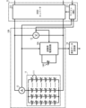
- FIG. 2 is a functional block diagram showing an example of a secondary battery charge/discharge system including the secondary battery evaluation system according to the first embodiment of the present invention.
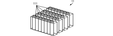
- FIG. 3 is a perspective view showing one embodiment of a battery pack.
- FIG. 4 is a functional block diagram showing an example of a secondary battery charge/discharge system including a secondary battery evaluation system according to the second embodiment of the present invention.
- FIG. 5 is a functional block diagram showing an example of a secondary battery evaluation system according to the third embodiment of the present invention.
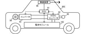
- FIG. 6 is a diagram showing an example of a schematic configuration of an EV to which the secondary battery evaluation system is applied.
- FIG. 7 is a functional block diagram showing an example of a battery module mounted on an EV.
- FIG. 8 is a functional block diagram showing an example of the configuration of a test system.
- Fig. 1 is a configuration diagram showing an example of a power system that uses a secondary battery to be evaluated in an embodiment of the present invention.
- the power system 90 includes a battery module 10, a solar panel 20, a storage battery PCS 31, a solar power PCS 32, a system control unit 40, a grid interconnection relay 50, a current sensor 60, and a business load.
- the power system 90 is not limited to systems in which the type of load is a business load, and the configuration of the present invention can be applied and will function effectively in any system in which the secondary battery (storage battery) of the battery module 10 is driven (charged and discharged) almost continuously.
- the power system 90 is equipped with a solar panel 20 and a solar PCS 32, but these can be omitted.
- the battery module 10 is connected to a storage battery PCS 31.
- the solar panel 20 is connected to a solar light PCS 32.
- the storage battery PCS 31 and the solar light PCS 32 are connected to a grid interconnection relay 50.
- the grid interconnection relay 50 is connected to a commercial power system.
- a current sensor 60 is disposed in the connection line between the grid interconnection relay 50 and the commercial power system.
- the battery module 10 is a so-called ESS (Energy Storage System) and includes multiple secondary battery cells 111.
- the multiple secondary battery cells 111 are charged or discharged by charge/discharge control from the storage battery PCS 31. A more specific configuration of the battery module 10 will be described later.
- the system control unit 40 controls the operation of the storage battery PCS 31 and the solar power PCS 32 so that the power of the business load is supplied by power from the solar power PCS 32 and power from the battery module 10. For example, the system control unit 40 predicts the power of the business load, and if the power of the business load can be supplied by the power generated by solar power and the power purchased up to the contract limit, it performs control to supply the power generated by solar power and the power purchased up to the contract limit to the business load. At this time, the system control unit 40 controls the operation of the solar power PCS 32 based on the current measured by the current sensor 60 so that power does not flow back into the commercial power grid.
- the system control unit 40 instructs the storage battery PCS 31 to control the discharge from the battery module 10.
- the system control unit 40 instructs the storage battery PCS 31 to control charging of the battery module 10.
- the storage battery PCS 31 controls the charging and discharging of the multiple secondary battery cells 111 of the battery module 10 based on instructions from the system control unit 40.
- (Secondary battery evaluation system) 2 is a functional block diagram showing an example of a charging/discharging system for a secondary battery including the evaluation system for a secondary battery according to the first embodiment of the present invention.
- the charging/discharging system for a secondary battery includes a battery module 10 and a PCS 31 for a storage battery.
- the storage battery PCS 31 includes a microcomputer 311 and a DCDC converter 312.
- the battery module 10 includes a battery pack 11, a current detection circuit 12, a voltage detection circuit 13, a test power supply circuit 19, and a test secondary battery 190.
- the battery pack 11 is formed by connecting multiple secondary battery cells 111 in series and in parallel.
- Figure 3 is a perspective view showing one embodiment of a battery pack.
- the multiple secondary battery cells 111 are grouped together in a two-dimensional arrangement, for example, as shown in Figure 3, to form the battery pack 11.
- the positive and negative terminals of the battery pack 11 are connected to the DCDC converter 312 of the storage battery PCS 31.
- the current detection circuit 12 is connected between the positive terminal of the battery pack 11 and the DCDC converter 312.
- the output terminal of the current detection circuit 12 is connected to the microcomputer 311. This allows the microcomputer 311 to obtain the current value of the battery pack 11.
- the voltage detection circuit 13 is connected between the positive and negative terminals of the battery pack 11.
- the output terminal of the voltage detection circuit 13 is connected to the microcomputer 311. This allows the microcomputer 311 to obtain the voltage value across the battery pack 11.
- the voltage detection circuit 13 may be configured to individually detect the cell voltage of each of the multiple secondary battery cells in the battery pack, and output the sum of these voltages as the voltage across the battery pack 11.
- the microcomputer 311 receives operational control from the system control unit 40 and controls the charging and discharging of the DCDC converter 312. At this time, the microcomputer 311 controls the charging and discharging based on the current value from the current detection circuit 12 and the voltage value from the voltage detection circuit 13.
- the test secondary battery 190 is manufactured from the same material as the multiple secondary battery cells 111. In other words, the test secondary battery 190 is the same as one of the secondary battery cells 111.
- the test secondary battery 190 may be composed of multiple secondary battery cells 111, provided that the number is less than the number of secondary battery cells 111 that make up the battery pack 11. However, it is preferable that the number is small. This simplifies the configuration of the test secondary battery 190, making it possible to reduce size and cost.
- test secondary battery 190 The positive and negative terminals of the test secondary battery 190 are connected to the test power supply circuit 19.
- the test power supply circuit 19 includes a charging circuit and an electronic load.
- the test power supply circuit 19 controls the charging of the test secondary battery 190 using the charging circuit.
- the test power supply circuit 19 controls the discharging of the test secondary battery 190 using the electronic load.
- the test power supply circuit 19 is connected to the microcomputer 311 of the storage battery PCS 31 and the measurement data transmission unit 18.
- the measurement data transmission unit 18 may be located inside or outside the battery module 10.
- the test power supply circuit 19 obtains the charging conditions (charging current value, charging voltage value) of the battery pack 11 from the microcomputer 311.
- the test power supply circuit 19 sets the charging voltage value and charging current value per unit cell of the multiple secondary battery cells 111 constituting the battery pack 11 to be the same as the test charging voltage value and test charging current value per unit cell of the test secondary battery 190.
- the test charging voltage value is set by dividing the voltage value across both ends of the battery pack 11 during charging by the number of secondary battery cells 111 connected in series in the battery pack 11.
- the test charging current value is set by dividing the current value of the battery pack 11 during charging by the number of secondary battery cells 111 connected in parallel in the battery pack 11.
- the test power supply circuit 19 controls the charging of the test secondary battery 190 using the test charging voltage value and the test charging current value.
- the test power supply circuit 19 obtains the discharge conditions (discharge current value, discharge voltage value) of the battery pack 11 from the microcomputer 311.
- the test power supply circuit 19 sets the discharge voltage value and discharge current value of the multiple secondary battery cells 111 that make up the battery pack 11 to be the same as the test discharge voltage value and test discharge current value of the test secondary battery 190.
- test discharge voltage value is set by dividing the voltage value across both ends of the battery pack 11 during discharge by the number of secondary battery cells 111 connected in series in the battery pack 11.
- test discharge current value is set by dividing the current value of the battery pack 11 during discharge by the number of secondary battery cells 111 connected in parallel in the battery pack 11.
- the test power supply circuit 19 controls the discharge of the test secondary battery 190 using the test discharge voltage value and the test discharge current value.
- the secondary battery evaluation system of this embodiment can make the degree of deterioration of the test secondary battery 190 the same as the degree of deterioration of the secondary battery cells 111 that make up the battery pack 11.
- test power supply circuit 19 When measuring SOC-OCV data, the test power supply circuit 19 temporarily stops simulating the charging and discharging of the battery pack 11 described above.
- the test power supply circuit 19 stores the SOC-OCV measurement conditions in advance.
- the test power supply circuit 19 outputs the measured SOC-OCV data to the measurement data transmission unit 18.
- the measurement data transmission unit 18 transmits the SOC-OCV data to an external device for analyzing the degree of deterioration, etc.
- the secondary battery evaluation system of this embodiment can obtain SOC-OCV data of the test secondary battery 190 without stopping the operation (charging and discharging) of the battery pack 11, and can perform OCV analysis of the test secondary battery 190.
- the deterioration level of the test secondary battery 190 accurately simulates the deterioration level of the secondary battery cells 111 of the battery pack 11. Therefore, by performing an OCV analysis of the test secondary battery 190, it is possible to perform an OCV analysis of the secondary battery cells 111 of the battery pack 11 with high accuracy. This allows the deterioration level of the secondary battery cells 111 of the battery pack 11 to be evaluated with high accuracy.
- the test power supply circuit 19 obtains the charging state of the battery pack 11 from the microcomputer 311, and resumes the simulation of the charging and discharging of the battery pack 11 described above. Then, when it is time to measure the next SOC-OCV data, the test power supply circuit 19 measures the SOC-OCV data described above. Thereafter, the simulation of the charging and discharging of the battery pack 11 and the measurement of the SOC-OCV data are repeated.
- the secondary battery evaluation system of this embodiment can continuously and accurately evaluate the degree of deterioration of the battery pack 11 (the secondary battery cells 111 of the battery pack 11).
- the test secondary battery 190 is disposed in the battery module 10, just like the battery pack 11. This makes the operating environment of the test secondary battery 190 similar to the operating environment (ambient temperature) of the battery pack 11. Therefore, the accuracy of simulating the deterioration level of the secondary battery cells 111 of the battery pack 11 using the test secondary battery 190 is improved. As a result, the secondary battery evaluation system of this embodiment can evaluate the deterioration level of the battery pack 11 (the secondary battery cells 111 of the battery pack 11) with even greater accuracy.
- Fig. 4 is a functional block diagram showing an example of a charging and discharging system for a secondary battery including the evaluation system for a secondary battery according to the second embodiment of the present invention.
- the secondary battery evaluation system according to the second embodiment differs from the secondary battery evaluation system according to the first embodiment in that it does not use a microcomputer 311, whereas the secondary battery evaluation system according to the first embodiment uses a microcomputer 311 in the storage battery PCS 31.
- the other configurations of the secondary battery evaluation system according to the second embodiment are similar to those of the secondary battery evaluation system according to the first embodiment, and a description of similar parts will be omitted.
- the secondary battery evaluation system includes a battery module 10A.
- the battery module 10A differs from the battery module 10 according to the first embodiment in the test power supply circuit 19A.
- the other configuration of the battery module 10A is the same as that of the battery module 10, and a description of the similar parts will be omitted.
- the secondary battery evaluation system of this embodiment does not include the microcomputer 311 of the storage battery PCS 31, and can accurately measure SOC-OCV data for evaluating the degree of deterioration of the battery pack 11 (secondary battery cells 111 of the battery pack 11) using only the battery module 10A.
- FIG. 5 is a functional block diagram showing an example of the secondary battery evaluation system according to the third embodiment of the present invention.
- the battery module 10B includes a battery pack 11, a current detection circuit 12, a voltage detection circuit 13, and a temperature sensor 16. That is, the battery module 10B does not include a test power supply circuit 19B or a test secondary battery 190.
- the temperature sensor 16 detects the ambient temperature of the battery pack 11 and outputs it to the transmitter 17.
- the current detection circuit 12 outputs the current value of the battery pack 11 to the transmitter 17.
- the voltage detection circuit 13 outputs the voltage value of the battery pack 11 to the transmitter 17.
- the transmitter 17 transmits the ambient temperature, current value, and voltage value to the receiver 194.
- the test power supply circuit 19B and the test secondary battery 190 are placed in the thermostatic chamber THCH.
- a temperature regulator 199 is installed in the thermostatic chamber THCH. The temperature regulator 199 adjusts the temperature of the thermostatic chamber THCH.
- the receiving unit 194 outputs the ambient temperature, the current value, and the voltage value to the condition setting unit 195.
- the condition setting unit 195 outputs the ambient temperature to the temperature regulator 199, and outputs the current value and the voltage value to the test power supply circuit 19B.
- the temperature regulator 199 adjusts the temperature of the thermostatic chamber THCH so that the temperature environment is the same as the received ambient temperature.
- the test power supply circuit 19B simulates charging and discharging the battery pack 11 for the test secondary battery 190 based on the received current and voltage values.
- the test power supply circuit 19B also measures the SOC-OCV data at a specified timing.
- OCV analysis and deterioration evaluation can be performed without placing the test secondary battery 190 near the battery pack 11 to be evaluated.
- the secondary battery evaluation system of the present application can also be applied to the evaluation of secondary batteries (EV batteries) for EVs (electric vehicles) and other vehicles that use electricity as a driving energy source.
- EV batteries secondary batteries
- EVs electric vehicles
- other vehicles that use electricity as a driving energy source.
- FIG. 6 is a diagram showing an example of the schematic configuration of an EV to which a secondary battery evaluation system is applied.
- FIG. 7 is a functional block diagram showing an example of a battery module mounted on an EV.
- FIG. 8 is a functional block diagram showing an example of a test system configuration. Note that the same reference numerals are used to designate functional units having the same configuration as in each of the above-mentioned embodiments, and in the following, descriptions of the parts with the same reference numerals will be omitted.
- the EV 90C includes an ECU 91, a DCDC converter 92, an inverter 93, a drive motor 94, a charging port 95, a wireless device 96, and a battery module 10C.
- the battery module 10C includes a battery pack 11, a current detection circuit 12, a voltage detection circuit 13, a temperature sensor 16, and a microcomputer 911.
- the ECU 91, the DCDC converter 92, the inverter 93, and the microcomputer 911 of the battery module 10C are connected to a CAN.
- the ECU 91 issues control commands to the DCDC converter 92, the inverter 93, and the battery module 10C via the CAN, and performs overall control of the EV 90C.
- the DCDC converter 92 is connected to the charging port 95 and to the inverter 93.
- the inverter 93 is connected to the drive motor 93.
- the DC-DC converter 92 converts the DC power supplied from the charging port 95 into a charging voltage and charging current for the battery pack 11 of the battery module 10C, and supplies charging power to the battery pack 11 of the battery module 10C.
- the DCDC converter 92 also converts the DC power charged in the battery pack 11 into a DC voltage for the inverter and supplies it to the inverter 93.
- the inverter 93 converts the DC current and DC voltage supplied through the DCDC converter 92 into a predetermined AC voltage and AC current, and supplies them to the drive motor 94.
- the wireless device 96 transmits the ambient temperature, current value, and voltage value obtained through the microcomputer 911 and ECU 91 to a wireless communication unit 194C that is located in a thermostatic chamber THCH in a separate location from the EV 90C.
- a battery pack including a plurality of secondary battery cells; a voltage detection circuit for detecting a voltage value between both ends of the battery pack; a current detection circuit for detecting a current value of the battery pack;
- a test secondary battery including at least one battery cell made of the same material as the secondary battery cell; a power supply circuit for controlling charging and discharging of the test secondary battery; Equipped with The power supply circuit includes: setting a test charging voltage value and a test charging current value for the test secondary battery based on the both-end voltage value and the current value during charging of the battery pack, and charging the test secondary battery at the test charging voltage value and the test charging current value; setting a test discharge voltage value and a test discharge current value for the test secondary battery based on the end-to-end voltage value and the current value during discharging of the battery pack, and discharging the test secondary battery at the test discharge voltage value and the test discharge current value, thereby simulating charging and discharging of the battery pack;
- ⁇ 2> The secondary battery evaluation system described in ⁇ 1>, in which the test secondary battery is disposed within a battery module that incorporates the battery pack.
- a temperature sensor for detecting an ambient temperature of the battery pack; a transmitter that transmits the voltage value, the current value, and the ambient temperature; a receiving unit that receives the voltage value between both ends, the current value, and the ambient temperature of the battery pack from the transmitting unit;
- a thermostatic chamber Equipped with the battery pack, the voltage detection circuit, the current detection circuit, the temperature sensor, and the transmitter are disposed at a first location; the test secondary battery, the power supply circuit, the receiving unit, and the thermostatic chamber are disposed at a second location different from the first location;
- the test secondary battery is placed in the thermostatic chamber,
- the secondary battery evaluation system according to ⁇ 1> or ⁇ 2>, wherein the thermostatic chamber is controlled to reproduce an ambient temperature of the battery pack.
- ⁇ 4> The secondary battery evaluation system described in ⁇ 3>, wherein the battery pack is a driving battery for an electric vehicle.
Landscapes
- Chemical & Material Sciences (AREA)
- Chemical Kinetics & Catalysis (AREA)
- Electrochemistry (AREA)
- General Chemical & Material Sciences (AREA)
- Engineering & Computer Science (AREA)
- Manufacturing & Machinery (AREA)
- Physics & Mathematics (AREA)
- General Physics & Mathematics (AREA)
- Secondary Cells (AREA)
- Charge And Discharge Circuits For Batteries Or The Like (AREA)
Abstract
二次電池の評価システムは、複数の二次電池セル(111)から構成される電池パック(11)と、電池パック(11)の両端電圧値を検出する電圧検出回路(13)と、電池パック(11)の電流値を検出する電流検出回路(12)と、二次電池セル(111)と同一材料で製造された少なくとも1つの電池セルから構成される試験用二次電池(190)と、試験用二次電池(190)の充放電を制御する試験用電源回路(19)と、を備える。試験用電源回路(19)は、電池パック(11)の充電時における両端電圧値と電流値とに基づいて、試験用二次電池(190)に対する試験用充電電圧値および試験用充電電流値とを設定し、試験用充電電圧値と試験用充電電流値とで試験用二次電池(190)を充電し、電池パック(11)の放電時における両端電圧値と電流値とに基づいて、試験用二次電池(190)に対する試験用放電電圧値および試験用放電電流値とを設定し、試験用放電電圧値と試験用放電電流値とで試験用二次電池(190)を放電することで、電池パック(11)の充放電の模擬を行う。試験用電源回路(19)は、SOC-OCVデータの測定時には、試験用二次電池(190)の充放電を電池パック(11)の駆動と独立して行い、試験用二次電池(190)のSOC-OCVデータを取得する。
Description
本発明は、二次電池の劣化度を評価するシステムに関する。
特許文献1には、電池状態検出装置が記載されている。特許文献1に記載の電池状態検出装置は、車両のモータ等に電力を供給する電池(二次電池)を劣化度の評価対象の電池としており、劣化度の評価対象の電池に対して、劣化度の監視用電池が並列に接続されている。
特許文献1に記載の電池状態検出装置は、監視用電池を用いて、評価対象の電池の状態を検出する。
しかしながら、特許文献1の装置では、評価対象の電池の動作中に、監視用電池も動作中となる。このため、評価対象の電池が動作中には、評価対象の電池のOCV劣化解析のような静的な評価ができず、劣化度の評価を精度よく行うことができない。
また、評価対象の電池に対してOCV劣化解析のような静的な評価を行う場合、長時間が必要になる。このため、例えば、UPSのバッテリのように稼働を停止できないシステムには適用できない。
したがって、本発明の目的は、評価対象の電池(二次電池)の動作を停止させることなく、評価対象の電池の劣化度の評価を精度よく行う二次電池の評価システムを提供することにある。
この発明の二次電池の評価システムは、複数の二次電池セルから構成される電池パックと、電池パックの両端電圧値を検出する電圧検出回路と、電池パックの電流値を検出する電流検出回路と、二次電池セルと同一材料で製造された少なくとも1つの電池セルから構成される試験用二次電池と、試験用二次電池の充放電を制御する電源回路と、を備える。
電源回路は、電池パックの充電時における両端電圧値と電流値とに基づいて、試験用二次電池に対する試験用充電電圧値および試験用充電電流値とを設定し、試験用充電電圧値と試験用充電電流値とで試験用二次電池を充電し、電池パックの放電時における両端電圧値と電流値とに基づいて、試験用二次電池に対する試験用放電電圧値および試験用放電電流値とを設定し、試験用放電電圧値と試験用放電電流値とで試験用二次電池を放電することで、電池パックの充放電の模擬を行う。電源回路は、SOC-OCVデータの測定時には、試験用二次電池の充放電を電池パックの駆動と独立して行い、試験用二次電池のSOC-OCVデータを取得する。
この構成では、試験用二次電池の充電および放電を、電池パックの駆動に対して分離して行うことができる。これにより、電池パックが駆動中であっても、試験用二次電池の静的な評価を実現できる。また、試験用二次電池が電池パックの二次電池セルと同一材料で製造されていることで、試験用二次電池の劣化度に関する特性を測定できれば、電池パックの劣化度に関する特性を、間接的かつ高精度に実現できる。
この発明よれば、評価対象の二次電池の動作を停止させることなく、評価対象の二次電池の劣化度の評価を精度よく行うことができる。
[第1の実施形態]
本発明の第1の実施形態に係る二次電池の評価システムについて、図を参照して説明する。
本発明の第1の実施形態に係る二次電池の評価システムについて、図を参照して説明する。
(二次電池が利用される電力システム)
図1は、本発明の実施形態において評価対象となる二次電池が利用される電力システムの一例を示す構成図である。図1に示すように、電力システム90は、電池モジュール10、太陽光パネル20、蓄電池用PCS31、太陽光用PCS32、システム制御部40、系統連系リレー50、電流センサ60、および、事業者負荷を備える。
図1は、本発明の実施形態において評価対象となる二次電池が利用される電力システムの一例を示す構成図である。図1に示すように、電力システム90は、電池モジュール10、太陽光パネル20、蓄電池用PCS31、太陽光用PCS32、システム制御部40、系統連系リレー50、電流センサ60、および、事業者負荷を備える。
なお、電力システム90は、負荷の種類が事業者負荷のシステムに限るものではなく、電池モジュール10の二次電池(蓄電池)がほぼ継続的に駆動(充放電)されるシステムであれば、本願発明の構成は適用でき、有効に作用する。また、電力システム90は、太陽光パネル20と太陽光用PCS32を備えているが、これらは省略することも可能である。
電池モジュール10は、蓄電池用PCS31に接続される。太陽光パネル20は、太陽光用PCS32に接続される。蓄電池用PCS31と太陽光用PCS32とは、系統連系リレー50に接続される。系統連系リレー50は、商用電力系統に接続される。系統連系リレー50と商用電力系統との接続ラインには、電流センサ60が配置される。
電池モジュール10は、いわゆる、ESS(Energy Storage System)であり、複数の二次電池セル111を備えている。複数の二次電池セル111は、蓄電池用PCS31からの充放電制御によって、充電または放電される。なお、電池モジュール10のより具体的な構成は、後述する。
システム制御部40は、太陽光用PCS32から電力と電池モジュール10からの電力で事業所負荷の電力を賄うように、蓄電池用PCS31および太陽光用PCS32の動作を制御する。例えば、システム制御部40は、事業者負荷の電力を予測し、太陽光発電の電力と契約上限までの買電電力とで事業者負荷の電力を賄えれば、太陽光発電の電力と契約上限までの買電電力とを事業者負荷に供給する制御を行う。この際、システム制御部40は、電流センサ60で計測した電流に基づいて、商用電力系統に電力が逆潮流しないように、太陽光用PCS32の動作を制御する。
また、システム制御部40は、太陽光発電の電力と契約上限までの買電電力とで事業者負荷の電力を賄えず、電池モジュール10が十分に充電されていれば、電池モジュール10からの放電制御を蓄電池用PCS31に指示する。
また、システム制御部40は、太陽光発電の電力と契約上限までの買電電力とで事業者負荷の電力を賄え、さらに、太陽光発電電力に余力があり、電池モジュール10に充電可能な容量が存在すれば、電池モジュール10への充電制御を蓄電池用PCS31に指示する。
蓄電池用PCS31は、システム制御部40からの指示に基づいて、電池モジュール10の複数の二次電池セル111の充放電制御を行う。
(二次電池の評価システム)
図2は、本発明の第1の実施形態に係る二次電池の評価システムを含む二次電池の充放電システムの一例を示す機能ブロック図である。図2に示すように、二次電池の充放電システムは、電池モジュール10、および、蓄電池用PCS31を備える。
図2は、本発明の第1の実施形態に係る二次電池の評価システムを含む二次電池の充放電システムの一例を示す機能ブロック図である。図2に示すように、二次電池の充放電システムは、電池モジュール10、および、蓄電池用PCS31を備える。
蓄電池用PCS31は、マイコン311、および、DCDCコンバータ312を備える。電池モジュール10は、電池パック11、電流検出回路12、電圧検出回路13、試験用電源回路19、試験用二次電池190を備える。
電池パック11は、複数の二次電池セル111を直列接続、および、並列接続することで構成される。図3は、電池パックの一態様を示す斜視図である。複数の二次電池セル111は、例えば図3に示すように二次元配置された状態でまとめられることで、電池パック11を構成する。
電池パック11の正極端子と負極端子は、蓄電池用PCS31のDCDCコンバータ312に接続される。
電流検出回路12は、電池パック11の正極端子とDCDCコンバータ312との間に接続される。電流検出回路12の出力端子は、マイコン311に接続される。これにより、マイコン311は、電池パック11の電流値を取得できる。
電圧検出回路13は、電池パック11の正極端子と負極端子との間に接続される。電圧検出回路13の出力端子は、マイコン311に接続される。これにより、マイコン311は、電池パック11の両端電圧値を取得できる。電圧検出回路13は、電池パック内の複数の二次電池セルの各々のセル電圧を個別に検出するように構成し、その合計値を電池パック11の両端電圧として出力するようにしてもよい。
マイコン311は、システム制御部40からの動作制御を受けて、DCDCコンバータ312の充放電制御を行う。この際、マイコン311は、電流検出回路12からの電流値および電圧検出回路13からの電圧値に基づいて充放電制御を行う。
試験用二次電池190は、複数の二次電池セル111と同一材料で製造されている。すなわち、試験用二次電池190は、二次電池セル111の1個と同じものである。なお、試験用二次電池190は、電池パック11を構成する二次電池セル111の個数よりも少なければ、複数個の二次電池セル111から構成してもよい。しかしながら、その個数は、少ない方が好ましい。これにより、試験用二次電池190の構成を簡素化でき、小型化、低コスト化を実現できる。
試験用二次電池190の正極端子と負極端子は、試験用電源回路19に接続される。
試験用電源回路19は、充電回路と電子負荷とを備える。試験用電源回路19は、充電回路によって試験用二次電池190の充電制御を行う。試験用電源回路19は、電子負荷によって試験用二次電池190の放電制御を行う。
試験用電源回路19は、蓄電池用PCS31のマイコン311、および、測定データ送信部18に接続する。測定データ送信部18は、電池モジュール10の内部に配置されていても、外部に配置されていてもよい。
(電池パック11の充放電の模擬)
試験用電源回路19は、マイコン311から電池パック11の充電条件(充電電流値、充電電圧値)を取得する。試験用電源回路19は、電池パック11を構成する複数の二次電池セル111の単セル当たりの充電電圧値および充電電流値と試験用二次電池190の単セル当たりの試験用充電電圧値および試験用充電電流値とが同じになるように設定する。
試験用電源回路19は、マイコン311から電池パック11の充電条件(充電電流値、充電電圧値)を取得する。試験用電源回路19は、電池パック11を構成する複数の二次電池セル111の単セル当たりの充電電圧値および充電電流値と試験用二次電池190の単セル当たりの試験用充電電圧値および試験用充電電流値とが同じになるように設定する。
例えば、試験用充電電圧値は、電池パック11における直列接続された二次電池セル111の個数によって充電時の電池パック11の両端電圧値を除算することで設定される。
例えば、試験用充電電流値は、電池パック11における並列接続された二次電池セル111の個数によって充電時の電池パック11の電流値を除算することで設定される。
試験用電源回路19は、試験用充電電圧値および試験用充電電流値によって、試験用二次電池190の充電制御を行う。
試験用電源回路19は、マイコン311から電池パック11の放電条件(放電電流値、放電電圧値)を取得する。試験用電源回路19は、電池パック11を構成する複数の二次電池セル111の放電電圧値および放電電流値と、試験用二次電池190の試験用放電電圧値および試験用放電電流値とが同じになるように設定する。
例えば、試験用放電電圧値は、電池パック11における直列接続された二次電池セル111の個数によって放電時の電池パック11の両端電圧値を除算することで設定される。
例えば、試験用放電電流値は、電池パック11における並列接続された二次電池セル111の個数によって放電時の電池パック11の電流値を除算することで設定される。
試験用電源回路19は、試験用放電電圧値および試験用放電電流値によって、試験用二次電池190の放電制御を行う。
このような模擬の充放電を行うことで、本実施形態の二次電池の評価システムは、試験用二次電池190の劣化度を、電池パック11を構成する二次電池セル111の劣化度と同じにできる。
(SOC-OCVデータの測定時)
SOC-OCVデータの測定を行うとき、試験用電源回路19は、上述の電池パック11の充放電の模擬を一時的に停止する。
SOC-OCVデータの測定を行うとき、試験用電源回路19は、上述の電池パック11の充放電の模擬を一時的に停止する。
試験用電源回路19は、SOC-OCV測定条件を予め記憶している。
試験用電源回路19は、SOC-OCV測定に先立ち、試験用二次電池190を完全放電状態(SOC0%)まで放電する。その後、SOC-OCV測定用の間欠充電を行い、満充電状態(SOC100%)までのSOC-OCVデータ(充電容量と開回路電圧)を測定する。具体的には、試験用二次電池190が完全放電状態(SOC0%)から、所定電流で所定時間充電(例えば1Cで1分間)した後、上昇した端子電圧を落ち着かせるための緩和時間(例えば10分間)を挟み、平衡状態になった後の端子電圧をOCVデータとして測定する、という手順を満充電になるまで繰り返す。こうすることでSOCの変位と共にOCV値がどう変化しているかを示すSOC-OCVデータを取得することができる。
試験用電源回路19は、測定したSOC-OCVデータを測定データ送信部18に出力する。測定データ送信部18は、外部の劣化度解析用の装置等にSOC-OCVデータを送信する。
これにより、本実施形態の二次電池の評価システムは、電池パック11の駆動(充放電)を停止することなく、試験用二次電池190のSOC-OCVデータを取得でき、試験用二次電池190のOCV解析を実現できる。
この際、上述のように、試験用二次電池190の劣化度は、電池パック11の二次電池セル111の劣化度を精度よく模擬している。したがって、試験用二次電池190のOCV解析を行うことで、電池パック11の二次電池セル111のOCV解析を精度よく行うことができる。これにより、電池パック11の二次電池セル111の劣化度を精度よく評価できる。
なお、このSOC-OCVデータの測定が終了すると、試験用電源回路19は、マイコン311から電池パック11の充電状態を取得し、上述の電池パック11の充放電の模擬を再開する。そして、また次のSOC-OCVデータの測定タイミングになると、試験用電源回路19は、上述のSOC-OCVデータの測定を行う。以下、電池パック11の充放電の模擬とSOC-OCVデータの測定を繰り返す。
これにより、本実施形態の二次電池の評価システムは、電池パック11(電池パック11の二次電池セル111)の劣化度を継続的に精度よく評価できる。
また、上述の構成では、試験用二次電池190は、電池パック11と同じく、電池モジュール10内に配置されている。これにより、試験用二次電池190の動作環境は、電池パック11の動作環境(環境温度)と同様になる。したがって、試験用二次電池190を用いた電池パック11の二次電池セル111の劣化度の模擬精度は向上する。この結果、本実施形態の二次電池の評価システムは、電池パック11(電池パック11の二次電池セル111)の劣化度を、さらに精度よく評価できる。
[第2の実施形態]
本発明の第2の実施形態に係る二次電池の評価システムについて、図を参照して説明する。図4は、本発明の第2の実施形態に係る二次電池の評価システムを含む二次電池の充放電システムの一例を示す機能ブロック図である。
本発明の第2の実施形態に係る二次電池の評価システムについて、図を参照して説明する。図4は、本発明の第2の実施形態に係る二次電池の評価システムを含む二次電池の充放電システムの一例を示す機能ブロック図である。
第2の実施形態に係る二次電池の評価システムは、第1の実施形態に係る二次電池の評価システムが蓄電池用PCS31のマイコン311を利用するのに対して、マイコン311を利用しない点で異なる。第2の実施形態に係る二次電池の評価システムの他の構成は、第1の実施形態に係る二次電池の評価システムと同様であり、同様の箇所の説明は省略する。
二次電池の評価システムは、電池モジュール10Aを備える。電池モジュール10Aは、第1の実施形態に係る電池モジュール10に対して、試験用電源回路19Aにおいて異なる。電池モジュール10Aの他の構成は、電池モジュール10と同様であり、同様の箇所の説明は省略する。
試験用電源回路19Aは、電流検出回路12の出力端子および電圧検出回路13の出力端子に接続する。試験用電源回路19Aは、電池パック11の電流値を電流検出回路12から直接取得する。試験用電源回路19Aは、電池パック11の両端電圧値を電圧検出回路13から直接取得する。
これにより、本実施形態の二次電池の評価システムは、蓄電池用PCS31のマイコン311を含むことなく、電池モジュール10Aのみで、電池パック11(電池パック11の二次電池セル111)の劣化度を評価するためのSOC-OCVデータを精度よく測定できる。
[第3の実施形態]
本発明の第3の実施形態に係る二次電池の評価システムについて、図を参照して説明する。図5は、本発明の第3の実施形態に係る二次電池の評価システムの一例を示す機能ブロック図である。
本発明の第3の実施形態に係る二次電池の評価システムについて、図を参照して説明する。図5は、本発明の第3の実施形態に係る二次電池の評価システムの一例を示す機能ブロック図である。
第3の実施形態に係る二次電池の評価システムは、第2の実施形態に係る二次電池の評価システムに対して、試験用電源回路19B、試験用二次電池190等が、電池モジュール10Bと別の場所に配置される点で異なる。以下では、第3の実施形態に係る二次電池の評価システムが第2の実施形態に係る二次電池の評価システムに対して異なる箇所のみを説明し、同様の箇所の説明は省略する。
(電池モジュール10Bが配置される第1の場所)
電池モジュール10Bは、電池パック11、電流検出回路12、電圧検出回路13、および、温度センサ16を備える。すなわち、電池モジュール10Bは、試験用電源回路19B、試験用二次電池190を備えていない。
電池モジュール10Bは、電池パック11、電流検出回路12、電圧検出回路13、および、温度センサ16を備える。すなわち、電池モジュール10Bは、試験用電源回路19B、試験用二次電池190を備えていない。
温度センサ16は、電池パック11の周辺温度を検出し、送信部17に出力する。電流検出回路12は、電池パック11の電流値を送信部17に出力する。電圧検出回路13、電池パック11の電圧値を送信部17に出力する。
送信部17は、周辺温度、電流値、および、電圧値を、受信部194に送信する。
(試験用二次電池および試験用電源回路が配置される第2の場所)
受信部194、条件設定部195、試験用電源回路19B、試験用二次電池190、測定データ送信部18は、電池モジュール10Bと異なる場所に配置される。例えば、これらは、OCV解析を行うユーザ等がいる試験場等に配置される。
受信部194、条件設定部195、試験用電源回路19B、試験用二次電池190、測定データ送信部18は、電池モジュール10Bと異なる場所に配置される。例えば、これらは、OCV解析を行うユーザ等がいる試験場等に配置される。
試験用電源回路19B、試験用二次電池190は、恒温槽THCH内に配置される。恒温槽THCHには、温調器199が設置されている。温調器199は、恒温槽THCHの温度を調整する。
受信部194は、周辺温度、電流値、および、電圧値を条件設定部195に出力する。条件設定部195は、周辺温度を温調器199に出力し、電流値、および、電圧値を試験用電源回路19Bに出力する。
温調器199は、受信した周辺温度と同じ温度環境となるように、恒温槽THCHの温度調整を行う。
試験用電源回路19Bは、受信した電流値、および、電圧値に基づいて、試験用二次電池190に対して、電池パック11の充放電の模擬を行う。また、試験用電源回路19Bは、所定のタイミングで、SOC-OCVデータの測定を行う。
このように、本実施形態の構成とすることで、評価対象の電池パック11の近傍に試験用二次電池190を配置せずに、OCV解析、劣化度の評価を行うことができる。これにより、遠隔地においてOCV解析の専門家に評価を容易にゆだねる事ができる。例えば、電池メーカがESSを運用している顧客先に行かずとも、自社内に試験用二次電池190を置いたシステムによって顧客先で運用されているESS用電池(電池パック11)の劣化度を高精度に評価できる。
なお、上述の説明では、工場等を想定して記載しているが、本願の二次電池の評価システムは、電気を駆動用のエネルギーとして利用するEV(電気自動車)等の二次電池(EVバッテリ)の評価にも適用できる。
図6は、二次電池の評価システムを適用したEVの概略構成の一例を示す図である。図7は、EVに搭載される電池モジュールの一例を示す機能ブロック図である。図8は、試験系の構成の一例を示す機能ブロック図である。なお、上述の各実施形態と同様の構成からなる機能部は、同じ符号を付記しており、以下では、同じ符号の箇所は説明を省略する。
図6に示すように、EV90Cは、ECU91、DCDCコンバータ92、インバータ93、駆動モータ94、充電口95、無線装置96、および、電池モジュール10Cを備える。
図7に示すように、電池モジュール10Cは、電池パック11、電流検出回路12、電圧検出回路13、温度センサ16、および、マイコン911を備える。
ECU91、DCDCコンバータ92、インバータ93、および、電池モジュール10Cのマイコン911は、CANに接続される。ECU91は、CANを通じてDCDCコンバータ92、インバータ93、および、電池モジュール10Cに制御指令を行い、EV90Cの全体制御を行う。
DCDCコンバータ92は、充電口95に接続し、インバータ93に接続する。インバータ93は、駆動モータ93に接続する。
DCDCコンバータ92は、充電口95から供給される直流電力を、電池モジュール10Cの電池パック11の充電電圧、充電電流に変換して、電池モジュール10Cの電池パック11の充電電力を供給する。
また、DCDCコンバータ92は、電池パック11に充電された直流電力を、インバータ用の直流電圧、直流電圧に変換して、インバータ93に供給する。
インバータ93は、DCDCコンバータ92を通じて供給された直流電流、直流電圧を、所定の交流電圧、交流電流に変換して、駆動モータ94に供給する。
無線装置96は、マイコン911、ECU91を通じて取得した周辺温度、電流値、および、電圧値を、EV90Cと別位置の恒温槽THCHに配置された無線通信部194Cに送信する。
これにより、上述の第3の実施形態に示したような恒温槽THCHを用いたSOC-OCVデータの測定を行うことができる。
<1> 複数の二次電池セルから構成される電池パックと、
前記電池パックの両端電圧値を検出する電圧検出回路と、
前記電池パックの電流値を検出する電流検出回路と、
前記二次電池セルと同一材料で製造された少なくとも1つの電池セルから構成される試験用二次電池と、
前記試験用二次電池の充放電を制御する電源回路と、
を備え、
前記電源回路は、
前記電池パックの充電時における前記両端電圧値と前記電流値とに基づいて、前記試験用二次電池に対する試験用充電電圧値および試験用充電電流値とを設定し、前記試験用充電電圧値と前記試験用充電電流値とで前記試験用二次電池を充電し、
前記電池パックの放電時における前記両端電圧値と前記電流値とに基づいて、前記試験用二次電池に対する試験用放電電圧値および試験用放電電流値とを設定し、前記試験用放電電圧値と前記試験用放電電流値とで前記試験用二次電池を放電することで、前記電池パックの充放電の模擬を行い、
SOC-OCVデータの測定時には、前記試験用二次電池の充放電を前記電池パックの駆動と独立して行い、前記試験用二次電池のSOC-OCVデータを取得する、
二次電池の評価システム。
前記電池パックの両端電圧値を検出する電圧検出回路と、
前記電池パックの電流値を検出する電流検出回路と、
前記二次電池セルと同一材料で製造された少なくとも1つの電池セルから構成される試験用二次電池と、
前記試験用二次電池の充放電を制御する電源回路と、
を備え、
前記電源回路は、
前記電池パックの充電時における前記両端電圧値と前記電流値とに基づいて、前記試験用二次電池に対する試験用充電電圧値および試験用充電電流値とを設定し、前記試験用充電電圧値と前記試験用充電電流値とで前記試験用二次電池を充電し、
前記電池パックの放電時における前記両端電圧値と前記電流値とに基づいて、前記試験用二次電池に対する試験用放電電圧値および試験用放電電流値とを設定し、前記試験用放電電圧値と前記試験用放電電流値とで前記試験用二次電池を放電することで、前記電池パックの充放電の模擬を行い、
SOC-OCVデータの測定時には、前記試験用二次電池の充放電を前記電池パックの駆動と独立して行い、前記試験用二次電池のSOC-OCVデータを取得する、
二次電池の評価システム。
<2> 前記試験用二次電池は、前記電池パックを内蔵する電池モジュール内に配置されている、<1>に記載の二次電池の評価システム。
<3> 前記電池パックの周辺温度を検出する温度センサと、
前記両端電圧値、前記電流値、および、前記周辺温度を送信する送信部と、
前記送信部からの前記両端電圧値、前記電流値、および、前記電池パックの周辺温度を受信する受信部と、
恒温槽と、
を備え、
前記電池パック、前記電圧検出回路、前記電流検出回路、前記温度センサ、および、送信部は、第1の場所に配置され、
前記試験用二次電池、前記電源回路、前記受信部、および、前記恒温槽は、前記第1の場所と異なる第2の場所に配置され、
前記試験用二次電池は、前記恒温槽内に配置され、
前記恒温槽は、前記電池パックの周辺温度を再現するように制御されている、<1>または<2>に記載の二次電池の評価システム。
前記両端電圧値、前記電流値、および、前記周辺温度を送信する送信部と、
前記送信部からの前記両端電圧値、前記電流値、および、前記電池パックの周辺温度を受信する受信部と、
恒温槽と、
を備え、
前記電池パック、前記電圧検出回路、前記電流検出回路、前記温度センサ、および、送信部は、第1の場所に配置され、
前記試験用二次電池、前記電源回路、前記受信部、および、前記恒温槽は、前記第1の場所と異なる第2の場所に配置され、
前記試験用二次電池は、前記恒温槽内に配置され、
前記恒温槽は、前記電池パックの周辺温度を再現するように制御されている、<1>または<2>に記載の二次電池の評価システム。
<4> 前記電池パックは、電動車両の駆動用電池である、<3>に記載の二次電池の評価システム。
10、10A、10B、10C:電池モジュール
11:電池パック
12:電流検出回路
13:電圧検出回路
16:温度センサ
17:送信部
18:測定データ送信部
19、19A、19B:試験用電源回路
20:太陽光パネル
31:蓄電池用PCS
32:太陽光用PCS
40:システム制御部
50:系統連系リレー
60:電流センサ
90:電力システム
90C:EV
91:ECU
92:DCDCコンバータ
93:インバータ
94:駆動モータ
95:充電口
96:無線装置
111:二次電池セル
190:試験用二次電池
194:受信部
194C:無線通信部
195:条件設定部
199:温調器
311:マイコン
312:DCDCコンバータ
911:マイコン
THCH:恒温槽
11:電池パック
12:電流検出回路
13:電圧検出回路
16:温度センサ
17:送信部
18:測定データ送信部
19、19A、19B:試験用電源回路
20:太陽光パネル
31:蓄電池用PCS
32:太陽光用PCS
40:システム制御部
50:系統連系リレー
60:電流センサ
90:電力システム
90C:EV
91:ECU
92:DCDCコンバータ
93:インバータ
94:駆動モータ
95:充電口
96:無線装置
111:二次電池セル
190:試験用二次電池
194:受信部
194C:無線通信部
195:条件設定部
199:温調器
311:マイコン
312:DCDCコンバータ
911:マイコン
THCH:恒温槽
Claims (4)
- 複数の二次電池セルから構成される電池パックと、
前記電池パックの両端電圧値を検出する電圧検出回路と、
前記電池パックの電流値を検出する電流検出回路と、
前記二次電池セルと同一材料で製造された少なくとも1つの電池セルから構成される試験用二次電池と、
前記試験用二次電池の充放電を制御する電源回路と、
を備え、
前記電源回路は、
前記電池パックの充電時における前記両端電圧値と前記電流値とに基づいて、前記試験用二次電池に対する試験用充電電圧値および試験用充電電流値とを設定し、前記試験用充電電圧値と前記試験用充電電流値とで前記試験用二次電池を充電し、
前記電池パックの放電時における前記両端電圧値と前記電流値とに基づいて、前記試験用二次電池に対する試験用放電電圧値および試験用放電電流値とを設定し、前記試験用放電電圧値と前記試験用放電電流値とで前記試験用二次電池を放電することで、前記電池パックの充放電の模擬を行い、
SOC-OCVデータの測定時には、前記試験用二次電池の充放電を前記電池パックの駆動と独立して行い、前記試験用二次電池のSOC-OCVデータを取得する、
二次電池の評価システム。 - 前記試験用二次電池は、前記電池パックを内蔵する電池モジュール内に配置されている、
請求項1に記載の二次電池の評価システム。 - 前記電池パックの周辺温度を検出する温度センサと、
前記両端電圧値、前記電流値、および、前記周辺温度を送信する送信部と、
前記送信部からの前記両端電圧値、前記電流値、および、前記電池パックの周辺温度を受信する受信部と、
恒温槽と、
を備え、
前記電池パック、前記電圧検出回路、前記電流検出回路、前記温度センサ、および、送信部は、第1の場所に配置され、
前記試験用二次電池、前記電源回路、前記受信部、および、前記恒温槽は、前記第1の場所と異なる第2の場所に配置され、
前記試験用二次電池は、前記恒温槽内に配置され、
前記恒温槽は、前記電池パックの周辺温度を再現するように制御されている、
請求項1に記載の二次電池の評価システム。 - 前記電池パックは、電動車両の駆動用電池である、請求項3に記載の二次電池の評価システム。
Priority Applications (2)
| Application Number | Priority Date | Filing Date | Title |
|---|---|---|---|
| JP2025531527A JPWO2025009474A1 (ja) | 2023-07-04 | 2024-06-28 | |
| US19/419,450 US20260104467A1 (en) | 2023-07-04 | 2025-12-15 | Secondary battery evaluation system |
Applications Claiming Priority (2)
| Application Number | Priority Date | Filing Date | Title |
|---|---|---|---|
| JP2023-109914 | 2023-07-04 | ||
| JP2023109914 | 2023-07-04 |
Related Child Applications (1)
| Application Number | Title | Priority Date | Filing Date |
|---|---|---|---|
| US19/419,450 Continuation US20260104467A1 (en) | 2023-07-04 | 2025-12-15 | Secondary battery evaluation system |
Publications (1)
| Publication Number | Publication Date |
|---|---|
| WO2025009474A1 true WO2025009474A1 (ja) | 2025-01-09 |
Family
ID=94172140
Family Applications (1)
| Application Number | Title | Priority Date | Filing Date |
|---|---|---|---|
| PCT/JP2024/023445 Ceased WO2025009474A1 (ja) | 2023-07-04 | 2024-06-28 | 二次電池の評価システム |
Country Status (3)
| Country | Link |
|---|---|
| US (1) | US20260104467A1 (ja) |
| JP (1) | JPWO2025009474A1 (ja) |
| WO (1) | WO2025009474A1 (ja) |
Citations (5)
| Publication number | Priority date | Publication date | Assignee | Title |
|---|---|---|---|---|
| JPH11289676A (ja) * | 1998-04-01 | 1999-10-19 | Toyo System Kk | 二次電池充放電装置用の電源装置 |
| JP2009025032A (ja) * | 2007-07-17 | 2009-02-05 | Toyota Motor Corp | 電池状態検出装置及び方法、並びに出力制御装置及び方法 |
| JP2014154437A (ja) * | 2013-02-12 | 2014-08-25 | Toshiba Corp | 試験システムおよび試験方法 |
| JP2014220896A (ja) * | 2013-05-07 | 2014-11-20 | 東芝Itコントロールシステム株式会社 | 充放電制御装置 |
| JP2023010581A (ja) * | 2021-07-07 | 2023-01-20 | 株式会社東京精密 | 充放電試験システム及び充放電試験システムの制御方法 |
-
2024
- 2024-06-28 WO PCT/JP2024/023445 patent/WO2025009474A1/ja not_active Ceased
- 2024-06-28 JP JP2025531527A patent/JPWO2025009474A1/ja active Pending
-
2025
- 2025-12-15 US US19/419,450 patent/US20260104467A1/en active Pending
Patent Citations (5)
| Publication number | Priority date | Publication date | Assignee | Title |
|---|---|---|---|---|
| JPH11289676A (ja) * | 1998-04-01 | 1999-10-19 | Toyo System Kk | 二次電池充放電装置用の電源装置 |
| JP2009025032A (ja) * | 2007-07-17 | 2009-02-05 | Toyota Motor Corp | 電池状態検出装置及び方法、並びに出力制御装置及び方法 |
| JP2014154437A (ja) * | 2013-02-12 | 2014-08-25 | Toshiba Corp | 試験システムおよび試験方法 |
| JP2014220896A (ja) * | 2013-05-07 | 2014-11-20 | 東芝Itコントロールシステム株式会社 | 充放電制御装置 |
| JP2023010581A (ja) * | 2021-07-07 | 2023-01-20 | 株式会社東京精密 | 充放電試験システム及び充放電試験システムの制御方法 |
Also Published As
| Publication number | Publication date |
|---|---|
| US20260104467A1 (en) | 2026-04-16 |
| JPWO2025009474A1 (ja) | 2025-01-09 |
Similar Documents
| Publication | Publication Date | Title |
|---|---|---|
| JP7040601B2 (ja) | 電池制御装置、電池制御方法、無停電電源装置、電力システム及び電動車両 | |
| US10992144B2 (en) | Battery balancing and current control with bypass circuit for load switch | |
| JP5715694B2 (ja) | 電池制御装置、電池システム | |
| KR101015185B1 (ko) | 상태검지장치 및 이것을 이용하는 장치 | |
| US4390841A (en) | Monitoring apparatus and method for battery power supply | |
| CN113811781A (zh) | 电池诊断装置和方法 | |
| US20140184236A1 (en) | Battery control apparatus and battery system | |
| Manas et al. | Designing a battery Management system for electric vehicles: A congregated approach | |
| US20140239914A1 (en) | Battery controller | |
| TW200410433A (en) | Detecting method and detecting apparatus for detecting internal of rechargeable battery, rechargeable battery pack having said detecting apparatus therein, apparatus having said detecting apparatus therein, program in which said detecting method is | |
| EP2869074A1 (en) | Device and method for calculating pre-charge resistance of battery pack | |
| KR101922478B1 (ko) | 배터리 진단 장치 및 방법 | |
| Selvabharathi et al. | Experimental analysis on battery based health monitoring system for electric vehicle | |
| US20250038545A1 (en) | Battery pack, and apparatus and method for managing same | |
| Hu | Battery management system for electric vehicle applications | |
| US9753090B2 (en) | Method for determining the internal ohmic resistance of a battery module, battery management system and motor vehicle | |
| US12461163B2 (en) | System and method for determining a state of health of a battery pack | |
| US12328017B2 (en) | System and method for charge balancing a battery pack over time | |
| Badeda et al. | Adaptive battery steering and management system for the optimized operation of stationary battery energy storage systems in multi-use applications | |
| CN110865309A (zh) | 一种动力电池容量检测方法和系统 | |
| US7612540B2 (en) | Lithium-ion battery diagnostic and prognostic techniques | |
| US20220161683A1 (en) | System And Method For Controlling The State Of Charge Of A Battery To Increase The Useful Life Of A Battery Pack | |
| US8624556B2 (en) | Battery section/module automatic cell balancer repair tool | |
| US20260104467A1 (en) | Secondary battery evaluation system | |
| KR102833702B1 (ko) | 배터리 관리 시스템 및 배터리 관리 방법 |
Legal Events
| Date | Code | Title | Description |
|---|---|---|---|
| 121 | Ep: the epo has been informed by wipo that ep was designated in this application |
Ref document number: 24835987 Country of ref document: EP Kind code of ref document: A1 |
|
| ENP | Entry into the national phase |
Ref document number: 2025531527 Country of ref document: JP Kind code of ref document: A |
|
| WWE | Wipo information: entry into national phase |
Ref document number: 2025531527 Country of ref document: JP |
|
| NENP | Non-entry into the national phase |
Ref country code: DE |