WO2025009434A1 - 蓄電ユニット - Google Patents
蓄電ユニット Download PDFInfo
- Publication number
- WO2025009434A1 WO2025009434A1 PCT/JP2024/022910 JP2024022910W WO2025009434A1 WO 2025009434 A1 WO2025009434 A1 WO 2025009434A1 JP 2024022910 W JP2024022910 W JP 2024022910W WO 2025009434 A1 WO2025009434 A1 WO 2025009434A1
- Authority
- WO
- WIPO (PCT)
- Prior art keywords
- energy storage
- cover
- holder
- storage element
- seat
- Prior art date
- Legal status (The legal status is an assumption and is not a legal conclusion. Google has not performed a legal analysis and makes no representation as to the accuracy of the status listed.)
- Ceased
Links
Images




Classifications
-
- Y—GENERAL TAGGING OF NEW TECHNOLOGICAL DEVELOPMENTS; GENERAL TAGGING OF CROSS-SECTIONAL TECHNOLOGIES SPANNING OVER SEVERAL SECTIONS OF THE IPC; TECHNICAL SUBJECTS COVERED BY FORMER USPC CROSS-REFERENCE ART COLLECTIONS [XRACs] AND DIGESTS
- Y02—TECHNOLOGIES OR APPLICATIONS FOR MITIGATION OR ADAPTATION AGAINST CLIMATE CHANGE
- Y02E—REDUCTION OF GREENHOUSE GAS [GHG] EMISSIONS, RELATED TO ENERGY GENERATION, TRANSMISSION OR DISTRIBUTION
- Y02E60/00—Enabling technologies; Technologies with a potential or indirect contribution to GHG emissions mitigation
- Y02E60/10—Energy storage using batteries
Definitions
- a power storage unit that houses multiple power storage elements is known.
- the power storage unit is installed in, for example, an automobile and used as an auxiliary power source.
- the power storage unit supplies power to electrical equipment when an abnormality occurs in the battery.
- Patent Document 1 discloses a power storage unit having a holder that holds multiple power storage elements (electric double layer capacitors).
- the energy storage unit of the present disclosure comprises a plurality of energy storage elements, a holder for holding the plurality of energy storage elements in a line, a first cover for covering the holder from the side where the energy storage elements are installed, and a second cover that is integrated with the first cover and houses the holder between the first cover and the holder, the holder having a plurality of elastically deformable holding parts that sandwich the energy storage elements, and a first seat part that is located between the holding parts that sandwich the energy storage elements and that contacts the energy storage elements, and the first cover has a second seat part that is located on the opposite side to the first seat part and is capable of contacting or is in contact with the energy storage elements when covering the holder.
- FIG. 1 is a perspective view showing an embodiment of an electricity storage unit.
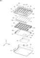
- FIG. 2 is an exploded perspective view of the electricity storage unit shown in FIG. 1 as viewed from below.
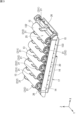
- FIG. 3 is a perspective view of an internal unit including a holder for holding an energy storage element and a substrate with a shielding member.
- FIG. 4 is a perspective view showing a state in which the electricity storage element is removed from the holder.
- FIG. 5 is an image diagram showing a cross section of a substrate.
- FIG. 6 is an enlarged view showing a part of the holder.
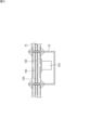
- FIG. 7 is a cross-sectional view showing a holder that holds the electricity storage element.
- FIG. 8 is an exploded perspective view of the electricity storage unit (second embodiment).
- FIG. 9 is a perspective view of a holder included in an electricity storage unit of the second embodiment.
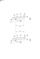
- FIG. 10 is an explanatory diagram of an A-type holding portion and a B-type holding portion.
- the conventional technology of the energy storage unit includes a lower holder for placing the energy storage element and an upper holder connected to the lower holder as components for holding the energy storage element (FIG. 11 of Patent Document 1).
- an upper cover and a lower cover are required to cover the holder unit consisting of the lower holder and the upper holder from above and below, which increases the size of the energy storage unit and the number of components.
- Patent Document 1 Figure 2 of Patent Document 1
- the invention disclosed in Patent Document 1 does not have an upper holder, and multiple energy storage elements are held only by the lower holder. This makes the energy storage unit more compact.
- the lower holder on which the energy storage elements are placed has multiple holding parts that sandwich the energy storage elements.
- the energy storage unit vibrates, or if the energy storage unit is used in a position in which the energy storage elements are lower than the lower holder, there is a possibility that the energy storage elements will come off the holder against the clamping force of the holding parts.
- the present disclosure therefore aims to provide an energy storage unit that can improve the function of holding energy storage elements without increasing the number of components.
- the energy storage unit of the present disclosure comprises a plurality of energy storage elements, a holder that holds the plurality of energy storage elements in a line, a first cover that covers the holder from the installation side of the energy storage elements, and a second cover that is integral with the first cover and accommodates the holder between the first cover and the holder, wherein the holder has a plurality of elastically deformable holding portions that sandwich the energy storage elements, and a first seat portion that is located between the holding portions that sandwich the energy storage elements and contacts the energy storage elements, and the first cover has a second seat portion that is located on the opposite side to the first seat portion and is capable of contacting or is in contact with the energy storage elements when covering the holder.
- the energy storage element is supported in the holder from three directions by the multiple holding portions and the first seat portion. If the energy storage element attempts to displace in a direction other than the three directions, i.e., toward the first cover, the displacement is restricted by the second seat portion of the first cover, and the energy storage element does not come off the holder.
- the function of holding the energy storage element is improved without increasing the number of parts.
- the second seat when the first cover covers the holder, the second seat is in contact with or in close proximity to the energy storage element.
- the second seat when the first cover covers the holder, the second seat is in a state where it is in contact with the electric storage element, and the second seat is capable of contacting the electric storage element.
- the electric storage element held by the holder starts to be displaced toward the first cover, the electric storage element comes into contact with the second seat, and the displacement is limited by the second seat.
- the second seat portion contacts the storage element, and the second seat portion or a portion surrounding the second seat portion elastically deforms.
- the first cover covers the holder the second seat portion comes into contact with the electricity storage element, and further, the second seat portion presses the electricity storage element.
- the second seat has a contact surface capable of contacting an outer peripheral surface of the energy storage element, and the exterior surface of the first cover opposite the surface on which the second seat is formed has a first surface located opposite the contact surface and a second surface located opposite the surface other than the contact surface, and the first surface and the second surface are arranged along the same plane.
- the exterior surface on the opposite side thereof has a flat shape.
- the second seat portion has a thickness and is therefore highly rigid.
- the plurality of holding sections include an A-type holding section and a B-type holding section having a greater force in the direction of clamping the energy storage element than the A-type holding section.
- the force in the direction of clamping the energy storage element is greater in the B-type holding portion than in the A-type holding portion.
- the force of a specific holding portion may be smaller than the force of other holding portions.
- the specific holding portion may be a B-type holding portion. This makes it possible to increase the force of the specific holding portion, for example, to be equal to the force of the other holding portions.
- the holder has a base portion having the first seat portion and on which the multiple energy storage elements are arranged in a row, and a multiple number of holding portions extending in a direction from the base portion toward the first cover, the holding portions having contact portions that contact the energy storage elements from the first cover side, the A-type holding portion having a first dimension as the dimension from the contact portion to the base portion, and the B-type holding portion having a second dimension from the contact portion to the base portion that is smaller than the first dimension.
- the force in the direction in which the B-type holding portion sandwiches the energy storage element becomes large.
- the storage unit of any one of (1) to (6) further includes a substrate located on the second cover side of the holder, and a shielding member covering electronic components mounted on a surface of the substrate on the second cover side, the substrate being a multilayer substrate having a shielding layer, and the shielding member covering the electronic components from the second cover side.
- the shielding member shields from the second cover side against the electronic components mounted on the board.
- the shielding layer of the board shields from the electronic components from the first cover side.
- a separate shielding member is not required on the first cover side. In other words, a separate shielding member is not required between the first cover and the multiple energy storage elements held in the holder.
- the storage unit of any one of (1) to (6) further includes a substrate located on the second cover side of the holder, and a shielding member covering electronic components mounted on a surface of the substrate on the first cover side, the substrate being a multilayer substrate having a shielding layer, and the shielding member covering the electronic components from the first cover side.
- the shielding member shields the electronic components mounted on the board from the first cover side.
- the shielding layer of the board shields the electronic components from the second cover side. No separate shielding member is required between the first cover and the multiple energy storage elements held in the holder.
- an energy storage unit is obtained in which the second seat portion of the first cover faces the energy storage elements, and even if the energy storage elements attempt to displace in a direction toward the first cover, the second seat portion limits the displacement of the energy storage elements.
- the energy storage element has a cylindrical shape
- the second seat portion has a contact surface having a cross-sectional arc shape that follows the cylindrical shape. According to this configuration, when the electricity storage unit attempts to be displaced against the holding portion, the second seat portion can suppress the displacement.
- Fig. 1 is a perspective view showing one embodiment of a power storage unit.
- Fig. 2 is an exploded perspective view of the power storage unit shown in Fig. 1 as seen from below.
- the power storage unit 10 is mounted on, for example, an automobile and used as an auxiliary power source.
- the power storage unit 10 supplies power to electrical equipment when an abnormality occurs in the automobile battery.
- the energy storage unit 10 includes a first cover 11 , a second cover 12 , a plurality of energy storage elements 13 , a holder 14 , a substrate 15 , and a shield member 16 .
- the storage element 13 is, for example, a capacitor such as an electric double layer capacitor.
- the storage element 13 may be a battery such as a lithium ion battery.
- the shape of the storage element 13 is not particularly limited, but the storage element 13 has a cylindrical element body 132 and a terminal 133 extending from the element body 132.
- the terminal 133 is electrically connected to the substrate 15. In the case of the form shown in FIG. 2, six storage elements 13 are lined up in one direction and held by the holder 14, but the number of storage elements 13 is not limited.
- the orientation of the energy storage unit 10 will now be described.
- the direction in which the multiple energy storage elements 13 are arranged in the holder 14 (the one direction) is defined as the "arrangement direction”.
- the axial direction of the cylindrical energy storage elements 13 held in the holder 14 is defined as the "width direction”.
- the direction perpendicular to both the arrangement direction and the width direction is defined as the "up-down direction”.
- the arrangement direction is indicated by an arrow X
- the width direction is indicated by an arrow Y
- the up-down direction is indicated by an arrow Z.
- the side indicated by the arrow is defined as the "first side,” and the opposite side is defined as the "second side.”
- the side indicated by the arrow in the up-down direction is defined as the "upper side” and the opposite side is defined as the "lower side”.
- the first cover 11 is the upper cover and the second cover 12 is the lower cover.
- the holder 14 holds the multiple energy storage elements 13 on its upper side.
- the "upper and lower directions” are directions defined for convenience in order to explain the configuration of the energy storage unit 10, and do not necessarily have to coincide with the vertical upper and lower directions when the energy storage unit 10 is installed in an apparatus. There is a case where the energy storage unit 10 is used in a position where the energy storage element 13 is lower than the holder 14, which is opposite to the cases in Figs. 1 and 2 .
- First cover 11 covers holder 14 from the upper side, which is the side on which energy storage elements 13 are installed.
- First cover 11 is made of insulating resin, and is integrally molded by injection molding.
- the second cover 12 is integrated with the first cover 11, and accommodates a holder 14 that holds the energy storage element 13, and a substrate 15 with a shielding member 16 between the second cover 12 and the first cover 11.
- the second cover 12 is made of insulating resin, and is integrally molded by injection molding.
- the second cover 12, together with the first cover 11, constitutes an exterior member of the energy storage unit 10.
- the second cover 12 has a shape that opens upward and includes one bottom wall 51 and four second side walls 52.
- the bottom wall 51 faces the substrate 15.
- the first cover 11 has a plurality of first engagement portions 115.
- the second cover 12 has a plurality of second engagement portions 125. The first engagement portions 115 and the second engagement portions 125 are engaged with each other, whereby the first cover 11 and the second cover 12 are joined together and do not shift relative to each other.
- the holder 14 holds multiple energy storage elements 13 lined up in the array direction.
- the holder 14 is made of insulating resin and is molded as a single unit by injection molding.
- the holder 14 holds the energy storage elements 13 with their upper sides exposed (see Figure 3).
- Figure 3 is a perspective view of the holder 14 that holds the energy storage elements 13, and the internal unit 17 that includes a substrate 15 with a shielding member 16.
- Figure 4 is a perspective view showing the energy storage elements 13 removed from the holder 14.
- the board 15 is located below the holder 14.
- the terminals 133 of the storage elements 13 are electrically connected to the printed wiring of the board 15.
- the board 15 has a control circuit that controls the charging and discharging of the multiple storage elements 13.
- the board 15 has a connector portion 156 that electrically connects the control circuit to external wiring (not shown) (see FIG. 2). Power output from the multiple storage elements 13 is supplied to the external wiring via the connector portion 156.
- Electronic components 153 are mounted on the board 15.
- the electronic components 153 include components that give electrical noise to the outside or components that are easily affected by electrical noise from the outside.
- Such electronic components 153 that require noise countermeasures are mounted on a surface 152 on the second cover 12 side, which is the underside of the board 15.
- the substrate 15 is a multi-layer substrate, and has a shield layer 154 as an intermediate layer.
- the shield layer 154 has a metal film 155.
- the metal film 155 is provided in an area that at least covers an area in which the electronic components 153 that require noise countermeasures are provided.
- the shielding member 16 is made of metal.
- the shielding member 16 functions as a shield for protecting against noise.
- the shielding member 16 has a box shape that opens on the side of the substrate 15.
- the shielding member 16 is attached to the substrate 15 by, for example, soldering.
- the shielding member 16 shown in FIG. 5 covers the electronic components 153 from below.
- the substrate 15 is attached to the holder 14 by, for example, a screw 61.
- the holder 14 is attached to the first cover 11 by, for example, a screw 62.
- the first cover 11 and the second cover 12 accommodate the internal unit 17 therein.
- the first cover 11 and the second cover 12 are members located on the outermost sides.
- the holder 14 (see Figures 3 and 4) has one base portion 20 and multiple holding portions 21.
- the base portion 20 is a portion on which multiple energy storage elements 13 are placed in a line.
- the holding portions 21 are provided extending upward from each portion of the base portion 20.
- the holding portions 21 are located on a first side (right side in Figure 3) in the arrangement direction and a second side (left side in Figure 3) in the arrangement direction, sandwiching the energy storage element 13 therebetween.
- the holding portions 21 are elastically deformable claw-shaped portions that sandwich the energy storage element 13 from both the first and second sides in the arrangement direction.
- the base portion 20 (see FIG. 4) has the same number of first seat portions 31 as the storage elements 13, one more frame portion 26 than the storage elements 13, and two outer frame portions 27.
- the two outer frame portions 27 are located on both sides of the holder 14 in the width direction, and are side walls that are long in the arrangement direction. Between the two outer frame portions 27, the frame portion 26 and the first seat portion 31 are alternately located along the arrangement direction.
- Figure 6 is an enlarged view showing a portion of the holder 14.
- Two frame portions 26 adjacent to each other in the arrangement direction and one first seat portion 31 located between these two frame portions 26 form a recess 25 that is recessed downward and elongated in the width direction.
- the lower half of the energy storage element 13 is housed in the recess 25.
- the recess 25 has a cross-sectional arc shape that follows the cylindrical shape.
- the first seat portion 31 has a shape that is long in the width direction and is connected to each of the two outer frame portions 27, and serves as a lower wall of the recess 25.
- the first seat portion 31 has a circular arc shape in cross section.
- the frame portion 26 has a frame main body portion 261 that is long in the width direction and is connected to each of the two outer frame portions 27, and a plurality of frame side portions 262 that are spaced apart in the width direction.
- the frame side portions 262 have an arc-shaped cross section and form side walls of the recess 25.
- the frame side portions 262 are continuous with the first seat portion 31.
- the frame side portions 262 come into contact with the energy storage elements 13 in the arrangement direction.
- the frame body 261 (frame 26) has cutouts 29 spaced apart in the width direction.
- the retaining portions 21 are located in the cutouts 29.
- the retaining portions 21 extend upward from the frame body 261, which is part of the frame 26.
- Figure 7 is a cross-sectional view showing the holder 14 holding the energy storage element 13.
- Figure 7 shows the state in which the first cover 11 and the second cover 12 (not shown) are joined.
- the first seat 31 contacts the energy storage element 13 from below.
- the first seat 31 is located between the holding part 21 on the first side in the arrangement direction and the holding part 21 on the second side in the arrangement direction, sandwiching one energy storage element 13.
- the first seat 31 has a first contact surface 311 with a cross-sectional arc shape that follows the cylindrical shape of the energy storage element 13.
- the storage element 13 is held by the holder 14 while placed on the first seat 31.
- the holding portion 21 on the first side in the arrangement direction contacts one storage element 13 placed on the first seat 31, and the holding portion 21 on the second side in the arrangement direction contacts one storage element 13 placed on the first seat 31.
- the holding portions 21 on both sides in the arrangement direction sandwich one storage element 13 placed on the first seat 31.
- the holding portion 21 on the first side in the arrangement direction and the holding portion 21 on the second side in the arrangement direction that sandwich one storage element 13 are at different positions in the width direction (see Figure 3).
- the holding portion 21 that contacts the energy storage element 13 from the first side in the arrangement direction (the right side in FIGS. 3 and 7 ) is referred to as the “first holding portion 211.”
- the holding portion 21 that contacts the energy storage element 13 from the second side in the arrangement direction (the left side in FIGS. 3 and 7 ) is referred to as the “second holding portion 212.”
- one energy storage element 13 is sandwiched from both sides in the arrangement direction by one first holding portion 211 and two second holding portions 212.
- One energy storage element 13 is held by the holder 14 at three points. Note that the number of holding portions 21 that sandwich one energy storage element 13 from both sides is not limited to three and can be changed.
- the holding portion 21 holds the energy storage element 13 in the recess 25 by coming into contact with the energy storage element 13 placed on the first seat portion 31.
- one holding portion 21 is provided on the frame portion 26 located on the first side in the arrangement direction (right side in Figures 3 and 4).
- Two holding portions 21 are provided on the frame portion 26 located on the second side in the arrangement direction (left side in Figures 3 and 4).
- Three holding portions 21 are provided on each of the other frame portions 26. Note that the number of holding portions 21 provided on one frame portion 26 is not limited.
- Each holding portion 21 has a pillar portion 23, a guide portion 24, and a contact portion 22.
- the pillar portion 23 is a portion that extends upward from the frame main body portion 261.
- the pillar portion 23 (holding portion 21) has a cantilever shape with the frame main body portion 261 side as the fixed end.
- the guide portion 24 is provided at the tip of the holding portion 21.
- the guide portion 24 guides the energy storage element 13 when the energy storage element 13 is placed on the first seat portion 31.
- the guide portion 24 has an inclined surface 241.
- the inclined surface 241 of the guide portion 24 of the first holding portion 211 inclines toward the first side in the arrangement direction as it advances upward.
- the inclined surface 241 of the guide portion 24 of the second holding portion 212 inclines toward the second side in the arrangement direction as it advances upward. In other words, the inclined surface 241 inclines away from the center of the energy storage element 13 guided by the guide portion 24 as it advances upward.
- the contact portion 22 comes into contact with the energy storage element 13 placed on the first seat portion 31.
- the contact portion 22 is located below the guide portion 24.
- the contact portion 22 comes into contact with the energy storage element 13 from the first cover 11 side, which is the upper side.
- the holding portion 21 is slightly elastically deformed on the side opposite the energy storage element 13.
- the first holding portion 211 is slightly elastically deformed toward the first side in the arrangement direction
- the second holding portion 212 is slightly elastically deformed toward the second side in the arrangement direction. Due to the reaction force (elastic restoring force) of the elastically deforming holding portion 21, the energy storage element 13 is sandwiched between the holding portions 21 on the first and second sides in the arrangement direction.
- a single energy storage element 13 placed on a single first seat 31 is sandwiched between the first retaining portion 211 and the second retaining portion 212 on both sides in the arrangement direction, and is in contact with the first seat 31.
- the energy storage element 13 is supported from three directions by the retaining portions 21 on both sides in the arrangement direction and the first seat 31 on the lower side.
- the holding portion 21 when the energy storage element 13 is attached to the holder 14 will be described.
- the energy storage element 13 is brought relatively close to the first seat 31 in the vertical direction and comes into contact with the guide portion 24.
- the energy storage element 13 slides downward along the inclined surface 241, pushing the guide portion 24 outward in both sides in the arrangement direction.
- the holding portions 21 on both sides are elastically deformed in both sides in the arrangement direction.
- the apex P2 of the energy storage element 13 which is the widest in the arrangement direction, passes over the guide portion 24 and the contact portion 22 downward, the holding portion 21 reduces the amount of deformation by the elastic restoring force.
- the contact portion 22 comes into contact with the outer peripheral surface 131 of the energy storage element 13 from above, and presses the energy storage element 13 against the first seat 31. In this manner, the energy storage element 13 is attached to the holder 14.
- the first cover 11 has one top wall 41 and four first side walls 42, and has a shape that opens downward.
- the top wall 41 is a portion that faces the multiple energy storage elements 13 held in the holder 14.
- the first side walls 42 are portions that cover the holder 14 that holds the multiple energy storage elements 13 from both sides in the arrangement direction and both sides in the width direction.
- the upper wall 41 has the same number of second seats 32 as the energy storage elements 13.
- the multiple second seats 32 are arranged side by side in the arrangement direction.
- the second seats 32 are portions that have a long groove in the width direction.
- the second seats 32 have an upwardly concave shape.
- the energy storage elements 13 have a cylindrical shape.
- the second seats 32 have a second contact surface 321 that has a cross-sectional arc shape that follows the cylindrical shape.
- the first cover 11 When the first cover 11 is integrated with the second cover 12, the first cover 11 covers the holder 14 that holds multiple energy storage elements 13 (hereinafter, this state is referred to as the "assembled state"; see Figure 7).
- the second seat 32 In the assembled state, the second seat 32 is located on the upper side, opposite the first seat 31 located below. When the first cover 11 and the second cover 12 are joined together, one second seat 32 is placed over one energy storage element 13.
- the second contact surface 321 can come into contact with the outer circumferential surface 131 of the energy storage element 13. That is, in the assembled state, the second seat portion 32 is in contact with or in close proximity to the energy storage element 13. In other words, in the assembled state, the second seat portion 32 is in a state where it is either in contact with or not in contact with the energy storage element 13. When the energy storage element 13 held by the holder 14 starts to displace upward toward the first cover 11, it comes into contact with the second seat portion 32, and the displacement is limited by the second seat portion 32. In this manner, in the assembled state, the second seat portion 32 is capable of coming into contact with the energy storage element 13.
- the second seat 32 and its surrounding portion 33 of the first cover 11 do not elastically deform in the assembled state. It is easy to set the positional relationship between the second seat 32 and the energy storage element 13 without increasing the dimensional accuracy of the manufacture of the first cover 11 and the holder 14. In other words, in the assembled state, if the second seat 32 is in contact with or close to the energy storage element 13, even if a dimensional error occurs in the first cover 11 and the holder 14, the dimensional error is unlikely to affect the state in which the energy storage element 13 is sandwiched between the first seat 31 and the second seat 32 from above and below.
- the vertical positional relationship between the second seat portion 32 and the energy storage element 13 may be other.
- the second seat portion 32 in the assembled state, the second seat portion 32 may be in contact with the energy storage element 13, and the second seat portion 32 or a portion 33 surrounding the second seat portion 32 may be configured to elastically deform.
- the second seat portion 32 in the assembled state, the second seat portion 32 is in contact with the energy storage element 13, and further, the second seat portion 32 presses the energy storage element 13.
- the second seat portion 32 of the first cover 11 is capable of contacting or is in contact with the energy storage element 13 in the assembled state.
- the upper wall 41 of the first cover 11 has a forming surface 112 of the second seat portion 32.
- the upper wall 41 has an exterior surface 111 opposite the forming surface 112 (see FIG. 1).
- the forming surface 112, which is the lower surface, has an uneven shape because the second seat portion 32 is formed thereon.
- the exterior surface 111 which is the upper surface, has a flat shape.
- the shape of the upper wall 41 will be further explained with reference to FIG.
- the forming surface 112 has a second contact surface 321 and a surface 322 other than the second contact surface 321 .
- the exterior surface 111 has a first surface 113 located on the opposite side (upper side) of the second contact surface 321 , and a second surface 114 located on the opposite side (upper side) of a surface 322 other than the second contact surface 321 .
- the first surface 113 and the second surface 114 are provided along the same plane.
- the exterior surface 111 on the opposite side has a flat shape.
- the second seat 32 has a thickness in the vertical direction and is more rigid than the other parts than the second seat 32. Even if the energy storage element 13 is displaced due to vibration or the like and presses the second seat 32, the second seat 32 and its surrounding part 33 do not easily deform elastically, making it possible to hold down the energy storage element 13.
- the exterior surface 111 is not necessarily a flat surface, and although not shown, may be an uneven surface similar to the forming surface 112.
- the thickness of the second seat portion 32 may be the same as the thickness of the portion other than the second seat portion 32, and therefore the first surface 113 may be a surface that is more recessed than the second surface 114.
- the energy storage element 13 is supported in three directions by the multiple holding portions 21 and the first seat portion 31 in the holder 14 (see FIG. 7 ). If the energy storage element 13 attempts to displace in a direction other than the three directions, that is, in the upward direction toward the first cover 11, the displacement is limited by the second seat portion 32 of the first cover 11, and the energy storage element 13 does not come off the holder 14.
- Fig. 8 is an exploded perspective view of the energy storage unit 10.
- the energy storage unit 10 shown in Fig. 8 has a first cover 11, a second cover 12, a plurality of energy storage elements 13, a holder 14, a substrate 15, and a shield member 16. In this respect, it is the same as the energy storage unit 10 (first embodiment) shown in Fig. 2. Below, differences will be mainly described.
- the second embodiment 8 is different from the first embodiment in that the functions of the first cover 11, the second cover 12, the holder 14, the substrate 15, and the shield member 16 are the same, but the forms of these are different and the number of the energy storage elements 13 is different. Note that the number of the energy storage elements 13 can be changed.
- the same components as those in the first embodiment are denoted by the same reference numerals.
- the components denoted by the same reference numerals may be the same as those in the first embodiment.
- the second cover 12 in the second embodiment is plate-shaped.
- the holder 14 has a plurality of legs 141 extending from the base 20 towards the board 15.
- the board 15 is located on the second cover 12 side, which is the lower side of the holder 14.
- An electronic component 153 that requires noise countermeasures is mounted on a surface 151 on the first cover 11 side, which is the upper side of the board 15.
- the shielding member 16 covers the electronic component 153 from the first cover 11 side, which is the upper side.
- the substrate 15 is a multi-layer substrate and has a shielding layer 154.
- the top-bottom arrangement of the substrate 15 and the shielding member 16 is reversed compared to the first embodiment (FIG. 5).
- the shielding member 16 is located between the substrate 15 and the base portion 20 of the holder 14.
- the holder 14 has legs 141, and a space for installing the shielding member 16 is provided between the base portion 20 and the substrate 15.
- FIG. 9 is a perspective view of a holder 14 of an electricity storage unit 10 according to the second embodiment.
- the holder 14 has one base portion 20 and multiple holding portions 21.
- the base portion 20 is a portion on which multiple energy storage elements 13 are arranged and placed.
- the holding portions 21 are provided extending upward from each portion of the base portion 20.
- the holding portions 21 are elastically deformable claw-shaped portions that hold the energy storage elements 13 from both the first side and the second side in the arrangement direction.
- the base portion 20 has first seat portions 31 in the same number as the storage elements 13 , frame portions 26 in the number of which is one more than the storage elements 13 , and two outer frame portions 27 .
- a recess 25 that is recessed downward and elongated in the width direction is formed by two frame portions 26 adjacent to each other in the arrangement direction and one first seat portion 31 located between the two frame portions 26.
- the lower half of the energy storage element 13 is housed in the recess 25.
- the first seat portion 31 has a shape that is long in the width direction and is connected to each of the two outer frame portions 27 , and forms a lower wall of the recess 25 .
- the frame portion 26 has a shape that is long in the width direction and is connected to each of the two outer frame portions 27.
- the holding portion 21 is provided by extending upward from a part of the frame portion 26. The number of holding portions 21 provided on one frame portion 26 differs from that of the first embodiment.
- the first seat 31 is located between the holding portion 21 on the first side in the arrangement direction and the holding portion 21 on the second side in the arrangement direction, sandwiching one energy storage element 13.
- the first seat 31 contacts the energy storage element 13 from below.
- the first seat 31 has a first contact surface 311 having a cross-sectional arc shape that follows the cylindrical shape of the energy storage element 13.
- one energy storage element 13 is sandwiched from both sides in the arrangement direction by three first holding portions 211 and three second holding portions 212.
- One energy storage element 13 is held by the holder 14 at six points. Note that the number of holding portions 21 that sandwich one energy storage element 13 from both sides is not limited to six and can be changed.
- the first cover 11 (see FIG. 8) has one top wall 41 and four first side walls 42, and has a shape that opens downwards.
- the top wall 41 is the part that faces the multiple storage elements 13 held in the holder 14.
- the top wall 41 has second seats 32 in the same number as the storage elements 13. In the assembled state in which the first cover 11 is integrated with the second cover 12, the second seats 32 are located on the upper side, opposite the first seats 31 located below.
- the configuration of the upper wall 41 of the first cover 11 in the second embodiment is the same as that in the first embodiment.
- the vertical positional relationship between the second seat portion 32 and the energy storage element 13 is the same as in the first embodiment ( FIG. 7 ), and the second seat portion 32 of the first cover 11 is contactable with or contacts the energy storage element 13 .
- the holding portion 21 of the holder 14 in each of the above-mentioned embodiments.
- the following describes the holder 14 in the first and second embodiments, and the holding portion 21 of the holder 14.
- the holding portion 21 is provided by extending upward from a part of the frame portion 26 of the holder 14 (the frame main body portion 261 in the case of the first embodiment shown in FIG. 6).
- the holding portions 21 (hereinafter referred to as “end holding portions 21") provided on the frame portion 26 at the end on the first side in the arrangement direction and the frame portion 26 at the end on the second side in the arrangement direction may have a smaller force (elastic force) in the direction of clamping the energy storage element 13 than the holding portion 21 (hereinafter referred to as "center holding portion 21") provided on the other central frame portion 26.
- the frame portion 26 at the end in the arrangement direction is a single plate-like member and has lower rigidity than the central frame portion 26, which results in a lower rigidity of the holding portions 21 as well.
- the holder 14 has a plurality of holding portions 21, and these plurality of holding portions 21 include a plurality of types of holding portions 21.
- the plurality of holding portions 21 have A-type holding portions 21 and B-type holding portions 21, and the force (elastic force) in the direction of sandwiching the energy storage element 13 is greater for the B-type holding portions 21 than for the A-type holding portions 21.
- the end holding portions 21 are B-type holding portions 21, and the central holding portion 21 is A-type holding portion 21.
- the A-type holding section 21 and the B-type holding section 21 each have the following configuration:
- Fig. 10 is an explanatory diagram of the A-type holding section 21 and the B-type holding section 21, with the A-type holding section 21 shown on the left side of Fig. 10 and the B-type holding section 21 shown on the right side.
- Each of the A-type holding portion 21 and the B-type holding portion 21 has a contact portion 22 that contacts the energy storage element 13 from above.
- the vertical positions of the contact portion 22 are the same for the A-type holding portion 21 and the B-type holding portion 21 so that the contact portion 22 contacts the energy storage element 13 at the same position in the vertical direction.
- the A-type holding portion 21 has a first dimension L1 as the dimension from the contact portion 22 (contact position P1 of the contact portion 22 with the energy storage element 13) to the base portion 20 (central frame portion 26).
- the B-type holding portion 21 has a second dimension L2 (L2 ⁇ L1) that is smaller than the first dimension L1 as the dimension from the contact portion 22 (contact position P2 of the contact portion 22 with the storage element 13) to the base portion 20 (end frame portion 26).
- the positions of the reference contact portion 22 are the same, but in order to make the first dimension L1 and the second dimension L2 different, the vertical positions of the base portion 20 (frame portion 26) which is the fixed end of each of the A-type holding portion 21 and the B-type holding portion 21 are made different.
- the frame portion 26 which is the base end of the B-type holding portion 21 is located higher than the frame portion 26 which is the base end of the A-type holding portion 21.
- the force in the direction of sandwiching the energy storage element 13 is greater in the B-type holding portion 21 than in the A-type holding portion 21. If all the holding portions 21 in one holder 14 have the same structure, as described above, the force of the end holding portions 21 will be smaller than the force of the central holding portion 21. Therefore, in each of the above embodiments, the end holding portions 21 are designated as B-type holding portions 21, and the central holding portion 21 is designated as A-type holding portion 212.
- the B-type holding portion 21, which is the end holding portion 21, exerts a greater force in the direction of sandwiching the energy storage element 13 than the A-type holding portion 21, which is the central holding portion 21, and the end holding portion 21 and the central holding portion 21 can have approximately the same rigidity, including the frame portion 26.
- the force with which the holding portion 21 holds the energy storage element 13 becomes uniform throughout the holder 14.
- the dimensions of the holding portion 21 may be made larger, or the holding portion 21 may have ribs (protrusions), although this is not shown.
- the energy storage unit 10 in each of the first embodiment (see FIG. 2 ) and the second embodiment (see FIG. 8 ) has a plurality of energy storage elements 13, a holder 14 that holds the plurality of energy storage elements 13 in an array, a first cover 11, and a second cover 12.
- the first cover 11 covers the holder 14 from the installation side of the energy storage elements 13.
- the second cover 12 is integrated with the first cover 11, and houses the holder 14 between itself and the first cover 11.
- the holder 14 has a plurality of elastically deformable holding portions 21 that sandwich the energy storage element 13 , and a first seat portion 31 that is located between the holding portions 21 that sandwich the energy storage element 13 and that comes into contact with the energy storage element 13 .
- the first cover 11 has a second seat portion 32. The second seat portion 32 is located on the opposite side to the first seat portion 31 when the first cover 11 covers the holder 14, and is capable of contacting or is in contact with the energy storage element 13.
- the energy storage element 13 is supported from three directions by the multiple holding portions 21 and the first seat portion 31. If the energy storage element 13 attempts to displace in a direction other than the three directions, i.e., in a direction toward the first cover 11, the displacement is restricted by the second seat portion 32 of the first cover 11, and the energy storage element 13 does not come off the holder 14.
- the first seat 31 (see FIG. 7) has a first contact surface 311 with a cross-sectional arc shape that conforms to the cylindrical shape of the energy storage element 13.
- the second seat 32 has a second contact surface 321 with a cross-sectional arc shape that conforms to the cylindrical shape of the energy storage element 13.
- the substrate 15 is located on the second cover 12 side (lower side) of the holder 14.
- the shielding member 16 covers the electronic components 153 mounted on the surface 152 on the second cover 12 side (lower side) of the substrate 15 from the second cover 12 side (lower side).
- the substrate 15 is a multilayer substrate having a shielding layer 154.
- the shielding member 16 shields the electronic components 153 mounted on the substrate 15 from the second cover 12 side (lower side).
- the shielding layer 154 of the substrate 15 shields the electronic components 153 from the first cover 11 side (upper side).
- a separate shielding member is not required on the first cover 11 side. In other words, a separate shielding member is not required between the first cover 11 and the multiple energy storage elements 13 held by the holder 14.
- the second seat portion 32 of the first cover 11 faces the storage element 13, and even if the storage element 13 attempts to displace in a direction toward the first cover 11, the displacement is restricted by the second seat portion 32, thereby obtaining a storage unit 10.
- the substrate 15 is located on the second cover 12 side (lower side) of the holder 14.
- the shielding member 16 covers the electronic components 153 mounted on the surface 151 on the first cover 11 side (upper side) of the substrate 15 from the first cover 11 side (upper side).
- the substrate 15 is a multilayer substrate having a shielding layer 154.
- the shielding member 16 shields the electronic components 153 mounted on the substrate 15 from the first cover 11 side (upper side).
- the shielding layer 154 of the substrate 15 shields the electronic components 153 from the second cover 12 side (lower side).
- No separate shielding member is required between the first cover 11 and the multiple energy storage elements 13 held by the holder 14.
- the second seat portion 32 of the first cover 11 faces the storage element 13, and even if the storage element 13 attempts to displace in a direction toward the first cover 11, the displacement is restricted by the second seat portion 32, thereby obtaining a storage unit 10.
- the first holding portion 211 and the second holding portion 212 provided on one frame portion 26 overlap at least partially with each other (the portion shown in area A1).
- the frame portion 26 can be made smaller in the arrangement direction, making it possible to further miniaturize the holder 14.
- one frame portion 26 is referred to as the "first frame portion 26" and the adjacent frame portion 26 is referred to as the "second frame portion 26.”
- first retaining portion 211 provided on the first frame portion 26 is positioned so as to overlap with the first retaining portion 211 provided on the second frame portion 26.
- second retaining portion 212 provided on the first frame portion 26 is positioned so as to overlap with the second retaining portion 212 provided on the second frame portion 26.
- the first holding portion 211 and the second holding portion 212 can be arranged repeatedly in a more compact manner.
- the width of each of the multiple frame portions 26 in the arrangement direction can be narrowed, making it possible to further reduce the size of the holder 14.
- FIG. 6 will be used as a representative example
- multiple second retaining portions 212 are provided spaced apart in the width direction.
- the first retaining portion 211 is located between two second retaining portions 212. That is, one of the two second retaining portions 212 is located on a first side in the width direction of the first retaining portion 211, and the other of the two second retaining portions 212 is located on a second side in the width direction of the first retaining portion 211.
- the multiple second holding portions 212 are positioned apart in the width direction with the first holding portion 211 sandwiched between them. Therefore, the energy storage element 13 is supported at two or more points that are apart in the width direction. This makes it possible to hold the energy storage element 13 more stably.
- the power storage unit 10 includes: The device has a plurality of storage elements 13 and a holder 14 that holds the plurality of storage elements 13 in an aligned manner, The holder 14 has a plurality of elastically deformable holding portions 21 that sandwich the energy storage element 13, and a first seat portion 31 that is located between the holding portions 21 that sandwich the energy storage element 13 and that comes into contact with the energy storage element 13, The plurality of holding portions 21 include an A-type holding portion 31 and a B-type holding portion 21 that exerts a greater force on the storage element 13 than the A-type holding portion 21 .
- the force in the direction of clamping the energy storage element 13 is greater in the B-type holding portion 21 than in the A-type holding portion 21.
- the force of a specific holding portion 21 may be smaller than the force of other holding portions 21.
- the specific holding portion 21 may be the B-type holding portion 21. This makes it possible to increase the force of the specific holding portion 21 in the direction of clamping the energy storage element 13.
- the holder 14 includes a base portion 20 having the first seat portion 31 and on which the plurality of energy storage elements 13 are arranged and placed, and a plurality of the holding portions 21 extending from the base portion 20 in a direction toward the first cover 11,
- the holding portion 21 has a contact portion 22 that comes into contact with the energy storage element 13 from the first cover 11 side
- the A-type holding portion 21 has a first dimension L1 as a dimension from the contact portion 22 to the base portion 20
- the B-type holding portion 21 has a second dimension L2, which is a dimension from the contact portion 22 to the base portion 20, that is smaller than the first dimension L1. According to the above-described configuration, the force in the direction in which B-type holding portion 21 pinches energy storage element 13 becomes large.
- the respective configurations of the other energy storage unit 10 are the same as the respective configurations of the energy storage unit 10 of the first form or the second form.
- the respective configurations of the energy storage unit 10 of each form can be applied to the other energy storage unit 10.
Landscapes
- Battery Mounting, Suspending (AREA)
- Electric Double-Layer Capacitors Or The Like (AREA)
Abstract
Description
特許文献1の場合、その従来技術として、蓄電ユニットは、蓄電素子を保持する部品として、蓄電素子を載せる下ホルダと、下ホルダと結合される上ホルダとを有する(特許文献1の図11)。この場合、下ホルダ及び上ホルダから成るホルダユニットを上下から覆う上カバー及び下カバーが必要となり、蓄電ユニットが大きくなり、また、部品数が増加する。
本開示の蓄電ユニットによれば、部品数を増やさなくても、蓄電素子を保持する機能を高めることが可能となる。
以下、本開示の実施形態の概要を列記して説明する。
(1)本開示の蓄電ユニットは、複数の蓄電素子と、前記複数の蓄電素子を並べて保持するホルダと、前記ホルダを前記蓄電素子の設置側から覆う第一カバーと、前記第一カバーと一体となり前記第一カバーとの間で前記ホルダを収容する第二カバーと、を有し、前記ホルダは、前記蓄電素子を挟む弾性変形可能な複数の保持部と、前記蓄電素子を挟む前記保持部の間に位置し前記蓄電素子に接触する第一座部と、を有し、前記第一カバーは、前記ホルダを覆った状態で、前記第一座部と反対側に位置し前記蓄電素子に接触可能である又は接触する第二座部を有する。
前記構成の場合、第一カバーがホルダを覆った状態で、第二座部は、蓄電素子に触れるか触れないかの状態となり、第二座部は、蓄電素子に接触可能となる。ホルダに保持される蓄電素子は、第一カバーに向かう側に変位し始めると、第二座部と接触し、その変位は第二座部により制限される。
前記構成の場合、第一カバーがホルダを覆った状態で、第二座部は、蓄電素子に接触し、さらに、第二座部は、蓄電素子を押す。
前記構成の場合、第一カバーのうち、第二座部の形成面は凹凸形状であっても、その反対側となる外装面は、平坦形状を有する。第二座部は、厚さを有し剛性が高くなる。
前記構成によれば、蓄電素子を挟む方向の力は、A型保持部よりもB型保持部の方が大きい。例えば、ホルダにおける保持部の形成位置によっては、特定の保持部の力が、他の保持部の力よりも小さくなる場合がある。この場合、前記特定の保持部をB型保持部とすればよい。これにより、前記特定の保持部の力は大きくなり、例えば、他の保持部の力と同等とすることが可能となる。
前記構成によれば、B型保持部が蓄電素子を挟む方向の力は、大きくなる。
前記構成によれば、シールド部材は、基板に実装されている電子部品に対して、第二カバー側からシールドする。基板のシールド層は、前記電子部品に対して、第一カバー側からシールドする。第一カバー側にシールド用の別部材は不要となる。つまり、ホルダに保持される複数の蓄電素子と、第一カバーとの間に、シールド用の別部材は不要となる。その結果、第一カバーが有する第二座部は、蓄電素子と対向し、蓄電素子は、第一カバーに向かう方向に変位しようとしても、その変位を第二座部が制限する蓄電ユニットが得られる。
前記構成によれば、シールド部材は、基板に実装されている電子部品に対して、第一カバー側からシールドする。基板のシールド層は、前記電子部品に対して、第二カバー側からシールドする。ホルダに保持される複数の蓄電素子と、第一カバーとの間に、シールド用の別部材は不要となる。その結果、第一カバーが有する第二座部は、蓄電素子と対向し、蓄電素子は、第一カバーに向かう方向に変位しようとしても、その変位を第二座部が制限する蓄電ユニットが得られる。
前記構成によれば、蓄電ユニットが前記保持部に抗して変位しようとすると、第二座部が、その変位を抑えることが可能となる。
以下、図面を参照して、本開示の実施形態の詳細を説明する。なお、以下に記載する実施形態の少なくとも一部を任意に組み合わせてもよい。
図1は、蓄電ユニットの実施の一形態を示す斜視図である。図2は、図1に示す蓄電ユニットを下から見た場合の分解斜視図である。蓄電ユニット10は、例えば自動車に搭載され、補助電源として用いられる。蓄電ユニット10は、自動車のバッテリに異常が生じた際に、電装品に電力を供給する。
蓄電ユニット10は、第一カバー11と、第二カバー12と、複数の蓄電素子13と、ホルダ14と、基板15と、シールド部材16とを有する。
ホルダ14において複数の蓄電素子13が並ぶ方向(前記一方向)が「配列方向」と定義される。ホルダ14に保持される円柱形状の蓄電素子13の軸方向が「幅方向」と定義される。配列方向と幅方向との双方に直交する方向が「上下方向」と定義される。
各図において、配列方向を矢印Xにより示し、幅方向を矢印Yにより示し、上下方向を矢印Zにより示す。配列方向(矢印X)、幅方向(矢印Y)及び上下方向(矢印Z)について、矢印が指す側が「第一側」と定義され、その反対側が「第二側」と定義される。
なお、「上下方向」は、蓄電ユニット10の構成を説明するために、便宜上に定義する方向であり、蓄電ユニット10が装置に設置された際の鉛直上下方向と一致しなくてもよい。図1及び図2の場合と反対に、蓄電素子13がホルダ14よりも下となるような姿勢で蓄電ユニット10が用いられる場合がある。
第二カバー12は、第一カバー11と一体となり、第一カバー11との間で、蓄電素子13を保持するホルダ14、及び、シールド部材16付きの基板15を収容する。第二カバー12は、絶縁性樹脂により構成されていて、射出成形により一体成型される。第二カバー12は、第一カバー11と共に、蓄電ユニット10の外装の部材となる。
第一カバー11は、複数の第一係合部115を有する。第二カバー12は、複数の第二係合部125を有する。第一係合部115と第二係合部125とが係合することで、第一カバー11と第二カバー12とは結合され、相互間で位置ずれしない。
シールド部材16は、金属により構成されている。シールド部材16は、ノイズから保護するためのシールドとして機能する。シールド部材16は、基板15側に開口する箱形状を有する。シールド部材16は、基板15に、例えば半田によって取り付けられる。図5に示すシールド部材16は、電子部品153を下側から覆う。
第一カバー11と第二カバー12とが結合されると、第一カバー11及び第二カバー12は、その内部において、前記内部ユニット17を収容する。蓄電ユニット10において、第一カバー11及び第二カバー12が最も外側に位置する部材となる。
ホルダ14は(図3及び図4参照)、一つのベース部20と、複数の保持部21とを有する。ベース部20は、複数の蓄電素子13を並べて載せる部分である。保持部21は、ベース部20の各部から上に延びて設けられている。保持部21は、蓄電素子13を挟んで配列方向の第一側(図3の右側)と配列方向の第二側(図3の左側)とに位置する。保持部21は、蓄電素子13を、配列方向の第一側及び第二側の両側から挟む弾性変形可能な爪状の部分である。
枠部26は、2つの外枠部27それぞれと繋がる幅方向に長い枠本体部261と、幅方向に間隔をあけて設けられている複数の枠側部262とを有する。枠側部262は、断面円弧形状を有し、凹部25の側壁となる。枠側部262は、第一座部31と連続する。枠側部262は、蓄電素子13に配列方向から接触する。
図3に示す形態の場合、一つの蓄電素子13は、1つの第一保持部211と、2つの第二保持部212とにより、配列方向の両側から挟まれた状態となる。一つの蓄電素子13は、3点でホルダ14に保持される。なお、一つの蓄電素子13を両側から挟む保持部21の数は、3つに限定されず、変更可能である。
蓄電素子13は、第一座部31に対して上下方向に相対的に近づけられ、案内部24に接触する。蓄電素子13は、傾斜面241に接触すると、その傾斜面241を下に向かって滑りながら、案内部24を配列方向の両側に押し広げる。これにより、両側の保持部21は、配列方向の両側に弾性変形する。蓄電素子13のうち配列方向の幅が最も広い幅方向の頂点P2が、案内部24及び接触部22を下側に越えると、保持部21は、弾性復元力によって、変形量を小さくする。この状態で、接触部22は、蓄電素子13の外周面131に対して上から接触し、蓄電素子13を第一座部31に押し付ける状態となる。このようにして、蓄電素子13は、ホルダ14に取り付けられる。
図2に示すように、第一カバー11は、1つの上壁41と、4つの第一側壁42とを有し、下に開口する形状を有する。上壁41は、ホルダ14に保持される複数の蓄電素子13と対向する部分である。第一側壁42は、複数の蓄電素子13を保持するホルダ14を、配列方向の両側、及び幅方向の両側から覆う部分である。
ホルダ14に保持される蓄電素子13が、第一カバー11に向かう上側に変位し始めると、第二座部32と接触し、その変位は第二座部32により制限される。このように、組み立て状態で、第二座部32は、蓄電素子13に接触可能となる。
形成面112は、第二接触面321と、第二接触面321以外の面322とを有する。
外装面111は、第二接触面321の反対側(上側)に位置する第一面113と、第二接触面321以外の面322の反対側(上側)に位置する第二面114とを有する。
これら第一面113と第二面114とは同一の面に沿って設けられている。
以上の構成を有する蓄電ユニット10によれば、ホルダ14において、蓄電素子13は、複数の保持部21と第一座部31とによって三方向から支持される(図7参照)。蓄電素子13は、前記三方向と異なる方向、つまり、第一カバー11に向かう上の方向に変位しようとすると、その変位は、第一カバー11が有する第二座部32により制限され、蓄電素子13はホルダ14から外れない。
図8は、蓄電ユニット10の分解斜視図である。図8に示す蓄電ユニット10は、第一カバー11と、第二カバー12と、複数の蓄電素子13と、ホルダ14と、基板15と、シールド部材16とを有する。この点は、図2に示す蓄電ユニット10(第一の形態)と同じである。以下、異なる点について主に説明する。
第二の形態において、第一の形態と同じ構成については、同じ符号が付されている。第二の形態において、同じ符号が付されている構成については、第一の形態の構成を採用することが可能である。
第二の形態において、ホルダ14は、ベース部20から基板15側に延びる複数の脚部141を有する。基板15は、ホルダ14の下側となる第二カバー12側に位置する。ノイズ対策が必要となる電子部品153は、基板15の上側となる第一カバー11側の面151に実装される。シールド部材16は、その電子部品153を、上側となる第一カバー11側から覆う。
第二の形態の場合(図8参照)、シールド部材16は、基板15と、ホルダ14のベース部20との間に位置する。このために、ホルダ14は、脚部141を有し、ベース部20と基板15との間に、シールド部材16の設置用スペースが設けられている。
ホルダ14は、一つのベース部20と、複数の保持部21とを有する。ベース部20は、複数の蓄電素子13を並べて載せる部分である。保持部21は、ベース部20の各部から上に延びて設けられている。保持部21は、蓄電素子13を、配列方向の第一側及び第二側の両側から挟む弾性変形可能な爪状の部分である。
ベース部20は、蓄電素子13と同数の第一座部31と、蓄電素子13よりも一つ多い数の枠部26と、2つの外枠部27とを有する。
第一座部31は、2つの外枠部27それぞれと繋がる幅方向に長い形状を有し、凹部25の下壁となる。
枠部26は、2つの外枠部27それぞれと繋がる幅方向に長い形状を有する。保持部21は、枠部26の一部から上に向かって延びて設けられている。
一つの枠部26に設けられる保持部21の数は、第一の形態と異なる。
第二の形態の場合(図9参照)、一つの蓄電素子13は、3つの第一保持部211と、3つの第二保持部212とにより、配列方向の両側から挟まれた状態となる。一つの蓄電素子13は、6点でホルダ14に保持される。なお、一つの蓄電素子13を両側から挟む保持部21の数は、6つに限定されず、変更可能である。
組み立て状態で、第二座部32と蓄電素子13との上下方向の位置関係は、第一の形態(図7)と同様であり、第一カバー11の第二座部32は、蓄電素子13に接触可能である又は接触する。
前記第一の形態及び前記第二の形態のホルダ14、並びに、そのホルダ14が有する保持部21について説明する。前記のとおり、保持部21は、ホルダ14が有する枠部26の一部(図6に示す第一の形態の場合、枠本体部261)から上に延びて設けられている。
そのために、前記各形態において、ホルダ14は、複数の保持部21を有するが、これら複数の保持部21に、複数種類の保持部21が含まれる。つまり、複数の保持部21は、A型保持部21と、B型保持部21とを有し、蓄電素子13を挟む方向の力(弾性力)は、A型保持部21よりもB型保持部21の方が大きい。端の保持部21がB型保持部21とされ、中央の保持部21がA型保持部21とされる。
A型保持部21及びB型保持部21それぞれは、蓄電素子13に対して、上側から接触する接触部22を有する。接触部22は、蓄電素子13に対して上下方向について同じ位置で接触するように、その接触部22の上下方向の位置は、A型保持部21とB型保持部21とで同じである。
B型保持部21は、接触部22(接触部22の蓄電素子13との接触位置P2)からベース部20(端の枠部26)までの寸法として、第一寸法L1よりも小さい第二寸法L2(L2<L1)を有する。
これにより、端の保持部21であるB型保持部21は、中央の保持部21であるA型保持部21よりも、蓄電素子13を挟む方向の力が大きくなり、端の保持部21と、中央の保持部21とで、枠部26を含めて剛性を同程度にすることできる。その結果、保持部21により蓄電素子13を保持する力が、ホルダ14の全体として均一となる。
以上のように、前記第一の形態(図2参照)及び前記第二の形態(図8参照)それぞれの蓄電ユニット10は、複数の蓄電素子13と、複数の蓄電素子13を並べて保持するホルダ14と、第一カバー11と、第二カバー12とを有する。第一カバー11は、ホルダ14を蓄電素子13の設置側から覆う。第二カバー12は、第一カバー11と一体となり、第一カバー11との間でホルダ14を収容する。
第一カバー11は、第二座部32を有する。第二座部32は、第一カバー11がホルダ14を覆った状態で、第一座部31と反対側に位置し、蓄電素子13に接触可能である又は接触する。
第一カバー11が、蓄電素子13がホルダ14から外れることを阻止する機能を有する。よって、部品数を増やさなくても、蓄電素子13を保持する機能が高まる。
その結果、第一カバー11が有する第二座部32は、蓄電素子13と対向し、蓄電素子13は、第一カバー11に向かう方向に変位しようとしても、その変位を第二座部32が制限する蓄電ユニット10が得られる。
その結果、第一カバー11が有する第二座部32は、蓄電素子13と対向し、蓄電素子13は、第一カバー11に向かう方向に変位しようとしても、その変位を第二座部32が制限する蓄電ユニット10が得られる。
前記第一の形態及び前記第二の形態それぞれにおける保持部21の配置について説明する。
ここで、前記特許文献1の場合、一つの枠部において、2つの保持部が窪みを介して対向して位置する(特許文献1の段落0038、図7及び図9)。
これに対し、前記各形態の場合(図6及び図9参照)一つの枠部26に設けられている第一保持部211及び第二保持部212は、配列方向に沿って見た場合に重複しない。すなわち、一つの枠部26において、第一保持部211が形成されている部分に第二保持部212は形成されず、第二保持部212が形成されている部分に第一保持部211は形成されない。
このように構成することで、枠部26を配列方向に小さくすることができ、ホルダ14を小型化することができる。その結果、蓄電ユニット10を小型化することが可能となる。
別の観点による蓄電ユニット10について説明する。なお、その蓄電ユニット10は、図1から図10に示されている。
<別の蓄電ユニット10>
蓄電ユニット10は、
複数の蓄電素子13と、前記複数の蓄電素子13を並べて保持するホルダ14と、を有し、
前記ホルダ14は、前記蓄電素子13を挟む弾性変形可能な複数の保持部21と、前記蓄電素子13を挟む前記保持部21の間に位置し前記蓄電素子13に接触する第一座部31と、を有し、
前記複数の保持部21は、A型保持部31と、前記蓄電素子13を挟む方向の力が前記A型保持部21よりも大きいB型保持部21と、を有する。
前記ホルダ14は、前記第一座部31を有し前記複数の蓄電素子13を並べて載せるベース部20と、前記ベース部20から前記第一カバー11に向かう方向に延びて設けられている複数の前記保持部21と、を有し、
前記保持部21は、前記蓄電素子13に対して前記第一カバー11側から接触する接触部22を有し、
前記A型保持部21は、前記接触部22から前記ベース部20までの寸法として、第一寸法L1を有し、
前記B型保持部21は、前記接触部22から前記ベース部20までの寸法として、前記第一寸法L1よりも小さい第二寸法L2を有する。
前記構成によれば、B型保持部21が蓄電素子13を挟む方向の力は、大きくなる。
前記実施形態は、すべての点で例示であって制限的なものではない。本発明の権利範囲は、前記実施形態ではなく請求の範囲によって示され、請求の範囲に記載された構成と均等の範囲内でのすべての変更を含む。
11 第一カバー
111 外装面
112 形成面
113 第一面
114 第二面
115 第一係合部
12 第二カバー
125 第二係合部
13 蓄電素子
131 外周面
132 素子本体
133 端子
14 ホルダ
141 脚部
15 基板
151 面
152 面
153 電子部品
154 シールド層
155 金属膜
156 コネクタ部
16 シールド部材
17 内部ユニット
20 ベース部
21 保持部
211 第一保持部
212 第二保持部
22 接触部
23 柱部
24 案内部
241 傾斜面
25 凹部
26 枠部
261 枠本体部
262 枠側部
27 外枠部
29 欠損部
31 第一座部
311 第一接触面
32 第二座部
321 第二接触面
322 面
33 周囲の部分
41 上壁
42 第一側壁
51 下壁
52 第二側壁
A1 領域
L1 寸法
L2 寸法
P2 頂点
Claims (9)
- 複数の蓄電素子と、
前記複数の蓄電素子を並べて保持するホルダと、
前記ホルダを前記蓄電素子の設置側から覆う第一カバーと、
前記第一カバーと一体となり前記第一カバーとの間で前記ホルダを収容する第二カバーと、
を有し、
前記ホルダは、
前記蓄電素子を挟む弾性変形可能な複数の保持部と、
前記蓄電素子を挟む前記保持部の間に位置し前記蓄電素子に接触する第一座部と、
を有し、
前記第一カバーは、
前記ホルダを覆った状態で、前記第一座部と反対側に位置し前記蓄電素子に接触可能である又は接触する第二座部を有する、
蓄電ユニット。 - 前記第一カバーが前記ホルダを覆った状態で、前記第二座部は、前記蓄電素子に接した状態又は近接した状態にある、
請求項1に記載の蓄電ユニット。 - 前記第一カバーが前記ホルダを覆った状態で、前記第二座部は、前記蓄電素子に接触し、前記第二座部又は前記第二座部の周囲の部分は弾性変形する、
請求項1に記載の蓄電ユニット。 - 前記第二座部は、前記蓄電素子の外周面に接触可能となる接触面を有し、
前記第一カバーのうちの、前記第二座部の形成面と反対側となる外装面は、
前記接触面の反対側に位置する第一面と、
前記接触面以外の面の反対側に位置する第二面と、を有し、
前記第一面と前記第二面とは同一の面に沿って設けられている、
請求項1から請求項3のいずれか一項に記載の蓄電ユニット。 - 前記複数の保持部は、
A型保持部と、
前記蓄電素子を挟む方向の力が前記A型保持部よりも大きいB型保持部と、
を有する、
請求項1から請求項4のいずれか一項に記載の蓄電ユニット。 - 前記ホルダは、
前記第一座部を有し前記複数の蓄電素子を並べて載せるベース部と、
前記ベース部から前記第一カバーに向かう方向に延びて設けられている複数の前記保持部と、
を有し、
前記保持部は、前記蓄電素子に対して前記第一カバー側から接触する接触部を有し、
前記A型保持部は、前記接触部から前記ベース部までの寸法として、第一寸法を有し、
前記B型保持部は、前記接触部から前記ベース部までの寸法として、前記第一寸法よりも小さい第二寸法を有する、
請求項5に記載の蓄電ユニット。 - 前記ホルダの前記第二カバー側に位置する基板と、
前記基板の前記第二カバー側の面に実装されている電子部品を覆うシールド部材と、
を有し、
前記基板は、シールド層を有する多層基板であり、
前記シールド部材は、前記電子部品を前記第二カバー側から覆う、
請求項1から請求項6のいずれか一項に記載の蓄電ユニット。 - 前記ホルダの前記第二カバー側に位置する基板と、
前記基板の前記第一カバー側の面に実装されている電子部品を覆うシールド部材と、
を有し、
前記基板は、シールド層を有する多層基板であり、
前記シールド部材は、前記電子部品を前記第一カバー側から覆う、
請求項1から請求項6のいずれか一項に記載の蓄電ユニット。 - 前記蓄電素子は、円柱形状を有し、
前記第二座部は、前記円柱形状に沿った断面円弧形状の接触面を有する、
請求項1から請求項8のいずれか一項に記載の蓄電ユニット。
Priority Applications (1)
| Application Number | Priority Date | Filing Date | Title |
|---|---|---|---|
| CN202480044966.7A CN121444195A (zh) | 2023-07-06 | 2024-06-24 | 蓄电单元 |
Applications Claiming Priority (2)
| Application Number | Priority Date | Filing Date | Title |
|---|---|---|---|
| JP2023111592A JP2025008944A (ja) | 2023-07-06 | 2023-07-06 | 蓄電ユニット |
| JP2023-111592 | 2023-07-06 |
Publications (1)
| Publication Number | Publication Date |
|---|---|
| WO2025009434A1 true WO2025009434A1 (ja) | 2025-01-09 |
Family
ID=94171999
Family Applications (1)
| Application Number | Title | Priority Date | Filing Date |
|---|---|---|---|
| PCT/JP2024/022910 Ceased WO2025009434A1 (ja) | 2023-07-06 | 2024-06-24 | 蓄電ユニット |
Country Status (3)
| Country | Link |
|---|---|
| JP (1) | JP2025008944A (ja) |
| CN (1) | CN121444195A (ja) |
| WO (1) | WO2025009434A1 (ja) |
Citations (7)
| Publication number | Priority date | Publication date | Assignee | Title |
|---|---|---|---|---|
| JPH06283885A (ja) * | 1993-03-25 | 1994-10-07 | Nippon Chemicon Corp | 回路基板及びその処理方法 |
| JPH10172527A (ja) * | 1996-12-17 | 1998-06-26 | Saitama Nippon Denki Kk | 電池パック固定構造 |
| JP2007088412A (ja) * | 2005-08-22 | 2007-04-05 | Matsushita Electric Ind Co Ltd | キャパシタユニット |
| JP2016081795A (ja) * | 2014-10-20 | 2016-05-16 | パナソニックIpマネジメント株式会社 | 蓄電ユニット |
| US20170374758A1 (en) * | 2015-03-20 | 2017-12-28 | Hanon Systems | Device for radiating heat of capacitor of an inverter in an electric compressor |
| WO2018216728A1 (ja) * | 2017-05-24 | 2018-11-29 | パナソニックIpマネジメント株式会社 | 蓄電モジュールおよび蓄電ユニット |
| JP2020198191A (ja) * | 2019-05-31 | 2020-12-10 | 東洋システム株式会社 | 電池パック |
-
2023
- 2023-07-06 JP JP2023111592A patent/JP2025008944A/ja active Pending
-
2024
- 2024-06-24 CN CN202480044966.7A patent/CN121444195A/zh active Pending
- 2024-06-24 WO PCT/JP2024/022910 patent/WO2025009434A1/ja not_active Ceased
Patent Citations (7)
| Publication number | Priority date | Publication date | Assignee | Title |
|---|---|---|---|---|
| JPH06283885A (ja) * | 1993-03-25 | 1994-10-07 | Nippon Chemicon Corp | 回路基板及びその処理方法 |
| JPH10172527A (ja) * | 1996-12-17 | 1998-06-26 | Saitama Nippon Denki Kk | 電池パック固定構造 |
| JP2007088412A (ja) * | 2005-08-22 | 2007-04-05 | Matsushita Electric Ind Co Ltd | キャパシタユニット |
| JP2016081795A (ja) * | 2014-10-20 | 2016-05-16 | パナソニックIpマネジメント株式会社 | 蓄電ユニット |
| US20170374758A1 (en) * | 2015-03-20 | 2017-12-28 | Hanon Systems | Device for radiating heat of capacitor of an inverter in an electric compressor |
| WO2018216728A1 (ja) * | 2017-05-24 | 2018-11-29 | パナソニックIpマネジメント株式会社 | 蓄電モジュールおよび蓄電ユニット |
| JP2020198191A (ja) * | 2019-05-31 | 2020-12-10 | 東洋システム株式会社 | 電池パック |
Also Published As
| Publication number | Publication date |
|---|---|
| JP2025008944A (ja) | 2025-01-20 |
| CN121444195A (zh) | 2026-01-30 |
Similar Documents
| Publication | Publication Date | Title |
|---|---|---|
| US7369415B2 (en) | Multilayer electronic circuit device | |
| US11349240B2 (en) | Floating connector and electronic device | |
| JP5212019B2 (ja) | 電気接続箱および該電気接続箱の組立方法 | |
| CN115332730B (zh) | 汇流条模块 | |
| US11322870B2 (en) | Connector and electronic device | |
| CN115332731B (zh) | 汇流条模块 | |
| CN113015658B (zh) | 电气连接箱 | |
| CN115332732B (zh) | 汇流条模块 | |
| CN104067402A (zh) | 端子固定结构及使用该端子固定结构的供电装置 | |
| WO2013054727A1 (ja) | 電源制御装置 | |
| CN114830453B (zh) | 连接器及电子设备 | |
| JP2025008944A (ja) | 蓄電ユニット | |
| US20240339732A1 (en) | Bus bar module | |
| WO2023166949A1 (ja) | ホルダ及び蓄電ユニット | |
| WO2023166954A1 (ja) | 蓄電ユニット | |
| JP2024090536A (ja) | 配線モジュール | |
| JP7769883B2 (ja) | 配線モジュール | |
| KR20230021935A (ko) | 제어 장치 | |
| JP7687220B2 (ja) | 電子装置 | |
| KR102885314B1 (ko) | Bms 어셈블리, 이를 포함하는 배터리 모듈 및 배터리 팩 | |
| JP7764271B2 (ja) | コネクタ及び組立体 | |
| US20250246827A1 (en) | Wire harness | |
| US20250374487A1 (en) | Electrical connection unit | |
| US20260100523A1 (en) | Electrical connection unit | |
| JP7739826B2 (ja) | 電力変換装置 |
Legal Events
| Date | Code | Title | Description |
|---|---|---|---|
| 121 | Ep: the epo has been informed by wipo that ep was designated in this application |
Ref document number: 24835947 Country of ref document: EP Kind code of ref document: A1 |
|
| DPE2 | Request for preliminary examination filed before expiration of 19th month from priority date (pct application filed from 20040101) | ||
| WWE | Wipo information: entry into national phase |
Ref document number: 202617001321 Country of ref document: IN |
|
| WWP | Wipo information: published in national office |
Ref document number: 202617001321 Country of ref document: IN |
|
| NENP | Non-entry into the national phase |
Ref country code: DE |
|
| 122 | Ep: pct application non-entry in european phase |
Ref document number: 24835947 Country of ref document: EP Kind code of ref document: A1 |