WO2025009404A1 - 情報処理装置、情報処理システム、モデル決定方法、およびモデル決定プログラム - Google Patents
情報処理装置、情報処理システム、モデル決定方法、およびモデル決定プログラム Download PDFInfo
- Publication number
- WO2025009404A1 WO2025009404A1 PCT/JP2024/022362 JP2024022362W WO2025009404A1 WO 2025009404 A1 WO2025009404 A1 WO 2025009404A1 JP 2024022362 W JP2024022362 W JP 2024022362W WO 2025009404 A1 WO2025009404 A1 WO 2025009404A1
- Authority
- WO
- WIPO (PCT)
- Prior art keywords
- equipment
- prediction
- model
- information processing
- target
- Prior art date
- Legal status (The legal status is an assumption and is not a legal conclusion. Google has not performed a legal analysis and makes no representation as to the accuracy of the status listed.)
- Ceased
Links
Images




Classifications
-
- G—PHYSICS
- G05—CONTROLLING; REGULATING
- G05B—CONTROL OR REGULATING SYSTEMS IN GENERAL; FUNCTIONAL ELEMENTS OF SUCH SYSTEMS; MONITORING OR TESTING ARRANGEMENTS FOR SUCH SYSTEMS OR ELEMENTS
- G05B23/00—Testing or monitoring of control systems or parts thereof
- G05B23/02—Electric testing or monitoring
-
- G—PHYSICS
- G06—COMPUTING OR CALCULATING; COUNTING
- G06N—COMPUTING ARRANGEMENTS BASED ON SPECIFIC COMPUTATIONAL MODELS
- G06N20/00—Machine learning
Definitions
- the present invention relates to an information processing system that performs control according to the results of predictions made using a prediction model.
- Patent Document 1 describes how, in a waste treatment plant facility, a predicted value for the amount of steam generated is calculated using a learning model that predicts the amount of steam generated after a specified time. It also describes how a primary combustion air damper is controlled by applying an operating value that reduces the difference between the predicted amount of steam generated and the target amount of steam generated to zero.
- a waste treatment plant may be equipped with multiple incinerators.
- the characteristics of each incinerator may differ, and so there is a risk that prediction accuracy will decrease if the same learning model is used to make predictions for each incinerator.
- One aspect of the present invention aims to realize an information processing device or the like that is capable of determining an appropriate prediction model for the target equipment to be controlled among multiple pieces of equipment.
- an information processing device includes a target identification unit that identifies, as target equipment, equipment to be controlled from among a predetermined number of pieces of equipment, and a model determination unit that determines, for each of the plurality of pieces of equipment, a prediction model to be used for predicting a predetermined event related to the control of the equipment, based on model allocation information that assigns the prediction model to be used for predicting the event in the target equipment.
- an information processing system includes an information processing device that determines a prediction model to be used to predict events in a target piece of equipment to be controlled among a plurality of pieces of equipment based on model allocation information that assigns, to each piece of equipment, a prediction model to be used to predict a predetermined event related to the control of the equipment; a prediction device that predicts the event in the target equipment using the prediction model determined by the information processing device; and a control content determination device that determines control content for the target equipment based on the prediction result by the prediction device.
- a model determination method is a model determination method executed by one or more information processing devices, and includes a target identification step of identifying equipment to be controlled from among a predetermined number of pieces of equipment as target equipment, and a model determination step of determining, for each of the plurality of pieces of equipment, a prediction model to be used for predicting a predetermined event related to the control of the equipment, based on model allocation information that assigns the prediction model to be used for predicting the event in the target equipment.
- FIG. 1 is a block diagram showing an example of a configuration of a main part of an information processing device according to an embodiment of the present invention
- 1 is a diagram illustrating an example of a configuration of an information processing system according to an embodiment of the present invention.
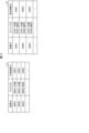
- 11A and 11B are diagrams illustrating examples of model allocation information and logic allocation information.
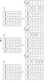
- FIG. 2 is a diagram illustrating an example of time-series data that is the source of training data.
- FIG. 11 is a diagram illustrating an example of pseudo time-series data and teacher data.
- 1 is a flowchart illustrating an example of a model determination method/logic determination method according to an embodiment of the present invention.
- FIG. 2 is a diagram showing an example of the configuration of an information processing system 9 according to an embodiment of the present invention.
- the information processing system 9 is a system having a function of predicting a predetermined event related to the control of equipment 61 included in the facility 6, and determining the control content for the equipment 61 based on the prediction result.
- the information processing system 9 includes an information processing device 1, a prediction device 2a, a prediction device 2b, a control content determination device 3, a storage device 4, a storage device 5, and a facility 6.
- prediction device 2 When there is no need to distinguish between the prediction devices 2a and 2b, they will simply be referred to as "prediction device 2."
- the information processing device 1 identifies equipment among the equipment 61 that is to be controlled as the target equipment, and determines the prediction model 51 to be used for the above-mentioned prediction of the target equipment.
- the information processing device 1 also determines the decision logic for determining the control content for the target equipment.
- the decision logic defines the method for determining the control content, and can also be called the control content decision logic.
- the decision logic may be a computer program for determining the control content.
- the above "control content" also includes at least one of what type of control to perform and what control amount to apply.
- the prediction device 2 performs the above-mentioned prediction for the target equipment using the prediction model 51 determined by the information processing device 1. Since the prediction model 51 is stored in the storage device 5, the prediction device 2 acquires the prediction model 51 determined by the information processing device 1 from the storage device 5 and performs prediction using the acquired prediction model 51.
- FIG. 2 shows two prediction devices 2, prediction devices 2a and 2b.
- Prediction device 2a makes predictions using a prediction model 51a that is commonly used for predictions in multiple pieces of equipment 61.
- prediction device 2b makes predictions using a prediction model 51b that is used for predictions in a specific piece of equipment 61. Note that the number of prediction devices 2 included in the information processing system 9 is arbitrary.
- the control content determination device 3 determines the control content for the target equipment based on the prediction result by the prediction device 2.
- the decision logic determined by the information processing device 1 is used to determine the control content. Since the decision logic for the control content is stored in the storage device 4, the control content determination device 3 acquires the decision logic determined by the information processing device 1 from the storage device 4 and determines the control content using the acquired decision logic. Note that the information processing device 1 may be configured to acquire the decision logic from the storage device 4 and transfer the acquired decision logic to the control content determination device 3.
- the storage device 4 stores common logic 41, individual logic 42, and setting information 43.
- Both common logic 41 and individual logic 42 are logic for determining the control content (or can be rephrased as control content determination logic). Details will be described later, but the common logic 41 is applicable to multiple pieces of equipment 61 in common, and the individual logic 42 is for determining the individual control content for each piece of equipment 61.
- the setting information 43 indicates the settings (for example, the values of constants included in the program or formula that determines the control content) to be applied when performing processing to determine the control content using the common logic 41 and individual logic 42 in each piece of equipment 61.
- a single decision logic is completed by combining the common logic 41 and the individual logic 42 and applying the settings indicated in the setting information 43. Then, the prediction results of the prediction model 51 are input into the completed decision logic, and control content is output.
- Such common logic 41 can be generated by generating a single decision logic for each piece of equipment 61 (a decision logic adapted to each individual piece of equipment 61), and then extracting the parts of the created decision logic that are common to each piece of equipment 61. The remaining parts that are not extracted can then be used as the individual logic 42 for each piece of equipment 61.
- the information processing device 1 determines the common logic 41, individual logic 42, and setting information 43 to be used in the target equipment based on this logic allocation information.
- the storage device 5 stores the prediction model 51.
- a prediction model 51 is assigned to each piece of equipment 61, and the assignment of the prediction model 51 to each piece of equipment 61 is specified by model assignment information. Therefore, the information processing device 1 determines the prediction model 51 to be used for prediction of the target equipment based on this model assignment information.
- FIG. 2 shows two prediction models 51, prediction models 51a and 51b.
- Prediction model 51a is a prediction model 51 that is commonly used for predictions about multiple pieces of equipment 61.
- prediction model 51b is a prediction model 51 that is used for predictions about a specific piece of equipment 61.
- prediction model 51a may be one that can be used for predictions about pieces of equipment 61a and 61b
- prediction model 51b may be one that can be used for predictions about equipment 61c.
- the facility 6 is a facility that includes multiple pieces of equipment 61 that are the subject of control in the information processing system 9.
- FIG. 2 shows three pieces of equipment 61, 61a to 61c, the number of pieces of equipment included in one facility 6 is arbitrary.
- the information processing system 9 can also determine the control content of each piece of equipment 61 included in each facility 6 for multiple facilities 6.
- the equipment 61 may be a single device or apparatus, or may include multiple devices or apparatuses.
- the pieces of equipment 61 included in the facility 6 may operate individually or may work together.
- Example of processing For example, in the information processing system 9, when controlling the equipment 61a, prediction data acquired by the equipment 61a and an equipment ID (IDentification) which is identification information of the equipment 61a are input to the information processing device 1.
- the prediction data is data used for prediction using the prediction model 51. For example, time-series measurement values measured by a sensor or the like installed in the equipment 61a may be used as the prediction data.
- the process of transmitting the prediction data and the equipment ID to the information processing device 1 may be performed by, for example, an information processing device (not shown) installed in the facility 6.
- the user of the information processing system 9 may input these data to the information processing device 1.
- the information processing device 1 determines the prediction model 51 to be used for prediction of the equipment 61a based on the above-mentioned model allocation information, and determines the prediction device 2 to perform the prediction. For example, assume that the prediction model 51 assigned to the equipment 61a is prediction model 51a. In this case, the information processing device 1 determines to use the prediction model 51a for prediction of the equipment 61a, and determines to have the prediction device 2a, which is capable of making predictions using the prediction model 51a, perform the prediction.
- the information processing device 1 performs a predetermined pre-processing on the prediction data of the equipment 61a to generate input data to be input to the prediction model 51a, and transmits the generated input data to the prediction device 2a.
- the prediction device 2a obtains the prediction model 51a from the storage device 5, obtains a prediction result by inputting the input data received from the information processing device 1 into the obtained prediction model 51a, and notifies the information processing device 1 of the prediction result.
- the information processing device 1 determines the common logic 41, individual logic 42, and setting information 43 to be used in determining the control content in the equipment 61a based on the above-mentioned logic allocation information. For example, if the common logic 41, individual logic 42a, and setting information 43a are assigned to the equipment 61a, the information processing device 1 determines that these determination logics and setting information will be used in determining the control content in the equipment 61a.
- the information processing device 1 notifies the control content determination device 3 of the logic ID indicating the common logic 41, the logic ID indicating the individual logic 42a, the setting information ID indicating the setting information 43a, and the prediction result of the prediction device 2a.
- control content determination device 3 obtains the common logic 41, individual logic 42a, and setting information 43a indicated in the notified logic ID and setting information ID from the storage device 4, and uses these to determine the control content according to the prediction result of the prediction device 2a.
- the control content determination device 3 then notifies the equipment 61a (or more precisely, a control device, not shown, that controls the equipment 61a) of the determined control content. This causes the equipment 61a to be controlled. Note that one control device may control one equipment 61, or one control device may control multiple equipment 61.
- the information processing system 9 includes the information processing device 1, the prediction device 2, and the control content determination device 3.
- the information processing device 1 determines the prediction model 51 to be used for predicting the above-mentioned event in the target equipment to be controlled among the plurality of equipments 61 based on model allocation information that assigns the prediction model 51 to be used for predicting the above-mentioned event in the target equipment to be controlled, among the plurality of equipments 61.
- the prediction device 2 predicts the above-mentioned event in the target equipment using the information processing device 1 and the prediction model 51 determined by the information processing device 1.
- the control content determination device 3 determines the control content for the target equipment based on the prediction result by the prediction device 2.
- the information processing system 9 includes a storage device 5 that stores a prediction model 51 assigned to each of the multiple pieces of equipment 61, and the prediction device 2 obtains the prediction model 51 determined by the information processing device 1 from the storage device 5 and performs prediction.
- the prediction models 51 used by each piece of equipment 61 can be managed collectively.
- efficient operation can be achieved by reusing the prediction model 51a among those pieces of equipment 61.
- the prediction device 2 may execute prediction processing using the prediction model 51 in parallel. This makes it possible to shorten the time until prediction results for each target facility are output.
- the information processing system 9 uses a prediction model 51a that is used in common for predictions in multiple facilities 61. For this reason, when a prediction using the prediction model 51a is being performed or is about to be performed for a certain target facility, it may become necessary to perform prediction using the prediction model 51a for other target facilities as well. In such a case, the prediction device 2 executes prediction processing using the prediction model 51a in parallel (in other words, simultaneously in parallel), thereby making it possible to quickly obtain prediction results for each target facility.
- the information processing system 9 includes an information processing device 1 that determines the common logic 41 and individual logic 42 to be used in a target equipment to be controlled among a plurality of equipment 61 based on logic assignment information that assigns, for each of a plurality of predetermined equipment 61, a common logic 41 that is a decision logic for control content commonly applicable to the plurality of equipment 61, and an individual logic 42 for deciding individual control content for each equipment 61, and a control content decision device 3 that determines the control content for the target equipment using the common logic 41 and individual logic 42 decided by the information processing device 1.
- the information processing system 9 it is possible to decide the control content according to the target equipment by combining the common logic 41 and the individual logic 42.
- the common logic 41 and the individual logic 42 can be managed according to their characteristics, it is also possible to improve the manageability of the decision logic.
- the information processing system 9 includes a storage device 4 that stores common logic 41 that can be commonly applied to the multiple pieces of equipment 61, and individual logic 42 that is applied to each of the multiple pieces of equipment 61.
- the control content determination device 3 acquires the common logic 41 and individual logic 42 determined by the information processing device 1 from the storage device 4. This configuration realizes efficient operation in which the common logic 41 stored in the storage device 4 is reused among the multiple pieces of equipment 61.
- the information processing system 9 is applicable to the control of various facilities and equipment.
- the facility 6 may be a plant equipped with a plurality of devices.
- each device equipped in the plant is equipment 61.
- a "plant” is a facility used industrially, equipped with a plurality of devices, and performing a predetermined process such as the production of a product or the treatment of an object using the devices.
- a waste treatment facility is also included in the category of a plant.
- facility 6 is a waste treatment facility that incinerates waste (e.g., combustible garbage) and generates electricity using the exhaust heat
- equipment 61a-61c are incinerators. Then, in equipment 61a-61c, prediction data related to waste incineration and power generation is collected, and predictions are made using prediction model 51 using that prediction data, and equipment 61a-61c is controlled based on the prediction results. This allows for stable automatic control of the waste treatment facility.
- the subject of prediction by the prediction model 51 may be anything related to the control of the equipment 61, and is not particularly limited.
- the prediction model 51 may be a model that predicts the quality of the combustion state in an incinerator.
- the combustion state in the incinerator changes with fluctuations in the quality and amount of the waste to be incinerated, and the amount of steam also changes accordingly.
- the predictive data may be various types of data related to the combustion state.
- time-series sensing data related to automatic combustion control (ACC) may be used as the predictive data.
- ACC automatic combustion control
- Similar prediction data can also be applied when using a prediction model 51 that predicts a numerical value indicating the state of the equipment 61 after a specified time.
- Examples of numerical values indicating the state of the equipment 61 include the amount of steam, the furnace pressure, and the furnace temperature.
- Such a prediction model 51 can be generated by machine learning the relationship between the various data used for prediction as explanatory variables and the numerical value to be predicted as a target variable.
- the prediction model 51 may also predict the content of control to be performed on the equipment 61. For example, various data acquired when an operator performs appropriate intervention control on the equipment 61 (or a specified time before that) are used as explanatory variables, and a value indicating the content of the intervention control is used as a target variable, and the relationship between these is machine-learned to generate such a prediction model 51. Then, by using such a prediction model 51, it is possible to predict which of the intervention controls that the operator has performed in the past should be performed.
- the prediction model 51 may be a neural network prediction model, or a support vector machine, linear regression, random forest, or other prediction model.
- Fig. 1 is a block diagram showing an example of the main configuration of the information processing device 1.
- the information processing device 1 includes a control unit 10 that controls each unit of the information processing device 1, and a storage unit 11 that stores various data used by the information processing device 1.
- the information processing device 1 also includes a communication unit 12 that allows the information processing device 1 to communicate with other devices, an input unit 13 that accepts input of various data to the information processing device 1, and an output unit 14 that allows the information processing device 1 to output various data.
- the control unit 10 also includes a data acquisition unit 101, a target identification unit 102, a model determination unit 103, an input data generation unit 104, a prediction device determination unit 105, a logic determination unit 106, and a management unit 107.
- the storage unit 11 stores model allocation information 111 and logic allocation information 112.
- the data acquisition unit 101 acquires various data used by the information processing device 1. For example, the data acquisition unit 101 acquires time series data acquired by the equipment 61 as prediction data to be used for prediction using the prediction model 51.
- the time series data may be acquired from a sensor or the like arranged in the equipment 61 via the communication unit 12 or the input unit 13, or may be input by a user of the information processing device 1 via the input unit 13.
- the data acquisition unit 101 may also acquire process data in which a predetermined pre-processing has been performed on the above-mentioned time series data.
- the target identification unit 102 identifies the equipment 61 to be controlled from among a predetermined number of pieces of equipment 61 as the target equipment.
- the method of identifying the target equipment is arbitrary and may be determined in advance. For example, when data required for prediction using the prediction model 51 is acquired by the data acquisition unit 101, the target identification unit 102 may identify the equipment 61 from which the data was acquired as the target equipment.
- the model determination unit 103 determines the prediction model 51 to be used for predicting an event in the target equipment identified by the target identification unit 102 based on the model allocation information 111.
- the model allocation information 111 is information indicating the allocation of the prediction model 51 to be used for predicting a specific event related to the control of each of the multiple pieces of equipment 61.
- the input data generation unit 104 generates input data to be input to the prediction model 51. More specifically, the input data generation unit 104 generates input data that can be input to the prediction model 51 by performing standardization or normalization processing as preprocessing on the time series data acquired by the data acquisition unit 101. Note that when the data acquisition unit 101 acquires preprocessed process data, the input data generation unit 104 is omitted.
- the prediction device determination unit 105 determines the prediction device 2 that will perform prediction for the target facility from among a plurality of prediction devices 2 that are capable of performing prediction using the prediction model 51. By providing the information processing device 1 with the prediction device determination unit 105, it becomes possible to avoid concentrating the processing load on one prediction device 2. The method of determining the prediction device 2 will be described later.
- the logic determination unit 106 determines the common logic 41 and individual logic 42 to be used in determining the control content for the target equipment identified by the target identification unit 102 based on the logic assignment information 112.
- the logic assignment information 112 is information indicating the assignment of the common logic 41 and individual logic 42 for each of the multiple equipment 61. Furthermore, the logic determination unit 106 may determine the setting information 43 to be used in the target equipment in addition to the common logic 41 and individual logic 42 to be used in the target equipment.
- the management unit 107 manages the authority for each data stored in the storage device 4 (e.g. authority to add, delete, and change data, authority to access data, etc.). Specifically, the management unit 107 individually sets a user to be given authority for the common logic 41, a user to be given authority for the individual logic 42, and a user to be given authority for the setting information 43. The management unit 107 then identifies the user of the information processing device 1, and allows processing of each data stored in the storage device 4 within the scope of the authority given to that user.
- authority for each data stored in the storage device 4 e.g. authority to add, delete, and change data, authority to access data, etc.
- the management unit 107 individually sets a user to be given authority for the common logic 41, a user to be given authority for the individual logic 42, and a user to be given authority for the setting information 43.
- the management unit 107 identifies the user of the information processing device 1, and allows processing of each data stored in the storage device 4 within the scope of the authority given to that user
- the information processing device 1 includes a target identification unit 102 and a model determination unit 103.
- the target identification unit 102 identifies the equipment 61 to be controlled from among a predetermined number of pieces of equipment 61 as the target equipment.
- the model determination unit 103 determines the prediction model 51 to be used for predicting a predetermined event related to the control of the equipment 61 for each of the plurality of pieces of equipment 61 based on model allocation information 111 that assigns the prediction model 51 to be used for predicting the above-mentioned event in the target equipment.
- model allocation information 111 that assigns the prediction model 51 to be used for predicting the above-mentioned event in the target equipment.
- a common prediction model 51 may be assigned to multiple pieces of equipment 61. This allows the prediction model 51 used by multiple pieces of equipment 61 to be standardized. This makes it possible to simplify the system configuration related to prediction and reduce costs associated with generating and updating the prediction model 51, compared to when different prediction models 51 are used for each piece of equipment 61.
- the information processing device 1 includes a target identification unit 102 that identifies, as a target facility, a facility 61 to be controlled from among a predetermined number of facilities 61, and a logic determination unit 106 that determines the common logic 41 and individual logic 42 to be used to determine the control content in the target facility based on logic assignment information 112 that assigns, to each of the facilities 61, a common logic 41 that is a determination logic for control content commonly applicable to the facilities 61, and an individual logic 42 for determining individual control content in each facility 61.
- the control content for the target equipment can be determined using the common logic 41 and individual logic 42 that correspond to the target equipment. Furthermore, with the above configuration, the common logic 41 and the individual logic 42 can each be managed according to their characteristics, which makes it possible to improve the manageability of the decision logic. For example, with the above configuration, simply modifying one common logic 41 makes it possible to reflect the modified content in the determination of the control content for multiple pieces of equipment 61. Also, for example, it is possible to give only some people the authority to modify the common logic 41 that affects multiple pieces of equipment 61, and give more people the authority to modify the individual logic 42 that affects only a specific piece of equipment 61.
- the logic assignment information 112 may assign setting information 43 indicating settings to be applied when performing processing to determine control content using the common logic 41 and individual logic 42 in each piece of equipment 61 to each piece of equipment 61.
- the logic determination unit 106 may then determine the setting information 43 to be used in the target equipment, in addition to the common logic 41 and individual logic 42 to be used in the target equipment, based on the logic assignment information 112.
- the setting information 43 indicating the settings to be applied when performing processing to determine the control content using the common logic 41 and the individual logic 42 is separate data from the common logic 41 and the individual logic 42. This makes it possible to improve manageability compared to a case in which the decision logic and the setting information are inseparably integrated. For example, it may be possible to allow even someone who is not familiar with the decision logic of the control content to modify the setting information 43.
- the information processing device 1 also includes a management unit 107 that individually sets the persons to whom authority regarding the common logic 41 is to be granted, the persons to whom authority regarding the individual logic 42 is to be granted, and the persons to whom authority regarding the setting information 43 is to be granted.
- This configuration makes it possible to achieve the above-mentioned improvement in manageability.
- the management unit 107 can grant authority to modify both the common logic 41 and the individual logic 42 only to specific individuals, while granting authority to modify the individual logic 42 to other individuals. This makes it possible to easily modify the individual logic 42 in accordance with the actual conditions of each piece of equipment 61, while reducing the possibility of problems occurring that affect multiple pieces of equipment 61 due to modifications to the common logic 41.
- the model allocation information 111 and the logic assignment information 112 may be, for example, information as shown in Fig. 3.
- Fig. 3 is a diagram showing an example of the model allocation information 111 and the logic assignment information 112.
- the model allocation information 111 shown in FIG. 3 is information in which an equipment ID, which is identification information for the equipment 61, a model ID, which is identification information for the prediction model 51, and a prediction device ID, which is identification information for the prediction device 2, are associated with each other.
- the model determination unit 103 can determine the prediction model 51 to be used for prediction of the target equipment identified by the target identification unit 102.
- the model determination unit 103 determines the prediction model 51 associated with A0002 and having a model ID of B0001 as the prediction model 51 to be used for predicting A0002.
- the prediction device determination unit 105 determines that the prediction device 2 associated with A0002 and having a prediction device ID of C0001 will perform prediction using the prediction model 51 with a model ID of B0001.
- the logic assignment information 112 shown in FIG. 3 is information in which an equipment ID, which is identification information for the equipment 61, a logic ID, which is identification information for the common logic 41 or the individual logic 42, and a setting information ID, which is identification information for the setting information 43, are associated with each other.
- the logic determination unit 106 can determine the common logic 41 and individual logic 42, and the setting information 43, to be used in determining the control content for the target equipment identified by the target identification unit 102.
- the logic determination unit 106 determines that the common logic 41 with a logic ID of D1001 and the individual logic 42 with a logic ID of D2001, which are associated with A0003, will be used to determine the control content for A0003. In addition, in this case, the logic determination unit 106 determines that the setting information 43 with a setting information ID of E0003 will be applied when determining the control content using the common logic 41 with a logic ID of D1001 and the individual logic 42 with a logic ID of D2001.
- the prediction device determination unit 105 can determine the prediction device 2 to perform prediction by referring to the model allocation information 111.
- the model allocation information 111 also serves as prediction device allocation information indicating the allocation of the prediction device 2.
- the prediction device allocation information may be data separate from the model allocation information 111.
- the prediction device determination unit 105 may also determine the prediction device 2 to perform prediction so that the periods during which predictions are made by each prediction device 2 do not overlap or the overlapping periods are minimized. For example, multiple prediction devices 2 capable of making predictions using a prediction model 51a commonly used for multiple pieces of equipment 61 may be provided. In this case, the prediction device determination unit 105 may determine, from among the multiple prediction devices 2, one that is not currently performing prediction as the prediction device 2 to perform prediction.
- the prediction model 51 assigned to multiple facilities 61 may be a model generated by machine learning using training data generated by applying standardization or normalization processing to pseudo-time series data that concatenates time series data related to the event to be predicted.
- the characteristics of the time-series data for each piece of equipment 61 are learned, and a prediction model 51 capable of outputting valid prediction results for each piece of equipment 61 is generated. Therefore, with the above configuration, it is possible to standardize the prediction model 51 used by multiple pieces of equipment 61 while also ensuring the validity of the prediction results.
- Figure 4 is a diagram showing an example of time series data that is the source of the teacher data
- Figure 5 is a diagram showing an example of pseudo-time series data generated from the time series data shown in Figure 4, and teacher data generated from the pseudo-time series data.
- FIG. 4 shows an example of time series data 114a to 114c used to generate teacher data generated from steam volume data 113a to 113c, each of which includes a measured value of steam volume measured by a steam volume sensor that measures the amount of steam generated from a boiler installed in equipment 61.
- steam volume data 113a to 113c indicate the steam volumes measured in equipment 61a to 61c in FIG. 2, respectively.
- the steam volume data 113a-113c includes measured values (PV: Process Variable) for each time.
- the steam volume data 113a-113c shown in FIG. 4 also includes set values corresponding to each measured value.
- the set value indicates the target value (steam volume in this example) at the time associated with the set value. In other words, in the equipment 61a-61c from which the steam volume data 113a-113c was obtained, control is performed so that the steam volume approaches the set value.
- time series data 114a-114c can be generated whose elements are the PV/SV value at each time, i.e., the ratio between the measured value and the set value.
- the PV/SV value is close to 1, the condition of the facility can be said to be normal.
- the difference between PV and SV i.e., the difference between the measured value and the set value, may be applied instead of PV/SV.
- the time series data 114a to 114c also include an element called an abnormality flag.
- the value of the abnormality flag at each time indicates whether the state of the equipment 61a to 61c is normal or not. Specifically, in the example of FIG. 4, if the state is normal, the value of the abnormality flag is set to 0, and if the state is not normal, the value of the abnormality flag is set to 1. The criteria for determining whether the state is normal or not can be determined appropriately.
- the value of the abnormality flag is the correct answer data in machine learning, in other words, the objective variable of the prediction model 51 to be generated.
- the prediction model 51 generated using the time series data 114a to 114c is a model that predicts whether the state of the equipment 61 is normal or not.
- the objective variable of the prediction model 51 is arbitrary and is not limited to whether the state of the equipment 61 is normal or not.
- the difference or ratio between the measured value and the set value is a more versatile index than the measured value measured by the equipment 61. Therefore, by using such a versatile index, the pseudo-time series data can be made more natural. In other words, with the above configuration, it is possible to reduce the variation in data caused by differences in the equipment 61. Furthermore, by linking the data collected for each of the multiple pieces of equipment 61, it is possible to reduce the bias that is applied to the fluctuations in values due to time series. Therefore, with the above configuration, it is possible to generate a prediction model 51 with high prediction accuracy.
- FIG. 5 shows pseudo-time series data 115 generated from the time series data 114a to 114c shown in FIG. 4, and teacher data 116 generated from the pseudo-time series data 115.
- the pseudo-time series data 115 is generated by concatenating the time series data 114a to 114c in this order. However, simply concatenating the time series data 114a to 114c as is will result in duplications and inconsistencies in the "time" values.
- the time values in the time series data 114a to 114c are replaced with consecutive values from 1 to 15. These values indicate the order of each data element contained in the time series data 114a to 114c, and can be called order information.
- order information By providing new order information in place of the original "time” values, it is possible to prevent inconsistencies in the "time” values while maintaining the continuity of the data.
- a highly accurate predictive model can be created by standardizing or normalizing the variables.
- statistics of the target data set are required, but these statistics are specific to the data set. Therefore, with conventional technology, it is not possible to link time series data after standardization or normalization to create a single piece of data, or even if it were possible to link the data, learning using such data would significantly degrade the performance of the inference model.
- multiple time series data are concatenated in advance to create a single pseudo-time series data, making it possible to achieve both standardization or normalization processing and concatenation processing of multiple time series data.
- teacher data 116 is generated by applying standardization processing to pseudo-time series data 115.
- the teacher data 116 is generated by applying standardization processing to each of the three data elements included in the pseudo-time series data 115, namely, the measured value, the set value, and the PV/SV.
- the difference between the value of a data element contained in the pseudo-time series data 115 and the average value is divided by the standard deviation for each data element, to generate the teacher data 116.
- training data may be generated by performing a normalization process instead of a standardization process.
- the maximum and minimum values of the data elements included in the pseudo-time series data 115 are calculated.
- the difference between the value of the data element and the calculated minimum value is divided by the data range, i.e., the difference between the maximum value and the minimum value, and this process is performed for each data element to generate training data.
- a prediction model 51 that absorbs the characteristics of the time series data for each facility 61 can be generated.
- the conditions for the standardization or normalization are also used when making predictions using the generated prediction model 51.
- the prediction model 51 is generated by performing machine learning using the teacher data 116 generated as described above.
- the objective variable of the prediction model 51 may be the value of the abnormality flag.
- the explanatory variables of the prediction model 51 may be at least one of the measured values, the set value, and the PV/SV values. Furthermore, values other than these may be included in the explanatory variables. For example, at least one of the measured values, the set value, and the PV/SV values of the temperature time series may be included in the explanatory variables. Furthermore, at least one of the values obtained by standardizing or normalizing these values may be included in the explanatory variables.
- a prediction model 51 with higher versatility is generated compared to when time series data from a single source is used as teacher data.
- prediction model 51a may be generated using teacher data generated from time series data originating from equipment 61a and 61b. This allows prediction model 51a to be capable of making highly accurate predictions for both equipment 61a and 61b.
- the prediction model 51a generated in this manner can also be used for predictions in facilities 61 other than facilities 61a and 61b, as long as they are the same type of facility.
- the prediction model 51a generated in this manner can also be used for predictions in facilities 61 that do not provide the time series data on which the teacher data 116 is based.
- the time series data to be linked is not limited to data collected in multiple different facilities 61.
- the prediction model 51 can also be generated using teacher data 116 that links time series data collected for multiple devices in one facility 61.
- the data acquisition unit 101 may acquire time series data (e.g., time series steam volume data, time series temperature data, or time series pressure data, etc.) relating to the event to be predicted in the target facility. Then, the input data generation unit 104 may generate input data that can be input to the prediction model 51 by performing standardization processing or normalization processing on the acquired time series data as preprocessing.
- time series data e.g., time series steam volume data, time series temperature data, or time series pressure data, etc.
- the input data generation unit 104 may generate input data by performing common pre-processing for target equipment to which the assigned prediction model 51 is commonly assigned. This makes it possible to efficiently perform pre-processing when making predictions for target equipment to which the assigned prediction model 51 is commonly assigned.
- the input data generation unit 104 can standardize the preprocessing of the time series data that is the prediction data acquired from the equipment 61a and the preprocessing of the time series data that is the prediction data acquired from the equipment 61b.
- FIG. 6 is a flow chart showing an example of the process (model determination method/logic determination method) executed by the information processing device 1.
- the data acquisition unit 101 acquires prediction data.
- the prediction data acquired in S1 may include, for example, time series data measured in any of the equipment 61 included in the facility 6.
- the data acquisition unit 101 may also acquire identification information (for example, the equipment ID shown in FIG. 3) of the equipment 61 from which the time series data was measured.
- the target identification unit 102 identifies the equipment 61 to be controlled from among a predetermined number of pieces of equipment 61 as the target equipment. For example, if identification information for equipment 61a is acquired in S1, the target identification unit 102 identifies equipment 61a as the target equipment.
- the model determination unit 103 determines the prediction model 51 to be used to predict a specific event in the target equipment identified in S2, based on the model allocation information 111.
- the prediction device determination unit 105 determines the prediction device 2 that will perform prediction for the target equipment from among multiple prediction devices 2 that are capable of performing prediction using the prediction model 51 determined in S3.
- the input data generation unit 104 performs preprocessing on the prediction data acquired in S1 to generate input data that can be input to the prediction model 51 determined in S3. Note that in S1, preprocessed process data may be acquired as prediction data, in which case the processing in S5 is omitted.
- the input data generation unit 104 notifies the prediction device 2 determined in S4 of the prediction model 51 determined in S3, transmits the input data generated in S5, causes prediction to be made using the prediction model 51, and receives the prediction result from the prediction device 2.
- the logic determination unit 106 determines the common logic 41 and individual logic 42 to be used in the target equipment identified in S2 based on the logic assignment information 112. The logic determination unit 106 also determines the setting information 43 to be applied when using these determination logics. Note that the processing of S7 can be performed at any timing after S2, and is not limited to the example shown in the figure.
- the logic decision unit 106 notifies the control content decision device 3 of the decision made in S7 and the prediction result received in S6. This ends the processing in FIG. 6.
- the model determination method according to this embodiment includes a target identification step (S2) and a model determination step (S3).
- the target identification step (S2) a piece of equipment 61 to be controlled is identified as the target equipment from among a predetermined number of pieces of equipment 61.
- the model determination step (S3) a prediction model 51 to be used for predicting an event in the target equipment is determined based on model assignment information 111 that assigns, for each piece of equipment 61, a prediction model 51 to be used for predicting a predetermined event related to the control of that equipment 61.
- model assignment information 111 that assigns, for each piece of equipment 61, a prediction model 51 to be used for predicting a predetermined event related to the control of that equipment 61.
- the logic determination method according to this embodiment includes a target identification step (S2) of identifying equipment 61 to be controlled from among a predetermined number of pieces of equipment 61 as target equipment, and a logic determination step (S7) of determining the common logic 41 and individual logic 42 to be used in the target equipment based on logic assignment information 112 that assigns, to each of the multiple pieces of equipment 61, a common logic 41 that is a determination logic for control content commonly applicable to the multiple pieces of equipment 61, and an individual logic 42 for determining individual control content for each piece of equipment 61.
- This makes it possible to determine the control content according to the target equipment, and also improves the manageability of the determination logic.
- the execution entity of each process described in each of the above-mentioned embodiments is arbitrary and is not limited to the above-mentioned examples. In other words, as long as the execution entity of each process described in each of the above-mentioned embodiments can be executed, the devices constituting the information processing system 9 can be appropriately changed.
- the information processing device 1 and the control content determination device 3 are separate devices, but they may be combined into a single device.
- the storage device 4 and the storage device 5 may be integrated into a single storage device.
- the information processing device 1 may have the functions of the prediction device 2a.
- the information processing device 1 performs predictions using the prediction model 51a itself, and has the prediction device 2b perform predictions using the prediction model 51b.
- the information processing device 1 determines both the prediction model 51 and the common logic 41 and the individual logic 42, but it is also possible to provide an information processing device that determines the prediction model 51 and an information processing device that determines the common logic 41 and the individual logic 42.
- each process (model determination method/logic determination method) described in FIG. 6 does not necessarily have to be executed by a single device, and these processes can be shared and executed by any number of information processing devices (computers).
- the above-mentioned model determination method and logic determination method can be executed by a single information processing device 1, or by multiple information processing devices.
- the functions of the information processing device 1 can be realized by a program for causing a computer to function as the information processing device 1, and a program (model determination program/logic determination program) for causing a computer to function as each control block of the information processing device 1 (particularly each part included in the control unit 10).
- the information processing device 1 includes a computer having at least one control device (e.g., a processor) and at least one storage device (e.g., a memory) as hardware for executing the above program.
- the above program is executed by this control device and storage device, thereby realizing each of the functions described in the above embodiment.
- the above program may be recorded on one or more computer-readable recording media, not on a temporary basis.
- the recording media may or may not be included in the information processing device 1.
- the above program may be supplied to the information processing device 1 via any wired or wireless transmission medium.
- each of the above control blocks can be realized by a logic circuit.
- a logic circuit for example, an integrated circuit in which a logic circuit that functions as each of the above control blocks is formed is also included in the scope of the present invention.
Landscapes
- Engineering & Computer Science (AREA)
- Physics & Mathematics (AREA)
- General Physics & Mathematics (AREA)
- Theoretical Computer Science (AREA)
- Software Systems (AREA)
- Medical Informatics (AREA)
- Data Mining & Analysis (AREA)
- Evolutionary Computation (AREA)
- Computer Vision & Pattern Recognition (AREA)
- Artificial Intelligence (AREA)
- Computing Systems (AREA)
- General Engineering & Computer Science (AREA)
- Mathematical Physics (AREA)
- Automation & Control Theory (AREA)
- Financial Or Insurance-Related Operations Such As Payment And Settlement (AREA)
- Facsimiles In General (AREA)
- Management, Administration, Business Operations System, And Electronic Commerce (AREA)
- Testing And Monitoring For Control Systems (AREA)
Abstract
対象設備に応じた適切な予測モデルを決定する。情報処理装置(1)は、所定の複数の設備のうち制御対象とする設備を対象設備として特定する対象特定部(102)と、複数の前記設備のそれぞれに対し、当該設備の制御に関する予測モデルを割り当てたモデル割当情報(111)に基づき、対象設備についての予測に用いる予測モデル(51)を決定するモデル決定部(103)と、を備える。
Description
本発明は予測モデルによる予測結果に応じた制御を行う情報処理システム等に関する。
予測モデルによる予測結果を利用することにより、各種設備に対する適切な制御内容を決定する技術が従来技術として知られている。例えば、下記の特許文献1には、廃棄物処理プラント設備において、所定時間後の発生蒸気量を予測する学習モデルを用いて発生蒸気量の予測値を算出することが記載されている。そして、発生蒸気量の予測値と目標発生蒸気量の差をゼロにするような操作値を適用して一次燃焼空気ダンパの制御を行うことが記載されている。
上述のような従来技術は、制御対象が1つであることを前提としているが、実際には制御対象が複数存在することもあり得る。例えば、廃棄物処理プラント設備には複数基の焼却炉が設けられていることがある。そして、複数基の焼却炉があった場合、焼却炉ごとにその特性が相違していることがあるため、同じ学習モデルにより各焼却炉についての予測を行うと予測精度が低下するおそれがある。
以上のことから、複数の設備が存在する場合、制御対象とする対象設備に応じた適切な予測モデルを自動的に決定する技術が望まれるが、そのような技術は従来存在しなかった。本発明の一態様は、複数の設備のうち制御対象とする対象設備に応じた適切な予測モデルを決定することが可能な情報処理装置等を実現することを目的とする。
上記の課題を解決するために、本発明の一態様に係る情報処理装置は、所定の複数の設備のうち制御対象とする設備を対象設備として特定する対象特定部と、複数の前記設備のそれぞれに対し、当該設備の制御に関する所定の事象についての予測に用いる予測モデルを割り当てたモデル割当情報に基づき、前記対象設備における前記事象の予測に用いる予測モデルを決定するモデル決定部と、を備える。
上記の課題を解決するために、本発明の一態様に係る情報処理システムは、所定の複数の設備のそれぞれに対し当該設備の制御に関する所定の事象についての予測に用いる予測モデルを割り当てたモデル割当情報に基づき、複数の前記設備のうち制御対象とする対象設備における前記事象の予測に用いる予測モデルを決定する情報処理装置と、前記情報処理装置が決定する前記予測モデルを用いて前記対象設備における前記事象についての予測を行う予測装置と、前記予測装置による予測結果に基づいて前記対象設備に対する制御内容を決定する制御内容決定装置と、を含む。
上記の課題を解決するために、本発明の一態様に係るモデル決定方法は、1または複数の情報処理装置によって実行されるモデル決定方法であって、所定の複数の設備のうち制御対象とする設備を対象設備として特定する対象特定ステップと、複数の前記設備のそれぞれに対し、当該設備の制御に関する所定の事象についての予測に用いる予測モデルを割り当てたモデル割当情報に基づき、前記対象設備における前記事象の予測に用いる予測モデルを決定するモデル決定ステップと、を含む。
本発明の一態様によれば、対象設備に応じた適切な予測モデルを決定することが可能になる。
〔システム構成〕
図2は、本発明の一実施形態に係る情報処理システム9の構成例を示す図である。情報処理システム9は、施設6に含まれる設備61の制御に関する所定の事象について予測を行い、その予測結果に基づいて設備61に対する制御内容を決定する機能を備えたシステムである。
図2は、本発明の一実施形態に係る情報処理システム9の構成例を示す図である。情報処理システム9は、施設6に含まれる設備61の制御に関する所定の事象について予測を行い、その予測結果に基づいて設備61に対する制御内容を決定する機能を備えたシステムである。
図示のように、情報処理システム9には、情報処理装置1、予測装置2a、予測装置2b、制御内容決定装置3、記憶装置4、記憶装置5、および施設6が含まれている。なお、予測装置2aと予測装置2bを区別する必要がないときには単に「予測装置2」と記載する。後述する予測モデル51a、51b、設備61a~61c、個別ロジック42a~42c、および設定情報43a~43cについても同様である。
情報処理装置1は、設備61のうち制御対象とする設備を対象設備として特定すると共に、対象設備における上述の予測に用いる予測モデル51を決定する。また、情報処理装置1は、対象設備において制御内容を決定するための決定ロジックを決定する。なお、決定ロジックとは、制御内容の決定方法を定めたものであり、制御内容決定ロジックと言い換えることもできる。例えば、制御内容を決定するためのコンピュータプログラムを決定ロジックとしてもよい。また、上記「制御内容」には、どのような制御を行うか、および、どのような制御量を適用するか、の少なくとも何れかが含まれる。
予測装置2は、情報処理装置1が決定する予測モデル51を用いて対象設備についての上述の予測を行う。予測モデル51は、記憶装置5に記憶されているため、予測装置2は、情報処理装置1が決定する予測モデル51を記憶装置5から取得し、取得した予測モデル51を用いて予測を行う。
図2には、予測装置2aと2bという2つの予測装置2を示している。予測装置2aは、複数の設備61における予測に共通して用いられる予測モデル51aを用いて予測を行う。一方、予測装置2bは、特定の設備61における予測に用いられる予測モデル51bを用いて予測を行う。なお、情報処理システム9に含める予測装置2の数は任意である。
制御内容決定装置3は、予測装置2による予測結果に基づいて対象設備に対する制御内容を決定する。制御内容の決定には、情報処理装置1によって決定された決定ロジックが用いられる。制御内容の決定ロジックは、記憶装置4に記憶されているため、制御内容決定装置3は、情報処理装置1が決定する決定ロジックを記憶装置4から取得し、取得した決定ロジックを用いて制御内容を決定する。なお、情報処理装置1が決定ロジックを記憶装置4から取得し、取得した決定ロジックを制御内容決定装置3に転送する構成としてもよい。
記憶装置4は、共通ロジック41と、個別ロジック42と、設定情報43とを記憶する。共通ロジック41と個別ロジック42とは何れも制御内容の決定ロジック(制御内容決定ロジックと言い換えることもできる)である。詳細は後述するが、共通ロジック41は複数の設備61に共通して適用可能なものであり、個別ロジック42は各設備61における個別の制御内容を決定するためのものである。そして、設定情報43は各設備61において共通ロジック41と個別ロジック42を用いて制御内容を決定する処理を行うときに適用すべき設定(例えば制御内容を決定するプログラムや数式に含まれる定数の値など)を示す。
共通ロジック41と個別ロジック42とを組み合わせ、設定情報43に示される設定を適用することにより、1つの決定ロジックが完成する。そして、完成した決定ロジックに予測モデル51の予測結果を入力することにより、制御内容が出力される。このような共通ロジック41は、各設備61のそれぞれについて各1つの決定ロジック(個々の設備61に適合させた決定ロジック)を生成した後、作成した決定ロジックのうち各設備61に共通する部分を抽出することにより生成することができる。そして、抽出されずに残った部分を各設備61の個別ロジック42とすることができる。
詳細は後述するが、各設備61に対する、共通ロジック41、個別ロジック42、および設定情報43の割り当てはロジック割当情報により規定されている。このため、情報処理装置1は、このロジック割当情報に基づいて対象設備で使用する共通ロジック41、個別ロジック42、および設定情報43を決定する。
記憶装置5は、予測モデル51を記憶する。詳細は後述するが、各設備61には予測モデル51が割り当てられており、各設備61に対する予測モデル51の割り当ては、モデル割当情報により規定されている。このため、情報処理装置1は、このモデル割当情報に基づいて対象設備についての予測に用いる予測モデル51を決定する。
図2には、予測モデル51aと51bという2つの予測モデル51を示している。予測モデル51aは、複数の設備61についての予測に共通して用いられる予測モデル51である。一方、予測モデル51bは、特定の設備61についての予測に使いられる予測モデル51である。例えば、予測モデル51aは、設備61aと61bについての予測に用いることができるものであってもよく、予測モデル51bは、設備61cについての予測に用いることができるものであってもよい。なお、記憶装置5に何種類の予測モデル51を記憶させておくかは特に限定されない。
施設6は、情報処理システム9における制御の対象となる設備61を複数備える施設である。図2には、設備61a~61cの3つの設備61を示しているが、1つの施設6に含まれる設備の数は任意である。また、情報処理システム9は、複数の施設6を対象として、各施設6に含まれる各設備61の制御内容を決定することもできる。なお、設備61は、単体の機器あるいは装置であってもよいし、複数の機器あるいは装置を含むものであってもよい。また、施設6に含まれる各設備61は、それぞれ個別に動作するものであってもよいし、協働するものであってもよい。
(処理の例)
例えば、情報処理システム9において、設備61aについての制御を行う場合、設備61aで取得された予測用データと、設備61aの識別情報である設備ID(IDentification)が情報処理装置1に入力される。なお、予測用データとは、予測モデル51を用いた予測に用いられるデータである。例えば、設備61aに設置されたセンサ等により測定された時系列の測定値を予測用データとしてもよい。また、予測用データと設備IDを情報処理装置1に送信する処理は、例えば施設6に設けられた情報処理装置(図示せず)等に行わせてもよい。また、情報処理システム9のユーザが情報処理装置1にこれらのデータを入力するようにしてもよい。
例えば、情報処理システム9において、設備61aについての制御を行う場合、設備61aで取得された予測用データと、設備61aの識別情報である設備ID(IDentification)が情報処理装置1に入力される。なお、予測用データとは、予測モデル51を用いた予測に用いられるデータである。例えば、設備61aに設置されたセンサ等により測定された時系列の測定値を予測用データとしてもよい。また、予測用データと設備IDを情報処理装置1に送信する処理は、例えば施設6に設けられた情報処理装置(図示せず)等に行わせてもよい。また、情報処理システム9のユーザが情報処理装置1にこれらのデータを入力するようにしてもよい。
次に、情報処理装置1が、上述のモデル割当情報に基づいて、設備61aについての予測に用いる予測モデル51を決定すると共に、予測を行わせる予測装置2を決定する。例えば、設備61aに割り当てられた予測モデル51が予測モデル51aであったとする。この場合、情報処理装置1は、設備61aについての予測に予測モデル51aを用いることを決定すると共に、予測モデル51aを用いた予測が可能な予測装置2aに予測を行わせることを決定する。
また、情報処理装置1は、設備61aの予測用データに所定の前処理を施して、予測モデル51aに入力する入力データを生成し、生成した入力データを予測装置2aに送信する。予測装置2aは、記憶装置5から予測モデル51aを取得し、取得した予測モデル51aに情報処理装置1から受信した入力データを入力することにより予測結果を得て、その予測結果を情報処理装置1に通知する。
さらに、情報処理装置1は、上述のロジック割当情報に基づいて、設備61aにおける制御内容の決定に用いる共通ロジック41と個別ロジック42と設定情報43を決定する。例えば、共通ロジック41と個別ロジック42aと設定情報43aが設備61aに割り当てられていた場合、情報処理装置1は、これらの決定ロジックおよび設定情報を設備61aにおける制御内容の決定に用いることを決定する。
そして、情報処理装置1は、共通ロジック41を示すロジックIDと、個別ロジック42aを示すロジックIDと、設定情報43aを示す設定情報IDと、予測装置2aの予測結果とを制御内容決定装置3に通知する。
続いて、制御内容決定装置3は、通知されたロジックIDおよび設定情報IDに示される共通ロジック41と個別ロジック42aと設定情報43aを記憶装置4から取得し、これらを用いて予測装置2aの予測結果に応じた制御内容を決定する。そして、制御内容決定装置3は、決定した制御内容を設備61a(より正確には設備61aを制御する図示しない制御装置)に通知する。これにより、設備61aに対する制御が行われる。なお、1つの制御装置が1つの設備61の制御を行うようにしてもよいし、1つの制御装置が複数の設備61の制御を行うようにしてもよい。
(情報処理システムについて)
以上のように、情報処理システム9は、情報処理装置1と予測装置2と制御内容決定装置3とを含む。情報処理装置1は、所定の複数の設備61のそれぞれに対し当該設備61の制御に関する所定の事象についての予測に用いる予測モデル51を割り当てたモデル割当情報に基づき、複数の設備61のうち制御対象とする対象設備における上記事象の予測に用いる予測モデル51を決定する。予測装置2は、情報処理装置1と、情報処理装置1が決定する予測モデル51を用いて対象設備における上記事象についての予測を行う。制御内容決定装置3は、予測装置2による予測結果に基づいて対象設備に対する制御内容を決定する。よって、情報処理システム9によれば、対象設備に応じた適切な予測モデル51を用いて状態予測を行い、その予測結果に基づいて適切な制御内容を決定することが可能になる。
以上のように、情報処理システム9は、情報処理装置1と予測装置2と制御内容決定装置3とを含む。情報処理装置1は、所定の複数の設備61のそれぞれに対し当該設備61の制御に関する所定の事象についての予測に用いる予測モデル51を割り当てたモデル割当情報に基づき、複数の設備61のうち制御対象とする対象設備における上記事象の予測に用いる予測モデル51を決定する。予測装置2は、情報処理装置1と、情報処理装置1が決定する予測モデル51を用いて対象設備における上記事象についての予測を行う。制御内容決定装置3は、予測装置2による予測結果に基づいて対象設備に対する制御内容を決定する。よって、情報処理システム9によれば、対象設備に応じた適切な予測モデル51を用いて状態予測を行い、その予測結果に基づいて適切な制御内容を決定することが可能になる。
また、情報処理システム9は、複数の設備61のそれぞれに割り当てられた予測モデル51を記憶する記憶装置5を含み、予測装置2は、情報処理装置1が決定する予測モデル51を記憶装置5から取得して予測を行う。この構成によれば、各設備61で使用される予測モデル51を一括して管理することができる。また、複数の設備61(例えば設備61aと61b)で共通して使用される予測モデル51aを記憶装置5に記憶させておくことにより、その予測モデル51aをそれらの設備61で使い回す効率のよい運用が実現される。
また、予測装置2は、対象設備が複数存在し、複数の当該対象設備に対して共通の予測モデル51が割り当てられていた場合に、予測モデル51による予測処理を並列で実行してもよい。これにより、各対象設備についての予測結果が出力されるまでの時間を短縮することが可能になる。情報処理システム9では、複数の設備61における予測に共通して用いられる予測モデル51aを用いる。このため、ある対象設備において予測モデル51aを用いた予測を行っているかまたはこれから行うときに、他の対象設備においても予測モデル51aを用いた予測を行う必要が生じることがある。このような場合に、予測装置2が予測モデル51aを用いた予測処理を並列で実行(言い換えれば同時に並行して実行)することにより、各対象設備についての予測結果を速やかに得ることができる。
また、以上のように、情報処理システム9は、所定の複数の設備61のそれぞれに対し、複数の当該設備61に共通して適用可能な制御内容の決定ロジックである共通ロジック41と、各設備61における個別の制御内容を決定するための個別ロジック42とを割り当てたロジック割当情報に基づき、複数の設備61のうち制御対象とする対象設備で使用する共通ロジック41と個別ロジック42とを決定する情報処理装置1と、情報処理装置1が決定する共通ロジック41と個別ロジック42とを用いて対象設備に対する制御内容を決定する制御内容決定装置3と、を含む。よって、情報処理システム9によれば、共通ロジック41と個別ロジック42の組み合わせにより対象設備に応じた制御内容を決定することが可能になる。また、共通ロジック41と個別ロジック42のそれぞれをその特性に応じて管理することができるため、決定ロジックの管理性を向上させることも可能になる。
また、以上のように、情報処理システム9は複数の設備61に共通して適用可能な共通ロジック41と、複数の設備61のそれぞれで適用される個別ロジック42とを記憶する記憶装置4を含む。そして、制御内容決定装置3は、情報処理装置1が決定した共通ロジック41および個別ロジック42を記憶装置4から取得する。この構成によれば、記憶装置4に記憶されている共通ロジック41を複数の設備61で使い回す効率のよい運用が実現される。
(適用例)
情報処理システム9は、様々な施設および設備の制御に適用可能である。例えば、施設6は、複数の機器を備えたプラントであってもよい。この場合、プラントに備えられた各機器が設備61となる。ここで「プラント」とは、産業的に使用される施設であり、複数の機器を備えており、それらの機器により製品の生産あるいは対象物の処理といった所定の処理を行うものである。例えば、廃棄物処理施設もプラントの範疇に含まれる。
情報処理システム9は、様々な施設および設備の制御に適用可能である。例えば、施設6は、複数の機器を備えたプラントであってもよい。この場合、プラントに備えられた各機器が設備61となる。ここで「プラント」とは、産業的に使用される施設であり、複数の機器を備えており、それらの機器により製品の生産あるいは対象物の処理といった所定の処理を行うものである。例えば、廃棄物処理施設もプラントの範疇に含まれる。
以下では、施設6が、廃棄物(例えば可燃ごみ)を焼却し、その排熱を利用して発電を行う廃棄物処理施設であり、設備61a~61cが焼却炉である例を説明する。そして、設備61a~61cにおいて、廃棄物の焼却や発電に関する予測用データを収集し、それらの予測用データを用いて予測モデル51による予測を行い、その予測結果に基づいて設備61a~61cの制御を行う。これにより、廃棄物処理施設の安定的な自動制御が実現される。
また、予測モデル51による予測の対象は、設備61の制御に関するものであればよく、特に限定されない。例えば、予測モデル51は、焼却炉における燃焼状態の良否を予測するモデルであってもよい。設備61において効率的に発電するためには、発電用のタービンを回すための蒸気量を安定させる必要があるが、焼却する廃棄物の質や量などの変動に伴って焼却炉内の燃焼状態が変化し、これに伴って蒸気量も変化する。燃焼状態の良否を予測する予測モデル51を用いることにより、焼却炉である設備61における燃焼状態の良否を予測し、その予測結果に応じて設備61を適切に制御して、廃棄物の焼却と発電とを安定的に行うことが可能になる。
焼却炉における燃焼状態の良否を予測する予測モデル51を用いる場合、予測用データは、燃焼状態に関連する各種のデータとすればよい。例えば、自動燃焼制御(ACC:Automatic Combustion Control)に関わる時系列のセンシングデータを予測用データとしてもよい。このようなデータを説明変数とし、それらのデータが得られた後、所定時間が経過したときの燃焼状態の良否を示す値を目的変数として、これらの関係を機械学習することにより、所定時間後の燃焼状態の良否を予測する予測モデル51を生成することができる。
また、所定時間後の設備61の状態を示す数値を予測する予測モデル51を用いる場合も、同様の予測用データが適用できる。設備61の状態を示す数値としては、例えば蒸気量、炉内圧力、および炉内温度等が挙げられる。このような予測モデル51は、予測に用いる各種データを説明変数とし、予測したい数値を目的変数として、これらの関係を機械学習することにより生成することができる。
また、予測モデル51は、設備61に対して実行すべき制御の内容を予測するものであってもよい。例えば、設備61に対して、オペレータが適切な介入制御を行ったとき(あるいはその所定時間前)に取得された各種データを説明変数とし、その介入制御の内容を示す値を目的変数として、これらの関係を機械学習することによりこのような予測モデル51を生成することができる。そして、このような予測モデル51を用いることにより、オペレータが過去に実行した介入制御のうち、何れの制御を実行すべきかを予測することができる。
なお、機械学習のアルゴリズムは特に限定されない。例えば、予測モデル51は、ニューラルネットワークの予測モデルであってもよいし、サポートベクターマシン、線形回帰、またはランダムフォレスト等の予測モデルであってもよい。
〔装置構成〕
図1に基づいて情報処理装置1の構成を説明する。図1は、情報処理装置1の要部構成の一例を示すブロック図である。図示のように、情報処理装置1は、情報処理装置1の各部を統括して制御する制御部10と、情報処理装置1が使用する各種データを記憶する記憶部11を備えている。また、情報処理装置1は、情報処理装置1が他の装置と通信するための通信部12、情報処理装置1に対する各種データの入力を受け付ける入力部13、および情報処理装置1が各種データを出力するための出力部14を備えている。
図1に基づいて情報処理装置1の構成を説明する。図1は、情報処理装置1の要部構成の一例を示すブロック図である。図示のように、情報処理装置1は、情報処理装置1の各部を統括して制御する制御部10と、情報処理装置1が使用する各種データを記憶する記憶部11を備えている。また、情報処理装置1は、情報処理装置1が他の装置と通信するための通信部12、情報処理装置1に対する各種データの入力を受け付ける入力部13、および情報処理装置1が各種データを出力するための出力部14を備えている。
また、制御部10には、データ取得部101、対象特定部102、モデル決定部103、入力データ生成部104、予測装置決定部105、ロジック決定部106、および管理部107が含まれている。そして、記憶部11には、モデル割当情報111とロジック割当情報112が記憶されている。
データ取得部101は、情報処理装置1が使用する各種データを取得する。例えば、データ取得部101は、予測モデル51を用いた予測に使用する予測用データとして、設備61で取得された時系列データを取得する。時系列データは、設備61に配置されたセンサ等から通信部12または入力部13を介して取得されてもよいし、情報処理装置1のユーザが入力部13を介して入力してもよい。また、データ取得部101は、上記の時系列データに対して所定の前処理が施されたプロセスデータを取得してもよい。
対象特定部102は、所定の複数の設備61のうち制御対象とする設備61を対象設備として特定する。対象設備の特定方法は任意であり、予め定めておけばよい。例えば、対象特定部102は、予測モデル51を用いた予測に必要なデータがデータ取得部101により取得されたときに、そのデータが取得された設備61を対象設備として特定してもよい。
モデル決定部103は、モデル割当情報111に基づいて、対象特定部102が特定する対象設備における事象の予測に用いる予測モデル51を決定する。モデル割当情報111は、複数の設備61のそれぞれについて、当該設備61の制御に関する所定の事象についての予測に用いる予測モデル51の割り当てを示す情報である。
入力データ生成部104は、予測モデル51に入力する入力データを生成する。より詳細には、入力データ生成部104は、データ取得部101が取得する時系列データに対し、前処理として標準化処理または正規化処理を施すことにより、予測モデル51に入力可能な入力データを生成する。なお、データ取得部101が前処理済みのプロセスデータを取得する場合、入力データ生成部104は省略される。
予測装置決定部105は、予測モデル51を用いて予測を行うことが可能な複数の予測装置2の中から、対象設備についての予測を行わせる予測装置2を決定する。情報処理装置1が予測装置決定部105を備えていることにより、1つの予測装置2に処理の負荷が集中することを避けることが可能になる。予測装置2の決定方法については後述する。
ロジック決定部106は、ロジック割当情報112に基づいて、対象特定部102が特定する対象設備における制御内容の決定に用いる共通ロジック41および個別ロジック42を決定する。ロジック割当情報112は、複数の設備61のそれぞれについて、共通ロジック41および個別ロジック42の割り当てを示す情報である。また、ロジック決定部106は、対象設備で使用する共通ロジック41と個別ロジック42に加え、対象設備で使用する設定情報43を決定してもよい。
管理部107は、記憶装置4に記憶されている各データに関する権限(例えば、データを追加、削除、および変更する権限、データにアクセスする権限等)の管理を行う。具体的には、管理部107は、共通ロジック41に関する権限を与えるユーザと、個別ロジック42に関する権限を与えるユーザと、設定情報43に関する権限を与えるユーザと、をそれぞれ個別に設定する。そして、管理部107は、情報処理装置1のユーザを識別して、そのユーザに与えられた権限の範囲内で記憶装置4に記憶されている各データに対する処理を許容する。
以上のように、情報処理装置1は、対象特定部102と、モデル決定部103とを備える。対象特定部102は、所定の複数の設備61のうち制御対象とする設備61を対象設備として特定する。モデル決定部103は、複数の設備61のそれぞれに対し、当該設備61の制御に関する所定の事象についての予測に用いる予測モデル51を割り当てたモデル割当情報111に基づき、対象設備における上記事象の予測に用いる予測モデル51を決定する。よって、対象設備に応じた適切な予測モデル51を決定することができる。
モデル割当情報111では、複数の設備61に対して共通の予測モデル51が割り当てられていてもよい。これにより、複数の設備61で使用する予測モデル51を共通化することができる。これにより、各設備61でそれぞれ異なる予測モデル51を使用する場合と比べて、予測に関するシステム構成を簡素化することや、予測モデル51の生成および更新等にかかるコストを削減すること等も可能になる。
また、以上のように、情報処理装置1は、所定の複数の設備61のうち制御対象とする設備61を対象設備として特定する対象特定部102と、複数の設備61のそれぞれに対し、複数の当該設備61に共通して適用可能な制御内容の決定ロジックである共通ロジック41と、各設備61における個別の制御内容を決定するための個別ロジック42とを割り当てたロジック割当情報112に基づき、対象設備における制御内容の決定に用いる共通ロジック41と個別ロジック42とを決定するロジック決定部106と、を備える。
上記の構成によれば、対象設備における制御内容を、その対象設備に応じた共通ロジック41と個別ロジック42とを用いて決定することができる。また、上記の構成によれば、共通ロジック41と個別ロジック42のそれぞれをその特性に応じて管理することができるため、決定ロジックの管理性を向上させることも可能になる。例えば、上記の構成によれば、1つの共通ロジック41を修正するだけで、その修正内容を複数の設備61における制御内容の決定に反映させることができる。また、例えば、複数の設備61に影響のある共通ロジック41については一部の者にのみ修正等の権限を与え、特定の設備61のみに影響のある個別ロジック42についてはより多数の者に修正等の権限を与えることも可能になる。
また、以上のように、ロジック割当情報112では、複数の設備61のそれぞれに対し、各設備61において共通ロジック41と個別ロジック42を用いて制御内容を決定する処理を行うときに適用すべき設定を示す設定情報43が割り当てられていてもよい。そして、ロジック決定部106は、ロジック割当情報112に基づき、対象設備で使用する共通ロジック41と個別ロジック42に加え、対象設備で使用する設定情報43を決定してもよい。
この構成によれば、共通ロジック41および個別ロジック42を用いて制御内容を決定する処理を行うときに適用すべき設定を示す設定情報43が、共通ロジック41および個別ロジック42とは別のデータとなっている。よって、決定ロジックと設定情報とが一体不可分となっている場合と比べて管理性を向上させることが可能になる。例えば、制御内容の決定ロジックに精通していない者であっても、設定情報43については修正することを許容すること等も可能になる。
また、以上のように、情報処理装置1は、共通ロジック41に関する権限を与える対象者と、個別ロジック42に関する権限を与える対象者と、設定情報43に関する権限を与える対象者と、をそれぞれ個別に設定する管理部107を備える。この構成によれば、上述したような管理性の向上が実現できる。
例えば、管理部107は、共通ロジック41と個別ロジック42の両方についての修正の権限は特定の者のみに与える一方、個別ロジック42の修正の権限は他の者にも与えることも可能である。これにより、共通ロジック41の修正により複数の設備61に影響が及ぶトラブルが発生する可能性を抑えつつ、設備61ごとの実情に応じた個別ロジック42の修正を容易に実施できるようになる。
〔モデル割当情報とロジック割当情報の例〕
モデル割当情報111およびロジック割当情報112は、例えば図3に示すような情報であってもよい。図3は、モデル割当情報111およびロジック割当情報112の例を示す図である。
モデル割当情報111およびロジック割当情報112は、例えば図3に示すような情報であってもよい。図3は、モデル割当情報111およびロジック割当情報112の例を示す図である。
図3に示されるモデル割当情報111は、設備61の識別情報である設備IDと、予測モデル51の識別情報であるモデルIDと、予測装置2の識別情報である予測装置IDとが対応付けられた情報である。モデル決定部103は、このようなモデル割当情報111を用いることにより、対象特定部102が特定する対象設備についての予測に用いる予測モデル51を決定することができる。
例えば、対象特定部102が特定した対象設備の設備IDがA0002であったとする。この場合、モデル決定部103は、A0002に対応付けられた、モデルIDがB0001の予測モデル51を、A0002についての予測に用いる予測モデル51として決定する。また、この場合、予測装置決定部105は、A0002に対応付けられた、予測装置IDがC0001の予測装置2に、モデルIDがB0001の予測モデル51を用いた予測を行わせることを決定する。
また、図3に示されるロジック割当情報112は、設備61の識別情報である設備IDと、共通ロジック41または個別ロジック42の識別情報であるロジックIDと、設定情報43の識別情報である設定情報IDとが対応付けられた情報である。ロジック決定部106は、このようなロジック割当情報112を用いることにより、対象特定部102が特定する対象設備についての制御内容の決定に用いる共通ロジック41および個別ロジック42と、設定情報43とを決定することができる。
例えば、対象特定部102が特定した対象設備の設備IDがA0003であったとする。この場合、ロジック決定部106は、A0003に対応付けられた、ロジックIDがD1001の共通ロジック41と、ロジックIDがD2001の個別ロジック42とを、A0003についての制御内容の決定に用いることを決定する。また、この場合、ロジック決定部106は、設定情報IDがE0003の設定情報43を、ロジックIDがD1001の共通ロジック41と、ロジックIDがD2001の個別ロジック42とを用いて制御内容を決定するときに適用することを決定する。
〔予測装置の決定方法〕
上述のように、モデル割当情報111にて予測装置2の割り当てを規定しておけば、予測装置決定部105は、モデル割当情報111を参照して予測を行わせる予測装置2を決定することができる。この場合、モデル割当情報111は、予測装置2の割り当てを示す予測装置割当情報を兼ねることになる。予測装置割当情報は、モデル割当情報111とは別のデータとしてもよい。
上述のように、モデル割当情報111にて予測装置2の割り当てを規定しておけば、予測装置決定部105は、モデル割当情報111を参照して予測を行わせる予測装置2を決定することができる。この場合、モデル割当情報111は、予測装置2の割り当てを示す予測装置割当情報を兼ねることになる。予測装置割当情報は、モデル割当情報111とは別のデータとしてもよい。
また、予測装置決定部105は、各予測装置2において予測を行う期間が重複しないか、あるいは重複する期間が最小限となるように、予測を行わせる予測装置2を決定してもよい。例えば、複数の設備61について共通して使用される予測モデル51aを用いた予測が可能な予測装置2を複数設けてもよい。この場合、予測装置決定部105は、複数の予測装置2のうち、その時点で予測を行っていないものを、予測を行わせる予測装置2として決定すればよい。
〔複数の設備に対して割り当てられている予測モデルについて〕
複数の設備61に対して割り当てられている予測モデル51は、予測対象の事象に関する時系列データを連結した擬似的時系列データに対して標準化処理または正規化処理を施すことにより生成された教師データを用いた機械学習により生成されたモデルであってもよい。
複数の設備61に対して割り当てられている予測モデル51は、予測対象の事象に関する時系列データを連結した擬似的時系列データに対して標準化処理または正規化処理を施すことにより生成された教師データを用いた機械学習により生成されたモデルであってもよい。
上記のような教師データを用いて機械学習を行うことにより、各設備61に関する時系列データの特徴がそれぞれ学習されるから、各設備61について妥当な予測結果を出力することが可能な予測モデル51が生成される。よって、上記の構成によれば、複数の設備61で使用する予測モデル51を共通化しつつ、予測結果の妥当性も担保することが可能になる。
以下、図4および図5に基づいて上記の教師データについて説明する。図4は、教師データの元になる時系列データの例を示す図であり、図5は、図4に示される時系列データから生成される擬似的時系列データと、当該擬似的時系列データから生成される教師データの例を示す図である。
図4には、設備61に設けられたボイラから発生する蒸気量を測定する蒸気量センサで測定された蒸気量の測定値を含む蒸気量データ113a~113cのそれぞれから、教師データの生成に用いられる時系列データ114a~114cを生成した例を示している。なお、蒸気量データ113a~113cは、それぞれ図2の設備61a~61cで測定された蒸気量を示している。
図4に示すように、蒸気量データ113a~113cには、時刻ごとの測定値(PV: Process Variable)が含まれている。また、図4に示す蒸気量データ113a~113cには、各測定値に対応する設定値も含まれている。設定値(SV:Set Variable)は、当該設定値に対応付けられた時刻において目標とする値(この例では蒸気量)を示す。つまり、蒸気量データ113a~113cが得られた設備61a~61cでは、蒸気量が設定値に近付くように制御が行われている。
このような蒸気量データ113a~113cから、各時刻におけるPV/SVの値すなわち測定値と設定値との比を要素とする時系列データ114a~114cを生成することができる。PV/SVの値が1に近い場合、施設の状態は正常であるといえる。なお、PV/SVの代わりにPVとSVの差すなわち測定値と設定値の差を適用してもよい。
また、時系列データ114a~114cには、異常フラグという要素が含まれている。各時刻における異常フラグの値は、設備61a~61cの状態が正常であるか否かを示している。具体的には、図4の例では、正常な状態である場合には異常フラグの値を0に、正常な状態ではない場合には異常フラグの値を1にしている。正常か否かの判定基準は適宜定めておけばよい。
異常フラグの値は、機械学習における正解データ、言い換えれば生成する予測モデル51の目的変数である。つまり、時系列データ114a~114cを用いて生成される予測モデル51は、設備61の状態が正常であるか否かを予測するモデルとなる。無論、予測モデル51の目的変数は任意であり、設備61の状態が正常であるか否かに限られない。
測定値と設定値との差や比は、設備61で測定された測定値と比べて汎用性が高い指標である。よって、このような汎用性のある指標を用いることにより、擬似的時系列データを自然なものとすることができる。つまり、上記の構成によれば、設備61が異なることを原因として発生するデータのばらつきを減少させることができる。また、複数の設備61のそれぞれについて収集されたデータを連結することが、時系列性による数値の変動に与えるバイアスを減少させることができる。よって、上記の構成によれば、予測精度の高い予測モデル51を生成することが可能になる。
図5には、図4に示した時系列データ114a~114cから生成された擬似的時系列データ115と、擬似的時系列データ115から生成された教師データ116とを示している。
擬似的時系列データ115は、時系列データ114a~114cをこの順序で連結することにより生成されたものである。ただし、時系列データ114a~114cをそのまま連結しただけでは、「時刻」の値について重複や不整合が生じる。
そこで、擬似的時系列データ115を生成する際には時系列データ114a~114cにおける時刻の値を1~15という連続する値に置き換えている。これらの値は、時系列データ114a~114cに含まれる各データ要素の順序を示すものであり、順序情報と呼ぶことができる。元の「時刻」の値の代わりに新たな順序情報を与えることにより、データの連続性を保持しつつ、「時刻」の値に不整合が生じさせないようにすることができる。
なお、一般的に、データの分布が異なる複数の変数を用いて予測モデルを作成する場合には、変数を標準化処理または正規化処理することで高精度な予測モデルを作成することができる。ここで、標準化処理または正規化処理を実施するためには、対象となるデータセットの統計量が必要となるが、その統計量はデータセットに固有のものとなる。そのため、従来技術では、標準化処理または正規化処理後の時系列データを連結して単一のデータとすることは不可能であるか、もしくは仮に連結できたとしてもそのようなデータを用いた学習は推論モデルの性能を著しく低下させてしまう。
これに対し、上記構成によれば、事前に複数の時系列データを連結して単一の疑似的時系列データとするため、標準化処理または正規化処理と複数の時系列データの連結処理を両立させることができる。
図5の例では、擬似的時系列データ115に対して標準化処理を施すことにより教師データ116を生成している。具体的には、擬似的時系列データ115に含まれる、測定値、設定値、およびPV/SVという3つのデータ要素のそれぞれについて標準化処理を行ったものを教師データ116としている。
具体的には、擬似的時系列データ115に含まれるデータ要素の値と平均値との差を標準偏差で割る、という処理を、各データ要素について行うことにより教師データ116を生成する。例えば、擬似的時系列データ115では、測定値の平均値が9.387であり、標準偏差が0.519である。よって、擬似的時系列データ115における時刻=1の測定値である9.8については、(9.8-9.387)/0.519=0.795との値に標準化している。
また、標準化処理の代わりに正規化処理を施して教師データを生成してもよい。この場合、擬似的時系列データ115に含まれるデータ要素の最大値と最小値をそれぞれ算出する。そして、データ要素の値と算出した上記最小値との差を、データ範囲すなわち上記最大値と上記最小値との差で割る、という処理を、各データ要素について行うことにより教師データを生成する。
以上のように、擬似的時系列データ115に対して標準化処理または正規化処理を施して教師データ116を生成することにより、設備61ごとの時系列データの特性を吸収した予測モデル51を生成することができる。なお、標準化処理または正規化処理の条件(平均、標準偏差、最大値、および最小値などの統計量)は、生成された予測モデル51を用いた予測時にも使用される。
以上のようにして生成された教師データ116を用いて機械学習を行うことにより、予測モデル51が生成される。予測モデル51の目的変数は、異常フラグの値とすればよい。また、予測モデル51の説明変数は、測定値、設定値、およびPV/SVの値の少なくとも何れかとすればよい。また、これら以外の値を説明変数に含めてもよい。例えば、温度の時系列の測定値、設定値、およびPV/SVの値の少なくとも何れかを説明変数に含めてもよい。また、これらの値を標準化処理または正規化処理した値の少なくとも何れかを説明変数に含めてもよい。
複数の設備61から収集された時系列データ114a~114cを連結した擬似的時系列データ115に基づいて生成された教師データ116を用いることにより、単一の出所の時系列データを教師データとする場合と比べて汎用性の高い予測モデル51が生成される。例えば、設備61aおよび61bを出所とする各時系列データから生成された教師データを用いて予測モデル51aを生成してもよい。これにより、予測モデル51aを、設備61aおよび61bの何れについても高精度な予測が可能なものとすることができる。
また、このようにして生成された予測モデル51aは、同種の施設であれば設備61a、61b以外の設備61における予測にも利用できる。つまり、このようにして生成された予測モデル51aは、教師データ116の元になる時系列データを提供していない設備61における予測にも利用可能である。なお、連結する時系列データは、それぞれ異なる複数の設備61で収集されたものに限られない。例えば、1つの設備61における複数の機器について収集された時系列データを連結した教師データ116を用いて予測モデル51を生成することもできる。
上述の教師データ116を用いて生成された予測モデル51を用いる場合、データ取得部101は、対象設備における予測対象の事象に関する時系列データ(例えば、時系列の蒸気量データ、時系列の温度データ、あるいは時系列の圧力データ等)を取得してもよい。そして、入力データ生成部104は、取得した時系列データに対し、前処理として標準化処理または正規化処理を施すことにより、予測モデル51に入力可能な入力データを生成してもよい。
また、入力データ生成部104は、割り当てられた予測モデル51が共通する対象設備については、共通の前処理を施して入力データを生成してもよい。これにより、割り当てられた予測モデル51が共通する対象設備についての予測を行う場合の前処理を効率よく行うことが可能になる。
例えば、教師データ116を用いて、図2に示す設備61a、61bについて共通して使用される予測モデル51aを生成したとする。この場合、入力データ生成部104は、設備61aから取得された予測用データである時系列データに対する前処理と、設備61bから取得された予測用データである時系列データに対する前処理とを共通化することができる。
〔情報処理装置1が実行する処理の流れ〕
情報処理装置1が実行する処理の流れを図6に基づいて説明する。図6は、情報処理装置1が実行する処理(モデル決定方法/ロジック決定方法)の一例を示すフローチャートである。
情報処理装置1が実行する処理の流れを図6に基づいて説明する。図6は、情報処理装置1が実行する処理(モデル決定方法/ロジック決定方法)の一例を示すフローチャートである。
S1では、データ取得部101が予測用データを取得する。S1で取得される予測用データには、例えば、施設6に含まれる設備61の何れかで測定された時系列データが含まれていてもよい。この場合、データ取得部101は、その時系列データが測定された設備61の識別情報(例えば図3に示した設備ID)についても取得してもよい。
S2(対象特定ステップ)では、対象特定部102が、所定の複数の設備61のうち制御対象とする設備61を対象設備として特定する。例えば、S1で設備61aの識別情報が取得された場合、対象特定部102は、設備61aを対象設備として特定する。
S3(モデル決定ステップ)では、モデル決定部103が、モデル割当情報111に基づき、S2で特定された対象設備における所定の事象の予測に用いる予測モデル51を決定する。
S4では、予測装置決定部105が、S3で決定された予測モデル51を用いて予測を行うことが可能な複数の予測装置2の中から、対象設備についての予測を行わせる予測装置2を決定する。
S5では、入力データ生成部104が、S1で取得された予測用データに前処理を施して、S3で決定された予測モデル51に入力可能な入力データを生成する。なお、S1では予測用データとして前処理済みのプロセスデータを取得してもよく、この場合、S5の処理は省略される。
S6では、入力データ生成部104は、S4で決定された予測装置2に、S3で決定された予測モデル51を通知すると共に、S5で生成した入力データを送信し、その予測モデル51を用いた予測を行わせ、その予測装置2から予測結果を受信する。
S7(ロジック決定ステップ)では、ロジック決定部106が、ロジック割当情報112に基づいて、S2で特定された対象設備で使用する共通ロジック41と個別ロジック42とを決定する。また、ロジック決定部106は、これらの決定ロジックを用いる際に適用する設定情報43についても決定する。なお、S7の処理はS2の後であれば任意のタイミングで行うことが可能であり、図示の例に限られない。
S8では、ロジック決定部106は、S7の決定内容と、S6で受信した予測結果を制御内容決定装置3に通知する。これにより、図6の処理は終了する。
以上説明した図6の処理には、本実施形態に係るモデル決定方法が含まれている。すなわち、本実施形態に係るモデル決定方法は、対象特定ステップ(S2)と、モデル決定ステップ(S3)とを含む。対象特定ステップ(S2)では、所定の複数の設備61のうち制御対象とする設備61を対象設備として特定する。モデル決定ステップ(S3)では、複数の設備61のそれぞれに対し、当該設備61の制御に関する所定の事象についての予測に用いる予測モデル51を割り当てたモデル割当情報111に基づき、対象設備における事象の予測に用いる予測モデル51を決定する。よって、対象設備に応じた適切な予測モデル51を決定することが可能になる。
また、以上説明した図6の処理には、本実施形態に係るロジック決定方法も含まれている。すなわち、本実施形態に係るロジック決定方法は、所定の複数の設備61のうち制御対象とする設備61を対象設備として特定する対象特定ステップ(S2)と、複数の設備61のそれぞれに対し、複数の当該設備61に共通して適用可能な制御内容の決定ロジックである共通ロジック41と、各設備に61おける個別の制御内容を決定するための個別ロジック42とを割り当てたロジック割当情報112に基づき、対象設備で使用する共通ロジック41と個別ロジック42とを決定するロジック決定ステップ(S7)と、を含む。よって、対象設備に応じた制御内容を決定することが可能になると共に、決定ロジックの管理性を向上させることも可能になる。
〔変形例〕
上述の各実施形態で説明した各処理の実行主体は任意であり、上述の例に限られない。つまり、上述の各実施形態で説明した各処理を実行可能であれば、情報処理システム9を構成する装置は適宜変更することができる。
上述の各実施形態で説明した各処理の実行主体は任意であり、上述の例に限られない。つまり、上述の各実施形態で説明した各処理を実行可能であれば、情報処理システム9を構成する装置は適宜変更することができる。
例えば、図2の情報処理システム9では、情報処理装置1と制御内容決定装置3は別体の装置であるが、これらをまとめて1つの装置としてもよい。同様に、記憶装置4と記憶装置5を統合して1つの記憶装置としてもよい。この他にも、例えば、情報処理装置1に予測装置2aの機能を持たせてもよい。この場合、情報処理装置1は、予測モデル51aを用いた予測については自ら行い、予測モデル51bを用いた予測は予測装置2bに行わせる。また、情報処理装置1は、予測モデル51の決定と共通ロジック41および個別ロジック42の決定の両方を行うが、予測モデル51を決定する情報処理装置と、共通ロジック41および個別ロジック42を決定する情報処理装置のそれぞれを設けてもよい。
また、図6に記載の各処理(モデル決定方法/ロジック決定方法)の実行主体は、必ずしも1つの装置である必要はなく、それらの処理を複数の任意の情報処理装置(コンピュータ)に分担させて実行することができる。つまり、上述のモデル決定方法およびロジック決定方法は、1つの情報処理装置1に実行させることもできるし、複数の情報処理装置に実行させることもできる。
〔ソフトウェアによる実現例〕
情報処理装置1の機能は、情報処理装置1としてコンピュータを機能させるためのプログラムであって、情報処理装置1の各制御ブロック(特に制御部10に含まれる各部)としてコンピュータを機能させるためのプログラム(モデル決定プログラム/ロジック決定プログラム)により実現することができる。
情報処理装置1の機能は、情報処理装置1としてコンピュータを機能させるためのプログラムであって、情報処理装置1の各制御ブロック(特に制御部10に含まれる各部)としてコンピュータを機能させるためのプログラム(モデル決定プログラム/ロジック決定プログラム)により実現することができる。
この場合、情報処理装置1は、上記プログラムを実行するためのハードウェアとして、少なくとも1つの制御装置(例えばプロセッサ)と少なくとも1つの記憶装置(例えばメモリ)を有するコンピュータを備えている。この制御装置と記憶装置により上記プログラムを実行することにより、上記実施形態で説明した各機能が実現される。
上記プログラムは、一時的ではなく、コンピュータ読み取り可能な、1または複数の記録媒体に記録されていてもよい。この記録媒体は、情報処理装置1が備えていてもよいし、備えていなくてもよい。後者の場合、上記プログラムは、有線または無線の任意の伝送媒体を介して情報処理装置1に供給されてもよい。
また、上記各制御ブロックの機能の一部または全部は、論理回路により実現することも可能である。例えば、上記各制御ブロックとして機能する論理回路が形成された集積回路も本発明の範疇に含まれる。この他にも、例えば量子コンピュータにより上記各制御ブロックの機能を実現することも可能である。
本発明は上述した各実施形態に限定されるものではなく、請求項に示した範囲で種々の変更が可能であり、異なる実施形態にそれぞれ開示された技術的手段を適宜組み合わせて得られる実施形態についても本発明の技術的範囲に含まれる。
1 情報処理装置
102 対象特定部
103 モデル決定部
104 入力データ生成部
105 予測装置決定部
106 ロジック決定部
107 管理部
2 予測装置
3 制御内容決定装置
4、5 記憶装置
61 設備
9 情報処理システム
102 対象特定部
103 モデル決定部
104 入力データ生成部
105 予測装置決定部
106 ロジック決定部
107 管理部
2 予測装置
3 制御内容決定装置
4、5 記憶装置
61 設備
9 情報処理システム
Claims (10)
- 所定の複数の設備のうち制御対象とする設備を対象設備として特定する対象特定部と、
複数の前記設備のそれぞれに対し、当該設備の制御に関する所定の事象についての予測に用いる予測モデルを割り当てたモデル割当情報に基づき、前記対象設備における前記事象の予測に用いる予測モデルを決定するモデル決定部と、を備える情報処理装置。 - 前記モデル割当情報では、複数の前記設備に対して共通の前記予測モデルが割り当てられている、請求項1に記載の情報処理装置。
- 複数の前記設備に対して割り当てられている前記予測モデルは、前記事象に関する時系列データを連結した擬似的時系列データに対して標準化処理または正規化処理を施すことにより生成された教師データを用いた機械学習により生成されたモデルである、請求項2に記載の情報処理装置。
- 前記対象設備における前記事象に関する時系列データを取得するデータ取得部と、
前処理として標準化処理または正規化処理を前記時系列データに施して前記予測モデルに入力可能な入力データを生成する入力データ生成部と、を備え、
前記入力データ生成部は、割り当てられた前記予測モデルが共通する前記対象設備については、共通の前処理を施して前記入力データを生成する、請求項3に記載の情報処理装置。 - 前記予測モデルを用いて予測を行うことが可能な複数の予測装置の中から、前記対象設備についての予測を行わせる予測装置を決定する予測装置決定部を備える、請求項1から4の何れか1項に記載の情報処理装置。
- 所定の複数の設備のそれぞれに対し当該設備の制御に関する所定の事象についての予測に用いる予測モデルを割り当てたモデル割当情報に基づき、複数の前記設備のうち制御対象とする対象設備における前記事象の予測に用いる予測モデルを決定する情報処理装置と、
前記情報処理装置が決定する前記予測モデルを用いて前記対象設備における前記事象についての予測を行う予測装置と、
前記予測装置による予測結果に基づいて前記対象設備に対する制御内容を決定する制御内容決定装置と、を含む情報処理システム。 - 複数の前記設備のそれぞれに割り当てられた前記予測モデルを記憶する記憶装置を含み、
前記予測装置は、前記情報処理装置が決定する前記予測モデルを前記記憶装置から取得して予測を行う、請求項6に記載の情報処理システム。 - 前記予測装置は、前記対象設備が複数存在し、複数の当該対象設備に対して共通の前記予測モデルが割り当てられていた場合に、当該予測モデルによる予測処理を並列で実行する、請求項6または7に記載の情報処理システム。
- 1または複数の情報処理装置によって実行されるモデル決定方法であって、
所定の複数の設備のうち制御対象とする設備を対象設備として特定する対象特定ステップと、
複数の前記設備のそれぞれに対し、当該設備の制御に関する所定の事象についての予測に用いる予測モデルを割り当てたモデル割当情報に基づき、前記対象設備における前記事象の予測に用いる予測モデルを決定するモデル決定ステップと、を含むモデル決定方法。 - 請求項1に記載の情報処理装置としてコンピュータを機能させるためのモデル決定プログラムであって、前記対象特定部および前記モデル決定部としてコンピュータを機能させるためのモデル決定プログラム。
Applications Claiming Priority (2)
| Application Number | Priority Date | Filing Date | Title |
|---|---|---|---|
| JP2023110121A JP2025008176A (ja) | 2023-07-04 | 2023-07-04 | 情報処理装置、情報処理システム、モデル決定方法、およびモデル決定プログラム |
| JP2023-110121 | 2023-07-04 |
Publications (1)
| Publication Number | Publication Date |
|---|---|
| WO2025009404A1 true WO2025009404A1 (ja) | 2025-01-09 |
Family
ID=94171764
Family Applications (1)
| Application Number | Title | Priority Date | Filing Date |
|---|---|---|---|
| PCT/JP2024/022362 Ceased WO2025009404A1 (ja) | 2023-07-04 | 2024-06-20 | 情報処理装置、情報処理システム、モデル決定方法、およびモデル決定プログラム |
Country Status (3)
| Country | Link |
|---|---|
| JP (1) | JP2025008176A (ja) |
| TW (1) | TW202503598A (ja) |
| WO (1) | WO2025009404A1 (ja) |
Citations (6)
| Publication number | Priority date | Publication date | Assignee | Title |
|---|---|---|---|---|
| JP2014026327A (ja) * | 2012-07-24 | 2014-02-06 | Azbil Corp | 実稼働データによる機器の状態診断装置 |
| US20150088606A1 (en) * | 2013-09-20 | 2015-03-26 | Tata Consultancy Services Ltd. | Computer Implemented Tool and Method for Automating the Forecasting Process |
| JP2016091378A (ja) * | 2014-11-06 | 2016-05-23 | 株式会社東芝 | 診断システム、診断方法および診断プログラム |
| JP2016091043A (ja) * | 2014-10-29 | 2016-05-23 | 株式会社日立製作所 | 診断ジョブ生成システム、診断ジョブ生成方法及び診断ジョブ生成表示方法 |
| JP2020027329A (ja) * | 2018-08-09 | 2020-02-20 | パナソニックIpマネジメント株式会社 | 設備診断システム及び設備診断方法 |
| JP2022185159A (ja) * | 2019-11-14 | 2022-12-14 | 株式会社日立産機システム | パターン抽出方法、及び、パターン抽出装置 |
-
2023
- 2023-07-04 JP JP2023110121A patent/JP2025008176A/ja active Pending
-
2024
- 2024-06-20 WO PCT/JP2024/022362 patent/WO2025009404A1/ja not_active Ceased
- 2024-06-27 TW TW113124107A patent/TW202503598A/zh unknown
Patent Citations (6)
| Publication number | Priority date | Publication date | Assignee | Title |
|---|---|---|---|---|
| JP2014026327A (ja) * | 2012-07-24 | 2014-02-06 | Azbil Corp | 実稼働データによる機器の状態診断装置 |
| US20150088606A1 (en) * | 2013-09-20 | 2015-03-26 | Tata Consultancy Services Ltd. | Computer Implemented Tool and Method for Automating the Forecasting Process |
| JP2016091043A (ja) * | 2014-10-29 | 2016-05-23 | 株式会社日立製作所 | 診断ジョブ生成システム、診断ジョブ生成方法及び診断ジョブ生成表示方法 |
| JP2016091378A (ja) * | 2014-11-06 | 2016-05-23 | 株式会社東芝 | 診断システム、診断方法および診断プログラム |
| JP2020027329A (ja) * | 2018-08-09 | 2020-02-20 | パナソニックIpマネジメント株式会社 | 設備診断システム及び設備診断方法 |
| JP2022185159A (ja) * | 2019-11-14 | 2022-12-14 | 株式会社日立産機システム | パターン抽出方法、及び、パターン抽出装置 |
Also Published As
| Publication number | Publication date |
|---|---|
| JP2025008176A (ja) | 2025-01-20 |
| TW202503598A (zh) | 2025-01-16 |
Similar Documents
| Publication | Publication Date | Title |
|---|---|---|
| Gao et al. | Extending the decision field theory to model operators' reliance on automation in supervisory control situations | |
| Mamdikar et al. | Dynamic reliability analysis framework using fault tree and dynamic Bayesian network: A case study of NPP | |
| US4975865A (en) | Method and apparatus for real-time control | |
| KR920003499B1 (ko) | 지식처리를 응용한 계산기 제어 시스템 | |
| JPH03164804A (ja) | プロセス制御システム及び発電プラントプロセス制御システム | |
| Xu et al. | System regression test planning with a fuzzy expert system | |
| CN113282514A (zh) | 问题数据的处理方法、装置、计算机设备和存储介质 | |
| CN121116253B (zh) | 面向多智能体的任务分解与能力路由操作方法及系统 | |
| KR20230015134A (ko) | 플랜트 자동화 제어 장치 및 방법 | |
| Arakelian et al. | Creation of predictive analytics system for power energy objects | |
| CN118466382A (zh) | 一种可完成编写程序仿真的plc控制器 | |
| Kumar | Parametric optimization of repairable systems in IoT: addressing detection delays, imperfect coverage, and fuzzy parameters | |
| WO2025009404A1 (ja) | 情報処理装置、情報処理システム、モデル決定方法、およびモデル決定プログラム | |
| WO2025009405A1 (ja) | 情報処理装置、情報処理システム、ロジック決定方法、およびロジック決定プログラム | |
| Ram et al. | Reliability evaluation of a programmable logic controller based system | |
| KR102766111B1 (ko) | 가변적 라인 공정 플랫폼 설계가 가능한 클라우드 기반 스마트 팩토리 설계 시스템 및 방법 | |
| US12436517B2 (en) | Apparatus for controlling and/or monitoring a technical installation | |
| JP2023154322A (ja) | 情報処理装置、情報処理方法及びプログラム | |
| WO2024009667A1 (ja) | 情報処理装置、推論モデルの生成方法、教師データの生成方法、推論モデル生成プログラム、および教師データ生成プログラム | |
| Batteux et al. | Modeling patterns for the assessment of maintenance policies with AltaRica 3.0 | |
| CN114868090B (zh) | 信息处理装置、信息处理方法及计算机可读取的存储介质 | |
| Kolodenkova et al. | Making Diagnostic Decisions Based on the Assessment of Mixed Production Rules | |
| Choi et al. | Dataflow-based Control Process Identification for ICS Dataset Development | |
| Karpenko et al. | Control of boiler equipments during starting and stopping periods and methods of optimizing these processes through the use of a decision support system with a machine vision subsystem | |
| KR102851699B1 (ko) | 인공지능 기반의 plc 코드 자동 생성 시스템 및 그 방법 |
Legal Events
| Date | Code | Title | Description |
|---|---|---|---|
| 121 | Ep: the epo has been informed by wipo that ep was designated in this application |
Ref document number: 24835917 Country of ref document: EP Kind code of ref document: A1 |
|
| NENP | Non-entry into the national phase |
Ref country code: DE |