WO2025009218A1 - メッシュ復号装置、メッシュ復号方法及びプログラム - Google Patents
メッシュ復号装置、メッシュ復号方法及びプログラム Download PDFInfo
- Publication number
- WO2025009218A1 WO2025009218A1 PCT/JP2024/007923 JP2024007923W WO2025009218A1 WO 2025009218 A1 WO2025009218 A1 WO 2025009218A1 JP 2024007923 W JP2024007923 W JP 2024007923W WO 2025009218 A1 WO2025009218 A1 WO 2025009218A1
- Authority
- WO
- WIPO (PCT)
- Prior art keywords
- mesh
- subdivision
- displacement
- sdu
- unit
- Prior art date
- Legal status (The legal status is an assumption and is not a legal conclusion. Google has not performed a legal analysis and makes no representation as to the accuracy of the status listed.)
- Ceased
Links
Images







Classifications
-
- G—PHYSICS
- G06—COMPUTING OR CALCULATING; COUNTING
- G06T—IMAGE DATA PROCESSING OR GENERATION, IN GENERAL
- G06T9/00—Image coding
-
- H—ELECTRICITY
- H04—ELECTRIC COMMUNICATION TECHNIQUE
- H04N—PICTORIAL COMMUNICATION, e.g. TELEVISION
- H04N19/00—Methods or arrangements for coding, decoding, compressing or decompressing digital video signals
- H04N19/50—Methods or arrangements for coding, decoding, compressing or decompressing digital video signals using predictive coding
- H04N19/597—Methods or arrangements for coding, decoding, compressing or decompressing digital video signals using predictive coding specially adapted for multi-view video sequence encoding
-
- H—ELECTRICITY
- H04—ELECTRIC COMMUNICATION TECHNIQUE
- H04N—PICTORIAL COMMUNICATION, e.g. TELEVISION
- H04N19/00—Methods or arrangements for coding, decoding, compressing or decompressing digital video signals
- H04N19/70—Methods or arrangements for coding, decoding, compressing or decompressing digital video signals characterised by syntax aspects related to video coding, e.g. related to compression standards
Definitions
- the present invention relates to a mesh decoding device, a mesh decoding method, and a program.
- Non-Patent Document 1 the mesh is decoded by dividing it into a basic mesh that represents rough information and a displacement amount that represents detailed information, and the displacement amount is decoded using a video codec.
- Non-Patent Document 1 does not implement a function for decoding parts of a mesh separately or a method for controlling quality for each level of subdivision (LoD), and the same processing is performed on the entire mesh, which means that it is not possible to encode the mesh data according to its local characteristics.
- the present invention has been made in consideration of the above-mentioned problems, and aims to provide a mesh decoding device, mesh decoding method, and program that can efficiently compress the amount of displacement.
- the first feature of the present invention is that it is a mesh decoding device that includes an atlas data decoding unit configured to decode an atlas bitstream and generate and output control information.
- the second feature of the present invention is a mesh decoding method, the mesh decoding method including a step of decoding an atlas bitstream to generate and output first control information.
- the third feature of the present invention is a program for causing a computer to function as a mesh decoding device, the mesh decoding device comprising an atlas data decoding unit configured to decode an atlas bitstream and generate and output first control information.
- the present invention provides a mesh decoding device, mesh decoding method, and program that can efficiently compress the amount of displacement.
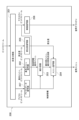
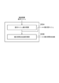
- FIG. 1 is a diagram showing an example of a configuration of a mesh processing system 1 according to an embodiment.
- FIG. 2 is a diagram showing an example of functional blocks of a mesh decoding device 200 according to an embodiment.
- FIG. 3 is a diagram showing an example of the syntax structure of an atlas bitstream.
- FIG. 4A is a diagram showing an example of a syntax configuration of a PDU.
- FIG. 4B is a diagram showing an example of a syntax configuration of an SDU.
- FIG. 4C is a diagram illustrating an example of the syntax configuration of vdmc_lifting_transform_parameters.
- FIG. 5A is a diagram showing an example of a basic mesh.
- FIG. 5B is a diagram showing an example of a subdivision mesh.
- FIG. 6 is a diagram showing an example of functional blocks of the subdivision unit 203 of the mesh decoding device 200 according to an embodiment.
- FIG. 7 is a flowchart showing an example of processing by the basic mesh subdivision unit 203A of the subdivision unit 203 of the mesh decoding device 200 according to an embodiment.
- FIG. 8 is a diagram showing an example of functional blocks of the displacement amount decoding unit 205 of the mesh decoding device 200 according to an embodiment.
- FIG. 1 is a diagram showing an example of the configuration of a mesh processing system 1 according to this embodiment.
- the mesh processing system 1 includes a mesh encoding device 100 and a mesh decoding device 200.
- FIG. 2 is a diagram showing an example of functional blocks of a mesh decoding device 200 according to this embodiment.
- the mesh decoding device 200 has a demultiplexing unit 201, a basic mesh decoding unit 202, a subdivision unit 203, a mesh decoding unit 204, a displacement amount decoding unit 205, a video decoding unit 206, and an atlas data decoding unit 207.
- the demultiplexing unit 201 is configured to separate the multiplexed bit stream into an atlas bit stream, a base mesh bit stream, a displacement amount bit stream, and a texture bit stream.
- the atlas data decoding unit 207 is configured to decode the atlas bitstream and output control information (first control information).
- the base mesh decoding unit 202 is configured to decode the base mesh bit stream to generate and output control information (second control information) and a base mesh.
- the subdivision unit 203 is configured to decode the control information output from the atlas data decoding unit 207 and the control information and base mesh output from the base mesh decoding unit 202, and output a subdivision mesh and subdivision vertex normals.
- the subdivision unit 203 is configured to generate and output the added subdivision vertices and their connection information from the basic mesh decoded by the basic mesh decoding unit 202, using the subdivision method indicated by the above-mentioned control information.
- the base mesh the added subdivision vertices, and their connection information are collectively referred to as the "subdivision mesh.”
- the mesh decoding unit 204 is configured to generate a decoded mesh using the control information, displacement amount, subdivision mesh, and subdivision vertex normals output from the atlas data decoding unit 207 as input.
- the mesh decoding unit 204 is configured to generate and output a decoded mesh using the subdivision mesh and subdivision vertex normals generated by the subdivision unit 203 and the displacement amount decoded by the displacement amount decoding unit 205.
- the displacement amount decoding unit 205 is configured to decode the displacement amount bit stream to generate and output the displacement amount.
- the video decoding unit 206 is configured to decode and output the texture using a video codec.
- Atlas data decoding unit 207 The control information decoded by the atlas data decoding unit 207 will be described below with reference to FIGS.
- Figure 3 shows an example of the syntax structure of an atlas bitstream.
- the atlas bitstream may include a submesh data header (SDH), which is a collection of submesh header information.
- SDH submesh data header
- the atlas bitstream may include SDUs (Submesh data units) that represent data for control information related to the submeshes.
- SDUs Submesh data units
- the atlas bitstream may include a patch data header (PDH), which is a collection of patch header information.
- PDH patch data header
- the atlas bitstream may include patch data units (PDUs) that represent data for control information related to the patch.
- PDUs patch data units
- a submesh is a unit of mesh that can be encoded/decoded as a single unit.
- the base mesh and displacement amount are defined independently for each submesh.
- a patch is defined as one area contained in a submesh.
- FIG. 4B is a diagram showing an example of the syntax configuration of an SDU.
- syntax names different from those shown in FIG. 4B may be used.
- the Description column indicates how each syntax is coded. Also, ue(v) indicates an unsigned zeroth-order exponential Golomb code, and u(n) indicates an n-bit flag.
- the SDU includes a control signal sdu_parameters_enable_flag that indicates whether sdu_subdivision_enable_flag, sdu_displacement_coordinate_system_enable_flag, sdu_transform_method_enable_flag, sdu_transform_parameters__enable_flag, and sdu_attribute_parameter_overwrite_flag are defined for each submesh.
- sdu_parameters_enable_flag indicates whether sdu_subdivision_enable_flag, sdu_displacement_coordinate_system_enable_flag, sdu_transform_method_enable_flag, sdu_transform_parameters__enable_flag, and sdu_attribute_parameter_overwrite_flag are defined for each submesh.
- sdu_subdivision_enable_flag is a control signal that indicates whether or not to perform subdivision for each submesh.
- sdu_displacement_coordinate_system_enable_flag is a control signal indicating whether or not to set a coordinate system that defines the amount of displacement for each submesh. For example, when the value of sdu_displacement_coordinate_system_enable_flag is "1", a coordinate system for the amount of displacement may be defined for each submesh, and when the value of sdu_displacement_coordinate_system_enable_flag is "0", a default coordinate system may be used to define the amount of displacement.
- the default coordinate system may be a known coordinate system such as a Cartesian coordinate system.
- sdu_transform_method_enable_flag is a control signal that indicates whether to set a displacement encoding method for each submesh. For example, when the value of sdu_transform_method_enable_flag is "1", a displacement encoding method may be defined for each submesh, or when the value of sdu_transform_method_enable_flag is "0", a default displacement encoding method may be used.
- the default displacement encoding method may be a known displacement encoding method such as linear wavelet transform.
- sdu_transform_parameters__enable_flag is a control signal indicating whether to define the displacement amount coding parameters for each submesh. For example, when the value of sdu_transform_parameters__enable_flag is "1", a control signal related to the displacement amount coding parameters may be defined for each submesh, or when the value of sdu_transform_parameters__enable_flag is "0", the default displacement amount coding parameters may be used.
- the SDU includes a control signal sdu__attribute_parameter_overwrite__flag that indicates whether sdu_attribute_transform_method_enable_flag, sdu_attribute_transform_parameters_enable_flag, and sdu_attribute_transform_method are defined for each submesh.
- the SDU includes sdu_subdivision_method, which is a control signal that indicates the subdivision method for each submesh. For example, when the value of sdu_subdivision_method is "1", it may be defined to divide each submesh using the mid-edge division method, or when the value of sdu_subdivision_method is "0", it may be configured to define another known subdivision method.
- the SDU includes sdu_subdivision_iteration_count, a control signal that indicates the number of subdivisions for each submesh.
- the SDU includes sdu_transform_method, which is a control signal that indicates the displacement encoding method for each submesh. For example, when the value of sdu_transform_method is "1", it may be configured to encode the displacement using a linear wavelet transform for each submesh, or when the value of sdu_transform_method is "0", it may be configured to define another known displacement encoding method.
- the SDU includes sdu_attribute_transform_method_enable_flag, which is a control signal indicating whether to set an encoding method for attribute information for each submesh. For example, when the value of sdu_attribute_transform_method_enable_flag is "1", the SDU may be configured to define the amount of displacement of attribute information for each submesh using a linear wavelet transform, and when the value of sdu_attribute_transform_method_enable_flag is "0", the SDU may be configured to use the default encoding method.
- the SDU includes sdu_attribute_transform_parameters_enable_flag, which is a control signal indicating whether to set a control signal related to the encoding method of the displacement amount in the attribute information for each submesh. For example, when the value of sdu_attribute_transform_parameters_enable_flag is "1", a control signal related to the encoding of the displacement amount in the attribute information may be defined for each submesh, and when the value of sdu_attribute_transform_parameters_enable_flag is "0", a control signal related to the encoding of the default displacement amount may be defined.
- the SDU includes sdu_attribute_transform_method, which is a control signal that indicates the encoding method of the displacement amount in the attribute information for each submesh. For example, when the value of sdu_attribute_transform_method is "1", it may be configured to encode the displacement amount using a linear wavelet transform for each submesh, or when the value of sdu_attribute_transform_method is "0", it may be configured to define another known encoding method.
- the SDU includes vdmc_ext_ld_displacement_flag, which is a control signal indicating whether one-dimensional displacement encoding is performed for each submesh.
- the SDU may be configured to perform one-dimensional displacement encoding when the value of vdmc_ext_ld_displacement_flag is "1".
- the SDU includes vdmc_transform_lifting_quantization_parameters, which is a control signal that represents the quantization value of the displacement amount at the vertices of subdivision level 0 for each submesh.
- the SDU includes a control signal vdmc_transform_log2_lifting_lod_inverse_scale that represents the quantization scale value of the displacement between subdivision levels for each submesh.
- vdmc_transform_lifting_quantization_parameters and vdmc_transform_log2_lifting_lod_inverse_scale may change the number of dimensions of the parameters based on a control signal indicating whether one-dimensional displacement encoding is performed. For example, if the displacement is encoded by one-dimensional displacement encoding, the number of dimensions of the above-mentioned parameters may be set to 1, and if not, the number of dimensions of the above-mentioned parameters may be set to 3.
- the SDU includes a control signal vdmc_transform_lod_quantization that represents the quantization value for each submesh at each subdivision level.
- vdmc_transform_lod_quantization may change the number of dimensions of the parameters based on a control signal indicating whether one-dimensional displacement encoding is to be performed. For example, when encoding the displacement using one-dimensional displacement encoding, the number of dimensions of the parameters of vdmc_transform_lod_quantization may be set to 1, and otherwise, the number of dimensions of vdmc_transform_lod_quantization may be set to 3.
- Figure 4A is a diagram showing an example of the configuration of a PDU, which is a patch-related syntax of an atlas bitstream.
- the PDU includes vdmc_transform_lifting_quantization_parameters, which is a control signal that represents the quantized value of the displacement amount at the vertices of subdivision level 0 for each patch.
- the PDU includes a control signal vdmc_transform_log2_lifting_lod_inverse_scale that represents the quantization scale value of the displacement between subdivision levels for each patch.
- vdmc_transform_lifting_quantization_parameters and vdmc_transform_log2_lifting_lod_inverse_scale may change the number of dimensions of the parameters based on a control signal indicating whether one-dimensional displacement encoding is performed. For example, if the displacement is encoded by one-dimensional displacement encoding, the number of dimensions of the above-mentioned parameters may be set to 1, and if not, the number of dimensions of the above-mentioned parameters may be set to 3.
- the PDU includes a control signal vdmc_transform_lod_quantization that represents the quantization value for each submesh at each subdivision level.
- vdmc_transform_lod_quantization may change the number of dimensions of the parameters based on a control signal indicating whether one-dimensional displacement encoding is to be performed. For example, when encoding the displacement using one-dimensional displacement encoding, the number of dimensions of the parameters of vdmc_transform_lod_quantization may be set to 1, and otherwise, the number of dimensions of vdmc_transform_lod_quantization may be set to 3.
- vdmc_transform_lod_quantization may be configured to be calculated by subtraction or multiplication based on a subdivision level smaller than the current level.
- Base mesh decoding unit 202 As described above, the base mesh decoder 202 is configured to decode the base mesh bitstream to generate and output base meshes.
- the base mesh is composed of multiple vertices in three-dimensional space and edges connecting these multiple vertices.
- the basic mesh is constructed by combining basic faces represented by three vertices.
- the base mesh decoding unit 202 may be configured to decode the base mesh bitstream using, for example, Draco as shown in Non-Patent Document 2.
- the base mesh decoding unit 202 may be configured to use Draco to independently decode the multiple base meshes.
- the subdivision unit 203 is configured to calculate and output a subdivision mesh and subdivision vertex normals based on the base mesh.
- FIG. 6 shows an example of a functional block of the subdivision unit 203.
- the subdivision unit 203 has a base mesh subdivision unit 203A and a subdivision vertex normal calculation unit 203B.
- the basic mesh subdivision unit 203A is configured to subdivide the basic mesh based on the control information and the basic mesh input from the basic mesh decoding unit 202, and output a subdivision mesh.
- the base mesh subdivision unit 203A may be configured to subdivide each base mesh independently.
- FIG. 7 is a flowchart showing an example of the processing of the basic mesh subdivision unit 203A. Below, an example of the processing of the basic mesh subdivision unit 203A will be explained using FIG. 7.
- step S203A-2 the basic mesh subdivision unit 203A determines whether the variable i satisfies the inequality i ⁇ bsmi_num_submeshes_minus1. If the answer is Yes, the process proceeds to step S203A-3, and if the answer is No, the process ends.
- bsmi_num_submeshes_minus1 is the number of submeshes that make up the mesh minus 1.
- step S203A-3 the basic mesh subdivision unit 203A adds 1 to the variable i.
- step S203A-5 the basic mesh subdivision unit 203A selects an unprocessed submesh.
- an unprocessed submesh is a mesh that has not been subjected to subdivision processing.
- step S203A-7 the basic mesh subdivision unit 203A determines whether the variable j and the number of subdivisions sdu_subdivision_iteration_count satisfy j ⁇ sdu_subdivision_iteration_count. If Yes, the process proceeds to step S203A-2, and if No, the process proceeds to step S203A-8.
- step S203A-8 the basic mesh subdivision unit 203A adds 1 to the variable j and proceeds to step S203A-9.
- step S203A-9 the basic mesh subdivision unit 203A determines whether face subdivision has been completed for all faces in the submesh. If Yes, the process proceeds to step S203A-7; if No, the process proceeds to step S203A-10.
- step S203A-10 the basic mesh subdivision unit 203A selects an unsubdivided face and subdivides the face. The process then proceeds to step S203A-9.
- the basic mesh subdivision unit 203A may subdivide the faces using the mid-edge subdivision method, or may subdivide the faces using other known subdivision methods.
- the base mesh subdivision unit 203A may determine the subdivision method for the submesh based on the value of sdu_subdivision_method.
- Figure 5B is an example of subdivision using the mid-edge division method.
- a subdivision mesh is generated by dividing the midpoints of the edges that make up the mesh.
- the subdivision vertex normal calculation unit 203B is configured to output normals (subdivision vertex normals) defined for each subdivision vertex that constitutes the input subdivision mesh.
- subdivision vertex normal calculation unit 203B may be configured to calculate and output the subdivision vertex normals for each of the multiple subdivision meshes independently.
- the subdivision vertex normal calculation unit 203B may be configured not to calculate the subdivision vertex normal for the corresponding submesh.
- the displacement amount decoding unit 205 includes an arithmetic decoding unit 205A, an inverse quantization unit 205B, and an inverse coefficient conversion unit 205C.
- the displacement amount may be defined so that it is calculated independently for each submesh.
- the arithmetic decoding unit 205A is configured to decode the input displacement amount bit stream using an existing arithmetic coding technique and output quantized displacement amount coefficients.
- the arithmetic decoding unit 205A may be configured to decode the displacement amount independently for each submesh.
- the displacement bitstream may also be configured to be decoded using an existing video codec.
- the inverse quantization unit 205B is configured to decode the input quantized displacement coefficients and output the displacement coefficients.
- the inverse quantization unit 205B may skip the inverse quantization process for the two displacement amount components perpendicular to the normal direction, and perform the inverse quantization process only on the displacement amount normal direction component.
- the inverse quantization unit 205B may inverse quantize the displacement based on the displacement quantization value for each LoD set in vdmc_transform_lod_quantization, which is the displacement quantization value defined for each submesh.
- the inverse quantization unit 205B may also inverse quantize the LoD0 displacement amount based on the quantization value set in vdmc_transform_lifting_quantization_parameters.
- the inverse quantization unit 205B may also calculate a quantization value by multiplying the displacement amount defined for each submesh of LoDi by vdmc_transform_log2_lifting_lod_inverse_scale and vdmc_transform_lifting_quantization_parameters, and inverse quantize the displacement amount of LoDi using the calculated quantization value.
- the displacement amount for each LoD may be inversely quantized based on the quantization value of the displacement amount for each LoD set in vdmc_transform_lod_quantization defined for each patch.
- the inverse quantization unit 205B may also inverse quantize the LoD0 displacement amount based on the quantization value set in vdmc_transform_lifting_quantization_parameters.
- a quantization value may be calculated by multiplying vdmc_transform_log2_lifting_lod_inverse_scale and vdmc_transform_lifting_quantization_parameters defined for each patch, and the displacement of LoDi may be inversely quantized using the calculated quantization value.
- the inverse quantization unit 205B may perform inverse quantization using the uniform quantization described in the reference (Jinhua Yu, "Advantages of uniform scalar dead-zone quantization in image coding system," in 2004 International Conference on Communications, Circuits and Systems (IEEE Cat. No. 04EX914). IEEE, 2004, vol. 2, pp. 805-808.), or may perform inverse quantization using other existing inverse quantization methods.
- the inverse coefficient transformation unit 205C is configured to perform inverse coefficient transformation on the displacement amount coefficient output by the inverse quantization unit 205B, and output a decoded displacement amount.
- the coefficient transformation method may be determined based on sdu_transform_method, which is a control signal that indicates the coding method for the displacement amount for each submesh.
- the inverse coefficient conversion unit 205C may skip the inverse coefficient conversion process for the two displacement components perpendicular to the normal direction, and perform inverse coefficient conversion only on the displacement normal direction component.
- the mesh decoding unit 204 is configured to output a decoded mesh based on the input control information, the subdivision mesh, and the amount of displacement.
- the mesh decoding unit 204 adds the amount of displacement to the vertices of the input subdivision mesh to decode the decoded mesh.
- the mesh decoding unit 204 may output multiple decoded meshes for each submesh based on the displacement amount corresponding to the submesh and the subdivision mesh.
- the mesh decoding unit 204 may also be configured to set a coordinate system for the displacement amount based on a control signal representing a coordinate system for the displacement amount defined for each submesh, and calculate and output the decoded mesh by adding the displacement amount to the subdivision vertices in the set coordinate system.
- the texture decoding unit 206 is configured to decode the input texture bitstream and output a decoded texture.
- the texture decoding unit 206 may be configured to independently decode the texture bitstreams corresponding to the sub-meshes using a known video codec to generate multiple decoded textures.
- the texture decoding unit 206 may be configured to be able to independently decode a portion of the decoded texture based on the input control information.
- efficient compression can be achieved by controlling parameters for each submesh.
- the amount of displacement can be efficiently compressed by performing quantization for each LoD on a submesh or patch basis.
- the above-mentioned mesh encoding device 100 and mesh decoding device 200 may be realized as a program that causes a computer to execute each function (each process).
- Reference Signs List 1 ...Mesh processing system 100
- Mesh encoding device 200 ...Mesh decoding device 201...Demultiplexing unit 202
- Basic mesh decoding unit 203 ...Subdivision unit 203A...Basic mesh subdivision unit 203B
- Subdivision vertex normal calculation unit 204 ...Mesh decoding unit 205
- Dislacement amount decoding unit 205A ...Arithmetic decoding unit 205B
- Inverse quantization unit 205C ...Inverse coefficient conversion unit 206
- Video decoding unit 207 ...Atlas data decoding unit
Landscapes
- Engineering & Computer Science (AREA)
- Multimedia (AREA)
- Signal Processing (AREA)
- Physics & Mathematics (AREA)
- General Physics & Mathematics (AREA)
- Theoretical Computer Science (AREA)
- Compression Or Coding Systems Of Tv Signals (AREA)
Abstract
本発明に係るメッシュ復号装置200は、アトラスビットストリームを復号して制御情報を生成して出力するように構成されているアトラスデータ復号部207を備える。本発明によれば、効率良く変位量を圧縮することができる。
Description
本発明は、メッシュ復号装置、メッシュ復号方法及びプログラムに関する。
非特許文献1では、メッシュを大まかな情報を表す基本メッシュと詳細な情報を表す変位量に分けて復号しており、変位量は映像コーデックによって復号している。
Khaled Mammou, Jungsun Kim, Alexis Tourapis, Dimitri Podborski, Krasimir Kolarov, "[V-CG] Apple’s Dynamic Mesh Coding CfP Response," ISO/IEC JTC 1/SC 29/WG 7 m59281, April 2022.
Google Draco、2022年5月26日アクセス[Online]、https://google.github.io/draco
しかしながら、非特許文献1では、メメッシュの一部に対して、別々に復号する機能や細分割レベル(LoD)ごとに品質を制御する方法が実装されておらず、メッシュ全体に対して同一の処理を行うため、メッシュデータの局所的な特徴に応じた符号化を行うことができないという問題点があった。 そこで、本発明は、上述の課題に鑑みてなされたものであり、効率良く変位量を圧縮できるメッシュ復号装置、メッシュ復号方法及びプログラムを提供することを目的とする。
本発明の第1の特徴は、メッシュ復号装置であって、アトラスビットストリームを復号して制御情報を生成して出力するように構成されているアトラスデータ復号部を備えることを要旨とする。
本発明の第2の特徴は、メッシュ復号方法であって、アトラスビットストリームを復号して第1制御情報を生成して出力する工程を有することを要旨とするメッシュ復号方法。
本発明の第3の特徴は、コンピュータを、メッシュ復号装置として機能させるプログラムであって、前記メッシュ復号装置は、アトラスビットストリームを復号して第1制御情報を生成して出力するように構成されているアトラスデータ復号部を備えることを要旨とする。
本発明によれば、効率良く変位量を圧縮できるメッシュ復号装置、メッシュ復号方法及びプログラムを提供することができる。
以下、本発明の実施の形態について、図面を参照しながら説明する。なお、以下の実施形態における構成要素は、適宜、既存の構成要素等との置き換えが可能であり、また、他の既存の構成要素との組み合わせを含む様々なバリエーションが可能である。したがって、以下の実施形態の記載をもって、特許請求の範囲に記載された発明の内容を限定するものではない。
<第1実施形態>
以下、図1~図8を参照して、本実施形態に係るメッシュ処理システム1について説明する。
以下、図1~図8を参照して、本実施形態に係るメッシュ処理システム1について説明する。
図1は、本実施形態に係るメッシュ処理システム1の構成の一例を示す図である。図1に示すように、メッシュ処理システム1は、メッシュ符号化装置100及びメッシュ復号装置200を備えている。
図2は、本実施形態に係るメッシュ復号装置200の機能ブロックの一例を示す図である。
図2に示すように、メッシュ復号装置200は、多重分離部201と、基本メッシュ復号部202と、細分割部203と、メッシュ復号部204と、変位量復号部205と、映像復号部206と、アトラスデータ復号部207とを有する。
多重分離部201は、多重化されたビットストリームを、アトラスビットストリームと基本メッシュビットストリームと変位量ビットストリームとテクスチャビットストリームとに分離するように構成されている。
アトラスデータ復号部207は、アトラスビットストリームを復号して制御情報(第1制御情報)を出力するように構成されている。
基本メッシュ復号部202は、基本メッシュビットストリームを復号して制御情報(第2制御情報)及び基本メッシュを生成して出力するように構成されている。
細分割部203は、アトラスデータ復号部207から出力された制御情報と基本メッシュ復号部202から出力された制御情報と基本メッシュとを復号して細分割メッシュ及び細分割頂点法線を出力するように構成されている。
具滝的には、細分割部203は、上述の制御情報によって示された細分割手法により、基本メッシュ復号部202によって復号された基本メッシュから、追加された細分割頂点及びそれらの接続情報を生成して出力するように構成されている。
ここで、基本メッシュ、追加された細分割頂点、及び、それらの接続情報を、併せて「細分割メッシュ」と呼ぶ。
メッシュ復号部204は、アトラスデータ復号部207から出力された制御情報と変位量と細分割メッシュと細分割頂点法線を入力として復号メッシュを生成するように構成されている。
具体的には、メッシュ復号部204は、細分割部203で生成された細分割メッシュ及び細分割頂点法線及び変位量復号部205で復号された変位量を用いて、復号メッシュを生成して出力するように構成されている。
変位量復号部205は、変位量ビットストリームを復号して変位量を生成して出力するように構成されている。
映像復号部206は、映像コーデックによってテクスチャを復号して出力するように構成されている。
(アトラスデータ復号部207)
以下、図3~図4を参照して、アトラスデータ復号部207で復号される制御情報について説明する。
以下、図3~図4を参照して、アトラスデータ復号部207で復号される制御情報について説明する。
図3は、アトラスビットストリームのシンタックス構成の一例を示す図である。
図3に示すように、第1に、アトラスビットストリームは、サブメッシュのヘッダ情報の集合である、SDH(Submesh data header:サブメッシュヘッダ)を含んでもよい。
第2に、アトラスビットストリームは、サブメッシュに関する制御情報のデータを表すSDU(Submesh data unit:サブメッシュデータユニット)を含んでもよい。
第3に、アトラスビットストリームは、パッチのヘッダ情報の集合であるPDH(Patch data header:パッチデータヘッダ)を含んでもよい。
第4に、アトラスビットストリームは、パッチに関する制御情報のデータを表すPDU(Patch data unit:パッチデータユニット)を含んでもよい。
ここで、サブメッシュは、単一で符号化/復号することが可能なメッシュの単位である。サブメッシュごとに基本メッシュ及び変位量が独立に定義されている。また、パッチは、サブメッシュに含まれる1領域として定義される。
以下、図4Bを参照して、SDUのシンタックス構成の一例について説明する。図4Bは、SDUのシンタックス構成の一例を示す図である。ここで、シンタックスの機能が同様であれば、図4Bに示すシンタックス名と異なるシンタックス名を用いてもよい。
図4Bに示すSDUのシンタックス構成において、Description欄は、各シンタックスが、どのように符号化されているかを意味している。また、ue(v)は、符号無し0次指数ゴロム符号であることを意味し、u(n)は、nビットのフラグであることを意味する。
SDUは、sdu_subdivision_enable_flag、sdu_displacement_coordinate_system_enable_flag、sdu_transform_method_enable_flag、sdu_transform_parameters__enable_flag、sdu_attribute_parameter_overwrite_flagについて、サブメッシュごとに定義するかどうかを表す制御信号sdu_parameters_enable_flagを含む。
sdu_subdivision_enable_flagは、サブメッシュごとに細分割を行うかどうかを表す制御信号である。
sdu_displacement_coordinate_system_enable_flagは、サブメッシュごとに変位量を定義する座標系を設定するかどうかを表す制御信号である。例えば、sdu_displacement_coordinate_system_enable_flagの値が「1」のとき、サブメッシュごとに変位量の座標系を定義するように構成されていてもよいし、sdu_displacement_coordinate_system_enable_flagの値が「0」のとき、デフォルトの座標系で変位量を定義するように構成されていてもよい。デフォルトの座標系は、直交座標系等の既知の座標系を使用してもよい。
sdu_transform_method_enable_flagは、サブメッシュごとに変位量の符号化手法を設定するかどうかを表す制御信号である。例えば、sdu_transform_method_enable_flagの値が「1」のとき、サブメッシュごとに変位量の符号化手法を定義してもよいし、sdu_transform_method_enable_flagの値が「0」のとき、デフォルトの変位量の符号化手法を使用するように構成されていてもよい。デフォルトの変位量の符号化手法は、リニアウェーブレット変換等の既知の変位量の符号化手法を使用してもよい。
sdu_transform_parameters__enable_flagは、サブメッシュごとに変位量の符号化パラメータを定義するかどうかを表す制御信号である。例えば、sdu_transform_parameters__enable_flagの値が「1」のとき、サブメッシュごとに変位量の符号化パラメータに関する制御信号を定義してもよいし、sdu_transform_parameters__enable_flagの値が「0」のとき、変位量のデフォルトの符号化パラメータを使用するように構成されていてもよい。
SDUは、sdu_attribute_transform_method_enable_flag、sdu_attribute_transform_parameters_enable_flag、sdu_attribute_transform_methodについて、サブメッシュごとに定義するかどうかを表す制御信号sdu__attribute_parameter_overwrite__flagを含む。
SDUは、サブメッシュごとに細分割手法を表す制御信号であるsdu_subdivision_methodを含む。例えば、sdu_subdivision_methodの値が「1」のとき、サブメッシュごとにMid-edge分割法で分割するように定義してもよいし、sdu_subdivision_methodの値が「0」のとき、その他の既知の細分割手法を定義するように構成されていてもよい。
SDUは、サブメッシュごとに細分割の回数を表す制御信号であるsdu_subdivision_iteration_countを含む。
SDUは、サブメッシュごとに変位量の符号化手法を表す制御信号であるsdu_transform_methodを含む。例えば、sdu_transform_methodの値が「1」のとき、サブメッシュごとにリニアウェーブレット変換を用いて変位量を符号化するように構成されていてもよいし、sdu_transform_methodの値が「0」のとき、その他の既知の変位量符号化手法を定義するように構成されていてもよい。
SDUは、サブメッシュごとに属性情報における符号化手法を設定するかどうかを表す制御信号であるsdu_attribute_transform_method_enable_flagを含む。例えば、sdu_attribute_transform_method_enable_flagの値が「1」のとき、サブメッシュごとに属性情報の変位量をリニアウェーブレット変換で定義するように構成されていてもよいし、sdu_attribute_transform_method_enable_flagの値が「0」のとき、デフォルトの符号化手法を使用するように構成されていてもよい。
SDUは、サブメッシュごとに属性情報における変位量の符号化手法に関する制御信号を設定するかどうかを表す制御信号であるsdu_attribute_transform_parameters_enable_flagを含む。例えば、sdu_attribute_transform_parameters_enable_flagの値が「1」のとき、サブメッシュごとに属性情報における変位量の符号化に関する制御信号を定義してもよいし、sdu_attribute_transform_parameters_enable_flagの値が「0」のとき、デフォルトの変位量の符号化に関する制御信号を定義するように構成されていてもよい。
SDUは、サブメッシュごとに属性情報における変位量の符号化手法を表す制御信号であるsdu_attribute_transform_methodを含む。例えば、sdu_attribute_transform_methodの値が「1」のとき、サブメッシュごとにリニアウェーブレット変換を用いて変位量を符号化するように構成されていてもよいし、sdu_attribute_transform_methodの値が「0」のとき、その他の既知の符号化手法を定義するように構成されていてもよい。
SDUは、サブメッシュごとに一次元変位量符号化を行うかどうかを表す制御信号であるvdmc_ext_ld_displacement_flagを含む。例えば、vdmc_ext_ld_displacement_flagの値が「1」のとき、一次元変位量符号化を行うように構成されていてもよい。
SDUは、サブメッシュごとに細分割レベル0の頂点における変位量の量子化値を表す制御信号であるvdmc_transform_lifting_quantization_parametersを含む。
SDUは、サブメッシュごとに細分割レベル間の変位量の量子化スケール値を表す制御信号であるvdmc_transform_log2_lifting_lod_inverse_scaleを含む。
このとき、vdmc_transform_lifting_quantization_parameters及びvdmc_transform_log2_lifting_lod_inverse_scaleは、一次元変位量符号化を行うかどうかを表す制御信号に基づき、パラメータの次元数を変更してもよい。例えば、一次元変位量符号化によって変位量を符号化する場合は、上述のパラメータの次元数を1に、そうでない場合は、上述のパラメータの次元数を3にしてもよい。
SDUは、サブメッシュごとに細分割レベルごとの量子化値を表す制御信号であるvdmc_transform_lod_quantizationを含む。
このとき、vdmc_transform_lod_quantizationは、一次元変位量符号化を行うかどうかを表す制御信号に基づきパラメータの次元数を変更してもよい。例えば、一次元変位量符号化によって変位量を符号化するとき、vdmc_transform_lod_quantizationのパラメータの次元数を1に、そうでない場合は、vdmc_transform_lod_quantizationの次元数を3にしてもよい。
図4Aを参照して、アトラスデータ復号部207で復号されるパッチに関する制御情報について説明する。図4Aは、アトラスビットストリームのパッチ関連のシンタックスであるPDUの構成の一例を示す図である。
PDUは、パッチごとに細分割レベル0の頂点における変位量の量子化値を表す制御信号であるvdmc_transform_lifting_quantization_parametersを含む。
PDUは、パッチごとに細分割レベル間の変位量の量子化スケール値を表す制御信号であるvdmc_transform_log2_lifting_lod_inverse_scaleを含む。
このとき、vdmc_transform_lifting_quantization_parameters及びvdmc_transform_log2_lifting_lod_inverse_scaleは、一次元変位量符号化を行うかどうかを表す制御信号に基づき、パラメータの次元数を変更してもよい。例えば、一次元変位量符号化によって変位量を符号化する場合は、上述のパラメータの次元数を1に、そうでない場合は、上述のパラメータの次元数を3にしてもよい。
PDUは、サブメッシュごとに細分割レベルごとの量子化値を表す制御信号vdmc_transform_lod_quantizationを含む。
vdmc_transform_lod_quantizationは、一次元変位量符号化を行うかどうかを表す制御信号に基づきパラメータの次元数を変更してもよい。例えば、一次元変位量符号化によって変位量を符号化するとき、vdmc_transform_lod_quantizationのパラメータの次元数を1に、そうでない場合は、vdmc_transform_lod_quantizationの次元数を3にしてもよい。
vdmc_transform_lod_quantizationは、現在のレベルより小さい細分割レベルに基づき、差分や乗算によって算出されるように構成されていてもよい。
(基本メッシュ復号部202)
上述のように、基本メッシュ復号部202は、基本メッシュビットストリームを復号して、基本メッシュを生成して出力するように構成されている。
上述のように、基本メッシュ復号部202は、基本メッシュビットストリームを復号して、基本メッシュを生成して出力するように構成されている。
ここで、基本メッシュは、3次元空間における複数の頂点と、かかる複数の頂点を接続する辺とで構成される。このとき、基本メッシュは、1つでもよいし、複数でもよい。
なお、図5Aに示すように、基本メッシュは、3つの頂点で表現される基本面を組み合わせて構成される。
基本メッシュ復号部202は、例えば、非特許文献2に示すDracoを用いて、基本メッシュビットストリームを復号するように構成されていてもよい。
基本メッシュが、複数である場合は、基本メッシュ復号部202は、Dracoを用いて、複数の基本メッシュを独立に復号するように構成されていてもよい。
(細分割部203)
図5~図7を参照して、細分割部203における細分割メッシュの復号方法について説明する。
図5~図7を参照して、細分割部203における細分割メッシュの復号方法について説明する。
細分割部203は、基本メッシュに基づき、細分割メッシュ及び細分割頂点法線を計算して出力するように構成されている。
図6は、細分割部203の機能ブロックの一例を示す図である。
図6に示すように、細分割部203は、基本メッシュ細分割部203Aと、細分割頂点法線計算部203Bとを有する。
(基本メッシュ細分割部203A)
基本メッシュ細分割部203Aは、基本メッシュ復号部202から入力された制御情報と基本メッシュとに基づき、基本メッシュを細分割して、細分割メッシュを出力するように構成されている。
基本メッシュ細分割部203Aは、基本メッシュ復号部202から入力された制御情報と基本メッシュとに基づき、基本メッシュを細分割して、細分割メッシュを出力するように構成されている。
基本メッシュが、複数である場合、基本メッシュ細分割部203Aは、それぞれの基本メッシュに対して独立に細分割するように構成されていてもよい。
図7は、基本メッシュ細分割部203Aの処理の一例を示すフローチャートである。以下、図7を用いて、基本メッシュ細分割部203Aの処理の一例について説明する。
図7に示すように、ステップS203A-1において、基本メッシュ細分割部203Aは、変数iに対して、i=0として、ステップS203A-2に進む。
ステップS203A-2において、基本メッシュ細分割部203Aは、変数iが不等式i≦bsmi_num_submeshes_minus1を満たすかどうかについて判定する。Yesのとき、本処理は、ステップS203A-3に進み、Noのとき、本処理は終了する。ここで、bsmi_num_submeshes_minus1は、メッシュを構成するサブメッシュから1を差し引いた数である。
ステップS203A-3において、基本メッシュ細分割部203Aは、変数iに対して1を加算する。
ステップS203A-4において、基本メッシュ細分割部203Aは、細分割を行うかどうかを表す制御信号であるsdu_subdivision_enable_flagがsdu_subdivision_enable_flag=1を満たすかどうかを判定する。Yesのとき、本処理は、ステップS203A-5に進み、Noのとき、本処理は、ステップS203A-2に進む。
ステップS203A-5において、基本メッシュ細分割部203Aは、未処理サブメッシュを選択する。ここで、未処理サブメッシュは、細分割処理を行っていないメッシュである。
ステップS203A-6において、基本メッシュ細分割部203Aは、変数jに対して、j=0としてステップS203A-7に進む。
ステップS203A-7において、基本メッシュ細分割部203Aは、変数j及び細分割回数sdu_subdivision_iteration_countに対して、j<sdu_subdivision_iteration_countを満たすかどうかを判定する。Yesのとき、本処理は、ステップS203A-2に進み、NoのときステップS203A-8に進む。
ステップS203A-8において、基本メッシュ細分割部203Aは、変数jに対して1を加算し、ステップS203A-9に進む。
ステップS203A-9において、基本メッシュ細分割部203Aは、サブメッシュ内の全ての面に対して面の細分割が完了したかを判定する。Yesのとき、本処理は、ステップS203A-7に進み、Noのとき、本処理は、ステップS203A-10に進む。
ステップS203A-10において、基本メッシュ細分割部203Aは、未細分割面を選択し、面を細分割する。その後、本処理は、ステップS203A-9に進む。
このとき、基本メッシュ細分割部203Aは、Mid-edge分割法を用いて細分割してもよいし、その他の既知の細分割方法を用いて面を細分割してもよい。
ここで、基本メッシュ細分割部203Aは、sdu_subdivision_methodの値に基づき、サブメッシュに対する細分割方法を決定してもよい。
図5Bは、Mid-edge分割法による細分割の一例である。Mid-edge分割法では、メッシュ構成する辺の中点を分割することで、細分割メッシュを生成する。
(細分割頂点法線部計算部203B)
細分割頂点法線計算部203Bは、入力された細分割メッシュを構成する細分割頂点に対して、細分割頂点ごとに定義される法線(細分割頂点法線)を出力するように構成されている。
細分割頂点法線計算部203Bは、入力された細分割メッシュを構成する細分割頂点に対して、細分割頂点ごとに定義される法線(細分割頂点法線)を出力するように構成されている。
入力される細分割メッシュは、複数でもよく、かかる場合、細分割頂点法線計算部203Bは、複数の細分割メッシュに対して独立にそれぞれの細分割頂点法線を計算して、出力するように構成されていてもよい。
サブメッシュごとに、細分割を行うかどうかを表す制御信号であるsdu_subdivision_enable_flagの値が「0」のとき、細分割頂点法線計算部203Bは、該当のサブメッシュに対して、細分割頂点法線を計算しないように構成されていてもよい。
(変位量復号部205)
図8に示すように、変位量復号部205は、算術復号部205Aと、逆量子化部205Bと、逆係数変換部205Cとを備えている。
図8に示すように、変位量復号部205は、算術復号部205Aと、逆量子化部205Bと、逆係数変換部205Cとを備えている。
ここで、変位量は、サブメッシュごとに独立に計算するように定義されていてもよい。
(算術復号部205A)
算術復号部205Aは、入力された変位量ビットストリームを既存の算術符号化技術を用いて復号して、量子化変位量係数を出力するように構成されている。
算術復号部205Aは、入力された変位量ビットストリームを既存の算術符号化技術を用いて復号して、量子化変位量係数を出力するように構成されている。
サブメッシュが、複数存在するとき、算術復号部205Aは、変位量をサブメッシュごとに独立に変位量を復号するように構成されていてもよい。
また、変位量ビットストリームは、既存のビデオコーデックを用いて復号されるように構成されていてもよい。
(逆量子化部205B)
逆量子化部205Bは、入力された量子化変位量係数を復号して、変位量係数を出力するように構成されている。
逆量子化部205Bは、入力された量子化変位量係数を復号して、変位量係数を出力するように構成されている。
変位量符号化手法が、一次元変位量符号化であるとき、逆量子化部205Bは、法線方向に直交する二つの変位量成分に対して逆量子化処理をスキップし、変位量法線方向成分のみに対して逆量子化処理を行ってもよい。
サブメッシュに対してLoDごとに変位量の量子化値が設定されるとき、逆量子化部205Bは、サブメッシュごとに定義されている変位量量子化値であるvdmc_transform_lod_quantizationに設定されている各LoDの変位量の量子化値に基づき、変位量を逆量子化してもよい。
また、逆量子化部205Bは、vdmc_transform_lifting_quantization_parametersに設定されている量子化値に基づき、LoD0の変位量を逆量子化してもよい。
また、逆量子化部205Bは、LoDiのサブメッシュごとに定義されている変位量をvdmc_transform_log2_lifting_lod_inverse_scale及びvdmc_transform_lifting_quantization_parametersの乗算によって量子化値を算出して、算出した量子化値によって、LoDiの変位量を逆量子化してもよい。
パッチに対してLoDごとに変位量の量子化値を設定するとき、パッチごとに定義されているvdmc_transform_lod_quantizationに設定されている各LoDの変位量の量子化値に基づき、各LoDの変位量を逆量子化してもよい。
また、逆量子化部205Bは、vdmc_transform_lifting_quantization_parametersに設定されている量子化値に基づき、LoD0の変位量を逆量子化してもよい。
また、パッチごとに定義されているvdmc_transform_log2_lifting_lod_inverse_scale及びvdmc_transform_lifting_quantization_parametersの乗算によって量子化値を算出して、算出した量子化値によって、LoDiの変位量を逆量子化してもよい。
このとき、逆量子化部205Bは、参考文献(Jinhua Yu, “Advantages of uniform scalar dead-zone quantization in image coding system,” in 2004 International Conference on Communications, Circuits and Systems (IEEE Cat. No. 04EX914). IEEE, 2004, vol. 2, pp. 805-808.)の均一量子化を用いて逆量子化を行ってもよいし、その他の既存の逆量子化手法を用いて逆量子化を行ってもよい。
(逆係数変換部205C)
逆係数変換部205Cは、逆量子化部205Bで出力された変位量係数に対して逆係数変換を行い、復号変位量を出力するように構成されている。
逆係数変換部205Cは、逆量子化部205Bで出力された変位量係数に対して逆係数変換を行い、復号変位量を出力するように構成されている。
このとき、係数変換方法は、サブメッシュごとに変位量の符号化手法を表す制御信号であるsdu_transform_methodに基づき決定されてもよい。
逆係数変換部205Cは、逆係数変換を行うとき、法線方向に直交する2つの変位量成分に対して逆係数変換処理をスキップし、変位量法線方向成分のみに対して逆係数変換を行ってもよい。
(メッシュ復号部204)
メッシュ復号部204は、入力された制御情報、細分割メッシュ及び変位量に基づき、復号メッシュを出力するように構成されている。
メッシュ復号部204は、入力された制御情報、細分割メッシュ及び変位量に基づき、復号メッシュを出力するように構成されている。
メッシュ復号部204は、入力された細分割メッシュの頂点に対して変位量を加算して、復号メッシュを復号する。
このとき、メッシュ復号部204は、サブメッシュに対応する変位量と細分割メッシュとに基づき、サブメッシュごとに複数の復号メッシュを出力してもよい。
また、メッシュ復号部204は、サブメッシュごとに定義されている変位量の座標系を表す制御信号に基づき、変位量の座標系を設定して、設定した座標系上で変位量を細分割頂点に加算することで、復号メッシュを計算して出力するように構成されていてもよい。
(テクスチャ復号部206)
テクスチャ復号部206は、入力されたテクスチャビットストリームを復号して復号テクスチャを出力するように構成されている。
テクスチャ復号部206は、入力されたテクスチャビットストリームを復号して復号テクスチャを出力するように構成されている。
テクスチャ復号部206は、サブメッシュに対応するテクスチャビットストリームに対して既知の映像コーデックを用いて独立に復号して複数の復号テクスチャを生成するように構成されていてもよい。
テクスチャ復号部206は、入力された制御情報に基づいて、復号テクスチャの一部を独立に復号できるように構成されていてもよい。
本実施形態によれば、サブメッシュごとにパラメータ制御を行うことで、効率の良い圧縮を行うことができる。
また、本実施形態によれば、サブメッシュ又はパッチ単位でLoDごとの量子化を行うことで、効率よく変位量を圧縮できる。
上述のメッシュ符号化装置100及びメッシュ復号装置200は、コンピュータに各機能(各工程)を実行させるプログラムであって実現されていてもよい。
なお、本実施形態によれば、例えば、動画像通信において総合的なサービス品質の向上を実現できることから、国連が主導する持続可能な開発目標(SDGs)の目標9「レジリエントなインフラを整備し、持続可能な産業化を推進するとともに、イノベーションの拡大を図る」に貢献することが可能となる。
1…メッシュ処理システム
100…メッシュ符号化装置
200…メッシュ復号装置
201…多重分離部
202…基本メッシュ復号部
203…細分割部
203A…基本メッシュ細分割部
203B…細分割頂点法線計算部
204…メッシュ復号部
205…変位量復号部
205A…算術復号部
205B…逆量子化部
205C…逆係数変換部
206…映像復号部
207…アトラスデータ復号部
100…メッシュ符号化装置
200…メッシュ復号装置
201…多重分離部
202…基本メッシュ復号部
203…細分割部
203A…基本メッシュ細分割部
203B…細分割頂点法線計算部
204…メッシュ復号部
205…変位量復号部
205A…算術復号部
205B…逆量子化部
205C…逆係数変換部
206…映像復号部
207…アトラスデータ復号部
Claims (7)
- メッシュ復号装置であって、
アトラスビットストリームを復号して制御情報を生成して出力するように構成されているアトラスデータ復号部を備えることを特徴とするメッシュ復号装置。 - 前記アトラスデータ復号部は、サブメッシュごとに定義されている一次元変位量符号化を行うかどうかを表す制御信号に基づき、復号する細分割レベル間の変位量量子化スケール値を表す制御信号の次元数を変更することを特徴とする請求項1に記載のメッシュ復号装置。
- 前記アトラスデータ復号部は、サブメッシュごとに定義されている一次元変位量符号化を行うかどうかを表す制御信号に基づき、復号する細分割レベルごとの量子化値を表す制御信号の次元数を変更することを特徴とする請求項1に記載のメッシュ復号装置。
- 前記アトラスデータ復号部は、パッチごとに定義されている一次元変位量符号化を行うかどうかを表す制御信号に基づき、復号する細分割レベル間の変位量の量子化スケール値を表す制御信号の次元数を変更することを特徴とする請求項1に記載のメッシュ復号装置。
- 前記アトラスデータ復号部は、パッチごとに定義されている一次元変位量符号化を行うかどうかを表す制御信号に基づき、復号する細分割レベルごとの量子化値を表す制御信号の次元数を変更することを特徴とする請求項1に記載のメッシュ復号装置。
- メッシュ復号方法であって、
アトラスビットストリームを復号して第1制御情報を生成して出力する工程を有することを特徴とするメッシュ復号方法。 - コンピュータを、メッシュ復号装置として機能させるプログラムであって、
前記メッシュ復号装置は、アトラスビットストリームを復号して第1制御情報を生成して出力するように構成されているアトラスデータ復号部を備えることを特徴とするプログラム。
Applications Claiming Priority (2)
| Application Number | Priority Date | Filing Date | Title |
|---|---|---|---|
| JP2023-109928 | 2023-07-04 | ||
| JP2023109928A JP2025008071A (ja) | 2023-07-04 | 2023-07-04 | メッシュ復号装置、メッシュ復号方法及びプログラム |
Publications (1)
| Publication Number | Publication Date |
|---|---|
| WO2025009218A1 true WO2025009218A1 (ja) | 2025-01-09 |
Family
ID=94172249
Family Applications (1)
| Application Number | Title | Priority Date | Filing Date |
|---|---|---|---|
| PCT/JP2024/007923 Ceased WO2025009218A1 (ja) | 2023-07-04 | 2024-03-03 | メッシュ復号装置、メッシュ復号方法及びプログラム |
Country Status (2)
| Country | Link |
|---|---|
| JP (1) | JP2025008071A (ja) |
| WO (1) | WO2025009218A1 (ja) |
Families Citing this family (2)
| Publication number | Priority date | Publication date | Assignee | Title |
|---|---|---|---|---|
| JP2025146182A (ja) * | 2024-03-22 | 2025-10-03 | Kddi株式会社 | メッシュ復号装置、メッシュ復号方法及びプログラム |
| JP2025146181A (ja) * | 2024-03-22 | 2025-10-03 | Kddi株式会社 | メッシュ復号装置、メッシュ復号方法及びプログラム |
Citations (1)
| Publication number | Priority date | Publication date | Assignee | Title |
|---|---|---|---|---|
| US20210227232A1 (en) * | 2020-01-09 | 2021-07-22 | Lg Electronics Inc. | Point cloud data transmission device, point cloud data transmission method, point cloud data reception device, and point cloud data reception method |
-
2023
- 2023-07-04 JP JP2023109928A patent/JP2025008071A/ja active Pending
-
2024
- 2024-03-03 WO PCT/JP2024/007923 patent/WO2025009218A1/ja not_active Ceased
Patent Citations (1)
| Publication number | Priority date | Publication date | Assignee | Title |
|---|---|---|---|---|
| US20210227232A1 (en) * | 2020-01-09 | 2021-07-22 | Lg Electronics Inc. | Point cloud data transmission device, point cloud data transmission method, point cloud data reception device, and point cloud data reception method |
Non-Patent Citations (2)
| Title |
|---|
| CHOI YIHYUN; JEONG JONG-BEOM; LEE SOONBIN; RYU EUN-SEOK: "Overview of the Video-based Dynamic Mesh Coding (V-DMC) Standard Work", 2022 13TH INTERNATIONAL CONFERENCE ON INFORMATION AND COMMUNICATION TECHNOLOGY CONVERGENCE (ICTC), IEEE, 19 October 2022 (2022-10-19), pages 578 - 581, XP034233613, DOI: 10.1109/ICTC55196.2022.9952734 * |
| MAMMOU KHALED; KIM JUNGSUN; TOURAPIS ALEXIS M.; PODBORSKI DIMITRI; FLYNN DAVID: "Video and Subdivision based Mesh Coding", 2022 10TH EUROPEAN WORKSHOP ON VISUAL INFORMATION PROCESSING (EUVIP), IEEE, 11 September 2022 (2022-09-11), pages 1 - 6, XP034212156, DOI: 10.1109/EUVIP53989.2022.9922888 * |
Also Published As
| Publication number | Publication date |
|---|---|
| JP2025008071A (ja) | 2025-01-20 |
Similar Documents
| Publication | Publication Date | Title |
|---|---|---|
| WO2025009218A1 (ja) | メッシュ復号装置、メッシュ復号方法及びプログラム | |
| US20260122272A1 (en) | Mesh decoding device, mesh decoding method, and program | |
| JP7751560B2 (ja) | メッシュ復号装置、メッシュ復号方法及びプログラム | |
| KR960040018A (ko) | 휴먼 비쥬얼 시스템 모델링을 이용한 웨이블렛 영상 압축/복원 장치 및 방법 | |
| WO2022070469A1 (ja) | 点群復号装置、点群復号方法及びプログラム | |
| JP7651762B2 (ja) | 点群復号装置、点群復号方法及びプログラム | |
| WO2022071285A1 (ja) | 点群復号装置、点群復号方法及びプログラム | |
| WO2022071284A1 (ja) | 点群復号装置、点群復号方法及びプログラム | |
| US20260038158A1 (en) | Mesh decoding device, mesh decoding method, and program | |
| WO2025150312A1 (ja) | メッシュ復号装置、メッシュ復号方法及びプログラム | |
| JP7767263B2 (ja) | メッシュ復号装置、メッシュ復号方法及びプログラム | |
| JP3471366B2 (ja) | 画像圧縮・伸張方法および画像圧縮・伸張装置 | |
| Kaur et al. | Image Compression Techniques with LZW method | |
| JP2024152414A (ja) | メッシュ復号装置、メッシュ復号方法及びプログラム | |
| JP2024152416A (ja) | メッシュ復号装置、メッシュ復号方法及びプログラム | |
| WO2025150311A1 (ja) | メッシュ復号装置、メッシュ復号方法及びプログラム | |
| US20260032277A1 (en) | Mesh decoding device, mesh decoding method, and program | |
| WO2026009479A1 (ja) | メッシュ復号装置、メッシュ復号方法及びプログラム | |
| WO2026009478A1 (ja) | メッシュ復号装置、メッシュ復号方法及びプログラム | |
| WO2025074659A1 (ja) | メッシュ復号装置、メッシュ復号方法及びプログラム | |
| JPWO1999007155A1 (ja) | 画像圧縮・伸張方法および画像圧縮・伸張装置 | |
| WO2025074658A1 (ja) | メッシュ復号装置、メッシュ復号方法及びプログラム | |
| KR100303744B1 (ko) | 화상 압축·신장 방법 및 화상 압축·신장 장치 | |
| WO2024143058A1 (ja) | メッシュ復号装置、メッシュ復号方法及びプログラム | |
| WO2025215915A1 (ja) | メッシュ復号装置、メッシュ復号方法及びプログラム |
Legal Events
| Date | Code | Title | Description |
|---|---|---|---|
| 121 | Ep: the epo has been informed by wipo that ep was designated in this application |
Ref document number: 24835741 Country of ref document: EP Kind code of ref document: A1 |
|
| NENP | Non-entry into the national phase |
Ref country code: DE |