WO2025009124A1 - 画像診断支援装置、画像診断支援システム、及び画像診断支援方法 - Google Patents
画像診断支援装置、画像診断支援システム、及び画像診断支援方法 Download PDFInfo
- Publication number
- WO2025009124A1 WO2025009124A1 PCT/JP2023/025015 JP2023025015W WO2025009124A1 WO 2025009124 A1 WO2025009124 A1 WO 2025009124A1 JP 2023025015 W JP2023025015 W JP 2023025015W WO 2025009124 A1 WO2025009124 A1 WO 2025009124A1
- Authority
- WO
- WIPO (PCT)
- Prior art keywords
- image
- diagnostic
- unit
- diagnosis support
- candidate region
- Prior art date
- Legal status (The legal status is an assumption and is not a legal conclusion. Google has not performed a legal analysis and makes no representation as to the accuracy of the status listed.)
- Ceased
Links
Images





Classifications
-
- G—PHYSICS
- G16—INFORMATION AND COMMUNICATION TECHNOLOGY [ICT] SPECIALLY ADAPTED FOR SPECIFIC APPLICATION FIELDS
- G16H—HEALTHCARE INFORMATICS, i.e. INFORMATION AND COMMUNICATION TECHNOLOGY [ICT] SPECIALLY ADAPTED FOR THE HANDLING OR PROCESSING OF MEDICAL OR HEALTHCARE DATA
- G16H50/00—ICT specially adapted for medical diagnosis, medical simulation or medical data mining; ICT specially adapted for detecting, monitoring or modelling epidemics or pandemics
- G16H50/20—ICT specially adapted for medical diagnosis, medical simulation or medical data mining; ICT specially adapted for detecting, monitoring or modelling epidemics or pandemics for computer-aided diagnosis, e.g. based on medical expert systems
-
- A—HUMAN NECESSITIES
- A61—MEDICAL OR VETERINARY SCIENCE; HYGIENE
- A61B—DIAGNOSIS; SURGERY; IDENTIFICATION
- A61B1/00—Instruments for performing medical examinations of the interior of cavities or tubes of the body by visual or photographical inspection, e.g. endoscopes; Illuminating arrangements therefor
- A61B1/04—Instruments for performing medical examinations of the interior of cavities or tubes of the body by visual or photographical inspection, e.g. endoscopes; Illuminating arrangements therefor combined with photographic or television appliances
- A61B1/045—Control thereof
-
- G—PHYSICS
- G06—COMPUTING OR CALCULATING; COUNTING
- G06T—IMAGE DATA PROCESSING OR GENERATION, IN GENERAL
- G06T7/00—Image analysis
- G06T7/0002—Inspection of images, e.g. flaw detection
- G06T7/0012—Biomedical image inspection
-
- G—PHYSICS
- G16—INFORMATION AND COMMUNICATION TECHNOLOGY [ICT] SPECIALLY ADAPTED FOR SPECIFIC APPLICATION FIELDS
- G16H—HEALTHCARE INFORMATICS, i.e. INFORMATION AND COMMUNICATION TECHNOLOGY [ICT] SPECIALLY ADAPTED FOR THE HANDLING OR PROCESSING OF MEDICAL OR HEALTHCARE DATA
- G16H30/00—ICT specially adapted for the handling or processing of medical images
- G16H30/40—ICT specially adapted for the handling or processing of medical images for processing medical images, e.g. editing
-
- G—PHYSICS
- G06—COMPUTING OR CALCULATING; COUNTING
- G06T—IMAGE DATA PROCESSING OR GENERATION, IN GENERAL
- G06T2207/00—Indexing scheme for image analysis or image enhancement
- G06T2207/10—Image acquisition modality
- G06T2207/10024—Color image
-
- G—PHYSICS
- G06—COMPUTING OR CALCULATING; COUNTING
- G06T—IMAGE DATA PROCESSING OR GENERATION, IN GENERAL
- G06T2207/00—Indexing scheme for image analysis or image enhancement
- G06T2207/10—Image acquisition modality
- G06T2207/10068—Endoscopic image
-
- G—PHYSICS
- G06—COMPUTING OR CALCULATING; COUNTING
- G06T—IMAGE DATA PROCESSING OR GENERATION, IN GENERAL
- G06T2207/00—Indexing scheme for image analysis or image enhancement
- G06T2207/20—Special algorithmic details
- G06T2207/20081—Training; Learning
-
- G—PHYSICS
- G06—COMPUTING OR CALCULATING; COUNTING
- G06T—IMAGE DATA PROCESSING OR GENERATION, IN GENERAL
- G06T2207/00—Indexing scheme for image analysis or image enhancement
- G06T2207/20—Special algorithmic details
- G06T2207/20084—Artificial neural networks [ANN]
-
- G—PHYSICS
- G06—COMPUTING OR CALCULATING; COUNTING
- G06T—IMAGE DATA PROCESSING OR GENERATION, IN GENERAL
- G06T2207/00—Indexing scheme for image analysis or image enhancement
- G06T2207/30—Subject of image; Context of image processing
- G06T2207/30004—Biomedical image processing
- G06T2207/30096—Tumor; Lesion
Definitions
- the present invention relates to an image diagnosis support device, an image diagnosis support system, and an image diagnosis support method.
- Patent Document 1 image recognition techniques based on AI (Artificial Intelligence) have been proposed in the medical field (see, for example, Patent Document 1).
- AI Artificial Intelligence
- Patent Document 1 an estimation process is performed on an image captured by an endoscope using a trained model, thereby estimating a diagnostic candidate region such as a lesion in the captured image.
- AI-based image recognition technology may not be able to perform sufficiently to accurately estimate candidate diagnostic regions such as lesions. In other words, it may not be possible to provide an image suitable for diagnosis.
- the present invention has been made in consideration of the above, and aims to provide an image diagnosis support device, an image diagnosis support system, and an image diagnosis support method that can provide images suitable for diagnosis.
- the image diagnosis support device includes an image selection unit that selects one of a plurality of images that contain the same subject and have been subjected to different processes as a diagnostic image, and an estimation unit that performs estimation processing on the diagnostic image using a trained model to estimate a diagnostic candidate region in the diagnostic image that will become a diagnostic candidate and output the reliability of the diagnostic candidate region, and the image selection unit selects one of the plurality of images as the diagnostic image based on the reliability of the diagnostic candidate region.
- the image diagnosis support method is an image diagnosis support method executed by an image diagnosis support device, and includes the steps of: selecting one of a plurality of images that contain the same subject and have been subjected to different processes as a diagnostic image; and performing an estimation process on the diagnostic image using a trained model to estimate a diagnostic candidate region in the diagnostic image that will be a diagnostic candidate, and outputting the reliability of the diagnostic candidate region.
- selecting the diagnostic image one of the plurality of images is selected as the diagnostic image based on the reliability of the diagnostic candidate region.
- the image diagnosis support device, image diagnosis support system, and image diagnosis support method according to the present invention can provide images suitable for diagnosis.
- FIG. 1 is a diagram illustrating a configuration of an endoscope system according to an embodiment.
- FIG. 2 is a diagram illustrating a configuration of an endoscope system according to an embodiment.
- FIG. 3 is a diagram conceptually showing the function of the control unit.
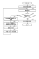
- FIG. 4 is a flowchart showing the image diagnosis support method.
- FIG. 5 is a diagram showing a specific example of a display image.
- FIG. 6 is a diagram showing a specific example of a display image.
- FIG. 7 is a diagram showing a specific example of a display image.
- FIG. 8 is a diagram showing a specific example of a display image.
- FIG. 9 is a diagram illustrating a first modified example of the embodiment.
- FIG. 10 is a diagram illustrating a second modification of the embodiment.
- FIG. 11 is a diagram illustrating a third modified example of the embodiment.
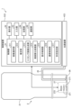
- FIGS. 1 and 2 are diagrams illustrating a configuration of an endoscope system 1 according to an embodiment.
- the endoscope system 1 corresponds to an image diagnosis support system according to the present invention.
- This endoscope system 1 is used in the medical field and is a system for observing the inside (the large intestine in this embodiment) of a subject PA (FIG. 1) who is a patient on a bed BD (FIG. 1).
- this endoscope system 1 includes an endoscope 2 and a processing device 3.
- the endoscope 2 corresponds to the imaging device according to the present invention.
- the endoscope 2 is a so-called flexible endoscope.
- a portion of the endoscope 2 is inserted into the body of the subject PA, images the inside of the body, and outputs an image signal generated by the imaging.
- the endoscope 2 comprises an insertion section 21, an operation section 22, a universal cord 23, and a connector section 24. Note that for ease of explanation, the operation section 22, universal cord 23, and connector section 24 are not shown in Figure 2.
- the insertion section 21 is at least partially flexible and is inserted into the body of the subject PA. As shown in FIG. 2, a light guide 25, an illumination lens 26, and an imaging section 27 are provided within the insertion section 21.
- the light guide 25 is routed from the insertion section 21 through the operation section 22 and the universal cord 23 to the connector section 24.
- One end of the light guide 25 is located at the tip portion inside the insertion section 21.
- the other end of the light guide 25 is located inside the processing device 3.
- the light guide 25 transmits light supplied from the light source device 4 inside the processing device 3 from the other end to one end.
- the illumination lens 26 faces one end of the light guide 25 inside the insertion portion 21. The illumination lens 26 irradiates the light transmitted by the light guide 25 onto the inside of the subject PA.
- the imaging unit 27 is provided at the tip of the insertion unit 21.
- the imaging unit 27 captures an image of the inside of the subject PA and outputs an image signal generated by the image capture.
- the imaging unit 27 includes a lens unit 271 and an image sensor 272.
- the lens unit 271 captures the return light (subject image) of the light irradiated from the illumination lens 26 into the body of the subject PA, and forms the subject image on the light receiving surface of the image sensor 272.
- the image sensor 272 is composed of a CCD (Charge Coupled Device) or CMOS (Complementary Metal Oxide Semiconductor) that receives the subject image and converts it into an electrical signal, and generates an image signal by capturing the subject image. Note that, hereinafter, the image signal generated by the imaging unit 27 is referred to as a captured image.
- CCD Charge Coupled Device
- CMOS Complementary Metal Oxide Semiconductor
- the operation unit 22 is connected to the base end portion of the insertion unit 21.
- the operation unit 22 receives various operations on the endoscope 2.
- the universal cord 23 extends from the operating section 22 in a direction different from the direction in which the insertion section 21 extends, and is a cord on which a signal line that electrically connects the imaging section 27 and the control device 5 in the processing device 3, a light guide 25, etc. are arranged.
- the connector portion 24 is provided at the end of the universal cord 23 and is detachably connected to the processing device 3.
- the processing device 3 includes a light source device 4 and a control device 5.
- the light source device 4 supplies light to the other end of the light guide 25 under the control of the control device 5.
- the light source device 4 emits white light as light in the first wavelength band.
- the light source device 4 may be configured to emit excitation light for exciting a fluorescent agent such as indocyanine green, narrow band light used in NBI (Narrow Band Imaging), etc. as light in a second wavelength band different from the first wavelength band.
- the control device 5 corresponds to the image diagnosis support device according to the present invention. As shown in FIG. 2, the control device 5 includes a control unit 51, a display unit 52, an input unit 53, a storage unit 54, and a communication unit 55.
- the control unit 51 includes a controller such as a CPU (Central Processing Unit) or an MPU (Micro Processing Unit), or an integrated circuit such as an ASIC (Application Specific Integrated Circuit) or an FPGA (Field Programmable Gate Array), and controls the operation of the entire endoscope system 1. As shown in FIG. 2, the control unit 51 has the functions of an image selection unit 511, an estimation unit 512, a trimmed image generation unit 513, an image quality improvement processing unit 514, a display control unit 515, and a communication control unit 516.
- a controller such as a CPU (Central Processing Unit) or an MPU (Micro Processing Unit), or an integrated circuit such as an ASIC (Application Specific Integrated Circuit) or an FPGA (Field Programmable Gate Array)
- the control unit 51 has the functions of an image selection unit 511, an estimation unit 512, a trimmed image generation unit 513, an image quality improvement processing unit 514, a display control unit 515, and a communication control unit 516.
- FIG. 3 is a diagram conceptually showing the function of the control unit 51.
- input image processing indicated by reference numeral 51B1 to which a captured image (endoscopic image) is input includes an image selection unit 511, a trimmed image generation unit 513, and an image quality improvement processing unit 514.
- estimation processing indicated by reference numeral 51B2 includes an estimation unit 512.
- display image generation indicated by reference numeral 51B3 includes a display control unit 515.
- control unit 51 as the image selection unit 511, the estimation unit 512, the trimmed image generation unit 513, the image quality improvement processing unit 514, the display control unit 515, and the communication control unit 516 will be described in the "Image diagnosis support method" described later.
- the display unit 52 corresponds to the notification unit according to the present invention.
- the display unit 52 is an LCD (Liquid Crystal Display) or an EL (Electro Luminescence) display, and displays the display image generated by the control unit 51 under the control of the control unit 51.
- the input unit 53 corresponds to the operation reception unit according to the present invention.
- This input unit 53 is configured using a keyboard, a mouse, a switch, a touch panel, etc., and receives user operations by a user such as a surgeon. Then, the input unit 53 outputs an operation signal corresponding to the user operation to the control unit 51.
- the storage unit 54 stores various programs executed by the control unit 51, as well as information necessary for the processing of the control unit 51.
- the communication unit 55 is connected to an external device so that communication can be performed.
- the communication unit 55 transmits predetermined information (data) to the external device under the control of the control unit 51.
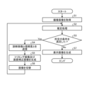
- FIG. 4 is a flowchart showing the image diagnosis support method.
- the image selection unit 511 acquires an image generated by the imaging unit 27 capturing a return light (subject image) of the white light from inside the subject PA while the light source device 4 is irradiating the inside of the subject PA (step S1).
- the captured image corresponds to a first captured image according to the present invention.
- the image selection unit 511 selects the captured image as a diagnostic image and inputs the diagnostic image to the estimation unit 512.
- the estimation unit 512 After step S1, the estimation unit 512 performs estimation processing on the diagnostic image using the trained model for estimation processing to estimate diagnostic candidate regions that are diagnostic candidates for each specified region in the diagnostic image, and outputs the reliability of the diagnostic candidate regions (step S2).
- the reliability of a diagnostic candidate region is a value indicating the level of reliability. Specifically, the reliability is a value that indicates the accuracy of image recognition in the diagnostic candidate region, and can also be considered as an index that indicates the probability that the object in the image is predicted to belong to a specific class. From the reliability of the diagnostic candidate region, it is possible to determine whether the object has been accurately recognized in the region.
- the trained model for estimation processing corresponds to the trained model according to the present invention.
- This trained model for estimation processing is stored in advance in the storage unit 54.
- the trained model for estimation processing is a trained model obtained by repeatedly executing a training process on the trained model using multiple sets of training images and teacher data, each set being a training image and teacher data.
- the training images are images captured inside a living body.
- the teacher data is data annotated with the classification class, correct position, and size of lesions and the like in the training images.
- the trained model used in the training process is, for example, a CNN (Convolutional Neural Network).
- the trained model for estimation processing includes a weight file (learning parameters) having weight values and bias values for each layer of the CNN.
- the neural network used in the learning process to generate a trained model for estimation processing is not limited to CNN, and other neural networks may be used.
- neural networks such as DNN (Deep Neural Network), Transformer, and GAN (Generative Adversarial Network) may be used as appropriate.
- various well-known learning algorithms may be used as machine learning algorithms in neural networks. For example, a supervised learning algorithm using backpropagation may be used.
- the image selection unit 511 determines whether a predetermined condition has been satisfied a predetermined number of times or for a predetermined period of time based on the reliability of the diagnostic candidate region output from the estimation unit 512 in step S2 (step S3).
- the predetermined condition is that a part of the diagnostic image contains a "region that may be an abnormal part."
- a region that may be an abnormal region refers to a region whose reliability is less than a first threshold and is equal to or greater than a second threshold lower than the first threshold.
- a "region that is a normal region” described below refers to a region whose reliability is less than the second threshold.
- a “region that is an abnormal region” described below refers to a region whose reliability is equal to or greater than the first threshold.
- Normal estimation processing estimates whether an area is normal or abnormal using one threshold. Specifically, if the reliability of the area is equal to or greater than the first threshold, it is determined to be an "abnormal area,” and if the reliability of the area is less than the first threshold, it is determined to be a "normal area.” In other words, areas that are less than the first threshold are determined to be "normal areas" regardless of the value. On the other hand, the estimation processing may overlook areas that are less than the first threshold but have a reliability close to the first threshold, that is, "areas that were determined to be normal but may be abnormal.” For example, there is a possibility that accurate estimation processing could not be performed due to low quality of the image input to the estimation processing. In that case, the area will be overlooked even though it was originally an abnormal area.
- a second threshold that is smaller than the first threshold is set. If the reliability of the area is less than the first threshold but equal to or greater than the second threshold, it is determined to be a "possible abnormal area," and the estimation processing is performed by changing the characteristics of the image input to the estimation processing.
- the communication control unit 516 causes the communication unit 55 to transmit the diagnostic image including the "areas that may be abnormal" and the reliability of each of the specified areas in the diagnostic image to an external device (step S4).
- step S5 the control unit 51 (trimmed image generating unit 513 and image quality improvement processing unit 514) generates a trimmed image and an image quality correction image (step S5).
- the captured image acquired in step S1 and the trimmed image and image quality correction image generated in step S5 correspond to "multiple images that include the same subject and have been subjected to different processes" according to the present invention.
- the trimmed image generation unit 513 generates a trimmed image by enlarging an area in the diagnostic image that includes a "potentially abnormal area.”
- the image quality improvement processing unit 514 also performs image quality improvement processing on the trimmed image using a trained model for image quality improvement processing, thereby generating a high-image-quality corrected image that looks as if it had been generated by an endoscope that generates high-image-quality captured images (hereinafter referred to as a high-image-quality endoscope).
- the image quality improvement processing may be performed by, in addition to the AI processing described above, for example, super-resolution processing or classical image processing (gradation processing, edge enhancement processing, frequency filter processing, etc.).
- the trained model for image quality improvement processing is stored in advance in the storage unit 54.
- the trained model for image quality improvement processing is a trained model obtained by repeatedly executing a training process on the trained model using multiple sets of training images and teacher data, each set being a training image and teacher data.
- the training images are images obtained by lowering the image quality of an image captured by a high-image-quality endoscope (hereinafter referred to as a high-image-quality image) to an image quality corresponding to a trimmed image.
- the teacher data is the high-image-quality image.
- the trained model used in the training process is, for example, a CNN.
- the trained model for image quality improvement processing includes a weight file (learning parameters) having weight values and bias values for each layer of the CNN.
- the neural network used in the learning process to generate a trained model for image quality improvement processing is not limited to CNN, and other neural networks may be used.
- various well-known learning algorithms can be used as the machine learning algorithm in the neural network.
- a supervised learning algorithm using the backpropagation method can be used.
- the image selection unit 511 switches the diagnostic image to one of the trimmed image or the image quality correction image generated in step S5 (step S6).
- the image selection unit 511 selects, as the diagnostic image, one of the trimmed images or the image quality correction images generated in step S5 that has been preset by a user operation on the input unit 53.
- the image selection unit 511 inputs the switched diagnostic image (trimmed image or image quality correction image) to the estimation unit 512. That is, the control unit 51 returns to step S2.
- FIG. 4 and the above explanation are used, but while the display image generation needs to be constantly running as a moving image, the image input to the estimation process can be a different image from the display image. That is, the image processing for the estimation process only needs to run in the background, and in reality, there is no need to branch and process as in FIG. 4.
- step S3 If it is determined that the predetermined condition is not satisfied (step S3: No), the display control unit 515 generates a display image to be displayed on the display unit 52 (step S7). Details of the display image will be described later in the section "Specific examples of display images.”
- FIG. 5 to 8 are diagrams showing specific examples of display images.
- the display control unit 515 generates a display image F1 shown in Fig. 5. Then, the display control unit 515 causes the display unit 52 to display the display image F1.
- the display image F1 includes an observation position image F11 and a diagnostic image F12.
- the observation position image F11 is an image in which the current observation position (the tip position of the insertion portion 21) OP is superimposed on an image showing the shape of the object to be observed (the large intestine in this embodiment).
- the diagnostic image F12 is an image (a captured image, a cropped image, or an image quality correction image) selected as a diagnostic image by the image selection unit 511. That is, when the diagnostic image is switched by the image selection unit 511 (step S6), the display control unit 515 switches the diagnostic image F12 on the display image F1 to the switched diagnostic image. Furthermore, if the estimation process determines that there is an "abnormal area" in the diagnostic image F12, the display control unit 515 superimposes identification information F13 (FIG. 5) that distinguishes the area corresponding to the "abnormal area” from other areas on the diagnostic image F12. That is, the display control unit 515 corresponds to the notification control unit according to the present invention.
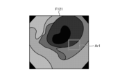
- the diagnostic image F121 shown in FIG. 6 is a captured image that is determined to satisfy the predetermined conditions in step S3.
- area Ar1 is a "region that may be an abnormal area.”
- a cropped image (or image quality correction image) F122 (FIG. 7) is generated by enlarging area Ar2 including area Ar1 (step S5).
- the cropped image (or image quality correction image) F122 is selected as the diagnostic image (step S6) and input to the estimation unit 512.
- the diagnostic image F12 of the display image F1 is switched to the cropped image (or image quality correction image) F122.
- the display control unit 515 then causes the display unit 52 to display the display image F2, for example.
- the control unit 51 stores the diagnostic image F12 in the storage unit 54 in sequence.
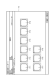
- the display control unit 515 in response to a user operation on the input unit 53, the display control unit 515 generates a display image F2 that displays a list of thumbnail images FT1 to FT9 of the multiple diagnostic images F12 stored in the storage unit .
- the image selection unit 511 selects, as a diagnostic image, one of the captured image acquired in step S1 and the trimmed image and image quality correction image generated in step S5, based on the reliability of the diagnostic candidate region. Then, the image selection unit 511 inputs the diagnostic image to the estimation unit 512. Therefore, according to the control device 5 of this embodiment, high-quality images can be input to the estimation unit 512, and diagnostic candidate areas such as lesions can be accurately estimated, thereby providing images suitable for diagnosis.
- the image input to the estimation process is appropriately and adaptively switched according to the reliability output by the estimation process, making it possible to improve the accuracy of the estimation process without re-learning, even in situations where the input image changes to an image unsuitable for the estimation process.
- the display control unit 515 superimposes, on the diagnostic image F12, identification information F13 that distinguishes the area corresponding to the "area that is abnormal" from other areas. Therefore, a user such as an operator can make an appropriate diagnosis based on the image in which the identification information F13 is superimposed on the diagnostic image F12.
- the communication control unit 516 causes the communication unit 55 to transmit a diagnostic image including "areas that may be abnormal" and the reliability of each specified area in the diagnostic image to an external device (step S4). Therefore, by performing a new learning process in the external device using the diagnostic image, it is possible to generate a new trained model for estimation processing that enables lesions, etc. to be estimated with high accuracy.
- the image selection unit 511 determines whether or not a specified condition has been satisfied a specified number of times or for a specified period of time based on the reliability of the diagnostic candidate region output from the estimation unit 512 in step S2. Therefore, when it is erroneously determined that a predetermined condition is satisfied only once, the diagnostic image is not immediately switched, and erroneous detection can be suppressed.
- the image diagnosis support device according to the present invention is mounted on the endoscope system 1 in which the insertion section 21 is configured by a flexible endoscope, but the present invention is not limited to this.
- the image diagnosis support device according to the present invention may be mounted on an endoscope system in which the insertion section 21 is configured by a rigid endoscope.
- the image diagnosis support device may be mounted on a medical observation system such as a surgical microscope (see, for example, JP 2016-42981 A) that enlarges and observes a predetermined field of view area inside a subject (inside a living body) or on a subject's surface (surface of a living body).
- a medical observation system such as a surgical microscope (see, for example, JP 2016-42981 A) that enlarges and observes a predetermined field of view area inside a subject (inside a living body) or on a subject's surface (surface of a living body).
- the “multiple images including the same subject and on which different processes have been performed” may include at least two of the captured image obtained in step S1, the cropped image and image quality correction image generated in step S5, and the second captured image described below.
- the second captured image is an image generated by the imaging unit 27 capturing the return light (fluorescence, etc.) of the second wavelength band light from the light source device 4 when the light source device 4 irradiates the inside of the subject PA.
- the display unit 52 is used as the notification unit according to the present invention, but this is not limiting, and an audio output unit such as a speaker that outputs audio may also be used as the notification unit according to the present invention.
- the predetermined condition according to the present invention is that a part of the diagnostic image has a "region that may be abnormal,” but this is not limited to this.
- the predetermined condition according to the present invention may be that a part of the diagnostic image has a "region that may be abnormal,” and that the diagnostic image does not have an "region that is abnormal.”
- FIG. 9 is a diagram for explaining the first modified example of the embodiment. Specifically, FIG. 9 corresponds to FIG. As shown in FIG. 9, in the control unit 51 according to the present modified example 1, a permission/denial setting unit 517 is added to the control unit 51 explained in the above embodiment.
- the image selection unit 511 in this modification 1 selects the image selected by the user operation to select a captured image or a trimmed image (or an image quality corrected image) on the input unit 53 as a diagnostic image.
- the permission/prohibition setting section 517 sets the state of the image selection section 511 to a permission state or a prohibition state according to a user operation on the input section 53 , as shown below.
- the permitted state is a state in which the image selection unit 511 is permitted to select a diagnostic image in response to the above-mentioned user operation. That is, in the permitted state, the image selection unit 511 selects an image selected by the user operation as a diagnostic image.
- the prohibited state is a state in which the image selection unit 511 is prohibited from selecting a diagnostic image in response to the above-mentioned user operation. That is, in the prohibited state, even if a captured image or a trimmed image (or an image quality correction image) is selected by the user operation, the image selection unit 511 does not select the image selected by the user operation as a diagnostic image.
- Fig. 10 is a diagram for explaining the second modified example of the embodiment. Specifically, Fig. 10 corresponds to Fig. 4 .
- the storage unit 54 according to the second modification stores the following first to third learning parameters.
- the first learning parameters correspond to the captured image acquired in step S1, and are learning parameters of a trained model for estimation processing used when performing estimation processing on the captured image.
- the second learning parameters correspond to the cropped image generated in step S5, and are learning parameters of the trained model for estimation processing that is used when performing estimation processing on the cropped image.
- the third learning parameter corresponds to the image quality corrected image generated in step S5, and is a learning parameter of the trained model for estimation processing used when performing estimation processing on the image quality corrected image.
- the estimation unit 512 executes estimation processing on an input diagnostic image by using a learning parameter corresponding to the input diagnostic image among the first to third learning parameters stored in the storage unit 54. Therefore, by using the learning parameter corresponding to the input diagnostic image, it is possible to estimate a lesion or the like with even greater accuracy.
- Fig. 11 is a diagram for explaining the third modified example of the embodiment. Specifically, Fig. 11 corresponds to Fig. 4 .
- the memory unit 54 according to the third modified example stores the first to third trained models shown below.
- the first trained model corresponds to the captured image acquired in step S1 and is a trained model for estimation processing used when performing estimation processing on the captured image.
- the third trained model corresponds to the image quality corrected image generated in step S5, and is a trained model for estimation processing used when performing estimation processing on the image quality corrected image.
- step S2 the estimation unit 512 performs estimation processing on the input diagnostic image using a trained model for estimation processing that corresponds to the input diagnostic image, among the first to third trained models stored in the storage unit 54. That is, when the input diagnostic image is a captured image acquired in step S1, the estimation unit 512 performs estimation processing on the captured image using the first trained model. Furthermore, when the diagnostic image is switched to a cropped image or an image quality corrected image in step S6, the estimation unit 512 switches the trained model for estimation processing from the first trained model to the second trained model or the third trained model (step S9). Then, the estimation unit 512 performs estimation processing on the cropped image or the image quality corrected image using the second trained model or the third trained model.
- the estimation unit 512 executes estimation processing on an input diagnostic image using a trained model for estimation processing corresponding to the input diagnostic image, among the first to third trained models stored in the storage unit 54. Therefore, by using the trained model for estimation processing corresponding to the input diagnostic image, it is possible to estimate a lesion or the like with even greater accuracy.
Landscapes
- Engineering & Computer Science (AREA)
- Health & Medical Sciences (AREA)
- Medical Informatics (AREA)
- Public Health (AREA)
- General Health & Medical Sciences (AREA)
- Biomedical Technology (AREA)
- Nuclear Medicine, Radiotherapy & Molecular Imaging (AREA)
- Radiology & Medical Imaging (AREA)
- Pathology (AREA)
- Physics & Mathematics (AREA)
- Epidemiology (AREA)
- Primary Health Care (AREA)
- Life Sciences & Earth Sciences (AREA)
- Computer Vision & Pattern Recognition (AREA)
- Theoretical Computer Science (AREA)
- Data Mining & Analysis (AREA)
- Databases & Information Systems (AREA)
- General Physics & Mathematics (AREA)
- Quality & Reliability (AREA)
- Surgery (AREA)
- Optics & Photonics (AREA)
- Biophysics (AREA)
- Heart & Thoracic Surgery (AREA)
- Molecular Biology (AREA)
- Animal Behavior & Ethology (AREA)
- Veterinary Medicine (AREA)
- Endoscopes (AREA)
- Image Analysis (AREA)
Priority Applications (4)
| Application Number | Priority Date | Filing Date | Title |
|---|---|---|---|
| CN202380099668.3A CN121398735A (zh) | 2023-07-05 | 2023-07-05 | 图像诊断辅助装置、图像诊断辅助系统以及图像诊断辅助方法 |
| JP2025530906A JPWO2025009124A1 (https=) | 2023-07-05 | 2023-07-05 | |
| PCT/JP2023/025015 WO2025009124A1 (ja) | 2023-07-05 | 2023-07-05 | 画像診断支援装置、画像診断支援システム、及び画像診断支援方法 |
| US19/416,787 US20260100281A1 (en) | 2023-07-05 | 2025-12-11 | Image diagnosis assistance apparatus, image diagnosis assistance system and image diagnosis assistance method |
Applications Claiming Priority (1)
| Application Number | Priority Date | Filing Date | Title |
|---|---|---|---|
| PCT/JP2023/025015 WO2025009124A1 (ja) | 2023-07-05 | 2023-07-05 | 画像診断支援装置、画像診断支援システム、及び画像診断支援方法 |
Related Child Applications (1)
| Application Number | Title | Priority Date | Filing Date |
|---|---|---|---|
| US19/416,787 Continuation US20260100281A1 (en) | 2023-07-05 | 2025-12-11 | Image diagnosis assistance apparatus, image diagnosis assistance system and image diagnosis assistance method |
Publications (1)
| Publication Number | Publication Date |
|---|---|
| WO2025009124A1 true WO2025009124A1 (ja) | 2025-01-09 |
Family
ID=94171318
Family Applications (1)
| Application Number | Title | Priority Date | Filing Date |
|---|---|---|---|
| PCT/JP2023/025015 Ceased WO2025009124A1 (ja) | 2023-07-05 | 2023-07-05 | 画像診断支援装置、画像診断支援システム、及び画像診断支援方法 |
Country Status (4)
| Country | Link |
|---|---|
| US (1) | US20260100281A1 (https=) |
| JP (1) | JPWO2025009124A1 (https=) |
| CN (1) | CN121398735A (https=) |
| WO (1) | WO2025009124A1 (https=) |
Citations (6)
| Publication number | Priority date | Publication date | Assignee | Title |
|---|---|---|---|---|
| JP2016042981A (ja) | 2014-08-21 | 2016-04-04 | ソニー・オリンパスメディカルソリューションズ株式会社 | 医療用観察装置および医療用観察システム |
| WO2020090002A1 (ja) * | 2018-10-30 | 2020-05-07 | オリンパス株式会社 | 内視鏡システム及び内視鏡システムに用いる画像処理装置及び画像処理方法 |
| JP6952214B2 (ja) | 2019-03-28 | 2021-10-20 | Hoya株式会社 | 内視鏡用プロセッサ、情報処理装置、内視鏡システム、プログラム及び情報処理方法 |
| WO2021229684A1 (ja) * | 2020-05-12 | 2021-11-18 | オリンパス株式会社 | 画像処理システム、内視鏡システム、画像処理方法及び学習方法 |
| WO2022071413A1 (ja) * | 2020-10-02 | 2022-04-07 | 富士フイルム株式会社 | 画像処理装置、内視鏡システム、画像処理装置の作動方法、及び画像処理装置用プログラム |
| WO2022181748A1 (ja) * | 2021-02-26 | 2022-09-01 | 富士フイルム株式会社 | 医療画像処理装置、内視鏡システム、医療画像処理方法、及び医療画像処理プログラム |
-
2023
- 2023-07-05 CN CN202380099668.3A patent/CN121398735A/zh active Pending
- 2023-07-05 JP JP2025530906A patent/JPWO2025009124A1/ja active Pending
- 2023-07-05 WO PCT/JP2023/025015 patent/WO2025009124A1/ja not_active Ceased
-
2025
- 2025-12-11 US US19/416,787 patent/US20260100281A1/en active Pending
Patent Citations (6)
| Publication number | Priority date | Publication date | Assignee | Title |
|---|---|---|---|---|
| JP2016042981A (ja) | 2014-08-21 | 2016-04-04 | ソニー・オリンパスメディカルソリューションズ株式会社 | 医療用観察装置および医療用観察システム |
| WO2020090002A1 (ja) * | 2018-10-30 | 2020-05-07 | オリンパス株式会社 | 内視鏡システム及び内視鏡システムに用いる画像処理装置及び画像処理方法 |
| JP6952214B2 (ja) | 2019-03-28 | 2021-10-20 | Hoya株式会社 | 内視鏡用プロセッサ、情報処理装置、内視鏡システム、プログラム及び情報処理方法 |
| WO2021229684A1 (ja) * | 2020-05-12 | 2021-11-18 | オリンパス株式会社 | 画像処理システム、内視鏡システム、画像処理方法及び学習方法 |
| WO2022071413A1 (ja) * | 2020-10-02 | 2022-04-07 | 富士フイルム株式会社 | 画像処理装置、内視鏡システム、画像処理装置の作動方法、及び画像処理装置用プログラム |
| WO2022181748A1 (ja) * | 2021-02-26 | 2022-09-01 | 富士フイルム株式会社 | 医療画像処理装置、内視鏡システム、医療画像処理方法、及び医療画像処理プログラム |
Also Published As
| Publication number | Publication date |
|---|---|
| JPWO2025009124A1 (https=) | 2025-01-09 |
| CN121398735A (zh) | 2026-01-23 |
| US20260100281A1 (en) | 2026-04-09 |
Similar Documents
| Publication | Publication Date | Title |
|---|---|---|
| CN100577088C (zh) | 图像显示装置 | |
| CN113543694B (zh) | 医用图像处理装置、处理器装置、内窥镜系统、医用图像处理方法、及记录介质 | |
| JP7278202B2 (ja) | 画像学習装置、画像学習方法、ニューラルネットワーク、及び画像分類装置 | |
| JP2024153783A (ja) | 画像処理装置 | |
| JP7143504B2 (ja) | 医用画像処理装置、プロセッサ装置、内視鏡システム、医用画像処理装置の作動方法及びプログラム | |
| JP7451680B2 (ja) | 処理システム、画像処理方法、学習方法及び処理装置 | |
| CN115066196B (zh) | 医用图像处理装置、内窥镜系统、医用图像处理方法及记录介质 | |
| CN110536629B (zh) | 手术图像处理设备、图像处理方法和手术系统 | |
| JP7387859B2 (ja) | 医用画像処理装置、プロセッサ装置、内視鏡システム、医用画像処理装置の作動方法及びプログラム | |
| WO2019138772A1 (ja) | 画像処理装置、プロセッサ装置、画像処理方法、及びプログラム | |
| CN116777786A (zh) | 基于内窥镜成像的视频图像生成方法和装置及内窥镜系统 | |
| WO2022186109A1 (ja) | 医療画像処理装置、内視鏡システム、医療画像処理方法、及び医療画像処理プログラム | |
| JP7225417B2 (ja) | 医療画像処理システム及び医療画像処理装置の作動方法 | |
| JP7774610B2 (ja) | 医療画像処理装置、内視鏡システム、医療画像処理方法、医療画像処理プログラム、及び記録媒体 | |
| US20250194910A1 (en) | Endoscope control device, method of changing wavelength characteristics of illumination light, and information storage medium | |
| WO2025009124A1 (ja) | 画像診断支援装置、画像診断支援システム、及び画像診断支援方法 | |
| WO2022191058A1 (ja) | 内視鏡画像処理装置、方法及びプログラム | |
| WO2019146079A1 (ja) | 内視鏡画像処理装置、内視鏡画像処理方法及びプログラム | |
| US12604076B2 (en) | Endoscope system, control method, and program | |
| WO2021033215A1 (ja) | 内視鏡用プロセッサ、内視鏡システム、情報処理装置、プログラム及び情報処理方法 | |
| WO2022186111A1 (ja) | 医用画像処理装置、医用画像処理方法、及びプログラム | |
| CN118647300A (zh) | 信息输出方法以及信息输出装置 | |
| WO2025009147A1 (ja) | 画像診断支援装置、画像診断支援システム、及び画像診断支援方法 | |
| JPWO2020009127A1 (ja) | 医療用観察システム、医療用観察装置、及び医療用観察装置の駆動方法 | |
| CN105899123B (zh) | 用于内窥镜的视频处理器和具有该视频处理器的内窥镜系统 |
Legal Events
| Date | Code | Title | Description |
|---|---|---|---|
| 121 | Ep: the epo has been informed by wipo that ep was designated in this application |
Ref document number: 23944372 Country of ref document: EP Kind code of ref document: A1 |
|
| ENP | Entry into the national phase |
Ref document number: 2025530906 Country of ref document: JP Kind code of ref document: A |
|
| WWE | Wipo information: entry into national phase |
Ref document number: 2025530906 Country of ref document: JP |
|
| WWE | Wipo information: entry into national phase |
Ref document number: 2023944372 Country of ref document: EP |
|
| NENP | Non-entry into the national phase |
Ref country code: DE |
|
| ENP | Entry into the national phase |
Ref document number: 2023944372 Country of ref document: EP Effective date: 20260205 |