WO2025005708A1 - 저전력 웨이크업 수신기를 이용하여 무선 통신을 수행하는 방법 및 장치 - Google Patents
저전력 웨이크업 수신기를 이용하여 무선 통신을 수행하는 방법 및 장치 Download PDFInfo
- Publication number
- WO2025005708A1 WO2025005708A1 PCT/KR2024/009063 KR2024009063W WO2025005708A1 WO 2025005708 A1 WO2025005708 A1 WO 2025005708A1 KR 2024009063 W KR2024009063 W KR 2024009063W WO 2025005708 A1 WO2025005708 A1 WO 2025005708A1
- Authority
- WO
- WIPO (PCT)
- Prior art keywords
- terminal
- timer
- wake
- signal
- monitoring
- Prior art date
- Legal status (The legal status is an assumption and is not a legal conclusion. Google has not performed a legal analysis and makes no representation as to the accuracy of the status listed.)
- Ceased
Links
Images





Classifications
-
- Y—GENERAL TAGGING OF NEW TECHNOLOGICAL DEVELOPMENTS; GENERAL TAGGING OF CROSS-SECTIONAL TECHNOLOGIES SPANNING OVER SEVERAL SECTIONS OF THE IPC; TECHNICAL SUBJECTS COVERED BY FORMER USPC CROSS-REFERENCE ART COLLECTIONS [XRACs] AND DIGESTS
- Y02—TECHNOLOGIES OR APPLICATIONS FOR MITIGATION OR ADAPTATION AGAINST CLIMATE CHANGE
- Y02D—CLIMATE CHANGE MITIGATION TECHNOLOGIES IN INFORMATION AND COMMUNICATION TECHNOLOGIES [ICT], I.E. INFORMATION AND COMMUNICATION TECHNOLOGIES AIMING AT THE REDUCTION OF THEIR OWN ENERGY USE
- Y02D30/00—Reducing energy consumption in communication networks
- Y02D30/70—Reducing energy consumption in communication networks in wireless communication networks
Definitions
- the present embodiments propose a method and apparatus for performing wireless communication using a low-power wake-up receiver in a next-generation wireless access network (in this disclosure, “5G”, “NR [New Radio]”, “5G-Advanced”, “6G” or a subsequent 3GPP wireless access network).
- a next-generation wireless access network in this disclosure, “5G”, “NR [New Radio]”, “5G-Advanced”, “6G” or a subsequent 3GPP wireless access network.
- 3GPP continues to research and develop wireless communication technologies.
- energy efficiency of the terminal is also a very important consideration.
- terminals may need to be charged frequently depending on the individual's usage time. Designing for extended battery life of terminals is essential for improving energy efficiency and improving user experience. Energy efficiency is important for terminals that do not have a continuous energy source.
- Power consumption may vary depending on the configured wake-up period length. However, if DRX cycles with large values are used to meet battery life requirements, this may result in high latency, and may not be suitable for services that require both long battery life and low latency.
- Embodiments of the present disclosure can provide a method and device for performing wireless communication using a low-power wake-up receiver.
- the present embodiments may provide a method for a terminal to perform wireless communication using a low power wakeup receiver (LR), the method including: receiving configuration information for a low power wakeup operation; monitoring a wakeup signal (WUS) through the low power wakeup receiver based on the configuration information; starting a predetermined timer when the wakeup signal is received; and monitoring a downlink control channel through a transceiver when the timer is started.
- LR low power wakeup receiver
- the present embodiments can provide a method for a base station to control an operation of a terminal performing wireless communication using a low-power wake-up receiver, the method including the steps of transmitting configuration information for a low-power wake-up operation, transmitting a wake-up signal (WUS) to the terminal based on the configuration information when downlink data to be transmitted to the terminal is confirmed, and transmitting a downlink control channel for transmitting the downlink data.
- WUS wake-up signal
- the present embodiments provide a terminal for performing wireless communication using a low power wakeup receiver (LR), the terminal including a low power wakeup receiver, a transceiver, and a controller for controlling operations of the low power wakeup receiver and the transceiver, wherein the controller receives configuration information for a low power wakeup operation, monitors a wakeup signal (WUS) through the low power wakeup receiver based on the configuration information, starts a predetermined timer when the wakeup signal is received, and monitors a downlink control channel through the transceiver when the timer is started.
- LR low power wakeup receiver
- WUS wakeup signal
- the present embodiments provide a base station for controlling the operation of a terminal performing wireless communication using a low-power wake-up receiver, the base station including a transmitter, a receiver, and a controller for controlling the operations of the transmitter and the receiver, wherein the controller transmits configuration information for a low-power wake-up operation, and when downlink data to be transmitted to the terminal is confirmed, transmits a wakeup signal (WUS) to the terminal based on the configuration information, and transmits a downlink control channel for transmitting the downlink data.
- WUS wakeup signal
- a method and device for performing wireless communication using a low-power wake-up receiver capable of performing a wake-up operation that consumes power efficiently can be provided.
- the terminal when a terminal that wants to minimize power consumption monitors downlink signals using only an ultra-low-power receiver separate from a main radio (MR) transceiver such as NR, the terminal can minimize power consumption by recognizing that the terminal has been awakened due to unintended WUS reception from the base station and quickly terminating monitoring with the MR transceiver.
- MR main radio
- the terminal and base station can quickly recognize a receiver mode mismatch situation that may occur between the terminal and the base station, the communication disconnection problem between the terminal and the base station can be solved.
- FIG. 1 is a diagram briefly illustrating the structure of an NR wireless communication system to which the present embodiment can be applied.
- FIG. 2 is a drawing for explaining a frame structure in an NR system to which the present embodiment can be applied.
- FIG. 3 is a diagram for explaining a resource grid supported by a wireless access technology to which the present embodiment can be applied.
- FIG. 4 is a diagram for explaining a bandwidth part supported by a wireless access technology to which the present embodiment can be applied.
- FIG. 5 is a diagram exemplarily illustrating a synchronization signal block in a wireless access technology to which the present embodiment can be applied.
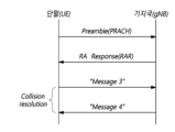
- FIG. 6 is a diagram for explaining a random access procedure in a wireless access technology to which the present embodiment can be applied.
- Figure 7 is a drawing for explaining CORESET.
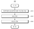
- FIG. 9 is a diagram illustrating a procedure for a base station to control the operation of a terminal performing wireless communication using a low-power wake-up receiver according to one embodiment.
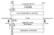
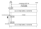
- FIG. 10 is a diagram for explaining a low-power wake-up operation using a timer of a terminal according to one embodiment.
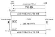
- FIG. 11 is a diagram for explaining a low-power wake-up operation using a timer of a terminal and a base station according to one embodiment.
- FIG. 12 is a diagram for explaining a low-power wake-up operation when a timer of a terminal expires according to one embodiment.
- FIG. 13 is a diagram for explaining a low-power wake-up operation when the timer of a terminal and a base station expires according to one embodiment.
- FIG. 14 is a diagram for explaining a low-power wake-up operation according to an LR mode switching instruction according to one embodiment.
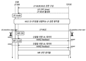
- FIG. 15 is a diagram for explaining a low-power wake-up operation when a timer according to one embodiment is set as a timer for entering LR mode.
- Fig. 17 is a diagram showing the configuration of a base station according to another embodiment.
- first, second, A, B, (a), (b), etc. may be used. These terms are only intended to distinguish the components from other components, and the nature, order, sequence, or number of the components are not limited by the terms.
- temporal chronological relationship or the chronological flow relationship when the temporal chronological relationship or the chronological flow relationship is described as “after”, “following”, “next to”, or “before”, it can also include cases where it is not continuous, as long as “immediately” or “directly” is not used.
- the numerical value or its corresponding information may be interpreted as including an error range that may occur due to various factors (e.g., process factors, internal or external impact, noise, etc.).
- the wireless communication system in this specification means a system for providing various communication services, such as voice and data packets, using wireless resources, and may include a terminal, a base station, or a core network.
- the embodiments disclosed below can be applied to wireless communication systems using various wireless access technologies.
- the embodiments can be applied to various wireless access technologies such as CDMA (code division multiple access), FDMA (frequency division multiple access), TDMA (timedivision multiple access), OFDMA (orthogonal frequency division multiple access), SC-FDMA (singlecarrier frequency division multiple access), or NOMA (non-orthogonal multiple access).
- the wireless access technology may mean not only a specific access technology, but also each generational communication technology established by various communication agreement organizations such as 3GPP, 3GPP2, WiFi, Bluetooth, IEEE, and ITU.
- CDMA can be implemented with a wireless technology such as UTRA (universal terrestrial radio access) or CDMA2000.
- TDMA can be implemented with a wireless technology such as GSM (global system for mobile communications)/GPRS (general packet radio service)/EDGE (enhanced datarates for GSM evolution).
- OFDMA can be implemented in wireless technologies such as IEEE (Institute of Electrical and Electronic Engineers) 802.11 (Wi-Fi), IEEE 802.16 (WiMAX), IEEE 802-20, E-UTRA (evolved UTRA), etc.
- IEEE 802.16m is an evolution of IEEE 802.16e and provides backward compatibility with systems based on IEEE 802.16e.
- UTRA is a part of UMTS (universal mobile telecommunications system).
- the terminal in this specification is a comprehensive concept meaning a device including a wireless communication module that performs communication with a base station in a wireless communication system, and should be interpreted as a concept including not only UE (User Equipment) in WCDMA, LTE, NR, HSPA, and IMT-2020 (5G or New Radio), but also MS (Mobile Station), UT (User Terminal), SS (Subscriber Station), and wireless device in GSM.
- the terminal may be a user portable device such as a smart phone depending on the usage type, and in a V2X communication system, it may mean a vehicle, a device including a wireless communication module in a vehicle, etc.
- a Machine Type Communication system it may mean an MTC terminal, M2M terminal, URLLC terminal, etc. equipped with a communication module to perform machine type communication.
- the base station or cell in this specification refers to an end that communicates with a terminal in terms of a network, and includes a Node-B, an evolved Node-B (eNB), a gNode-B (gNB), a Low Power Node (LPN), a sector, a site, various types of antennas, a Base Transceiver System (BTS), an Access Point, points (e.g., a transmission point, a reception point, a transceiver point), a relay node, a mega cell, a macro cell, a micro cell, a pico cell, a femto cell, a Remote Radio Head (RRH), a Radio Unit (RU), a small cell, and various coverage areas.
- a cell may mean a BWP (Bandwidth Part) in a frequency domain.
- a serving cell may mean an Activation BWP of a terminal.
- the various cells listed above have a base station that controls one or more cells, so the base station can be interpreted in two meanings. 1) It can be a device itself that provides a mega cell, a macro cell, a micro cell, a pico cell, a femto cell, or a small cell in relation to a wireless area, or 2) It can indicate the wireless area itself. In 1), all devices that provide a given wireless area are controlled by the same entity or interact to cooperatively configure the wireless area are all indicated as a base station. Depending on the configuration method of the wireless area, a point, a transceiver point, a transmission point, a reception point, etc. become an embodiment of a base station. In 2), the wireless area itself that receives or transmits a signal from the perspective of a user terminal or a neighboring base station can also be indicated as a base station.
- a cell may mean a component carrier having coverage of a signal transmitted from a transmission/reception point or coverage of a signal transmitted from a transmission/reception point, or the transmission/reception point itself.
- Uplink refers to a method of transmitting and receiving data from a terminal to a base station
- downlink refers to a method of transmitting and receiving data from a base station to a terminal
- Downlink may refer to communication or a communication path from multiple transmission/reception points to a terminal
- uplink may refer to communication or a communication path from a terminal to multiple transmission/reception points.
- the transmitter in the downlink, the transmitter may be part of the multiple transmission/reception points, and the receiver may be part of the terminal.
- the transmitter in the uplink, the transmitter may be part of the terminal, and the receiver may be part of the multiple transmission/reception points.
- Uplink and downlink transmit and receive control information through control channels such as PDCCH (Physical Downlink Control CHannel) and PUCCH (Physical Uplink Control CHannel), and transmit and receive data by configuring data channels such as PDSCH (Physical Downlink Shared CHannel) and PUSCH (Physical Uplink Shared CHannel).
- control channels such as PDCCH (Physical Downlink Control CHannel) and PUCCH (Physical Uplink Control CHannel)
- PDSCH Physical Uplink Shared CHannel
- PUSCH Physical Uplink Shared CHannel
- 3GPP After studying 4G (4th-Generation) communication technology, 3GPP develops 5G (5th-Generation) communication technology to meet the requirements of the next-generation wireless access technology of the ITU-R. Specifically, 3GPP develops LTE-A pro, which enhances LTE-Advanced technology to meet the requirements of the ITU-R, as a 5G communication technology, and NR, a new communication technology separate from 4G communication technology. Both LTE-A pro and NR refer to 5G communication technology, and in the following, 5G communication technology is explained with NR as the center, unless a specific communication technology is specified.
- the operating scenario in NR defines various operation scenarios by adding considerations for satellites, automobiles, and new verticals to the existing 4G LTE scenario, and supports the eMBB (Enhanced Mobile Broadband) scenario in terms of service, the mMTC (Massive Machine Communication) scenario that has high terminal density but is deployed over a wide area and requires low data rate and asynchronous access, and the URLLC (Ultra Reliability and Low Latency) scenario that requires high responsiveness and reliability and can support high-speed mobility.
- eMBB Enhanced Mobile Broadband
- mMTC Massive Machine Communication
- URLLC Ultra Reliability and Low Latency
- NR introduces a wireless communication system that applies new waveform and frame structure technologies, low latency technologies, ultra-high frequency band (mmWave) support technologies, and forward compatibility technologies.
- mmWave ultra-high frequency band
- the NR system presents various technological changes in terms of flexibility to provide forward compatibility. The main technological features of NR are explained below with reference to the drawings.
- Figure 1 is a schematic diagram illustrating the structure of an NR system to which the present embodiment can be applied.
- the NR system is divided into 5GC (5G Core Network) and NR-RAN parts, and the NG-RAN is composed of gNBs and ng-eNBs that provide user plane (SDAP/PDCP/RLC/MAC/PHY) and control plane (RRC) protocol termination for UE (User Equipment).
- the gNBs or the gNBs and ng-eNBs are interconnected via the Xn interface.
- the gNBs and ng-eNBs are each connected to the 5GC via the NG interface.
- the 5GC can be configured to include the AMF (Access and Mobility Management Function) that is in charge of the control plane such as terminal access and mobility control functions, and the UPF (User Plane Function) that is in charge of the control function for user data.
- AMF Access and Mobility Management Function
- UPF User Plane Function
- NR includes support for both frequency bands below 6 GHz (FR1, Frequency Range 1) and frequency bands above 6 GHz (FR2, Frequency Range 2).
- gNB refers to a base station that provides NR user plane and control plane protocol termination to terminals
- ng-eNB refers to a base station that provides E-UTRA user plane and control plane protocol termination to terminals.
- the base station described in this specification should be understood to encompass gNB and ng-eNB, and may also be used to refer to gNB or ng-eNB separately as needed.
- OFDM uses CP-OFDM waveforms with cyclic prefix for downlink transmission, and CP-OFDM or DFT-s-OFDM for uplink transmission.
- OFDM technology is easy to combine with MIMO (Multiple Input Multiple Output) and has the advantage of being able to use low-complexity receivers along with high frequency efficiency.
- MIMO Multiple Input Multiple Output
- the NR transmission numerology is determined based on the sub-carrier spacing and the cyclic prefix (CP), and is exponentially changed using the ⁇ value as an exponent value of 2 based on 15 kHz, as shown in Table 1 below.
- the numerology of NR can be divided into five types according to the subcarrier spacing. This is different from the subcarrier spacing of LTE, one of the 4G communication technologies, which is fixed to 15 kHz. Specifically, the subcarrier spacings used for data transmission in NR are 15, 30, 60, and 120 kHz, and the subcarrier spacings used for synchronization signal transmission are 15, 30, 12, and 240 kHz. In addition, the extended CP is applied only to the 60 kHz subcarrier spacing. Meanwhile, the frame structure in NR is defined as a frame with a length of 10 ms, which consists of 10 subframes with the same length of 1 ms.
- One frame can be divided into half frames of 5 ms, and each half frame includes 5 subframes.
- one subframe consists of one slot
- each slot consists of 14 OFDM symbols.
- FIG. 2 is a diagram for explaining a frame structure in an NR system to which the present embodiment can be applied.
- a slot is fixedly composed of 14 OFDM symbols in the case of a normal CP, but the length of the slot in the time domain may vary depending on the subcarrier spacing.
- a slot is composed of 1 ms, which is the same length as a subframe.
- a slot is composed of 14 OFDM symbols, but two slots can be included in one subframe with a length of 0.5 ms. That is, a subframe and a frame are defined with a fixed time length, and a slot is defined by the number of symbols, so the time length may vary depending on the subcarrier spacing.
- NR defines the basic unit of scheduling as a slot, and also introduces a mini-slot (or sub-slot, or non-slot based schedule) to reduce transmission delay in the wireless section.
- a mini-slot or sub-slot, or non-slot based schedule
- Using a wide subcarrier spacing reduces transmission delay in the wireless section because the length of one slot is shortened inversely.
- Mini-slots (or sub-slots) are for efficient support of URLLC scenarios, and scheduling is possible in units of 2, 4, and 7 symbols.
- NR defines uplink and downlink resource allocation at the symbol level within a single slot.
- a slot structure that can transmit HARQ ACK/NACK directly within a transmission slot is defined, and this slot structure is named and explained as a self-contained structure.
- NR is designed to support a total of 256 slot formats, of which 62 slot formats are used in 3GPP Rel-15. In addition, it supports a common frame structure that configures an FDD or TDD frame through various combinations of slots. For example, it supports a slot structure in which all symbols of a slot are set to downlink, a slot structure in which all symbols are set to uplink, and a slot structure in which downlink symbols and uplink symbols are combined. In addition, NR supports data transmission being distributed and scheduled to one or more slots. Therefore, a base station can inform a UE whether a slot is a downlink slot, an uplink slot, or a flexible slot using a slot format indicator (SFI). A base station can indicate a slot format by indicating an index of a table configured through UE-specific RRC signaling using SFI, and can also indicate it dynamically through DCI (Downlink Control Information) or statically or semi-statically through RRC.
- DCI Downlink Control Information
- antenna ports In relation to physical resources in NR, antenna ports, resource grids, resource elements, resource blocks, and bandwidth parts are considered.
- Antenna ports are defined such that the channel through which a symbol on an antenna port is carried can be inferred from the channel through which another symbol on the same antenna port is carried.
- Two antenna ports are said to be in a QC/QCL (quasi co-located or quasi co-location) relationship if large-scale properties of the channel through which a symbol on one antenna port is carried can be inferred from the channel through which a symbol on the other antenna port is carried.
- the large-scale properties include one or more of delay spread, Doppler spread, frequency shift, average received power, and received timing.
- FIG. 3 is a diagram for explaining a resource grid supported by a wireless access technology to which the present embodiment can be applied.
- a resource grid may exist for each numeral because NR supports multiple numerals in the same carrier.
- a resource grid may exist for each antenna port, subcarrier spacing, and transmission direction.
- a resource block consists of 12 subcarriers and is defined only in the frequency domain.
- a resource element consists of one OFDM symbol and one subcarrier. Therefore, as shown in Fig. 3, the size of one resource block can vary depending on the subcarrier spacing.
- NR defines "Point A", which serves as a common reference point for the resource block grid, common resource blocks, virtual resource blocks, etc.
- FIG. 4 is a diagram for explaining a bandwidth part supported by a wireless access technology to which the present embodiment can be applied.
- a bandwidth part can be designated within the carrier bandwidth for use by the terminal.
- a bandwidth part is linked to one numerology and consists of a subset of consecutive common resource blocks, and can be dynamically activated over time.
- a terminal is configured with up to four bandwidth parts for each of the uplink and downlink, and data is transmitted and received using the bandwidth part activated at a given time.
- the uplink and downlink bandwidth parts are set independently, and in the case of an unpaired spectrum, the bandwidth parts of the downlink and uplink are set as pairs so that they can share a center frequency to prevent unnecessary frequency re-tuning between downlink and uplink operations.
- a terminal performs cell search and random access procedures to connect to a base station and perform communication.
- Cell search is a procedure in which a terminal synchronizes to a cell of a corresponding base station, obtains a physical layer cell ID, and obtains system information using a synchronization signal block (SSB) transmitted by the base station.
- SSB synchronization signal block
- FIG. 5 is a diagram exemplarily illustrating a synchronization signal block in a wireless access technology to which the present embodiment can be applied.
- the SSB is composed of a primary synchronization signal (PSS) and a secondary synchronization signal (SSS), each of which occupies 1 symbol and 127 subcarriers, and a PBCH that spans 3 OFDM symbols and 240 subcarriers.
- PSS primary synchronization signal
- SSS secondary synchronization signal
- the terminal receives SSB by monitoring SSB in the time and frequency domain.
- SSB can be transmitted up to 64 times during 5ms. Multiple SSBs are transmitted with different transmission beams within 5ms, and the terminal performs detection assuming that SSBs are transmitted every 20ms based on a specific beam used for transmission.
- the number of beams that can be used for SSB transmission within 5ms can increase as the frequency band increases. For example, up to 4 SSB beams can be transmitted below 3GHz, up to 8 different beams can be used for SSB transmission in the frequency band of 3 to 6GHz, and up to 64 different beams can be used for SSB transmission in the frequency band of 6GHz or higher.
- SSB contains two in one slot, and the start symbol and repetition number within the slot are determined as follows depending on the subcarrier spacing.
- SSB unlike SS of conventional LTE, is not transmitted at the center frequency of the carrier bandwidth. That is, SSB can be transmitted even in a location other than the center of the system band, and multiple SSBs can be transmitted on the frequency domain when wideband operation is supported. Accordingly, the terminal monitors SSB using the synchronization raster, which is a candidate frequency location for monitoring SSB.
- the carrier raster and synchronization raster which are center frequency location information of the channel for initial access, are newly defined in NR, and the synchronization raster can support fast SSB search of the terminal because the frequency interval of the synchronization raster is set wider than that of the carrier raster.
- a terminal can obtain a MIB through a PBCH of an SSB.
- the MIB Master Information Block
- the MIB includes minimum information for the terminal to receive remaining system information (RMSI, Remaining Minimum System Information) broadcast by the network.
- the PBCH may include information on the position of a first DM-RS symbol in the time domain, information for the terminal to monitor SIB1 (e.g., SIB1 numerology information, information related to SIB1 CORESET, search space information, PDCCH related parameter information, etc.), offset information between a common resource block and an SSB (the absolute position of an SSB within a carrier is transmitted through SIB1), etc.
- the SIB1 numerology information is equally applied to some messages used in a random access procedure for accessing a base station after the terminal completes a cell search procedure.
- the numerology information of SIB1 may be applied to at least one of messages 1 to 4 for the random access procedure.
- the aforementioned RMSI may mean SIB1 (System Information Block 1), and SIB1 is broadcasted periodically (ex, 160 ms) in the cell.
- SIB1 includes information required for the terminal to perform an initial random access procedure, and is transmitted periodically through PDSCH.
- the terminal In order for the terminal to receive SIB1, it must receive numerology information used for transmitting SIB1 and CORESET (Control Resource Set) information used for scheduling SIB1 through PBCH.
- the terminal checks scheduling information for SIB1 using SI-RNTI in CORESET, and acquires SIB1 on PDSCH according to the scheduling information.
- the remaining SIBs except SIB1 may be transmitted periodically or may be transmitted according to the request of the terminal.
- FIG. 6 is a diagram for explaining a random access procedure in a wireless access technology to which the present embodiment can be applied.
- the terminal transmits a random access preamble for random access to the base station.
- the random access preamble is transmitted through PRACH.
- the random access preamble is transmitted to the base station through PRACH, which consists of consecutive radio resources in a specific slot that is repeated periodically.
- PRACH which consists of consecutive radio resources in a specific slot that is repeated periodically.
- BFR beam failure recovery
- a terminal receives a random access response to a transmitted random access preamble.
- the random access response may include a random access preamble identifier (ID), an UL Grant (uplink radio resource), a temporary C-RNTI (Temporary Cell - Radio Network Temporary Identifier) and a TAC (Time Alignment Command). Since one random access response may include random access response information for one or more terminals, the random access preamble identifier may be included to indicate to which terminal the included UL Grant, temporary C-RNTI and TAC are valid.
- the random access preamble identifier may be an identifier for a random access preamble received by a base station.
- the TAC may be included as information for the terminal to adjust uplink synchronization.
- the random access response may be indicated by a random access identifier on a PDCCH, i.e., an RA-RNTI (Random Access - Radio Network Temporary Identifier).
- the terminal that receives a valid random access response processes the information contained in the random access response and performs scheduled transmission to the base station. For example, the terminal applies TAC and stores a temporary C-RNTI. In addition, it transmits data stored in the terminal's buffer or newly generated data to the base station using the UL Grant. In this case, information that can identify the terminal must be included.
- the terminal receives a downlink message for contention resolution.
- the downlink control channel in NR is transmitted in a CORESET (Control Resource Set) with a length of 1 to 3 symbols, and transmits uplink/downlink scheduling information, SFI (Slot format Index), and TPC (Transmit Power Control) information.
- CORESET Control Resource Set
- SFI Slot format Index
- TPC Transmit Power Control
- CORESET Control Resource Set
- a terminal can decode control channel candidates using one or more search spaces in the CORESET time-frequency resources.
- a QCL (Quasi CoLocation) assumption is set for each CORESET, and this is used for the purpose of informing the characteristics of the analog beam direction in addition to the delay spread, Doppler spread, Doppler shift, and average delay, which are the characteristics assumed by the conventional QCL.
- Figure 7 is a drawing for explaining CORESET.
- a CORESET can exist in various forms within a carrier bandwidth within one slot, and a CORESET can consist of a maximum of three OFDM symbols in the time domain.
- a CORESET is defined as a multiple of six resource blocks up to the carrier bandwidth in the frequency domain.
- the first CORESET is indicated via MIB as part of the initial bandwidth part configuration to enable receiving additional configuration information and system information from the network.
- the terminal After establishing a connection with the base station, the terminal can receive and configure one or more CORESET information via RRC signaling.
- an arbitrary LTE operator could configure a bandwidth of a minimum of 1.4 MHz and a maximum of 20 MHz when configuring an LTE CC, and a normal LTE terminal supported a transmission/reception capability of 20 MHz bandwidth for an LTE CC.
- bandwidth parts BWPs, bandwidth part(s)
- segmented bandwidths are configured for any NR CC, and it is required to support flexible wider bandwidth operation through different bandwidth part configurations and activations for each terminal.
- one or more bandwidth parts can be configured through one serving cell configured from a terminal perspective, and the terminal is defined to activate one downlink bandwidth part (DL bandwidth part) and one uplink bandwidth part (UL bandwidth part) in the serving cell to use them for uplink/downlink data transmission and reception.
- DL bandwidth part downlink bandwidth part
- UL bandwidth part uplink bandwidth part
- it is defined to activate one downlink bandwidth part and/or uplink bandwidth part for each serving cell to use the radio resources of the serving cell to use them for uplink/downlink data transmission and reception.
- an initial bandwidth part for an initial access procedure of a UE in a given serving cell is defined, one or more UE-specific bandwidth part(s) are configured for each UE through dedicated RRC signaling, and a default bandwidth part for a fallback operation can also be defined for each UE.
- frequencies, frames, subframes, resources, resource blocks, regions, bands, subbands, control channels, data channels, synchronization signals, various reference signals, various signals or various messages related to NR may be interpreted as having past or present meanings or various meanings used in the future.
- Power consumption may vary depending on the configured wake-up period length. However, if a large value of discontinuous reception (DRX) cycle is used to meet battery life requirements, the resulting high latency may not be suitable for services that require both long battery life and low latency.
- DRX discontinuous reception
- the UE needs to wake up periodically once per DRX cycle, which dictates the power consumption during periods of no signal or data traffic. Power consumption can be significantly reduced if the UE can wake up only when triggered, such as paging. This can be achieved by using a wake-up signal that triggers the main radio and a separate receiver that can monitor the wake-up signal with ultra-low power consumption.
- the main radio operates to transmit and receive data, and can be turned off or set to maximum power saving mode unless it is turned on.
- the power consumption for monitoring the wake-up signal may vary depending on the wake-up signal design and the hardware module of the wake-up receiver used to detect and process the signal.
- a Main Radio may be used to mean a Tx/Rx module, i.e., a transmitter, a receiver, or a transceiver, that operates for NR signals/channels in addition to low-power wake-up related signals/channels.
- a Low-Power Wake-Up Receiver LP-WUR; LR
- the MR mode may mean performing communication in the Main Radio
- the LR mode may mean performing communication using the low-power wake-up receiver.
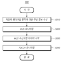
- FIG. 8 is a diagram illustrating a procedure (800) in which a terminal performs wireless communication using a low-power wake-up receiver according to one embodiment.
- the terminal can receive configuration information for a low-power wake-up operation (S810).
- a terminal may receive at least one configuration information that configures parameters used to perform a low-power wake-up operation described in the present disclosure from a base station.
- the parameters may include, for example, a monitoring period of a wake-up signal in an LR mode, monitoring occasion information, PDCCH monitoring information in an MR mode, setting information for switching between each mode, and the like.
- the configuration information for the low-power wake-up operation may include information that configures a low-power wake-up signal (LP-WUS).
- the low-power wake-up signal may be configured separately from a wake-up signal used in a conventional DRX operation.
- the configuration information for the low-power wake-up operation may include configuration information for an operation of a low-power wake-up receiver (LP-WUR; LR).
- the configuration information may be received via higher layer signaling, such as RRC signaling.
- the configuration information for the low-power wake-up operation may include configuration information for at least one timer used in the low-power wake-up operation.
- the timer may be set to a duration for monitoring a downlink control channel (PDCCH) via the MR after a wake-up signal is received via the LR.
- the timer may be set to a duration for starting or restarting after a downlink signal, i.e., a wake-up signal or a PDCCH, is received via the LR or MR, and entering the LR mode if no downlink signal is received.
- a downlink signal i.e., a wake-up signal or a PDCCH
- the terminal can monitor a wakeup signal (WUS) through a low-power wakeup receiver based on configuration information (S820).
- WUS wakeup signal
- S820 configuration information
- the terminal may switch to the LR mode based on configuration information for the low-power wake-up operation. For example, when the terminal receives an instruction to switch to the LR mode from the base station, the terminal may monitor whether a wake-up signal is transmitted from the base station through a low-power wake-up receiver corresponding to LR. Or, for another example, when a timer associated with the switch to the LR mode is configured, the terminal may switch to the LR mode according to the setting of the timer.
- the terminal When the terminal switches to the LR mode, it can monitor a wake-up signal through a low-power wake-up receiver without performing wireless communication according to MR. Based on the configuration information for the low-power wake-up operation, the terminal can perform monitoring of the wake-up signal until the wake-up signal is received.
- the terminal may perform operations related to radio resource management (RRM) related to the wake-up signal. For example, operations such as receiving and measuring a reference signal related to RRM may be performed.
- RRM radio resource management
- the terminal can start a predetermined timer when a wake-up signal is received (S830).
- the terminal can receive a wake-up signal transmitted from a base station by performing monitoring according to configuration information for a low-power wake-up operation.
- the terminal can start a LR mode transition timer.
- the LR mode transition timer can be set to a period for monitoring a downlink control channel through MR after a wake-up signal is received through LR.
- the LR mode transition timer can be set to a period for starting or restarting after a wake-up signal or a downlink control channel is received, and entering the LR mode if a downlink signal is not received.
- the timers in the two cases described above can be configured as only one timer, or can be configured together as separate timers.
- the terminal can monitor the downlink control channel through the transceiver when the timer starts (S830).
- the terminal can monitor whether a PDCCH is transmitted from the base station by turning on the transceiver corresponding to the MR while the LR mode transition timer is operating.
- the transceiver is not limited to one device, and may be composed of each device corresponding to a transmitter and a receiver.
- monitoring of a wake-up signal and monitoring of a downlink control channel can be performed simultaneously while a timer is running. That is, even if the terminal starts monitoring a PDCCH through a transceiver, it can continue monitoring the wake-up signal through a low-power wake-up receiver.
- the terminal can stop the timer and perform wireless communication through the transceiver.
- the terminal can stop the LR mode transition timer and turn off the low-power wake-up receiver. That is, when a PDCCH is received, the terminal can stop monitoring for a wake-up signal.
- the NR DRX operation can be performed by starting the DRX inactivity timer. Or, if the terminal is in the RRC Idle state, it can be switched to the connected state through paging reception. After that, data can be transmitted and received with the base station through the transceiver in the MR mode.
- the terminal may stop monitoring the downlink control channel.
- the terminal may turn off the transceiver and continue monitoring the low-power wake-up signal that was being performed. In other words, the terminal may perform operations in the LR mode.
- the terminal may stop monitoring the downlink control channel. That is, even while the LR mode transition timer is running, if a LR mode transition instruction is received from the base station, the terminal may turn off the transceiver. Accordingly, the terminal may continue to monitor the low power wake-up signal that it was performing. That is, the terminal may perform operations in the LR mode.
- the timer may be configured to restart if a wake-up signal or a downlink control channel is received while the timer is in operation.
- the LR mode transition timer may be configured to restart even if other downlink data is received in addition to the wake-up signal or the downlink control channel. If the LR mode transition timer expires without receiving any downlink data, the terminal may transition to the LR mode.
- monitoring of the wakeup signal and the downlink control channel by the terminal may be set to be continuously performed.
- the terminal may restart the LR mode transition timer and turn on the transceiver to monitor the PDCCH. Thereafter, when a wakeup signal is received while the LR mode transition timer is operating, the terminal may restart the LR mode transition timer and continuously perform monitoring of the wakeup signal and the downlink control channel.
- the terminal can transition to LR mode.
- a method and device for performing wireless communication using a low-power wake-up receiver capable of performing a wake-up operation that consumes power efficiently can be provided.
- FIG. 9 is a diagram illustrating a procedure (900) for controlling the operation of a terminal performing wireless communication using a low-power wake-up receiver by a base station according to one embodiment.
- the description given above in FIG. 8 may be omitted to avoid redundant description, and in this case, the omitted content may be substantially equally applied to the base station as long as it does not contradict the technical idea of the invention.
- the base station can transmit configuration information for low-power wake-up operation (S910).
- a base station may receive at least one configuration information that configures parameters used to perform a low-power wake-up operation described in the present disclosure to a terminal.
- the parameters may include, for example, a monitoring period of a wake-up signal in an LR mode, monitoring occasion information, PDCCH monitoring information in an MR mode, setting information for switching between each mode, and the like.
- the configuration information for the low-power wake-up operation may include information that configures a low-power wake-up signal (LP-WUS).
- the low-power wake-up signal may be configured separately from a wake-up signal used in a conventional DRX operation.
- the configuration information for the low-power wake-up operation may include configuration information for an operation of a low-power wake-up receiver (LP-WUR; LR).
- the configuration information may be transmitted via higher layer signaling, such as RRC signaling.
- Configuration information for a low-power wake-up operation may include configuration information for at least one timer used in the low-power wake-up operation.
- the base station may instruct the terminal to switch to the LR mode based on the configuration information for the low-power wake-up operation.
- the base station may transmit an instruction to switch to the LR mode to the terminal so that the terminal may monitor a wake-up signal via a low-power wake-up receiver.
- the base station may recognize that the terminal has switched to the LR mode based on the setting of the timer.
- the base station can transmit a wake-up signal to the terminal.
- the base station can transmit a downlink control channel for transmitting downlink data (S930).
- the base station can perform NR DRX operation while starting the DRX inactivity timer. Or, if the terminal is in the RRC Idle state, the base station can switch to the connected state through paging transmission. After that, data can be transmitted and received with the terminal through the transceiver in the MR mode.
- the base station when the base station transmits a wake-up signal, the base station may start a predetermined timer.
- an LR mode transition timer set individually for each terminal or set for each terminal group may be started.
- the LR mode transition timer may be set to a period during which the terminal monitors a downlink control channel via MR after receiving a wake-up signal via LR.
- the base station when it receives HARQ feedback information for transmission of downlink data, it can stop the timer and perform wireless communication with the terminal.
- the base station may retransmit the wake-up signal to the terminal. That is, if the HARQ feedback information is not received while the LR mode transition timer of the base station is operating, the LR mode transition timer expires. Accordingly, the base station may consider that the transmission of the downlink control channel and the associated downlink data to the terminal has failed, and may retransmit the wake-up signal in the LR mode.
- the base station may transmit a low power mode transition instruction to an unintended terminal among the terminal group to which the wake-up signal is transmitted. That is, if the wake-up signal is transmitted to a terminal group, the base station may individually transmit a low power mode transition instruction to a terminal that is not intended to be woken up. In this case, the base station may transmit a wake-up signal in LR mode to the corresponding terminal.
- the base station can restart the timer and perform wireless communication with the terminal.
- the LR mode transition timer is set to a period in which it starts or restarts when a downlink signal is transmitted and enters the LR mode if HARQ feedback information is not received.
- the timers in the two cases described above may be configured with only one timer, or may be configured together as separate timers.
- the base station can transmit downlink data to the terminal in MR mode, and restart the LR mode transition timer whenever HARQ feedback information for the transmitted downlink data is received. Afterwards, when the LR mode transition timer expires, a wake-up signal can be transmitted to the terminal in LR mode.
- a method and device for performing wireless communication using a low-power wake-up receiver capable of performing a wake-up operation that consumes power efficiently can be provided.
- the present disclosure proposes a specific method for an operation to be performed after waking up when a terminal that seeks to minimize power consumption by using a low-power wake-up receiver (WUR) receives a wake-up signal (WUS) through the WUR.
- WUR low-power wake-up receiver
- a long sleep duration must be used to minimize power consumption of the terminal. While a long-duration DRX operation provides a way to minimize power consumption of the terminal, it is difficult to satisfy the delay requirements for terminals requiring low latency.
- a method is required to enable the terminal to receive a wake-up signal from the base station while consuming only the minimum power even in a short-duration or Always ON state. As one solution for this, an ultra-low power receiver that can be mounted separately from a conventional transceiver has been introduced.
- an ultra-low power receiver is defined as a receiver that can receive only a wake-up signal and essential signals related thereto, and as a receiver separate from a transceiver used for conventional data transmission and reception.
- the transceiver Main Radio, MR tx./rx. module
- the transceiver used to transmit and receive the conventional NR signal/channel is turned off, and only the LP wake-up receiver is turned on to receive only the wake-up signal and essential signals related thereto, thereby drastically reducing the power consumption of the terminal.
- the terminal that receives the wake-up signal through the corresponding receiver can be instructed to switch to the main radio (MR) mode, and the terminal instructed thus can switch the mode from LR to MR and perform communication through the transceiver for the conventional NR data transmission and reception.
- LR Low power wakeup Receiver
- LP-WUR can be configured to operate Always ON or Periodically ON. Additionally, LP-WUS/WUR operation can be considered for both RRC IDLE/INACTIVE and CONNECTED modes.
- the units that can be instructed via LP-WUS can all be considered, including instructions based on UE-group, subgroup, or UE ID (UE-ID).
- a terminal operating in LP-WUR(LR) mode can be defined as a separate method from the mode in which it operates as a conventional NR transceiver.
- the WUS reception method currently under consideration in the LR mode can operate UE-specifically or UE group-specifically. If UE-specific WUS resources are allocated, a large amount of resources are required because dedicated WUS resources must be allocated to each UE. Instead of allocating a large amount of WUS resources considering resource efficiency, a UE group-based WUS allocation method can also be considered. However, if WUS resources are allocated based on UE groups and unintended UEs belong to the group, all UEs in the group must be woken up in order to wake up specific UEs belonging to the group. In this case, since the undesired UEs belonging to the group perform unnecessary wake-ups, it will be helpful in reducing power consumption if they can be quickly put back to sleep.
- a situation may occur where a terminal wakes up by judging that it has received a WUS due to a false alarm even though the base station did not transmit a wake up signal.
- the wake up of the terminal can also be defined as an undesired UE.
- the terminal monitoring WUS through LR can stop monitoring WUS through LR and start monitoring PDCCH by switching to MR.
- a base station if a base station is not aware of this, if there is data to be transmitted to the terminal, it will attempt to wake up the terminal through the WUS allocated to the LP-WUR of the terminal before transmitting downlink data to MR. If the terminal stops monitoring WUS and only performs PDCCH monitoring for MR, communication disconnection may occur due to mode mismatch between the terminal and the base station. To prepare for such a situation, the terminal will need to continue monitoring the LR mode for a certain period of time before completing the switching to MR.
- a situation may occur where a base station transmits a WUS to a terminal that is intended to be woken up, and the terminal that receives it performs PDCCH monitoring to MR, but the terminal determines that it is a false alarm WUS due to an error in receiving downlink data from the base station. This may occur when the downlink data transmission of the base station is not successfully transmitted to the terminal for some reason (e.g., a downlink synchronization (DL synch) error), and the terminal switches back to the LR mode.
- DL synch downlink synchronization
- the terminal and the base station when an unintended terminal wakes up, a method is required for the terminal and the base station to quickly determine this and for the terminal to switch back to deep sleep/LR mode.
- the terminal when the terminal switches back to LR mode due to a reception error in the terminal despite the correct wake-up of the base station, the base station may not recognize the mode switch of the terminal and may cause an RLF situation due to continuous transmission failure. It is necessary for the terminal and the base station to recognize error problems due to mode mismatch in such various situations.
- the present disclosure proposes a specific method for resolving an error situation that may occur when an unintended terminal receives a wake up signal for a terminal that monitors WUS only through LP-WUR with the MR transceiver turned off based on the aforementioned contents, and for allowing the terminal and base station to quickly recognize this and re-switch to LR/deep sleep mode (or maintain LR ON state, or synchronize low-power receiver modes between each other).
- the present disclosure proposes a method for turning ON/OFF (i.e., PDCCH monitoring) the LP-WUR and MR modules of a terminal that receives a Wake Up Signal (WUS) through a Low-Power Wake Up Receiver (LP-WUR, LR). More specifically, when the terminal receives a WUS through the LP-WUR, it is proposed to set a timer (i.e., LR_transition_timer) to define a period for continuing downlink monitoring of LR and MR while maintaining the WUR in the ON state for a specific period of time even if the tx./rx. module of the main radio for data transmission and reception is powered ON.
- LR_transition_timer i.e., LR_transition_timer
- the terminal can monitor the downlink through two receivers with both LR and MR power turned ON while the timer is running. If the terminal successfully receives a PDCCH set to be monitored by the terminal through the MR while the timer is running, the terminal terminates the timer and turns OFF the receiver of the LP-WUR. That is, the WUS monitoring through the LP WUR is stopped.
- the PDCCH set to be monitored by the terminal may include at least a PDCCH transmitting a UE-specific DCI format CRC scrambled with C-RNTI, MCS-C-RNTI, SP-CSI-RNTI, CS-RNIT(s), SL-RNTI, SL-CS-RNTI or SL Semi-Persistent Scheduling V-RNTI, which is transmitted through CSS or USS set for the terminal.
- it may include at least a PDCCH transmitting a UE-group common DCI format CRC scrambled with MCCH-RNTI, G-RNTI or G-CS-RNTI, etc., which is transmitted via CSS for MBS. If an indicator indicating a transition to LR mode is received from the base station while the timer is running or the timer expires, it is proposed that the terminal powers off the MR module and switches to LR mode to maintain WUS monitoring.
- the terminal While the timer proposed in this disclosure is operating, the terminal keeps both the Wake-Up Receiver and the Main Radio Transceiver in the ON state, and continues the downlink monitoring set in each mode. If the terminal proposed in this disclosure receives a PDCCH transmitted to itself via MR while the timer is operating, the terminal turns OFF the LR receiver of the terminal and turns ON only the MR tx./rx. module. That is, the conventional NR operation is performed. If the proposed timer expires or the base station instructs to switch to the LP-WUR mode while the proposed timer is operating, the terminal turns OFF the MR tx/rx module (i.e., stops monitoring PDCCH via the MR module) and continues WUS monitoring via only LP-WUR. If a WUS is additionally received via LP-WUR while the timer is operating, the terminal can restart the timer and continue monitoring via MR and LR while the timer is operating as described above.
- the terminal when the terminal receives a WUS through LP-WUR, the terminal turns ON the power of the tx./rx. module of the main radio for data transmission and reception and switches the WUR to the OFF state at the same time. That is, the terminal always maintains the ON state for only one of the MR and LR radio modules, and determines the radio module to be activated based on whether the WUS is received, timer expiration, LR setting information, or LR activation/deactivation instruction information. Accordingly, when the LR mode is set for any terminal, or additionally, LR mode activation is instructed, the terminal maintains the LR on and MR off states. When the terminal receives a WUS from the base station through LR, the terminal turns off the LR and turns on the MR to monitor the PDCCH.
- the terminal turns off MR and turns on LR again to switch to the LR mode.
- the terminal that receives WUS in the LR mode and switches to the MR mode monitors PDCCH through MR and operates the timer for switching to the LR mode. If the terminal successfully receives the PDCCH set to be monitored by the terminal through MR while the timer is running, the terminal can restart the timer or stop the LR switching operation based on the timer. In the latter case, the terminal can enter the LR mode again by the explicit LR mode switching setting of the base station or the LR mode activation instruction information. In the former case, the terminal can enter the LR mode when the restarted timer expires or by explicit setting/instruction information of the terminal.
- the PDCCH set to be monitored by the terminal in the above may include at least a PDCCH transmitting a UE-specific DCI format CRC scrambling such as C-RNTI, MCS-C-RNTI, SP-CSI-RNTI, CS-RNIT(s), SL-RNTI, SL-CS-RNTI or SL Semi-Persistent Scheduling V-RNTI transmitted through CSS or USS set for the terminal.
- a PDCCH transmitting a UE-group common DCI format CRC scrambling such as MCCH-RNTI, G-RNTI or G-CS-RNTI transmitted through CSS for MBS.
- the timer proposed in this disclosure is a timer that starts when a WUS is received on a WUR, and while the timer is running, the terminal performs both WUS and PDCCH monitoring through LR and MR, and provides a period for maintaining the two modes simultaneously for the duration of the timer instead of performing an immediate switch from LR to MR.
- the timer proposed in the invention can be defined as the same timer as the timer for entering the LR mode from the MR mode. That is, the timer is defined as a timer that is (re)started when a PDCCH or a WUS is received in the MR or LR. If the terminal receives an LR-related configuration message including the LR_transition_timer from the base station, the terminal in the MR mode (re)starts the LR_transition_timer whenever it receives a PDCCH. When the timer expires, the terminal enters the LR mode.
- the terminal If the terminal receives a WUS in LR mode, it starts the LR_transition_timer, and if the terminal successfully receives a PDCCH that is set to be monitored by the terminal through MR (i.e., if the terminal successfully receives a DCI format based on RNTI that is set to be monitored by the terminal as described above), it restarts the LR_transition_timer.
- the timer is stopped.
- the terminal receives a WUS in the LR mode
- the LR_transition_timer is started, and if reception of a PDCCH that the terminal is configured to monitor through MR is successful (i.e., reception of an RNTI-based DCI format that the terminal is configured to monitor as described above is successful), the LR_transition_timer is stopped to maintain the MR mode until explicit LR mode transition setting or LR mode activation indication information is received from the base station.
- the above LR_transition_timer is a new timer, and the timer value for any terminal can be set by the base station.
- the LR-transition_timer can reuse an existing timer value.
- the DRX inactivity timer for DRX operation of the terminal can be utilized as the above LR_transition_timer.
- the above LR_transition_timer is set for each terminal or terminal group in the LR mode set to monitor a certain WUS, and when the corresponding WUS is transmitted by the base station, the base station can also activate the same timer value for the LR_transition_timer set for each terminal set to monitor the corresponding WUS. Through this, the base station can detect a PDCCH transmission/reception error of a terminal that needs to switch to MR mode according to WUS transmission according to the operation embodiment of the terminal according to WUS reception defined above, or synchronize terminals that have switched to MR mode according to WUS transmission and have switched back to LR mode according to timer expiration among the terminals.
- the proposed timer can also be applied to PDCCH transmission/reception errors on MR after WUS transmission/reception between the base station and the terminal. That is, this means that the proposed timer can operate not only at the terminal but also at the base station. Even if the transmission of the WUS was a correct transmission to the desired UE, if the base station does not receive any feedback (e.g., HARQ feedback for PDCCH) from the terminal during the proposed timer, it may correspond to the case where the terminal did not wake up for some reason, or woke up but did not receive PDCCH on MR. At this time, the terminal may have entered the LR mode again or may not have switched to the MR mode.
- any feedback e.g., HARQ feedback for PDCCH
- the base station may start the proposed timer when it transmits a WUS to the terminal, and may reattempt the WUS transmission to the LR receiver of the terminal when the timer expires. If, while the timer is running, any UL signal (e.g., HARQ feedback for DL data) is received from the terminal, the timer stops and the terminal's MR mode transition is recognized.
- any UL signal e.g., HARQ feedback for DL data
- a (maximum) time interval is defined between the time point at which the base station transmits a WUS on LR and the time point at which the PDCCH corresponding to the transmitted WUS is transmitted on MR, it is preferable that the value of the timer proposed in the present disclosure be set to a value greater than the time interval.
- an LR_transition_timer value for maintaining an MR activation state according to WUS reception and a timer-based LR mode transition according to the period may be set from the base station.
- the LR_transition_timer value may be set through a separate RRC parameter for the terminal set for LR-WUS monitoring, or may follow the DRX inactivity timer value as described above.
- the terminal activates MR to perform monitoring for PDCCH based on the RNTI set to be monitored by the terminal.
- the LR_transition_timer is operated while maintaining the dual activation mode state that maintains the activation state for LR, and if PDCCH reception is successful via MR before the timer expires, the timer can be spotted and switched to a complete MR state (i.e., switched LR to off state).
- the above LR_transition_timer allows the base station or the network to manage the timer value according to the setting value of each terminal, and when the LR_transition_timer is activated for any terminal, the base station or the network can operate the timer in synchronization with the timer count of the terminal based on the LR-transition_timer value set for the terminal. Accordingly, the base station or the network can synchronize the expiration and reset/restart of the LR-transition_timer for any terminal and synchronize whether or not to switch the LR mode accordingly.
- Case 1 After receiving WUS, if PDCCH and/or PDSCH corresponding thereto set to be monitored by the terminal through MR is received (however, if both MR and LR are kept ON when receiving the above WUS) (case 1-1, 1-2)
- Case 1 describes two examples: a case where the timer is operated only in the terminal (case 1-1) and a case where the timer is operated together in both the base station and the terminal (case 1-2).
- Fig. 10 is a diagram for explaining a low-power wake-up operation using a timer of a terminal according to one embodiment. Referring to Fig. 10, the operations of the terminal and base station in case 1-1 are as follows.
- LR_transition_timer Duration to monitor PDCCH that can be transmitted to MR after receiving WUS via LR.
- the terminal continues to monitor downlink through both LR and MR while LR_transition_timer is running.
- NR DRX operation can be performed by starting the DRX inactivity timer.
- the state can be switched to connected by receiving paging.
- LP-WUR/WUS related configuration information including at least the following information:
- LR_transition_timer Duration to monitor PDCCH that can be transmitted to MR after receiving WUS via LR.
- the transition is recognized either through an LP-WUR/LP-WUS activation transmission or by a specific timer.
- NR DRX operation can be performed by starting the DRX inactivity timer.
- the state can be switched to connected through paging transmission.
- Fig. 11 is a diagram for explaining a low-power wake-up operation using a timer of a terminal and a base station according to one embodiment. Referring to Fig. 11, the operations of the terminal and the base station in case 1-2 are as follows.
- LP-WUR/WUS related configuration information including at least the following information:
- LR_transition_timer Duration to monitor PDCCH that can be transmitted to MR after receiving WUS via LR.
- the transition is recognized either through an LP-WUR/LP-WUS activation transmission or by a specific timer.
- a WUS is transmitted to wake up the terminal.
- the LR_transition_timer set individually for each terminal set to monitor the WUS or set for each terminal group is started.
- the LR_transition_timer While the LR_transition_timer is running, if HARQ feedback for the transmitted DL data is received, the LR_transition_timer is stopped and communication is performed through the NR signal/channel.
- NR DRX operation can be performed by starting the DRX inactivity timer.
- the state can be switched to connected through paging transmission.
- Case 2 describes two examples: a case where the timer is operated only in the terminal, and a case where the timer is operated together in both the base station and the terminal.
- FIG. 12 is a diagram for explaining a low-power wake-up operation when a timer of a terminal expires according to one embodiment. Referring to FIG. 12, the operations of the terminal and the base station in case 2-1 are as follows.
- LR_transition_timer Duration to monitor PDCCH that can be transmitted to MR after receiving WUS via LR.
- Switching is done by LP-WUR/LP-WUS activation instruction from base station, or by a specific timer.
- the terminal continues to monitor downlink through both LR and MR while LR_transition_timer is running.
- the MR transceiver can be turned OFF.
- It may include WUS monitoring via LR receiver and WUS related RRM operations.
- LP-WUR/WUS related configuration information including at least the following information:
- LR_transition_timer Duration to monitor PDCCH that can be transmitted to MR after receiving WUS via LR.
- the transition is recognized either through an LP-WUR/LP-WUS activation transmission or by a specific timer.
- FIG. 13 is a diagram for explaining a low-power wake-up operation when the timer of a terminal and a base station expires according to one embodiment. Referring to FIG. 13, the operations of the terminal and the base station in case 2-2 are as follows.
- LP-WUR/WUS related configuration information including at least the following information:
- LR_transition_timer Duration to monitor PDCCH that can be transmitted to MR after receiving WUS via LR.
- the transition is recognized either through an LP-WUR/LP-WUS activation transmission or by a specific timer.
- FIG. 14 is a diagram for explaining a low-power wake-up operation according to an LR mode switching instruction according to one embodiment. Referring to FIG. 14, the operations of the terminal and base station in case 3 are as follows.
- LR_transition_timer Duration to monitor PDCCH that can be transmitted to MR after receiving WUS via LR.
- Switching is done by LP-WUR/LP-WUS activation instruction from base station, or by a specific timer.
- the terminal continues to monitor downlink through both LR and MR while LR_transition_timer is running.
- It may include WUS monitoring via LR receiver and WUS related RRM operations.
- LP-WUR/WUS related configuration information including at least the following information:
- LR_transition_timer Duration to monitor PDCCH that can be transmitted to MR after receiving WUS via LR.
- the transition is recognized either through an LP-WUR/LP-WUS activation transmission or by a specific timer.
- the base station transmits UE-group based WUS.
- the base station transmits an indicator to enter LR mode so that the UE can enter LR mode immediately.
- FIG. 15 is a diagram for explaining a low-power wake-up operation when a timer according to one embodiment is set as a timer for entering LR mode.
- the operations of the terminal and base station in case 4 are as follows.
- LR_transition_timer A timer that is (re)started when a downlink signal is received in LR or MR. If no downlink signal is received (expires) while the timer is running, the device enters LR mode.
- Switching is done by LP-WUR/LP-WUS activation instruction from base station, or by LR_transition_timer expiry.
- the terminal continues to monitor downlink through both LR and MR while LR_transition_timer is running.
- LP-WUR/WUS related configuration information including at least the following information:
- LR_transition_timer A timer that is (re)started when a downlink signal is transmitted in LR or MR. If no uplink feedback for any downlink signal is received (expires) while the timer is running, the terminal is recognized as having entered LR mode.
- Transitions are recognized either by LP-WUR/LP-WUS activation transmission or by LR_transition_timer expiry.
- Communication is performed via NR signal/channel while operating LR_transition_timer.
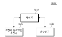
- Fig. 16 is a drawing showing the configuration of a terminal (1600) according to another embodiment.
- a terminal (1600) includes a low-power wake-up receiver (1620), a transceiver (1630), and a controller (1610) that controls the operation of the low-power wake-up receiver and the transceiver.
- the controller (1610) controls the overall operation of the terminal (1600) according to the method of performing wireless communication using a low-power wake-up receiver necessary for performing the present invention described above.
- the controller (1610) can receive configuration information for low power wake-up operations.
- the controller (1610) may receive at least one configuration information that configures parameters used to perform the low-power wake-up operation described in the present disclosure from the base station.
- the configuration information may be received via higher layer signaling, such as RRC signaling.
- the configuration information for the low-power wake-up operation may include configuration information for at least one timer used in the low-power wake-up operation.
- the timer may be set to a duration for monitoring a downlink control channel (PDCCH) via the MR after a wake-up signal is received via the LR.
- the timer may be set to a duration for starting or restarting after a downlink signal, i.e., a wake-up signal or a PDCCH, is received via the LR or MR, and entering the LR mode if no downlink signal is received.
- a downlink signal i.e., a wake-up signal or a PDCCH
- the controller (1610) may monitor a wakeup signal (WUS) through a low-power wakeup receiver based on configuration information.
- the controller (1610) may switch to the LR mode based on the configuration information for the low-power wakeup operation.
- the controller (1610) may monitor whether a wakeup signal is transmitted from the base station through the low-power wakeup receiver corresponding to LR.
- the controller (1610) may switch to the LR mode according to the setting of the corresponding timer.
- the controller (1610) when switched to the LR mode, may monitor a wake-up signal through the low-power wake-up receiver (1620) without performing wireless communication according to MR. Based on the configuration information for the low-power wake-up operation, the controller (1610) may perform monitoring of the wake-up signal until the wake-up signal is received.
- the controller (1610) may perform operations related to radio resource management (RRM) related to the wake-up signal. For example, operations such as receiving and measuring a reference signal related to RRM may be performed.
- RRM radio resource management
- the controller (1610) may start a predetermined timer when a wake-up signal is received.
- the controller (1610) may perform monitoring according to configuration information for a low-power wake-up operation to receive a wake-up signal transmitted from a base station.
- the controller (1610) may start a LR mode transition timer when a wake-up signal is received.
- the LR mode transition timer may be set to a period for monitoring a downlink control channel through MR after a wake-up signal is received through LR.
- the LR mode transition timer may be set to a period for starting or restarting after a wake-up signal or a downlink control channel is received, and entering the LR mode if a downlink signal is not received.
- the timers in the two cases described above may be configured as either one of the timers or may be configured together as separate timers.
- the controller (1610) can monitor the downlink control channel through the transceiver when the timer starts.
- the controller (1610) can turn on the transceiver (1630) corresponding to the MR while the LR mode switching timer is operating to monitor whether the PDCCH is transmitted from the base station.
- the transceiver is not limited to one device, and may be configured with each device corresponding to a transmitter and a receiver.
- monitoring of a wake-up signal and monitoring of a downlink control channel can be performed simultaneously while a timer is running. That is, even if the controller (1610) starts monitoring a PDCCH through a transceiver, it can continue monitoring the wake-up signal through a low-power wake-up receiver.
- the controller (1610) can stop a timer and perform wireless communication through a transceiver when a downlink control channel is received.
- the controller (1610) can stop the LR mode transition timer and turn off the low-power wake-up receiver. That is, when a PDCCH is received, the controller (1610) can stop monitoring for a wake-up signal.
- the NR DRX operation can be performed by starting the DRX inactivity timer. Or, if the terminal is in the RRC Idle state, it can be switched to the connected state through paging reception. After that, data can be transmitted and received with the base station through the transceiver in the MR mode.
- the controller (1610) may stop monitoring the downlink control channel.
- the terminal may turn off the transceiver and continue monitoring the low-power wake-up signal that was being performed. That is, the controller (1610) may perform an operation in the LR mode.
- the controller (1610) may stop monitoring the downlink control channel. That is, even while the LR mode transition timer is running, if a transition instruction to the LR mode is received from the base station, the controller (1610) may turn off the transceiver. Accordingly, the controller (1610) may continue to monitor the low power wake-up signal that it was performing. That is, the controller (1610) may perform an operation in the LR mode.
- the timer may be configured to restart if a wake-up signal or a downlink control channel is received while the timer is in operation.
- the LR mode transition timer may be configured to restart even if other downlink data is received in addition to the wake-up signal or the downlink control channel. If the LR mode transition timer expires without receiving any downlink data, the controller (1610) may transition to the LR mode.
- monitoring of the wake-up signal and the downlink control channel by the terminal may be set to be continuously performed.
- the controller (1610) may restart the LR mode transition timer and turn on the transceiver to monitor the PDCCH. Thereafter, when a wake-up signal is received while the LR mode transition timer is operating, the controller (1610) may restart the LR mode transition timer and continuously perform monitoring of the wake-up signal and the downlink control channel.
- monitoring of a wake-up signal by the terminal may be set to be stopped. That is, when monitoring of a wake-up signal and a downlink control channel is performed simultaneously, when a downlink control channel is received, the controller (1610) may restart the LR mode transition timer. In this case, the controller (1610) may turn off the low-power wake-up receiver and operate in the MR mode. In addition, the controller (1610) may transmit a HARQ feedback message for downlink data to the base station.
- the controller (1610) can transition to the LR mode.
- a method and device for performing wireless communication using a low-power wake-up receiver capable of performing a wake-up operation that consumes power efficiently can be provided.
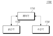
- Fig. 17 is a diagram showing the configuration of a base station (1700) according to another embodiment.
- a base station (1700) includes a transmitter (1720), a receiver (1730), and a controller (1710) that controls the operation of the transmitter and the receiver.
- the controller (1710) controls the overall operation of the base station (1700) according to the method of performing wireless communication using the low-power wake-up receiver required to perform the above-described present invention.
- the transmitter (1720) transmits downlink control information, data, and messages to the terminal through the corresponding channel.
- the receiver (1730) receives uplink control information, data, and messages from the terminal through the corresponding channel.
- the controller (1710) can transmit configuration information for a low-power wake-up operation.
- the controller (1710) can receive at least one configuration information that configures parameters used to perform the low-power wake-up operation described in the present disclosure to the terminal.
- the configuration information can be transmitted via upper layer signaling, such as RRC signaling.
- Configuration information for a low-power wake-up operation may include configuration information for at least one timer used in the low-power wake-up operation.
- the controller (1710) may transmit a wakeup signal (WUS) to the terminal based on the configuration information when downlink data to be transmitted to the terminal is confirmed.
- the controller (1710) may instruct the terminal to switch to the LR mode based on the configuration information for the low-power wakeup operation.
- the controller (1710) may transmit an instruction to switch to the LR mode to the terminal so that the terminal monitors the wakeup signal through a low-power wakeup receiver.
- the controller (1710) may recognize that the terminal has switched to the LR mode based on the setting of the corresponding timer.
- the controller (1710) may transmit a wake-up signal to the terminal if it is necessary to transmit downlink data to the terminal after the terminal has switched to LR mode.
- the controller (1710) can transmit a downlink control channel for transmitting downlink data. If the terminal is in an RRC Connected state, the controller (1710) can perform an NR DRX operation while starting a DRX inactivity timer. Or, if the terminal is in an RRC Idle state, the controller (1710) can switch to a connected state through paging transmission. Thereafter, data can be transmitted and received with the terminal through a transceiver in the MR mode.
- the controller (1710) when it transmits a wake-up signal, it may start a predetermined timer.
- an LR mode transition timer set individually for each terminal or set for each terminal group may be started.
- the LR mode transition timer may be set to a period during which the terminal monitors a downlink control channel via MR after receiving a wake-up signal via LR.
- the controller (1710) can stop the timer and perform wireless communication with the terminal.
- the controller (1710) may retransmit the wake-up signal to the terminal. That is, if the HARQ feedback information is not received while the LR mode transition timer of the base station is operating, the LR mode transition timer expires. Accordingly, the controller (1710) may report that the transmission of the downlink control channel and associated downlink data to the terminal has failed, and may retransmit the wake-up signal in the LR mode.
- the controller (1710) may transmit a low power mode transition instruction to an unintended terminal among the terminal groups to which the wake-up signal is transmitted. That is, if the wake-up signal is transmitted to a terminal group, the controller (1710) may individually transmit a low power mode transition instruction to a terminal that is not intended to be woken up. In this case, the controller (1710) may transmit a wake-up signal in LR mode to the corresponding terminal.
- the controller (1710) can restart the timer and perform wireless communication with the terminal.
- the LR mode transition timer is set to a period for starting or restarting when a downlink signal is transmitted and entering the LR mode if HARQ feedback information is not received.
- the timers in the two cases described above may be configured with only one timer, or may be configured together as separate timers.
- the controller (1710) may transmit downlink data to the terminal in MR mode, and restart the LR mode transition timer whenever HARQ feedback information for the transmitted downlink data is received. Thereafter, when the LR mode transition timer expires, the controller (1710) may transmit a wake-up signal to the terminal in LR mode.
- a method and device for performing wireless communication using a low-power wake-up receiver capable of performing a wake-up operation that consumes power efficiently can be provided.
- the above-described embodiments can be implemented through various means.
- the embodiments can be implemented by hardware, firmware, software, or a combination thereof.
- the method according to the present embodiments can be implemented by one or more ASICs (Application Specific Integrated Circuits), DSPs (Digital Signal Processors), DSPDs (Digital Signal Processing Devices), PLDs (Programmable Logic Devices), FPGAs (Field Programmable Gate Arrays), processors, controllers, microcontrollers, or microprocessors.
- ASICs Application Specific Integrated Circuits
- DSPs Digital Signal Processors
- DSPDs Digital Signal Processing Devices
- PLDs Programmable Logic Devices
- FPGAs Field Programmable Gate Arrays
- processors controllers, microcontrollers, or microprocessors.
- the method according to the present embodiments may be implemented in the form of a device, procedure, or function that performs the functions or operations described above.
- the software code may be stored in a memory unit and may be driven by a processor.
- the memory unit may be located inside or outside the processor and may exchange data with the processor by various means already known.
- system may generally refer to a computer-related entity hardware, a combination of hardware and software, software, or software in execution.
- the aforementioned components may be, but are not limited to, a process driven by a processor, a processor, a controller, a control processor, an object, a thread of execution, a program, and/or a computer.
- an application running on a controller or a processor and the controller or the processor can both be components.
- One or more components may be within a process and/or thread of execution, and the components may be located on a single device (e.g., a system, a computing device, etc.) or distributed across two or more devices.
Landscapes
- Mobile Radio Communication Systems (AREA)
Abstract
본 실시예들은 저전력 웨이크업 수신기(low power wakeup receiver; LR)를 이용하여 단말이 무선 통신을 수행하는 방법에 있어서, 저전력 웨이크업 동작에 대한 구성 정보를 수신하는 단계, 구성 정보에 기초하여, 저전력 웨이크업 수신기를 통하여, 웨이크업 신호(wakeup signal; WUS)를 모니터링하는 단계, 웨이크업 신호가 수신되는 경우, 소정의 타이머를 시작하는 단계 및 타이머의 시작 시, 송수신기를 통하여, 하향링크 제어 채널을 모니터링하는 단계를 포함하는 방법을 제공한다.
Description
본 실시예들은 차세대 무선 액세스 망(본 개시에서, "5G", "NR[New Radio]", "5G-Advanced", "6G" 또는 이후의 3GPP 무선 액세스 망을 의미함)에서 저전력 웨이크업 수신기를 이용하여 무선 통신을 수행하는 방법 및 장치에 대해서 제안한다.
3GPP는 무선통신 기술에 대한 연구 개발을 지속하고 있다. 무선 통신 시스템에서는 지연 시간, 안정성, 가용성 외에도 단말의 에너지 효율성도 매우 중요한 고려 대상이다. 현재 단말은 개인의 사용 시간에 따라 자주 충전을 해야 할 수 있다. 단말의 배터리 수명 연장에 대한 설계는 에너지 효율성을 향상하고 더 나은 사용자 경험을 위해 필수적이다. 지속적인 에너지원이 없는 단말의 경우 에너지 효율성이 중요하다.
전력 소비는 구성된 웨이크업 기간 길이에 따라 달라질 수 있다. 다만, 배터리의 수명 요구 사항을 충족하기 위해 큰 값을 갖는 DRX 사이클이 사용되는 경우 등에는 결과적으로 높은 지연 시간이 발생하므로, 긴 배터리 수명과 낮은 지연 시간을 모두 요구하는 서비스에는 적합하지 않을 수 있다.
이러한 측면의 일환으로, 단말이 웨이크업 동작을 수행하는데 있어 보다 효율적으로 전력을 소비할 수 있도록 하는 방법에 대한 구체적인 설계가 필요하게 된다.
본 개시의 실시예들은, 저전력 웨이크업 수신기를 이용하여 무선 통신을 수행하는 방법 및 장치를 제공할 수 있다.
일 측면에서, 본 실시예들은 저전력 웨이크업 수신기(low power wakeup receiver; LR)를 이용하여 단말이 무선 통신을 수행하는 방법에 있어서, 저전력 웨이크업 동작에 대한 구성 정보를 수신하는 단계, 구성 정보에 기초하여, 저전력 웨이크업 수신기를 통하여, 웨이크업 신호(wakeup signal; WUS)를 모니터링하는 단계, 웨이크업 신호가 수신되는 경우, 소정의 타이머를 시작하는 단계 및 타이머의 시작 시, 송수신기를 통하여, 하향링크 제어 채널을 모니터링하는 단계를 포함하는 방법을 제공할 수 있다.
다른 측면에서, 본 실시예들은 기지국이 저전력 웨이크업 수신기를 이용하여 무선 통신을 수행하는 단말의 동작을 제어하는 방법에 있어서, 저전력 웨이크업 동작에 대한 구성 정보를 전송하는 단계, 단말로 전송될 하향링크 데이터가 확인되는 경우, 구성 정보에 기초하여, 웨이크업 신호(wakeup signal; WUS)를 단말로 전송하는 단계 및 하향링크 데이터의 전송을 위한 하향링크 제어 채널을 전송하는 단계를 포함하는 방법을 제공할 수 있다.
또 다른 측면에서, 본 실시예들은 저전력 웨이크업 수신기(low power wakeup receiver; LR)를 이용하여 무선 통신을 수행하는 단말에 있어서, 저전력 웨이크업 수신기, 송수신기 및 저전력 웨이크업 수신기와 송수신기의 동작을 제어하는 제어기를 포함하되, 제어기는, 저전력 웨이크업 동작에 대한 구성 정보를 수신하고, 구성 정보에 기초하여, 저전력 웨이크업 수신기를 통하여, 웨이크업 신호(wakeup signal; WUS)를 모니터링하고, 웨이크업 신호가 수신되는 경우, 소정의 타이머를 시작하고, 타이머의 시작 시, 송수신기를 통하여, 하향링크 제어 채널을 모니터링하는 단말을 제공할 수 있다.
또 다른 측면에서, 본 실시예들은 저전력 웨이크업 수신기를 이용하여 무선 통신을 수행하는 단말의 동작을 제어하는 기지국에 있어서, 송신기, 수신기 및 송신기와 수신기의 동작을 제어하는 제어기를 포함하되, 제어기는, 저전력 웨이크업 동작에 대한 구성 정보를 전송하고, 단말로 전송될 하향링크 데이터가 확인되는 경우, 구성 정보에 기초하여, 웨이크업 신호(wakeup signal; WUS)를 단말로 전송하고, 하향링크 데이터의 전송을 위한 하향링크 제어 채널을 전송하는 기지국을 제공할 수 있다.
본 실시예들에 의하면, 효율적으로 전력을 소비하는 웨이크업 동작을 수행할 수 있는 저전력 웨이크업 수신기를 이용하여 무선 통신을 수행하는 방법 및 장치를 제공할 수 있다.
또한, 전력 소비를 최소화하고자 하는 단말이 NR과 같은 메인 라디오(main radio; MR) 송수신기(transceiver)와 별개의 초 저전력 수신기만을 이용하여 하향링크 신호를 모니터링하는 경우, 기지국으로부터 의도하지 않은 WUS 수신으로 인해 깨어난 단말이 이를 인식하고 MR 트랜시버로의 모니터링을 빠르게 종료하게 함으로써, 단말의 전력 소비를 최소화하게 할 수 있다.
또한, 단말과 기지국 사이에 발생할 수 있는 수신기 모드 미스매치(mismatch) 상황을 단말 및 기지국이 빠르게 인지하도록 함으로써, 단말 및 기지국의 통신 단절 문제를 해결할 수 있다.
도 1은 본 실시예가 적용될 수 있는 NR 무선 통신 시스템에 대한 구조를 간략하게 도시한 도면이다.
도 2는 본 실시예가 적용될 수 있는 NR 시스템에서의 프레임 구조를 설명하기 위한 도면이다.
도 3은 본 실시예가 적용될 수 있는 무선 접속 기술이 지원하는 자원 그리드를 설명하기 위한 도면이다.
도 4는 본 실시예가 적용될 수 있는 무선 접속 기술이 지원하는 대역폭 파트를 설명하기 위한 도면이다.
도 5는 본 실시예가 적용될 수 있는 무선 접속 기술에서의 동기 신호 블록을 예시적으로 도시한 도면이다.
도 6는 본 실시예가 적용될 수 있는 무선 접속 기술에서의 랜덤 액세스 절차를 설명하기 위한 도면이다.
도 7은 CORESET에 대해서 설명하기 위한 도면이다.
도 8은 일 실시예에 따른 단말이 저전력 웨이크업 수신기를 이용하여 무선 통신을 수행하는 절차를 도시한 도면이다.
도 9는 일 실시예에 따른 기지국이 저전력 웨이크업 수신기를 이용하여 무선 통신을 수행하는 단말의 동작을 제어하는 절차를 도시한 도면이다.
도 10은 일 실시예에 따른 단말의 타이머를 이용한 저전력 웨이크업 동작을 설명하기 위한 도면이다.
도 11은 일 실시예에 따른 단말과 기지국의 타이머를 이용한 저전력 웨이크업 동작을 설명하기 위한 도면이다.
도 12는 일 실시예에 따른 단말의 타이머가 만료된 경우 저전력 웨이크업 동작을 설명하기 위한 도면이다.
도 13은 일 실시예에 따른 단말과 기지국의 타이머가 만료된 경우 저전력 웨이크업 동작을 설명하기 위한 도면이다.
도 14는 일 실시예에 따른 LR 모드 전환 지시에 따른 저전력 웨이크업 동작을 설명하기 위한 도면이다.
도 15는 일 실시예에 따른 타이머가 LR 모드 진입을 위한 타이머로 설정된 경우 저전력 웨이크업 동작을 설명하기 위한 도면이다.
도 16은 또 다른 실시예에 의한 단말의 구성을 보여주는 도면이다.
도 17은 또 다른 실시예에 의한 기지국의 구성을 보여주는 도면이다.
이하, 본 개시의 일부 실시예들을 예시적인 도면을 참조하여 상세하게 설명한다. 각 도면의 구성 요소들에 참조부호를 부가함에 있어서, 동일한 구성 요소들에 대해서는 비록 다른 도면상에 표시되더라도 가능한 한 동일한 부호를 가질 수 있다. 또한, 본 실시예들을 설명함에 있어, 관련된 공지 구성 또는 기능에 대한 구체적인 설명이 본 기술 사상의 요지를 흐릴 수 있다고 판단되는 경우에는 그 상세한 설명은 생략할 수 있다. 본 명세서 상에서 언급된 "포함한다", "갖는다", "이루어진다" 등이 사용되는 경우 "~만"이 사용되지 않는 이상 다른 부분이 추가될 수 있다. 구성 요소를 단수로 표현한 경우에 특별한 명시적인 기재 사항이 없는 한 복수를 포함하는 경우를 포함할 수 있다.
또한, 본 개시의 구성 요소를 설명하는 데 있어서, 제1, 제2, A, B, (a), (b) 등의 용어를 사용할 수 있다. 이러한 용어는 그 구성 요소를 다른 구성 요소와 구별하기 위한 것일 뿐, 그 용어에 의해 해당 구성 요소의 본질, 차례, 순서 또는 개수 등이 한정되지 않는다.
구성 요소들의 위치 관계에 대한 설명에 있어서, 둘 이상의 구성 요소가 "연결", "결합" 또는 "접속" 등이 된다고 기재된 경우, 둘 이상의 구성 요소가 직접적으로 "연결", "결합" 또는 "접속"될 수 있지만, 둘 이상의 구성 요소와 다른 구성 요소가 더 "개재"되어 "연결", "결합" 또는 "접속"될 수도 있다고 이해되어야 할 것이다. 여기서, 다른 구성 요소는 서로 "연결", "결합" 또는 "접속"되는 둘 이상의 구성 요소 중 하나 이상에 포함될 수도 있다.
구성 요소들이나, 동작 방법이나 제작 방법 등과 관련한 시간적 흐름 관계에 대한 설명에 있어서, 예를 들어, "~후에", "~에 이어서", "~다음에", "~전에" 등으로 시간적 선후 관계 또는 흐름적 선후 관계가 설명되는 경우, "바로" 또는 "직접"이 사용되지 않는 이상 연속적이지 않은 경우도 포함할 수 있다.
한편, 구성 요소에 대한 수치 또는 그 대응 정보(예: 레벨 등)가 언급된 경우, 별도의 명시적 기재가 없더라도, 수치 또는 그 대응 정보는 각종 요인(예: 공정상의 요인, 내부 또는 외부 충격, 노이즈 등)에 의해 발생할 수 있는 오차 범위를 포함하는 것으로 해석될 수 있다.
본 명세서에서의 무선 통신 시스템은 음성, 데이터 패킷 등과 같은 다양한 통신 서비스를 무선자원을 이용하여 제공하기 위한 시스템을 의미하며, 단말과 기지국 또는 코어 네트워크 등을 포함할 수 있다.
이하에서 개시하는 본 실시예들은 다양한 무선 접속 기술을 사용하는 무선 통신 시스템에 적용될 수 있다. 예를 들어, 본 실시예들은 CDMA(code division multiple access), FDMA(frequency division multiple access), TDMA(timedivision multiple access), OFDMA(orthogonal frequency division multiple access), SC-FDMA(singlecarrier frequency division multiple access) 또는 NOMA(non-orthogonal multiple access) 등과 같은 다양한 무선 접속 기술에 적용될 수 있다. 또한, 무선 접속 기술은 특정 접속 기술을 의미하는 것뿐만 아니라 3GPP, 3GPP2, WiFi, Bluetooth, IEEE, ITU 등 다양한 통신 협의기구에서 제정하는 각 세대별 통신 기술을 의미할 수 있다. 예를 들어, CDMA는 UTRA(universal terrestrial radio access)나 CDMA2000과 같은 무선 기술로 구현될 수 있다. TDMA는 GSM(global system for mobile communications)/GPRS(general packet radio service)/EDGE(enhanced datarates for GSM evolution)와 같은 무선 기술로 구현될 수 있다. OFDMA는 IEEE(institute of electrical andelectronics engineers) 802.11(Wi-Fi), IEEE 802.16(WiMAX), IEEE 802-20, E-UTRA(evolved UTRA) 등과 같은 무선 기술로 구현될 수 있다. IEEE 802.16m은 IEEE 802.16e의 진화로, IEEE 802.16e에 기반한 시스템과의 하위 호환성(backward compatibility)를 제공한다. UTRA는 UMTS(universal mobile telecommunications system)의 일부이다. 3GPP(3rd generation partnership project) LTE(long term evolution)은 E-UTRA(evolved-UMTSterrestrial radio access)를 사용하는 E-UMTS(evolved UMTS)의 일부로써, 하향링크에서 OFDMA를 채용하고 상향링크에서 SC-FDMA를 채용한다. 이와 같이 본 실시예들은 현재 개시되거나 상용화된 무선 접속 기술에 적용될 수 있고, 현재 개발 중이거나 향후 개발될 무선 접속 기술에 적용될 수도 있다.
한편, 본 명세서에서의 단말은 무선 통신 시스템에서 기지국과 통신을 수행하는 무선 통신 모듈을 포함하는 장치를 의미하는 포괄적 개념으로서, WCDMA, LTE, NR, HSPA 및 IMT-2020(5G 또는 New Radio) 등에서의 UE(User Equipment)는 물론, GSM에서의 MS(Mobile Station), UT(User Terminal), SS(Subscriber Station), 무선 기기(wireless device) 등을 모두 포함하는 개념으로 해석되어야 할 것이다. 또한, 단말은 사용 형태에 따라 스마트 폰과 같은 사용자 휴대 기기가 될 수도 있고, V2X 통신 시스템에서는 차량, 차량 내의 무선 통신 모듈을 포함하는 장치 등을 의미할 수도 있다. 또한, 기계 형태 통신(Machine Type Communication) 시스템의 경우에 기계 형태 통신이 수행되도록 통신 모듈을 탑재한 MTC 단말, M2M 단말, URLLC 단말 등을 의미할 수도 있다.
본 명세서의 기지국 또는 셀은 네트워크 측면에서 단말과 통신하는 종단을 지칭하며, 노드-B(Node-B), eNB(evolved Node-B), gNB(gNode-B), LPN(Low Power Node), 섹터(Sector), 싸이트(Site), 다양한 형태의 안테나, BTS(Base Transceiver System), 액세스 포인트(Access Point), 포인트(예를 들어, 송신포인트, 수신포인트, 송수신포인트), 릴레이 노드(Relay Node), 메가 셀, 매크로 셀, 마이크로 셀, 피코 셀, 펨토 셀, RRH(Remote Radio Head), RU(Radio Unit), 스몰 셀(small cell) 등 다양한 커버리지 영역을 모두 포괄하는 의미이다. 또한, 셀은 주파수 도메인에서의 BWP(Bandwidth Part)를 포함하는 의미일 수 있다. 예를 들어, 서빙 셀은 단말의 Activation BWP를 의미할 수 있다.
앞서 나열된 다양한 셀은 하나 이상의 셀을 제어하는 기지국이 존재하므로 기지국은 두 가지 의미로 해석될 수 있다. 1) 무선 영역과 관련하여 메가 셀, 매크로 셀, 마이크로 셀, 피코 셀, 펨토 셀, 스몰 셀(small cell)을 제공하는 장치 그 자체이거나, 2) 무선 영역 그 자체를 지시할 수 있다. 1)에서 소정의 무선 영역을 제공하는 장치들이 동일한 개체에 의해 제어되거나 무선 영역을 협업으로 구성하도록 상호 작용하는 모든 장치들을 모두 기지국으로 지시한다. 무선 영역의 구성 방식에 따라 포인트, 송수신 포인트, 송신 포인트, 수신 포인트 등은 기지국의 일 실시 예가 된다. 2)에서 사용자 단말의 관점 또는 이웃하는 기지국의 입장에서 신호를 수신하거나 송신하게 되는 무선 영역 그 자체를 기지국으로 지시할 수도 있다.
본 명세서에서 셀(Cell)은 송수신 포인트로부터 전송되는 신호의 커버리지 또는 송수신 포인트(transmission point 또는 transmission/reception point)로부터 전송되는 신호의 커버리지를 가지는 요소 반송파(component carrier), 그 송수신 포인트 자체를 의미할 수 있다.
상향링크(Uplink, UL, 또는 업링크)는 단말에 의해 기지국으로 데이터를 송수신하는 방식을 의미하며, 하향링크(Downlink, DL, 또는 다운링크)는 기지국에 의해 단말로 데이터를 송수신하는 방식을 의미한다. 하향링크(downlink)는 다중 송수신 포인트에서 단말로의 통신 또는 통신 경로를 의미할 수 있으며, 상향링크(uplink)는 단말에서 다중 송수신 포인트로의 통신 또는 통신 경로를 의미할 수 있다. 이때, 하향링크에서 송신기는 다중 송수신 포인트의 일부분일 수 있고, 수신기는 단말의 일부분일 수 있다. 또한, 상향링크에서 송신기는 단말의 일부분일 수 있고, 수신기는 다중 송수신 포인트의 일부분일 수 있다.
상향링크와 하향링크는, PDCCH(Physical Downlink Control CHannel), PUCCH(Physical Uplink Control CHannel) 등과 같은 제어 채널을 통하여 제어 정보를 송수신하고, PDSCH(Physical Downlink Shared CHannel), PUSCH(Physical Uplink Shared CHannel) 등과 같은 데이터 채널을 구성하여 데이터를 송수신한다. 이하에서는 PUCCH, PUSCH, PDCCH 및 PDSCH 등과 같은 채널을 통해 신호가 송수신되는 상황을 'PUCCH, PUSCH, PDCCH 및 PDSCH를 전송, 수신한다'는 형태로 표기하기도 한다.
설명을 명확하게 하기 위해, 이하에서는 본 기술 사상을 3GPP LTE/LTE-A/NR(New RAT) 통신 시스템을 위주로 기술하지만 본 기술적 특징이 해당 통신 시스템에 제한되는 것은 아니다.
3GPP에서는 4G(4th-Generation) 통신 기술에 대한 연구 이후에 ITU-R의 차세대 무선 접속 기술의 요구사항에 맞추기 위한 5G(5th-Generation)통신 기술을 개발한다. 구체적으로, 3GPP는 5G 통신 기술로 LTE-Advanced 기술을 ITU-R의 요구사항에 맞추어 향상시킨 LTE-A pro와 4G 통신 기술과는 별개의 새로운 NR 통신 기술을 개발한다. LTE-A pro와 NR은 모두 5G 통신 기술을 의미하는 것으로, 이하에서는 특정 통신 기술을 특정하는 경우가 아닌 경우에 NR을 중심으로 5G 통신 기술을 설명한다.
NR에서의 운영 시나리오는 기존 4G LTE의 시나리오에서 위성, 자동차, 그리고 새로운 버티컬 등에 대한 고려를 추가하여 다양한 동작 시나리오를 정의하였으며, 서비스 측면에서 eMBB(Enhanced Mobile Broadband) 시나리오, 높은 단말 밀도를 가지되 넓은 범위에 전개되어 낮은 데이터 레이트(data rate)와 비동기식 접속이 요구되는 mMTC(Massive Machine Communication) 시나리오, 높은 응답성과 신뢰성이 요구되고 고속 이동성을 지원할 수 있는 URLLC(Ultra Reliability and Low Latency) 시나리오를 지원한다.
이러한 시나리오를 만족하기 위해서 NR은 새로운 waveform 및 프레임 구조 기술, 낮은 지연속도(Low latency) 기술, 초고주파 대역(mmWave) 지원 기술, 순방향 호환성(Forward compatible) 제공 기술이 적용된 무선 통신 시스템을 개시한다. 특히, NR 시스템에서는 순방향(Forard) 호환성을 제공하기 위해서 유연성 측면에서 다양한 기술적 변화를 제시하고 있다. NR의 주요 기술적 특징은 아래에서 도면을 참조하여 설명한다.
<NR 시스템 일반>
도 1은 본 실시예가 적용될 수 있는 NR 시스템에 대한 구조를 간략하게 도시한 도면이다.
도 1을 참조하면, NR 시스템은 5GC(5G Core Network)와 NR-RAN파트로 구분되며, NG-RAN은 사용자 평면(SDAP/PDCP/RLC/MAC/PHY) 및 UE(User Equipment)에 대한 제어 평면(RRC) 프로토콜 종단을 제공하는 gNB와 ng-eNB들로 구성된다. gNB 상호 또는 gNB와 ng-eNB는 Xn 인터페이스를 통해 상호 연결된다. gNB와 ng-eNB는 각각 NG 인터페이스를 통해 5GC로 연결된다. 5GC는 단말 접속 및 이동성 제어 기능 등의 제어 평면을 담당하는 AMF (Access and Mobility Management Function)와 사용자 데이터에 제어 기능을 담당하는 UPF (User Plane Function)를 포함하여 구성될 수 있다. NR에서는 6GHz 이하 주파수 대역(FR1, Frequency Range 1)과 6GHz 이상 주파수 대역(FR2, Frequency Range 2)에 대한 지원을 모두 포함한다.
gNB는 단말로 NR 사용자 평면 및 제어 평면 프로토콜 종단을 제공하는 기지국을 의미하고, ng-eNB는 단말로 E-UTRA 사용자 평면 및 제어 평면 프로토콜 종단을 제공하는 기지국을 의미한다. 본 명세서에서 기재하는 기지국은 gNB 및 ng-eNB를 포괄하는 의미로 이해되어야 하며, 필요에 따라 gNB 또는 ng-eNB를 구분하여 지칭하는 의미로 사용될 수도 있다.
<NR 웨이브 폼, 뉴머롤러지 및 프레임 구조>
*NR에서는 하향링크 전송을 위해서 Cyclic prefix를 사용하는 CP-OFDM 웨이브 폼을 사용하고, 상향링크 전송을 위해서 CP-OFDM 또는 DFT-s-OFDM을 사용한다. OFDM 기술은 MIMO(Multiple Input Multiple Output)와 결합이 용이하며, 높은 주파수 효율과 함께 저 복잡도의 수신기를 사용할 수 있다는 장점을 가지고 있다.
한편, NR에서는 전술한 3가지 시나리오별로 데이터 속도, 지연속도, 커버리지 등에 대한 요구가 서로 상이하기 때문에 임의의 NR 시스템을 구성하는 주파수 대역을 통해 각각의 시나리오별 요구사항을 효율적으로 만족시킬 필요가 있다. 이를 위해서, 서로 다른 복수의 뉴머롤러지(numerology) 기반의 무선 자원을 효율적으로 멀티플렉싱(multiplexing)하기 위한 기술이 제안되었다.
구체적으로, NR 전송 뉴머롤러지는 서브캐리어 간격(sub-carrier spacing)과 CP(Cyclic prefix)에 기초하여 결정되며, 아래 표 1과 같이 15 kHz를 기준으로 μ 값이 2의 지수 값으로 사용되어 지수적으로 변경된다.
| μ | 서브캐리어 간격 | Cyclic prefix | Supported for data | Supported for synch |
| 0 | 15 | Normal | Yes | Yes |
| 1 | 30 | Normal | Yes | Yes |
| 2 | 60 | Normal, Extended | Yes | No |
| 3 | 120 | Normal | Yes | Yes |
| 4 | 240 | Normal | No | Yes |
위 표 1과 같이 NR의 뉴머롤러지는 서브캐리어 간격에 따라 5가지로 구분될 수 있다. 이는 4G 통신 기술 중 하나인 LTE의 서브캐리어 간격이 15 kHz로 고정되는 것과는 차이가 있다. 구체적으로, NR에서 데이터 전송을 위해서 사용되는 서브캐리어 간격은 15, 30, 60, 120 kHz 이고, 동기 신호 전송을 위해서 사용되는 서브캐리어 간격은 15, 30, 12, 240 kHz 이다. 또한, 확장 CP는 60 kHz 서브캐리어 간격에만 적용된다. 한편, NR에서의 프레임 구조(frame structure)는 1ms의 동일한 길이를 가지는 10개의 서브프레임(subframe)으로 구성되는 10ms의 길이를 가지는 프레임(frame)이 정의된다. 하나의 프레임은 5ms의 하프 프레임으로 나뉠 수 있으며, 각 하프 프레임은 5개의 서브프레임을 포함한다. 15 kHz 서브캐리어 간격의 경우에 하나의 서브프레임은 1개의 슬롯(slot)으로 구성되고, 각 슬롯은 14개의 OFDM 심볼(symbol)로 구성된다. 도 2는 본 실시예가 적용될 수 있는 NR 시스템에서의 프레임 구조를 설명하기 위한 도면이다. 도 2를 참조하면, 슬롯은 노멀 CP의 경우에 고정적으로 14개의 OFDM 심볼로 구성되나, 슬롯의 시간 도메인에서 길이는 서브캐리어 간격에 따라 달라질 수 있다. 예를 들어, 15 kHz 서브캐리어 간격을 가지는 뉴머롤러지의 경우에 슬롯은 1ms 길이로 서브프레임과 동일한 길이로 구성된다. 이와 달리, 30 kHz 서브캐리어 간격을 가지는 뉴머롤러지의 경우에 슬롯은 14개의 OFDM 심볼로 구성되나, 0.5ms의 길이로 하나의 서브프레임에 두 개의 슬롯이 포함될 수 있다. 즉, 서브프레임과 프레임은 고정된 시간 길이를 가지고 정의되며, 슬롯은 심볼의 개수로 정의되어 서브캐리어 간격에 따라 시간 길이가 달라질 수 있다.
한편, NR은 스케줄링의 기본 단위를 슬롯으로 정의하고, 무선 구간의 전송 지연을 감소시키기 위해서 미니 슬롯(또는 서브 슬롯 또는 non-slot based schedule)도 도입하였다. 넓은 서브캐리어 간격을 사용하면 하나의 슬롯의 길이가 반비례하여 짧아지기 때문에 무선 구간에서의 전송 지연을 줄일 수 있다. 미니 슬롯(또는 서브 슬롯)은 URLLC 시나리오에 대한 효율적인 지원을 위한 것으로 2, 4, 7개 심볼 단위로 스케줄링이 가능하다.
또한, NR은 LTE와 달리 상향링크 및 하향링크 자원 할당을 하나의 슬롯 내에서 심볼 레벨로 정의하였다. HARQ 지연을 줄이기 위해 전송 슬롯 내에서 바로 HARQ ACK/NACK을 송신할 수 있는 슬롯 구조가 정의되었으며, 이러한 슬롯 구조를 자기 포함(self-contained) 구조로 명명하여 설명한다.
NR에서는 총 256개의 슬롯 포맷을 지원할 수 있도록 설계되었으며, 이중 62개의 슬롯 포맷이 3GPP Rel-15에서 사용된다. 또한, 다양한 슬롯의 조합을 통해서 FDD 또는 TDD 프레임을 구성하는 공통 프레임 구조를 지원한다. 예를 들어, 슬롯의 심볼이 모두 하향링크로 설정되는 슬롯 구조와 심볼이 모두 상향링크로 설정되는 슬롯 구조 및 하향링크 심볼과 상향링크 심볼이 결합된 슬롯 구조를 지원한다. 또한, NR은 데이터 전송이 하나 이상의 슬롯에 분산되어 스케줄링됨을 지원한다. 따라서, 기지국은 슬롯 포맷 지시자(SFI, Slot Format Indicator)를 이용하여 단말에 슬롯이 하향링크 슬롯인지, 상향링크 슬롯인지 또는 플렉시블 슬롯인지를 알려줄 수 있다. 기지국은 단말 특정하게(UE-specific) RRC 시그널링을 통해서 구성된 테이블의 인덱스를 SFI를 이용하여 지시함으로써 슬롯 포맷을 지시할 수 있으며, DCI(Downlink Control Information)를 통해서 동적으로 지시하거나 RRC를 통해서 정적 또는 준정적으로 지시할 수도 있다.
<NR 물리 자원 >
NR에서의 물리 자원(physical resource)과 관련하여, 안테나 포트(antenna port), 자원 그리드(resource grid), 자원 요소(resource element), 자원 블록(resource block), 대역폭 파트(bandwidth part) 등이 고려된다.
안테나 포트는 안테나 포트 상의 심볼이 운반되는 채널이 동일한 안테나 포트 상의 다른 심볼이 운반되는 채널로부터 추론될 수 있도록 정의된다. 하나의 안테나 포트 상의 심볼이 운반되는 채널의 광범위 특성(large-scale property)이 다른 안테나 포트 상의 심볼이 운반되는 채널로부터 추론될 수 있는 경우, 2 개의 안테나 포트는 QC/QCL(quasi co-located 또는 quasi co-location) 관계에 있다고 할 수 있다. 여기에서, 광범위 특성은 지연 확산(Delay spread), 도플러 확산(Doppler spread), 주파수 시프트(Frequency shift), 평균 수신 파워(Average received power) 및 수신 타이밍(Received Timing) 중 하나 이상을 포함한다.
도 3은 본 실시예가 적용될 수 있는 무선 접속 기술이 지원하는 자원 그리드를 설명하기 위한 도면이다.
도 3을 참조하면, 자원 그리드(Resource Grid)는 NR이 동일 캐리어에서 복수의 뉴머롤러지를 지원하기 때문에 각 뉴머롤러지에 따라 자원 그리드가 존재할 수 있다. 또한, 자원 그리드는 안테나 포트, 서브캐리어 간격, 전송 방향에 따라 존재할 수 있다.
자원 블록(resource block)은 12개의 서브캐리어로 구성되며, 주파수 도메인 상에서만 정의된다. 또한, 자원 요소(resource element)는 1개의 OFDM 심볼과 1개의 서브캐리어로 구성된다. 따라서, 도 3에서와 같이 하나의 자원 블록은 서브캐리어 간격에 따라 그 크기가 달라질 수 있다. 또한, NR에서는 자원 블록 그리드를 위한 공통 참조점 역할을 수행하는 "Point A"와 공통 자원 블록, 가상 자원 블록 등을 정의한다.
도 4는 본 실시예가 적용될 수 있는 무선 접속 기술이 지원하는 대역폭 파트를 설명하기 위한 도면이다.
NR에서는 캐리어 대역폭이 20Mhz로 고정된 LTE와 달리 서브캐리어 간격별로 최대 캐리어 대역폭이 50Mhz에서 400Mhz로 설정된다. 따라서, 모든 단말이 이러한 캐리어 대역폭을 모두 사용하는 것을 가정하지 않는다. 이에 따라서 NR에서는 도 4에 도시된 바와 같이 캐리어 대역폭 내에서 대역폭 파트(BWP)를 지정하여 단말이 사용할 수 있다. 또한, 대역폭 파트는 하나의 뉴머롤러지와 연계되며 연속적인 공통 자원 블록의 서브 셋으로 구성되고, 시간에 따라 동적으로 활성화될 수 있다. 단말에는 상향링크 및 하향링크 각각 최대 4개의 대역폭 파트가 구성되고, 주어진 시간에 활성화된 대역폭 파트를 이용하여 데이터가 송수신된다.
페어드 스펙트럼(paired spectrum)의 경우 상향링크 및 하향링크 대역폭 파트가 독립적으로 설정되며, 언페어드 스펙트럼(unpaired spectrum)의 경우 하향링크와 상향링크 동작 간에 불필요한 주파수 리튜닝(re-tunning)을 방지하기 위해서 하향링크와 상향링크의 대역폭 파트가 중심 주파수를 공유할 수 있도록 쌍을 이루어 설정된다.
<NR 초기 접속>
NR에서 단말은 기지국에 접속하여 통신을 수행하기 위해서 셀 검색 및 랜덤 액세스 절차를 수행한다.
셀 검색은 기지국이 전송하는 동기 신호 블록(SSB, Synchronization Signal Block)를 이용하여 단말이 해당 기지국의 셀에 동기를 맞추고, 물리계층 셀 ID를 획득하며, 시스템 정보를 획득하는 절차이다.
도 5는 본 실시예가 적용될 수 있는 무선 접속 기술에서의 동기 신호 블록을 예시적으로 도시한 도면이다.
도 5를 참조하면, SSB는 각각 1개 심볼 및 127개 서브캐리어를 점유하는 PSS(primarysynchronization signal) 및 SSS(secondary synchronization signal) 및 3개의 OFDM 심볼 및 240 개의 서브캐리어에 걸쳐있는 PBCH로 구성된다.
단말은 시간 및 주파수 도메인에서 SSB를 모니터링하여 SSB를 수신한다.
SSB는 5ms 동안 최대 64번 전송될 수 있다. 다수의 SSB는 5ms 시간 내에서 서로 다른 전송 빔으로 전송되며, 단말은 전송에 사용되는 특정 하나의 빔을 기준으로 볼 때에는 20ms의 주기마다 SSB가 전송된다고 가정하고 검출을 수행한다. 5ms 시간 내에서 SSB 전송에 사용할 수 있는 빔의 개수는 주파수 대역이 높을수록 증가할 수 있다. 예를 들어, 3GHz 이하에서는 최대 4개의 SSB 빔 전송이 가능하며, 3~6GHz까지의 주파수 대역에서는 최대 8개, 6GHz 이상의 주파수 대역에서는 최대 64개의 서로 다른 빔을 사용하여 SSB를 전송할 수 있다.
SSB는 하나의 슬롯에 두 개가 포함되며, 서브캐리어 간격에 따라 아래와 같이 슬롯 내에서의 시작 심볼과 반복 횟수가 결정된다.
한편, SSB는 종래 LTE의 SS와 달리 캐리어 대역폭의 센터 주파수에서 전송되지 않는다. 즉, SSB는 시스템 대역의 중심이 아닌 곳에서도 전송될 수 있고, 광대역 운영을 지원하는 경우 주파수 도메인 상에서 복수의 SSB가 전송될 수 있다. 이에 따라서, 단말은 SSB를 모니터링하는 후보 주파수 위치인 동기 래스터(synchronization raster)를 이용하여 SSB를 모니터링한다. 초기 접속을 위한 채널의 중심 주파수 위치 정보인 캐리어래스터(carrier raster)와 동기 래스터는 NR에서 새롭게 정의되었으며, 동기 래스터는 캐리어래스터에 비해서, 주파수 간격이 넓게 설정되어 있어서, 단말의 빠른 SSB 검색을 지원할 수 있다.
단말은 SSB의 PBCH를 통해서 MIB를 획득할 수 있다. MIB(Master Information Block)는 단말이 네트워크가 브로드캐스팅하는 나머지 시스템 정보(RMSI, Remaining Minimum System Information)를 수신하기 위한 최소 정보를 포함한다. 또한, PBCH는 시간 도메인 상에서의 첫 번째 DM-RS 심볼의 위치에 대한 정보, SIB1을 단말이 모니터링하기 위한 정보(예를 들어, SIB1 뉴머롤러지 정보, SIB1 CORESET에 관련된 정보, 검색 공간 정보, PDCCH 관련 파라미터 정보 등), 공통 자원 블록과 SSB 사이의 오프셋 정보(캐리어 내에서의 절대 SSB의 위치는 SIB1을 통해서 전송) 등을 포함할 수 있다. 여기서, SIB1 뉴머롤러지 정보는 단말이 셀 검색 절차를 완료한 이후에 기지국에 접속하기 위한 랜덤 액세스 절차에서 사용되는 일부 메시지에서도 동일하게 적용된다. 예를 들어, 랜덤 액세스 절차를 위한 메시지 1 내지 4 중 적어도 하나에 SIB1의 뉴머롤러지 정보가 적용될 수 있다.
전술한 RMSI는 SIB1(System Information Block 1)을 의미할 수 있으며, SIB1은 셀에서 주기적으로(ex, 160ms) 브로드캐스팅 된다. SIB1은 단말이 초기 랜덤 액세스 절차를 수행하는데 필요한 정보를 포함하며, PDSCH를 통해서 주기적으로 전송된다. 단말이 SIB1을 수신하기 위해서는 PBCH를 통해서 SIB1 전송에 사용되는 뉴머롤러지 정보, SIB1의 스케줄링에 사용되는 CORESET(Control Resource Set) 정보를 수신해야 한다. 단말은 CORESET 내에서 SI-RNTI를 이용하여 SIB1에 대한 스케줄링 정보를 확인하고, 스케줄링 정보에 따라 SIB1을 PDSCH 상에서 획득한다. SIB1을 제외한 나머지 SIB들은 주기적으로 전송될 수도 있고, 단말의 요구에 따라 전송될 수도 있다.
도 6는 본 실시예가 적용될 수 있는 무선 접속 기술에서의 랜덤 액세스 절차를 설명하기 위한 도면이다.
도 6을 참조하면, 셀 검색이 완료되면 단말은 기지국으로 랜덤 액세스를 위한 랜덤 액세스 프리앰블을 전송한다. 랜덤 액세스 프리앰블은 PRACH를 통해서 전송된다. 구체적으로, 랜덤 액세스 프리앰블은 주기적으로 반복되는 특정 슬롯에서 연속된 무선 자원으로 구성되는 PRACH를 통해서 기지국으로 전송된다. 일반적으로, 단말이 셀에 초기 접속하는 경우에 경쟁 기반 랜덤 액세스 절차를 수행되며, 빔 실패 복구(BFR, Beam Failure Recovery)를 위해서 랜덤 액세스를 수행하는 경우에는 비경쟁 기반 랜덤 액세스 절차가 수행된다.
단말은 전송한 랜덤 액세스 프리앰블에 대한 랜덤 액세스 응답을 수신한다. 랜덤 액세스 응답에는 랜덤 액세스 프리앰블식별자(ID), UL Grant (상향링크 무선자원), 임시 C-RNTI(Temporary Cell - Radio Network Temporary Identifier) 그리고 TAC(Time Alignment Command) 이 포함될 수 있다. 하나의 랜덤 액세스 응답에는 하나 이상의 단말들을 위한 랜덤 액세스 응답 정보가 포함될 수 있기 때문에, 랜덤 액세스 프리앰블식별자는 포함된 UL Grant, 임시 C-RNTI 그리고 TAC가 어느 단말에게 유효한지를 알려주기 위하여 포함될 수 있다. 랜덤 액세스 프리앰블식별자는 기지국이 수신한 랜덤 액세스 프리앰블에 대한식별자일 수 있다. TAC는 단말이 상향링크 동기를 조정하기 위한 정보로서 포함될 수 있다. 랜덤 액세스 응답은 PDCCH상의 랜덤 액세스 식별자, 즉 RA-RNTI(Random Access - Radio Network Temporary Identifier)에 의해지시될 수 있다.
유효한 랜덤 액세스 응답을 수신한 단말은 랜덤 액세스 응답에 포함된 정보를 처리하고, 기지국으로 스케줄링된 전송을 수행한다. 예를 들어, 단말은 TAC을 적용시키고, 임시 C-RNTI를 저장한다. 또한, UL Grant를 이용하여, 단말의 버퍼에 저장된 데이터 또는 새롭게 생성된 데이터를 기지국으로 전송한다. 이 경우 단말을 식별할 수 있는 정보가 포함되어야 한다.
마지막으로 단말은 경쟁 해소를 위한 하향링크 메시지를 수신한다.
<NR CORESET>
NR에서의 하향링크 제어 채널은 1~3 심볼의 길이를 가지는 CORESET(Control Resource Set)에서 전송되며, 상/하향 스케줄링 정보와 SFI(Slot format Index), TPC(Transmit Power Control) 정보 등을 전송한다.
이와 같이 NR에서는 시스템의 유연성을 확보하기 위해서, CORESET 개념을 도입하였다. CORESET(Control Resource Set)은 하향링크 제어 신호를 위한 시간-주파수 자원을 의미한다. 단말은 CORESET 시간-주파수 자원에서 하나 이상의 검색 공간을 사용하여 제어 채널 후보를 디코딩할 수 있다. CORESET 별 QCL(Quasi CoLocation) 가정을 설정하였으며, 이는 종래 QCL에 의해서 가정되는 특성인 지연 스프레드, 도플러 스프레드, 도플러 쉬프트, 평균 지연 외에 아날로그 빔 방향에 대한 특성을 알리기 위한 목적으로 사용된다.
도 7은 CORESET에 대해서 설명하기 위한 도면이다.
도 7을 참조하면, CORESET은 하나의 슬롯 내에서 캐리어 대역폭 내에서 다양한 형태로 존재할 수 있으며, 시간 도메인 상에서 CORESET은 최대 3개의 OFDM 심볼로 구성될 수 있다. 또한, CORESET은 주파수 도메인 상에서 캐리어 대역폭까지 6개의 자원 블록의 배수로 정의된다.
첫 번째 CORESET은 네트워크로부터 추가 구성 정보 및 시스템 정보를 수신할 수 있도록 초기 대역폭 파트 구성의 일부로 MIB를 통해서 지시된다. 기지국과의 연결 설정 후에 단말은 RRC 시그널링을 통해서 하나 이상의 CORESET 정보를 수신하여 구성할 수 있다.
Wider bandwidth operations
기존 LTE 시스템(system)의 경우, 임의의 LTC CC(Component Carrier)에 대한 확장성 있는(scalable) 대역폭 동작(bandwidth operation)을 지원하였다. 즉, 주파수 배포 시나리오(deployment scenario)에 따라 임의의 LTE 사업자는 하나의 LTE CC를 구성함에 있어서, 최소 1.4 MHz부터 최대 20 MHz의 대역폭을 구성할 수 있었고, 노멀(normal) LTE 단말은 하나의 LTE CC에 대해 20 MHz 대역폭(bandwidth)의 송수신 캐퍼빌리티(capability)를 지원하였다.
하지만, NR의 경우, 하나의 광대역(wideband) NR CC를 통해 서로 다른 송수신 대역폭 캐퍼빌리티(bandwidth capability)를 갖는 NR 단말에 대한 지원이 가능하도록 그 설계가 이루어지고 있으며, 이에 따라, 임의의 NR CC에 대해 세분화된 대역폭으로 구성된 하나 이상의 대역폭 파트(BWP, bandwidth part(s))를 구성하여, 단말 별로 서로 다른 대역폭 파트 구성(bandwidth part configuration) 및 활성화(activation)를 통해 플렉시블(flexible)한 보다 넓은 대역폭 동작(wider bandwidth operation)을 지원하도록 요구되고 있다.
구체적으로 NR에서는 단말 관점에서 구성된 하나의 서빙 셀(serving cell)을 통해 하나 이상의 대역폭 파트(bandwidth part)를 구성할 수 있으며, 해당 단말은 해당 서빙 셀(serving cell)에서 하나의 하향링크 대역폭 파트(DL bandwidth part)와 하나의 상향링크 대역폭 파트(UL bandwidth part)를 활성화(activation)하여 상/하향링크 데이터 송수신을 위해 사용하도록 정의되었다. 또한 해당 단말에서 복수의 서빙 셀(serving cell)이 설정된 경우, 즉 CA이 적용된 단말에 대해서도 각각의 서빙 셀(serving cell) 별로 하나의 하향링크 대역폭 파트 및/또는 상향링크 대역폭 파트를 활성화(activation)하여 해당 서빙 셀(serving cell)의 무선 자원을 이용하여 상/하향링크 데이터 송수신을 위해 사용하도록 정의되었다.
구체적으로 임의의 서빙 셀(serving cell)에서 단말의 최초 액세스 절차(initial access procedure)를 위한 최초 대역폭 파트(initial bandwidth part)가 정의되며, 각각의 단말 별로 dedicated RRC signalling을 통해 하나 이상의 단말 특정(UE-specific) 대역폭 파트(bandwidth part(s))가 구성되고, 또한 각각의 단말 별로 폴백 동작(fallback operation)을 위한 디폴트 대역폭 파트(default bandwidth part)가 정의될 수 있다.
단, 임의의 서빙 셀(serving cell)에서 단말의 캐퍼빌리티(capability) 및 대역폭 파트(bandwidth part(s)) 구성에 따라 동시에 복수의 하향링크 및/또는 상향링크 대역폭 파트를 활성화(activation)하여 사용하도록 정의할 수 있으나, NR rel-15에서는 임의의 단말에서 임의의 시간에 하나의 하향링크 대역폭 파트(DL bandwidth part) 및 상향링크 대역폭 파트(UL bandwidth part)만을 활성화(activation)하여 사용하도록 정의되었다.
본 명세서에서 NR(New Radio)과 관련한 주파수, 프레임, 서브프레임, 자원, 자원블록, 영역(region), 밴드, 서브밴드, 제어채널, 데이터채널, 동기신호, 각종 참조신호, 각종 신호 또는 각종 메시지는 과거 또는 현재 사용되는 의미 또는 장래 사용되는 다양한 의미로 해석될 수 있다.
무선 통신 시스템에서는 지연 시간, 안정성, 가용성 외에도 단말의 에너지 효율성도 매우 중요한 고려 대상이다. 현재 단말은 개인의 사용 시간에 따라 자주 충전을 해야 할 수 있다. 단말의 배터리 수명 연장에 대한 설계는 에너지 효율성을 향상하고 더 나은 사용자 경험을 위해 필수적이다. 지속적인 에너지원이 없는 단말의 경우 에너지 효율성이 중요하다.
전력 소비는 구성된 웨이크업 기간 길이에 따라 달라질 수 있다. 다만, 배터리의 수명 요구 사항을 충족하기 위해 큰 값을 갖는 DRX(discontinuous reception) 사이클이 사용되는 경우 등에는 결과적으로 높은 지연 시간이 발생하므로, 긴 배터리 수명과 낮은 지연 시간을 모두 요구하는 서비스에는 적합하지 않을 수 있다.
단말은 DRX 주기당 한 번씩 주기적으로 깨어나야 하며, 이는 신호 또는 데이터 트래픽이 없는 기간의 전력 소비를 좌우하게 된다. 단말이 페이징과 같이 트리거될 때만 깨어날 수 있다면 전력 소비가 크게 줄어들 수 있다. 이는 메인 라디오를 트리거하는 웨이크업 신호와 초저전력 소비로 웨이크업 신호를 모니터링할 수 있는 별도의 수신기를 사용하여 달성할 수 있다. 메인 라디오는 데이터 전송 및 수신을 위해 작동하며, 켜지지 않는 한 끄거나 최대 절전 모드로 설정할 수 있다.
Wake-up 신호를 모니터링하기 위한 전력 소비는 Wake-up 신호 설계와 신호 감지 및 처리에 사용되는 Wake-up 수신기의 하드웨어 모듈에 따라 달라질 수 있다.
본 개시에서, 메인 라디오(Main Radio; MR)는 저전력 wake-up 관련 신호/채널 외에 NR 신호/채널을 위해 동작하는 Tx/Rx 모듈, 즉, 송신기, 수신기 또는 송수신기를 의미하는 것으로 사용될 수 있다. 또한, 저전력 웨이크업 수신기(LP-WUR; LR)는 저전력 wake-up 관련 신호/채널을 수신/처리하기 위해 동작하는 Rx 모듈, 즉, 수신기를 의미하는 것으로 사용될 수 있다. 또한, MR 모드는 메인 라디오에서 통신을 수행하는 것을 의미하고, LR 모드는 저전력 웨이크업 수신기를 이용하여 통신을 수행하는 것을 의미할 수 있다.
이하에서는, 구체적으로 저전력 웨이크업 수신기를 이용하여 무선 통신을 수행하는 방법에 대해서 관련 도면을 참조하여 설명하기로 한다.
도 8은 일 실시예에 따른 단말이 저전력 웨이크업 수신기를 이용하여 무선 통신을 수행하는 절차(800)를 도시한 도면이다.
도 8을 참조하면, 단말은 저전력 웨이크업 동작에 대한 구성 정보를 수신할 수 있다(S810).
단말은 기지국으로부터 본 개시에서 설명하는 저전력 웨이크업 동작을 수행하는데 이용되는 파라미터들을 구성하는 적어도 하나의 구성 정보를 수신할 수 있다. 해당 파라미터들은, 예를 들어, LR 모드에서의 웨이크업 신호의 모니터링 주기나 모니터링 오케이전(occasion) 정보나 MR 모드에서의 PDCCH 모니터링 정보, 각 모드 사이의 전환에 대한 설정 정보 등을 포함할 수 있다. 또한, 저전력 웨이크업 동작에 대한 구성 정보는 저전력 웨이크업 신호(LP-WUS)를 구성하는 정보를 포함할 수 있다. 일 예에 따라, 저전력 웨이크업 신호는 기존의 DRX 동작에서 이용되는 웨이크업 신호와 별개로 구성될 수 있다. 또한, 저전력 웨이크업 동작에 대한 구성 정보는 저전력 웨이크업 수신기(LP-WUR; LR)의 동작에 대한 구성 정보를 포함할 수 있다. 일 예에 따라, 해당 구성 정보는, RRC 시그널링과 같은, 상위 계층 시그널링을 통하여 수신될 수 있다.
저전력 웨이크업 동작에 대한 구성 정보는 저전력 웨이크업 동작에서 이용되는 적어도 하나의 타이머에 대한 구성 정보를 포함할 수 있다. 일 예에 따라, 타이머는 LR을 통하여 웨이크업 신호가 수신된 이후 MR을 통하여 하향링크 제어 채널(PDCCH)을 모니터링하는 기간(duration)으로 설정될 수 있다. 또는, 다른 일 예에 따라, 타이머는 LR 또는 MR로 하향링크 신호, 즉, 웨이크업 신호 또는 PDCCH가 수신된 이후 시작 또는 재시작하고, 하향링크 신호가 수신되지 않으면 LR 모드로 진입하는 기간으로 설정될 수 있다.
다시 도 8을 참조하면, 단말은 구성 정보에 기초하여, 저전력 웨이크업 수신기를 통하여, 웨이크업 신호(wakeup signal; WUS)를 모니터링할 수 있다(S820).
단말은 저전력 웨이크업 동작에 대한 구성 정보에 기초하여, LR 모드로 전환할 수 있다. 일 예에 따라, 단말은 LR 모드로의 전환 지시를 기지국으로부터 수신하는 경우, LR에 해당하는 저전력 웨이크업 수신기를 통하여 웨이크업 신호가 기지국으로부터 전송되는지 여부를 모니터링할 수 있다. 또는, 다른 일 예에 따라, LR 모드로의 전환과 연계된 타이머가 구성된 경우, 단말은 해당 타이머의 설정에 따라 LR 모드로 전환할 수 있다.
단말은, LR 모드로 전환되면, MR에 따른 무선 통신을 수행하지 않고, 저전력 웨이크업 수신기를 통하여 웨이크업 신호를 모니터링할 수 있다. 저전력 웨이크업 동작에 대한 구성 정보에 기초하여, 단말은 웨이크업 신호가 수신될 때까지 웨이크업 신호의 모니터링을 수행할 수 있다.
단말은, 웨이크업 신호의 모니터링 외에, 웨이크업 신호에 관련된 무선 자원 관리(radio resource management; RRM)와 관련된 동작을 수행할 수 있다. 예를 들어, RRM과 관련된 참조 신호의 수신 및 측정 동작 등이 수행될 수 있다.
다시 도 8을 참조하면, 단말은 웨이크업 신호가 수신되는 경우, 소정의 타이머를 시작할 수 있다(S830).
단말은 저전력 웨이크업 동작에 대한 구성 정보에 따른 모니터링을 수행하여 기지국으로부터 전송되는 웨이크업 신호를 수신할 수 있다. 단말은 웨이크업 신호가 수신되면, LR 모드 전환 타이머를 시작할 수 있다. 일 예에 따라, LR 모드 전환 타이머는 LR을 통하여 웨이크업 신호가 수신된 이후 MR을 통하여 하향링크 제어 채널을 모니터링하는 기간으로 설정될 수 있다. 다른 일 예에 따라, LR 모드 전환 타이머는 웨이크업 신호 또는 하향링크 제어 채널이 수신된 이후 시작 또는 재시작하고, 하향링크 신호가 수신되지 않으면 LR 모드로 진입하는 기간으로 설정될 수 있다. 전술한 두 경우의 타이머는, 어느 하나의 타이머만 구성되거나, 또는, 각각 별도의 타이머로 함께 구성될 수 있다.
다시 도 8을 참조하면, 단말은 타이머의 시작 시, 송수신기를 통하여, 하향링크 제어 채널을 모니터링할 수 있다(S830).
단말은 LR 모드 전환 타이머가 동작되는 동안, MR에 해당하는 송수신기를 온(on)하여 기지국으로부터 PDCCH가 전송되는지를 모니터링할 수 있다. 이 경우, 송수신기는 하나의 장치로 한정되는 것은 아니며, 송신기와 수신기에 해당하는 각각의 장치로 구성될 수도 있다.
일 예에 따라, 웨이크업 신호의 모니터링 및 하향링크 제어 채널의 모니터링은, 타이머가 동작 중인 동안 같이 수행될 수 있다. 즉, 단말은 송수신기를 통하여 PDCCH 모니터링을 시작하는 경우에도, 저전력 웨이크업 수신기를 통하여 웨이크업 신호에 대한 모니터링을 계속 유지할 수 있다.
단말은 하향링크 제어 채널이 수신되는 경우, 타이머를 중단하고, 송수신기를 통한 무선 통신을 수행할 수 있다. 단말은 LR 모드 전환 타이머가 동작되는 동안 PDCCH가 수신되면, LR 모드 전환 타이머를 중단(stop)시키고, 저전력 웨이크업 수신기를 오프(off)할 수 있다. 즉, 단말은 PDCCH가 수신되면, 웨이크업 신호에 대한 모니터링을 중단할 수 있다.
이 경우, 단말이 RRC Connected 상태인 경우, DRX 비활성화 타이머(inactivity timer)를 시작하면서 NR DRX 동작을 수행할 수 있다. 또는, 단말이 RRC Idle 상태인 경우, 페이징(paging) 수신을 통해 connected 상태로 전환할 수 있다. 이후, MR 모드에서 송수신기를 통하여 기지국과 데이터를 송수신할 수 있다.
일 예에 따라, LR 모드 전환 타이머가 동작하는 동안 PDCCH가 수신되지 않는 경우, 즉, 해당 타이머가 만료되는 경우, 단말은 하향링크 제어 채널의 모니터링을 중단할 수 있다. 단말은 송수신기를 오프(off)하고, 수행하고 있던 저전력 웨이크업 신호에 대한 모니터링을 계속하여 수행할 수 있다. 즉, 단말은 LR 모드에서의 동작을 수행할 수 있다.
일 예에 따라, 타이머가 동작 중인 동안 저전력 모드 전환 지시가 수신되는 경우, 단말은 하향링크 제어 채널의 모니터링을 중단할 수 있다. 즉, LR 모드 전환 타이머가 동작 중인 동안에도, 기지국으로부터 LR 모드로의 전환 지시가 수신되면, 단말은 송수신기를 오프(off)할 수 있다. 이에 따라, 단말은 수행하고 있던 저전력 웨이크업 신호에 대한 모니터링을 계속하여 수행할 수 있다. 즉, 단말은 LR 모드에서의 동작을 수행할 수 있다.
일 예에 따라, 타이머는, 동작 중인 동안 웨이크업 신호 또는 하향링크 제어 채널이 수신되는 경우, 재시작하도록 설정될 수 있다. 이 경우, LR 모드 전환 타이머는 웨이크업 신호 또는 하향링크 제어 채널 외에 다른 하향링크 데이터를 수신하는 경우에도 재시작하도록 설정될 수 있다. 하향링크 데이터의 수신 없이, LR 모드 전환 타이머가 만료되는 경우, 단말은 LR 모드로 전환할 수 있다.
웨이크업 신호가 수신되는 경우, 단말에 의한 웨이크업 신호 및 하향링크 제어 채널의 모니터링은 지속 수행되도록 설정될 수 있다. LR 모드에서 웨이크업 신호가 수신되면, 단말은 LR 모드 전환 타이머를 재시작하고, 송수신기를 온하여 PDCCH를 모니터링할 수 있다. 이후 LR 모드 전환 타이머가 동작되는 동안 웨이크업 신호가 수신되면, 단말은 LR 모드 전환 타이머를 재시작하고, 웨이크업 신호 및 하향링크 제어 채널의 모니터링을 지속하여 수행할 수 있다.
하향링크 제어 채널이 수신되는 경우, 단말에 의한 웨이크업 신호의 모니터링은 중단되도록 설정될 수 있다. 즉, 웨이크업 신호 및 하향링크 제어 채널의 모니터링이 같이 수행되고 있는 경우, 하향링크 제어 채널이 수신되면, 단말은 LR 모드 전환 타이머를 재시작할 수 있다. 이 경우, 단말은 저전력 웨이크업 수신기를 오프하고, MR 모드에서 동작할 수 있다. 또한, 단말은 하향링크 데이터에 대한 HARQ 피드백 메시지를 기지국으로 전송할 수 있다.
이후 하향링크 데이터의 수신 없이, LR 모드 전환 타이머가 만료되는 경우, 단말은 LR 모드로 전환할 수 있다.
이에 따르면, 효율적으로 전력을 소비하는 웨이크업 동작을 수행할 수 있는 저전력 웨이크업 수신기를 이용하여 무선 통신을 수행하는 방법 및 장치를 제공할 수 있다.
도 9는 일 실시예에 따른 기지국이 저전력 웨이크업 수신기를 이용하여 무선 통신을 수행하는 단말의 동작을 제어하는 절차(900)를 도시한 도면이다. 도 8에서 전술한 설명은 중복 설명을 피하기 위하여 생략될 수 있으며, 이 경우 생략된 내용은, 발명의 기술적 사상에 반하지 않는 한, 기지국에 대해서도 실질적으로 동일하게 적용될 수 있다.
도 9를 참조하면, 기지국은 저전력 웨이크업 동작에 대한 구성 정보를 전송할 수 있다(S910).
기지국은 단말로 본 개시에서 설명하는 저전력 웨이크업 동작을 수행하는데 이용되는 파라미터들을 구성하는 적어도 하나의 구성 정보를 수신할 수 있다. 해당 파라미터들은, 예를 들어, LR 모드에서의 웨이크업 신호의 모니터링 주기나 모니터링 오케이전(occasion) 정보나 MR 모드에서의 PDCCH 모니터링 정보, 각 모드 사이의 전환에 대한 설정 정보 등을 포함할 수 있다. 또한, 저전력 웨이크업 동작에 대한 구성 정보는 저전력 웨이크업 신호(LP-WUS)를 구성하는 정보를 포함할 수 있다. 일 예에 따라, 저전력 웨이크업 신호는 기존의 DRX 동작에서 이용되는 웨이크업 신호와 별개로 구성될 수 있다. 또한, 저전력 웨이크업 동작에 대한 구성 정보는 저전력 웨이크업 수신기(LP-WUR; LR)의 동작에 대한 구성 정보를 포함할 수 있다. 일 예에 따라, 해당 구성 정보는, RRC 시그널링과 같은, 상위 계층 시그널링을 통하여 전송될 수 있다.
저전력 웨이크업 동작에 대한 구성 정보는 저전력 웨이크업 동작에서 이용되는 적어도 하나의 타이머에 대한 구성 정보를 포함할 수 있다.
다시 도 9를 참조하면, 기지국은 단말로 전송될 하향링크 데이터가 확인되는 경우, 구성 정보에 기초하여, 웨이크업 신호(wakeup signal; WUS)를 단말로 전송할 수 있다(S920).
기지국은 저전력 웨이크업 동작에 대한 구성 정보에 기초하여, LR 모드로의 전환을 단말에 지시할 수 있다. 일 예에 따라, 기지국은 LR 모드로의 전환 지시를 단말로 전송하여, 단말이 저전력 웨이크업 수신기를 통하여 웨이크업 신호를 모니터링하도록 할 수 있다. 또는, 다른 일 예에 따라, LR 모드로의 전환과 연계된 타이머가 구성된 경우, 기지국은 해당 타이머의 설정에 따라 단말이 LR 모드로 전환되었음을 인식할 수 있다.
기지국은, 단말이 LR 모드로 전환된 이후, 단말로 하향링크 데이터를 전송할 필요가 있으면, 웨이크업 신호를 단말로 전송할 수 있다.
다시 도 9를 참조하면, 기지국은 하향링크 데이터의 전송을 위한 하향링크 제어 채널을 전송할 수 있다(S930).
단말이 RRC Connected 상태인 경우, 기지국은 DRX 비활성화 타이머(inactivity timer)를 시작하면서 NR DRX 동작을 수행할 수 있다. 또는, 단말이 RRC Idle 상태인 경우, 기지국은 페이징(paging) 전송을 통해 connected 상태로 전환시킬 수 있다. 이후, MR 모드에서 송수신기를 통하여 단말과 데이터를 송수신할 수 있다.
일 예에 따라, 기지국은 웨이크업 신호를 전송하는 경우, 소정의 타이머를 시작할 수 있다. 이 경우, 웨이크업 신호를 모니터링하도록 설정된 단말이 하나 이상일 경우, 각각의 단말들에 대해 개별적으로 설정되거나, 또는, 해당 단말 그룹 단위로 설정된 LR 모드 전환 타이머를 시작할 수 있다. 일 예에 따라, LR 모드 전환 타이머는 단말이 LR을 통하여 웨이크업 신호가 수신한 이후 MR을 통하여 하향링크 제어 채널을 모니터링하는 기간으로 설정될 수 있다.
이 경우, 기지국은 하향링크 데이터의 전송에 대한 HARQ 피드백 정보가 수신되면, 타이머를 중단하고, 단말과의 무선 통신을 수행할 수 있다.
일 예에 따라, 타이머가 만료되는 경우, 기지국은 웨이크업 신호를 단말로 재전송할 수 있다. 즉, 기지국의 LR 모드 전환 타이머가 동작하는 동안, HARQ 피드백 정보가 수신되지 않으면, LR 모드 전환 타이머는 만료된다. 이에 따라, 기지국은 단말로의 하향링크 제어 채널 및 연계된 하향링크 데이터의 전송이 실패된 것으로 보고, 다시 LR 모드에서 웨이크업 신호를 전송할 수 있다.
일 예에 따라, 웨이크업 신호가 단말 그룹 기반으로 설정된 경우, 기지국은 웨이크업 신호가 전송된 단말 그룹 중에서 의도되지 않은 단말에 대하여 저전력 모드 전환 지시를 전송할 수 있다. 즉, 웨이크업 신호가 단말 그룹에 대하여 전송된 경우, 기지국은 깨우기를 의도하지 않은 단말에 대해서는 개별적으로 저전력 모드 전환 지시를 전송할 수 있다. 이 경우, 기지국은 해당 단말에 대하여 LR 모드에서 웨이크업 신호를 전송할 수 있다.
일 예에 따라, 타이머가 동작 중인 동안 하향링크 데이터의 전송에 대한 HARQ 피드백 정보가 수신되는 경우, 기지국은 타이머를 재시작하고, 단말과의 무선 통신을 수행할 수 있다. 이는, 전술한 것과 달리, LR 모드 전환 타이머는 하향링크 신호를 전송하면 시작 또는 재시작하고, HARQ 피드백 정보가 수신되지 않으면 LR 모드로 진입하는 기간으로 설정된 경우일 수 있다. 전술한 두 경우의 타이머는, 어느 하나의 타이머만 구성되거나, 또는, 각각 별도의 타이머로 함께 구성될 수 있다.
이 경우, 기지국은 MR 모드에서 하향링크 데이터를 단말로 전송하고, 전송한 하향링크 데이터에 대한 HARQ 피드백 정보가 수신될 때마다, LR 모드 전환 타이머를 재시작할 수 있다. 이후, LR 모드 전환 타이머가 만료되면, LR 모드에서 단말로 웨이크업 신호를 전송할 수 있다.
이에 따르면, 효율적으로 전력을 소비하는 웨이크업 동작을 수행할 수 있는 저전력 웨이크업 수신기를 이용하여 무선 통신을 수행하는 방법 및 장치를 제공할 수 있다.
이하에서는, 관련도면을 참조하여, 저전력 웨이크업 수신기를 이용하여 무선 통신을 수행하는 방법과 관련된 각 실시예에 대하여 구체적으로 설명하기로 한다.
본 개시는 저전력 wake-up receiver(WUR)를 이용하여 전력 소비를 최소화하고자 하는 단말이 WUR를 통해 wake-up signal(WUS)을 수신한 경우, wake up 이후 수행되어야 하는 동작에 대한 구체적인 방안을 제안한다.
NR에서 적용되는 DRX의 경우, 단말의 전력 소모를 최소화하기 위해 긴 주기의 수면 기간(sleep duration)을 이용해야 한다. 긴 주기의 DRX 동작은 단말의 전력 소모를 최소화할 수 있는 방안을 제공하는 반면, 저 지연(low latency)를 요구하는 단말에 대한 지연 요구사항을 만족시키기는 어려운 문제가 있다. 낮은 지연과 저전력을 모두 요구하는 단말을 지원하기 위해 단말이 짧은 주기 또는 올웨이즈 원(Always ON) 상태에서도 최소한의 전력 만을 소비하면서 기지국으로부터 wake up 신호를 수신할 수 있도록 하는 방법이 요구되고 있다. 이를 위한 한가지 방안으로, 종래 송수신기(transceiver)와 별개로 탑재될 수 있는 초 저전력 수신기(receiver)가 소개되었다. 여기서, 초 저전력 수신기는 단말이 wake-up signal 및 이와 관련된 필수 신호만을 수신할 수 있는 receiver로, 종래 데이터 송수신에 쓰이는 transceiver와는 분리된 receiver로 정의된다. 단말이 깊은 수면 모드(deep sleep mode) 또는 저 전력 웨이크업 수신기(low power WUR) 모드에 들어가게 되면, 종래 NR 시그널/채널을 송수신하기 위해 사용하던 transceiver(Main Radio, MR tx./rx. module)는 OFF하고, LP wake-up receiver만을 ON하여 wake up 신호 및 이와 관련된 필수 신호만을 수신하도록 함으로써 단말의 전력 소모를 획기적으로 줄일 수 있다. 이 때, 해당 수신기(Low power wakeup Receiver; LR)를 통해 wake up signal을 수신한 단말은 main radio(MR) 모드로 전환할 것을 지시받을 수 있고, 이를 지시받은 단말은 LR에서 MR로 모드를 전환하여 기존 NR 데이터 송수신을 위한 transceiver를 통해 통신을 수행할 수 있다.
LP-WUR는 Always ON 또는 주기적으로 온(Periodically ON)되어 동작하도록 설정될 수 있다. 또한, RRC IDLE/INACTIVE, CONNECTED 모드 모두에 대해 LP-WUS/WUR 동작이 고려될 수 있다.
또한, LP-WUS를 통해 지시될 수 있는 단위는 단말 그룹(UE-group), 서브그룹(subgroup) 또는 단말 ID(UE-ID) 기반의 지시가 모두 고려될 수 있다.
또한, LP-WUR(LR) 모드에서 동작하는 단말은 기존 NR transceiver로 동작하는 모드와는 개별적 방안으로 정의될 수 있다.
현재 LR 모드에서 고려 중인 WUS의 수신 방법은 단말 특정(UE-specific) 또는 단말 그룹 특정(UE group-specific)하게 동작할 수 있다. UE-specific WUS 자원을 할당하게 된다면, 전용(dedicated) WUS 자원(resource)이 단말별로 할당되어야 하기 때문에 그만큼 많은 양의 자원이 요구된다. 자원 효율성을 고려하여 많은 양의 WUS 자원을 할당하는 대신 UE group 기반 WUS 할당 방안도 함께 고려할 수 있다. 그러나 만약 WUS 자원이 UE-group을 기반으로 할당되어 있고 의도하지 않은 단말(undesired UE)이 group에 속해 있는 경우, 그룹에 속하는 특정 단말(들)을 깨우기 위해서는 그룹 내의 모든 단말을 wake-up 해야하는 상황이 발생한다. 이 경우, 해당 그룹에 속한 undesired UE(s)는 불필요한 wake up을 수행하기 때문에, 빠르게 다시 sleep 상태로 전환할 수 있다면 전력 소비를 감소시키는 데에 도움이 될 것이다.
뿐만 아니라, 기지국이 wake up 신호를 전송하지 않았음에도 불구하고 잘못된 알람(false alarm)에 의해 단말이 WUS를 수신한 것으로 판단하여 깨어나는 상황이 발생할 수 있다. 이 경우, 해당 단말의 wake up 역시 undesired UE로 정의할 수 있다.
이와 같이 의도하지 않은 단말이 wake up 한 경우, LR을 통해 WUS를 모니터링하던 단말은 LR을 통한 WUS 모니터링을 중지하고, MR로의 전환을 통해 PDCCH 모니터링을 시작할 수 있다. 그러나, 이를 인지하지 못한 기지국은 단말에게 전송할 데이터가 발생한 경우, MR로의 하향링크 데이터 전송 이전에 단말의 LP-WUR에 대해 할당된 WUS를 통해 단말을 wake up 하려고 시도할 것이다. 단말이 WUS 모니터링을 멈추고, MR에 대한 PDCCH 모니터링만 수행하게 되면 단말과 기지국 사이의 모드 미스매치(mismatch)로 인한 통신 단절이 발생할 수 있다. 이와 같은 상황을 대비하여 단말은 MR로의 전환을 완료하기 전에 일정 기간동안 LR 모드의 모니터링을 지속할 필요가 있을 것이다.
또한, 기지국이 깨우기를 의도하는 단말에게 WUS를 전송하고, 이를 수신한 단말이 MR로의 PDCCH 모니터링을 수행하였지만, 기지국으로부터 하향링크 데이터 수신 오류로 인해 단말이 false alarm WUS로 판단하는 상황이 발생할 수 있다. 이는 기지국의 하향링크 데이터 전송이 어떤 이유(예를 들어, 하향링크 동기(DL synch) 오류)로 단말에게 성공적으로 전송되지 않을 수 있고, 단말은 다시 LR 모드로의 전환을 수행하는 상황이 발생할 수 있다. 이와 같은 오류 상황을 대비한 방안도 정의될 필요가 있다.
전술한 것과 같이, 의도하지 않은 단말이 wake up하게 되는 경우 단말 및 기지국이 이를 빠르게 판단하고, 단말이 deep sleep/LR 모드로 다시 전환할 수 있도록 하는 방안이 요구된다. 또한, 기지국의 올바른 wake up에도 불구하고 단말의 수신 오류로 인해 단말만 다시 LR 모드로 전환하게 되는 경우, 기지국은 단말의 모드 전환을 인식하지 못하고 지속적인 전송 실패로 인해 RLF 상황을 초래할 수 있다. 이와 같은 다양한 상황에서의 모드 mismatch에 따른 오류 문제를 단말 및 기지국이 인식할 필요가 있다.
본 개시는 전술한 내용에 기초하여 MR transceiver는 off하고, LP-WUR만을 통해 WUS를 모니터링하는 단말에 대해, 의도하지 않은 단말이 wake up 신호를 수신한 경우 발생할 수 있는 오류 상황을 해결하고, 단말 및 기지국이 이를 빠르게 인지하고 LR/deep sleep mode로 재전환 (또는, LR ON 상태를 유지, 또는, 서로간의 저전력 수신기 모드 동기화)하도록 하기 위한 구체적인 방안을 제안하고자 한다.
본 개시는 Low-Power Wake Up Receiver(LP-WUR, LR)를 통해 Wake Up Signal(WUS)을 모니터링 하는 단말에 대해, Wake Up 신호를 수신한 단말의 LP-WUR 및 MR 모듈의 ON/OFF (즉, PDCCH 모니터링) 동작 방안에 대해 제안한다. 좀 더 구체적으로, 단말이 LP-WUR를 통해 WUS를 수신하면, 데이터 송수신을 위한 main radio 의 tx./rx. 모듈의 power를 ON하더라도 특정 시간 동안 WUR를 ON상태로 유지하면서 LR 및 MR의 하향링크 모니터링을 지속하는 구간을 정의하기 위한 타이머(즉, LR_transition_timer)를 설정할 것을 제안한다.
또한, 단말은 해당 타이머가 동작하는 동안에는 LR 및 MR의 power를 모두 ON한 상태로 두 개의 receiver를 통해 하향링크를 모니터링할 수 있다. 해당 타이머가 동작 중인 동안 MR을 통해 해당 단말에서 모니터링 하도록 설정된 PDCCH에 대한 수신을 성공한 경우, 단말은 상기 타이머를 종료하고 LP-WUR의 수신기를 OFF 한다. 즉, LP WUR를 통한 WUS 모니터링을 중지한다. 이 때, 상기에서 단말에서 모니터링 하도록 설정된 PDCCH라 함은 해당 단말을 위해 설정된 CSS 또는 USS를 통해 전송이 이루어진 C-RNTI, MCS-C-RNTI, SP-CSI-RNTI, CS-RNIT(s), SL-RNTI, SL-CS-RNTI 또는 SL Semi-Persistent Scheduling V-RNTI 등으로 CRC scrambling된 UE-specific DCI format을 전송하는 PDCCH를 적어도 포함할 수 있다. 또는, MBS를 위한 CSS를 통해 전송이 이루어진 MCCH-RNTI, G-RNTI 또는 G-CS-RNTI 등으로 CRC scrambling된 UE-group common DCI format을 전송하는 PDCCH를 적어도 포함할 수 있다. 만약, 상기 타이머가 동작 중인 동안 LR 모드로의 전환을 지시하는 지시자를 기지국으로부터 수신하거나 상기 타이머가 만료된 경우, 단말은 MR 모듈의 전원을 OFF하고, LR 모드로 전환하여 WUS 모니터링을 유지할 것을 제안한다.
본 개시에서 제안하는 타이머가 동작하는 동안, 단말은 Wake-Up Receiver와 Main Radio Transceiver를 모두 ON 상태로 유지하면서, 각 모드에서 설정된 하향링크 모니터링을 지속한다. 본 개시에서 제안하는 단말은 상기 타이머가 동작 중인 동안 MR을 통해 자신에게 전송되는 PDCCH를 수신한 경우, 단말의 LR 수신기 전원을 OFF하고, MR tx./rx. 모듈만을 ON한다. 즉, 종래 NR operation을 수행한다. 만약, 상기 제안하는 타이머가 만료되거나, 상기 제안하는 타이머가 동작 중인 동안 기지국으로부터 LP-WUR 모드로의 전환을 지시 받는 경우, 단말은 MR tx/rx 모듈의 전원을 OFF(즉, MR 모듈을 통한 PDCCH 모니터링을 중지)하고 LP-WUR만을 통한 WUS 모니터링을 지속하도록 한다. 만약, 상기 타이머가 동작 중인 동안 LP-WUR를 통해 WUS를 추가로 수신한다면, 단말은 해당 타이머를 재시작하고 상기 기술한 것과 같이 타이머가 동작하는 동안 MR과 LR을 통한 모니터링을 지속할 수 있다.
본 개시에서 제안하는 또 다른 동작 방안에 따르면, 단말은 단말이 LP-WUR를 통해 WUS를 수신하면, 데이터 송수신을 위한 main radio 의 tx./rx. 모듈의 power를 ON함과 동시에 WUR를 OFF 상태로 전환하도록 한다. 즉, 단말은 항상 상기의 MR와 LR 중 하나의 Radio 모듈에 대해서만 ON 상태를 유지하도록 하며, WUS 수신 여부 및 timer expiration, LR 설정 정보 또는 LR activation/deactivation 지시 정보에 따라 활성화할 radio 모듈이 결정되도록 할 수 있다. 이에 따라, 임의의 단말에 대해 LR 모드가 설정되거나, 또는 추가적으로 LR 모드 활성화가 지시된 경우, 해당 단말은 LR on 및 MR off 상태를 유지한다. LR을 통해 기지국으로부터 WUS을 수신한 경우, 단말은 LR을 off하고 MR을 on하여 PDCCH에 대한 모니터링을 수행하다.
이 때, 전술한 방법에 따라 LR 전환을 위한 타이머가 만료(expire)되거나, 또는 기지국으로부터 명시적인 LR 모드 전환 지시 정보를 수신 경우, 단말은 다시 MR을 off하고 LR을 on하여 LR 모드로 전환하도록 한다. 구체적으로, LR 모드에서 WUS을 수신하여 MR 모드로 전환한 단말은 MR을 통해 PDCCH에 대한 모니터링을 수행하며, 상기 LR 모드로의 전환을 위한 타이머를 동작시킨다. 해당 타이머가 동작 중인 동안 MR을 통해 해당 단말에서 모니터링 하도록 설정된 PDCCH에 대한 수신을 성공한 경우 단말은 해당 타이머를 재시작하거나, 또는 해당 타이머 기반 LR 전환 동작을 중지하도록 할 수 있다. 후자의 경우, 단말은 기지국의 명시적인 LR 모드 전환 설정 또는 LR 모드 활성화 지시 정보에 의해 다시 LR 모드로 들어갈 수 있다. 전자의 경우, 단말은 재시작된 해당 타이머가 expire되거나, 또는 단말의 명시적인 설정/지시 정보에 의해 LR 모드로 들어갈 수 있다.
이 때, 상기에서 단말에서 모니터링 하도록 설정된 PDCCH라 함은 해당 단말을 위해 설정된 CSS 또는 USS를 통해 전송이 이루어진 C-RNTI, MCS-C-RNTI, SP-CSI-RNTI, CS-RNIT(s), SL-RNTI, SL-CS-RNTI 또는 SL Semi-Persistent Scheduling V-RNTI 등으로 CRC scrambling된 UE-specific DCI format을 전송하는 PDCCH를 적어도 포함할 수 있다. 또는 MBS를 위한 CSS를 통해 전송이 이루어진 MCCH-RNTI, G-RNTI 또는 G-CS-RNTI 등으로 CRC scrambling된 UE-group common DCI format을 전송하는 PDCCH를 적어도 포함할 수 있다.
본 개시에서 제안하는 타이머는 WUR상으로 WUS를 수신한 경우 시작하는 타이머로, 해당 타이머가 동작(running)하는 동안 단말은 LR와 MR을 통해 WUS 및 PDCCH 모니터링을 모두 수행하고, LR에서 MR로의 즉각적인 전환을 수행하는 대신 해당 타이머 기간만큼 두 모드를 동시에 유지하는 기간을 제공하도록 한다. 즉, 단말은 WUS 수신 이후, 기지국으로부터 MR로의 전환에 대한 확실한 신호를 수신한 경우에만 LR에서 MR로의 전환을 수행하도록 함을 의미한다.
추가적으로, 발명에서 제안하는 타이머는 MR 모드에서 LR 모드로 진입하기 위한 타이머와 동일한 타이머로 정의될 수 있다. 즉, 상기 타이머는 MR 또는 LR에서 PDCCH 또는 WUS를 수신한 경우, (재)시작하는 타이머로 정의된다. 단말이 기지국으로부터 LR_transition_timer를 포함한 LR 관련 설정 메시지를 수신한다면, MR 모드에 있는 단말은 PDCCH를 수신할 때마다 LR_ transition _timer를 (재)시작한다. 해당 타이머가 만료되면, 단말은 LR 모드로 진입한다.
만약, LR 모드에서 단말이 WUS를 수신하면, 해당 LR_transition_timer를 시작(start)하고, MR를 통해 해당 단말에서 모니터링 하도록 설정된 PDCCH에 대한 수신을 성공한 경우(즉, 상기에서 서술한 바와 같이 해당 단말에서 모니터링 하도록 설정된 RNTI 기반의 DCI format에 대한 수신을 성공한 경우), LR_transition_timer를 재시작한다.
만약, 해당 타이머가 동작 중인 동안 LR 모드로의 진입을 명시적으로(explicitly) 알리는 지시자를 수신하면, 해당 타이머는 중단(stop)한다. 또는, 만약, LR 모드에서 단말이 WUS를 수신하면, 해당 LR_transition_timer를 start하고, MR를 통해 해당 단말에서 모니터링 하도록 설정된 PDCCH에 대한 수신을 성공한 경우(즉, 전술한 것과 같이, 해당 단말에서 모니터링하도록 설정된 RNTI 기반의 DCI format에 대한 수신을 성공한 경우), 해당 LR_transition_timer를 stop하여 기지국으로터 명시적인 LR 모드 전환 설정 또는 LR 모드 활성화 지시 정보를 수신할 때까지 MR 모드를 유지하도록 한다.
상기의 LR_transition_timer는 새로운 타이머로서 임의의 단말을 위한 타이머값이 기지국에 의해 설정될 수 있다. 또는, 해당 LR-transition_timer는 기존의 타이머값을 재사용할 수 있다. 예를 들어, 단말의 DRX 동작을 위한 DRX 비활성 타이머(DRX inactivity timer)가 상기의 LR_transition_timer로 활용될 수 있다.
상기의 LR_transition_timer는 임의의 한 WUS을 모니터링하도록 설정된 LR 모드의 단말 또는 단말 그룹에 속한 개별 단말 별로 설정되며, 해당 WUS이 기지국에 의해 전송된 경우, 해당 WUS을 모니터링하도록 설정된 단말 별로 설정된 LR_transition_timer에 대해 기지국에서도 동일한 타이머 값을 활성화하도록 할 수 있다. 이를 통해, 기지국은 상기에서 정의된 WUS 수신에 따른 단말의 동작 실시예에 따라 WUS 전송에 따라 MR 모드로 전환이 필요한 단말의 PDCCH 송수신 오류를 검출(detection)하거나, 또는, WUS 전송에 따라 MR 모드로 전환된 단말들 중 timer expiration에 따라 LR 모드로 재전환된 단말들에 대한 동기를 맞출 수 있다.
예를 들어, 상기 제안된 타이머는 기지국과 단말 사이의 WUS 송수신 이후 MR 상으로의 PDCCH 송수신 오류를 위해서도 적용될 수 있다. 즉, 이는 상기 제안된 타이머가 단말뿐만 아니라 기지국에서도 동작할 수 있음을 의미한다. WUS의 전송이 desired UE로의 올바른 전송이었다 하더라도 기지국이 상기 제안하는 타이머 동안 단말로부터 어떤 피드백(예를 들어, PDCCH에 대한 HARQ feedback)도 수신하지 못했다면, 어떤 이유로 인해 단말이 wake up하지 못했거나, 또는, wake up하였지만 MR로의 PDCCH 수신을 못한 경우에 해당될 수 있다. 이 때, 단말은 다시 LR 모드로 진입했거나 MR 모드로 전환을 하지 않았을 수 있을 것이다. 이와 같은 상황을 기지국이 인지하기 위해, 기지국은 단말에게 WUS를 전송한 경우, 상기 제안된 타이머를 시작하고, 타이머가 만료된 경우 단말의 LR 수신기로의 WUS전송을 재시도할 수 있다. 만약, 타이머가 동작하는 동안, 단말로부터 어떤 UL 신호(예를 들어, HARQ feedback for DL data)를 수신한다면, 해당 타이머는 stop하고, 단말의 MR 모드 전환을 인식하게 된다.
만약, 기지국이 LR상으로 WUS를 전송한 시점과 전송한 WUS에 상응하는 MR상의 PDCCH 전송 시점 사이의 (최대) 시간 간격이 정의된다면, 본 개시에서 제안하는 타이머의 값(value)은 상기 시간 간격보다 큰 값으로 설정됨이 바람직하다.
전술한 방법에 따라, 기지국으로부터 LR을 통한 LP-WUS를 모니터링하도록 설정된 단말의 경우, WUS 수신에 따른 MR 활성화 상태 유지 구간 및 그에 따른 타이머 기반의 LR 모드 전환을 위한 LR_transition_timer값을 기지국으로터 설정받을 수 있다. 단, 해당 LR_transition_timer 값은 상기 LR-WUS 모니터링이 설정된 단말에 대해 별도의 RRC parameter를 통해 설정되거나, 또는, 전술한 것과 같이, DRX inactivity timer값을 따르도록 할 수 있다.
LP-WUS 모니터링 정보가 설정된 단말 또는 LP-WUS 모니터링 정보가 설정되고, 이를 기반으로 LR을 통한 LP-WUS에 대한 모니터링이 활성화된 단말(즉, LR 모드로 전환된 단말)은 상기 LP-WUS 모니터링 설정 정보에 따라 LR을 통해 WUS에 대한 모니터링을 수행하도록 한다. 이 때, 임의의 단말에서 LR을 통해 기지국의 LP-WUS에 대한 수신이 이루어진 경우, 해당 단말은 MR을 활성화하여 해당 단말에서 모니터링하도록 설정된 상기의 RNTI를 기반으로 PDCCH에 대한 모니터링울 수행하도록 한다. 단, 이 경우, 전술한 것과 같이, LR에 대한 활성화 상태를 유지한 이중 활성화 모드(dual activation mode) 상태를 유지한 체, LR_transition_timer를 동작시키도록 하며, 해당 timer가 expire되기 전 MR을 통해 PDCCH 수신을 성공한 경우, 해당 타이머를 spot시키고 완전한 MR 상태로 전환(즉, LR을 off 상태로 전환)하도록 할 수 있다.
반면, WUS 수신에 따라 MR을 활성화 상태로 전환 후, LR-transition_timer가 expire될 때까지 MR을 통한 PDCCH 수신이 이루어지지 않은 경우, 해당 단말은 MR을 off하고 다시 LR 모드로 동작하도록 한다. 또는, WUS을 수신한 경우, LR을 off시키고 MR을 on 상태로 전환하여, 완전한 MR 상태로 전환하도록 정의할 수 있다. 이 때 LR_transition_timer가 running하는 동안 MR을 통해 PDCCH 수신에 성공한 경우, 단말은 해당 LR_transition_timer를 재시작하도록 할 수 있다, 이 경우에도 마찬가지로 LR_transition_timer가 expire될 때까지 MR을 통한 PDCCH 수신이 이루어지지 않은 경우, 단말은 MR을 off하고 다시 LR 모드로 전환하도록 할 수 있다.
상기 LR_transition_timer는 각각의 단말 별 설정값에 따른 timer value를 기지국 또는 네트워크에서도 관리하도록 하며, 임의의 단말에 대해 LR_transition_timer가 활성화된 경우, 기지국 또는 네트워크는 해당 단말을 위해 설정된 LR-transition_timer 값을 기반으로 단말의 타이머 카운트와 동기를 맞추어 타이머를 동작시킬 수 있다. 이에 따라, 기지국 또는 네트워크에서 임의의 단말에 대한 LR-transition_timer의 expiration 및 reset/restart 관련 동기를 맞추고 그에 따른 LR 모드 전환 여부 등에 대한 동기를 맞추도록 할 수 있다.
이하에서는 제안하는 타이머를 이용한 단말 및 기지국의 실시예를 다음 네 가지 경우(case)로 나누어 기술한다.
Case 1. WUS 수신 이후, MR을 통해 단말에서 모니터링하도록 설정된 PDCCH 및/또는 그에 따른 PDSCH를 수신한 경우(단, 상기의 WUS 수신 시 MR 및 LR에 대해 모두 ON을 유지하는 경우) (case 1-1, 1-2)
Case 2. WUS 수신 이후, 제안하는 타이머가 만료된 경우 (case 2-1, 2-2)
Case 3. WUS 수신 이후, MR을 통해 LR 모드로의 전환을 지시하는 지시자를 수신한 경우
Case 4. 제안하는 타이머가 LR 진입을 위한 타이머로 설정되는 경우
먼저, Case 1에 대한 단말 및 기지국 동작이다. Case 1은 단말에서만 해당 타이머를 동작하는 경우(case 1-1)와 기지국과 단말에서 모두 함께 타이머를 동작하는 경우(case 1-2)에 대한 두 가지 실시예를 설명한다.
도 10은 일 실시예에 따른 단말의 타이머를 이용한 저전력 웨이크업 동작을 설명하기 위한 도면이다. 도 10을 참조하면, case 1-1에서의 단말 및 기지국의 동작은 다음과 같다.
[단말 동작]
- 기지국으로부터 적어도 다음 정보를 포함한 LP-WUR/WUS 관련 설정 정보를 수신한다.
LR_transition_timer: LR을 통해 WUS를 수신한 이후 MR로 전송될 수 있는 PDCCH를 모니터링하는 duration
- 단말은 LR 모드로 전환한다.
기지국으로부터 LP-WUR/LP-WUS activation 지시를 통해 전환하거나, 또는, 특정 timer에 의해 LR 모드로 전환된다.
- LR 수신기를 ON하고 MR 송수신기를 OFF하고, LR 관련 동작을 수행한다.
WUS 모니터링 및 WUS 관련 RRM 동작을 포함할 수 있다.
- WUS를 수신하면, MR 송수신기를 ON하면서 LR_transition_timer를 시작한다.
단말은 LR_transition_timer가 running하는 동안 LR 및 MR을 통한 하향링크 모니터링을 둘 다 지속한다.
- MR을 통해 PDCCH 수신에 성공하면, LR_transition_timer를 stop하고, LR 수신기를 OFF(또는 모니터링을 stop)하고, MR 모드로 완전히 전환한다.
Connected UE의 경우, DRX inactivity timer를 시작하면서 NR DRX 동작을 수행할 수 있다.
Idle UE의 경우, 페이징(paging) 수신을 통해 connected로 상태를 전환할 수 있다.
[기지국 동작]
- 적어도 다음 정보를 포함한 LP-WUR/WUS 관련 설정 정보를 단말에게 전송한다.
LR_transition_timer: LR을 통해 WUS를 수신한 이후 MR로 전송될 수 있는 PDCCH를 모니터링하는 duration
단말을 LR 모드로 전환하도록 지시한다.
LP-WUR/LP-WUS activation 전송을 통하거나, 또는, 특정 timer에 의해 전환을 인식한다.
- 단말의 LR 수신기에 대해 설정된 LR 관련 동작을 위한 신호만을 전송한다.
WUS 및 WUS 관련 RRM 동작에 필요한 RS 전송을 포함할 수 있다.
- 단말로 전송될 DL 데이터가 확인되면, 단말을 깨우기 위한 WUS를 전송한다.
- MR을 통해 DL 데이터를 전송하고, NR 신호/채널을 통한 통신을 수행한다.
Connected UE의 경우, DRX inactivity timer를 시작하면서 NR DRX 동작을 수행할 수 있다.
Idle UE의 경우, paging 전송을 통해 connected로 상태를 전환시킬 수 있다.
도 11은 일 실시예에 따른 단말과 기지국의 타이머를 이용한 저전력 웨이크업 동작을 설명하기 위한 도면이다. 도 11을 참조하면, case 1-2에서의 단말 및 기지국의 동작은 다음과 같다.
[단말 동작]
전술한 case 1-1과 동일하게 동작한다.
[기지국 동작]
- 적어도 다음 정보를 포함한 LP-WUR/WUS 관련 설정 정보를 단말에게 전송한다.
LR_transition_timer: LR을 통해 WUS를 수신한 이후 MR로 전송될 수 있는 PDCCH를 모니터링하는 duration
- 단말을 LR 모드로 전환하도록 지시한다.
LP-WUR/LP-WUS activation 전송을 통하거나, 또는, 특정 timer에 의해 전환을 인식한다.
- 단말의 LR 수신기에 대해 설정된 LR 관련 동작을 위한 신호만을 전송한다.
WUS 및 WUS 관련 RRM 동작에 필요한 RS 전송을 포함할 수 있다.
- 단말로 전송될 DL 데이터가 확인되면, 단말을 깨우기 위한 WUS를 전송한다. 단, 해당 WUS을 모니터링 하도록 설정된 단말이 하나 이상일 경우, 해당 WUS을 모니터링하도록 설정된 각각의 단말들에 대해 개별적으로 설정된 또는 해당 단말 그룹 단위로 설정된 LR_transition_timer를 시작한다.
- MR을 통해 DL 데이터를 전송한다.
- LR_transition_timer가 동작 중인 동안, 상기 전송한 DL 데이터에 대한 HARQ feedback을 수신하면, LR_transition_timer를 stop하고 NR 신호/채널을 통한 통신을 수행한다.
Connected UE의 경우, DRX inactivity timer를 시작하면서 NR DRX 동작을 수행할 수 있다.
Idle UE의 경우, paging 전송을 통해 connected로 상태를 전환시킬 수 있다.
다음은 Case 2에 대한 단말 및 기지국 동작이다. Case 2는 단말에서만 해당 타이머를 동작하는 경우와 기지국과 단말에서 모두 함께 타이머를 동작하는 경우에 대한 두 가지 실시예를 기술하고자 한다.
도 12는 일 실시예에 따른 단말의 타이머가 만료된 경우 저전력 웨이크업 동작을 설명하기 위한 도면이다. 도 12를 참조하면, case 2-1에서의 단말 및 기지국의 동작은 다음과 같다.
[단말 동작]
- 기지국으로부터 적어도 다음 정보를 포함한 LP-WUR/WUS 관련 설정 정보를 수신한다.
LR_transition_timer: LR을 통해 WUS를 수신한 이후 MR로 전송될 수 있는 PDCCH를 모니터링하는 duration
- 단말은 LR 모드로 전환한다.
기지국으로부터 LP-WUR/LP-WUS activation 지시를 통해 전환하거나, 또는, 특정 timer에 의해 전환한다.
- LR 수신기를 ON하고 MR 송수신기를 OFF하고, LR 관련 동작을 수행한다.
WUS 모니터링 및 WUS 관련 RRM 동작을 포함할 수 있다.
- WUS를 수신하면, MR 송수신기를 ON하면서 LR_transition_timer를 시작한다. (예를 들어, False alarm case)
단말은 LR_transition_timer가 running하는 동안 LR 및 MR을 통한 하향링크 모니터링을 둘 다 지속한다.
- LR_transition_timer가 만료되면, MR을 통한 PDCCH 모니터링을 stop하고, LR 관련 동작을 지속한다.
즉, MR transceiver를 OFF할 수 있다.
LR receiver를 통한 WUS 모니터링 및 WUS 관련 RRM 동작을 포함할 수 있다.
[기지국 동작]
- 적어도 다음 정보를 포함한 LP-WUR/WUS 관련 설정 정보를 단말에게 전송한다.
LR_transition_timer: LR을 통해 WUS를 수신한 이후 MR로 전송될 수 있는 PDCCH를 모니터링하는 duration
- 단말을 LR 모드로 전환하도록 지시한다.
LP-WUR/LP-WUS activation 전송을 통하거나, 또는, 특정 timer에 의해 전환을 인식한다.
- 단말의 LR 수신기에 대해 설정된 LR 관련 동작을 위한 신호만을 전송한다.
WUS 및 WUS 관련 RRM 동작에 필요한 RS 전송을 포함할 수 있다.
도 13은 일 실시예에 따른 단말과 기지국의 타이머가 만료된 경우 저전력 웨이크업 동작을 설명하기 위한 도면이다. 도 13을 참조하면, case 2-2에서의 단말 및 기지국의 동작은 다음과 같다.
[단말 동작]
전술한 case 2-1과 동일하게 동작한다.
[기지국 동작]
- 적어도 다음 정보를 포함한 LP-WUR/WUS 관련 설정 정보를 단말에게 전송한다.
LR_transition_timer: LR을 통해 WUS를 수신한 이후 MR로 전송될 수 있는 PDCCH를 모니터링하는 duration
- 단말을 LR 모드로 전환하도록 지시한다.
LP-WUR/LP-WUS activation 전송을 통하거나, 또는, 특정 timer에 의해 전환을 인식한다.
- 단말의 LR 수신기에 대해 설정된 LR 관련 동작을 위한 신호만을 전송한다.
WUS 및 WUS 관련 RRM 동작에 필요한 RS 전송을 포함할 수 있다.
- 단말로 전송될 DL 데이터가 확인되면, 단말을 깨우기 위한 WUS를 전송하고, 단말에 대한 LR_transition_timer를 시작한다.
- MR을 통해 DL 데이터를 전송한다.
LR_transition_timer가 만료되면, 단말의 LR 수신기 상으로 WUS 전송을 재시도 한다.
도 14는 일 실시예에 따른 LR 모드 전환 지시에 따른 저전력 웨이크업 동작을 설명하기 위한 도면이다. 도 14를 참조하면, case 3에서의 단말 및 기지국의 동작은 다음과 같다.
[단말 동작]
- 기지국으로부터 적어도 다음 정보를 포함한 LP-WUR/WUS 관련 설정 정보를 수신한다.
LR_transition_timer: LR을 통해 WUS를 수신한 이후 MR로 전송될 수 있는 PDCCH를 모니터링하는 duration
- 단말은 LR 모드로 전환한다.
기지국으로부터 LP-WUR/LP-WUS activation 지시를 통해 전환하거나, 또는, 특정 timer에 의해 전환한다.
- LR 수신기를 ON하고 MR 송수신기를 OFF하고, LR 관련 동작을 수행한다.
WUS 모니터링 및 WUS 관련 RRM 동작을 포함할 수 있다.
- WUS를 수신하면, MR 송수신기를 ON하면서 LR_transition_timer를 시작한다. (예를 들어, UE group based WUS 경우)
단말은 LR_transition_timer가 running하는 동안 LR 및 MR을 통한 하향링크 모니터링을 둘 다 지속한다.
- LR_transition_timer가 running하는 동안 기지국으로부터 LR 모드로의 전환을 지시 받게 되면, MR을 통한 PDCCH 모니터링을 stop하고, LR 관련 동작을 지속한다.
즉, MR transceiver를 OFF한다.
LR receiver를 통한 WUS 모니터링 및 WUS 관련 RRM 동작을 포함할 수 있다.
[기지국 동작]
- 적어도 다음 정보를 포함한 LP-WUR/WUS 관련 설정 정보를 단말에게 전송한다.
LR_transition_timer: LR을 통해 WUS를 수신한 이후 MR로 전송될 수 있는 PDCCH를 모니터링하는 duration
- 단말을 LR 모드로 전환하도록 지시한다.
LP-WUR/LP-WUS activation 전송을 통하거나, 또는, 특정 timer에 의해 전환을 인식한다.
- 단말의 LR 수신기에 대해 설정된 LR 관련 동작을 위한 신호만을 전송한다.
WUS 및 WUS 관련 RRM 동작에 필요한 RS 전송을 포함할 수 있다.
- 기지국은 UE-group 기반 WUS를 전송한다.
- 만약, 의도하지 않은 UE가 해당 그룹에 속해 있는 경우, 기지국은 해당 UE가 곧바로 LR 모드로 진입할 수 있도록 LR 모드 진입을 지시하는 지시자를 전송한다.
도 15는 일 실시예에 따른 타이머가 LR 모드 진입을 위한 타이머로 설정된 경우 저전력 웨이크업 동작을 설명하기 위한 도면이다. 도 15를 참조하면, case 4에서의 단말 및 기지국의 동작은 다음과 같다.
[단말 동작]
- 기지국으로부터 적어도 다음 정보를 포함한 LP-WUR/WUS 관련 설정 정보를 수신한다.
LR_transition_timer: LR 또는 MR로 하향링크 신호를 수신하면 (재)시작하는 타이머로 타이머가 동작중인 동안 어떤 하향링크 신호도 수신하지 않으면(만료되면), LR 모드로 진입한다.
- 단말은 LR 모드로 전환한다.
기지국으로부터 LP-WUR/LP-WUS activation 지시를 통해 전환하거나, 또는, LR_transition_timer expiry에 의해 전환한다.
- LR 수신기를 ON하고 MR 송수신기를 OFF하고, LR 관련 동작을 수행한다.
WUS 모니터링 및 WUS 관련 RRM 동작을 포함할 수 있다.
- WUS를 수신하면, MR 송수신기를 ON하면서 LR_transition_timer를 시작한다.
단말은 LR_transition_timer가 running하는 동안 LR 및 MR을 통한 하향링크 모니터링을 둘 다 지속한다.
- LR_transition_timer가 running하는 동안 LR 또는 MR을 통한 하향링크 데이터(PDCCH on MR 또는 WUS on LR)를 수신하면, LR_transition_timer를 재시작한다.
만약 LR_transition_timer가 running하는 동안 MR을 통한 하향링크 데이터를 수신했다면, LR로의 WUS 모니터링을 중지한다.(예를 들어, LR OFF)
만약 LR_transition_timer가 running하는 동안 LR을 통한 WUS를 수신했다면, LR 및 MR로의 하향링크 모니터링을 지속한다. (LR & MR ON)
[기지국 동작]
- 적어도 다음 정보를 포함한 LP-WUR/WUS 관련 설정 정보를 단말에게 전송한다.
LR_transition_timer: LR 또는 MR로 하향링크 신호를 전송하면 (재)시작하는 타이머로 타이머가 동작중인 동안 어떤 하향링크 신호에 대한 상향링크 피드백도 수신하지 않으면(만료되면), 단말이 LR 모드로 진입했음을 인지한다.
- 단말을 LR 모드로 전환하도록 지시한다.
LP-WUR/LP-WUS activation 전송을 통하거나, 또는, LR_transition_timer expiry에 의해 전환을 인식한다.
- 단말의 LR 수신기에 대해 설정된 LR 관련 동작을 위한 신호만을 전송한다.
WUS 및 WUS 관련 RRM 동작에 필요한 RS 전송을 포함할 수 있다.
- 단말로 전송될 DL 데이터가 확인되면, 단말을 깨우기 위한 WUS를 전송하고, 단말에 대한 LR_transition_timer를 시작한다.
- MR을 통해 DL 데이터를 전송하고, LR_transition_timer가 동작 중인 동안 전송한 DL 데이터에 대한 HARQ feedback을 수신하면, LR_transition_timer를 restart한다.
LR_transition_timer를 동작시키면서 NR 신호/채널을 통한 통신을 수행한다.
이하, 도 1 내지 도 15를 참조하여 설명한 본 실시예들의 일부 또는 전부를 수행할 수 있는 단말과 기지국의 구성을 도면을 참조하여 설명한다. 전술한 설명은 중복 설명을 피하기 위하여 생략될 수 있으며, 이 경우 생략된 내용은, 발명의 기술적 사상에 반하지 않는 한, 이하의 설명에 대해서도 실질적으로 동일하게 적용될 수 있다.
도 16은 또 다른 실시예에 의한 단말(1600)의 구성을 보여주는 도면이다.
도 16을 참조하면, 또 다른 실시예에 의한 단말(1600)은 저전력 웨이크업 수신기(1620), 송수신기(1630) 및 저전력 웨이크업 수신기와 송수신기의 동작을 제어하는 제어기(1610)를 포함한다.
제어기(1610)는 전술한 본 발명을 수행하기에 필요한 저전력 웨이크업 수신기를 이용하여 무선 통신을 수행하는 방법에 따른 전반적인 단말(1600)의 동작을 제어한다.
제어기(1610)는 저전력 웨이크업 동작에 대한 구성 정보를 수신할 수 있다.
제어기(1610)는 기지국으로부터 본 개시에서 설명하는 저전력 웨이크업 동작을 수행하는데 이용되는 파라미터들을 구성하는 적어도 하나의 구성 정보를 수신할 수 있다. 일 예에 따라, 해당 구성 정보는, RRC 시그널링과 같은, 상위 계층 시그널링을 통하여 수신될 수 있다.
저전력 웨이크업 동작에 대한 구성 정보는 저전력 웨이크업 동작에서 이용되는 적어도 하나의 타이머에 대한 구성 정보를 포함할 수 있다. 일 예에 따라, 타이머는 LR을 통하여 웨이크업 신호가 수신된 이후 MR을 통하여 하향링크 제어 채널(PDCCH)을 모니터링하는 기간(duration)으로 설정될 수 있다. 또는, 다른 일 예에 따라, 타이머는 LR 또는 MR로 하향링크 신호, 즉, 웨이크업 신호 또는 PDCCH가 수신된 이후 시작 또는 재시작하고, 하향링크 신호가 수신되지 않으면 LR 모드로 진입하는 기간으로 설정될 수 있다.
제어기(1610)는 구성 정보에 기초하여, 저전력 웨이크업 수신기를 통하여, 웨이크업 신호(wakeup signal; WUS)를 모니터링할 수 있다. 제어기(1610)는 저전력 웨이크업 동작에 대한 구성 정보에 기초하여, LR 모드로 전환할 수 있다. 일 예에 따라, 제어기(1610)는 LR 모드로의 전환 지시를 기지국으로부터 수신하는 경우, LR에 해당하는 저전력 웨이크업 수신기를 통하여 웨이크업 신호가 기지국으로부터 전송되는지 여부를 모니터링할 수 있다. 또는, 다른 일 예에 따라, LR 모드로의 전환과 연계된 타이머가 구성된 경우, 제어기(1610)는 해당 타이머의 설정에 따라 LR 모드로 전환할 수 있다.
제어기(1610)는, LR 모드로 전환되면, MR에 따른 무선 통신을 수행하지 않고, 저전력 웨이크업 수신기(1620)를 통하여 웨이크업 신호를 모니터링할 수 있다. 저전력 웨이크업 동작에 대한 구성 정보에 기초하여, 제어기(1610)는 웨이크업 신호가 수신될 때까지 웨이크업 신호의 모니터링을 수행할 수 있다.
제어기(1610)는, 웨이크업 신호의 모니터링 외에, 웨이크업 신호에 관련된 무선 자원 관리(radio resource management; RRM)와 관련된 동작을 수행할 수 있다. 예를 들어, RRM과 관련된 참조 신호의 수신 및 측정 동작 등이 수행될 수 있다.
제어기(1610)는 웨이크업 신호가 수신되는 경우, 소정의 타이머를 시작할 수 있다. 제어기(1610)는 저전력 웨이크업 동작에 대한 구성 정보에 따른 모니터링을 수행하여 기지국으로부터 전송되는 웨이크업 신호를 수신할 수 있다. 제어기(1610)는은 웨이크업 신호가 수신되면, LR 모드 전환 타이머를 시작할 수 있다. 일 예에 따라, LR 모드 전환 타이머는 LR을 통하여 웨이크업 신호가 수신된 이후 MR을 통하여 하향링크 제어 채널을 모니터링하는 기간으로 설정될 수 있다. 다른 일 예에 따라, LR 모드 전환 타이머는 웨이크업 신호 또는 하향링크 제어 채널이 수신된 이후 시작 또는 재시작하고, 하향링크 신호가 수신되지 않으면 LR 모드로 진입하는 기간으로 설정될 수 있다. 전술한 두 경우의 타이머는, 어느 하나의 타이머만 구성되거나, 또는, 각각 별도의 타이머로 함께 구성될 수 있다.
제어기(1610)는 타이머의 시작 시, 송수신기를 통하여, 하향링크 제어 채널을 모니터링할 수 있다. 제어기(1610)는 LR 모드 전환 타이머가 동작되는 동안, MR에 해당하는 송수신기(1630)를 온(on)하여 기지국으로부터 PDCCH가 전송되는지를 모니터링할 수 있다. 이 경우, 송수신기는 하나의 장치로 한정되는 것은 아니며, 송신기와 수신기에 해당하는 각각의 장치로 구성될 수도 있다.
일 예에 따라, 웨이크업 신호의 모니터링 및 하향링크 제어 채널의 모니터링은, 타이머가 동작 중인 동안 같이 수행될 수 있다. 즉, 제어기(1610)는 송수신기를 통하여 PDCCH 모니터링을 시작하는 경우에도, 저전력 웨이크업 수신기를 통하여 웨이크업 신호에 대한 모니터링을 계속 유지할 수 있다.
제어기(1610)는 하향링크 제어 채널이 수신되는 경우, 타이머를 중단하고, 송수신기를 통한 무선 통신을 수행할 수 있다. 제어기(1610)는 LR 모드 전환 타이머가 동작되는 동안 PDCCH가 수신되면, LR 모드 전환 타이머를 중단(stop)시키고, 저전력 웨이크업 수신기를 오프(off)할 수 있다. 즉, 제어기(1610)는 PDCCH가 수신되면, 웨이크업 신호에 대한 모니터링을 중단할 수 있다.
이 경우, 단말이 RRC Connected 상태인 경우, DRX 비활성화 타이머(inactivity timer)를 시작하면서 NR DRX 동작을 수행할 수 있다. 또는, 단말이 RRC Idle 상태인 경우, 페이징(paging) 수신을 통해 connected 상태로 전환할 수 있다. 이후, MR 모드에서 송수신기를 통하여 기지국과 데이터를 송수신할 수 있다.
일 예에 따라, LR 모드 전환 타이머가 동작하는 동안 PDCCH가 수신되지 않는 경우, 즉, 해당 타이머가 만료되는 경우, 제어기(1610)는 하향링크 제어 채널의 모니터링을 중단할 수 있다. 단말은 송수신기를 오프(off)하고, 수행하고 있던 저전력 웨이크업 신호에 대한 모니터링을 계속하여 수행할 수 있다. 즉, 제어기(1610)는 LR 모드에서의 동작을 수행할 수 있다.
일 예에 따라, 타이머가 동작 중인 동안 저전력 모드 전환 지시가 수신되는 경우, 제어기(1610)는 하향링크 제어 채널의 모니터링을 중단할 수 있다. 즉, LR 모드 전환 타이머가 동작 중인 동안에도, 기지국으로부터 LR 모드로의 전환 지시가 수신되면, 제어기(1610)는 송수신기를 오프(off)할 수 있다. 이에 따라, 제어기(1610)는 수행하고 있던 저전력 웨이크업 신호에 대한 모니터링을 계속하여 수행할 수 있다. 즉, 제어기(1610)는 LR 모드에서의 동작을 수행할 수 있다.
일 예에 따라, 타이머는, 동작 중인 동안 웨이크업 신호 또는 하향링크 제어 채널이 수신되는 경우, 재시작하도록 설정될 수 있다. 이 경우, LR 모드 전환 타이머는 웨이크업 신호 또는 하향링크 제어 채널 외에 다른 하향링크 데이터를 수신하는 경우에도 재시작하도록 설정될 수 있다. 하향링크 데이터의 수신 없이, LR 모드 전환 타이머가 만료되는 경우, 제어기(1610)는 LR 모드로 전환할 수 있다.
웨이크업 신호가 수신되는 경우, 단말에 의한 웨이크업 신호 및 하향링크 제어 채널의 모니터링은 지속 수행되도록 설정될 수 있다. LR 모드에서 웨이크업 신호가 수신되면, 제어기(1610)는 LR 모드 전환 타이머를 재시작하고, 송수신기를 온하여 PDCCH를 모니터링할 수 있다. 이후 LR 모드 전환 타이머가 동작되는 동안 웨이크업 신호가 수신되면, 제어기(1610)는 LR 모드 전환 타이머를 재시작하고, 웨이크업 신호 및 하향링크 제어 채널의 모니터링을 지속하여 수행할 수 있다.
하향링크 제어 채널이 수신되는 경우, 단말에 의한 웨이크업 신호의 모니터링은 중단되도록 설정될 수 있다. 즉, 웨이크업 신호 및 하향링크 제어 채널의 모니터링이 같이 수행되고 있는 경우, 하향링크 제어 채널이 수신되면, 제어기(1610)는 LR 모드 전환 타이머를 재시작할 수 있다. 이 경우, 제어기(1610)는 저전력 웨이크업 수신기를 오프하고, MR 모드에서 동작할 수 있다. 또한, 제어기(1610)는 하향링크 데이터에 대한 HARQ 피드백 메시지를 기지국으로 전송할 수 있다.
이후 하향링크 데이터의 수신 없이, LR 모드 전환 타이머가 만료되는 경우, 제어기(1610)는 LR 모드로 전환할 수 있다.
이에 따르면, 효율적으로 전력을 소비하는 웨이크업 동작을 수행할 수 있는 저전력 웨이크업 수신기를 이용하여 무선 통신을 수행하는 방법 및 장치를 제공할 수 있다.
도 17은 또 다른 실시예에 의한 기지국(1700)의 구성을 보여주는 도면이다.
도 17을 참조하면, 또 다른 실시예에 의한 기지국(1700)은 송신기(1720), 수신기(1730) 및 송신기와 수신기의 동작을 제어하는 제어기(1710)를 포함한다.
제어기(1710)는 전술한 본 발명을 수행하기에 필요한 저전력 웨이크업 수신기를 이용하여 무선 통신을 수행하는 방법에 따른 전반적인 기지국(1700)의 동작을 제어한다. 송신기(1720)는 단말로 하향링크 제어 정보 및 데이터, 메시지를 해당 채널을 통해 전송한다. 수신기(1730)는 단말로부터 상향링크 제어 정보 및 데이터, 메시지 등을 해당 채널을 통해 수신한다.
제어기(1710)는 저전력 웨이크업 동작에 대한 구성 정보를 전송할 수 있다. 제어기(1710)는 단말로 본 개시에서 설명하는 저전력 웨이크업 동작을 수행하는데 이용되는 파라미터들을 구성하는 적어도 하나의 구성 정보를 수신할 수 있다. 일 예에 따라, 해당 구성 정보는, RRC 시그널링과 같은, 상위 계층 시그널링을 통하여 전송될 수 있다.
저전력 웨이크업 동작에 대한 구성 정보는 저전력 웨이크업 동작에서 이용되는 적어도 하나의 타이머에 대한 구성 정보를 포함할 수 있다.
제어기(1710)는 단말로 전송될 하향링크 데이터가 확인되는 경우, 구성 정보에 기초하여, 웨이크업 신호(wakeup signal; WUS)를 단말로 전송할 수 있다. 제어기(1710)는 저전력 웨이크업 동작에 대한 구성 정보에 기초하여, LR 모드로의 전환을 단말에 지시할 수 있다. 일 예에 따라, 제어기(1710)는 LR 모드로의 전환 지시를 단말로 전송하여, 단말이 저전력 웨이크업 수신기를 통하여 웨이크업 신호를 모니터링하도록 할 수 있다. 또는, 다른 일 예에 따라, LR 모드로의 전환과 연계된 타이머가 구성된 경우, 제어기(1710)는 해당 타이머의 설정에 따라 단말이 LR 모드로 전환되었음을 인식할 수 있다.
제어기(1710)는, 단말이 LR 모드로 전환된 이후, 단말로 하향링크 데이터를 전송할 필요가 있으면, 웨이크업 신호를 단말로 전송할 수 있다.
제어기(1710)는 하향링크 데이터의 전송을 위한 하향링크 제어 채널을 전송할 수 있다. 단말이 RRC Connected 상태인 경우, 제어기(1710)는 DRX 비활성화 타이머(inactivity timer)를 시작하면서 NR DRX 동작을 수행할 수 있다. 또는, 단말이 RRC Idle 상태인 경우, 제어기(1710)는 페이징(paging) 전송을 통해 connected 상태로 전환시킬 수 있다. 이후, MR 모드에서 송수신기를 통하여 단말과 데이터를 송수신할 수 있다.
일 예에 따라, 제어기(1710)는 웨이크업 신호를 전송하는 경우, 소정의 타이머를 시작할 수 있다. 이 경우, 웨이크업 신호를 모니터링하도록 설정된 단말이 하나 이상일 경우, 각각의 단말들에 대해 개별적으로 설정되거나, 또는, 해당 단말 그룹 단위로 설정된 LR 모드 전환 타이머를 시작할 수 있다. 일 예에 따라, LR 모드 전환 타이머는 단말이 LR을 통하여 웨이크업 신호가 수신한 이후 MR을 통하여 하향링크 제어 채널을 모니터링하는 기간으로 설정될 수 있다.
이 경우, 제어기(1710)는 하향링크 데이터의 전송에 대한 HARQ 피드백 정보가 수신되면, 타이머를 중단하고, 단말과의 무선 통신을 수행할 수 있다.
일 예에 따라, 타이머가 만료되는 경우, 제어기(1710)는 웨이크업 신호를 단말로 재전송할 수 있다. 즉, 기지국의 LR 모드 전환 타이머가 동작하는 동안, HARQ 피드백 정보가 수신되지 않으면, LR 모드 전환 타이머는 만료된다. 이에 따라, 제어기(1710)는 단말로의 하향링크 제어 채널 및 연계된 하향링크 데이터의 전송이 실패된 것으로 보고, 다시 LR 모드에서 웨이크업 신호를 전송할 수 있다.
일 예에 따라, 웨이크업 신호가 단말 그룹 기반으로 설정된 경우, 제어기(1710)는 웨이크업 신호가 전송된 단말 그룹 중에서 의도되지 않은 단말에 대하여 저전력 모드 전환 지시를 전송할 수 있다. 즉, 웨이크업 신호가 단말 그룹에 대하여 전송된 경우, 제어기(1710)는 깨우기를 의도하지 않은 단말에 대해서는 개별적으로 저전력 모드 전환 지시를 전송할 수 있다. 이 경우, 제어기(1710)는 해당 단말에 대하여 LR 모드에서 웨이크업 신호를 전송할 수 있다.
일 예에 따라, 타이머가 동작 중인 동안 하향링크 데이터의 전송에 대한 HARQ 피드백 정보가 수신되는 경우, 제어기(1710)는은 타이머를 재시작하고, 단말과의 무선 통신을 수행할 수 있다. 이는, 전술한 것과 달리, LR 모드 전환 타이머는 하향링크 신호를 전송하면 시작 또는 재시작하고, HARQ 피드백 정보가 수신되지 않으면 LR 모드로 진입하는 기간으로 설정된 경우일 수 있다. 전술한 두 경우의 타이머는, 어느 하나의 타이머만 구성되거나, 또는, 각각 별도의 타이머로 함께 구성될 수 있다.
이 경우, 제어기(1710)는 MR 모드에서 하향링크 데이터를 단말로 전송하고, 전송한 하향링크 데이터에 대한 HARQ 피드백 정보가 수신될 때마다, LR 모드 전환 타이머를 재시작할 수 있다. 이후, LR 모드 전환 타이머가 만료되면, 제어기(1710)는 LR 모드에서 단말로 웨이크업 신호를 전송할 수 있다.
이에 따르면, 효율적으로 전력을 소비하는 웨이크업 동작을 수행할 수 있는 저전력 웨이크업 수신기를 이용하여 무선 통신을 수행하는 방법 및 장치를 제공할 수 있다.
전술한 실시예들은 무선 접속 시스템들인 IEEE 802, 3GPP 및 3GPP2 중 적어도 하나에 개시된 표준 문서들에 의해 뒷받침될 수 있다. 즉, 본 실시 예들 중 본 기술적 사상을 명확히 드러내기 위해 설명하지 않은 단계, 구성, 부분들은 전술한 표준 문서들에 의해 뒷받침될 수 있다. 또한, 본 명세서에서 개시하고 있는 모든 용어들은위에서 개시한 표준 문서들에 의해 설명될 수 있다.
상술한 본 실시예들은 다양한 수단을 통해 구현될 수 있다. 예를 들어, 본 실시예들은 하드웨어, 펌웨어(firmware), 소프트웨어 또는 그것들의 결합 등에 의해 구현될 수 있다.
하드웨어에 의한 구현의 경우, 본 실시예들에 따른 방법은 하나 또는 그 이상의 ASICs(Application Specific Integrated Circuits), DSPs(Digital Signal Processors), DSPDs(Digital Signal Processing Devices), PLDs(Programmable Logic Devices), FPGAs(Field Programmable Gate Arrays), 프로세서, 컨트롤러, 마이크로 컨트롤러 또는 마이크로 프로세서 등에 의해 구현될 수 있다.
펌웨어나 소프트웨어에 의한 구현의 경우, 본 실시예들에 따른 방법은 이상에서 설명된 기능 또는 동작들을 수행하는 장치, 절차 또는 함수 등의 형태로 구현될 수 있다. 소프트웨어 코드는 메모리 유닛에 저장되어 프로세서에 의해 구동될 수 있다. 상기 메모리 유닛은 상기 프로세서 내부 또는 외부에 위치하여, 이미 공지된 다양한 수단에 의해 상기 프로세서와 데이터를 주고 받을 수 있다.
또한, 위에서 설명한 "시스템", "프로세서", "컨트롤러", "컴포넌트", "모듈", "인터페이스", "모델", 또는 "유닛" 등의 용어는 일반적으로 컴퓨터 관련 엔티티 하드웨어, 하드웨어와 소프트웨어의 조합, 소프트웨어 또는 실행 중인 소프트웨어를 의미할 수 있다. 예를 들어, 전술한 구성요소는 프로세서에 의해서 구동되는 프로세스, 프로세서, 컨트롤러, 제어 프로세서, 개체, 실행 스레드, 프로그램 및/또는 컴퓨터일 수 있지만 이에 국한되지 않는다. 예를 들어, 컨트롤러 또는 프로세서에서 실행 중인 애플리케이션과 컨트롤러 또는 프로세서가 모두 구성 요소가 될 수 있다. 하나 이상의 구성 요소가 프로세스 및/또는 실행 스레드 내에 있을 수 있으며, 구성 요소들은 하나의 장치(예: 시스템, 컴퓨팅 디바이스 등)에 위치하거나 둘 이상의 장치에 분산되어 위치할 수 있다.
이상의 설명은 본 개시의 기술 사상을 예시적으로 설명한 것에 불과한 것으로서, 본 개시가 속하는 기술 분야에서 통상의 지식을 가진 자라면 본 기술 사상의 본질적인 특성에서 벗어나지 않는 범위에서 다양한 수정 및 변형이 가능할 것이다. 또한, 본 실시예들은 본 개시의 기술 사상을 한정하기 위한 것이 아니라 설명하기 위한 것이므로 이러한 실시예에 의하여 본 기술 사상의 범위가 한정되는 것은 아니다. 본 개시의 보호 범위는 아래의 청구범위에 의하여 해석되어야 하며, 그와 동등한 범위 내에 있는 모든 기술 사상은 본 개시의 권리 범위에 포함되는 것으로 해석되어야 할 것이다.
CROSS-REFERENCE TO RELATED APPLICATION
본 특허출원은 2023년 06월 30일 한국에 출원한 특허출원번호 제10-2023-0085354호 및 2024년 06월 24일 한국에 출원한 특허출원번호 제10-2024-0081881호에 대해 미국 특허법 119(a)조 (35 U.S.C §119(a))에 따라 우선권을 주장하며, 그 모든 내용은 참고문헌으로 본 특허출원에 병합된다. 아울러, 본 특허출원은 미국 이외의 국가에 대해서도 위와 동일한 이유로 우선권을 주장하며 그 모든 내용은 참고문헌으로 본 특허출원에 병합된다.
Claims (18)
- 저전력 웨이크업 수신기(low power wakeup receiver; LR)를 이용하여 단말이 무선 통신을 수행하는 방법에 있어서,저전력 웨이크업 동작에 대한 구성 정보를 수신하는 단계;상기 구성 정보에 기초하여, 상기 저전력 웨이크업 수신기를 통하여, 웨이크업 신호(wakeup signal; WUS)를 모니터링하는 단계;상기 웨이크업 신호가 수신되는 경우, 소정의 타이머를 시작하는 단계; 및상기 타이머의 시작 시, 송수신기를 통하여, 하향링크 제어 채널을 모니터링하는 단계를 포함하는 방법.
- 제 1 항에 있어서,상기 웨이크업 신호의 모니터링 및 상기 하향링크 제어 채널의 모니터링은,상기 타이머가 동작 중인 동안 같이 수행되는 방법.
- 제 1 항에 있어서,상기 하향링크 제어 채널이 수신되는 경우, 상기 타이머를 중단하고, 상기 송수신기를 통한 무선 통신을 수행하는 단계를 더 포함하는 방법.
- 제 1 항에 있어서,상기 하향링크 제어 채널을 모니터링하는 단계는,상기 타이머가 만료되는 경우, 상기 하향링크 제어 채널의 모니터링을 중단하는 방법.
- 제 1 항에 있어서,상기 하향링크 제어 채널을 모니터링하는 단계는,상기 타이머가 동작 중인 동안 저전력 모드 전환 지시가 수신되는 경우, 상기 하향링크 제어 채널의 모니터링을 중단하는 방법.
- 제 1 항에 있어서,상기 타이머는,동작 중인 동안 상기 웨이크업 신호 또는 상기 하향링크 제어 채널이 수신되는 경우, 재시작하도록 설정되고,상기 웨이크업 신호가 수신되는 경우, 상기 웨이크업 신호 및 상기 하향링크 제어 채널의 모니터링은 지속 수행되도록 설정되고,상기 하향링크 제어 채널이 수신되는 경우, 상기 웨이크업 신호의 모니터링은 중단되도록 설정되는 방법.
- 기지국이 저전력 웨이크업 수신기를 이용하여 무선 통신을 수행하는 단말의 동작을 제어하는 방법에 있어서,저전력 웨이크업 동작에 대한 구성 정보를 전송하는 단계;상기 단말로 전송될 하향링크 데이터가 확인되는 경우, 상기 구성 정보에 기초하여, 웨이크업 신호(wakeup signal; WUS)를 상기 단말로 전송하는 단계; 및상기 하향링크 데이터의 전송을 위한 하향링크 제어 채널을 전송하는 단계를 포함하는 방법.
- 제 7 항에 있어서,상기 웨이크업 신호를 전송하는 경우, 소정의 타이머를 시작하는 단계를 더 포함하는 방법.
- 제 8 항에 있어서,상기 하향링크 데이터의 전송에 대한 HARQ 피드백 정보가 수신되는 경우, 상기 타이머를 중단하고, 상기 단말과의 무선 통신을 수행하는 단계를 더 포함하는 방법.
- 제 8 항에 있어서,상기 타이머가 만료되는 경우, 상기 웨이크업 신호를 상기 단말로 재전송하는 단계를 더 포함하는 방법.
- 제 7 항에 있어서,상기 웨이크업 신호가 단말 그룹 기반으로 설정된 경우, 상기 웨이크업 신호가 전송된 단말 그룹 중에서 의도되지 않은 단말에 대하여 저전력 모드 전환 지시를 전송하는 방법.
- 제 8 항에 있어서,상기 타이머가 동작 중인 동안 상기 하향링크 데이터의 전송에 대한 HARQ 피드백 정보가 수신되는 경우, 상기 타이머를 재시작하고, 상기 단말과의 무선 통신을 수행하는 단계를 더 포함하는 방법.
- 저전력 웨이크업 수신기(low power wakeup receiver; LR)를 이용하여 무선 통신을 수행하는 단말에 있어서,저전력 웨이크업 수신기;송수신기; 및상기 저전력 웨이크업 수신기 및 상기 송수신기의 동작을 제어하는 제어기를 포함하되,상기 제어기는,저전력 웨이크업 동작에 대한 구성 정보를 수신하고,상기 구성 정보에 기초하여, 상기 저전력 웨이크업 수신기를 통하여, 웨이크업 신호(wakeup signal; WUS)를 모니터링하고,상기 웨이크업 신호가 수신되는 경우, 소정의 타이머를 시작하고,상기 타이머의 시작 시, 송수신기를 통하여, 하향링크 제어 채널을 모니터링하는 단말.
- 제 13 항에 있어서,상기 제어기는,상기 타이머가 동작 중인 동안, 상기 웨이크업 신호의 모니터링 및 상기 하향링크 제어 채널의 모니터링을 같이 수행하는 단말.
- 제 13 항에 있어서,상기 제어기는,하향링크 제어 채널이 수신되는 경우, 상기 타이머를 중단하고, 상기 송수신기를 통한 무선 통신을 수행하는 단말.
- 제 13 항에 있어서,상기 제어기는,상기 타이머가 만료되는 경우, 상기 하향링크 제어 채널의 모니터링을 중단하는 단말.
- 제 13 항에 있어서,상기 제어기는,상기 타이머가 동작 중인 동안 저전력 모드 전환 지시가 수신되는 경우, 상기 하향링크 제어 채널의 모니터링을 중단하는 단말.
- 제 13 항에 있어서,상기 타이머는,동작 중인 동안 상기 웨이크업 신호 또는 상기 하향링크 제어 채널이 수신되는 경우, 재시작하도록 설정되고,상기 웨이크업 신호가 수신되는 경우, 상기 웨이크업 신호 및 상기 하향링크 제어 채널의 모니터링은 지속 수행되도록 설정되고,상기 하향링크 제어 채널이 수신되는 경우, 상기 웨이크업 신호의 모니터링은 중단되도록 설정되는 단말.
Applications Claiming Priority (4)
| Application Number | Priority Date | Filing Date | Title |
|---|---|---|---|
| KR20230085354 | 2023-06-30 | ||
| KR10-2023-0085354 | 2023-06-30 | ||
| KR1020240081881A KR20250003321A (ko) | 2023-06-30 | 2024-06-24 | 저전력 웨이크업 수신기를 이용하여 무선 통신을 수행하는 방법 및 장치 |
| KR10-2024-0081881 | 2024-06-24 |
Publications (1)
| Publication Number | Publication Date |
|---|---|
| WO2025005708A1 true WO2025005708A1 (ko) | 2025-01-02 |
Family
ID=93939376
Family Applications (1)
| Application Number | Title | Priority Date | Filing Date |
|---|---|---|---|
| PCT/KR2024/009063 Ceased WO2025005708A1 (ko) | 2023-06-30 | 2024-06-28 | 저전력 웨이크업 수신기를 이용하여 무선 통신을 수행하는 방법 및 장치 |
Country Status (1)
| Country | Link |
|---|---|
| WO (1) | WO2025005708A1 (ko) |
Citations (5)
| Publication number | Priority date | Publication date | Assignee | Title |
|---|---|---|---|---|
| KR20190062318A (ko) * | 2017-11-28 | 2019-06-05 | 한국전자통신연구원 | 무선랜에서 저전력 모드를 지원하는 통신 노드의 동작 방법 |
| KR20210057732A (ko) * | 2018-08-10 | 2021-05-21 | 지티이 코포레이션 | 수신 구성 및 제어 방법, 장치, 단말, 기지국 및 저장매체 |
| KR20210063420A (ko) * | 2018-09-27 | 2021-06-01 | 다탕 모바일 커뮤니케이션즈 이큅먼트 코포레이션 리미티드 | 단말 상태 전환 방법, 네트워크 기기 및 단말 |
| KR20220119192A (ko) * | 2018-08-10 | 2022-08-26 | 다탕 모바일 커뮤니케이션즈 이큅먼트 코포레이션 리미티드 | 신호 송수신 방법, 네트워크 장치 및 단말 |
| KR102503619B1 (ko) * | 2019-02-02 | 2023-02-23 | 비보 모바일 커뮤니케이션 컴퍼니 리미티드 | 에너지 절약 모드의 전환 방법, 에너지 절약 모드의 구성 방법 및 통신 장치 |
-
2024
- 2024-06-28 WO PCT/KR2024/009063 patent/WO2025005708A1/ko not_active Ceased
Patent Citations (5)
| Publication number | Priority date | Publication date | Assignee | Title |
|---|---|---|---|---|
| KR20190062318A (ko) * | 2017-11-28 | 2019-06-05 | 한국전자통신연구원 | 무선랜에서 저전력 모드를 지원하는 통신 노드의 동작 방법 |
| KR20210057732A (ko) * | 2018-08-10 | 2021-05-21 | 지티이 코포레이션 | 수신 구성 및 제어 방법, 장치, 단말, 기지국 및 저장매체 |
| KR20220119192A (ko) * | 2018-08-10 | 2022-08-26 | 다탕 모바일 커뮤니케이션즈 이큅먼트 코포레이션 리미티드 | 신호 송수신 방법, 네트워크 장치 및 단말 |
| KR20210063420A (ko) * | 2018-09-27 | 2021-06-01 | 다탕 모바일 커뮤니케이션즈 이큅먼트 코포레이션 리미티드 | 단말 상태 전환 방법, 네트워크 기기 및 단말 |
| KR102503619B1 (ko) * | 2019-02-02 | 2023-02-23 | 비보 모바일 커뮤니케이션 컴퍼니 리미티드 | 에너지 절약 모드의 전환 방법, 에너지 절약 모드의 구성 방법 및 통신 장치 |
Similar Documents
| Publication | Publication Date | Title |
|---|---|---|
| WO2021086128A1 (en) | Method and apparatus for saving power of user equipment in wireless communication system | |
| WO2022086109A1 (ko) | Mbs 데이터 처리 방법 및 장치 | |
| WO2020071698A1 (ko) | 비지상 네트워크를 이용하여 통신을 수행하는 방법 및 그 장치 | |
| WO2021080240A1 (ko) | 사이드링크 통신을 제어하는 방법 및 그 장치 | |
| WO2021206340A1 (ko) | 사이드링크 통신을 제어하는 방법 및 그 장치 | |
| WO2021153927A1 (ko) | 복수의 유심을 이용하여 통신을 수행하는 방법 및 그 장치 | |
| WO2024005454A1 (ko) | 인공지능 및 머신러닝을 이용한 빔 관리 방법 및 장치 | |
| WO2021002632A1 (ko) | 소량 데이터의 부하 제어 방법 및 장치 | |
| WO2019212246A1 (ko) | 차세대 무선망에서 포지셔닝을 수행하는 방법 및 장치 | |
| WO2020091546A1 (en) | Configuration coordination for power efficient operation for nr | |
| WO2021145611A1 (ko) | 복수의 유심을 이용하여 통신을 수행하는 방법 및 그 장치 | |
| WO2020060355A1 (ko) | 무선 통신 시스템에서 측정 시 전력 소모를 감소시키는 방법 및 장치 | |
| WO2020009498A1 (ko) | 비면허 대역에서 상향링크 데이터를 전송하는 방법 및 그 장치 | |
| WO2022149907A1 (ko) | 사이드링크 통신을 제어하는 방법 및 그 장치 | |
| WO2020013645A1 (ko) | 비면허 대역에서 무선 통신을 수행하는 방법 및 장치 | |
| WO2021206371A1 (ko) | 사이드링크 통신을 제어하는 방법 및 그 장치 | |
| WO2024172601A1 (ko) | 무선 통신 시스템에서 무선 신호 송수신 방법 및 장치 | |
| WO2025014264A1 (ko) | 저전력 웨이크업 수신기를 이용하여 무선 통신을 수행하는 방법 및 장치 | |
| WO2022039524A1 (ko) | 페이징 동작을 제어하는 방법 및 장치 | |
| WO2024210667A1 (ko) | 전이중통신에서 상향링크 데이터 채널을 반복 송수신하는 방법 및 장치 | |
| WO2025005708A1 (ko) | 저전력 웨이크업 수신기를 이용하여 무선 통신을 수행하는 방법 및 장치 | |
| WO2025009927A1 (ko) | 저전력 웨이크업 수신기를 이용하여 무선 통신을 수행하는 방법 및 장치 | |
| WO2025034053A1 (ko) | 저전력 웨이크업 수신기를 이용하여 무선 통신을 수행하는 방법 및 장치 | |
| WO2022211584A1 (ko) | 무선 통신 시스템에서 drx 동작 방법 및 장치 | |
| WO2025042131A1 (ko) | 저전력 수신기를 이용한 모드 전환 동작 방법 및 장치 |
Legal Events
| Date | Code | Title | Description |
|---|---|---|---|
| 121 | Ep: the epo has been informed by wipo that ep was designated in this application |
Ref document number: 24832485 Country of ref document: EP Kind code of ref document: A1 |
|
| NENP | Non-entry into the national phase |
Ref country code: DE |