WO2025005243A1 - 電気機器本体及び電気機器 - Google Patents
電気機器本体及び電気機器 Download PDFInfo
- Publication number
- WO2025005243A1 WO2025005243A1 PCT/JP2024/023507 JP2024023507W WO2025005243A1 WO 2025005243 A1 WO2025005243 A1 WO 2025005243A1 JP 2024023507 W JP2024023507 W JP 2024023507W WO 2025005243 A1 WO2025005243 A1 WO 2025005243A1
- Authority
- WO
- WIPO (PCT)
- Prior art keywords
- battery pack
- wireless communication
- unit
- electrical device
- battery
- Prior art date
- Legal status (The legal status is an assumption and is not a legal conclusion. Google has not performed a legal analysis and makes no representation as to the accuracy of the status listed.)
- Ceased
Links
Images





Classifications
-
- H—ELECTRICITY
- H01—ELECTRIC ELEMENTS
- H01M—PROCESSES OR MEANS, e.g. BATTERIES, FOR THE DIRECT CONVERSION OF CHEMICAL ENERGY INTO ELECTRICAL ENERGY
- H01M10/00—Secondary cells; Manufacture thereof
- H01M10/42—Methods or arrangements for servicing or maintenance of secondary cells or secondary half-cells
- H01M10/44—Methods for charging or discharging
-
- H—ELECTRICITY
- H02—GENERATION; CONVERSION OR DISTRIBUTION OF ELECTRIC POWER
- H02J—ELECTRIC POWER NETWORKS; CIRCUIT ARRANGEMENTS OR SYSTEMS FOR SUPPLYING OR DISTRIBUTING ELECTRIC POWER; SYSTEMS FOR STORING ELECTRIC ENERGY
- H02J7/00—Circuit arrangements for charging or discharging batteries or for supplying loads from batteries
Definitions
- the present invention relates to an electrical device body and an electrical device.
- Patent Document 1 discloses a refrigerator/warmer as an electrical device main body that has a charging circuit capable of charging two battery packs and does not have a wireless communication unit.
- Patent Document 2 discloses an electric tool as an electrical device main body that has a control unit that can wirelessly communicate with an external device via the wireless communication unit of the battery pack.
- the first object of the present invention is to provide an electrical device main body capable of wireless communication with an external device via a wireless communication unit of a battery pack and capable of charging a battery pack, and an electrical device having the electrical device main body.
- the second object of the present invention is to provide an electrical device main body capable of wireless communication with an external device via a wireless communication unit of a battery pack and capable of stable wireless communication, and an electrical device having the electrical device main body.
- This electrical device main body has a battery pack mounting section to which a battery pack having a battery cell and a wireless communication section can be mounted, a load section that converts the power supplied from the battery pack mounted in the battery pack mounting section into heat, light, or sound, a charging section that charges the battery pack, and a control section that controls the load section and the charging section, characterized in that the control section is configured to be able to wirelessly communicate with an external device via the wireless communication section of the battery pack in both cases, that is, when the battery pack is supplying power to the load section and when the battery pack is being charged by the charging section.
- the electrical device main body includes a first battery pack mounting section to which a first battery pack can be mounted, a second battery pack mounting section to which a second battery pack can be mounted, a load section driven by power supplied from the first battery pack mounted in the first battery pack mounting section and/or the second battery pack mounted in the second battery pack, a first switching section that switches between connecting or disconnecting the first battery pack mounted in the first battery pack mounting section and the load section, a second switching section that switches between connecting or disconnecting the second battery pack mounted in the second battery pack mounting section and the load section, and a control section that controls the load section, the first switching section, and the second switching section, and the first battery pack is connected to the load section.
- the control unit is configured to cut off the first switching unit when the voltage of the first battery pack drops to a first cut-off threshold, and when a battery pack including a wireless communication unit is attached as the first battery pack to the battery pack attachment section, and a battery pack not including a wireless communication unit is attached as the second battery pack to the battery pack attachment section, the control unit is configured to cut off the first switching unit when the voltage of the first battery pack drops to a second cut-off threshold that is higher than the first cut-off threshold.
- This electrical device main body has a battery pack mounting section capable of mounting a battery pack having a battery cell and a wireless communication section, a load section that converts the power supplied from the battery pack mounted in the battery pack mounting section into heat, light, sound, or power, a main body wireless communication section configured to be able to wirelessly communicate with a mobile terminal, and a control section that controls the load section and the main body wireless communication section, characterized in that, when the battery pack is mounted in the battery pack mounting section, the control section is configured to be able to perform a first wireless communication with the mobile terminal via the wireless communication section of the battery pack, and to be able to perform a second wireless communication with the mobile terminal via the main body wireless communication section of the electrical device main body.
- an electrical device main body capable of wireless communication with an external device via a wireless communication unit of a battery pack and capable of charging a battery pack, and an electrical device having the electrical device main body.
- an electrical device main body capable of wireless communication with an external device via a wireless communication unit of a battery pack and capable of stable wireless communication, and an electrical device having the electrical device main body.
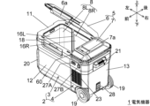
- FIG. 1 is a perspective view of an electric device 1 according to a first embodiment of the present invention, seen from the front upper side, with a first lid 6 open.
- FIG. FIG. 2 is a perspective view of the electric device 1 as viewed from the upper right front, with a partition plate 70 removed from FIG. 1 .
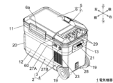
- FIG. 2 is a perspective view of the electric device 1 as viewed from the front upper right with a second cover 7 open.
- 4 is a perspective view of the electric device 1 as viewed from the upper right front, with the battery pack 29 removed from FIG. 3 .
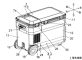
- FIG. FIG. 2 is a perspective view of the electric device 1 as viewed from the upper right rear side.
- FIG. FIG. 2 is a simplified block diagram of the mechanical configuration of the electrical device 1.
- FIG. 1 is a perspective view of an electric device 1 according to a first embodiment of the present invention, seen from the front upper side, with a first lid 6 open.
- FIG. FIG. 2 is a perspective view of the electric device 1 as viewed from
- FIG. 2 is a circuit block diagram of the electrical device 1, showing a state in which an ACDC conversion circuit (AC adapter) 82 is connected as an external power source and battery packs 29a and 29b are attached.
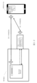
- 1A is a schematic diagram showing that when wireless communication is established between one of the battery packs 29a, 29b attached to the electric device 1 and the mobile terminal 150, wireless communication between the other of the battery packs 29a, 29b and the mobile terminal 150 cannot be established.
- 1B to 1D are diagrams showing screens of the mobile terminal 150 for inputting an authentication code when wirelessly connecting to the electric device 1.
- 1E is a diagram showing a screen of the mobile terminal 150 when setting the operation of the electric device 1.
- 3 is a control flowchart of the electrical device 1.
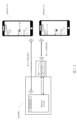
- FIG. 4 is a schematic diagram showing an electric device 1 according to a second embodiment of the present invention.
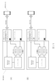
- FIG. 11 is a schematic diagram showing an electric device 1 according to a third embodiment of the present invention.
- FIG. 11 is a schematic diagram showing an electric device 1 according to a third embodiment of the present invention.
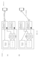
- FIG. 11 is a schematic diagram showing an electric device 1 according to a fourth embodiment of the present invention.
- FIG. 11 is a schematic diagram showing an electric device 1 according to a fourth embodiment of the present invention.
- FIG. 11 is a schematic diagram showing an electric device 1 according to a fifth embodiment of the present invention.
- the present embodiment relates to an electric device 1.
- the electric device 1 is configured as a portable cooler/warmer (cold storage or warm storage) having a cooling and heating function.
- Figures 1 to 6 show the external appearance of electrical device 1.
- Figure 1 and other figures define the mutually orthogonal front-to-back, up-down, and left-to-right directions of electrical device 1.
- the front-to-back direction is the depth direction (short direction) of electrical device 1
- the left-to-right direction is the width direction (longitudinal direction) of electrical device 1
- the up-to-down direction is the height direction of electrical device 1.
- the electrical device 1 includes a main body 2.
- the main body 2 has a first main body portion 3 and a second main body portion 4 that is separate from the first main body portion 3.
- the first main body portion 3 and the second main body portion 4 are aligned in the left-right direction.
- the second main body portion 4 is located outside and to the right of the first main body portion 3.
- the first main body 3 has a left outer box 12.
- the left outer box 12 is, for example, a resin molded body that is approximately rectangular with an open top and forms the exterior of the first main body 3.
- the second main body 4 has a right outer box 13.
- the right outer box 13 is, for example, a resin molded body that is approximately rectangular with an open top and left side and forms the exterior of the second main body 4.
- the right outer box 13 is fixed and integrated with the right side surface of the left outer box 12 by screwing or the like.
- the main body 2 has a main frame 11.
- the main frame 11 is, for example, a resin molded body.
- the main frame 11 is a frame body that spans the upper part of the first main body part 3 and the second main body part 4, and has openings that respectively correspond to the first main body part 3 and the second main body part 4.
- the electrical device 1 includes a lid 5.
- the lid 5 is provided on the top of the main body 2 and can be opened and closed relative to the main body 2.
- the lid 5 includes a first lid 6 that opens and closes the first main body 3, and a second lid 7 that opens and closes the second main body 4 (opens and closes the battery pack storage section 22).
- the first lid body 6 is rotatably connected to the rear end of the main frame 11 by a first hinge mechanism 25.
- the first lid body 6 has a handle portion 6a. The user can release the engagement of the first lid body 6 with the main frame 11 by rotating the handle portion 6a of the first lid body 6 in the closed state shown in FIG. 3 forward, and then hold the handle portion 6a to open the first lid body 6 as shown in FIG. 1.
- the second cover 7 is rotatably connected to the rear end of the main frame 11 by the second hinge mechanism 26.
- the second cover 7 has a handle 7a. The user can release the lock of the second cover 7 by rotating the handle 7a of the second cover 7 in the closed state shown in FIG. 1 upward, and then hold the handle 7a to open the second cover 7 as shown in FIG. 3.
- the electrical device 1 has a pair of left and right handles 21, and also has multiple (e.g., four) legs 35 at the bottom that serve as grounding parts. A user can lift the electrical device 1 by holding the left and right handles 21 and move the electrical device 1.
- the electrical device 1 has casters 19 and a movable handle (carry handle) 20.
- the casters 19 are provided at the front and rear of the lower right part of the main body 2.
- the rotation axis direction of the casters 19 is parallel to the left-right direction.
- the movable handle 20 is rotatably provided on the left side of the main body 2.
- the rotation axis direction of the movable handle 20 is parallel to the left-right direction.
- the user can use the casters 19 to move the electrical device 1 by rotating the movable handle 20 upward and holding the movable handle 20 to lift the left part of the main body 2 off the ground.
- the electrical device 1 has a USB terminal 27A and a cigarette lighter socket 27B at the top of the front of the second main body 4, and an external power input terminal 28 as a power connection part at the bottom of the right side of the second main body 4.
- the electrical device 1 can supply DC 5V to a device connected to the USB terminal 27A (hereinafter referred to as a "USB-connected device").
- the cigarette lighter socket 27B is an example of an external output part.
- the electrical device 1 can supply DC 12V to an external device connected to the cigarette lighter socket 27B (hereinafter also referred to as a "cigarette lighter-connected device").
- the external power input terminal 28 is an example of an external power connection part, and can be connected to an in-vehicle power source or an AC adapter alternatively.
- the electrical device 1 can input DC power from the outside via the external power input terminal 28.
- the electrical device 1 operates using the DC power or the power of the battery pack 29.
- the battery pack 29 is detachably attached to an electric tool or an electric work machine and can supply power.
- the rated voltage of the battery pack 29 is, for example, 18V.
- the electrical device 1 has a fan inside the right outer case 13. This fan generates fan wind that cools the cooling mechanism described below (particularly the condenser 42 shown in FIG. 7).
- An intake port 23 for taking in the fan wind is provided on the front side of the right outer case 13.
- An exhaust port 24 for expelling the fan wind is provided on the rear side of the right outer case 13. The fan wind flows in the front-to-rear direction from the intake port 23 to the exhaust port 24. Note that the intake and exhaust front-to-back relationship may be reversed.
- the first main body portion 3 has a storage chamber 8 (storage section).
- the storage chamber 8 has a right room 8R which is a first storage chamber (first storage section) and a large room, and a left room 8L which is a second storage chamber (second storage section) and a small room.
- the right room 8R and the left room 8L are adjacent to each other and are separated (partitioned) by a removable partition plate 70.
- the first main body 3 has a right side member 16R, a left side member 16L, and a rail member 18, which are components of the storage chamber 8.
- the right side member 16R and the left side member 16L are metal plates such as aluminum, and are U-shaped when viewed from above and below.
- Refrigerant pipes 45R, 45L, which appear in Figure 7, are provided around the right side member 16R and the left side member 16L.
- the rail members 18 guide the attachment and removal of the partition plate 70.
- the rail members 18 are provided in two gaps between the right side member 16R and the left side member 16L.
- the rail members 18 also serve to connect the right side member 16R and the left side member 16L.
- the rail members 18 are fixed to the main frame 11 by screws (not shown).
- the combined right side member 16R, left side member 16L, and rail member 18 are fitted from above into a bottom member (not shown), which is, for example, a resin molded body, and together with the bottom member, form the inner box of the first main body part 3.
- the space between this inner box and the left outer box 12 is filled with a heat insulating material (not shown), such as urethane foam. This heat insulating material hardens after filling, so it fixes the inner box to the left outer box 12 and also serves to fix the main frame 11.
- the second main body 4 has a battery pack storage section 22 (battery box) capable of storing a battery pack.
- the battery pack storage section 22 is, for example, a resin molded body that has an opening on the upper side and is entirely closed except for one part.
- the battery pack storage section 22 is inserted from above into the opening of the main frame 11 and fixed to the main frame 11 by screws.
- the aforementioned second lid 7 is a lid that can switch the opening of the battery pack storage section 22 between an open state and a closed state separately from the storage chamber 8.
- the battery pack storage section 22 has two battery pack attachment sections 22a (battery pack connection sections) on the left side wall.
- One of the two battery pack attachment sections 22a corresponds to the first battery pack connection section, and the other corresponds to the second battery pack connection section.
- Each battery pack attachment section 22a can detachably attach (connect) a battery pack 29 as shown in FIG. 3.
- Each battery pack attachment section 22a serves as an external output section when charging the attached battery pack 29.
- the battery pack 29 is, for example, a battery pack for a power tool with a rated output voltage of 18V.
- An electrical device 1 without a battery pack 29 attached corresponds to the "electrical device main body" of the present invention, and an electrical device 1 with a battery pack 29 attached corresponds to the "electrical device" of the present invention.
- the electrical device 1 is equipped with a setting unit 60.
- the setting unit 60 is provided at the upper right front end of the main body 2 and faces in an upward forward direction. Using the setting unit 60, the user can turn the power of the electrical device 1 on and off, drive and stop the cooling/heating functional load unit 115 described below, supply and stop electricity to the cigarette lighter-connected device, and set the temperatures of the right room 8R and the left room 8L individually.
- FIG. 7 is a simplified block diagram of the mechanical configuration of the electrical device 1.
- the electrical device 1 includes a compressor 41, a condenser 42, a capillary tube 43, refrigerant tubes 44, 45R, 45L, and valves V1 and V2 as a cooling mechanism.
- the compressor 41, the condenser 42, and the capillary tube 43 are provided in the second main body portion 4.
- the compressor 41 has a motor, compresses the refrigerant, and outputs (discharges) it as a high-temperature, high-pressure gas.
- the compressor is a load (conversion unit) that converts the power supplied from the battery pack 29 into heat, and is also a load unit that is driven by the power supplied from the battery pack 29.
- the condenser 42 releases the heat of the refrigerant output from the compressor 41 and discharges the refrigerant as a liquid.
- the capillary tube 43 creates resistance to the flow of the refrigerant liquefied in the condenser 42, reducing the pressure and sending it to the inlet side of the valves V1 and V2 in the subsequent stage.
- the capillary tube 43 also forms part of the refrigerant pipe.
- Refrigerant pipe 45R is provided corresponding to right room 8R, and refrigerant pipe 45L is provided corresponding to left room 8L.
- Refrigerant pipes 45R, 45L extend along the outer surfaces of right side member 16R and left side member 16L shown in Figures 1 and 2, respectively, and merge at their ends.
- Refrigerant pipe 44 connects the junction of refrigerant pipes 45R, 45L to the inlet of compressor 41. As the refrigerant passes around storage chamber 8, it absorbs heat from storage chamber 8 and evaporates, becoming a gas.
- the right refrigerant pipe 45R and the left refrigerant pipe 45L are independent of each other. That is, the right refrigerant pipe 45R is provided to primarily cool the right room 8R, and the left refrigerant pipe 45L is provided to primarily cool the left room 8L.
- Each of the valves V1 and V2 is an electromagnetic valve, with one flow path connectable to the outlet side and one flow path connectable to the inlet side (1-in-1-out type).
- the valves V1 and V2 are connected to the right refrigerant pipe 45R and the left refrigerant pipe 45L, respectively, and can individually adjust (open/close) the flow of refrigerant in the right refrigerant pipe 45R and the left refrigerant pipe 45L.
- the electrical device 1 has heaters (e.g., wire heaters) provided corresponding to the left and right chambers 8L and 8R, respectively.
- the heaters are provided to cover the refrigerant pipes 45L and 45R, respectively.
- FIG 8 is a circuit block diagram of the electrical device 1, in which an AC-DC conversion circuit (AC adapter) 82 is connected as an external power source and battery packs 29a and 29b are attached.
- AC-DC conversion circuit AC adapter
- the two battery packs 29 shown in Figure 3 are distinguished as battery packs 29a and 29b.
- One of the battery packs 29a and 29b corresponds to the first battery pack, and the other corresponds to the second battery pack.
- Figure 8 mainly shows the circuit parts related to communication between the electrical device 1 and the battery packs 29a and 29b, and does not show the compressor 41 shown in Figure 7 or the power supply path to the compressor 41.
- the mode of current supply to the compressor 41 may be the same as in the conventional case.
- the voltage of the AC power source 81 (e.g., 100V AC) is converted to, e.g., 12V DC by the ACDC conversion circuit (AC adapter) 82 and input to the electrical device 1.
- the ACDC conversion circuit 82 is not limited to being external, and the electrical device 1 may have a built-in function equivalent to the ACDC conversion circuit 82.
- the charging control circuit 83 converts the output voltage of the ACDC conversion circuit 82 to a voltage suitable for charging the battery pack 29a or 29b and supplies it to the battery pack 29a or 29b.
- the charging control circuit 83 is an example of a charging unit of the present invention.
- the control power supply generating unit 84 converts the output voltage of the ACDC conversion circuit 82 into a power supply voltage for the cold/warm control MCU 85, the battery control MCU 87, etc., and supplies it to the cold/warm control MCU 85, the battery control MCU 87, etc.
- the cold/warm control MCU 85 controls the cold/warm control circuit 86.
- the cold/warm control circuit 86 controls the operation of the compressor 41 shown in FIG. 7.
- Switches SW3 to SW7 are provided in the setting unit 60 shown in FIG. 1 etc., and are operated by the user.
- Switch SW3 is a switch that switches the cooling or heating operation of the electrical device 1 on and off.
- Switch SW4 is a switch that is operated to increase the set temperature of the left room 8L.
- Switch SW5 is a switch that is operated to decrease the set temperature of the left room 8L.
- Switch SW6 is a switch that is operated to increase the set temperature of the right room 8R.
- Switch SW7 is a switch that is operated to decrease the set temperature of the right room 8R.
- the battery control MCU 87 controls communication with the battery packs 29a, 29b and charging of the battery packs 29a, 29b.
- the battery control MCU 87 may be integrated with the cold/warm control MCU 85.
- the battery control MCU 87 is configured to be capable of wireless communication with the mobile terminal 150 shown in FIG. 9 via the MCU 104 with wireless communication function of the battery pack 29a or 29b.
- the mode switching unit 88 switches between receiving an analog signal indicating the temperature of the battery pack 29a from the battery pack 29a via the LS terminal (analog communication) and performing digital communication with the battery pack 29a via the LS terminal.
- the communication control unit 89 controls digital communication between the battery control MCU 87 and the battery pack 29a (MCU 104 with wireless communication function).
- the battery temperature AD detection unit 90 receives an analog signal indicating the temperature of the battery pack 29a and transmits it to the battery control MCU 87.
- the mode switching unit 91 switches between receiving an analog signal indicating the type of battery pack 29a (rated voltage, etc.) from the battery pack 29a via the T terminal (analog communication) and performing digital communication with the battery pack 29a via the T terminal.
- the communication control unit 92 controls digital communication between the battery control MCU 87 and the battery pack 29a (MCU 104 with wireless communication function).
- the battery identification AD detection unit 93 receives an analog signal indicating the type of battery pack 29a and transmits it to the battery control MCU 87.
- the mode switching unit 94 switches between receiving an analog signal indicating the temperature of the battery pack 29b from the battery pack 29b via the LS terminal (analog communication) and performing digital communication with the battery pack 29b via the LS terminal.
- the communication control unit 95 controls digital communication between the battery control MCU 87 and the battery pack 29b (MCU 104 with wireless communication function).
- the battery temperature AD detection unit 96 receives an analog signal indicating the temperature of the battery pack 29b and transmits it to the battery control MCU 87.
- the mode switching unit 97 switches between receiving an analog signal indicating the type of battery pack 29b (rated voltage, etc.) from battery pack 29b via the T terminal (analog communication) and performing digital communication with battery pack 29b via the T terminal.
- the communication control unit 98 controls digital communication between the battery control MCU 87 and battery pack 29b (MCU 104 with wireless communication function).
- the battery identification AD detection unit 99 receives an analog signal indicating the type of battery pack 29b and transmits it to the battery control MCU 87.
- the LS terminal and T terminal on the electrical device 1 side are examples of main body side communication terminals.
- the LS terminal and T terminal on the battery packs 29a, 29b side are examples of battery side communication terminals.
- the analog signal indicating the temperature of the battery packs 29a, 29b and the analog signal indicating the type of the battery packs 29a, 29b (rated voltage, etc.) are examples of information relating to the battery packs 29a, 29b, respectively.
- information about the main body of the electrical device 1 such as the model name, model number, and current control state (e.g., set temperature and charging progress), is transmitted to the battery pack 29a or 29b, and then transmitted (transferred) from the battery pack 29a or 29b to the mobile terminal 150 shown in FIG. 9.
- a digital signal for changing the control of the electrical device 1 is transmitted from the mobile terminal 150 to the battery pack 29a or 29b as information about the electrical device 1, and then transmitted (transferred) to the electrical device 1 by digital communication via the LS terminal and the T terminal.
- Each of the battery packs 29a and 29b has a battery cell 101, a battery protection control unit 102, a power generation unit 103, an MCU 104 with wireless communication function, a communication control unit 105, a battery temperature monitoring unit 106, a battery identification unit 107, and a wireless function on/off switch SW.
- the battery cell 101 is a secondary battery cell such as a lithium ion battery.
- the battery protection control unit 102 is an IC for protecting the battery cell 101.
- the power generation unit 103 converts the output voltage of the battery cell 101 into a power supply voltage for an MCU 104 with wireless communication function, etc., and supplies it to the MCU 104 with wireless communication function, etc.
- the MCU 104 with wireless communication function is the control unit of the battery pack and also the wireless communication unit of the battery pack.
- the MCU 104 with wireless communication function has a short-range wireless communication function such as Bluetooth (registered trademark), and wirelessly communicates with the mobile terminal 150 shown in FIG. 9.
- the communication control unit 105 controls digital communication between the MCU 104 with wireless communication function and the electrical device 1 (battery control MCU 87).
- the battery temperature monitoring unit 106 includes a temperature detection element such as a thermistor arranged near the battery cell 101, and outputs an analog signal (analog voltage) corresponding to the temperature of the battery cell 101 to the LS terminal.
- the battery identification unit 107 includes an identification resistor corresponding to the rated voltage of the battery pack to which it belongs, and outputs an analog signal (analog voltage) corresponding to the rated voltage to the T terminal.
- the wireless function on/off switch SW is an operation unit that allows the user to switch the wireless communication function of the MCU 104 with wireless communication function on/off, i.e., between a wireless communication standby state and a non-standby state. For example, by pressing and holding the wireless function on/off switch SW, the MCU 104 with wireless communication function enters a wireless communication standby state.
- FIG. 9(A) is a schematic diagram showing that when wireless communication is established between one of the battery packs 29b, 29b attached to the electrical device 1 and the mobile terminal 150, wireless communication between the other of the battery packs 29b, 29b and the mobile terminal 150 cannot be established.
- the battery control MCU 87 is configured to allow wireless communication between only one of the battery packs 29b, 29b and the external device, the mobile terminal 150, in order to prevent communication confusion.
- the mobile terminal 150 is a smartphone, tablet terminal, or the like.
- FIGS. 9(B) to (D) are diagrams showing screens of the mobile terminal 150 for inputting an authentication code when wirelessly connecting to the electrical device 1.
- a management application (hereinafter, “management application") for managing the electrical device 1 is installed in the mobile terminal 150.
- management application for managing the electrical device 1 is installed in the mobile terminal 150.
- an authentication code is requested.
- the control of the electrical device 1 can be changed from the mobile terminal 150 using the function of the management application.
- the send button is inactive because the input of the authentication code has not been completed, and the send button becomes active when the input of the authentication code is completed as shown in FIG. 9(D).
- a message such as "Authentication code "ABC123" has been registered” is displayed (not shown).
- the authentication code may be set to be input every time, or the mobile terminal 150 that has been successfully authenticated once may store the authentication code in a non-volatile memory in the battery control MCU 87 of the electrical device 1, so that input of the authentication code is not required when connecting for the second time or later.
- the battery pack that relays communication between the electrical device 1 and the mobile terminal 150 may be stored in the non-volatile memory of the battery control MCU 87.
- FIG. 9(E) is a diagram showing a screen of the mobile terminal 150 when setting the operation of the electric device 1. If authentication is successful, the screen shown in FIG. 9(E) appears, and the control of the electric device 1 can be changed from the management application of the mobile terminal 150. An example of the operation method will be described below.
- the L button and the R button it is possible to select whether the left room 8L or the right room 8R is to be the target of the temperature setting change. In the illustrated state, the right room 8R is selected.
- the temperature of the selected room is displayed as the current temperature.
- the temperature of the selected room is an example of detection information detected regarding the electric device 1, and is obtained from the electric device 1 by communication.
- the set temperature can be raised or lowered by using the + button and the - button.
- the set temperature is displayed between the + button and the - button. After setting, by tapping the send button, the set temperature is sent to the electric device 1 by communication, and the set temperature of the electric device 1 is changed. After setting is completed, a message such as "Room R/Set to 10°C" is displayed (not shown).
- the management app has a function of setting the operation related to charging the battery packs 29a and 29b in the electrical device 1.
- the management app displays on the screen of the mobile terminal 150 the current remaining charge (%) of the battery packs 29a and 29b, which of the battery packs 29a and 29b is being charged, and the current settings related to charging.
- These pieces of information are examples of information detected about the battery packs, and are obtained from the battery packs through communication.
- the settings related to charging include, for example, a mode in which the battery pack with the lowest remaining charge is charged first, a mode in which the battery pack with the highest remaining charge is charged first, a mode in which the two battery packs are charged sequentially while making the remaining charges of the two battery packs equal, a mode in which charging is stopped at a predetermined remaining charge before full charge, a save mode (a charging mode that puts less strain on the battery packs), and the like, and the user can select any mode by operating the management app.
- the settings related to charging transmitted from the mobile terminal 150 to the electrical device 1 are examples of setting information.
- Figure 10 is a control flowchart for electrical device 1. Assume that a DC voltage is input to electrical device 1 from ACDC conversion circuit 82.
- the battery control MCU 87 sets both the LS terminal and the T terminal of each of the two battery pack mounting sections 22a to non-communication mode (S1), detects the connection of the battery pack mounting section 22a (S3), and starts charging (S5).
- the non-communication mode the LS terminal and the T terminal become terminals that receive an analog signal indicating the temperature and an analog signal indicating the type from the battery pack, respectively (communicate information about the battery pack).
- the non-communication mode in FIG. 10 is an example of the battery information communication mode.
- the processing from S5 onwards is performed while the battery pack 29a or 29b is being charged.
- the battery control MCU 87 sets the LS terminal and T terminal of each of battery packs 29a and 29b to communication mode (S9), acquires information about battery pack 29a via digital communication (S11), and acquires information about battery pack 29b via digital communication (S13).
- the battery control MCU 87 turns off the wireless communication permission flag of battery pack 29b (S17) and sends a communication connection waiting signal to battery pack 29a (S19).
- the battery control MCU 87 sends a communication connection waiting signal to battery pack 29a (S19).
- the battery control MCU 87 sends a communication connection waiting signal to battery pack 29b (S23).
- the wireless communication permission flag is a flag that indicates whether the battery pack attached to the electrical device 1 is allowed to wirelessly communicate with the management app of the mobile terminal 150 to change the control of the electrical device 1 (remote control of the electrical device 1), and is stored in non-volatile memory by the battery control MCU 87.
- the battery control MCU 87 sets the LS terminal and T terminal of the battery pack 29a to communication mode (S27), acquires information about the battery pack 29a through digital communication (S29), and transmits a communication connection waiting signal to the battery pack 29a (S31). Before S31, the battery control MCU 87 may turn on the wireless communication permission flag of the battery pack 29a and store it in non-volatile memory.
- the battery control MCU 87 sets the LS terminal and T terminal of battery pack 29b to communication mode (S35), acquires information about battery pack 29b through digital communication (S37), and transmits a communication connection waiting signal to battery pack 29b (S39). Before S39, the battery control MCU 87 may turn on the wireless communication permission flag of battery pack 29b and store it in non-volatile memory.
- each of the battery packs 29a and 29b When each of the battery packs 29a and 29b receives the communication connection waiting signal, it enters the same state as when the wireless function on/off switch SW is pressed and held, i.e., a wireless communication waiting state.
- the battery control MCU 87 acquires the communication data from the management app through digital communication with the communication battery pack (S43) and changes the temperature setting of the electrical device 1, etc., as necessary (S45).
- the battery control MCU 87 sets the LS terminal and T terminal of the communication battery pack to non-communication mode (S47), reads the temperature of the communication battery pack from the analog signal indicating the temperature of the communication battery pack (S49), sets the LS terminal and T terminal of the communication battery pack to communication mode (S51), and returns to S41.
- the communication mode information about the main body of the electrical device 1, i.e., the model name, model number, current control status (e.g., current internal temperature, set temperature, charging progress), etc., is transmitted as necessary from the electrical device 1 to the mobile terminal 150 via the communication battery pack, and is displayed on the screen of the mobile terminal 150.
- the communication mode is an example of a main body information communication mode.
- the battery control MCU 87 and the MCU 104 with wireless communication function of the communication battery pack may wait for communication data from the management app of the mobile terminal 150 while communicating with the battery control MCU 87 regarding charging. If the MCU 104 with wireless communication function of the communication battery pack receives communication data, such as a signal to change the control of the electrical device 1, from the management app of the mobile terminal 150 while communicating with the battery control MCU 87 regarding charging, it interrupts the communication regarding charging and relays the wireless communication between the mobile terminal 150 and the electrical device 1.
- communication data such as a signal to change the control of the electrical device 1
- the battery control MCU 87 is configured to be able to communicate wirelessly with the mobile terminal 150 via the MCU 104 with wireless communication function of the communication battery pack. Therefore, even if the electrical device 1 does not have a wireless communication unit as a main body, wireless communication with the mobile terminal 150 is possible via the communication battery pack, improving convenience. In particular, in both cases, when the communication battery pack is supplying power to the load unit and when the communication battery pack is being charged by the charging unit, the battery control MCU 87, which is the control unit, is configured to be able to communicate wirelessly with the mobile terminal 150, which is an external device, via the wireless communication unit of the communication battery pack.
- the battery control MCU 87 is configured to disable wireless communication between the other battery pack 29b, 29b and the mobile terminal 150 when wireless communication between one of the battery packs 29b, 29b and the mobile terminal 150 is established.
- the battery control MCU 87 sets one of the battery packs 29a, 29b to a wireless communication standby state and the other to a non-wireless communication standby state. This makes it possible to prevent confusion caused by both battery packs 29b, 29b simultaneously communicating wirelessly with the mobile terminal 150.
- the battery control MCU 87 is configured to be able to wirelessly communicate with the mobile terminal 150 via the MCU 104 with wireless communication function of the battery pack 29a or 29b while the battery pack 29a or 29b is being charged. This allows the control of the electrical device 1 to be changed from the mobile terminal 150 even while the battery pack 29a or 29b is being charged, thereby improving convenience.
- the battery control MCU 87 controls the LS terminal and T terminal of the communication battery pack to alternate between communication mode and non-communication mode. Therefore, in non-communication mode, an analog signal indicating the temperature of the communication battery pack is received to recognize the temperature of the communication battery pack and used to control charging of the communication battery pack, while in communication mode, a digital signal is received from the mobile terminal 150 via the communication battery pack to change the control of the electrical device 1, improving convenience.
- the battery control MCU 87 requests an authentication code from the management app of the mobile terminal 150, and inputting the correct authentication code is a necessary condition for the management app of the mobile terminal 150 to change the control of the electrical device 1. This reduces the risk that a third party who does not know the authentication code will remotely change the control of the electrical device 1.
- the battery control MCU 87 When the battery control MCU 87 detects the connection of the battery pack 29a or 29b, it transmits a communication connection waiting signal to the battery pack 29a or 29b, and can put the battery pack 29a or 29b into a wireless communication standby state. This eliminates the need for the user to operate the wireless function on/off switch SW of the battery pack 29a or 29b when remotely operating the electrical device 1 using the management app on the mobile terminal 150, improving convenience.
- the battery pack housing section 22 housing the battery packs 29a, 29b is closed by the second lid 7, so there is a significant advantage in not having to operate the wireless function on/off switch SW of the battery pack 29a or 29b.
- the MCU 104 with wireless communication function of the communication battery pack receives communication data from the management app of the mobile terminal 150 while communicating with the battery control MCU 87 regarding charging, it interrupts the communication regarding charging and relays the wireless communication between the mobile terminal 150 and the electrical device 1. Therefore, when communication data is not received from the management app of the mobile terminal 150, communication regarding charging is possible, improving convenience.
- the functions of the management app enable the mobile terminal 150 to display information related to the main body of the electric device 1, such as the model name and model number, the current control status (for example, the current internal temperature, the set temperature, and the charging progress), and also to display the current remaining charge (%) of the battery packs 29a, 29b, which of the battery packs 29a and 29b is being charged, and the current settings related to charging, and to remotely change the set temperature and charging settings of the electric device 1. This reduces the effort required for a user who is away from the electric device 1 to operate the setting unit 60 of the electric device 1, improving convenience.
- the electrical device 1 may have, for example, in the setting unit 60, a remote control permission setting unit that sets whether or not to allow the mobile terminal 150 to change the control.
- a remote control permission setting unit that sets whether or not to allow the mobile terminal 150 to change the control.
- the battery control MCU 87 does not send a communication connection waiting signal to the battery packs 29a and 29b. This prevents the battery packs 29a and 29b from going into a wireless communication standby state unnecessarily, and reduces power consumption of the battery packs 29a and 29b.
- FIG. 11 shows an electric device 1 according to embodiment 2.
- a battery pack 29a as a first battery pack and a battery pack 29b as a second battery pack are simultaneously attached to the electric device 1, and a battery control MCU 87 establishes wireless communication with a mobile terminal 150 via an MCU 104a with wireless communication function as a first wireless communication unit included in the battery pack 29a and an MCU 104b with wireless communication function as a second wireless communication unit included in the battery pack 29b.
- the battery control MCU 87 establishes a first wireless communication with a mobile terminal 150a as a first external device via an MCU 104a with wireless communication function possessed by the battery pack 29a, and establishes a second wireless communication with a mobile terminal 150b as a second external device via an MCU 104b with wireless communication function possessed by the battery pack 29b.
- the battery control MCU 87 is configured to control the compressor 41 as a load section according to instructions received from either the mobile terminal 150a or the mobile terminal 150b via either the first wireless communication or the second wireless communication.
- the mobile terminal 150a transmits a first instruction
- the battery control MCU 87 receives the first instruction, and controls the compressor 41 according to the first instruction.
- the mobile terminal 150b transmits a second instruction
- the battery control MCU 87 receives the second instruction from the mobile terminal 150b, overwrites the first instruction with the second instruction, and controls the compressor 41 according to the second instruction.
- the battery control MCU 87 transmits a notification to the battery pack 29b via the second wireless communication that it has received a first instruction from the battery pack 29a via the first wireless communication. Also, as shown in FIG. 11(C), the battery control MCU 87 transmits a notification to the battery pack 29a via the first wireless communication that it has received a second instruction from the battery pack 29b via the second wireless communication.
- the battery control MCU 87 is configured to output first battery pack information, which is information relating to the first battery pack, to the second battery pack, and/or output second battery pack information, which is information relating to the second battery pack, to the first battery pack.
- battery pack information may include, in addition to the information notifying that another instruction has been sent from another battery pack as described above, information indicating that another battery pack has been attached to the electrical device body and information indicating the remaining capacity of another battery pack.
- the battery control MCU 87 may be configured to control the compressor 41 only according to instructions received via either the first wireless communication or the second wireless communication.
- FIG. 12 shows an electric device 1 according to a third embodiment.
- a battery pack 29a is attached to the electric device 1, and a battery control MCU 87 of the electric device 1 establishes a first wireless connection with a mobile terminal 150a through an MCU 104a with a wireless communication function included in the battery pack 29a.
- the battery control MCU 87 of the electric device 1 also has a wireless communication function, and the battery control MCU 87 establishes a second wireless connection with the mobile terminal 150a through the wireless communication function included in the battery control MCU 87.
- the battery control MCU 87 is configured to control the compressor 41 according to an instruction received from the mobile terminal 150a through either the first wireless communication or the second wireless communication in a state in which the first wireless communication and the second wireless communication are established.
- the battery control MCU 87 with a wireless communication function is an example of a main body wireless communication unit.
- the battery control MCU 87 when the battery pack 29a is attached to the battery pack attachment section, the battery control MCU 87 is configured to be capable of first wireless communication with the mobile terminal 150a via the MCU 104a with wireless communication function of the battery pack 29a, and to be capable of second wireless communication with the mobile terminal 150a via the battery control MCU 87 of the electrical device body 1.
- the battery control MCU 87 is configured to maintain the second wireless communication when the first wireless communication is interrupted from a state in which the first wireless communication and the second wireless communication are established, the wireless communication with the mobile terminal 150a can be stably maintained.
- the battery control MCU 87 when the battery control MCU 87 is configured to establish the second wireless communication when the first wireless communication is interrupted from a state in which the first wireless communication is established but the second wireless communication is not established, the wireless communication with the mobile terminal 150a can be stably maintained.
- the battery control MCU 87 detects that the battery pack 29a in a state where wireless communication with the mobile terminal 150a has been established is attached to the battery pack attachment section, the battery control MCU 87 may be configured to output a command to the MCU 104a with wireless communication function of the battery pack 29a to cut off wireless communication between the battery pack 29a and the mobile terminal 150a, and establish or maintain wireless communication between the battery control MCU 87 and the mobile terminal 150a.
- the user may operate the mobile terminal 150a to disconnect the wireless communication between the battery pack 29a and the mobile terminal 150a and to instruct the battery control MCU 87 to establish or maintain wireless communication between the mobile terminal 150a and the battery control MCU 87.
- the battery control MCU 87 it is possible to reduce power consumption of the battery pack 29a due to wireless communication and to prevent the wireless connection from being suddenly disconnected.
- a battery pack 29a is attached to the electric device 1, and the battery control MCU 87 of the electric device 1 establishes a first wireless communication with the mobile terminal 150a via the MCU 104a with wireless communication function of the battery pack 29a. Furthermore, the battery control MCU 87 establishes a second wireless communication with the mobile terminal 150b via the wireless communication function of the battery control MCU 87.
- the battery control MCU 87 is configured to control the compressor 41 according to the first instruction when it receives a first instruction from the mobile terminal 150a, and to overwrite the first instruction with the second instruction and control the compressor 41 according to the second instruction when it receives a second instruction different from the first instruction from the mobile terminal 150b immediately thereafter.
- the battery control MCU may be configured to control the compressor 41 only according to instructions received via either the first wireless communication or the second wireless communication.
- Fig. 14 shows an electric device 1 according to a fourth embodiment.
- a battery pack 29a as a first battery pack and a battery pack 29b as a second battery pack are both attached to the electric device 1.
- Neither of the battery packs 29a and 29b has a wireless communication function.
- the compressor 41 is driven by power supplied from the battery pack 29a or the battery pack 29b.
- a switching unit 30a is provided between the first battery pack mounting unit and the compressor 41 as a first switching unit that switches whether the first battery pack mounting unit is connected to or disconnected from the compressor 41.
- a switching unit 30b is provided between the second battery pack mounting unit and the compressor 41 as a second switching unit that switches whether the second battery pack mounting unit is connected to or disconnected from the compressor 41.
- the battery control MCU 87 is configured to control the compressor 41, the switching unit 30a, and the switching unit 30b.
- both the battery pack 29a and the battery pack 29b are in a nearly fully charged state. Then, the battery pack 29a is first connected to the electrical device 1, the switching unit 30a is connected, and power supply from the battery pack 29a to the compressor 41 is started. After that, the battery pack 29b is connected to the electrical device 1, but the switching unit 30b is cut off. Then, as shown in FIG. 14(B), when the remaining capacity of the battery pack 29a becomes low and the voltage of the battery pack 29a drops to the cut-off threshold VS1, the switching unit 30a is cut off.
- the cut-off threshold VS1 is set to a voltage slightly higher than the voltage at which the battery pack attached to the battery pack attachment section becomes over-discharged. When the switching unit 30a is cut off, the switching unit 30b is next connected, and power supply from the battery pack 29b to the compressor 41 is started.
- the cut-off threshold VS1 is an example of a first cut-off threshold.
- FIG. 15 shows a state in which a battery pack 29a having an MCU 104a with wireless communication function and a battery pack 29b without wireless communication function are simultaneously attached to an electrical device 1 as a first battery pack.
- FIG. 15(A) both the battery packs 29a and 29b are almost fully charged, but the battery pack 29a is connected to the electrical device 1 first, the switching unit 30a is connected, and power supply from the battery pack 29a to the compressor 41 is started. After that, the battery pack 29b is connected to the electrical device 1, but the switching unit 30b is cut off. After that, as shown in FIG. 15(B), when the remaining capacity of the battery pack 29a becomes low and the voltage of the battery pack 29a drops to the cutoff threshold VS2, the switching unit 30a is cut off.
- a voltage higher than the cutoff threshold VS1 is set as the cutoff threshold VS2. This makes it possible to prevent the wireless communication connection via the wireless communication unit of the first battery pack from being suddenly cut off.
- the cutoff threshold VS2 is an example of a second cutoff threshold.
- the battery control MCU is configured to cut off the first switching unit when the voltage of the battery pack 29a equipped with the wireless communication unit drops to the second cut-off threshold from a state in which the first switching unit is connected, and to connect the second switching unit after cutting off the first switching unit. This maintains the supply of power to the compressor 41.
- the battery control MCU is configured to cut off the first switching unit when the voltage of the battery pack 29a equipped with the wireless communication unit drops to the second cut-off threshold from a state in which the first switching unit and the first switching unit are connected, and to maintain the connection of the second switching unit thereafter. This maintains the supply of power to the compressor 41.
- the battery control MCU is configured to detect whether a battery pack having a wireless connection part is attached to battery pack attachment part 1 or battery pack attachment part 2 by communicating with each battery pack.
- FIG. 16 shows an electric device 1 according to a fifth embodiment, which is a partial modification of the electric device 1 according to the fourth embodiment.
- a battery pack 29a having an MCU 105a with wireless communication function as a first battery pack and a battery pack 29b having an MCU 105b with wireless communication function as a second battery pack are simultaneously mounted on the electric device 1.
- a description of the configuration and its operation common to the fourth embodiment will be omitted.
- both battery pack 29a and battery pack 29b are in a nearly fully charged state. Then, battery pack 29a is first connected to electrical device 1, switching unit 30a is connected, and power supply from battery pack 29a to compressor 41 is started. Then, a first wireless connection is established between battery control MCU 87 and mobile terminal 150 via battery pack 29a. After that, battery pack 29b is connected to electrical device 1, but switching unit 30b is cut off. Then, as shown in FIG. 15(B), when the remaining capacity of battery pack 29a becomes low and the voltage of battery pack 29a drops to cut-off threshold VS2, switching unit 30a is cut off.
- FIG 15 shows a state in which a battery pack 29a having an MCU 104a with wireless communication function and a battery pack 29b without wireless communication function are simultaneously attached to an electrical device 1 as a first battery pack.
- FIG 15 (A) both battery packs 29a and 29b are almost fully charged, but battery pack 29a is connected to electrical device 1 first, switching unit 30a is connected, and power supply from battery pack 29a to compressor 41 is started. After that, battery pack 29b is connected to electrical device 1, but switching unit 30b is cut off.
- Figure 15 (B) when the remaining capacity of battery pack 29a becomes low and the voltage of battery pack 29a drops to the cut-off threshold value VS2, switching unit 30a is cut off.
- switching unit 30a When switching unit 30a is cut off, switching unit 30b is next connected and power supply from battery pack 29b to compressor 41 is started.
- the first wireless communication is maintained for a while via battery pack 29a, but eventually the remaining capacity of battery pack 29a will decrease further, the voltage will drop to the cutoff threshold VS1, and the first wireless communication will be terminated.
- the battery control MCU 87 When the battery control MCU 87 detects that the voltage of the battery pack 29a has dropped to the cutoff threshold VS1 or that the first wireless communication has been terminated, it establishes a second wireless communication with the mobile terminal 150 via the MCU 104b with wireless communication function of the battery pack 29b, as shown in FIG. 16(B). This allows wireless communication between the battery control MCU 87 and the mobile terminal to be maintained.
- the battery control MCU 87 may be configured to establish the second wireless communication with the mobile terminal 150 via the MCU 104b with wireless communication function of the battery pack 29b when the voltage of the battery pack 29a drops to a switching threshold VS3, which is a voltage higher than the cutoff threshold VS1.
- the cutoff threshold VS1 and the switching threshold VS3 are both examples of a connection switching threshold.
- the electrical device of the present invention is not limited to a refrigerator/warmer, but may be a light having a load unit (conversion unit) that converts the power of a battery pack into light, or a radio or music player having a load unit (conversion unit) that converts the power of a battery pack into, for example, sound. Furthermore, the present invention can also be applied to fans and working machines having a load unit (motor, etc.) that converts the power of a battery pack into motive power.
Landscapes
- Engineering & Computer Science (AREA)
- Manufacturing & Machinery (AREA)
- Chemical & Material Sciences (AREA)
- Chemical Kinetics & Catalysis (AREA)
- Electrochemistry (AREA)
- General Chemical & Material Sciences (AREA)
- Power Engineering (AREA)
- Charge And Discharge Circuits For Batteries Or The Like (AREA)
Abstract
電池パックの無線通信部を介して外部機器と無線通信が可能であり、かつ電池パックを充電可能である電気機器本体、及び当該電気機器本体を有する電気機器を提供する。電池パック29がコンプレッサ41に電力を供給している場合と、電池パック29が充電制御回路83によって充電されている場合の、いずれの場合においても、電気機器本体1の電池制御MCUは、電池パック29の無線通信機能付きMCU104を介して、携帯端末150と無線通信可能に構成される。
Description
本発明は、電気機器本体及び電気機器に関する。
特許文献1は、2つの電池パックを充電可能な充電回路を有し、無線通信部を有さない電気機器本体としての冷温庫を開示する。特許文献2は、電池パックの無線通信部を介して外部機器と無線通信可能な制御部を有する電気機器本体としての電動工具を開示する。
本発明の第1の目的は、電池パックの無線通信部を介して外部機器と無線通信が可能であり、かつ電池パックを充電可能である電気機器本体、及び当該電気機器本体を有する電気機器を提供することにある。本発明の第2の目的は、電池パックの無線通信部を介して外部機器と無線通信が可能であり、かつ安定した無線通信が可能な電気機器本体、及び当該電気機器本体を有する電気機器を提供することにある。
本発明のある態様は、電気機器本体である。この電気機器本体は、電池セル及び無線通信部を有する電池パックを装着可能な電池パック装着部と、前記電池パック装着部に装着された前記電池パックから供給された電力を熱、光又は音に変換する負荷部と、前記電池パックを充電する充電部と、前記負荷部と前記充電部を制御する制御部と、を有する電気機器本体であって、前記電池パックが前記負荷部に電力を供給している場合と、前記電池パックが前記充電部によって充電されている場合の、いずれの場合においても、前記制御部は、前記電池パックの前記無線通信部を介して外部機器と無線通信可能に構成される、ことを特徴とする。
本発明の別の態様は、電気機器本体である。この電気機器本体は、第1電池パックを装着可能な第1電池パック装着部と、第2電池パックを装着可能な第2電池パック装着部と、前記第1電池パック装着部に装着された前記第1電池パック及び/又は前記第2電池パック装着にされた前記第2電池パックから供給された電力で駆動する負荷部と、前記第1電池パック装着部に装着された前記第1電池パックと前記負荷部を互いに接続するか遮断するかを切り替える第1切替部と、前記第2電池パック装着部に装着された前記第2電池パックと前記負荷部を互いに接続するか遮断するかを切り替える第2切替部と、前記負荷部、前記第1切替部及び前記第2切替部を制御する制御部と、を有する電気機器本体であって、前記第1電池パック装着部に前記第1電池パックとして無線通信部を備えていない電池パックが装着され、前記第2電池パック装着部に前記第2電池パックとして無線通信部を備えていない電池パックが装着された場合に、前記制御部は、前記第1電池パックの電圧が第1遮断閾値まで低下すると前記第1切替部を遮断し、前記第1電池パック装着部に前記第1電池パックとして無線通信部を備えた電池パックが装着され、前記第2電池パック装着部に前記第2電池パックとして無線通信部を備えていない電池パックが装着された場合に、前記制御部は、前記第1電池パックの電圧が前記第1遮断閾値よりも高い第2遮断閾値まで低下すると前記第1切替部を遮断するよう構成された、ことを特徴とする。
本発明の別の態様は、電気機器本体である。この電気機器本体は、電池セル及び無線通信部を有する電池パックを装着可能な電池パック装着部と、前記電池パック装着部に装着された前記電池パックから供給された電力を熱、光、音又は動力に変換する負荷部と、携帯端末と無線通信できるよう構成された本体無線通信部と、前記負荷部と前記本体無線通信部を制御する制御部と、を有する電気機器本体であって、前記電池パック装着部に前記電池パックが装着された場合に、前記制御部は、前記電池パックが有する前記無線通信部を介して携帯端末との第1の無線通信が可能であり、かつ、前記電気機器本体が有する前記本体無線通信部を介して前記携帯端末との第2の無線通信が可能に構成される、ことを特徴とする。
本発明によれば、電池パックの無線通信部を介して外部機器と無線通信が可能であり、かつ電池パックを充電可能である電気機器本体、及び当該電気機器本体を有する電気機器を提供することができる。あるいは、本発明によれば、電池パックの無線通信部を介して外部機器と無線通信が可能であり、かつ安定した無線通信が可能な電気機器本体、及び当該電気機器本体を有する電気機器を提供することができる。
(実施形態1)
本実施形態は、電気機器1に関する。電気機器1は、冷却及び加温機能を備えた可搬型の冷温庫(保冷又は保温庫)として構成される。
本実施形態は、電気機器1に関する。電気機器1は、冷却及び加温機能を備えた可搬型の冷温庫(保冷又は保温庫)として構成される。
図1~図6は、電気機器1の外観を示す。図1等により、電気機器1における互いに直交する前後、上下、左右の各方向を定義する。前後方向は電気機器1の奥行き方向(短手方向)であり、左右方向は電気機器1の幅方向(長手方向)であり、上下方向は電気機器1の高さ方向である。
電気機器1は、本体2を備える。本体2は、第1本体部3と、第1本体部3とは別の第2本体部4と、を有する。第1本体部3及び第2本体部4は、左右方向に並ぶ。第2本体部4は、第1本体部3の外側かつ右側に位置する。
第1本体部3は、左外箱12を有する。左外箱12は、上部が開放の略直方体の例えば樹脂成形体であり、第1本体部3の外装を構成する。第2本体部4は、右外箱13を有する。右外箱13は、上部及び左部が開放の略直方体の例えば樹脂成形体であり、第2本体部4の外装を構成する。右外箱13は、左外箱12の右側面に、ネジ止め等により固定、一体化される。
本体2は、メインフレーム11を有する。メインフレーム11は、例えば樹脂成形体である。メインフレーム11は、第1本体部3及び第2本体部4の上部に跨がる枠体であって、第1本体部3及び第2本体部4にそれぞれ対応する開口部を有する。
電気機器1は、蓋体5を備える。蓋体5は、本体2の上部に設けられて本体2に対して開閉可能である。蓋体5は、第1本体部3を開閉する第1蓋体6と、第2本体部4を開閉する(電池パック収容部22を開閉する)第2蓋体7と、を有する。
第1蓋体6は、図5等に示すように、第1ヒンジ機構25によってメインフレーム11の後端部に回動可能に連結される。第1蓋体6は、把手部6aを有する。ユーザは、図3に示す閉状態の第1蓋体6の把手部6aを前方に回動させることでメインフレーム11に対する第1蓋体6の係止を解除し、そのまま把手部6aを持って図1に示すように第1蓋体6を開けられる。
第2蓋体7は、図5等に示すように、第2ヒンジ機構26によってメインフレーム11の後端部に回動可能に連結される。第2蓋体7は、把手部7aを有する。ユーザは、図1に示す閉状態の第2蓋体7の把手部7aを上方に回動させることで第2蓋体7の係止を解除し、そのまま把手部7aを持って図3に示すように第2蓋体7を開けられる。
電気機器1は、左右一対の把手部21を備え、また底部に接地部となる複数の(例えば4つの)脚部35を備える。ユーザは、左右の把手部21を持って電気機器1を持ち上げて、電気機器1を移動可能である。
電気機器1は、キャスター19及び可動ハンドル(キャリーハンドル)20を有する。キャスター19は、本体2の右下部の前後にそれぞれ設けられる。キャスター19の回転軸方向は、左右方向と平行である。可動ハンドル20は、本体2の左側面に回動可能に設けられる。可動ハンドル20の回動軸方向は、左右方向と平行である。ユーザは、可動ハンドル20を上方に回動させ、可動ハンドル20を持って本体2の左部を地面から浮かせることで、キャスター19を利用して電気機器1を移動可能である。
電気機器1は、第2本体部4の前面上部にUSB端子27A及びシガーソケット27Bを有し、第2本体部4の右側面下部に電源接続部としての外部電源入力端子28を備える。電気機器1は、USB端子27Aに接続した機器(以下「USB接続機器」)に直流5Vを供給できる。シガーソケット27Bは、外部出力部の例示である。電気機器1は、シガーソケット27Bに接続された外部機器(以下「シガーソケット接続機器」とも表記)に直流12Vを供給できる。外部電源入力端子28は、外部電源接続部の例示であり、車載電源とACアダプタとを択一的に接続可能である。電気機器1は、外部電源入力端子28を介して外部から直流電力を入力できる。電気機器1は、当該直流電力又は電池パック29の電力によって動作する。電池パック29は、電動工具や電動作業機に着脱可能に装着して電力供給が可能なものである。電池パック29の定格電圧は、例えば18Vである。
図示は省略するが、電気機器1は、右外箱13内にファンを有する。このファンは、後述の冷却機構(特に図7に示す凝縮器42)を冷却するファン風を発生する。ファン風を取り込むための吸気口23が、右外箱13の前面に設けられる。ファン風を排出するための排気口24が、右外箱13の背面に設けられる。ファン風は、吸気口23から排気口24に向けて前後方向に流れる。なお、吸排気の前後関係は逆でもよい。
第1本体部3は、収容室8(収容部)を有する。収容室8は、第1収容室(第1収容部)かつ大部屋としての右部屋8Rと、第2収容室(第2収容部)かつ小部屋としての左部屋8Lと、を有する。右部屋8R及び左部屋8Lは、互いに隣接し、着脱可能な仕切板70によって隔てられる(仕切られる)。
第1本体部3は、収容室8の構成要素となる右側面部材16R、左側面部材16L、及びレール部材18を有する。右側面部材16R及び左側面部材16Lは、アルミ等の金属板であり、それぞれ上下方向から見るとU字型である。右側面部材16R及び左側面部材16Lの周囲に図7に現れる冷媒管45R、45Lが設けられる。
レール部材18は、仕切板70の着脱をガイドする。レール部材18は、右側面部材16R及び左側面部材16Lの間の2箇所の隙間にそれぞれ設けられる。レール部材18は、右側面部材16R及び左側面部材16Lを連結する役割も持つ。レール部材18は、図示しないネジによりメインフレーム11に固定される。
互いに組み合わされた右側面部材16R、左側面部材16L、レール部材18は、例えば樹脂成形体である図示しない底面部材に上方から嵌め込まれ、底面部材と共に第1本体部3の内箱となる。この内箱と左外箱12との間には、図示しない断熱材、例えば発泡ウレタンが充填される。この断熱材は、充填後に硬化するので、左外箱12に対して内箱を固定し、更にメインフレーム11を固定する役割も持つ。
図4に示すように、第2本体部4は、電池パックを収容可能な電池パック収容部22(バッテリボックス)を有する。電池パック収容部22は、上側に開口を有する他は全体的に閉じた形状の例えば樹脂成形体である。電池パック収容部22は、メインフレーム11の開口部に上方から挿入され、メインフレーム11にネジ止めにより固定される。前述の第2蓋体7は、収容室8とは別に電池パック収容部22の開口を開状態と閉状態で切り替え可能な蓋部である。
電池パック収容部22は、左側壁部に、2つの電池パック装着部22a(電池パック接続部)を有する。2つの電池パック装着部22aの一方が第1電池パック接続部、他方が第2電池パック接続部に対応する。各々の電池パック装着部22aは、図3に示すように電池パック29を着脱可能に装着(接続)できる。各々の電池パック装着部22aは、装着した電池パック29に充電する場合には外部出力部となる。装着した電池パック29に充電する場合、電池パック29は外部機器となる。電池パック29は、例えば定格出力電圧が18Vの電動工具用の電池パックである。電池パック29を装着していない電気機器1が本発明の「電気機器本体」に対応し、電池パック29を装着した電気機器1が本発明の「電気機器」に対応する。
電気機器1は、設定部60を備える。設定部60は、本体2の右上前端部に設けられ、前上方向に臨む。ユーザは、設定部60により、電気機器1の電源のオンオフ、後述の冷温機能負荷部115の駆動、停止、シガーソケット接続機器への通電、停止、及び、右部屋8Rと左部屋8Lの温度の個別設定等が可能である。
図7は、電気機器1の機械構成の簡易ブロック図である。電気機器1は、冷却機構としてのコンプレッサ41、凝縮器42、毛細管43(キャピラリーチューブ)、冷媒管44、45R、45L、バルブV1、V2を含む。コンプレッサ41、凝縮器42、毛細管43は、第2本体部4に設けられる。
コンプレッサ41は、モータを有し、冷媒を圧縮し、高温高圧の気体として出力(吐出)する。コンプレッサは、電池パック29から供給された電力を熱に変換する負荷部(変換部)であり、また電池パック29から供給された電力で駆動する負荷部である。凝縮器42は、コンプレッサ41から出力された冷媒の熱を放出し、冷媒を液体として排出する。毛細管43は、凝縮器42で液化された冷媒の流れに抵抗を生じさせ、圧力を低下させて後段のバルブV1、V2の入口側に送出する。なお、毛細管43も冷媒管の一部を成す。
冷媒管45Rは右部屋8Rに対応して設けられ、冷媒管45Lは左部屋8Lに対応して設けられる。冷媒管45R、45Lは、それぞれ図1及び図2に示す右側面部材16R、左側面部材16Lの外面に沿って延び、その先で合流する。冷媒管44は、冷媒管45R、45Lの合流部とコンプレッサ41の入口とを接続する。冷媒は、収容室8の周囲を通る過程で収容室8から熱を奪って蒸発し、気体となる。
右冷媒管45Rと左冷媒管45Lは、互いに独立している。すなわち、右冷媒管45Rは右部屋8Rを主に冷却するように設けられ、左冷媒管45Lは左部屋8Lを主に冷却するよう設けられる。
バルブV1、V2の各々は、電磁バルブであり、出口側に接続可能な流路が1本、入口側に接続可能な流路が1本(1in1outタイプ)である。バルブV1、V2は、それぞれ右冷媒管45R及び左冷媒管45Lに接続され、右冷媒管45R及び左冷媒管45Lの冷媒の流れを個別に調整(開閉)可能である。
図示は省略するが、電気機器1は、左部屋8L、右部屋8Rに対応してそれぞれ設けられたヒータ(例えばワイヤヒータ)を有する。ヒータは、それぞれ冷媒管45L、45Rを覆うように設けられる。
図8は、電気機器1の回路ブロック図であって、外部電源としてACDC変換回路(ACアダプタ)82を接続し、かつ電池パック29a、29bを装着した状態の回路ブロック図である。図8において、図3に示す2つの電池パック29をそれぞれ電池パック29a、29bとして区別する。電池パック29a、29bの一方が第1電池パック、他方が第2電池パックに対応する。図8では、電気機器1と電池パック29a、29bとの通信に係る回路部分を主に示し、図7に示すコンプレッサ41や、コンプレッサ41への電力供給経路等の図示は省略している。コンプレッサ41への通電態様は従来と同じでよい。
交流電源81の電圧(例えば交流100V)は、ACDC変換回路(ACアダプタ)82により例えば直流12Vに変換され、電気機器1に入力される。なお、ACDC変換回路82は外付けに限定されず、ACDC変換回路82に相当する機能を電気機器1が内蔵してもよい。充電制御回路83は、ACDC変換回路82の出力電圧を電池パック29a又は29bの充電に適した電圧に変換して電池パック29a又は29bに供給する。充電制御回路83は、本発明の充電部の一例である。
制御用電源生成部84は、ACDC変換回路82の出力電圧を冷温制御MCU85や電池制御MCU87等の電源電圧に変換し、冷温制御MCU85や電池制御MCU87等に供給する。冷温制御MCU85は、冷温制御回路86を制御する。冷温制御回路86は、図7に示すコンプレッサ41の駆動を制御する。
スイッチSW3~SW7は、図1等に示す設定部60に設けられ、ユーザが操作するスイッチである。スイッチSW3は、電気機器1の冷却ないし加温動作のオンオフを切り替えるスイッチである。スイッチSW4は、左部屋8Lの設定温度を上げる操作をするスイッチである。スイッチSW5は、左部屋8Lの設定温度を下げる操作をするスイッチである。スイッチSW6は、右部屋8Rの設定温度を上げる操作をするスイッチである。スイッチSW7は、右部屋8Rの設定温度を下げる操作をするスイッチである。
電池制御MCU87は、電池パック29a、29bとの通信や電池パック29a、29bの充電に係る制御を行う。電池制御MCU87は、冷温制御MCU85と共に電気機器1の制御部を構成する。電池制御MCU87は冷温制御MCU85と一体でもよい。電池制御MCU87は、電池パック29a又は29bの無線通信機能付きMCU104を介して図9に示す携帯端末150との無線通信が可能に構成される。
モード切替部88は、LS端子を介して電池パック29aから電池パック29aの温度を示すアナログ信号を受信するか(アナログ通信するか)、LS端子を介して電池パック29aとデジタル通信を行うか、を切り替える。通信制御部89は、電池制御MCU87と電池パック29a(無線通信機能付きMCU104)との間のデジタル通信を制御する。電池温度AD検出部90は、電池パック29aの温度を示すアナログ信号を受信し、電池制御MCU87に送信する。
モード切替部91は、T端子を介して電池パック29aから電池パック29aの種別(定格電圧等)を示すアナログ信号を受信するか(アナログ通信するか)、T端子を介して電池パック29aとデジタル通信を行うか、を切り替える。通信制御部92は、電池制御MCU87と電池パック29a(無線通信機能付きMCU104)との間のデジタル通信を制御する。電池識別AD検出部93は、電池パック29aの種別を示すアナログ信号を受信し、電池制御MCU87に送信する。
モード切替部94は、LS端子を介して電池パック29bから電池パック29bの温度を示すアナログ信号を受信するか(アナログ通信するか)、LS端子を介して電池パック29bとデジタル通信を行うか、を切り替える。通信制御部95は、電池制御MCU87と電池パック29b(無線通信機能付きMCU104)との間のデジタル通信を制御する。電池温度AD検出部96は、電池パック29bの温度を示すアナログ信号を受信し、電池制御MCU87に送信する。
モード切替部97は、T端子を介して電池パック29bから電池パック29bの種別(定格電圧等)を示すアナログ信号を受信するか(アナログ通信するか)、T端子を介して電池パック29bとデジタル通信を行うか、を切り替える。通信制御部98は、電池制御MCU87と電池パック29b(無線通信機能付きMCU104)との間のデジタル通信を制御する。電池識別AD検出部99は、電池パック29bの種別を示すアナログ信号を受信し、電池制御MCU87に送信する。
電気機器1側のLS端子及びT端子は、本体側通信端子の例示である。電池パック29a、29b側のLS端子及びT端子は、電池側通信端子の例示である。電池パック29a、29bの温度を示すアナログ信号、及び電池パック29a、29bの種別(定格電圧等)を示すアナログ信号は、それぞれ電池パック29a、29bに関する情報の例示である。
LS端子及びT端子を介する電気機器1と電池パック29a又は29bとの間のデジタル通信では、電気機器1の本体に関する情報、すなわち機種名や型番、現在の制御状態(例えば設定温度や充電の進行状況)等が電池パック29a又は29bに送信され、電池パック29a又は29bから図9に示す携帯端末150に送信(転送)される。また、電気機器1に関する情報として電気機器1の制御を変更するためのデジタル信号が携帯端末150から電池パック29a又は29bに送信され、LS端子及びT端子を介するデジタル通信により電気機器1に送信(転送)される。
電池パック29a、29bはそれぞれ、電池セル101、電池保護制御部102、電源生成部103、無線通信機能付きMCU104、通信制御部105、電池温度監視部106、電池識別部107、無線機能オンオフスイッチSWを有する。
電池セル101は、リチウムイオン電池等の二次電池セルである。電池保護制御部102は、電池セル101の保護用のICである。電源生成部103は、電池セル101の出力電圧を無線通信機能付きMCU104等の電源電圧に変換し、無線通信機能付きMCU104等に供給する。
無線通信機能付きMCU104は、電池パックの制御部であると共に、電池パックの無線通信部である。無線通信機能付きMCU104は、Bluetooth(登録商標)等の近距離無線通信機能を有し、図9に示す携帯端末150と無線通信する。通信制御部105は、無線通信機能付きMCU104と電気機器1(電池制御MCU87)との間のデジタル通信を制御する。
電池温度監視部106は、電池セル101の近傍に配置されたサーミスタ等の温度検出素子を含み、電池セル101の温度に応じたアナログ信号(アナログ電圧)をLS端子に出力する。電池識別部107は、自身を有する電池パックの定格電圧等に応じた識別抵抗を含み、定格電圧等に応じたアナログ信号(アナログ電圧)をT端子に出力する。無線機能オンオフスイッチSWは、無線通信機能付きMCU104の無線通信機能のオンオフ、すなわち無線通信の待機状態と非待機状態とをユーザが切り替える操作部である。無線機能オンオフスイッチSWを例えば長押しすることで、無線通信機能付きMCU104は無線通信待機状態となる。
図9(A)は、電気機器1に装着された電池パック29b、29bの一方と携帯端末150との無線通信が確立した状態では電池パック29b、29bの他方と携帯端末150との無線通信が確立不能とされることを示す模式図である。電池制御MCU87は、電池パック29b、29bの双方が電気機器1に装着されている場合、通信の混乱を防ぐため、電池パック29b、29bの一方にのみ外部機器である携帯端末150との無線通信を許可するよう構成される。携帯端末150は、スマートフォンやタブレット端末等である。
図9(B)~(D)は、携帯端末150の画面であって電気機器1に無線接続する際の認証コードの入力画面を示す図である。携帯端末150には電気機器1を管理するための管理アプリケーション(以下「管理アプリ」)がインストールされている。管理アプリの機能により電池パック29a又は29bを介して電気機器1に接続しようとすると、認証コードが要求される。ユーザが正しい認証コードを入力し、送信ボタンをタップすると、管理アプリの機能により携帯端末150から電気機器1の制御を変更できるようになる。なお、図9(B),(C)では認証コードの入力が終わっていないため送信ボタンは非アクティブであり、図9(D)に示すように認証コードの入力が終わると送信ボタンがアクティブになる。認証に成功すると、例えば「認証コード「ABC123」が登録されました。」といったメッセージが表示される(図示省略)。認証コードは、毎回入力する設定でもよいし、一度認証に成功した携帯端末150は例えば電気機器1の電池制御MCU87において不揮発性メモリに記憶し、二度目以降の接続時は認証コードの入力を不要としてもよい。また、認証に成功したときに電気機器1と携帯端末150との間の通信を中継している電池パックを電池制御MCU87の不揮発性メモリに記憶してもよい。
図9(E)は、携帯端末150の画面であって電気機器1の動作を設定する際の画面を示す図である。認証に成功すると、図9(E)に示すような画面になり、携帯端末150の管理アプリから電気機器1の制御を変更できる。以下、操作方法の一例を説明する。LボタンとRボタンにより、左部屋8Lと右部屋8Rのいずれを温度設定変更の対象とするかを選択できる。図示の状態では右部屋8Rが選択されている。現在温度には、選択された部屋の温度が表示される。選択された部屋の温度は、電気機器1に関して検知した検知情報の例示であり、通信により電気機器1から取得する。設定温度は+ボタンと-ボタンにより上げ下げできる。+ボタンと-ボタンの間に設定温度が表示される。設定後、送信ボタンをタップすることで、通信により設定温度が電気機器1に送信され、電気機器1の設定温度が変更される。設定完了後、例えば「R部屋/10℃に設定されました。」といったメッセージが表示される(図示省略)。
図示は省略するが、管理アプリは、電気機器1における電池パック29a、29bの充電に関する動作を設定する機能を有する。本機能において管理アプリは、携帯端末150の画面に、電池パック29a、29bの現在の残量(%)、電池パック29a、29bのいずれを充電しているか、及び充電に関する現在の設定を、携帯端末150の画面に表示する。これらの情報は、電池パックに関して検知した情報の例示であり、通信により電池パックから取得する。充電に関する設定は、例えば、残量の少ない電池パックから充電するモード、残量の多い電池パックから充電するモード、2つの電池パックの残量を揃えながら順次充電するモード、満充電より手前の所定残量で充電を止めるモード、セーブモード(電池パックへの負担が小さい充電モード)等を含み、ユーザは任意のモードを管理アプリの操作により選択できる。携帯端末150から電気機器1に送信する充電に関する設定は、設定情報の例示である。
図10は、電気機器1の制御フローチャートである。電気機器1にはACDC変換回路82から直流電圧が入力されているものとする。
電池制御MCU87は、2つの電池パック装着部22aの各々のLS端子とT端子を共に非通信モードにし(S1)、電池パック装着部22aの接続を検出し(S3)、充電を開始する(S5)。非通信モードでは、LS端子とT端子は、それぞれ電池パックから温度を示すアナログ信号と種別を示すアナログ信号を受信(電池パックに関する情報を通信)する端子となる。すなわち、図10の非通信モードは、電池情報通信モードの例示である。S5以降の処理は、電池パック29a又は29bの充電中に行われる。
電池パック29a、29bの双方が接続されている場合(S7)、電池制御MCU87は、電池パック29a、29bの各々のLS端子とT端子を通信モードにし(S9)、電池パック29aの情報をデジタル通信により取得し(S11)、電池パック29bの情報をデジタル通信により取得する(S13)。
電池制御MCU87は、電池パック29aの無線通信許可フラグがオンの場合(S15のY)、電池パック29bの無線通信許可フラグをオフにし(S17)、電池パック29aに通信接続待ち信号を送信する(S19)。
電池制御MCU87は、電池パック29aの無線通信許可フラグがオフの場合(S15のN)において電池パック29bの無線通信許可フラグがオフの場合(S21のN)、電池パック29aに通信接続待ち信号を送信する(S19)。
電池制御MCU87は、電池パック29aの無線通信許可フラグがオフの場合(S15のN)において電池パック29bの無線通信許可フラグがオンの場合(S21のY)、電池パック29bに通信接続待ち信号を送信する(S23)。
無線通信許可フラグは、電気機器1に装着された電池パックに対して、携帯端末150の管理アプリと無線通信して電気機器1の制御を変更すること(電気機器1の遠隔操作)の許否を示すフラグであり、電池制御MCU87が不揮発性メモリに記憶している。
電池パック29aのみが接続されている場合(S25)、電池制御MCU87は、電池パック29aのLS端子とT端子を通信モードにし(S27)、電池パック29aの情報をデジタル通信により取得し(S29)、電池パック29aに通信接続待ち信号を送信する(S31)。電池制御MCU87は、S31の前に、電池パック29aの無線通信許可フラグをオンにし、不揮発性メモリに記憶してもよい。
電池パック29bのみが接続されている場合(S33)、電池制御MCU87は、電池パック29bのLS端子とT端子を通信モードにし(S35)、電池パック29bの情報をデジタル通信により取得し(S37)、電池パック29bに通信接続待ち信号を送信する(S39)。電池制御MCU87は、S39の前に、電池パック29bの無線通信許可フラグをオンにし、不揮発性メモリに記憶してもよい。
電池パック29a、29bの各々は、通信接続待ち信号を受信すると、無線機能オンオフスイッチSWを長押しされたのと同じ状態、すなわち無線通信待機状態となる。
通信接続待ち信号を受信した電池パック(以下「通信電池パック」)が携帯端末150の管理アプリから通信データ、例えば電気機器1の制御を変更するための信号を受信すると(S41のY)、電池制御MCU87は、通信電池パックとのデジタル通信により管理アプリからの通信データを取得し(S43)、必要に応じて電気機器1の温度設定等を変更する(S45)。電池制御MCU87は、その後、あるいはS41において携帯端末150の管理アプリから通信データを所定時間受信しない場合(S41のN)、通信電池パックのLS端子とT端子を非通信モードにし(S47)、通信電池パックの温度を示すアナログ信号から通信電池パックの温度を読み込み(S49)、通信電池パックのLS端子とT端子を通信モードにし(S51)、S41に戻る。
図示は省略するが、通信モードでは、電気機器1から通信電池パックを介して携帯端末150に、電気機器1の本体に関する情報、すなわち機種名や型番、現在の制御状態(例えば現在の庫内温度や設定温度、充電の進行状況)等が必要に応じて送信され、携帯端末150の画面に表示される。通信モードは、本体情報通信モードの例示である。
S41において電池制御MCU87と通信電池パックの無線通信機能付きMCU104は、充電に関する通信を行いながら、携帯端末150の管理アプリからの通信データを待ってもよい。通信電池パックの無線通信機能付きMCU104は、は、電池制御MCU87と充電に関する通信を行っている最中に携帯端末150の管理アプリから通信データ、例えば電気機器1の制御を変更するための信号を受信すると、充電に関する通信を中断し、携帯端末150と電気機器1との無線通信を中継する。
本実施の形態は、下記の作用効果を奏する。
(1) 電池制御MCU87は、通信電池パックの無線通信機能付きMCU104を介して携帯端末150との無線通信が可能に構成される。このため、電気機器1が本体としては無線通信部を有さなくても、通信電池パックを介して携帯端末150との無線通信が可能となり、利便性が高められる。特に、通信電池パックが負荷部に電力を供給している場合と、通信電池パックが充電部によって充電されている場合の、いずれの場合においても、制御部である電池制御MCU87は、通信電池パックの無線通信部を介して外部機器である携帯端末150と無線通信可能に構成される。
(2) 電池制御MCU87は、電池パック29a、29bが同時に電気機器1に装着されている場合、電池パック29b、29bの一方と携帯端末150との無線通信が確立した状態では、電池パック29b、29bの他方と携帯端末150との無線通信を確立不能とするよう構成される。また、電池制御MCU87は、携帯端末150との無線通信が確立されていない状態の電池パック29a、29bが同時に装着されている状態では、電池パック29a、29bの一方を無線通信待機状態とし他方を非無線通信待機状態とする。このため、電池パック29b、29bの双方が携帯端末150と同時に無線通信することによる混乱の発生を抑制できる。
(3) 電池制御MCU87は、電池パック29a又は29bを充電しながら電池パック29a又は29bの無線通信機能付きMCU104を介して携帯端末150と無線通信可能に構成される。このため、電池パック29a又は29bの充電中にも携帯端末150から電気機器1の制御を変更することができ、利便性が高められる。
(4) 電池制御MCU87は、通信電池パックのLS端子とT端子を、通信モードと非通信モードを交互に繰り返すように制御する。このため、非通信モード時に通信電池パックの温度を示すアナログ信号を受信して通信電池パックの温度を認識し、通信電池パックの充電制御に利用しつつ、通信モード時に携帯端末150から通信電池パックを介してデジタル信号を受信して電気機器1の制御を変更でき、利便性が高められる。
(5) 電池制御MCU87は、携帯端末150の管理アプリに認証コードを要求し、正しい認証コードが入力されることを、携帯端末150の管理アプリによる電気機器1の制御の変更に必要な条件とする。このため、認証コードを知らない第三者に電気機器1の制御を遠隔で変更されるリスクが抑制される。
(6) 電池制御MCU87は、電池パック29a又は29bの接続を検出すると電池パック29a又は29bに通信接続待ち信号を送信し、電池パック29a又は29bを無線通信待機状態にすることができる。このため、ユーザは携帯端末150の管理アプリにより電気機器1を遠隔操作する際に、電池パック29a又は29bの無線機能オンオフスイッチSWを操作する必要がなく、利便性が高められる。特に電気機器1では電池パック29a、29bを収容した電池パック収容部22が第2蓋体7によって閉じられているため、電池パック29a又は29bの無線機能オンオフスイッチSWを操作しなくてよいことのメリットが大きい。
(7) 通信電池パックの無線通信機能付きMCU104は、は、電池制御MCU87と充電に関する通信を行っている最中に携帯端末150の管理アプリから通信データを受信すると、充電に関する通信を中断し、携帯端末150と電気機器1との無線通信を中継する。このため、携帯端末150の管理アプリから通信データを受信しないときは充電に関する通信が可能となり、利便性が高められる。
(8) 管理アプリの機能により携帯端末150は、電気機器1の本体に関する情報、すなわち機種名や型番、現在の制御状態(例えば現在の庫内温度や設定温度、充電の進行状況)等を表示でき、また電池パック29a、29bの現在の残量(%)、電池パック29a、29bのいずれを充電しているか、及び充電に関する現在の設定を表示でき、電気機器1の設定温度や充電に関する設定を遠隔で変更できる。よって、電気機器1から離れたところにいるユーザにとって電気機器1の設定部60を操作する手間が削減され、利便性が高められる。
以上、実施の形態を例に本発明を説明したが、本発明は実施の形態に限定されない。実施の形態で具体的に説明した各事項には請求項に記載の範囲で種々の変形が可能である。
実施の形態で具体的な数値として例示した電圧や温度、電気機器1に対する電池パックの装着可能個数等は、発明の範囲を何ら限定するものではなく、要求される仕様に合わせて任意に変更できる。
電気機器1は、例えば設定部60に、携帯端末150による制御の変更の許否を設定する遠隔操作許否設定部を有してもよい。この場合において、携帯端末150による制御の変更を許可しない設定の場合、電池制御MCU87は、電池パック29a及び29bに通信接続待ち信号を送信しない。これにより電池パック29a及び29bが不要に無線通信待機状態になることが抑制され、電池パック29a及び29bの電力消費が抑制される。
(実施形態2)
図11は、実施形態2に係る電気機器1を示すものである。図11において、電気機器1には第1電池パックとしての電池パック29aと、第2電池パックとしての電池パック29bが同時に装着され、電池パック29aが有する第1無線通信部としての無線通信機能付きMCU104aと、電池パック29bが有する第2無線通信部としての無線通信機能付きMCU104bを介して、電池制御MCU87が携帯端末150との無線通信を確立している。
図11は、実施形態2に係る電気機器1を示すものである。図11において、電気機器1には第1電池パックとしての電池パック29aと、第2電池パックとしての電池パック29bが同時に装着され、電池パック29aが有する第1無線通信部としての無線通信機能付きMCU104aと、電池パック29bが有する第2無線通信部としての無線通信機能付きMCU104bを介して、電池制御MCU87が携帯端末150との無線通信を確立している。
図11(A)において、電池制御MCU87は、電池パック29aが有する無線通信機能付きMCU104aを介して、第1の外部機器としての携帯端末150aと第1の無線通信を確立しており、電池パック29bが有する無線通信機能付きMCU104bを介して第2の外部機器である携帯端末150bと第2の無線通信を確立している。電池制御MCU87は、第1の無線通信及び第2の無線通信のいずれを介して携帯端末150a及び携帯端末150bのいずれから受信した指示にも従って負荷部としてのコンプレッサ41を制御するよう構成されている。
図11(B)においては、携帯端末150aが第1の指示を送信し、電池制御MCU87が第1の指示を受信し、第1の指示に従ってコンプレッサ41を制御している。その直後に、図11(C)において、携帯端末150bが第2の指示を送信し、電池制御MCU87が携帯端末150bから第2の指示を受信し、第1の指示を第2の指示で上書きして、第2の指示に従ってコンプレッサ41を制御している。
図11(B)に示すように、電池制御MCU87は、第1の無線通信によって電池パック29aから第1の指示を受信したことを、第2の無線通信によって電池パック29bに通知を送信する。また図11(C)に示すように、電池制御MCU87は、第2の無線通信によって電池パック29bから第2の指示を受信したことを、第1の無線通信によって電池パック29aに通知を送信する。
すなわち、電池制御MCU87は、第1電池パックに関する情報である第1電池パック情報を第2電池パックに出力し、及び/又は、第2電池パックに関する情報である第2電池パック情報を第1電池パックに出力するよう構成される。このような電池パック情報としては、上記のように他の電池パックから他の指示が送信されたことを通知する情報の他に、他の電池パックが電気機器本体に装着されたことを示す情報や、他の電池パックの残容量を示す情報が考えられる。
なお電池制御MCU87は、第1の無線通信又は第2の無線通信のいずれ一方を介して受信した指示のみに従ってコンプレッサ41を制御するよう構成してもよい。
(実施形態3)
図12は、実施形態3に係る電気機器1を示すものである。図12において、電気機器1には電池パック29aが装着され、電気機器1の電池制御MCU87は、電池パック29aが有する無線通信機能付きMCU104aを介して、携帯端末150aとの第1の無線接続を確立している。さらに、電気機器1の電池制御MCU87にも無線通信機能が備わっており、電池制御MCU87は、電池制御MCU87に備わった無線通信機能を介して、携帯端末150aとの第2の無線接続を確立している。電池制御MCU87は、第1の無線通信及び第2の無線通信が確立された状態で、第1の無線通信及び第2の無線通信のいずれを介して携帯端末150aから受信した指示にも従ってコンプレッサ41を制御するよう構成される。無線通信機能を備えた電池制御MCU87は、本体無線通信部の一例である。
図12は、実施形態3に係る電気機器1を示すものである。図12において、電気機器1には電池パック29aが装着され、電気機器1の電池制御MCU87は、電池パック29aが有する無線通信機能付きMCU104aを介して、携帯端末150aとの第1の無線接続を確立している。さらに、電気機器1の電池制御MCU87にも無線通信機能が備わっており、電池制御MCU87は、電池制御MCU87に備わった無線通信機能を介して、携帯端末150aとの第2の無線接続を確立している。電池制御MCU87は、第1の無線通信及び第2の無線通信が確立された状態で、第1の無線通信及び第2の無線通信のいずれを介して携帯端末150aから受信した指示にも従ってコンプレッサ41を制御するよう構成される。無線通信機能を備えた電池制御MCU87は、本体無線通信部の一例である。
すなわち、電池パック装着部に電池パック29aが装着された場合に、電池制御MCU87は、電池パック29aの無線通信機能付きMCU104aを介して携帯端末150aとの第1の無線通信が可能であり、かつ、電気機器本体1が有する電池制御MCU87を介して携帯端末150aとの第2の無線通信が可能に構成される。電池制御MCU87は、第1の無線通信及び第2の無線通信が確立した状態から第1の無線通信が遮断された場合に、第2の無線通信が維持されるよう構成されると、携帯端末150aとの無線通信を安定して維持することができる。あるいは、電池制御MCU87は、第1の無線通信が確立して第2の無線通信が確立していない状態から第1の無線通信が遮断された場合に、第2の無線通信が確立されるよう構成されると、携帯端末150aとの無線通信を安定して維持することができる。あるいは、電池制御MCU87は、携帯端末150aとの無線通信を確立した状態の電池パック29aが電池パック装着部に装着されたことを検知すると、電池パック29aと携帯端末150aとの無線通信を遮断するよう電池パック29aの無線通信機能付きMCU104aに支持を出力し、電池制御MCU87と携帯端末150aとの無線通信を確立又は維持するよう構成してもよい。このように構成すれば、無線通信による電池パック29aの電力消費を抑えることができ、不意に無線接続が解除されることを抑制することができる。あるいは、携帯端末150aとの無線通信を確立した状態の電池パック29aが電池パック装着部に装着された状態で、ユーザが携帯端末150aを操作して、電池パック29aと携帯端末150aとの無線通信を解除するとともに、電池制御MCU87と携帯端末150aとの無線通信を確立又は維持するよう指示してもよい。このように構成すれば、無線通信による電池パック29aの電力消費を抑えることができ、不意に無線接続が解除されることを抑制することができる。
図13において、電気機器1には電池パック29aが装着され、電気機器1の電池制御MCU87は、電池パック29aが有する無線通信機能付きMCU104aを介して、携帯端末150aとの第1の無線通信を確立している。さらに、電池制御MCU87は、電池制御MCU87に備わった無線通信機能を介して、携帯端末150bとの第2の無線通信を確立している。電池制御MCU87は、携帯端末150aから第1の指示を受信すると第1の指示に従ってコンプレッサ41を制御し、その直後に、携帯端末150bから第1の指示とは異なる第2の指示を受信すると、第1の指示を第2の指示に上書きして、第2の指示に従ってコンプレッサ41を制御するよう構成される。
なお、電池制御MCUは、第1の無線通信又は第2の無線通信のいずれ一方を介して受信した指示のみに従ってコンプレッサ41を制御するよう構成してもよい。
(実施形態4)
図14は、実施形態4に係る電気機器1を示すものである。図14において、電気機器1には第1電池パックとしての電池パック29aと、第2電池パックとしての電池パック29bが同時に装着されている。電池パック29aと電池パック29bは、いずれも無線通信機能を有していない電池パックである。コンプレッサ41は、電池パック29a又は電池パック29bから供給される電力で駆動される。
図14は、実施形態4に係る電気機器1を示すものである。図14において、電気機器1には第1電池パックとしての電池パック29aと、第2電池パックとしての電池パック29bが同時に装着されている。電池パック29aと電池パック29bは、いずれも無線通信機能を有していない電池パックである。コンプレッサ41は、電池パック29a又は電池パック29bから供給される電力で駆動される。
第1電池パック装着部とコンプレッサ41との間には、第1電池パック装着部をコンプレッサ41に接続するか遮断するかを切り替える第1切替部としての切替部30aが設けられる。また、第2電池パック装着部とコンプレッサ41との間には、第2電池パック装着部をコンプレッサ41に接続するか遮断するかを切り替える第2切替部としての切替部30bが設けられる。電池制御MCU87は、コンプレッサ41、切替部30a及び切替部30bを制御するよう構成される。
図14(A)において、電池パック29aと電池パック29bはいずれも略満充電の状態にある。そして、先に電池パック29aが電気機器1に接続されて、切替部30aが接続され、電池パック29aからコンプレッサ41への電力供給が開始される。その後、電池パック29bが電気機器1に接続されているが、切替部30bは遮断されている。その後、図14(B)に示すように、電池パック29aの残容量が少なくなり、電池パック29aの電圧が遮断閾値VS1まで低下すると切替部30aが遮断される。遮断閾値VS1は、電池パック装着部に装着された電池パックが過放電状態となる電圧よりわずかに高い電圧に設定されている。切替部30aが遮断されると、次に切替部30bが接続されて、電池パック29bからコンプレッサ41への電力供給が開始される。遮断閾値VS1は、第1遮断閾値の一例である。
図15は、第1電池パックとして無線通信機能付きMCU104aを有する電池パック29aと無線通信機能を有していない電池パック29bが同時に電気機器1に装着されている状態を示している。図15(A)において、電池パック29aと電池パック29bはいずれも略満充電の状態にあるが、先に電池パック29aが電気機器1に接続されて、切替部30aが接続され、電池パック29aからコンプレッサ41への電力供給が開始されている。その後、電池パック29bが電気機器1に接続されているが、切替部30bは遮断されている。その後、図15(B)に示すように、電池パック29aの残容量が少なくなり、電池パック29aの電圧が遮断閾値VS2まで低下すると切替部30aが遮断される。遮断閾値VS2として、遮断閾値VS1よりも高い電圧が設定される。これにより、第1電池パックの無線通信部を介した無線通信接続が不意に遮断されることを抑制することができる。遮断閾値VS2は第2遮断閾値の一例である。
コンプレッサ41が、電池パック29a又は電池パック29bから供給される電力で駆動されるよう構成した場合、電池制御MCUは、第1切替部を接続した状態から、無線通信部を備えた電池パック29aの電圧が第2遮断閾値まで低下すると、第1切替部を遮断し、第1切替部を遮断した後に、第2切替部を接続するよう構成される。これによりコンプレッサ41への電力の供給は維持されることになる。あるいは、コンプレッサ41が、電池パック29a及び電池パック29bから供給される電力で駆動されるよう構成した場合、電池制御MCUは、第1切替部及び第1切替部が接続された状態から、無線通信部を備えた電池パック29aの電圧が第2遮断閾値まで低下すると、第1切替部を遮断し、その後も第2切替部の接続を維持するよう構成される。これによりコンプレッサ41への電力の供給は維持されることになる。電池パック装着部1と電池パック装着部2のいずれに無線接続部を有する電池パックが装着されているかは、電池制御MCUがそれぞれの電池パックと通信することで検知するよう構成されている。
(実施形態5)
図16は、実施形態4に係る電気機器1に一部変更を加えた実施形態5に係る電気機器1を示すものである。図15において、電気機器1には第1電池パックとして無線通信機能付きMCU105aを備えた電池パック29aと、第2電池パックとして無線通信機能付きMCU105bを備えた電池パック29bが同時に装着されている。実施形態4と共通する構成とその作用についての説明は省略する。
図16は、実施形態4に係る電気機器1に一部変更を加えた実施形態5に係る電気機器1を示すものである。図15において、電気機器1には第1電池パックとして無線通信機能付きMCU105aを備えた電池パック29aと、第2電池パックとして無線通信機能付きMCU105bを備えた電池パック29bが同時に装着されている。実施形態4と共通する構成とその作用についての説明は省略する。
図15(A)において、電池パック29aと電池パック29bはいずれも略満充電の状態にある。そして、先に電池パック29aが電気機器1に接続されて、切替部30aが接続され、電池パック29aからコンプレッサ41への電力供給が開始される。そして電池パック29aを介して、電池制御MCU87と携帯端末150との第1の無線接続が確立される。その後、電池パック29bが電気機器1に接続されているが、切替部30bは遮断されている。その後、図15(B)に示すように、電池パック29aの残容量が少なくなり、電池パック29aの電圧が遮断閾値VS2まで低下すると切替部30aが遮断される。
図15は、第1電池パックとして無線通信機能付きMCU104aを有する電池パック29aと無線通信機能を有していない電池パック29bが同時に電気機器1に装着されている状態を示している。図15(A)において、電池パック29aと電池パック29bはいずれも略満充電の状態にあるが、先に電池パック29aが電気機器1に接続されて、切替部30aが接続され、電池パック29aからコンプレッサ41への電力供給が開始されている。その後、電池パック29bが電気機器1に接続されているが、切替部30bは遮断されている。その後、図15(B)に示すように、電池パック29aの残容量が少なくなり、電池パック29aの電圧が遮断閾値VS2まで低下すると切替部30aが遮断される。切替部30aが遮断されると、次に切替部30bが接続されて、電池パック29bからコンプレッサ41への電力供給が開始される。電池パック29aを介して第1の無線通信はしばらくの間は維持されるが、いずれは電池パック29aの残容量がさらに減少して電圧が遮断閾値VS1まで低下して、第1の無線通信は解除される。
電池制御MCU87は、電池パック29aの電圧が遮断閾値VS1まで低下したか、あるいは第1の無線通信が解除されたことを検知すると、図16(B)に示すように、電池パック29bの無線通信機能付きMCU104bを介して携帯端末150との第2の無線通信を確立する。よって電池制御MCU87と携帯端末との無線通信を維持することができる。なお、電池制御MCU87は、電池パック29aの電圧が遮断閾値VS1より高い電圧である切替閾値VS3まで低下すると、電池パック29bの無線通信機能付きMCU104bを介して携帯端末150との第2の無線通信を確立するよう構成してもよい。遮断閾値VS1と切替閾値VS3は、いずれも接続切替閾値の一例である。
本発明の電気機器は、冷温庫に限定されず、電池パックの電力を光に変換する負荷部(変換部)を有するライトや、電池パックの電力を例えば音に変換する負荷部(変換部)を有するラジオや音楽プレーヤー等であってもよい。さらに本発明は、電池パックの電力を動力に変換する負荷部(モータ等)を有するファンや作業機等にも適用できる。
1…電気機器、2…本体、3…第1本体部、4…第2本体部、5…蓋体、6…第1蓋体、6a…把手部、7…第2蓋体、7a…把手部、8…収容室(収容部)、8R…右部屋(第1収容室)、8L…左部屋(第2収容室)、11…メインフレーム、12…左外箱、13…右外箱、16R…右側面部材、16L…左側面部材、18…レール部材、19…キャスター、20…可動ハンドル(キャリーハンドル)、21…把手部、22…電池パック収容部、22a…電池パック装着部、23…吸気口、24…排気口、25…第1ヒンジ機構、26…第2ヒンジ機構、27A…USB端子、27B…シガーソケット、28…外部電源入力端子(外部電源接続部)、29,29a,29b…電池パック、35…脚部、41…コンプレッサ(冷却機)、42…凝縮器、43…毛細管(キャピラリーチューブ)、44…冷媒管、45R…右冷媒管、45L…左冷媒管、V1…第1バルブ、V2…第2バルブ、81…交流電源、82…ACDC変換回路(ACアダプタ)、83…充電制御回路、84…制御用電源生成部、85…冷温制御MCU、86…冷温制御回路、87…電池制御MCU、88…モード切替部、89…通信制御部、90…電池温度AD検出部、91…モード切替部、92…通信制御部、93…電池識別AD検出部、94…モード切替部、95…通信制御部、96…電池温度AD検出部、97…モード切替部、98…通信制御部、99…電池識別AD検出部、101…電池セル、102…電池保護制御部、103…電源生成部、104…無線通信機能付きMCU、105…通信制御部、106…電池温度監視部、107…電池識別部、150…携帯端末(外部機器)。
Claims (17)
- 電池セル及び無線通信部を有する電池パックを装着可能な電池パック装着部と、
前記電池パック装着部に装着された前記電池パックから供給された電力を熱、光、音又は動力に変換する負荷部と、
前記電池パックを充電する充電部と、
前記負荷部と前記充電部を制御する制御部と、を有する電気機器本体であって、
前記電池パックが前記負荷部に電力を供給している場合と、前記電池パックが前記充電部によって充電されている場合の、いずれの場合においても、前記制御部は、前記電池パックの前記無線通信部を介して外部機器と無線通信可能に構成される、
ことを特徴とする電気機器本体。 - 請求項1に記載の電気機器本体であって、
前記電池パックの電池側通信端子に接続される本体側通信端子を有し、
前記制御部は、
前記本体側通信端子及び前記電池側通信端子を介して前記電池パックに関する情報を通信する電池情報通信モードと、
前記本体側通信端子及び前記電池側通信端子を介して前記電気機器本体に関する情報を通信する本体情報通信モードと、を実行可能に構成される、
ことを特徴とする電気機器本体。 - 請求項1に記載の電気機器本体であって、
前記制御部は、
前記電池パックに関して検知した情報、又は前記負荷部に関して検知した情報である検知情報を、前記無線通信部を介して前記外部機器に出力し、及び/又は、
前記電池パックの充放電の設定に関する情報、又は前記負荷部の動作の設定に関する情報である設定情報を、前記無線通信部を介して前記外部機器から入力するよう構成される、
ことを特徴とする電気機器本体。 - 請求項1に記載の電気機器本体であって、
前記電池パックの電池側通信端子に接続される本体側通信端子を有し、
前記制御部は、前記本体側通信端子及び前記電池側通信端子を介して前記電池パックとのデジタル通信及びアナログ通信を択一的に実行し、前記無線通信部を介して外部機器との通信するときは、前記デジタル通信を実行する、
ことを特徴とする電気機器本体。 - 請求項1に記載の電気機器本体であって、
第1無線通信部を有する第1電池パックを装着可能な第1電池パック装着部と、
第2無線通信部を有する第2電池パックを装着可能な第2電池パック装着部と、を有し、
前記第1電池パック装着部に前記第1電池パックが装着され、前記第2電池パック装着部に前記第2電池パックが装着された場合に、前記制御部は、前記第1電池パックと前記外部機器との無線通信が確立した状態では、前記第2電池パックと外部機器との無線通信を確立不能とするよう構成される、
ことを特徴とする電気機器本体。 - 請求項1に記載の電気機器本体であって、
第1無線通信部を有する第1電池パックを装着可能な第1電池パック装着部と、
第2無線通信部を有する第2電池パックを装着可能な第2電池パック装着部と、を有し、
前記第1電池パック装着部に前記第1電池パックが装着され、前記第2電池パック装着部に前記第2電池パックが装着された場合に、前記制御部は、前記第1電池パックが有する前記第1無線通信部を介して外部機器と無線通信が可能であるとともに、前記第2電池パックが有する前記第2無線通信部を介して外部機器と無線通信が可能となるよう構成される、
ことを特徴とする電気機器本体。 - 請求項6に記載の電気機器本体であって、
前記第1電池パックが有する前記第1無線通信部を介して第1の外部機器と第1の無線通信を確立し、かつ前記第2電池パックが有する前記第2無線通信部を介して第2の外部機器と第2の無線通信を確立した場合に、前記制御部は、前記第1の無線通信及び前記第2の無線通信のいずれを介して受信した指示にも従って前記負荷部を制御するよう構成される、
ことを特徴とする電気機器本体。 - 請求項6に記載の電気機器本体であって、
前記第1電池パックが有する前記第1無線通信部を介して第1の外部機器と第1の無線通信を確立し、かつ前記第2電池パックが有する前記第2無線通信部を介して第2の外部機器と第2の無線通信を確立した場合に、前記制御部は、前記第1の無線通信又は前記第2の無線通信のいずれ一方を介して受信した指示のみに従って前記負荷部を制御するよう構成される、
ことを特徴とする電気機器本体。 - 請求項1に記載の電気機器本体であって、
外部機器と無線通信できるよう構成された本体無線通信部を有し、
前記電池パック装着部に前記電池パックが装着された場合に、前記制御部は、前記電池パックが有する前記無線通信部を介して外部機器との無線通信が可能であり、及び/又は、前記電気機器本体が有する前記本体無線通信部を介して外部機器との無線通信が可能に構成される、
ことを特徴とする電気機器本体。 - 請求項9に記載の電気機器本体であって、
前記電池パックが有する前記無線通信部を介して第1の外部機器と第1の無線通信を確立し、かつ前記電気機器本体が有する前記本体無線通信部を介して第2の外部機器と第2の無線通信を確立した場合に、前記制御部は、前記第1の無線通信及び前記第2の無線通信のいずれを介して受信した指示にも従って前記負荷部を制御するよう構成される、
ことを特徴とする電気機器本体。 - 請求項9に記載の電気機器本体であって、
前記制御部は、前記第1の外部機器から第1の指示を受信すると前記第1の指示に従って前記負荷部を制御し、その後、前記第2の外部機器から前記第1の指示とは異なる第2の指示を受信すると前記第2の指示に従って前記負荷部を制御するよう構成される、
ことを特徴とする電気機器本体。 - 請求項9に記載の電気機器本体であって、
前記電池パックが有する前記無線通信部を介して第1の外部機器と第1の無線通信を確立し、かつ前記電気機器本体が有する前記本体無線通信部を介して第2の外部機器と第2の無線通信を確立した場合に、前記制御部は、前記第1の無線通信又は前記第2の無線通信のいずれ一方を介して受信した指示のみに従って前記負荷部を制御するよう構成される、
ことを特徴とする電気機器本体。 - 第1電池パックを装着可能な第1電池パック装着部と、
第2電池パックを装着可能な第2電池パック装着部と、
前記第1電池パック装着部に装着された前記第1電池パック及び/又は前記第2電池パック装着にされた前記第2電池パックから供給された電力で駆動する負荷部と、
前記第1電池パック装着部に装着された前記第1電池パックと前記負荷部を互いに接続するか遮断するかを切り替える第1切替部と、
前記第2電池パック装着部に装着された前記第2電池パックと前記負荷部を互いに接続するか遮断するかを切り替える第2切替部と、
前記負荷部、前記第1切替部及び前記第2切替部を制御する制御部と、を有する電気機器本体であって、
前記第1電池パック装着部に前記第1電池パックとして無線通信部を備えていない電池パックが装着され、前記第2電池パック装着部に前記第2電池パックとして無線通信部を備えていない電池パックが装着された場合に、前記制御部は、前記第1電池パックの電圧が第1遮断閾値まで低下すると前記第1切替部を遮断し、
前記第1電池パック装着部に前記第1電池パックとして無線通信部を備えた電池パックが装着された場合に、前記制御部は、前記第1電池パックの電圧が前記第1遮断閾値よりも高い第2遮断閾値まで低下すると前記第1切替部を遮断するよう構成された、
ことを特徴とする電気機器本体。 - 請求項13に記載の電気機器本体であって、
前記制御部は、前記第1切替部を遮断した後に、前記第2切替部を接続するよう構成された、
ことを特徴とする電気機器本体。 - 第1電池パックを装着可能な第1電池パック装着部と、
第2電池パックを装着可能な第2電池パック装着部と、
前記第1電池パック装着部に装着された前記第1電池パック及び/又は前記第2電池パック装着にされた前記第2電池パックから供給された電力で駆動する負荷部と、
前記第1電池パック装着部に装着された前記第1電池パックと前記負荷部を互いに接続するか遮断するかを切り替える第1切替部と、
前記第2電池パック装着部に装着された前記第2電池パックと前記負荷部を互いに接続するか遮断するかを切り替える第2切替部と、
前記負荷部、前記第1切替部及び前記第2切替部を制御する制御部と、を有する電気機器本体であって、
前記第1電池パック装着部に前記第1電池パックとして第1無線通信部を備えた電池パックが装着され、前記第2電池パック装着部に前記第2電池パックとして第2無線通信部を備えた電池パックが装着され、前記制御部が前記第1無線通信部を介して外部機器と第1の無線通信を確立した場合に、前記制御部は、前記第1電池パックの電圧が接続切替閾値まで低下したことを検知し、及び/又は、前記第1の無線通信が遮断されたことを検知すると、前記第2無線通信部を介して前記外部機器との第2の無線通信を確立するよう構成された、
ことを特徴とする電気機器本体。 - 電池セル及び無線通信部を有する電池パックを装着可能な電池パック装着部と、
前記電池パック装着部に装着された前記電池パックから供給された電力を熱、光、音又は動力に変換する負荷部と、
携帯端末と無線通信できるよう構成された本体無線通信部と、
前記負荷部と前記本体無線通信部を制御する制御部と、を有する電気機器本体であって、
前記電池パック装着部に前記電池パックが装着された場合に、前記制御部は、前記電池パックが有する前記無線通信部を介して携帯端末との第1の無線通信が可能であり、かつ、前記電気機器本体が有する前記本体無線通信部を介して前記携帯端末との第2の無線通信が可能に構成される、
ことを特徴とする電気機器本体。 - 請求項16に記載の電気機器本体であって、
前記制御部は、前記第1の無線通信及び前記第2の無線通信が確立した状態から前記第1の無線通信が遮断された場合に、前記第2の無線通信が維持されるよう構成され、及び/又は、
前記制御部は、前記第1の無線通信が確立して前記第2の無線通信が確立していない状態から前記第1の無線通信が遮断された場合に、前記第2の無線通信が確立されるよう構成された、
ことを特徴とする電気機器本体。
Priority Applications (2)
| Application Number | Priority Date | Filing Date | Title |
|---|---|---|---|
| CN202480043389.XA CN121420441A (zh) | 2023-06-29 | 2024-06-28 | 电气设备主体及电气设备 |
| JP2025530233A JPWO2025005243A1 (ja) | 2023-06-29 | 2024-06-28 |
Applications Claiming Priority (2)
| Application Number | Priority Date | Filing Date | Title |
|---|---|---|---|
| JP2023107583 | 2023-06-29 | ||
| JP2023-107583 | 2023-06-29 |
Publications (1)
| Publication Number | Publication Date |
|---|---|
| WO2025005243A1 true WO2025005243A1 (ja) | 2025-01-02 |
Family
ID=93939069
Family Applications (1)
| Application Number | Title | Priority Date | Filing Date |
|---|---|---|---|
| PCT/JP2024/023507 Ceased WO2025005243A1 (ja) | 2023-06-29 | 2024-06-28 | 電気機器本体及び電気機器 |
Country Status (3)
| Country | Link |
|---|---|
| JP (1) | JPWO2025005243A1 (ja) |
| CN (1) | CN121420441A (ja) |
| WO (1) | WO2025005243A1 (ja) |
Citations (3)
| Publication number | Priority date | Publication date | Assignee | Title |
|---|---|---|---|---|
| JP2009037760A (ja) * | 2007-07-31 | 2009-02-19 | Panasonic Corp | 電池パック、電気機器、及び遠隔制御システム |
| WO2019035338A1 (ja) * | 2017-08-14 | 2019-02-21 | 工機ホールディングス株式会社 | 電池パック及び電気機器 |
| JP2023034519A (ja) * | 2021-08-31 | 2023-03-13 | 工機ホールディングス株式会社 | 電気機器及び無線モジュール |
-
2024
- 2024-06-28 JP JP2025530233A patent/JPWO2025005243A1/ja active Pending
- 2024-06-28 WO PCT/JP2024/023507 patent/WO2025005243A1/ja not_active Ceased
- 2024-06-28 CN CN202480043389.XA patent/CN121420441A/zh active Pending
Patent Citations (3)
| Publication number | Priority date | Publication date | Assignee | Title |
|---|---|---|---|---|
| JP2009037760A (ja) * | 2007-07-31 | 2009-02-19 | Panasonic Corp | 電池パック、電気機器、及び遠隔制御システム |
| WO2019035338A1 (ja) * | 2017-08-14 | 2019-02-21 | 工機ホールディングス株式会社 | 電池パック及び電気機器 |
| JP2023034519A (ja) * | 2021-08-31 | 2023-03-13 | 工機ホールディングス株式会社 | 電気機器及び無線モジュール |
Also Published As
| Publication number | Publication date |
|---|---|
| JPWO2025005243A1 (ja) | 2025-01-02 |
| CN121420441A (zh) | 2026-01-27 |
Similar Documents
| Publication | Publication Date | Title |
|---|---|---|
| US11870294B2 (en) | Compact multifunctional battery booster | |
| US6833685B2 (en) | Battery charger with standby mode | |
| EP2625989B1 (en) | Electrical appliance | |
| JP6706844B2 (ja) | 蓄電池パック | |
| US20150357837A1 (en) | Battery charger, battery charging system, and battery charging method | |
| US20180241236A1 (en) | Hot-swappable battery pack | |
| EP3309947B1 (en) | Power transmission apparatus and control method therefor, and power supply system | |
| JP2006014587A (ja) | 携帯充電器 | |
| WO2007120723B1 (en) | Recharging device for use with portable electronic devices | |
| US10498872B2 (en) | Mobile device case | |
| WO2025005243A1 (ja) | 電気機器本体及び電気機器 | |
| US20130106361A1 (en) | Device and method for warming up a battery | |
| JP5879325B2 (ja) | 外部給電装置、および、電動車両 | |
| CN101589530A (zh) | 电池组供电的充电器 | |
| KR20130134290A (ko) | 전기자동차 충전 시스템 및 전기자동차 충전 장치 | |
| JP2011097681A (ja) | 電動装置の電源システム | |
| CN206742928U (zh) | 充电宝自动调节充电功率充电电路 | |
| US20100123432A1 (en) | Battery charger | |
| CN210488341U (zh) | 一种光纤熔接机温控一体机 | |
| JP2003324858A (ja) | 電気機器用充電装置及び電気掃除機 | |
| TWI437811B (zh) | 電子裝置電源轉接器及備份電源單元 | |
| JP2021175353A5 (ja) | ||
| CN100414570C (zh) | 家电产品用遥控器及其家电产品 | |
| JP2001238361A (ja) | アダプタ | |
| CN218276131U (zh) | 一种储能装置 |
Legal Events
| Date | Code | Title | Description |
|---|---|---|---|
| 121 | Ep: the epo has been informed by wipo that ep was designated in this application |
Ref document number: 24832101 Country of ref document: EP Kind code of ref document: A1 |
|
| ENP | Entry into the national phase |
Ref document number: 2025530233 Country of ref document: JP Kind code of ref document: A |
|
| WWE | Wipo information: entry into national phase |
Ref document number: 2025530233 Country of ref document: JP |
|
| NENP | Non-entry into the national phase |
Ref country code: DE |