WO2025005140A1 - 基板処理方法 - Google Patents
基板処理方法 Download PDFInfo
- Publication number
- WO2025005140A1 WO2025005140A1 PCT/JP2024/023191 JP2024023191W WO2025005140A1 WO 2025005140 A1 WO2025005140 A1 WO 2025005140A1 JP 2024023191 W JP2024023191 W JP 2024023191W WO 2025005140 A1 WO2025005140 A1 WO 2025005140A1
- Authority
- WO
- WIPO (PCT)
- Prior art keywords
- substrate
- main surface
- drying
- drying liquid
- liquid
- Prior art date
- Legal status (The legal status is an assumption and is not a legal conclusion. Google has not performed a legal analysis and makes no representation as to the accuracy of the status listed.)
- Ceased
Links
Images








Classifications
-
- H—ELECTRICITY
- H10—SEMICONDUCTOR DEVICES; ELECTRIC SOLID-STATE DEVICES NOT OTHERWISE PROVIDED FOR
- H10P—GENERIC PROCESSES OR APPARATUS FOR THE MANUFACTURE OR TREATMENT OF DEVICES COVERED BY CLASS H10
- H10P70/00—Cleaning of wafers, substrates or parts of devices
- H10P70/20—Cleaning during device manufacture
-
- H—ELECTRICITY
- H10—SEMICONDUCTOR DEVICES; ELECTRIC SOLID-STATE DEVICES NOT OTHERWISE PROVIDED FOR
- H10P—GENERIC PROCESSES OR APPARATUS FOR THE MANUFACTURE OR TREATMENT OF DEVICES COVERED BY CLASS H10
- H10P52/00—Grinding, lapping or polishing of wafers, substrates or parts of devices
-
- H—ELECTRICITY
- H10—SEMICONDUCTOR DEVICES; ELECTRIC SOLID-STATE DEVICES NOT OTHERWISE PROVIDED FOR
- H10P—GENERIC PROCESSES OR APPARATUS FOR THE MANUFACTURE OR TREATMENT OF DEVICES COVERED BY CLASS H10
- H10P72/00—Handling or holding of wafers, substrates or devices during manufacture or treatment thereof
- H10P72/04—Apparatus for manufacture or treatment
- H10P72/0402—Apparatus for fluid treatment
- H10P72/0406—Apparatus for fluid treatment for cleaning followed by drying, rinsing, stripping, blasting or the like
- H10P72/0408—Apparatus for fluid treatment for cleaning followed by drying, rinsing, stripping, blasting or the like for drying
-
- H—ELECTRICITY
- H10—SEMICONDUCTOR DEVICES; ELECTRIC SOLID-STATE DEVICES NOT OTHERWISE PROVIDED FOR
- H10P—GENERIC PROCESSES OR APPARATUS FOR THE MANUFACTURE OR TREATMENT OF DEVICES COVERED BY CLASS H10
- H10P72/00—Handling or holding of wafers, substrates or devices during manufacture or treatment thereof
- H10P72/04—Apparatus for manufacture or treatment
- H10P72/0431—Apparatus for thermal treatment
- H10P72/0432—Apparatus for thermal treatment mainly by conduction
-
- H—ELECTRICITY
- H10—SEMICONDUCTOR DEVICES; ELECTRIC SOLID-STATE DEVICES NOT OTHERWISE PROVIDED FOR
- H10P—GENERIC PROCESSES OR APPARATUS FOR THE MANUFACTURE OR TREATMENT OF DEVICES COVERED BY CLASS H10
- H10P72/00—Handling or holding of wafers, substrates or devices during manufacture or treatment thereof
- H10P72/70—Handling or holding of wafers, substrates or devices during manufacture or treatment thereof for supporting or gripping
- H10P72/76—Handling or holding of wafers, substrates or devices during manufacture or treatment thereof for supporting or gripping using mechanical means, e.g. clamps or pinches
- H10P72/7604—Handling or holding of wafers, substrates or devices during manufacture or treatment thereof for supporting or gripping using mechanical means, e.g. clamps or pinches the wafers being placed on a susceptor, stage or support
- H10P72/7624—Handling or holding of wafers, substrates or devices during manufacture or treatment thereof for supporting or gripping using mechanical means, e.g. clamps or pinches the wafers being placed on a susceptor, stage or support characterised by the mechanical construction of the susceptor, stage or support
-
- H—ELECTRICITY
- H10—SEMICONDUCTOR DEVICES; ELECTRIC SOLID-STATE DEVICES NOT OTHERWISE PROVIDED FOR
- H10P—GENERIC PROCESSES OR APPARATUS FOR THE MANUFACTURE OR TREATMENT OF DEVICES COVERED BY CLASS H10
- H10P72/00—Handling or holding of wafers, substrates or devices during manufacture or treatment thereof
- H10P72/70—Handling or holding of wafers, substrates or devices during manufacture or treatment thereof for supporting or gripping
- H10P72/76—Handling or holding of wafers, substrates or devices during manufacture or treatment thereof for supporting or gripping using mechanical means, e.g. clamps or pinches
- H10P72/7604—Handling or holding of wafers, substrates or devices during manufacture or treatment thereof for supporting or gripping using mechanical means, e.g. clamps or pinches the wafers being placed on a susceptor, stage or support
- H10P72/7626—Handling or holding of wafers, substrates or devices during manufacture or treatment thereof for supporting or gripping using mechanical means, e.g. clamps or pinches the wafers being placed on a susceptor, stage or support characterised by the construction of the shaft
Definitions
- This disclosure relates to a substrate processing method.
- Patent Document 1 Single-wafer substrate processing apparatuses for processing substrates have been disclosed in the past (for example, Patent Document 1).
- the substrate processing apparatus supplies a rinsing liquid to the substrate, then supplies isopropyl alcohol, which has a lower surface tension than the rinsing liquid, to the substrate, and then dries the substrate. This prevents the pattern on the substrate from collapsing during drying.
- Patent Document 1 does not consider the temperature of isopropyl alcohol. As a result, it is not possible to effectively reduce the rate of pattern collapse.
- the present disclosure therefore aims to provide technology that can effectively reduce the rate of pattern collapse.
- the first aspect is a substrate processing method comprising a holding step of holding a substrate having a first main surface on which a pattern is formed and a second main surface opposite to the first main surface, a liquid supplying step of supplying a processing liquid to the first main surface of the substrate, a drying liquid supplying step of supplying a drying liquid to the first main surface of the substrate after the liquid supplying step, and a drying step of heating the second main surface of the substrate for a predetermined period of time after the drying liquid supplying step to make the substrate temperature of the first main surface of the substrate equal to or higher than the substrate temperature in the drying liquid supplying step, thereby drying the substrate.
- the second aspect is a substrate processing method according to the first aspect, in which the substrate temperature of at least a portion of the first main surface of the substrate is set to be equal to or higher than the boiling point of the drying liquid during the predetermined period.
- a third aspect is a substrate processing method according to the first or second aspect, in which the second main surface of the substrate is heated with a first amount of heat per unit time in the drying liquid supplying step, and the second main surface of the substrate is heated with a second amount of heat per unit time greater than the first amount of heat in the predetermined period of the drying step.
- the fourth aspect is a substrate processing method according to any one of the first to third aspects, in which a heat medium is supplied to the second main surface of the substrate during the predetermined period.
- the fifth aspect is a substrate processing method according to the third aspect, in which in the drying liquid supplying step, a heat medium obtained by mixing a high-temperature heat medium and a low-temperature heat medium having a lower temperature than the high-temperature heat medium is supplied to the second main surface of the substrate, and the mixing ratio of the high-temperature heat medium and the low-temperature heat medium is adjusted to supply the heat medium having a higher temperature than the heat medium in the drying liquid supplying step to the second main surface of the substrate for at least the predetermined period of the drying step.
- the sixth aspect is a substrate processing method according to the fourth or fifth aspect, in which the heat medium having a temperature equal to or higher than the boiling point of the drying liquid is supplied to the second main surface of the substrate during the predetermined period.
- the seventh aspect is a substrate processing method according to any one of the fourth to sixth aspects, in which, in the drying liquid supplying step, the heat medium is supplied to the second main surface of the substrate at a temperature equal to or higher than the boiling point of the drying liquid, while the drying liquid is supplied at a flow rate such that the substrate temperature of the first main surface of the substrate is lower than the boiling point.
- the eighth aspect is a substrate processing method according to any one of the fourth to seventh aspects, in which the heat medium includes a liquid, and in the drying liquid supplying step, the drying liquid is supplied to the first main surface of the substrate while a blocking plate having an opposing surface facing the first main surface of the substrate is positioned at a blocking processing position, and during the predetermined period of the drying step, an inert gas is supplied from a gas outlet in the center of the blocking plate toward the first main surface of the substrate while the blocking plate is moved to a drying position closer to the first main surface than the blocking processing position.
- the heat medium includes a liquid
- the drying liquid supplying step the drying liquid is supplied to the first main surface of the substrate while a blocking plate having an opposing surface facing the first main surface of the substrate is positioned at a blocking processing position, and during the predetermined period of the drying step, an inert gas is supplied from a gas outlet in the center of the blocking plate toward the first main surface of the substrate while the blocking plate is moved to a drying position closer to the first main surface
- the ninth aspect is a substrate processing method according to the eighth aspect, in which the heated inert gas is supplied to the first main surface of the substrate during the predetermined period.
- the tenth aspect is a substrate processing method according to the eighth or ninth aspect, in which, in the drying liquid supply step, the inert gas is supplied to the first main surface of the substrate through a gas flow path inside the blocking plate having a flow path with an expanding diameter that expands toward the gas outlet, and the flow rate of the inert gas is increased while the blocking plate is moved from the blocking processing position to the drying position.
- the eleventh aspect is a substrate processing method according to the tenth aspect, in which, in the drying liquid supplying step, the drying liquid is supplied to the first main surface of the substrate while the blocking plate is positioned at a first blocking processing position, which is one of the blocking processing positions, and then, while supplying the drying liquid, the blocking plate is moved to a second blocking processing position, which is one of the blocking processing positions and is closer to the first main surface of the substrate than the first blocking processing position.
- the twelfth aspect is a substrate processing method according to any one of the first to eleventh aspects, in which the substrate is rotated at a rotation speed higher than the rotation speed of the substrate in the drying liquid supplying step during the predetermined period of the drying step.
- a thirteenth aspect is a substrate processing method according to any one of the first to twelfth aspects, in which, in the drying liquid supply step, the second main surface of the substrate is heated only during a latter part of a drying liquid supply time during which the drying liquid is supplied.
- the second main surface of the substrate is heated for a predetermined period of time. This allows the drying liquid to evaporate with a smaller surface tension and a higher evaporation rate. This makes it possible to suppress collapse of the pattern when the first main surface of the substrate is dried.
- the surface tension of the drying liquid can be further reduced for a predetermined period of time, and the evaporation rate of the drying liquid can be further improved. This makes it possible to further reduce the rate of pattern collapse.
- the drying liquid in the drying liquid supplying step, the drying liquid is supplied to the first main surface of the substrate while the second main surface of the substrate is heated with a relatively small first amount of heat. Therefore, while the drying liquid is being supplied, it is possible to suppress an increase in the substrate temperature and to suppress boiling of the drying liquid. This makes it possible to suppress adhesion of particles.
- the second main surface of the substrate is heated with a relatively large second amount of heat. Therefore, it is possible to further reduce the surface tension of the drying liquid during the predetermined time, while further improving the evaporation rate. Therefore, it is possible to further reduce the rate of pattern collapse.
- the second main surface of the substrate can be easily heated.
- the mixture ratio is adjusted, so that the temperature of the heat medium supplied to the second main surface of the substrate can be increased quickly. This allows the temperature of the drying liquid to be increased at an earlier timing during the drying process. This further reduces the rate of pattern collapse.
- the evaporation rate can be further improved while further reducing the surface tension of the drying liquid. Therefore, the rate of pattern collapse can be further reduced.
- the temperature of the first main surface of the substrate can be increased to a temperature closer to the boiling point of the drying liquid.
- the blocking plate is located in a dry position close to the substrate for a predetermined period of time. This allows the gap between the substrate and the blocking plate to be narrowed, and the flow rate of the inert gas flowing outward in the radial direction from between the substrate and the blocking plate to be increased. This makes it possible to suppress the heat medium from flowing around from the second main surface to the first main surface via the periphery of the substrate.
- the drying liquid can be evaporated in an even shorter time. This further reduces the rate of pattern collapse.
- the tenth aspect it is possible to further reduce the rate of pattern collapse while suppressing adhesion of drying liquid to the blocking plate.
- the blocking plate is located at the second blocking processing position immediately before the drying step. This allows the blocking plate to be moved to the drying position more quickly. This allows the substrate to be dried more quickly, further reducing the rate of pattern collapse.
- the drying liquid can be evaporated in an even shorter time. This makes it possible to further reduce the rate of pattern collapse.
- FIG. 1 is a plan view illustrating an example of a configuration of a substrate processing apparatus.
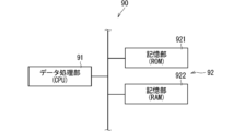
- 2 is a block diagram illustrating an example of an internal configuration of a control unit.
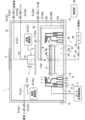
- FIG. FIG. 2 is a vertical cross-sectional view illustrating an example of the configuration of a processing unit according to the first embodiment.
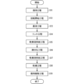
- 13 is a flowchart showing an example of an operation of a processing unit.
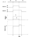
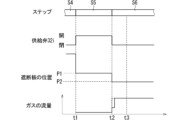
- 5A and 5B are diagrams showing an example of a timing chart of the processing unit and a schematic diagram showing an example of a change in temperature of a first main surface of a substrate over time.
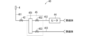
- FIG. 11 is a diagram illustrating an example of the configuration of a substrate heating unit according to a second embodiment.
- 13A to 13C are diagrams showing an example of a timing chart of a processing unit according to a second embodiment, and a schematic diagram showing an example of changes over time in the flow rate of a heat medium and the temperature of the heat medium;
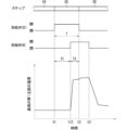
- 13A to 13C are diagrams illustrating an example of a timing chart of a processing unit according to a third embodiment and a schematic diagram illustrating an example of a temperature change of a first main surface of a substrate.
- 13A to 13C are diagrams showing an example of a timing chart of a processing unit according to a fourth embodiment, and a schematic diagram showing an example of changes over time in the flow rate of a heat medium, the temperature of the heat medium, and the temperature of a first main surface of a substrate.
- 13 is a flowchart showing a first example of an operation of the processing unit according to the fifth embodiment.
- 13 is a flowchart showing a second example of the operation of the processing unit according to the fifth embodiment.
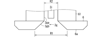
- 13A and 13B are diagrams illustrating a first example of the configuration of a blocking plate according to the sixth embodiment.
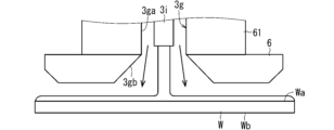
- 10A and 10B are diagrams each showing an example of a state in which an inert gas is discharged; FIG.
- FIG. 23 is a diagram showing a first example of a timing chart of a processing unit according to the sixth embodiment.
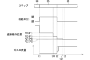
- FIG. 23 is a diagram illustrating a second example of a timing chart of the processing unit according to the sixth embodiment.
- 11A and 11B are diagrams illustrating an example of a processing unit in a drying liquid supplying step.
- 13A and 13B are diagrams illustrating an example of a processing unit in a drying liquid supplying step according to a sixth embodiment.
- 13A and 13B are diagrams illustrating a second example of the configuration of the blocking plate according to the sixth embodiment.
- an expression indicating an equal state e.g., "same,” “equal,” “homogeneous,” etc.
- the expression not only strictly indicates a state in which the quantitative relationship is equal, but also indicates a state in which a difference exists within a range in which a tolerance or similar function is obtained, unless otherwise specified.
- an expression indicating a shape e.g., "square shape” or “cylindrical shape,” etc.
- the expression not only strictly indicates the shape geometrically, but also indicates a shape having, for example, irregularities or chamfers within a range in which a similar effect is obtained, unless otherwise specified.
- the expression is not an exclusive expression that excludes the presence of other components.
- the expression includes only A, only B, only C, any two of A, B, and C, and all of A, B, and C.
- First Embodiment ⁇ Overall configuration of substrate processing apparatus> 1 is a plan view illustrating an example of the configuration of a substrate processing apparatus 100.
- the substrate processing apparatus 100 is a single-wafer processing apparatus that processes substrates W one by one.
- the substrate W is, for example, a semiconductor wafer, a substrate for a liquid crystal display, a substrate for an organic electroluminescence (EL), a substrate for a flat panel display (FPD), a substrate for an optical display, a substrate for a magnetic disk, a substrate for an optical disk, a substrate for a magneto-optical disk, a substrate for a photomask, or a substrate for a solar cell.
- the substrate W has a thin flat plate shape having a first main surface Wa and a second main surface Wb.
- the second main surface Wb is the surface opposite to the first main surface Wa.
- the substrate W is assumed to be a semiconductor wafer.
- the substrate W has, for example, a disk shape.
- the diameter of the substrate W is, for example, about 300 mm, and the thickness of the substrate W is, for example, about 0.5 mm or more and about 3 mm or less.
- a pattern is formed on the main surface of the substrate W.
- the pattern here includes, for example, at least one of a wiring pattern, an electrode pattern, a semiconductor pattern, and an insulating pattern.
- the aspect ratio of the pattern is, for example, 5 or more and 500 or less.
- the pattern width is, for example, 3 nm or more and 50 nm or less. Patterns with such high aspect ratios are prone to collapse.
- the substrate processing apparatus 100 includes an indexer block 110, a processing block 120, and a control unit 90.
- the processing block 120 is a section that mainly processes substrates W
- the indexer block 110 is a section that mainly transports substrates W between the outside of the substrate processing apparatus 100 and the processing block 120.
- the indexer block 110 includes a load port 111 and a first transport section 112.
- a substrate container (hereinafter referred to as a carrier) C that has been brought in from the outside is placed on the load port 111.
- the carrier C accommodates multiple substrates W, for example, lined up at intervals from each other in the vertical direction. In the example of FIG. 1, multiple load ports 111 are arranged.
- the first transport unit 112 is a transport robot and can remove unprocessed substrates W from carriers C placed on each load port 111.
- the first transport unit 112 can also be called an indexer robot.
- the first transport unit 112 transports the unprocessed substrates W removed from the carriers C to the processing block 120.
- the processing block 120 can process the unprocessed substrates W.
- the first transport unit 112 can also receive processed substrates W from the processing block 120 and transport the processed substrates W to the carriers C of the load port 111.
- the processing block 120 includes a plurality of processing units 1 and a second transport section 122.
- the second transport section 122 is a transport robot and can transport substrates W between the first transport section 112 and the plurality of processing units 1.
- the processing block 120 also includes a placement section 123.
- the placement section 123 is, for example, a shelf on which a plurality of substrates W can be placed in a vertically aligned state.
- the first transport section 112 places an unprocessed substrate W on the placement section 123.
- the second transport section 122 removes the unprocessed substrate W from the placement section 123 and transports the substrate W to the processing unit 1.
- the processing unit 1 processes the substrate W.
- the configuration of the processing unit 1 will be described later.
- the second transport section 122 removes the processed substrate W from the processing unit 1 and transports the substrate W to the placement section 123.
- the first transport section 112 removes the substrate W from the placement section 123 and transports the substrate W to the carrier C of the load port 111.
- multiple (e.g., four) processing units 1 are arranged to surround the second transport section 122 in a plan view.
- This second transport section 122 may also be called a center robot.
- multiple processing units 1 may be stacked vertically.
- multiple towers TW four in the figure, each of which is made up of multiple processing units 1 stacked vertically, may be arranged to surround the second transport section 122.
- the control unit 90 comprehensively controls the substrate processing apparatus 100. Specifically, the control unit 90 controls the first transport unit 112, the second transport unit 122, and the processing unit 1.
- FIG. 2 is a block diagram showing an example of the internal configuration of the control unit 90.
- the control unit 90 is an electronic circuit, and has, for example, a data processing unit 91 and a memory unit 92. In the specific example of FIG. 2, the data processing unit 91 and the memory unit 92 are connected to each other via a bus 93.
- the data processing unit 91 may be, for example, an arithmetic processing device such as a CPU (Central Processor Unit).
- the memory unit 92 may have a non-transient memory unit (for example, a ROM (Read Only Memory)) 921 and a temporary memory unit (for example, a RAM (Random Access Memory)) 922.
- the non-transient memory unit 921 may store, for example, a program that specifies the processing to be executed by the control unit 90.
- the data processing unit 91 executes this program, and the control unit 90 can execute the processing specified in the program.
- some or all of the processing performed by the control unit 90 may be performed by hardware such as a dedicated logic circuit.
- Fig. 3 is a vertical cross-sectional view that shows an example of the configuration of the processing unit 1 according to the first embodiment. It is not necessary that all processing units 1 in the substrate processing apparatus 100 have the configuration shown in Fig. 3. It is sufficient that at least one processing unit 1 in the substrate processing apparatus 100 has the configuration shown in Fig. 3.
- the processing unit 1 includes a substrate holder 2, at least one nozzle 3, and a substrate heater 40.
- the processing unit 1 is also provided with a chamber 10.
- the chamber 10 has a box-like shape, and its internal space corresponds to a processing space in which the substrate W is processed.
- the chamber 10 is provided with an openable and closable loading/unloading entrance (not shown).
- the second transport part 122 loads an unprocessed substrate W into the chamber 10 through the loading/unloading entrance, and also loads a processed substrate W out of the chamber 10 through the loading/unloading entrance.
- a fan filter unit 11 is provided on the ceiling of the chamber 10.
- the fan filter unit 11 takes in air from outside the chamber 10, purifies it, and sends the purified air into the chamber 10. Operation of the fan filter unit 11 creates a downflow of clean air within the chamber 10.
- the upstream end of an exhaust pipe 13 is connected to the lower part of the side wall of the chamber 10. Gas within the chamber 10 is exhausted to the outside through the exhaust pipe 13.
- the substrate holder 2 is provided in the chamber 10 and holds the substrate W in a horizontal position while rotating the substrate W around a rotation axis Q1.
- the horizontal position here means that the thickness direction of the substrate W is along the vertical direction.
- the rotation axis Q1 is an axis that passes through the center of the substrate W and is along the vertical direction.
- Such a substrate holder 2 may also be called a spin chuck.
- the first main surface Wa of the substrate W on which the pattern is formed faces vertically upward. That is, in the example of FIG. 3, the first main surface Wa of the substrate W held by the substrate holding part 2 corresponds to the top surface.
- the pattern includes, for example, at least one of a wiring pattern, an insulating pattern, and a semiconductor pattern.
- the substrate holding unit 2 includes a spin base 21, chuck pins 22, and a rotation drive unit 23.
- the spin base 21 has a plate-like shape (e.g., a disk shape) and is arranged with its thickness direction along the vertical direction.
- a plurality of chuck pins 22 are provided on the upper surface of the spin base 21.
- the plurality of chuck pins 22 are arranged at equal intervals along the circumferential direction about the rotation axis Q1.
- the plurality of chuck pins 22 are arranged so that they can be displaced between a holding position and a release position, which will be described next.
- the holding position is a position where the chuck pins 22 abut against the periphery of the substrate W.
- the plurality of chuck pins 22 hold the substrate W by stopping at their respective holding positions.
- FIG. 3 shows the chuck pins 22 stopped at the holding position.
- the release position is a position where each chuck pin 22 is separated from the substrate W.
- the plurality of chuck pins 22 stop at their respective release positions, and thus the holding of the substrate W by the plurality of chuck pins 22 is released.
- the substrate holder 2 also includes a pin driver (not shown) that displaces the chuck pins 22.
- the pin driver includes a drive source such as a motor and an air cylinder, and is controlled by the controller 90.
- the rotation drive unit 23 includes a shaft 231 and a motor 232.
- the upper end of the shaft 231 is connected to the underside of the spin base 21, and the shaft 231 extends from the underside of the spin base 21 along the rotation axis Q1.
- the motor 232 is controlled by the control unit 90, and rotates the shaft 231 around the rotation axis Q1. This causes the spin base 21, chuck pins 22, and substrate W to rotate together around the rotation axis Q1.
- the substrate holding unit 2 does not necessarily have to have a chuck pin 22.
- the substrate holding unit 2 may hold the substrate W using a chuck method such as a vacuum chuck, an electrostatic chuck, or a Bernoulli chuck.
- At least one nozzle 3 ejects liquid toward a first main surface Wa of the substrate W held by the substrate holding part 2.
- the first main surface Wa is the upper surface, so the nozzle 3 is provided vertically above the substrate W held by the substrate holding part 2.
- nozzles 3c, 3w, and 3i are provided as nozzles 3.
- Nozzle 3c ejects the chemical liquid
- nozzle 3w ejects the rinsing liquid
- nozzle 3i ejects the drying liquid.
- Specific examples of the chemical liquid, rinsing liquid, and drying liquid will be described later.
- the chemical liquid, rinsing liquid, and drying liquid are also collectively referred to as the processing liquid.
- Nozzle 3 is, for example, a straight nozzle that ejects the processing liquid in a continuous flow.
- the nozzle 3 is movable by the movement drive unit 35.
- the movement drive unit 35 includes the movement drive unit 35c, the movement drive unit 35w, and the movement drive unit 35i.
- the movement drive unit 35c moves the nozzle 3c
- the movement drive unit 35w moves the nozzle 3w
- the movement drive unit 35i moves the nozzle 3i.
- the movement driver 35c moves the nozzle 3c between a first processing position and a first waiting position, which will be described below.
- the first waiting position is a position where the nozzle 3c does not eject the chemical liquid toward the first main surface Wa of the substrate W, and is, for example, a position radially outward from the substrate holder 2.
- the example in FIG. 3 shows the nozzle 3c stopped at the first waiting position.
- the first processing position is a position where the nozzle 3c ejects the chemical liquid toward the first main surface Wa of the substrate W, and is, for example, a position vertically opposite the center of the first main surface Wa of the substrate W.
- the movement driver 35w moves the nozzle 3w between a second processing position and a second waiting position, which will be described next.
- the second processing position is a position where the nozzle 3w ejects the rinsing liquid toward the first main surface Wa of the substrate W, for example, a position vertically opposite the center of the first main surface Wa of the substrate W.
- the example in FIG. 3 shows the nozzle 3w stopped at the second processing position.
- the second waiting position is a position where the nozzle 3w does not eject the rinsing liquid toward the first main surface Wa of the substrate W, for example, a position radially outward from the substrate holder 2.
- the moving drive unit 35w includes an arm 351, a support column 352, and a drive source 353.
- the support column 352 is provided radially outward from the guard 7 described below and extends along the vertical direction.
- the arm 351 extends along the horizontal direction, its tip connected to the nozzle 3w, and its base connected to the support column 352.
- the drive source 353 is controlled by the control unit 90 and rotates the support column 352 in forward and reverse directions within a predetermined angle range around its central axis Q2.
- the drive source 353 includes, for example, a motor.
- the nozzle 3w reciprocates along the circumferential direction about the central axis Q2.
- the support column 352 is installed so that the second processing position and the second standby position are located on the movement trajectory of the nozzle 3w.
- the movement drive unit 35w is not necessarily limited to the embodiment shown in FIG. 3, and may include, for example, a linear motion mechanism such as a linear motor.
- the movement drive unit 35c may have, for example, a configuration similar to that of the movement drive unit 35w.
- the movement drive unit 35i moves the nozzle 3i between the blocking processing position and the blocking standby position, which will be described next.
- the nozzle 3i is provided integrally with the blocking plate 6, which will be described later, and the movement drive unit 35i moves the nozzle 3i and the blocking plate 6 together.
- the blocking processing position is a position where the nozzle 3i ejects the drying liquid toward the first main surface Wa of the substrate W, and is, for example, a position vertically opposite the center of the first main surface Wa of the substrate W.
- the blocking standby position is a position where the nozzle 3i does not eject the drying liquid toward the first main surface Wa of the substrate W, and is, for example, a position vertically above the blocking processing position. In the example of FIG.
- the movement drive unit 35i moves the nozzle 3i along the vertical direction, so it can also be said to be an elevation drive unit.
- the movement drive unit 35i includes a drive source such as a motor and a power transmission unit that transmits power from the drive source to the nozzle 3i and the blocking plate 6.
- the power transmission unit includes, for example, a cam mechanism or a ball screw mechanism.
- the nozzle 3 is connected to the downstream end of the supply pipe 31, and the upstream end of the supply pipe 31 is connected to a processing liquid supply source.
- supply pipes 31c, 31w, and 31i are shown as the supply pipe 31.
- the downstream end of the supply pipe 31c is connected to the nozzle 3c, and the upstream end of the supply pipe 31c is connected to a chemical supply source.
- the chemical supply source has a tank (not shown) for storing the chemical liquid, and supplies the chemical liquid to the upstream end of the supply pipe 31c.
- a hydrofluoric nitric acid solution obtained by mixing hydrofluoric acid, nitric acid, and water
- a hydrofluoric acid hydrogen peroxide solution (FPM) obtained by mixing hydrofluoric acid, hydrogen peroxide, and water
- TMAH tetramethylammonium hydroxide
- SPM sulfuric acid and hydrogen peroxide
- ammonia water a mixture of ammonia, hydrogen peroxide, and water
- SC-1 mixture of ammonia, hydrogen peroxide, and water
- SC-2 a mixture of hydrogen chloride, hydrogen peroxide, and water
- SC-2 a mixture of hydrogen chloride, hydrogen peroxide, and water
- the downstream end of the supply pipe 31w is connected to the nozzle 3w, and the upstream end of the supply pipe 31w is connected to a rinse liquid supply source.
- the rinse liquid supply source has a tank (not shown) that stores the rinse liquid, and supplies the rinse liquid to the upstream end of the supply pipe 31w.
- pure water, carbon dioxide water, or ozone water can be used as the rinse liquid.
- the downstream end of the supply pipe 31i is connected to the nozzle 3i, and the upstream end of the supply pipe 31i is connected to a drying liquid supply source.
- the drying liquid supply source has a tank (not shown) that stores drying liquid, and supplies drying liquid to the upstream end of the supply pipe 31i.
- the drying liquid for example, an organic solvent such as isopropyl alcohol can be used.
- the surface tension of the drying liquid is lower than the surface tension of other processing liquids (for example, both the surface tension of the chemical liquid and the surface tension of the rinse liquid).
- the volatility of the drying liquid is higher than the volatility of other processing liquids (for example, both the volatility of the chemical liquid and the volatility of the rinse liquid).
- a supply valve 32 and a flow rate adjustment valve 33 are inserted in the supply pipe 31.
- a supply valve 32c and a flow rate adjustment valve 33c are inserted in the supply pipe 31c
- a supply valve 32w and a flow rate adjustment valve 33w are inserted in the supply pipe 31w
- a supply valve 32i and a flow rate adjustment valve 33i are inserted in the supply pipe 31i.
- the supply valve 32 switches the supply pipe 31 between open and closed.
- the flow rate adjustment valve 33 adjusts the flow rate of the processing liquid flowing through the supply pipe 31.
- the flow rate adjustment valve 33 may be a mass flow controller.
- the supply valve 32 and the flow rate adjustment valve 33 are controlled by the control unit 90.
- the supply valve 32 opens and a processing liquid is ejected from the nozzle 3 toward the first main surface Wa of the rotating substrate W.
- the processing liquid that has landed on the first main surface Wa of the substrate W is subjected to centrifugal force accompanying the rotation of the substrate W, and flows radially outward along the first main surface Wa, and is splashed outward from the periphery of the substrate W.
- This allows processing according to the type of processing liquid to be performed on the first main surface Wa of the substrate W. For example, when a cleaning chemical liquid is ejected, the first main surface Wa of the substrate W is cleaned by the chemical liquid.
- the substrate heating unit 40 heats the second main surface Wb of the substrate W held by the substrate holding unit 2.
- the substrate heating unit 40 is provided at a position vertically opposite the second main surface Wb of the substrate W.
- the second main surface Wb of the substrate W corresponds to the bottom surface, so the substrate heating unit 40 is provided directly below the substrate W.
- the substrate heating unit 40 includes a nozzle 4.
- the nozzle 4 ejects a heat medium toward the second main surface Wb of the substrate W.
- the second main surface Wb of the substrate W corresponds to the bottom surface, so the nozzle 4 may also be called a bottom nozzle.
- a through hole is formed in the center of the spin base 21 of the substrate holding unit 2, and the shaft 231 is a hollow shaft. The through hole of the spin base 21 and the hollow part of the shaft 231 are connected in the vertical direction. A part of the nozzle 4 is disposed in the through hole.
- An ejection port is formed in the upper surface of the nozzle 4, and the ejection port of the nozzle 4 faces the center of the second main surface Wb of the substrate W in the vertical direction.
- the nozzle 4 ejects a heat medium toward the center of the second main surface Wb of the substrate W.
- the downstream end of the supply pipe 41 is connected to the nozzle 4.
- the supply pipe 41 extends inside the shaft 231 and penetrates the shaft 231.
- the upstream end of the supply pipe 41 is connected to a heat medium supply source.
- the heat medium is a fluid (gas or liquid), and a more specific example is a liquid such as water.
- the heat medium supply source has, for example, a tank (not shown) that stores the heat medium, and supplies the heat medium to the upstream end of the supply pipe 41.
- the supply pipe 41 is provided with a supply valve 42, a flow rate adjustment valve 43, and a heater 44.
- the supply valve 42 switches the supply pipe 41 between open and closed states.
- the flow rate adjustment valve 43 adjusts the flow rate of the heat medium flowing through the supply pipe 41.
- the flow rate adjustment valve 43 may be a mass flow controller.
- the heater 44 heats the heat medium flowing through the supply pipe 41.
- the heater 44 may be, for example, an electric resistance heater having a heating wire.
- the supply valve 42, the flow rate adjustment valve 43, and the heater 44 are controlled by the control unit 90.
- a high-temperature heat medium is discharged from the nozzle 4 onto the center of the second main surface Wb of the rotating substrate W.
- the heat medium that has landed on the center of the second main surface Wb of the substrate W is subjected to centrifugal force accompanying the rotation of the substrate W, and flows radially outward along the second main surface Wb, and is scattered outward from the periphery of the substrate W.
- the high-temperature heat medium flows along the second main surface Wb of the substrate W, heat is transferred from the heat medium to the substrate W, and the substrate W is heated.
- the processing unit 1 is provided with a guard 7 and a guard lifting drive 71.
- the guard 7 has a cylindrical shape with the rotation axis Q1 as its central axis, and surrounds the substrate holder 2.
- the guard 7 can receive the processing liquid and heat medium splashed from the periphery of the substrate W.
- the guard lifting drive 71 raises and lowers the guard 7 between an upper position and a lower position, which will be described below.
- the upper position is a position where the upper end of the guard 7 is vertically above the substrate W held by the substrate holder 2. When the guard 7 is in the upper position, it can receive the processing liquid and heat medium splashed from the periphery of the substrate W.
- the lower position is a position lower than the upper position, for example, a position where the upper end of the guard 7 is vertically below the upper surface of the spin base 21.
- the diameter of the shield plate 6 (i.e., the diameter of the opposing surface) may be, for example, 80% or more of the diameter of the substrate W, 90% or more, or may be equal to or greater than the diameter of the substrate W.
- a through hole is formed in the center of the shield plate 6, penetrating the shield plate 6 in the vertical direction, and the nozzle 3i is provided inside the through hole.
- a hollow shaft 61 is provided on the upper surface of the blocking plate 6.
- the hollow shaft 61 has a hollow portion, which is connected vertically to the through hole of the blocking plate 6.
- the diameter of the outer peripheral surface of the nozzle 3i is smaller than the diameters of the hollow shaft 61 and the inner peripheral surfaces of the blocking plate 6.
- the space between the outer peripheral surface of the nozzle 3i and the hollow shaft 61 and the inner peripheral surface of the blocking plate 6 functions as a gas flow path 3g, as described below.
- the upper part of the hollow shaft 61 is connected to the downstream end of the supply pipe 31g.
- the downstream end of the supply pipe 31g is connected to the gas flow path 3g between the outer peripheral surface of the nozzle 3i and the inner peripheral surfaces of the hollow shaft 61 and the blocking plate 6.
- the upstream end of the supply pipe 31g is connected to a gas supply source.
- the gas supply source has a storage section (not shown) for storing an inert gas, and supplies the inert gas to the upstream end of the supply pipe 31g.
- the inert gas includes, for example, at least one of nitrogen gas and a rare gas.
- the rare gas includes, for example, argon gas.
- the supply pipe 31g is provided with a supply valve 32g, a flow rate adjustment valve 33g, and a heater 34g.
- the supply valve 32g switches the supply pipe 31g between open and closed states.
- the flow rate adjustment valve 33g adjusts the flow rate of the inert gas flowing through the supply pipe 31g.
- the heater 34g heats the inert gas flowing through the supply pipe 31g.
- the heater 34g may be, for example, an electric resistance heater having a heating wire.
- the supply valve 32g, the flow rate adjustment valve 33g, and the heater 34g are controlled by the control unit 90.
- Fig. 4 is a flow chart showing an example of the operation of the processing unit 1.
- the control unit 90 causes the processing unit 1 to execute the processes from step S1 to step S7 according to a preset processing procedure (recipe).
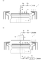
- Figs. 5 and 6 are diagrams each showing an outline of an example of the state of the processing unit 1 at each step.
- the second transport unit 122 transports the substrate W to the processing unit 1.
- the substrate holding unit 2 holds the substrate W received from the second transport unit 122 (step S1: holding process).
- the substrate holding unit 2 displaces the multiple chuck pins 22 from their respective release positions to their holding positions.
- the multiple chuck pins 22 hold the substrate W.
- the substrate holding unit 2 continues to hold the substrate W until processing of the substrate W is completed.
- step S2 rotation start step
- the substrate holder 2 may continue rotating the substrate W until processing of the substrate W is completed.
- step S3 chemical liquid process
- the movement drive unit 35c moves the nozzle 3c to the first processing position.
- the guard lift drive unit 71 raises the chemical liquid guard 7 to the upper position.
- the control unit 90 opens the supply valve 32c. That is, the control unit 90 switches the supply valve 32c from a closed state to an open state. This causes the chemical liquid to be discharged from the nozzle 3c toward the first main surface Wa of the substrate W during rotation.
- the chemical liquid that has landed on the first main surface Wa of the substrate W flows radially outward due to the centrifugal force associated with the rotation of the substrate W, and is scattered from the periphery of the substrate W.
- the chemical liquid acts on the first main surface Wa of the substrate W, and a chemical liquid process according to the type of chemical liquid is performed on the first main surface Wa of the substrate W.
- the processing unit 1 performs a cleaning process for cleaning and removing impurities on the first main surface Wa of the substrate W, or an etching process for etching a predetermined film on the first main surface Wa of the substrate W.
- Chemical liquid that splashes from the edge of the substrate W is received by the guard 7 and discharged to the outside of the chamber 10 through the discharge pipe 12.
- the control unit 90 closes the supply valve 32c.
- the control unit 90 measures the time that has elapsed since the start of the discharge of the chemical liquid, and determines whether the elapsed time is equal to or greater than a predetermined chemical liquid time.
- the chemical liquid time is set in advance to a time that will allow sufficient chemical liquid processing.
- the elapsed time is measured, for example, by a timer circuit (not shown) that belongs to the control unit 90.
- the control unit 90 switches the supply valve 32c from an open state to a closed state. Furthermore, after closing the supply valve 32c, the movement drive unit 35c moves the nozzle 3c to the first standby position.
- the processing unit 1 supplies the rinse liquid to the first main surface Wa of the substrate W (step S4: rinse process). Specifically, first, the movement drive unit 35w moves the nozzle 3w to the second processing position. Also, if the guard 7 for the rinse liquid is different from the guard 7 for the chemical liquid, the guard lift drive unit 71 appropriately lifts and lowers the guard 7 to position the guard 7 for the rinse liquid at the upper position. Then, the control unit 90 opens the supply valve 32w. That is, the control unit 90 switches the supply valve 32w from a closed state to an open state. As a result, as shown in FIG. 5(a), the rinse liquid is discharged from the nozzle 3w toward the first main surface Wa of the substrate W during rotation.
- the rinse liquid that has landed on the first main surface Wa of the substrate W flows radially outward due to the centrifugal force accompanying the rotation of the substrate W, and is scattered from the periphery of the substrate W. At this time, the rinse liquid pushes the chemical liquid on the first main surface Wa of the substrate W radially outward. As a result, the processing liquid on the first main surface Wa of the substrate W is replaced from the chemical liquid to the rinsing liquid. Processing liquid that has splashed from the periphery of the substrate W is received by the guard 7 and discharged to the outside of the chamber 10 through the discharge pipe 12.
- the control unit 90 closes the supply valve 32w.
- the control unit 90 measures the elapsed time from the start of ejection of the rinsing liquid, and switches the supply valve 32w from an open state to a closed state when the elapsed time is equal to or greater than a predetermined rinsing time.
- the rinsing time is preset to a time that will allow the chemical liquid to be sufficiently replaced with the rinsing liquid.
- the processing unit 1 supplies drying liquid to the first main surface Wa of the substrate W (step S5: drying liquid supply process). Specifically, first, the movement drive unit 35i moves the nozzle 3i and the blocking plate 6 together to the blocking processing position. Furthermore, if the guard 7 for the drying liquid is different from the guard 7 for the rinsing liquid, the guard lift drive unit 71 lifts and lowers the guard 7 appropriately to raise the guard 7 for the drying liquid to the upper position. Then, the control unit 90 opens the supply valve 32i. In other words, the control unit 90 switches the supply valve 32i from a closed state to an open state.
- the drying liquid is discharged from the nozzle 3i toward the first main surface Wa of the rotating substrate W.
- the temperature of the drying liquid may be, for example, room temperature (for example, about 25 degrees Celsius).
- the drying liquid that has landed on the first main surface Wa of the substrate W flows radially outward due to the centrifugal force accompanying the rotation of the substrate W, and splashes from the periphery of the substrate W.
- the drying liquid pushes away the rinsing liquid on the first main surface Wa of the substrate W, so that the processing liquid on the first main surface Wa of the substrate W is replaced from the rinsing liquid to the drying liquid.
- the processing liquid that has splashed from the periphery of the substrate W is received by the guard 7 and discharged to the outside of the chamber 10 through the discharge pipe 12.
- the rotation speed of the substrate W in the drying liquid supply process may be set, for example, to 150 rpm or more and 600 rpm or less, or 200 rpm or more and 400 rpm or less. As a more specific example, the rotation speed can be set to 300 rpm.
- the processing unit 1 may also heat the substrate W when the drying liquid is supplied. That is, the substrate heating section 40 may heat the second main surface Wb of the substrate W.
- the control section 90 may open the supply valve 42 and operate the heater 44.
- a high-temperature heat medium e.g., hot water
- the heater 44 may heat the temperature of the heat medium to, for example, 60 degrees Celsius or more, 70 degrees Celsius or more, or 80 degrees Celsius or more.
- the heater 44 may also adjust the temperature of the heat medium to, for example, less than the boiling point of the drying liquid.
- the temperature of the heat medium here is, for example, the temperature of the heat medium at the discharge port of the nozzle 4.
- the flow rate control valve 43 may adjust the flow rate of the heat medium to, for example, a value greater than the flow rate of the drying liquid. More specifically, the flow rate control valve 43 may adjust the flow rate of the heat medium to 1000 mL (milliliters)/min or more, or to 1500 mL/min or more.
- the heat medium that has landed in the center of the second main surface Wb of the substrate W flows radially outward due to the centrifugal force caused by the rotation of the substrate W, and is scattered from the periphery of the substrate W.
- heat is transferred from the heat medium to the substrate W, heating the substrate W.
- the heat of the substrate W is transferred to the drying liquid on the first main surface Wa.
- the drying liquid on the first main surface Wa of the substrate W is also heated and rises in temperature.
- the processing unit 1 dries the substrate W (step S6: drying process). Specifically, the processing unit 1 measures the elapsed time from the start of the ejection of the drying liquid, and judges whether the elapsed time is equal to or longer than a predetermined drying liquid supply time.
- the drying liquid supply time is set in advance to a time sufficient for the rinsing liquid to be sufficiently replaced with the drying liquid.
- the drying liquid supply time is set, for example, to about several tens of seconds, and specifically, may be set to about 40 seconds. Then, when the elapsed time is equal to or longer than the drying liquid supply time, the processing unit 1 dries the substrate W.
- control unit 90 closes the supply valve 32i, opens the supply valve 32g, operates the heater 34g, causes the moving drive unit 35i to lower the blocking plate 6 to a drying position closer to the substrate W than the blocking processing position, and causes the substrate holder 2 to increase the rotation speed of the substrate W.
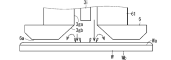
- the supply valve 32g opens, as shown in FIG. 6(a), high-temperature inert gas is discharged from a gas outlet in the center of the lower surface of the blocking plate 6 (i.e., the lower end port of the gas flow path 3g) toward the first main surface Wa of the substrate W.
- the flow direction of the inert gas is shown diagrammatically by an arrow directly below the blocking plate 6.
- the heater 34g may heat the inert gas to, for example, 60 degrees Celsius or higher, 70 degrees Celsius or higher, or 80 degrees Celsius or higher.
- the temperature of the inert gas may be, for example, the temperature of the inert gas at the gas outlet of the gas flow path 3g.
- the flow rate adjustment valve 33g may adjust the flow rate of the inert gas to, for example, 10 L (liters)/min or more and 300 L/min or less.
- the blocking plate 6 is shown descending as a block arrow next to the blocking plate 6.
- the movement drive unit 35i lowers the nozzle 3i and the blocking plate 6 together while the inert gas is being discharged from the gas flow path 3g.
- the gap between the blocking plate 6 and the first main surface Wa of the substrate W can be narrowed as shown in FIG. 6(b). That is, the gap between the blocking plate 6 and the substrate W in the drying process can be narrower than the gap between the blocking plate 6 and the substrate W in the drying liquid supply process. Therefore, in the drying process, the flow rate of the inert gas flowing outward in the radial direction from the periphery of the blocking plate 6 and the substrate W can be increased.
- the gap between the lower surface of the blocking plate 6 and the first main surface Wa of the substrate W is set to, for example, about several mm (for example, 5 mm) or less.
- the substrate holding unit 2 may increase the rotational speed of the substrate W monotonically and non-decreasingly without reducing it during the transition from the drying liquid supply process to the drying process and at the beginning of the drying process.
- the substrate holding unit 2 may rotate the substrate W at a rotational speed of, for example, 800 rpm or more and 2500 rpm or less, or may rotate the substrate W at a rotational speed of 800 rpm or more and 1500 rpm or less.
- the substrate holding unit 2 may also gradually (for example, stepwise) increase the rotational speed of the substrate W during or after the lowering of the blocking plate 6.
- the amount of drying liquid that splashes off from the periphery of the substrate W can be increased. This allows the drying liquid to evaporate while keeping the film of drying liquid on the first main surface Wa thin. This allows the drying liquid to evaporate in a shorter time.
- the inert gas flows out radially outward from between the shielding plate 6 and the substrate W at a high flow rate. This allows the inert gas to push the heat medium back radially outward. This makes it possible to suppress or prevent the heat medium from flowing around.
- the distance between the shielding plate 6 and the substrate W and the flow rate of the inert gas can be set to a level that sufficiently suppresses the heat medium from flowing around.
- the substrate heating unit 40 stops heating the substrate W.
- the control unit 90 measures the time that has elapsed since the drying liquid was stopped being discharged, and determines whether the measured time is equal to or longer than a predetermined evaporation time.
- the evaporation time is set in advance to a time that will allow the first main surface Wa of the substrate W to be sufficiently dried.
- the control unit 90 switches the supply valve 42 from an open state to a closed state. This stops the supply of heat medium to the second main surface Wb of the substrate W. In other words, heating of the substrate W by the substrate heating unit 40 stops.
- control unit 90 stops the rotation of the substrate W, for example, when a predetermined drying time sufficient for the second main surface Wb of the substrate W to dry has elapsed.
- the movement drive unit 35i raises the nozzle 3i and the blocking plate 6 together to the blocking standby position, and the guard lift drive unit 71 lowers the guard 7 to the lower position.
- step S7 holding release process.
- the second transport unit 122 transports the processed substrate W out of the processing unit 1.
- the processing unit 1 can process the substrate W. Moreover, in this embodiment, after the supply of drying liquid is stopped, the substrate heating section 40 heats the second main surface Wb of the substrate W (drying process, FIG. 6). Therefore, in the drying process, the drying liquid on the first main surface Wa of the substrate W can evaporate at a higher temperature.
- FIG. 7 is a schematic diagram showing an example of a timing chart of the processing unit 1 and a change in temperature (hereinafter referred to as substrate temperature) over time of the first main surface Wa of the substrate W.
- the control unit 90 switches the supply valve 32i and the supply valve 42 from a closed state to an open state. Therefore, at time t1, the nozzle 3i starts to eject the drying liquid, and the nozzle 4 starts to eject the high-temperature heat medium.
- This ejection of the drying liquid essentially starts the drying liquid supply process (step S5).
- the ejection of the heat medium causes the substrate temperature of the first main surface Wa of the substrate W to rise over time. The substrate temperature rises at a high rate of increase to a certain extent, and then rises slowly or may converge.
- the control unit 90 switches the supply valve 32i from an open state to a closed state.
- the discharge of the drying liquid stops at time t2. This cessation of the discharge of the drying liquid essentially ends the drying liquid supply process.
- the supply valve 42 continues to be open even after time t2. Therefore, during the evaporation time after time t2 (the time from time t2 to time t3 in FIG. 7, which corresponds to a predetermined period), the nozzle 4 discharges the heat medium, and the substrate W continues to receive heat from the heat medium. Therefore, the substrate temperature of the first main surface Wa of the substrate W during the evaporation time can be made higher than the substrate temperature when the drying liquid is supplied. In the example of FIG. 7, the temperature of the first main surface Wa of the substrate W increases after time t2. This is because no new drying liquid is supplied to the first main surface Wa of the substrate W after time t2.
- the drying liquid which is lower in temperature than the heat medium, is supplied to the first main surface Wa of the substrate W, the drying liquid cools the substrate W, but since the supply of the drying liquid has ended after time t2, the temperature of the substrate W increases. Therefore, the substrate temperature of the first main surface Wa of the substrate W during the evaporation time is higher than the substrate temperature of the first main surface Wa of the substrate W in the drying liquid supply process.
- the temperature of the first main surface Wa of the substrate W can be considered to be approximately equal to the temperature of the drying liquid on the first main surface Wa, so the temperature of the drying liquid during the evaporation time is also higher than the temperature of the drying liquid during the drying liquid supplying process. Furthermore, the higher the temperature of the drying liquid, the lower the surface tension of the drying liquid. As described above, since the temperature of the drying liquid during the evaporation time is high, it is possible to reduce the surface tension of the drying liquid during the evaporation time. Moreover, it is also possible to improve the evaporation rate of the drying liquid.
- the control unit 90 switches the supply valve 42 from an open state to a closed state.
- the nozzle 4 stops ejecting the heat medium.
- the substrate heating unit 40 stops heating the second main surface Wb of the substrate W at time t3. Therefore, after time t3, the temperature of the first main surface Wa of the substrate W decreases over time.
- a high-temperature inert gas is supplied to the first main surface Wa of the substrate W.
- the temperature distribution of the drying liquid on the first main surface Wa of the substrate W can be made uniform.
- the substrate holder 2 increases the rotation speed of the substrate W. This makes it possible to increase the amount of drying liquid that splashes outward from the periphery of the substrate W, while further promoting evaporation of the drying liquid. In other words, the evaporation of the drying liquid is promoted while the liquid film on the first main surface Wa is thinned by the splashing. This makes it possible to further reduce the rate of pattern collapse.
- the movement driver 35i moves the shielding plate 6 to a drying position closer to the first main surface Wa than the shielding processing position. This makes it possible to narrow the gap between the shielding plate 6 and the substrate W, and to increase the flow rate of the inert gas flowing outward in the radial direction from between the shielding plate 6 and the substrate W. This makes it possible to suppress or prevent the heat medium from flowing around the periphery of the substrate W. This makes it possible to reduce the rate of pattern collapse in the periphery of the first main surface Wa of the substrate W, and also to suppress the adhesion of particles to the periphery.
- the shield plate 6 stops at the shielding processing position, which is farther from the substrate W than the drying position. Therefore, even if the drying liquid ejected from the nozzle 3i bounces off the first main surface Wa of the substrate W, the possibility of the rebounded drying liquid adhering to the underside of the shield plate 6 can be reduced. If the drying liquid adheres to the underside of the shield plate 6, for example, when the next substrate W is processed, droplets of the adhering drying liquid may fall onto the first main surface Wa of the substrate W. This is undesirable as it may cause processing problems. If the shield plate 6 stops at the shielding processing position in the drying liquid supply process as described above, the occurrence of such problems can be suppressed.
- the substrate heating section 40 heats the second main surface Wb of the substrate W during the drying liquid supplying process, and also heats the second main surface Wb of the substrate W during the transition from the drying liquid supplying process to the drying process. In other words, the substrate heating section 40 continues to heat the second main surface Wb of the substrate W throughout the drying liquid supplying process and the early stages of the drying process.
- This makes it possible to maintain a higher temperature of the first main surface Wa of the substrate W at the start of the drying process (i.e., time t2).
- time t2 the start of the drying process. Therefore, it is possible to increase the temperature of the drying liquid from the start of the drying process. Therefore, the evaporation rate of the drying liquid can be increased more quickly during the drying process, and the pattern collapse rate can be more appropriately reduced.
- the efficiency of replacing the rinsing liquid with the drying liquid can be improved by increasing the temperature of the drying liquid on the first main surface Wa of the substrate W.
- FIG. 8 is a diagram that shows an example of the configuration of the substrate heating section 40 according to the second embodiment.
- the substrate heating section 40 includes a nozzle 4, a common pipe 411, a first temperature pipe 412, a second temperature pipe 413, and a mixing section 45.
- the downstream end of the common pipe 411 is connected to the nozzle 4, and the upstream end of the common pipe 411 is connected to the mixing section 45.
- the downstream end of the first temperature pipe 412 and the downstream end of the second temperature pipe 413 are also connected to the mixing section 45.
- the upstream ends of the first temperature pipe 412 and the second temperature pipe 413 are connected to a heat medium supply source.
- a heat medium having a first medium temperature flows through the first temperature pipe 412
- a heat medium having a second medium temperature flows through the second temperature pipe 413.
- the second medium temperature is lower than the first medium temperature.
- the heat medium at the first medium temperature flowing through the first temperature pipe 412 is also referred to as the high-temperature heat medium
- the heat medium at the second medium temperature flowing through the second temperature pipe 413 is also referred to as the low-temperature heat medium.
- a heater 44 is provided in the first temperature pipe 412.
- the heater 44 heats the high-temperature heat medium flowing through the first temperature pipe 412 so that the temperature of the heat medium becomes the first medium temperature.
- the second medium temperature may be room temperature.
- a heater (not shown) may be provided in the second temperature pipe 413 to heat the low-temperature heat medium to a second medium temperature higher than room temperature.
- the mixing section 45 mixes the high-temperature heat medium from the first temperature pipe 412 and the low-temperature heat medium from the second temperature pipe 413 at a variable mixing ratio, and allows the mixed heat medium to flow into the common pipe 411.
- the mixing ratio of the mixing section 45 is controlled by the control section 90.
- the mixing section 45 includes a multiple valve 451, a flow control valve 452, and a flow control valve 453.
- the flow control valve 452 adjusts the flow rate of the high-temperature heat medium flowing through the first temperature pipe 412.
- the flow control valve 453 adjusts the flow rate of the low-temperature heat medium flowing through the second temperature pipe 413.
- the flow control valve 452 and the flow control valve 453 are controlled by the control section 90.
- the control section 90 can adjust the mixing ratio by adjusting each flow rate.
- the multiple valve 451 switches between connection and disconnection between the common pipe 411 and the first temperature pipe 412, and switches between connection and disconnection between the common pipe 411 and the second temperature pipe 413. If the multiple valve 451 itself has the function of adjusting the flow rate, the flow rate adjustment valve 452 and the flow rate adjustment valve 453 are not necessary.
- a supply valve 42 is provided in the common pipe 411.
- the supply valve 42 switches the common pipe 411 between open and closed states.
- the supply valve 42 is controlled by the control unit 90.
- the operation of the processing unit 1 according to the second embodiment is as shown in FIG. 4 referred to in the first embodiment.
- the specific operation of the substrate heating section 40 is different from that of the first embodiment.
- the substrate heating section 40 heats the substrate W in the drying step (step S6) with a second amount of heat per unit time that is greater than the first amount of heat per unit time in the drying liquid supply step (step S5).
- the substrate heating section 40 supplies the substrate W in the drying step with a heat medium having a higher temperature than the heat medium supplied to the substrate W in the drying liquid supply step.
- the substrate heating section 40 adjusts the mixture ratio of the high-temperature heat medium and the low-temperature heat medium, and supplies the heat medium having a higher temperature than the heat medium in the drying liquid supply step to the second main surface of the substrate W in the drying step.
- FIG. 9 is a diagram showing a timing chart of the processing unit 1 according to the second embodiment, and an example of the flow rate of the heat medium and the change in temperature of the heat medium over time.
- an example of the flow rate of the high-temperature heat medium is shown in graph G1
- an example of the flow rate of the low-temperature heat medium is shown in graph G2.
- the flow rate of the high-temperature heat medium is constant during the period from time t1 to time t3.
- the flow rate of the low-temperature heat medium decreases at time t2.
- the flow rate of the low-temperature heat medium during the evaporation time from time t2 to time t3 is smaller than the flow rate of the low-temperature heat medium during the drying liquid supply process from time t1 to time t2.
- the temperature of the heat medium discharged from nozzle 4 during the evaporation time is higher than the temperature of the heat medium discharged from nozzle 4 during the drying liquid supply process.
- the temperature of the heat medium discharged from the nozzle 4 in the drying liquid supply process may be adjusted to be less than the boiling point bp of the drying liquid.
- the drying liquid is isopropyl alcohol
- the boiling point bp of the drying liquid is about 82.4 degrees Celsius.
- the temperature of the heat medium in the drying liquid supply process may be adjusted to be less than 82.4 degrees Celsius.
- the first medium temperature of the high-temperature heat medium is set to a value greater than the boiling point bp of the drying liquid (e.g., 85 degrees Celsius)
- the second medium temperature of the low-temperature heat medium is set to a value less than the boiling point pb of the drying liquid (e.g., room temperature).
- the mixer 45 mixes the high-temperature heat medium and the low-temperature heat medium at a mixing ratio such that the temperature of the heat medium is less than the boiling point bp of the drying liquid.
- the drying liquid on the first main surface Wa of the substrate W is also below the boiling point bp. This makes it possible to more reliably prevent the drying liquid on the first main surface Wa of the substrate W from boiling while the drying liquid is being supplied. If the drying liquid on the first main surface Wa of the substrate W boils while the drying liquid is being supplied, many particles will adhere to the first main surface Wa of the substrate W. In this embodiment, the adhesion of such particles can be more reliably prevented.
- substrate heating section 40 may adjust the temperature of the heat medium during the evaporation time from time t2 to time t3 to be equal to or higher than the boiling point bp of the drying liquid.
- mixer 45 may adopt a mixing ratio that makes the temperature of the heat medium equal to or higher than the boiling point bp of the drying liquid. In the example of FIG. 9, the flow rate of the low-temperature heat medium is set to zero.
- the mixing unit 45 may gradually change the mixing ratio over time. For example, the mixing unit 45 may gradually change the mixing ratio during the time when the blocking plate 6 is descending from the blocking processing position to the drying position.
- the temperature of the heat medium in the drying process is higher than the temperature of the heat medium in the drying liquid supplying process. This makes it possible to further increase the temperatures of the substrate W and the drying liquid in the drying process. This therefore makes it possible to further improve the evaporation rate of the drying liquid in the drying process. This makes it possible to further reduce the rate of collapse of the pattern on the substrate W.
- the temperature of the substrate W and the drying liquid in the drying liquid supplying process can be made lower than in the drying process. This makes it possible to suppress or prevent the drying liquid from boiling on the first main surface Wa of the substrate W in the drying liquid supplying process, and to suppress adhesion of particles to the first main surface Wa.
- the substrate heating section 40 changes the temperature of the heat medium discharged from the nozzle 4 by changing the mixing ratio in the mixing section 45. This allows the temperature of the heat medium to be changed quickly. Therefore, in the early stage of the drying process, the temperature of the heat medium can be increased more quickly, and the evaporation rate of the drying liquid can be increased more quickly. This also makes it possible to further reduce the rate of pattern collapse.
- the substrate heating unit 40 starts heating the second main surface Wb of the substrate W at approximately the same time as the nozzle 3i starts to discharge the drying liquid in the drying liquid supplying step (step S5) (see FIGS. 7 and 9).
- the substrate heating unit 40 may start heating the second main surface Wb of the substrate W at a time later than the nozzle 3i starts to discharge the drying liquid.
- FIG. 10 is a diagram showing a timing chart of the processing unit 1 according to the third embodiment and an example of a temperature change of the first main surface Wa of the substrate W.
- the control unit 90 switches the supply valve 32i from a closed state to an open state at time t1.
- the drying liquid starts to be discharged from the nozzle 3i toward the first main surface Wa of the substrate W. That is, the drying liquid supply process essentially starts at time t1.
- the control unit 90 switches the supply valve 42 from a closed state to an open state at time t12 after time t1.
- the high-temperature heat medium starts to be discharged from the nozzle 4 toward the second main surface Wb of the substrate W.
- the substrate heating unit 40 starts to heat the second main surface Wb of the substrate W.
- the control unit 90 switches the supply valve 32i from an open state to a closed state at time t2 after time t12. That is, the drying liquid supply process essentially ends at time t2.
- the substrate heating unit 40 does not heat the second main surface Wb of the substrate W during a predetermined pre-time T1 from time t1 to time t12, but heats the second main surface Wb of the substrate W during a predetermined post-time T2 from time t12 to time t2.
- the drying liquid supply time T is set to, for example, 20 seconds or more, and as a specific example, may be set to about 40 seconds.
- the post-time T2 is set in advance to a time at which the temperature of the first main surface Wa of the substrate W at time t2 sufficiently approaches the boiling point of the drying liquid.
- the post-time T2 may be set to half or less of the drying liquid supply time T, or may be set to one-third or less, one-quarter or less, or one-tenth or less of the drying liquid supply time T.
- the substrate heating section 40 does not heat the substrate W during the previous time T1, and heats the second main surface Wb of the substrate W during the later time T2. In other words, the substrate heating section 40 heats the second main surface Wb of the substrate W only during the later time T2. This makes it possible to shorten the operating time of the substrate heating section 40, and reduce the power consumption of the substrate processing apparatus 100. Furthermore, when the substrate heating section 40 supplies a high-temperature heat medium to the second main surface Wb of the substrate W, the amount of heat medium supplied can be reduced. When the heat medium is liquid, liquid saving can be achieved.
- the configuration of the processing unit 1 according to the fourth embodiment is, for example, similar to that of the second embodiment.
- the substrate heating part 40 sets the temperature of the heat medium to the boiling point bp of the drying liquid or higher.
- step S5 the temperature of the heat medium discharged from the nozzle 4 is higher than the boiling point bp of the drying liquid.
- the temperature of the heat medium is set to, for example, about 85 degrees Celsius.
- the temperature of the heat medium may be set below the boiling point of the heat medium.
- the heat medium is water, it may be set to less than 90 degrees Celsius, which is 10 degrees lower than the boiling point (100 degrees Celsius). This makes it possible to comply with the SEMI standard.
- the drying liquid which has a lower temperature than the heat medium, is discharged from the nozzle 3i.
- the low-temperature drying liquid that continuously lands on the first main surface Wa of the substrate W can cool the first main surface Wa of the substrate W.
- the cooling capacity of the drying liquid increases as the flow rate of the drying liquid increases. Therefore, the flow rate control valve 33i adjusts the flow rate of the drying liquid to a value at which the substrate temperature of the first main surface Wa of the substrate W is less than the boiling point bp.
- the flow rate of the drying liquid is preset to, for example, about 250 ml/min or more. In the example of FIG. 11, the temperature of the center of the first main surface Wa of the substrate W is shown as the substrate temperature.
- the substrate temperature of the substrate W has a temperature distribution described below. That is, the substrate temperature is high at the center of the substrate W and decreases toward the radial outside. Therefore, in the example of FIG. 11, the highest value in the temperature distribution of the first main surface Wa of the substrate W is shown as the substrate temperature.
- the substrate temperature in the drying liquid supplying process is below the boiling point bp of the drying liquid.
- the drying liquid is isopropyl alcohol
- the highest substrate temperature in the temperature distribution of the substrate W can be adjusted to, for example, about 80 degrees Celsius or less. This makes it possible to more reliably suppress boiling of the drying liquid in the drying liquid supplying process. As a result, it is possible to more reliably suppress adhesion of particles to the first main surface Wa of the substrate W.
- the temperature of the heat medium in the drying liquid supplying process is equal to or higher than the boiling point bp. Therefore, in the drying liquid supplying process, the maximum value in the temperature distribution on the first main surface Wa of the substrate W can be brought closer to the boiling point bp.
- the minimum value in the temperature distribution on the first main surface Wa of the substrate W in the drying liquid supplying process i.e., the substrate temperature at the periphery of the first main surface Wa
- the flow rate of the drying liquid can be set so that the substrate temperature on the first main surface Wa of the substrate W is 60 degrees Celsius or higher and lower than the boiling point bp of the drying liquid.
- the nozzle 4 ejects a heat medium having a temperature equal to or higher than the boiling point bp onto the second main surface Wb of the substrate W.
- the substrate temperature of the second main surface Wb of the substrate W can be made closer to the boiling point bp of the drying liquid. This makes it possible to make the temperature of the drying liquid higher at the start of the drying process. In other words, the surface tension of the drying liquid can be quickly reduced while the evaporation rate of the drying liquid can be quickly increased.
- the substrate temperature of at least a part (e.g., the center) of the first main surface Wa of the substrate W may be equal to or higher than the boiling point bp of the drying liquid.
- the substrate temperature (maximum value) during the evaporation time is higher than the boiling point bp. That is, the temperature and flow rate of the heat medium are set so that the substrate temperature (maximum value) is equal to or higher than the boiling point bp. This makes it possible to further reduce the surface tension of the drying liquid while further increasing the evaporation rate of the drying liquid.
- the temperature of at least the periphery of the main surface of the substrate W is lower than the boiling point bp of the drying liquid.
- the drying liquid mainly flows outward on the first main surface Wa of the substrate W. That is, the drying liquid mainly flows in contact with the first main surface Wa of the substrate W, rather than flowing in a state where it is floating above the first main surface Wa of the substrate W.
- the substrate temperature of at least a portion (e.g., the center) of the first main surface Wa of the substrate W during the evaporation time may be equal to or higher than the boiling point bp of the drying liquid.
- the temperature and flow rate of the heat medium may be set so that the substrate temperature (maximum value) during the evaporation time is equal to or higher than the boiling point bp.
- the processing unit 1 performs the chemical step (step S3), the rinsing step (step S4), the drying liquid supply step (step S5), and the drying step (step S6) in this order, but this is not necessarily limited to this.
- FIG. 12 is a flow chart showing a first example of the operation of the processing unit 1 according to the fifth embodiment.
- the control unit 90 causes the processing unit 1 to execute the processes of steps S11 to S19 according to a preset processing procedure (recipe).
- Steps S11 to S15 are similar to steps S1 to S5, respectively.
- step S15 drying liquid supply process
- the substrate heating unit 40 does not have to heat the substrate W.
- the processing unit 1 hydrophobizes the first main surface Wa of the substrate W (corresponding to step S16: hydrophobization process: liquid supply process).
- the processing unit 1 includes a nozzle that ejects a hydrophobization liquid, and ejects the hydrophobization liquid from the nozzle onto the first main surface Wa of the substrate W during rotation.
- the hydrophobization liquid includes, for example, a silicon-based hydrophobization liquid.
- the silicon-based hydrophobization liquid is a hydrophobization liquid that hydrophobizes silicon (Si) itself and compounds that contain silicon.
- the hydrophobization liquid is, for example, a silylation liquid that includes a liquid silylation agent (also called a silane coupling agent).
- the processing unit 1 stops ejecting the hydrophobization liquid from the nozzle when the first main surface Wa of the substrate W has been sufficiently hydrophobized.
- Steps S17 to S19 are similar to steps S5 to S7, respectively.
- a drying step (step S18) is performed in the same manner as the drying step (step S6) in the first to fourth embodiments. This makes it possible to reduce the collapse rate of the pattern on the substrate W. Furthermore, since the first main surface Wa of the substrate W is hydrophobized, the contact angle of the first main surface Wa can be reduced. This makes it possible to reduce the surface tension acting on the pattern, and further reduce the collapse rate of the pattern.
- step S21 to S26 are the same as steps S1 to S3 and steps S5 to S7, respectively.
- step S23 chemical liquid process: equivalent to liquid supply process
- step S24 drying liquid supply process
- step S25 a drying process is performed in the same manner as the drying process (step S6) in the first to fourth embodiments. Therefore, it is possible to reduce the collapse rate of the pattern on the substrate W.
- FIG. 14 is a diagram showing a first example of the configuration of the blocking plate 6 according to the sixth embodiment.
- the lower surface of the blocking plate 6 will be referred to as the lower surface 6a.
- a lower end opening (i.e., a gas discharge port) of the gas flow path 3g is formed in the center of the lower surface 6a of the blocking plate 6.
- the gas flow path 3g has a vertical flow path 3ga and an expanded diameter flow path 3gb.
- the vertical flow path 3ga is located vertically above the expanded diameter flow path 3gb and extends along the vertical direction.
- the inner peripheral surface of the hollow shaft 61 forms the outer peripheral surface of the vertical flow path 3ga.
- the vertical flow path 3ga is located inside the hollow shaft 61.
- the lower end opening (i.e., the discharge port) of the nozzle 3i is located above the lower end of the vertical flow path 3ga.
- the vertical flow path 3ga corresponds to a cylindrical space between the inner peripheral surface of the hollow shaft 61 and the outer peripheral surface of the nozzle 3i.
- the vertical flow path 3ga corresponds to a columnar space surrounded by the inner peripheral surface of the hollow shaft 61.
- the lower end of the vertical flow passage 3ga is connected to the upper end of the expanded diameter flow passage 3gb.
- the size of the lower end opening of the expanded diameter flow passage 3gb (i.e., the lower end opening of the gas flow passage 3g) in a plan view is larger than the size of the vertical flow passage 3ga in a plan view.
- the inner circumferential surface of the hollow shaft 61 has a shape that follows the side surface of a cylinder, and the lower end opening of the expanded diameter flow passage 3gb has a circular shape.
- the diameter (outer diameter) R2 of the vertical flow passage 3ga is smaller than the diameter R1 of the lower end opening of the expanded diameter flow passage 3gb.
- the diameter of the expanding flow passage 3gb increases as it approaches the gas discharge port.
- the expanding flow passage 3gb is formed by the inner peripheral surface of the blocking plate 6, which is an inclined surface.
- the inner peripheral surface of the blocking plate 6 has a shape that follows the side surface of a truncated cone, for example, and its lower end periphery is connected to the lower surface 6a of the blocking plate 6.
- the lower end periphery forms the lower end port of the expanding flow passage 3gb (i.e., the gas discharge port).
- the diameter of the expanded flow passage 3gb may increase monotonically as it approaches the lower surface 6a of the blocking plate 6, as shown in FIG. 14.
- the diameter of the expanded flow passage 3gb may increase in stages (i.e., in a step-like manner) as it approaches the lower surface 6a of the blocking plate 6.
- the inert gas is also discharged from the lower end opening of the gas flow path 3g toward the first main surface Wa of the substrate W.
- FIG. 15 is a diagram showing an example of how the inert gas is discharged.
- the inert gas collides with the liquid film of the drying liquid on the first main surface Wa of the substrate W. This collision may cause the drying liquid to splash.
- the lower end opening of the gas flow path 3g is large, so that the splashed drying liquid is less likely to reach the lower surface 6a of the shielding plate 6.
- a specific example of the operation of the processing unit 1 in the sixth embodiment may be similar to or different from the operation of the processing unit 1 in the first to fifth embodiments.
- the processing unit 1 in the sixth embodiment operates according to the flowchart in FIG. 4.
- FIG. 16 is a diagram showing a first example of a timing chart of the processing unit 1 according to the sixth embodiment.
- the movement drive unit 35i moves the blocking plate 6 from the blocking processing position P1 to the drying position P2 when stopping the supply of the drying liquid (time t2).
- the gas flow path 3g of the blocking plate 6 has an expanded diameter flow path 3gb.
- the drying position may be set to a position where the distance between the lower surface 6a of the blocking plate 6 and the first main surface Wa of the substrate W is 2 mm or less, or may be set to a position where the distance is 1 mm or less.
- the processing unit 1 can dry the substrate W more quickly.
- the processing unit 1 can dry the substrate W with high drying performance from the beginning of the drying process.
- the drying performance at the beginning of the drying process has a strong influence on suppressing pattern collapse. Therefore, the processing unit 1 can further reduce the rate of pattern collapse.
- the processing unit 1 may supply an inert gas to the first main surface Wa of the substrate W in the drying liquid supplying process (step S5). That is, the control unit 90 may open the supply valve 32g in the drying liquid supplying process. This allows the inert gas to be discharged from the lower end opening of the gas flow path 3g even in the drying liquid supplying process. This makes it possible to prevent the volatile components of the drying liquid from remaining in the space between the shielding plate 6 and the substrate W.
- the flow rate of the inert gas in the drying liquid supplying process is set to, for example, 20 mL (milliliters)/min or less.
- the processing unit 1 increases the flow rate of the inert gas when moving the blocking plate 6 to the drying position P2 in the drying process.
- the flow rate control valve 33g may increase the flow rate of the inert gas from a value of 20 mL (milliliters)/min or less to a value of 30 mL/min or more.
- the flow rate control valve 33g gradually increases the flow rate of the inert gas over time.
- the flow rate control valve 33g may increase the flow rate to 100 mL/min or more as the final flow rate of the inert gas in the drying process.
- the processing unit 1 may increase the flow rate to 150 mL/min or more, or to 200 mL/min or more.
- the processing unit 1 increases the flow rate of the inert gas as the blocking plate 6 descends to the drying position P2. Therefore, the processing unit 1 can dry the substrate W with high drying performance from the beginning of the drying process. Moreover, in the sixth embodiment, since the gas flow path 3g has an expanded diameter flow path 3gb, even if the flow rate of the inert gas is increased and liquid splashing becomes more likely to occur, the liquid splashing is less likely to reach the blocking plate 6. Therefore, adhesion of the drying liquid to the blocking plate 6 can also be suppressed.
- the flow rate control valve 33g may increase the flow rate of the inert gas in steps rather than in stages. That is, the flow rate control valve 33g may increase the flow rate of the inert gas to the final value at time t2. Even if the inert gas is supplied at a high flow rate from the beginning of the drying process in this way, the gas flow path 3g has an expanded diameter flow path 3gb, so that liquid splashes are less likely to reach the blocking plate 6. Furthermore, if the processing unit 1 supplies the inert gas at a high flow rate from the beginning of the drying process, the drying performance can be further improved. As a result, the processing unit 1 can further reduce the pattern collapse rate.
- the control unit 90 causes the movement drive unit 35i to lower the blocking plate 6.
- the blocking plate 6 is located at the first blocking processing position P11 at the beginning of the drying liquid supply process.
- the movement drive unit 35i moves the blocking plate 6 from the first blocking processing position P11 to the second blocking processing position P12.
- the second blocking processing position P12 is closer to the first main surface Wa of the substrate W than the first blocking processing position P11, and is farther from the first main surface Wa of the substrate W than the drying position P2 (first drying position P21 in the figure).
- the second blocking processing position P12 is a position between the first blocking processing position P11 and the drying position P2.
- Each of the first blocking processing position P11 and the second blocking processing position P12 is an example of the blocking processing position P1.
- the second blocking processing position P12 may be set, for example, at a position where the distance between the blocking plate 6 and the substrate W is 10 mm or less, or may be set at a position where the distance is about 5 mm.
- the first blocking processing position P11 may be set, for example, at a position where the distance between the blocking plate 6 and the substrate W is 20 mm or more (e.g., about 30 mm).
- the processing unit 1 supplies drying liquid to the first main surface Wa of the substrate W with the blocking plate 6 positioned at the first blocking processing position P11, and then moves the blocking plate 6 to the second blocking processing position P12 while supplying the drying liquid.
- FIG. 18 is a diagram showing an example of the state of the processing unit 1 in the drying liquid supplying step.
- the blocking plate 6 is located at the second blocking processing position P12.
- the outlet portion of the gas flow path 3g below the nozzle 3i's outlet extends vertically with equal width.
- the inert gas flows through the space between the liquid column of drying liquid from the nozzle 3i's outlet and the inner peripheral surface of the blocking plate 6, and then flows through the space between the lower surface 6a of the blocking plate 6 and the first main surface Wa of the substrate W.
- the outlet portion of the gas flow path 3g extends vertically with equal width, the volume of the space is relatively small.
- the volume of the space between the blocking plate 6 and the substrate W is also relatively small.
- the flow path cross section of the inert gas is small. Therefore, the pressure of the inert gas increases, and the liquid column of drying liquid is easily affected by the flow of the inert gas. As a result, the column of drying liquid may fluctuate.
- the fluctuation of the column of drying liquid is shown diagrammatically by a wavy line. Such fluctuation of the drying liquid may cause the landing position on the first main surface Wa of the substrate W to fluctuate, or droplets may fly off from the column of drying liquid and adhere to the shield plate 6.
- FIG. 19 is a diagram showing an example of the state of the processing unit 1 in the drying liquid supplying step according to the sixth embodiment.
- the gas flow path 3g has an expanded diameter flow path 3gb. Therefore, the volume of the space between the liquid column of drying liquid from the nozzle 3i and the inner peripheral surface of the blocking plate 6 is relatively large. This allows the inert gas to flow at a position relatively far away from the liquid column of drying liquid, reducing the effect of the inert gas flow on the drying liquid. This reduces the fluctuation of the liquid column of drying liquid.
- the blocking plate 6 in the final period of the drying liquid supply process (step S5), the blocking plate 6 is positioned at the second blocking processing position P12, which is closer to the drying position P2. This allows the movement distance of the blocking plate 6 to be shortened in the subsequent drying process (step S6).
- the blocking plate 6 in the early stages of the drying process, the blocking plate 6 only needs to move from the second blocking processing position P12 to the drying position P2, and can reach the drying position P2 in a shorter movement distance than the movement distance from the first blocking processing position P11 to the drying position P2. This allows the movement drive unit 35i to cause the blocking plate 6 to reach the drying position P2 at an earlier timing. This allows the drying performance in the early stages of the drying process to be further improved.
- time t11 when the blocking plate 6 starts to move toward the second blocking process position P12 may be, for example, later than the center point of the drying liquid supply time during which the drying liquid is supplied.
- the time difference between time t11 and time t2 may be shorter than the time difference between time t1 and time t11.
- the control unit 90 controls the movement drive unit 35i to move the shielding plate 6 from the first drying position P21 to the second drying position P22.
- the second drying position P22 is closer to the first main surface Wa of the substrate W than the first drying position P21.
- the second drying position P22 may be a position that is 0.5 mm or less away from the first main surface Wa of the substrate W.
- Each of the first drying position P21 and the second drying position P22 is an example of the drying position P2.
- the time t21 at which the shielding plate 6 starts to move to the second drying position P22 may be, for example, after the time at which the scattering of the drying liquid from the periphery of the substrate W has substantially ended.
- the shielding plate 6 descends to the second drying position P22 after the drying liquid above the pattern on the substrate W has substantially been shaken off to the outside. This allows the drying liquid in the pattern on the substrate W to evaporate while the shield plate 6 is positioned at the second drying position P22, and allows the substrate W to be dried more quickly.
- the control unit 90 may cause the movement drive unit 35i to move the shield plate 6 to the second drying position P22 when a preset time has elapsed from time t2. The time is set to a time sufficient for the scattering of the drying liquid from the substrate W to substantially end.
- FIG. 20 is a diagram showing a second example of the configuration of the blocking plate 6 according to the sixth embodiment.
- a gas nozzle 3gA is provided.
- the gas nozzle 3gA is provided inside the hollow shaft 61, similar to the nozzle 3i.
- the gas nozzles 3gA are adjacent to each other in the horizontal direction.
- the gas nozzles 3gA extend in the vertical direction, and their lower end openings function as gas discharge ports.
- the upstream end of the gas nozzle 3gA is connected to the downstream end of the supply pipe 31gA.
- the upstream end of the supply pipe 31gA is connected to a gas supply source.
- Supply pipe 31gA is provided with supply valve 32gA, flow rate adjustment valve 33gA, and heater 34gA.
- Supply valve 32gA switches supply pipe 31gA between open and closed states.
- Flow rate adjustment valve 33gA adjusts the flow rate of the inert gas flowing through supply pipe 31gA.
- Heater 34gA heats the inert gas flowing through supply pipe 31gA.
- Heater 34gA may be, for example, an electric resistance heater having a heating wire.
- Supply valve 32gA, flow rate adjustment valve 33gA, and heater 34gA are controlled by control unit 90.
- the control unit 90 may open the supply valve 32g and close the supply valve 32gA.
- the inert gas is not discharged from the gas nozzle 3gA, but is discharged from the gas flow path 3g. Since the inert gas is not discharged from the gas nozzle 3gA provided in a position close to the nozzle 3i, it is possible to suppress fluctuations of the liquid column of the drying liquid caused by the inert gas.
- the control unit 90 opens the supply valve 32g and the supply valve 32gA.
- the inert gas is discharged from the gas flow path 3g and the gas nozzle 3gA. Therefore, the inert gas can be more appropriately supplied to the center of the substrate W.
- the above-mentioned flow rate value of the inert gas may be the sum of the flow rates of the inert gas flowing through the gas flow path 3g and the gas nozzle 3gA.
- the substrate processing apparatus 100 and the substrate processing method have been described in detail, but the above description is merely illustrative in all respects, and this disclosure is not limited thereto. Furthermore, the various modified examples described above can be combined and applied as long as they are not mutually inconsistent. Furthermore, it is understood that many modified examples not illustrated can be envisioned without departing from the scope of this disclosure.
- a dedicated nozzle is provided for each fluid, but one nozzle may be shared by different types of fluid.
- the substrate heating section 40 supplies a heat medium to the second main surface Wb of the substrate W, but this is not necessarily limited to this.
- the substrate heating section 40 may include, for example, a heater provided at a position vertically facing the second main surface Wb of the substrate W.
- the heater may be, for example, an electric resistance heater including a heating wire, or an optical heater that outputs light for heating.
- the substrate heating unit 40 heats the second main surface Wb of the substrate W during the evaporation time from time t2 when the supply of drying liquid is stopped to time t3.
- the substrate heating unit 40 may interrupt heating during a portion of the evaporation time.
Landscapes
- Cleaning Or Drying Semiconductors (AREA)
Abstract
Description
<基板処理装置の全体構成>
図1は、基板処理装置100の構成の一例を概略的に示す平面図である。基板処理装置100は、基板Wを1枚ずつ処理する枚葉式の処理装置である。
図3は、第1実施形態にかかる処理ユニット1の構成の一例を概略的に示す縦断面図である。なお、基板処理装置100に属する全ての処理ユニット1が、図3に例示された構成を有している必要はない。基板処理装置100の少なくとも一つの処理ユニット1が、図3に例示された構成を有していればよい。
次に、処理ユニット1の動作の一例について説明する。図4は、処理ユニット1の動作の一例を示すフローチャートである。制御部90は、予め設定された処理手順(レシピ)にしたがって、ステップS1からステップS7の処理を処理ユニット1に実行させる。図5および図6は、各ステップにおける処理ユニット1の様子の一例を概略的に示す図である。
第2実施形態にかかる処理ユニット1の構成は、基板加熱部40の具体的な構成を除いて、第1実施形態と同様である。図8は、第2実施形態にかかる基板加熱部40の構成の一例を概略的に示す図である。図8の例では、基板加熱部40は、ノズル4と、共通管411と、第1温度管412と、第2温度管413と、混合部45とを含んでいる。共通管411の下流端はノズル4に接続され、共通管411の上流端は混合部45に接続される。混合部45には、第1温度管412の下流端および第2温度管413の下流端も接続される。第1温度管412および第2温度管413の上流端は熱媒体供給源に接続される。第1温度管412には第1媒体温度の熱媒体が流れ、第2温度管413には第2媒体温度の熱媒体が流れる。第2媒体温度は第1媒体温度よりも低い。以下では、第1温度管412を流れる第1媒体温度の熱媒体を高温熱媒体とも呼び、第2温度管413を流れる第2媒体温度の熱媒体を低温熱媒体とも呼ぶ。図8の例では、第1温度管412にはヒータ44が設けられている。ヒータ44は、熱媒体の温度が第1媒体温度となるように、第1温度管412を流れる高温熱媒体を加熱する。第2媒体温度は常温であってもよい。あるいは、第2温度管413にヒータ(不図示)が設けられて、常温よりも高い第2媒体温度に低温熱媒体を加熱してもよい。
第2実施形態にかかる処理ユニット1の動作は第1実施形態で参照した図4に示される通りである。ただし、基板加熱部40の具体的な動作が第1実施形態と相違する。第2実施形態では、基板加熱部40は乾燥工程(ステップS6)において、乾燥液供給工程(ステップS5)における単位時間当たりの第1熱量よりも大きな単位時間当たりの第2熱量で、基板Wを加熱する。より具体的な一例として、基板加熱部40は、乾燥液供給工程において基板Wに供給する熱媒体の温度よりも高い温度の熱媒体を、乾燥工程において基板Wに供給する。具体的には、基板加熱部40は高温熱媒体と低温熱媒体との混合比を調整し、乾燥液供給工程での熱媒体よりも高温の熱媒体を、乾燥工程において基板Wの第2主面に供給する。
第1実施形態および第2実施形態では、基板加熱部40は、乾燥液供給工程(ステップS5)において、ノズル3iからの乾燥液の吐出開始とほぼ同時に、基板Wの第2主面Wbを加熱し始めている(図7および図9参照)。しかしながら、必ずしもこれに限らない。基板加熱部40はノズル3iからの乾燥液の吐出開始時点よりも後の時点において、基板Wの第2主面Wbを加熱し始めてもよい。
第4実施形態にかかる処理ユニット1の構成は例えば第2実施形態と同様である。第4実施形態では、乾燥液供給工程(ステップS5)において、基板加熱部40は熱媒体の温度を乾燥液の沸点bp以上とする。
上述の例では、処理ユニット1は薬液工程(ステップS3)、リンス工程(ステップS4)、乾燥液供給工程(ステップS5)および乾燥工程(ステップS6)をこの順で行った。しかしながら、必ずしもこれに限らない。
第6実施形態にかかる基板処理装置100の構成の一例は第1実施形態から第5実施形態にかる基板処理装置100と同様である。ただし、遮断板6の具体的な一例が第1実施形態から第5実施形態にかかる遮断板6と相違する。図14は、第6実施形態にかかる遮断板6の構成の第1例を概略的に示す図である。以下では、遮断板6の下面を下面6aと呼ぶ。遮断板6の下面6aの中央部には、ガス流路3gの下端口(つまり、ガス吐出口)が形成されている。
3gb 拡径流路
6 遮断板
P1 遮断処理位置
P11 第1遮断処理位置
P12 第2遮断処理位置
P2 乾燥位置
P21 第1乾燥位置
P22 第2乾燥位置
S1,S11,S21 保持工程(ステップ)
S4,S16,S23 液供給工程(ステップ)
S5,S17,S24 乾燥液供給工程(ステップ)
S6,S18,S25 乾燥工程(ステップ)
T2 後時間
W 基板
Wa 第1主面
Wb 第2主面
Claims (13)
- パターンが形成された第1主面と、前記第1主面とは逆側の第2主面とを有する基板を保持する保持工程と、
前記基板の前記第1主面に処理液を供給する液供給工程と、
前記液供給工程の後に、前記基板の前記第1主面に乾燥液を供給する乾燥液供給工程と、
前記乾燥液供給工程の後の所定期間において前記基板の前記第2主面を加熱して、前記基板の前記第1主面の基板温度を、前記乾燥液供給工程における前記基板温度以上とし、前記基板を乾燥させる乾燥工程と
を備える、基板処理方法。 - 請求項1に記載の基板処理方法であって、
前記所定期間において、前記基板の前記第1主面のうちの少なくとも一部の前記基板温度を前記乾燥液の沸点以上とする、基板処理方法。 - 請求項1または請求項2に記載の基板処理方法であって、
前記乾燥液供給工程において、単位時間当たりの第1熱量で前記基板の前記第2主面を加熱し、
前記乾燥工程の前記所定期間において、前記第1熱量よりも大きな単位時間当たりの第2熱量で前記基板の前記第2主面を加熱する、基板処理方法。 - 請求項1または請求項2に記載の基板処理方法であって、
前記所定期間において、熱媒体を前記基板の前記第2主面に供給する、基板処理方法。 - 請求項3に記載の基板処理方法であって、
前記乾燥液供給工程において、高温熱媒体と、前記高温熱媒体よりも温度が低い低温熱媒体とを混合して得られた熱媒体を、前記基板の前記第2主面に供給し、
前記高温熱媒体と前記低温熱媒体との混合比を調整して、前記乾燥液供給工程での前記熱媒体よりも高温の前記熱媒体を、前記乾燥工程の少なくとも前記所定期間において前記基板の前記第2主面に供給する、基板処理方法。 - 請求項4に記載の基板処理方法であって、
前記所定期間において、前記乾燥液の沸点以上の温度の前記熱媒体を、前記基板の前記第2主面に供給する、基板処理方法。 - 請求項4に記載の基板処理方法であって、
前記乾燥液供給工程において、前記乾燥液の沸点以上の温度の前記熱媒体を、前記基板の前記第2主面に供給しつつ、前記基板の前記第1主面の前記基板温度が前記沸点未満となる流量で前記乾燥液を供給する、基板処理方法。 - 請求項4に記載の基板処理方法であって、
前記熱媒体は液体を含み、
前記乾燥液供給工程において、前記基板の前記第1主面と対向する対向面を有する遮断板が遮断処理位置に位置する状態で、前記基板の前記第1主面に前記乾燥液を供給し、
前記乾燥工程の前記所定期間において、前記遮断板が前記遮断処理位置よりも前記第1主面に近い乾燥位置に移動させた状態で、前記遮断板の中央部のガス吐出口から前記基板の前記第1主面に向かって不活性ガスを供給する、基板処理方法。 - 請求項8に記載の基板処理方法であって、
前記所定期間において、前記基板の前記第1主面に、加熱された前記不活性ガスを供給する、基板処理方法。 - 請求項8に記載の基板処理方法であって、
前記乾燥液供給工程において、前記ガス吐出口に向かうにつれて広がる拡径流路を有する前記遮断板の内部のガス流路を通じて前記不活性ガスを前記基板の前記第1主面に供給し、
前記遮断板を前記遮断処理位置から前記乾燥位置に移動させつつ、前記不活性ガスの流量を増加させる、基板処理方法。 - 請求項10に記載の基板処理方法であって、
前記乾燥液供給工程において、前記遮断板が前記遮断処理位置の一つである第1遮断処理位置に位置する状態で、前記基板の前記第1主面に前記乾燥液を供給し、その後、前記乾燥液を供給しつつ、前記遮断処理位置の一つであって、前記第1遮断処理位置よりも前記基板の前記第1主面に近い第2遮断処理位置に、前記遮断板を移動させる、基板処理方法。 - 請求項1または請求項2に記載の基板処理方法であって、
前記乾燥工程の前記所定期間において、前記乾燥液供給工程における前記基板の回転速度よりも高い回転速度で前記基板を回転させる、基板処理方法。 - 請求項1または請求項2に記載の基板処理方法であって、
前記乾燥液供給工程において、前記乾燥液を供給する乾燥液供給時間のうちの後時間のみにおいて、前記基板の前記第2主面を加熱する、基板処理方法。
Priority Applications (3)
| Application Number | Priority Date | Filing Date | Title |
|---|---|---|---|
| KR1020257042752A KR20260014626A (ko) | 2023-06-29 | 2024-06-26 | 기판 처리 방법 |
| CN202480042432.0A CN121420673A (zh) | 2023-06-29 | 2024-06-26 | 基板处理方法 |
| EP24831999.8A EP4738427A1 (en) | 2023-06-29 | 2024-06-26 | Substrate processing method |
Applications Claiming Priority (4)
| Application Number | Priority Date | Filing Date | Title |
|---|---|---|---|
| JP2023106668 | 2023-06-29 | ||
| JP2023-106668 | 2023-06-29 | ||
| JP2024-078643 | 2024-05-14 | ||
| JP2024078643A JP2025009851A (ja) | 2023-06-29 | 2024-05-14 | 基板処理方法 |
Publications (1)
| Publication Number | Publication Date |
|---|---|
| WO2025005140A1 true WO2025005140A1 (ja) | 2025-01-02 |
Family
ID=93938669
Family Applications (1)
| Application Number | Title | Priority Date | Filing Date |
|---|---|---|---|
| PCT/JP2024/023191 Ceased WO2025005140A1 (ja) | 2023-06-29 | 2024-06-26 | 基板処理方法 |
Country Status (5)
| Country | Link |
|---|---|
| EP (1) | EP4738427A1 (ja) |
| KR (1) | KR20260014626A (ja) |
| CN (1) | CN121420673A (ja) |
| TW (1) | TW202501588A (ja) |
| WO (1) | WO2025005140A1 (ja) |
Citations (5)
| Publication number | Priority date | Publication date | Assignee | Title |
|---|---|---|---|---|
| JP2006310731A (ja) * | 2004-12-06 | 2006-11-09 | Dainippon Screen Mfg Co Ltd | 基板処理装置および基板処理方法 |
| JP2015023182A (ja) | 2013-07-19 | 2015-02-02 | 東京エレクトロン株式会社 | 液処理方法、液処理装置および記憶媒体 |
| JP2017117954A (ja) * | 2015-12-24 | 2017-06-29 | 株式会社Screenホールディングス | 基板処理装置および基板処理方法 |
| JP2018046063A (ja) * | 2016-09-12 | 2018-03-22 | 株式会社Screenホールディングス | 基板処理方法および基板処理装置 |
| JP2019062179A (ja) * | 2017-09-22 | 2019-04-18 | 株式会社Screenホールディングス | 基板処理方法および基板処理装置 |
-
2024
- 2024-06-24 TW TW113123327A patent/TW202501588A/zh unknown
- 2024-06-26 WO PCT/JP2024/023191 patent/WO2025005140A1/ja not_active Ceased
- 2024-06-26 CN CN202480042432.0A patent/CN121420673A/zh active Pending
- 2024-06-26 KR KR1020257042752A patent/KR20260014626A/ko active Pending
- 2024-06-26 EP EP24831999.8A patent/EP4738427A1/en active Pending
Patent Citations (5)
| Publication number | Priority date | Publication date | Assignee | Title |
|---|---|---|---|---|
| JP2006310731A (ja) * | 2004-12-06 | 2006-11-09 | Dainippon Screen Mfg Co Ltd | 基板処理装置および基板処理方法 |
| JP2015023182A (ja) | 2013-07-19 | 2015-02-02 | 東京エレクトロン株式会社 | 液処理方法、液処理装置および記憶媒体 |
| JP2017117954A (ja) * | 2015-12-24 | 2017-06-29 | 株式会社Screenホールディングス | 基板処理装置および基板処理方法 |
| JP2018046063A (ja) * | 2016-09-12 | 2018-03-22 | 株式会社Screenホールディングス | 基板処理方法および基板処理装置 |
| JP2019062179A (ja) * | 2017-09-22 | 2019-04-18 | 株式会社Screenホールディングス | 基板処理方法および基板処理装置 |
Also Published As
| Publication number | Publication date |
|---|---|
| EP4738427A1 (en) | 2026-05-06 |
| KR20260014626A (ko) | 2026-01-30 |
| TW202501588A (zh) | 2025-01-01 |
| CN121420673A (zh) | 2026-01-27 |
Similar Documents
| Publication | Publication Date | Title |
|---|---|---|
| US10527348B2 (en) | Substrate processing method and substrate processing apparatus | |
| JP6100487B2 (ja) | 基板処理装置 | |
| US9396975B2 (en) | Liquid treatment apparatus and method | |
| CN108305842B (zh) | 基板处理方法以及基板处理装置 | |
| KR20180098132A (ko) | 기판 처리 방법 및 기판 처리 장치 | |
| WO2025005140A1 (ja) | 基板処理方法 | |
| JP2025009851A (ja) | 基板処理方法 | |
| WO2025005082A1 (ja) | 基板処理方法および基板処理装置 | |
| JP2025006093A (ja) | 基板処理方法 | |
| WO2025047486A1 (ja) | 基板処理方法 | |
| JP7511422B2 (ja) | 基板処理方法および基板処理装置 | |
| TW202614167A (zh) | 基板處理方法 | |
| JP7801946B2 (ja) | クーリングプレート | |
| US20250232973A1 (en) | Substrate processing method and substrate processing apparatus | |
| WO2024161746A1 (ja) | 基板処理方法 | |
| TW202019564A (zh) | 基板處理方法及基板處理裝置 | |
| WO2024181050A1 (ja) | 基板処理方法 | |
| WO2024142527A1 (ja) | 基板処理方法および基板処理装置 |
Legal Events
| Date | Code | Title | Description |
|---|---|---|---|
| 121 | Ep: the epo has been informed by wipo that ep was designated in this application |
Ref document number: 24831999 Country of ref document: EP Kind code of ref document: A1 |
|
| ENP | Entry into the national phase |
Ref document number: 1020257042752 Country of ref document: KR Free format text: ST27 STATUS EVENT CODE: A-0-1-A10-A15-NAP-PA0105 (AS PROVIDED BY THE NATIONAL OFFICE) |
|
| WWE | Wipo information: entry into national phase |
Ref document number: 1020257042752 Country of ref document: KR |
|
| WWE | Wipo information: entry into national phase |
Ref document number: 2024831999 Country of ref document: EP |
|
| NENP | Non-entry into the national phase |
Ref country code: DE |
|
| WWP | Wipo information: published in national office |
Ref document number: 1020257042752 Country of ref document: KR |
|
| ENP | Entry into the national phase |
Ref document number: 2024831999 Country of ref document: EP Effective date: 20260129 |
|
| ENP | Entry into the national phase |
Ref document number: 2024831999 Country of ref document: EP Effective date: 20260129 |