WO2025005031A1 - 移動体用表示システム - Google Patents
移動体用表示システム Download PDFInfo
- Publication number
- WO2025005031A1 WO2025005031A1 PCT/JP2024/022762 JP2024022762W WO2025005031A1 WO 2025005031 A1 WO2025005031 A1 WO 2025005031A1 JP 2024022762 W JP2024022762 W JP 2024022762W WO 2025005031 A1 WO2025005031 A1 WO 2025005031A1
- Authority
- WO
- WIPO (PCT)
- Prior art keywords
- information
- acceleration
- angular velocity
- display
- image
- Prior art date
- Legal status (The legal status is an assumption and is not a legal conclusion. Google has not performed a legal analysis and makes no representation as to the accuracy of the status listed.)
- Ceased
Links
Images
Classifications
-
- B—PERFORMING OPERATIONS; TRANSPORTING
- B60—VEHICLES IN GENERAL
- B60K—ARRANGEMENT OR MOUNTING OF PROPULSION UNITS OR OF TRANSMISSIONS IN VEHICLES; ARRANGEMENT OR MOUNTING OF PLURAL DIVERSE PRIME-MOVERS IN VEHICLES; AUXILIARY DRIVES FOR VEHICLES; INSTRUMENTATION OR DASHBOARDS FOR VEHICLES; ARRANGEMENTS IN CONNECTION WITH COOLING, AIR INTAKE, GAS EXHAUST OR FUEL SUPPLY OF PROPULSION UNITS IN VEHICLES
- B60K35/00—Instruments specially adapted for vehicles; Arrangement of instruments in or on vehicles
- B60K35/20—Output arrangements, i.e. from vehicle to user, associated with vehicle functions or specially adapted therefor
- B60K35/21—Output arrangements, i.e. from vehicle to user, associated with vehicle functions or specially adapted therefor using visual output, e.g. blinking lights or matrix displays
- B60K35/23—Head-up displays [HUD]
- B60K35/233—Head-up displays [HUD] controlling the size or position in display areas of virtual images depending on the condition of the vehicle or the driver
-
- B—PERFORMING OPERATIONS; TRANSPORTING
- B60—VEHICLES IN GENERAL
- B60K—ARRANGEMENT OR MOUNTING OF PROPULSION UNITS OR OF TRANSMISSIONS IN VEHICLES; ARRANGEMENT OR MOUNTING OF PLURAL DIVERSE PRIME-MOVERS IN VEHICLES; AUXILIARY DRIVES FOR VEHICLES; INSTRUMENTATION OR DASHBOARDS FOR VEHICLES; ARRANGEMENTS IN CONNECTION WITH COOLING, AIR INTAKE, GAS EXHAUST OR FUEL SUPPLY OF PROPULSION UNITS IN VEHICLES
- B60K35/00—Instruments specially adapted for vehicles; Arrangement of instruments in or on vehicles
-
- B—PERFORMING OPERATIONS; TRANSPORTING
- B60—VEHICLES IN GENERAL
- B60K—ARRANGEMENT OR MOUNTING OF PROPULSION UNITS OR OF TRANSMISSIONS IN VEHICLES; ARRANGEMENT OR MOUNTING OF PLURAL DIVERSE PRIME-MOVERS IN VEHICLES; AUXILIARY DRIVES FOR VEHICLES; INSTRUMENTATION OR DASHBOARDS FOR VEHICLES; ARRANGEMENTS IN CONNECTION WITH COOLING, AIR INTAKE, GAS EXHAUST OR FUEL SUPPLY OF PROPULSION UNITS IN VEHICLES
- B60K35/00—Instruments specially adapted for vehicles; Arrangement of instruments in or on vehicles
- B60K35/10—Input arrangements, i.e. from user to vehicle, associated with vehicle functions or specially adapted therefor
-
- B—PERFORMING OPERATIONS; TRANSPORTING
- B60—VEHICLES IN GENERAL
- B60K—ARRANGEMENT OR MOUNTING OF PROPULSION UNITS OR OF TRANSMISSIONS IN VEHICLES; ARRANGEMENT OR MOUNTING OF PLURAL DIVERSE PRIME-MOVERS IN VEHICLES; AUXILIARY DRIVES FOR VEHICLES; INSTRUMENTATION OR DASHBOARDS FOR VEHICLES; ARRANGEMENTS IN CONNECTION WITH COOLING, AIR INTAKE, GAS EXHAUST OR FUEL SUPPLY OF PROPULSION UNITS IN VEHICLES
- B60K35/00—Instruments specially adapted for vehicles; Arrangement of instruments in or on vehicles
- B60K35/20—Output arrangements, i.e. from vehicle to user, associated with vehicle functions or specially adapted therefor
- B60K35/21—Output arrangements, i.e. from vehicle to user, associated with vehicle functions or specially adapted therefor using visual output, e.g. blinking lights or matrix displays
- B60K35/22—Display screens
-
- B—PERFORMING OPERATIONS; TRANSPORTING
- B60—VEHICLES IN GENERAL
- B60K—ARRANGEMENT OR MOUNTING OF PROPULSION UNITS OR OF TRANSMISSIONS IN VEHICLES; ARRANGEMENT OR MOUNTING OF PLURAL DIVERSE PRIME-MOVERS IN VEHICLES; AUXILIARY DRIVES FOR VEHICLES; INSTRUMENTATION OR DASHBOARDS FOR VEHICLES; ARRANGEMENTS IN CONNECTION WITH COOLING, AIR INTAKE, GAS EXHAUST OR FUEL SUPPLY OF PROPULSION UNITS IN VEHICLES
- B60K35/00—Instruments specially adapted for vehicles; Arrangement of instruments in or on vehicles
- B60K35/20—Output arrangements, i.e. from vehicle to user, associated with vehicle functions or specially adapted therefor
- B60K35/21—Output arrangements, i.e. from vehicle to user, associated with vehicle functions or specially adapted therefor using visual output, e.g. blinking lights or matrix displays
- B60K35/23—Head-up displays [HUD]
-
- B—PERFORMING OPERATIONS; TRANSPORTING
- B60—VEHICLES IN GENERAL
- B60K—ARRANGEMENT OR MOUNTING OF PROPULSION UNITS OR OF TRANSMISSIONS IN VEHICLES; ARRANGEMENT OR MOUNTING OF PLURAL DIVERSE PRIME-MOVERS IN VEHICLES; AUXILIARY DRIVES FOR VEHICLES; INSTRUMENTATION OR DASHBOARDS FOR VEHICLES; ARRANGEMENTS IN CONNECTION WITH COOLING, AIR INTAKE, GAS EXHAUST OR FUEL SUPPLY OF PROPULSION UNITS IN VEHICLES
- B60K35/00—Instruments specially adapted for vehicles; Arrangement of instruments in or on vehicles
- B60K35/20—Output arrangements, i.e. from vehicle to user, associated with vehicle functions or specially adapted therefor
- B60K35/28—Output arrangements, i.e. from vehicle to user, associated with vehicle functions or specially adapted therefor characterised by the type of the output information, e.g. video entertainment or vehicle dynamics information; characterised by the purpose of the output information, e.g. for attracting the attention of the driver
-
- B—PERFORMING OPERATIONS; TRANSPORTING
- B60—VEHICLES IN GENERAL
- B60K—ARRANGEMENT OR MOUNTING OF PROPULSION UNITS OR OF TRANSMISSIONS IN VEHICLES; ARRANGEMENT OR MOUNTING OF PLURAL DIVERSE PRIME-MOVERS IN VEHICLES; AUXILIARY DRIVES FOR VEHICLES; INSTRUMENTATION OR DASHBOARDS FOR VEHICLES; ARRANGEMENTS IN CONNECTION WITH COOLING, AIR INTAKE, GAS EXHAUST OR FUEL SUPPLY OF PROPULSION UNITS IN VEHICLES
- B60K35/00—Instruments specially adapted for vehicles; Arrangement of instruments in or on vehicles
- B60K35/20—Output arrangements, i.e. from vehicle to user, associated with vehicle functions or specially adapted therefor
- B60K35/29—Instruments characterised by the way in which information is handled, e.g. showing information on plural displays or prioritising information according to driving conditions
-
- B—PERFORMING OPERATIONS; TRANSPORTING
- B60—VEHICLES IN GENERAL
- B60K—ARRANGEMENT OR MOUNTING OF PROPULSION UNITS OR OF TRANSMISSIONS IN VEHICLES; ARRANGEMENT OR MOUNTING OF PLURAL DIVERSE PRIME-MOVERS IN VEHICLES; AUXILIARY DRIVES FOR VEHICLES; INSTRUMENTATION OR DASHBOARDS FOR VEHICLES; ARRANGEMENTS IN CONNECTION WITH COOLING, AIR INTAKE, GAS EXHAUST OR FUEL SUPPLY OF PROPULSION UNITS IN VEHICLES
- B60K35/00—Instruments specially adapted for vehicles; Arrangement of instruments in or on vehicles
- B60K35/60—Instruments characterised by their location or relative disposition in or on vehicles
-
- B—PERFORMING OPERATIONS; TRANSPORTING
- B60—VEHICLES IN GENERAL
- B60K—ARRANGEMENT OR MOUNTING OF PROPULSION UNITS OR OF TRANSMISSIONS IN VEHICLES; ARRANGEMENT OR MOUNTING OF PLURAL DIVERSE PRIME-MOVERS IN VEHICLES; AUXILIARY DRIVES FOR VEHICLES; INSTRUMENTATION OR DASHBOARDS FOR VEHICLES; ARRANGEMENTS IN CONNECTION WITH COOLING, AIR INTAKE, GAS EXHAUST OR FUEL SUPPLY OF PROPULSION UNITS IN VEHICLES
- B60K35/00—Instruments specially adapted for vehicles; Arrangement of instruments in or on vehicles
- B60K35/80—Arrangements for controlling instruments
- B60K35/81—Arrangements for controlling instruments for controlling displays
-
- B—PERFORMING OPERATIONS; TRANSPORTING
- B60—VEHICLES IN GENERAL
- B60K—ARRANGEMENT OR MOUNTING OF PROPULSION UNITS OR OF TRANSMISSIONS IN VEHICLES; ARRANGEMENT OR MOUNTING OF PLURAL DIVERSE PRIME-MOVERS IN VEHICLES; AUXILIARY DRIVES FOR VEHICLES; INSTRUMENTATION OR DASHBOARDS FOR VEHICLES; ARRANGEMENTS IN CONNECTION WITH COOLING, AIR INTAKE, GAS EXHAUST OR FUEL SUPPLY OF PROPULSION UNITS IN VEHICLES
- B60K2360/00—Indexing scheme associated with groups B60K35/00 or B60K37/00 relating to details of instruments or dashboards
- B60K2360/16—Type of output information
- B60K2360/167—Vehicle dynamics information
-
- B—PERFORMING OPERATIONS; TRANSPORTING
- B60—VEHICLES IN GENERAL
- B60K—ARRANGEMENT OR MOUNTING OF PROPULSION UNITS OR OF TRANSMISSIONS IN VEHICLES; ARRANGEMENT OR MOUNTING OF PLURAL DIVERSE PRIME-MOVERS IN VEHICLES; AUXILIARY DRIVES FOR VEHICLES; INSTRUMENTATION OR DASHBOARDS FOR VEHICLES; ARRANGEMENTS IN CONNECTION WITH COOLING, AIR INTAKE, GAS EXHAUST OR FUEL SUPPLY OF PROPULSION UNITS IN VEHICLES
- B60K2360/00—Indexing scheme associated with groups B60K35/00 or B60K37/00 relating to details of instruments or dashboards
- B60K2360/16—Type of output information
- B60K2360/177—Augmented reality
Definitions
- This disclosure relates to a display system for a moving object that superimposes an image (virtual object) on the actual scene in the direction of travel of the moving object.
- a head-up display (HUD) device is known as an example of a display system for a moving object.
- a head-up display device is a device that displays an augmented reality (AR) by overlaying (superimposing) an image (virtual object) on the real scene in front of the vehicle, thereby adding and emphasizing information from the image (virtual object) to the real scene or real objects present in the real scene.
- AR augmented reality
- By overlaying an image on the real scene in front of the vehicle it is possible to provide accurate driving assistance information while minimizing eye movement of the driver of the vehicle, etc., which contributes to safe and comfortable vehicle operation.
- Recent head-up display devices perform a process to move (shift) the display position of the image in response to changes in the vehicle's attitude in order to suppress the relative positional shift between the image (virtual object) and the real scene that occurs when the vehicle's attitude changes (see, for example, Patent Document 1). This maintains the relative positional relationship between the image and the real scene (suppresses positional shifts between the image and the real scene) even if the vehicle's attitude changes, making it possible to harmonize the image with the real scene.
- the vehicle attitude is calculated based on the angular velocity detected by the gyro sensor, and a process of moving the display position of the image is performed based on the calculated vehicle attitude (correction process based on the angular velocity of the display position). Therefore, if the detected angular velocity is constant, the correction amount based on the angular velocity converges to 0 over time, and the display position of the image is no longer corrected.
- the present disclosure has been made in consideration of the above problems, and aims to provide a display system for a moving body that is less likely to cause a visual discomfort to the driver by correcting the display position of an image (virtual object) when the moving body accelerates or decelerates.
- the moving body display system in the first embodiment is a moving body display system that displays an image on a display unit installed in the direction of travel of a moving body so as to be superimposed on an actual scene in the direction of travel, and is characterized by comprising: information acquisition means that acquires angular velocity information consisting of information indicating the angular velocity of the moving body and acceleration information consisting of information indicating the acceleration of the moving body from an attitude detection means installed on the moving body; control means that sets correction information for correcting the display position of an image to be displayed on the display unit based on the angular velocity of the angular velocity information acquired by the information acquisition means and the acceleration of the acceleration information acquired a predetermined time before the time when the angular velocity information is acquired by the information acquisition means; and display position adjustment means that adjusts the display position of the image displayed on the display unit based on the correction information set by the control means.
- the display system for a moving object has a recording means for recording the acceleration information acquired by the information acquisition means in multiple chronological order
- the control means extracts from the recording means acceleration information acquired a predetermined time before the time when the angular velocity information was acquired by the information acquisition means, and sets the correction information based on the acceleration of the extracted acceleration information and the angular velocity of the angular velocity information acquired by the information acquisition means.
- the time from when the angular velocity information is acquired by the information acquisition means until when the control means sets the correction information using the angular velocity of the angular velocity information and outputs the correction information to the display position adjustment means is shorter than the time from when the acceleration information is acquired by the information acquisition means until when the control means sets the correction information using the acceleration of the acceleration information and outputs the correction information to the display position adjustment means.
- the predetermined time varies so as to be longer when the increase in acceleration is large and shorter when the increase in acceleration is small.
- the predetermined time is set in advance for each moving object.
- the display system for a moving object disclosed herein can correct the display position of the image when the moving object accelerates or decelerates, making it less likely that the driver will feel uncomfortable visually.
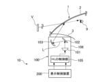
- FIG. 1 is a schematic diagram showing a schematic configuration of a vehicle display system according to an embodiment of the present invention.
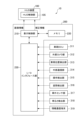
- FIG. 2 is a block diagram showing a schematic configuration of a display control device according to the embodiment.
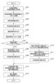
- FIG. 3 is a flowchart showing the process of the display control unit in the embodiment.
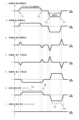
- FIG. 4 is a graph showing the change over time in the acceleration value of a vehicle, the change over time in the vehicle attitude, the change over time in the angular velocity value, the correction amount based on the angular velocity, the correction amount based on the acceleration, a conventional correction state, and a correction state of the present disclosure.
- the mobile object display system of the present disclosure will be described in detail below with reference to the drawings, showing a vehicle display system as an example.
- the mobile object display system can be used as a display system for mobile objects such as vehicles, such as four-wheeled automobiles and two-wheeled automobiles, as well as ships, aircraft, agricultural machinery, and construction machinery.
- FIG. 1 is a schematic diagram showing the general configuration of a vehicle display system according to an embodiment.
- a vehicle display system (display system for a moving object) 10 includes a HUD (head-up display) device (display position adjustment means) 100 and a display control device 200.
- HUD head-up display
- display control device 200 display control device
- the HUD device 100 is installed in the instrument panel 3 of a vehicle (mobile body) 1.
- the HUD device 100 has a display 101, a plane mirror 102, a concave mirror (display position adjustment means) 103, and a HUD control unit (display position adjustment means) 105, and is housed in a housing 106.
- the display 101 is a device that outputs an image (virtual object) for the driver 9 to view as display light L in response to an instruction from the HUD control unit 105.
- a TFT (Thin Film Transistor) type liquid crystal display or an organic EL (Electroluminescence) type display can be used.
- the plane mirror 102 is a mirror that reflects the display light L (image: virtual object) output from the display 101 toward the concave mirror 13
- the concave mirror 103 is a mirror that further reflects the display light L reflected by the plane mirror 102 and emits it toward the windshield (display) 2.
- the concave mirror 103 functions as a magnifying mirror, and magnifies the image (virtual object) of the display light L output from the display 101 before irradiating it onto the windshield 2 of the vehicle 1.
- the driver 9 visually perceives the reflected light of the display light L irradiated onto the windshield 2 as an image (virtual object) V.
- the image (virtual object) V visually perceived by the driver 9 through the windshield 2 is displayed so as to overlap with the actual scene outside (in front of) the windshield 2.
- a projector or a screen constituting a display surface can be installed on the instrument panel 3 or on the windshield 2.
- the HUD control unit 105 performs processing to output an image (display light L) to the display device 101 based on image information received from a display control unit (control means) 210 of the display control device 200 described later. In addition, the HUD control unit 105 adjusts the drawing position of the image on the display device 101 based on correction information received from the display control unit 210, thereby adjusting the display position of the image (virtual object) projected onto the windshield 2.
- FIG. 2 is a block diagram showing a schematic configuration of the display control device 200.
- the display control device 200 includes a display control unit 210, a memory (storage means) 220, and an I/O interface unit (information acquisition means) 230.
- the memory 220 stores image data (sign image, arrow image, etc.) for creating the image (virtual object) V, a program recording the processing contents in the display control unit 210, various data required for processing judgment (threshold data, table data, etc., for example, table data recording the adjustment amount of the display 101 corresponding to the angular velocity information and acceleration information described below), etc.
- a typical recording medium such as a magnetic medium, a volatile memory, or a non-volatile memory is used as the memory 220.
- the I/O interface unit 230 is connected to various devices installed in the vehicle 1, and the display control unit 210 is able to obtain various information from the various devices via the I/O interface unit 230.
- the I/O interface unit 230 can be connected to a vehicle ECU (Electronic Control Unit) 311 capable of acquiring, for example, acceleration information, speed information, and brake operation information based on the amount of power generated by the regenerative brakes of the vehicle 1; an external camera unit 312 capable of acquiring information outside the vehicle 1 (for example, image information capturing the situation in front of or behind the vehicle); a vehicle position detection unit 313 consisting of a GPS (Global Positioning System) or the like for detecting the position of the vehicle; an external communication unit 314 connected to an Internet line or the like for transmitting and receiving various information; an operation detection unit 315 detecting operation information such as the amount of steering of the steering wheel operated by the driver 9 and the amount of depression of the brake pedal and accelerator pedal; an attitude detection unit (attitude detection means) 316 capable of acquiring acceleration
- the I/O interface unit 230 in this embodiment will be described as a posture detection unit 316 that can acquire acceleration information and angular velocity information of the vehicle 1.
- the attitude detection unit 316 is a device provided for the purpose of grasping and estimating the change in attitude of the vehicle 1.
- An IMU Inertial Measurement Unit
- the IMU is equipped with an angular velocity (gyro) sensor (deg/s) of three axes (roll axis: axis extending in the front-rear direction of the vehicle 1, pitch axis: axis extending in the left-right direction of the vehicle 1, and yaw axis: axis extending in the up-down direction of the vehicle 1), an acceleration sensor (m/s 2 ) of three axes (X axis: axis extending in the front-rear direction of the vehicle 1, Y axis: axis extending in the left-right direction of the vehicle 1 , Z axis: axis extending in the up-down direction of the vehicle 1), and the like, and is capable of detecting three-dimensional inertial motion (translational motion and rotational motion in three
- the display control unit 210 is capable of acquiring acceleration information indicating the acceleration of the vehicle 1 and angular velocity information indicating the angular velocity.
- the attitude detection unit 316 detects the acceleration and angular velocity at a predetermined period (a predetermined data rate), and outputs the acceleration information and the angular velocity information to the I/O interface unit 230.
- the display control unit 210 performs a process of creating an image (virtual object) to be projected onto the windshield 2 and outputting it to the HUD control unit 105.
- the display control unit 210 acquires image data of a road sign (such as a maximum speed sign or a no entry sign) from the memory 220 based on a road sign recognized from an image of the road ahead of the vehicle captured by the external camera unit 312, and creates image information of a suitable image V to be projected onto the windshield 2.
- the display control unit 210 acquires image data indicating the vehicle speed (image data indicating the driving speed) from the memory 220 based on speed information acquired from the vehicle ECU 311, and creates image information of the image V.
- the image information created by the display control unit 210 is output in real time to the HUD control unit 105 and projected onto the windshield 2 by the HUD device 100.
- the display control unit 210 also creates correction information for adjusting the display position of the image based on the angular velocity information and acceleration information of the attitude detection unit 316 acquired via the I/O interface unit 230, and performs processing to output the correction information to the HUD control unit 105.
- the HUD control unit 105 adjusts the display position of the image (virtual object) projected onto the windshield 2 by adjusting the positions of the plane mirror 102 and concave mirror 103 based on the correction information acquired from the display control unit 210.
- the display control unit 210 obtains information regarding the reference position from the memory 220, calculates the amount of deviation of the image from the reference position based on changes in the attitude of the vehicle 1, and corrects this amount of deviation, thereby performing a correction process for the display position of the image (virtual object).
- the display control unit 210 also calculates a pitch angle indicating the angle of the front or rear part of the vehicle 1 relative to the vehicle 1 in a horizontal state, a roll angle indicating the angle of the left or right part of the vehicle 1 relative to the vehicle 1 in a horizontal state, and a yaw angle indicating the turning angle of the vehicle 1, based on the angular velocity information acquired from the attitude detection unit 316.
- Methods for calculating the pitch angle, roll angle, and yaw angle based on angular velocity information are well known, and various methods can be used. For example, a method of calculating by integral calculation of angular velocity and a method of calculating using a Kalman filter are known.
- FIG. 3 is a flowchart showing the processing content by the display control unit 210.
- FIG. 4 is a graph showing the change over time in the value of the vehicle's acceleration, the change over time in the vehicle attitude, the change over time in the value of the angular velocity, the amount of correction based on the angular velocity, the amount of correction based on the acceleration, the conventional correction state, and the correction state of the present disclosure.
- the display control unit 210 acquires acceleration information and angular velocity information of the vehicle 1 from the attitude detection unit 316 via the interface unit 230 (S.01). Then, the display control unit 210 records the acquired acceleration information and angular velocity information in the memory 220 (S.02). Note that, as described above, the display control unit 210 acquires acceleration information and angular velocity information from the attitude detection unit 316 at predetermined intervals, and repeatedly executes the process shown in FIG. 3 as described below, so that multiple pieces of acceleration information and angular velocity information acquired at different times (periods) are recorded in chronological order in the memory 220.
- the display control unit 210 calculates the amount of attitude variation of the vehicle 1 based on the acquired angular velocity information (S.03).
- the amount of attitude variation is information that numerically indicates how much the vehicle 1 is tilted from a horizontal state relative to the road surface while the vehicle 1 is traveling, etc.
- the display control unit 210 of the present disclosure calculates the amount of attitude variation as the pitch angle in the fore-and-aft direction of the vehicle 1.
- the display control unit 210 performs a process to correct the display position of the image (virtual object) based on the angular velocity information in order to move the display position of the image in the vertical direction in response to an increase or decrease in the angular velocity.
- the correction amount set by the display control unit 210 is called the angular velocity correction amount because it is a correction amount set in response to the angular velocity.
- the angular velocity correction amount is the amount of movement of the image that is moved in response to the angular velocity, indicated by the amount of adjustment of the drawing position of the image on the display 101, etc.
- the display control unit 210 determines how much the display position of the image has shifted (moved) from the reference position due to the pitch angle, and sets an adjustment amount (correction amount) for adjusting the drawing position of the image on the display unit 101 according to the angular velocity.
- the display unit 101 adjustment amount (correction amount) set according to the angular velocity is recorded in advance in the memory 220 as table data or the like.
- the display control unit 210 sets the angular velocity correction amount by determining the adjustment amount (correction amount) corresponding to the acquired angular velocity information based on the table data.
- the display control unit 210 performs a process of calculating a "delay time (predetermined time)" for executing the "acceleration-based correction process” described below (S.05).
- the following states (1) to (4) can be assumed as situations in which the attitude of the vehicle 1 changes according to the acceleration information.
- the above-mentioned states (1) to (4) are states in which the attitude of the vehicle 1 changes, and therefore the angular velocity values detected by the attitude detection unit 316 also increase or decrease (see the angular velocity values at times T1 to T4 in "3. Change in angular velocity values over time” in FIG. 4).
- the display control unit 210 detects each of the states (1) to (4) and determines each of the times T1 to T4 shown in FIG. 4 as the delay time (predetermined time).
- the display control unit 210 detects the time taken for the acceleration value shown in "1. Change in acceleration value over time” to increase steadily from a fixed value and to return to a fixed value as the delay time (time T1). Specifically, the display control unit 210 calculates the delay time T1 by measuring the time taken for the acceleration value to increase over time from a fixed value and to return to a fixed value based on the acceleration information acquired in the processing of S.01.
- the delay time T1 may be calculated by measuring the time during which the acceleration value shown in "1. Change in acceleration value over time” continues to increase over time, and the time from when the angular velocity value shown in "3. Change in angular velocity value over time” increases over time from a constant value until just before it starts to decrease.
- the delay time T1 may be calculated by measuring the time it takes for the pitch angle value, which indicates "2. Change in vehicle attitude over time,” to increase from a constant value over time and then to return to a constant value again.
- the delay time T1 may be calculated by measuring the time during which the pitch angle value, which indicates "2. Change in vehicle attitude over time,” continues to increase over time, and the time from when the angular velocity value, which is indicated in "3. Change in angular velocity value over time,” increases over time from a constant value until just before it starts to decrease.
- the display control unit 210 performs a process to obtain the delay time T1 in state (1) by one of the methods described above. In the same manner, the display control unit 210 performs a process to obtain delay times T2 to T4 in states (2) to (4) as well as state (1). Note that if the acceleration value remains constant or if the pitch angle, which indicates the change in vehicle attitude over time, remains constant, the increase in acceleration or pitch angle cannot be detected or measured, and therefore the delay time cannot be obtained. In such cases where the delay time cannot be obtained, the display control unit 210 sets Null (empty information) as the delay time.
- the display control unit 210 records the delay time found in S.05 in the memory 220 (S.06). As described above, since the display control unit 210 repeatedly executes the process shown in FIG. 3, the delay time recorded in the memory 220 is not one, but multiple delay times recorded in chronological order. For this reason, even if delay information set to Null continues chronologically, for example, multiple pieces of delay information are recorded in chronological order, so it is possible to detect delay information recorded before the current time in which information other than Null (T1 to T4) is set.
- the display control unit 210 determines whether the delay time obtained at the current time is "any of times T1 to T4" (whether the delay time is other than Null) (S.07), and if the delay time is "any of times T1 to T4" (if the delay time is not Null, Yes in S.07), it acquires acceleration information recorded the delay time (T1 to T4) before the current time from the acceleration information recorded in the memory 220 (see the processing of S.02) (S.08).
- the display control unit 210 extracts/acquires acceleration information recorded a number of times ago (acceleration information acquired a predetermined time ago) calculated by dividing the delay time by the time for one cycle.
- the display control unit 210 sets an acceleration correction amount for correcting (moving (shifting)) the display position of the image based on the acceleration value of the acquired acceleration information (S.09). Specifically, when the acceleration value is positive, the display control unit 210 sets the correction amount so that the display position of the image moves (shifts) downward, and when the acceleration value is negative, the display control unit 210 sets the correction amount so that the display position of the image moves (shifts) upward.
- the correction amount set by the display control unit 210 is called the acceleration correction amount because it is a correction amount set based on the acceleration value.
- the acceleration correction amount is a correction amount that indicates the amount of movement of the image to be moved according to the acceleration value by the adjustment amount of the image drawing position on the display unit 101, etc.
- the display control unit 210 determines how much the display position of the image moves (shifts) from the reference position based on the attitude state (pitch angle) of the vehicle 1, and sets the adjustment amount (correction amount) for adjusting the image drawing position on the display unit 101.
- the adjustment amount (correction amount) of the display unit 101 that is set according to the acceleration is recorded in advance in the memory 220 as table data, etc.
- the display control unit 210 sets the acceleration correction amount by determining the adjustment amount (correction amount) corresponding to the acquired acceleration information based on the table data.
- the display control unit 210 reads out delay information other than Null that was recorded before the current time and that was recorded at the time closest to the current time (recorded in the order closest to the present) from among the multiple delay information recorded in the memory 220 (S.10).
- the display control unit 210 then obtains acceleration information that was recorded before the current time by the delay time of the read delay information from the memory 220 (S.11).
- the display control unit 210 sets an acceleration correction amount for moving the display position of the image based on the acceleration value of the obtained acceleration information (S.12).
- the change in the acceleration correction amount over time is shown as “5. Correction amount based on acceleration.”
- the acceleration correction amount corresponds to the increase or decrease in acceleration shown in "1. Change in acceleration value over time,” and corrects the display position of the image by decreasing the correction amount when acceleration increases and increasing the correction amount when acceleration decreases.
- the acceleration correction amount is configured to delay the correction based on the acceleration value by delay times T1 to T4.
- the display control unit 210 combines the information on the acceleration correction amount (acceleration correction information) set in S.09 or S.12 with the information on the angular velocity correction amount (angular velocity correction information) set in S.04 to set the correction information (S.13).
- the display control unit 210 then outputs the set correction information to the HUD control unit 105 (S.14) and ends the process shown in FIG. 4.
- the HUD control unit 105 adjusts the display position of the image projected on the windshield 2 by adjusting the drawing position of the image on the display 101 based on the correction information acquired from the display control unit 210.
- the display control unit 210 After the process shown in FIG. 4 is completed, the display control unit 210 repeatedly executes the process shown in FIG. 4. By repeatedly executing the process shown in FIG. 4, the display control unit 210 can quickly correct the display position of the image in response to changes in the attitude of the vehicle 1, thereby reducing the visual discomfort felt by the driver 9.
- the display control unit 210 is configured to execute the correction process based on angular velocity without causing a delay, while executing the correction process based on acceleration after a delay time has elapsed.
- the execution timing of the correction process based on angular velocity is not limited to this configuration.
- the acceleration-based correction is started immediately after the angular velocity-based correction is performed (more specifically, at the timing when the angular velocity value changes from increasing to decelerating). For this reason, there may be a delay or the like (for convenience, these times are referred to as "first times") from the time when the control means (display control unit 210) acquires the angular velocity information to the time when the control means sets the correction information using the angular velocity information and outputs the correction information to the display position adjustment means (HUD control unit 105, display 101) (or the time when the correction process for the display position of the image is performed accordingly).
- the first time is shorter than the time from when the control means (display control unit 210) acquires acceleration information to when it sets correction information using the acceleration information and outputs the correction information to the display position adjustment means (HUD control unit 105, display 101) (or the time associated with this, when correction processing of the image display position is performed) (for convenience, these times are referred to as the "second time").
- the delay time (predetermined time) until the acceleration-based correction process is started is calculated based on the time until the acceleration increases or decreases from a constant value and settles back to a constant value. Therefore, if the amount of increase or decrease in acceleration is small, the delay time is short, and if the amount of increase or decrease in acceleration is large, the delay time is long. In this way, the delay time changes depending on the increase or decrease in the amount of increase or decrease in acceleration, and also changes depending on the time until the acceleration increases or decreases from a predetermined value to another value (such as the slope of the increase or decrease in acceleration). Therefore, the display control unit 210 of the present disclosure can vary the delay time depending on the amount of increase or decrease in acceleration, or the changing state of the amount of increase or decrease in acceleration, and can flexibly adjust the time until the display position of the image is corrected.
- the delay time (predetermined time) is determined based on the time it takes for acceleration to increase or decrease from a certain value to reach a certain value, or based on the time it takes for the pitch angle of the vehicle 1 to increase from a certain value to reach a certain value, as examples.
- the delay time is not limited to being set or determined by such methods.
- the change in vehicle posture accompanying the operation of the accelerator pedal or brake pedal has unique characteristics for each vehicle.
- the change in vehicle posture varies depending on the characteristics of the vehicle's suspension and the vehicle weight.
- it is known that a certain pedal operation will cause a certain change in posture in vehicles of similar weight and suspension structure, and it is also possible to set and determine the delay time (predetermined time) for each vehicle in advance using experimental values. For this reason, it is possible to investigate the change in posture accompanying pedal operation for each vehicle in advance through experiments, etc., and determine the delay time (predetermined time) for a certain operation in advance for each vehicle.
- the delay times in the states (1) to (4) described in this disclosure can be determined for each vehicle by experimental values and recorded in advance in memory 220, so that the display control unit 210 can read the delay times from memory 220 for each state (1) to (4) and perform a correction process for the image display position as shown in FIG. 4.
- the delay time is determined based on the acceleration information detected by the attitude detection unit 316, but the acceleration information used to determine the delay time is not limited to that detected by the attitude detection unit 316. For example, it is also possible to use acceleration information determined by the vehicle ECU 311.
- Vehicle ECU 312 ... external camera unit 313 ... vehicle position detection unit 314 ... external communication unit 315 ... operation detection unit 316 ... attitude detection unit (attitude detection means) 317: Vehicle exterior sensor unit 318: Brightness detection unit 319: Information communication terminals T1 to T4: Delay time (predetermined time)
Landscapes
- Engineering & Computer Science (AREA)
- Chemical & Material Sciences (AREA)
- Combustion & Propulsion (AREA)
- Transportation (AREA)
- Mechanical Engineering (AREA)
- Instrument Panels (AREA)
Priority Applications (3)
| Application Number | Priority Date | Filing Date | Title |
|---|---|---|---|
| CN202480040567.3A CN121398987A (zh) | 2023-06-27 | 2024-06-24 | 移动体用显示系统 |
| DE112024002723.7T DE112024002723T5 (de) | 2023-06-27 | 2024-06-24 | Anzeigesystem für beweglichen Körper |
| JP2025530112A JPWO2025005031A1 (cg-RX-API-DMAC7.html) | 2023-06-27 | 2024-06-24 |
Applications Claiming Priority (2)
| Application Number | Priority Date | Filing Date | Title |
|---|---|---|---|
| JP2023-104762 | 2023-06-27 | ||
| JP2023104762 | 2023-06-27 |
Publications (1)
| Publication Number | Publication Date |
|---|---|
| WO2025005031A1 true WO2025005031A1 (ja) | 2025-01-02 |
Family
ID=93939173
Family Applications (1)
| Application Number | Title | Priority Date | Filing Date |
|---|---|---|---|
| PCT/JP2024/022762 Ceased WO2025005031A1 (ja) | 2023-06-27 | 2024-06-24 | 移動体用表示システム |
Country Status (4)
| Country | Link |
|---|---|
| JP (1) | JPWO2025005031A1 (cg-RX-API-DMAC7.html) |
| CN (1) | CN121398987A (cg-RX-API-DMAC7.html) |
| DE (1) | DE112024002723T5 (cg-RX-API-DMAC7.html) |
| WO (1) | WO2025005031A1 (cg-RX-API-DMAC7.html) |
Citations (4)
| Publication number | Priority date | Publication date | Assignee | Title |
|---|---|---|---|---|
| WO2020084954A1 (ja) * | 2018-10-23 | 2020-04-30 | マクセル株式会社 | ヘッドアップディスプレイシステム |
| JP2020157933A (ja) * | 2019-03-26 | 2020-10-01 | パナソニックIpマネジメント株式会社 | 画像表示システム、移動体、画像表示方法及びプログラム |
| WO2020261642A1 (ja) * | 2019-06-27 | 2020-12-30 | パナソニックIpマネジメント株式会社 | 表示制御装置、画像表示システム、移動体、表示制御方法及びプログラム |
| JP2021037917A (ja) * | 2019-09-05 | 2021-03-11 | 株式会社デンソー | 表示制御装置、表示制御プログラム及びヘッドアップディスプレイ |
Family Cites Families (1)
| Publication number | Priority date | Publication date | Assignee | Title |
|---|---|---|---|---|
| JP2022084970A (ja) | 2019-04-11 | 2022-06-08 | パナソニックIpマネジメント株式会社 | 表示システム |
-
2024
- 2024-06-24 JP JP2025530112A patent/JPWO2025005031A1/ja active Pending
- 2024-06-24 WO PCT/JP2024/022762 patent/WO2025005031A1/ja not_active Ceased
- 2024-06-24 DE DE112024002723.7T patent/DE112024002723T5/de active Pending
- 2024-06-24 CN CN202480040567.3A patent/CN121398987A/zh active Pending
Patent Citations (4)
| Publication number | Priority date | Publication date | Assignee | Title |
|---|---|---|---|---|
| WO2020084954A1 (ja) * | 2018-10-23 | 2020-04-30 | マクセル株式会社 | ヘッドアップディスプレイシステム |
| JP2020157933A (ja) * | 2019-03-26 | 2020-10-01 | パナソニックIpマネジメント株式会社 | 画像表示システム、移動体、画像表示方法及びプログラム |
| WO2020261642A1 (ja) * | 2019-06-27 | 2020-12-30 | パナソニックIpマネジメント株式会社 | 表示制御装置、画像表示システム、移動体、表示制御方法及びプログラム |
| JP2021037917A (ja) * | 2019-09-05 | 2021-03-11 | 株式会社デンソー | 表示制御装置、表示制御プログラム及びヘッドアップディスプレイ |
Also Published As
| Publication number | Publication date |
|---|---|
| JPWO2025005031A1 (cg-RX-API-DMAC7.html) | 2025-01-02 |
| CN121398987A (zh) | 2026-01-23 |
| DE112024002723T5 (de) | 2026-04-09 |
Similar Documents
| Publication | Publication Date | Title |
|---|---|---|
| CN111252140B (zh) | 转向判定装置及自动驾驶系统 | |
| JP6787297B2 (ja) | 表示制御装置、及び表示制御プログラム | |
| US11301695B2 (en) | Orientation detection device and non-transitory computer readable medium | |
| JP7211047B2 (ja) | 路面検出装置および路面検出プログラム | |
| US11527013B2 (en) | Camera parameter estimating device, camera parameter estimating method, and camera parameter estimating program | |
| JP2005256636A (ja) | 車両安定化制御システム | |
| CN114025983B (zh) | 显示控制装置及方法、图像显示系统、移动体、记录介质 | |
| JP4835054B2 (ja) | 車両安定化制御システム | |
| JP2018133712A (ja) | 周辺監視装置 | |
| JP2011085999A (ja) | 遠隔操縦システム | |
| WO2019053922A1 (ja) | 画像処理装置 | |
| US12472818B2 (en) | Vehicle display control device, vehicle display device, vehicle, vehicle display control method, and non-transitory storage medium | |
| US10540807B2 (en) | Image processing device | |
| JP6855759B2 (ja) | 自動運転車両の制御システム | |
| US20220062581A1 (en) | Method for reducing the kinetosis effect for passengers of motor vehicles observing an image displayed on a display unit | |
| JP6891863B2 (ja) | 表示制御装置および表示制御プログラム | |
| WO2018025441A1 (ja) | 周辺監視装置 | |
| JP7790226B2 (ja) | 表示制御装置、及び表示制御プログラム | |
| JP2021081989A (ja) | カメラキャリブレーション装置 | |
| CN121398987A (zh) | 移动体用显示系统 | |
| WO2025005032A1 (ja) | 移動体用表示システム | |
| JP2025014541A (ja) | 移動体用表示システム、及び表示制御装置 | |
| JP2025017412A (ja) | 表示制御装置およびヘッドアップディスプレイ装置 | |
| US12570273B2 (en) | Parking assistance method and parking assistance device | |
| US20240328809A1 (en) | Surrounding display device |
Legal Events
| Date | Code | Title | Description |
|---|---|---|---|
| 121 | Ep: the epo has been informed by wipo that ep was designated in this application |
Ref document number: 24831892 Country of ref document: EP Kind code of ref document: A1 |
|
| ENP | Entry into the national phase |
Ref document number: 2025530112 Country of ref document: JP Kind code of ref document: A |
|
| WWE | Wipo information: entry into national phase |
Ref document number: 112024002723 Country of ref document: DE |
|
| WWP | Wipo information: published in national office |
Ref document number: 112024002723 Country of ref document: DE |
|
| 122 | Ep: pct application non-entry in european phase |
Ref document number: 24831892 Country of ref document: EP Kind code of ref document: A1 |