WO2025004808A1 - 音検出装置 - Google Patents
音検出装置 Download PDFInfo
- Publication number
- WO2025004808A1 WO2025004808A1 PCT/JP2024/021352 JP2024021352W WO2025004808A1 WO 2025004808 A1 WO2025004808 A1 WO 2025004808A1 JP 2024021352 W JP2024021352 W JP 2024021352W WO 2025004808 A1 WO2025004808 A1 WO 2025004808A1
- Authority
- WO
- WIPO (PCT)
- Prior art keywords
- outer cover
- hole
- detection device
- cover part
- sound detection
- Prior art date
- Legal status (The legal status is an assumption and is not a legal conclusion. Google has not performed a legal analysis and makes no representation as to the accuracy of the status listed.)
- Ceased
Links
Images






Classifications
-
- G—PHYSICS
- G01—MEASURING; TESTING
- G01H—MEASUREMENT OF MECHANICAL VIBRATIONS OR ULTRASONIC, SONIC OR INFRASONIC WAVES
- G01H3/00—Measuring characteristics of vibrations by using a detector in a fluid
-
- H—ELECTRICITY
- H04—ELECTRIC COMMUNICATION TECHNIQUE
- H04R—LOUDSPEAKERS, MICROPHONES, GRAMOPHONE PICK-UPS OR LIKE ACOUSTIC ELECTROMECHANICAL TRANSDUCERS; ELECTRIC HEARING AIDS; PUBLIC ADDRESS SYSTEMS
- H04R1/00—Details of transducers, loudspeakers or microphones
-
- H—ELECTRICITY
- H04—ELECTRIC COMMUNICATION TECHNIQUE
- H04R—LOUDSPEAKERS, MICROPHONES, GRAMOPHONE PICK-UPS OR LIKE ACOUSTIC ELECTROMECHANICAL TRANSDUCERS; ELECTRIC HEARING AIDS; PUBLIC ADDRESS SYSTEMS
- H04R1/00—Details of transducers, loudspeakers or microphones
- H04R1/08—Mouthpieces; Microphones; Attachments therefor
Definitions
- This disclosure relates to a sound detection device.
- Sound detection devices equipped with a cover have been proposed in the past (see, for example, Patent Document 1). Specifically, in this sound detection device, the cover is arranged so that foreign objects are less likely to reach the sensor that outputs a detection signal corresponding to sound.
- the cover is made of a mesh or the like with holes formed therein, and is configured so that sound can be introduced through the holes.
- such a sound detection device may allow foreign matter such as water to enter through the hole in the cover.
- the sound detection device when used as a detection unit that detects sound generated by a machine tool, the sound detection device is placed in an environment where foreign matter such as water or oil is likely to scatter, increasing the possibility of foreign matter entering through the hole in the cover. If the foreign matter reaches the sensor unit, the detection accuracy of the sensor unit may decrease.
- the present disclosure aims to suppress a decrease in the detection accuracy of a sensor unit.
- the sound detection device includes a sensor unit that outputs a detection signal in response to a sound, a case in which the sensor unit is disposed, and a cover unit that is attached to the case to protect the sensor unit, and at least one of the case and the cover unit is formed with an ejection structure that ejects foreign matter.
- an exhaust structure is formed in at least one of the case and the cover portion. This makes it easier to exhaust foreign matter through the exhaust structure, and prevents foreign matter from reaching the sensor portion. This prevents a decrease in detection accuracy.
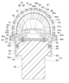
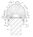
- FIG. 2 is a cross-sectional view of the sound detection device according to the first embodiment.
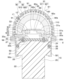
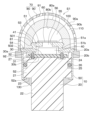
- FIG. 11 is a cross-sectional view of a sound detection device according to a second embodiment.
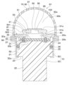
- FIG. 11 is a cross-sectional view of a sound detection device according to a third embodiment.
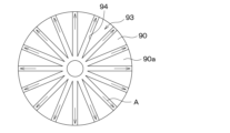
- FIG. 13 is a plan view of a cover portion in the fourth embodiment.
- FIG. 13 is a cross-sectional view of the vicinity of the outer edge of the lid portion in the fifth embodiment.
- FIG. 13 is a cross-sectional view of a sound detection device according to a sixth embodiment.
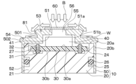
- 11 is a cross-sectional view for explaining a state when a foreign object enters the inside of the cover.
- FIG. FIG. 13 is a cross-sectional view of a sound detection device according to a seventh embodiment.
- FIG. 11 is a diagram showing the relationship between the size of the tapered portion, the frequency of the applied sound, and the sound pressure.
- FIG. 11 is a diagram for explaining the relationship between the diameter of the bottom portion and the size of the tapered portion.
- FIG. FIG. 23 is a cross-sectional view of a sound detection device according to an eighth embodiment.
- FIG. 13 is a cross-sectional view of a sound detection device according to a ninth embodiment.
- FIG. 23 is a cross-sectional view of a sound detection device according to a tenth embodiment.
- FIG. 23 is a cross-sectional view of a sound detection device according to an eleventh embodiment.
- FIG. 23 is a cross-sectional view of a sound detection device according to a twelfth embodiment.
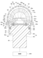
- FIG. 23 is a cross-sectional view of a sound detection device according to a thirteenth embodiment.
- a sound detection device S1 of the present embodiment is suitably used as a detection unit that detects sound generated from a machine tool, for example.
- the sound detection device S1 is configured to include a case 10, a wiring board 30, a sensor unit 40, a waterproof membrane 60, a cover unit 70, etc.
- the case 10 is configured by assembling a connector case 20 and a lid portion 50.
- the connector case 20 is made of, for example, a heat-resistant resin material such as PPS (i.e., polyphenylene sulfide) or a metal material such as SUS, and is generally cylindrical.
- the connector case 20 of this embodiment is configured such that a step portion 23 is provided between a first portion 21 at one end side and a second portion 22 at the other end side.
- the connector case 20 has a circumferential length of the first portion 21 longer than the circumferential length of the second portion 22.
- the connector case 20 has a length of the opposing side of the first portion 21 longer than the opposing side of the second portion 22 in a cross section along the axial direction.
- the upper portion of the connector case 20 on the paper surface is the first portion 21, and the lower portion on the paper surface is the second portion 22.
- the up-down direction on the paper surface is the axial direction
- the circumferential direction is the direction around the axial direction.
- the cross section along the axial direction is, for example, FIG. 1.
- the connector case 20 has a recess 24 formed in one face 20a on one end side.
- the one face 20a of the connector case 20 is formed so that the normal direction to the one face 20a (hereinafter simply referred to as the normal direction) coincides with the axial direction.
- the connector case 20 also has an annular groove 25 formed in the side face 20b connected to the one face 20a, and a sealing member 26 such as an O-ring is disposed in the groove 25.
- the groove 25 is formed so as to go around the side face 20b of the first portion 21 in the circumferential direction.
- the lid 50 constituting the case 10 will be described later.
- the wiring board 30 is composed of a printed circuit board or the like having one surface 30a and the other surface 30b. Although not specifically shown, the wiring board 30 of this embodiment has one-surface wiring formed on the one surface 30a and other-surface wiring formed on the other surface 30b, and through-hole wiring connecting the one-surface wiring and the other-surface wiring is appropriately formed. The wiring board 30 is then placed in the recess 24 with the other surface 30b facing the bottom surface of the recess 24.
- the wiring board 30 has a through hole 31 formed at its outer edge, penetrating between one surface 30a and the other surface 30b, and the terminal 27 is inserted into the through hole 31.
- the wiring board 30 is connected to the terminal 27 by arranging a conductive member 32 such as solder in the through hole 31.
- the terminal 27 is, for example, rod-shaped and arranged in the connector case 20. Specifically, the terminal 27 is arranged in the connector case 20 so that the end on the wiring board 30 side is exposed from the recess 24 and the end on the opposite side to the wiring board 30 side is exposed from a predetermined position of the connector case 20. The end of the terminal 27 on the opposite side to the wiring board 30 side is connected to an external circuit unit, thereby connecting the wiring board 30 to the external circuit unit.
- the sensor unit 40 includes a detection element that outputs a detection signal according to the applied sound, and is disposed on one surface 30a of the wiring board 30 and electrically connected to the wiring board 30. This allows the sensor unit 40 to be connected to an external circuit unit via the wiring board 30 and the terminal 27.
- the detection element is not particularly limited, but may be, for example, a piezoelectric type, electrostatic type, or capacitor type.
- the sensor unit 40 may be a package in which the detection element is housed in a box-shaped container with an introduction hole for introducing sound, or may be composed of only the detection element.
- the lid 50 is made of a metal material such as SUS, and is a bottomed cylinder having a bottom 51 and a side 52.
- the lid 50 is assembled to the connector case 20 by crimping the open end 52a of the side 52 to the step 23 of the connector case 20 so that the sealing member 26 is crushed by the side 52 while the bottom 51 faces one surface 20a of the connector case 20.
- an accommodation space 41 is formed between the lid 50 and the recess 24 of the connector case 20, and the sensor unit 40 is disposed in the accommodation space 41.
- the surface of the bottom 51 opposite the sensor unit 40 will be referred to as one surface 51a of the bottom 51, and the surface on the sensor unit 40 side will be referred to as the other surface 51b of the bottom 51.
- the lid 50 has a convex portion 53 formed in the center of the bottom 51 that protrudes toward the one surface 51a.
- the lid 50 has a step portion 54 formed in the outer edge of the bottom 51 that is recessed toward the other surface 51b.
- the one surface 51a and the other surface 51b of the bottom 51 in this embodiment have their central portions protruding toward the one surface 51a more than the outer edge portions.
- the convex portion 53 is sized to accommodate a portion of the sensor unit 40 therein.
- the lid 50 is attached to the connector case 20 so that a portion of the sensor unit 40 is accommodated within the convex portion 53.
- the lid 50 has a through hole 55 formed between the one surface 51a and the other surface 51b in the portion of the bottom 51 facing the sensor unit 40. As a result, sound is applied to the sensor unit 40 through the through hole 55.
- a convex portion 53 is formed in the center of the lid 50, and a through hole 55 is formed in the convex portion 53.
- the space inside the through hole 55 becomes a so-called acoustic space 56, and the size is appropriately changed depending on the frequency of the sound to be detected, etc.
- the lid portion 50 is also formed with a first engaging fixing portion 501 for engaging with the inner cover portion 80 (described below) to fix the inner cover portion 80, and a second engaging fixing portion 502 for engaging with the outer cover portion 90 (described below) to fix the outer cover portion 90.
- the first engaging fixing portion 501 is formed on the outer edge of the convex portion 53 and is a convex portion that protrudes along the surface direction of the one surface 51a.
- the second engaging fixing portion 502 is formed on the outer edge of the step portion 54 and is a convex portion that protrudes along the surface direction of the one surface 51a.
- the waterproof membrane 60 is made of a porous material such as fluororesin.
- the waterproof membrane 60 is arranged so as to block the through-hole 55 of the lid 50.
- the waterproof membrane 60 is arranged on one surface 51a of the bottom 51, but the waterproof membrane 60 may be arranged on the other surface 51b of the bottom 51.
- the waterproof membrane 60 corresponds to a preventive membrane. Note that in this embodiment, the waterproof membrane 60 is arranged because it is assumed that water may enter as a foreign object, but in a state in which oil may enter as a foreign object, an oil-proof membrane may be arranged instead of the waterproof membrane 60.
- the cover section 70 is attached to the case 10 to protect the sensor section 40, and in this embodiment, is configured to have an inner cover section 80 and an outer cover section 90.
- the outer cover section 90 is disposed so as to cover the inner cover section 80.
- the inner cover portion 80 is made of a windscreen member that is a porous material such as sponge, and is hemispherical with an outer surface 80a and an inner surface 80b.
- the inner cover portion 80 is generally bowl-shaped with a recess formed on the inside so that a cavity is formed on the inner surface 80b side.
- the inner cover portion 80 may be made of a material that easily absorbs (i.e., easily attenuates) specific frequencies. For example, if it is desired to absorb sounds related to human voices, the inner cover portion 80 may be made of a material that easily absorbs sounds of 3 to 4 kHz.
- the inner cover part 80 has a third engaging fixing part 81 formed on the inner surface 80b, which corresponds to the first engaging fixing part 501 of the lid part 50.
- the inner cover part 80 is fixed to the lid part 50 by engaging the third engaging fixing part 81 with the first engaging fixing part 501 with the outer edge part abutting against the step part 54 of the lid part 50.
- the third engaging fixing part 81 is a recess, and the protrusion of the first engaging fixing part 501 is snap-fitted into this recess.
- the inside of the inner cover part 80 is hollow. Therefore, when the inner cover part 80 is fixed to the lid part 50, an internal space 100 is formed between the inner cover part 80 and the lid part 50.
- the outer cover part 90 is made of a hard material such as a metal material or resin that has a higher Young's modulus than the inner cover part 80, and is configured with holes 91 that allow foreign matter to enter more easily than the inner cover part 80.
- the outer cover part 90 is made of a mesh member made of woven metal wires, punched metal, etc.
- the outer cover part 90 is formed in a semi-spherical shape with an arcuate cross section corresponding to the inner cover part 80 so as to cover the inner cover part 80.
- the surface of the outer cover part 90 facing the inner cover part 80 will be referred to as the inner surface 90b, and the surface opposite the inner cover part 80 will be referred to as the outer surface 90a.
- the outer cover part 90 has a fourth engaging fixing part 92 formed at its outer edge.
- the outer cover part 90 is fixed to the lid part 50 by engaging the fourth engaging fixing part 92 with the second engaging fixing part 502.
- the fourth engaging fixing part 92 is a convex part, and this convex part is snap-fitted to the convex part of the second engaging fixing part 502.
- the inner cover part 80 and the outer cover part 90 are fixed to the lid part 50 with a predetermined space (i.e., gap) 110 between the inner cover part 80 and the outer cover part 90. Therefore, foreign matter that enters the interior through the hole 91 of the outer cover part 90 is more likely to move along the inner surface 90b of the outer cover part 90 than to move toward the inner cover part 80. Therefore, it is possible to prevent foreign matter from reaching the inner cover part 80 and then the sensor part 40 via the inner cover part 80.
- the above is the configuration of the sound detection device S1 in this embodiment.
- a sound detection device S1 is placed, for example, near the target part that emits the sound to be detected.
- the sensor unit 40 outputs a detection signal corresponding to the sound when the sound generated by the target part is applied through the cover unit 70, the internal space 100, and the acoustic space 56.
- the cover section 70 is configured to have an outer cover section 90 made of a hard material, and an inner cover section 80 made of a windscreen material, which is a porous material. Therefore, even if a foreign object enters through the hole 91 of the outer cover section 90, the inner cover section 80 can prevent the foreign object from reaching the sensor section 40, and a decrease in detection accuracy can be prevented.
- the outer cover section 90 is made of a hard material, impact resistance can also be improved.
- a space 110 is formed between the inner cover portion 80 and the outer cover portion 90. For this reason, foreign matter that enters the interior through the hole 91 of the outer cover portion 90 is more likely to move along the inner surface 90b of the outer cover portion 90 than to move toward the inner cover portion 80. This prevents foreign matter from reaching the inner cover portion 80 and then the sensor portion 40 via the inner cover portion 80.
- the waterproof membrane 60 is disposed so as to block the through-hole 55. This further prevents water as a foreign object from reaching the sensor unit 40.
- Second Embodiment A second embodiment will be described.
- the configurations of the inner cover part 80 and the outer cover part 90 are changed from those in the first embodiment.
- the rest of the configuration is the same as that of the first embodiment, the description thereof will be omitted here.
- the sound detection device S1 of this embodiment is designed for a situation in which water may enter as a foreign object.
- the inner cover part 80 has a water-repellent part 82 formed on the outer surface 80a.
- the outer cover part 90 has a water-repellent part 93 formed on the outer surface 90a.
- the water-repellent parts 82 and 93 are made of, for example, an organic fluorine compound film.
- the cover portion 70 is configured to have an outer cover portion 90 and an inner cover portion 80, so that the same effects as those of the first embodiment can be obtained.
- a water-repellent portion 82 is formed on the inner cover portion 80, and a water-repellent portion 93 is formed on the outer cover portion 90. This makes it possible to prevent water from remaining as a foreign object in the cover portion 70, and further to prevent foreign objects from reaching the sensor portion 40.
- the inner cover part 80 may be formed with an oil repellent part instead of the water repellent part 82, and the outer cover part 90 may be formed with an oil repellent part instead of the water repellent part 93.
- the oil generating part is composed of, for example, a fluorine-based polymer or the like.
- the water-repellent portion 82 may be formed on the outer surface 80a and the inner surface 80b of the inner cover portion 80, and the water-repellent portion 93 may be formed on the outer surface 90a and the inner surface 90b of the outer cover portion 90. Furthermore, the water-repellent portion 82 may be formed only on the inner surface 80b of the inner cover portion 80, and the water-repellent portion 93 may be formed only on the inner surface 90b of the outer cover portion 90. Also, only one of the water-repellent portion 82 of the inner cover portion 80 and the water-repellent portion 93 of the outer cover portion 90 may be formed.
- the cover portion 70 may be composed of either the inner cover portion 80 or the outer cover portion 90, and the water-repellent portions 82, 93 may be provided on one of the cover portions.
- the cover portion 70 is composed of only the inner cover portion 80, the holes of the cover portion 70 are composed of the holes of the porous material that composes the inner cover portion 80.
- the sound detection device S1 of this embodiment is configured such that the outer cover part 90 has a first outer cover part 910 and a second outer cover part 920.
- the first outer cover part 910 and the second outer cover part 920 are arranged in the order of the first outer cover part 910 and the second outer cover part 920 from the side opposite the inner cover part 80, and are integrated by sintering or the like. Therefore, in this embodiment, the outer surface 90a of the outer cover part 90 is formed by the first outer cover part 910, and the inner surface 90b of the outer cover part 90 is formed by the second outer cover part 920.
- the first outer cover part 910 and the second outer cover part 920 may be integrated by an adhesive or the like.
- the first outer cover part 910 and the second outer cover part 920 have a higher Young's modulus than the second outer cover part 920.
- the first outer cover part 910 has a hole 911 formed therein
- the second outer cover part 920 has a hole 921 formed therein.
- the size of the opening of each hole 911, 921 is smaller in the second outer cover part 920 than in the first outer cover part 910.
- the opening area of the hole 921 of the second outer cover part 920 is smaller than that of the hole 911 of the first outer cover part 910. That is, the hole 921 of the second outer cover part 920 is sized to make it more difficult for foreign objects to enter than the hole 911 of the first outer cover part 910.
- the hole 921 of the second outer cover part 920 is sized to at least satisfy IP6X.
- IP6X is a size that prevents the intrusion of a substance with a diameter of 1 mm.
- the hole 91 of the outer cover part 90 is formed at the portion where the hole 911 of the first outer cover part 910 and the hole 921 of the second outer cover part 920 communicate with each other.
- the thickness t2 of the second outer cover part 920 is thinner than the thickness t1 of the first outer cover part 910.
- the cover portion 70 is configured to have an outer cover portion 90 and an inner cover portion 80, so that the same effects as those of the first embodiment can be obtained.
- the outer cover part 90 is configured by integrating a first outer cover part 910 and a second outer cover part 920.
- the second outer cover part 920 has a hole 921 that is smaller than the hole 911 of the first outer cover part 910. Therefore, compared to when the outer cover part 90 is configured only by the first outer cover part 910, it is possible to further prevent foreign matter from entering the interior, and to further prevent a decrease in detection accuracy.
- the thickness t2 of the second outer cover part 920 is thinner than the thickness t1 of the first outer cover part 910. Therefore, compared to when the thickness t2 of the second outer cover part 920 is the same as the thickness t1 of the first outer cover part 910, the attenuation of sound passing through the hole 921 can be reduced. Therefore, the detection accuracy can be improved.
- the first outer cover part 910 has a higher Young's modulus than the second outer cover part 920. Therefore, impact resistance can be improved compared to a case in which the Young's modulus of the first outer cover part 910 is the same as the Young's modulus of the second outer cover part 920.
- the cover portion 70 may be configured only with the outer cover portion 90 without including the inner cover portion 80.
- an exhaust path 94 is formed on the outer surface 90a of the outer cover part 90.
- the exhaust path 94 is a recess formed in a part different from the hole portion 91, and is formed so as to extend radially from the center of the outer cover part 90 in the normal direction. Note that FIG. 4 omits the hole portion 91. In addition, in the normal direction can also be said to be when viewed from the normal direction.
- the exhaust path 94 corresponds to the exhaust structure.
- the outer cover part 90 has a water-repellent part 93 formed in a part different from the discharge passage 94, similar to the second embodiment described above.
- the cover portion 70 is configured to have an outer cover portion 90 and an inner cover portion 80, so that the same effects as those of the first embodiment can be obtained.
- an exhaust passage 94 is formed in the outer cover part 90. This makes it easier to exhaust foreign matter from the outer cover part 90 through the exhaust passage 94.
- the sound detection device S1 is positioned so that the connector case 20 is on the bottom side in the vertical direction and the outer cover part 90 is on the top side in the vertical direction, foreign matter flows to the outer edge of the outer cover part 90 as shown by arrow A and is exhausted.
- the sound detection device S1 is positioned so that the connector case 20 is on the top side in the vertical direction and the outer cover part 90 is on the bottom side in the vertical direction, foreign matter flows in the opposite direction to arrow A, gathers at the center of the outer cover part 90 and is exhausted.
- the outer cover portion 90 has a water-repellent portion 93 formed in a portion different from the discharge passage 94. Therefore, in a situation where water may enter as a foreign object, the foreign object that reaches the outer cover portion 90 is more likely to be guided to the discharge passage 94 and is more likely to be discharged from the discharge passage 94. Therefore, it is possible to prevent foreign objects from entering the interior of the outer cover portion 90.
- the water-repellent portion 93 may also be formed in the discharge path 94. In other words, when the water-repellent portion 93 is formed, it is sufficient that the water-repellent portion 93 is formed at least in a portion different from the discharge path 94.
- the cover portion 70 may not include the inner cover portion 80 and may be composed of only the outer cover portion 90. Also, in the fourth embodiment, the water-repellent portion 93 may not be formed. Such a sound detection device S1 can also easily discharge foreign matter from the discharge path 94.
- the sound detection device S1 of this embodiment is configured such that the outer cover part 90 has a first outer cover part 910 and a second outer cover part 920.
- the second outer cover part 920 is configured such that the outer edge ends on the inside of the outer edge of the first outer cover part 910, and the outer edge ends are arranged so as to be separated from one surface 51a of the bottom part 51 of the lid part 50.
- a predetermined gap G is formed between the outer edge of the second outer cover part 920 and one surface 51a of the bottom part 51 of the lid part 50. Therefore, the hole part 911 on the outer edge side of the first outer cover part 910 is exposed from the second outer cover part 920.
- the shape of the second outer cover part 920 corresponds to the exhaust structure.
- FIG. 5 corresponds to an enlarged view of the area V in FIG. 3.
- the lid portion 50 is configured to have the protrusion 53 and the step portion 54 as described above.
- the outer edge of the second outer cover portion 920 is disposed in a position facing the step portion 54 in the normal direction, and is shaped so that the gap G between the step portion 54 and the surface 51a is shorter than the height of the protrusion 53.
- the outer edge of the second outer cover portion 920 is disposed so as to be located closer to the step portion 54 than an imaginary plane along the surface 51a of the protrusion 53.
- the outer edge of the second outer cover portion 920 is shaped so as to be located between the height of the portion of the surface 51a where the through hole 55 is formed and the height of the portion of the first outer cover portion 910 that is assembled to the lid portion 50.
- the cover portion 70 is configured to have an outer cover portion 90 and an inner cover portion 80, so that the same effects as those of the first embodiment can be obtained.
- the second outer cover part 920 is arranged so that its outer edge is separated from one surface 51a of the bottom part 51 of the lid part 50. Therefore, when a foreign object enters the inner surface 90b of the outer cover part 90 and moves along the inner surface 90b to the outer edge, the foreign object is transferred from the second outer cover part 920 to the first outer cover part 910.
- the hole 911 of the first outer cover part 910 is larger than the hole 921 of the second outer cover part 920. Therefore, it is expected that the foreign object that reaches the first outer cover part 910 will be discharged to the outer surface 90a of the first outer cover part 910 through the hole 911. Therefore, it is possible to prevent the foreign object from being retained inside the cover part 70.
- the lid portion 50 has a convex portion 53 and a step portion 54.
- the outer edge portion of the second outer cover portion 920 is disposed in a position facing the step portion 54 in the normal direction, and the gap G between the step portion 54 and one surface 51a is shaped to be shorter than the height of the convex portion 53. This makes it possible to prevent foreign matter from reaching the one surface 51a of the convex portion 53, and further prevents foreign matter from reaching the sensor portion 40 through the through hole 55.
- the cover portion 70 may be configured only with the outer cover portion 90 without including the inner cover portion 80.
- Sixth Embodiment A sixth embodiment will be described. This embodiment differs from the first embodiment in that it does not include the inner cover portion 80. As the rest is similar to the first embodiment, a description thereof will be omitted here.
- the sound detection device S1 of this embodiment does not have an inner cover portion 80.
- the cover portion 70 is composed of an outer cover portion 90.
- the bottom portion 51 is configured with a convex portion 53 and a step portion 54. Therefore, when a foreign object reaches the bottom portion 51, as shown by arrow B in FIG. 7, the foreign object W flows toward the step portion 54 side, thereby preventing the foreign object W from accumulating near the through hole 55. Therefore, the foreign object W can be prevented from reaching the sensor portion 40 through the through hole 55.
- FIG. 7 does not show the cover portion 70, etc.
- the shape of the bottom portion 51 corresponds to the discharge structure.
- the bottom 51 is configured to have the convex portion 53 and the step portion 54, so that it is possible to prevent foreign matter from reaching the sensor unit 40 through the through hole 55, and to prevent a decrease in detection accuracy.
- This effect can also be obtained when the sensor has an inner cover portion 80 as in the first embodiment described above.
- the cover portion 70 may be configured with an inner cover portion 80 without including the outer cover portion 90.
- Seventh Embodiment A seventh embodiment will be described.
- a tapered portion is formed on the bottom portion 51 of the lid portion 50 in comparison with the sixth embodiment.
- the rest is similar to the sixth embodiment, a description thereof will be omitted here.
- the bottom 51 of the lid 50 has a reference position at the portion of the protrusion 53 where the through hole 55 is formed, and is tapered such that the surface 51a approaches the connector case 20 from the reference position toward the outer edge.
- the bottom 51 is shaped so that the portion where the through hole 55 is formed protrudes the most, and the surface 51a slopes toward the connector case 20 from this portion toward the outer edge.
- the portion of the surface 51a that slopes toward the connector case 20 will be described as a tapered portion 511. Note that FIG. 8 omits the cover portion 70 and the like.
- the shape of the bottom 51 corresponds to the exhaust structure.
- the bottom portion 51 has a reference position at which the through hole 55 is formed, and the one surface 51a is tapered from this reference position toward the outer edge portion so that it approaches the connector case 20 side. Therefore, if a foreign object reaches the bottom portion 51, the foreign object flows toward the outer edge end portion as shown by arrow C in FIG. 8, and therefore it is possible to prevent the foreign object from reaching the sensor portion 40 through the through hole 55.
- the portion of the bottom 51 where the through hole 55 is formed is set as the reference position, and the surface 51a is tapered from this reference position toward the outer edge toward the connector case 20. This makes it possible to prevent foreign matter from reaching the sensor unit 40 through the through hole 55, and to prevent a decrease in detection accuracy.
- the bottom 51 has a reference position at which the through hole 55 is formed, and one surface 51a is tapered from this reference position toward the outer edge toward the connector case 20. Therefore, as described above, it is possible to prevent foreign matter from reaching the sensor unit 40 and to prevent a decrease in detection accuracy.
- the inventors have carefully examined the relationship between the size of the tapered portion 511, the frequency of the applied sound, and the sound pressure (i.e., the detection signal), and obtained the results shown in FIG. 9A.
- the size of the tapered portion in FIG. 9A is the ratio of the length Rb of the tapered portion 511 along the radial direction to the diameter Ra of the lid portion 50 shown in FIG. 9B (i.e., (Rb/Ra) ⁇ 100).
- FIG. 9A shows the result of forming the tapered portion 511 in a ring shape around the through hole 55 with the angle ⁇ of the tapered portion 511 shown in FIG. 9B set to 45°.
- FIG. 9A it has been confirmed that when the frequency of the applied sound is in the range of 15,000 Hz or less, the sound pressure does not change much even if the size of the tapered portion 511 is changed. Note that in the range of 15,000 Hz or less in FIG. 9A, the results are almost the same and overlap, so the solid line without the tapered portion is mainly shown, but in reality, it has been confirmed that the sound pressure is similar even when the size of the tapered portion is changed. In other words, according to the sound detection device S1 of this embodiment, when the frequency of the applied sound is 15,000 Hz or less, the characteristics are not changed, and it is possible to prevent foreign objects from reaching the sensor unit 40 and prevent a decrease in detection accuracy.
- the cover portion 70 may have an inner cover portion 80, similar to the first embodiment. Also, in the seventh embodiment, the cover portion 70 may be configured with the inner cover portion 80 without including the outer cover portion 90.
- an eighth embodiment will be described.
- an induction hole is formed in the inner cover part 80.
- the rest is similar to the first embodiment, a description thereof will be omitted here.
- an induction hole 83 is formed in the inner cover portion 80, penetrating between the outer surface 80a and the inner surface 80b.
- the induction hole 83 is formed so that its axis coincides with the axis of the through hole 55. In other words, the induction hole 83 is formed directly above the through hole 55.
- the cover portion 70 is configured to have an outer cover portion 90 and an inner cover portion 80, so that the same effects as those of the first embodiment can be obtained.
- an induction hole 83 is formed in the inner cover part 80. Therefore, when sound passes through the inner cover part 80, the attenuation of the sound can be suppressed in the area of the induction hole 83. This makes it possible to improve the detection accuracy. In addition, by forming the induction hole 83, the attenuation of the sound can be suppressed in the area of the induction hole 83, so it is also possible to provide directionality in the detection direction.
- the portion where the guide hole 83 is formed can be appropriately changed according to the direction in which directivity is desired.
- the cover portion 70 may be configured by the inner cover portion 80 without including the outer cover portion 90.
- Ninth embodiment A ninth embodiment will be described.
- the configuration of the inner cover portion 80 is changed from that of the first embodiment.
- the description will be omitted here.
- the inner cover part 80 has no cavity formed on the inner surface 80b side.
- the inner cover part 80 is also positioned so as to abut against one surface 51a of the protrusion 53 and close the through hole 55. For this reason, in this embodiment, an internal space 100 is not formed between the inner cover part 80 and the lid part 50. Furthermore, because the inner cover part 80 is positioned so as to close the through hole 55, a waterproof membrane 60 is not provided.
- the cover portion 70 is configured to have an outer cover portion 90 and an inner cover portion 80, so that the same effects as those of the first embodiment can be obtained.
- the inner cover portion 80 is arranged to abut against one surface 51a of the protrusion 53. This makes it difficult for a space to exist between the inner cover portion 80 and the protrusion 53, which can prevent sound from scattering between the inner cover portion 80 and the protrusion 53.
- the waterproof membrane 60 may be provided.
- the cover portion 70 may be configured with the inner cover portion 80 without including the outer cover portion 90.
- Tenth embodiment A tenth embodiment will be described. This embodiment is different from the first embodiment in that a filling member is provided. As the rest is similar to the first embodiment, a description thereof will be omitted here.
- a filling member 120 made of gel or the like is disposed in the storage space 41 between the inner cover portion 80 and the connector case 20.
- the filling member 120 is disposed in a portion of the sensor portion 40 that is different from the portion that overlaps with the through-hole 55 in the normal direction.
- the filling member 120 is disposed in a portion of the sensor portion 40 that is different from the portion to which sound is likely to be applied through the through-hole 55.
- the cover portion 70 is configured to have an outer cover portion 90 and an inner cover portion 80, so that the same effects as those of the first embodiment can be obtained.
- the filling member 120 is disposed in the storage space 41 between the inner cover portion 80 and the connector case 20. This makes it possible to prevent sound from entering the storage space 41 and to prevent sound from reverberating within the storage space 41. This improves detection accuracy.
- the filling member 120 is disposed in a portion of the sensor unit 40 that is different from the portion that overlaps with the through hole 55 in the normal direction. This makes it possible for the filling member 120 to prevent sound from being difficult to transmit to the sensor unit 40.
- the cover portion 70 may be composed of one of the inner cover portion 80 and the outer cover portion 90.
- a protective member 130 is disposed at the portion where the cover 50 is crimped to the connector case 20.
- the protective member 130 is made of, for example, potting resin.
- the cover portion 70 is configured to have an outer cover portion 90 and an inner cover portion 80, so that the same effects as those of the first embodiment can be obtained.
- the protective member 130 is disposed at the portion where the lid portion 50 is crimped to the connector case 20. This prevents foreign matter from entering between the connector case 20 and the lid portion 50, and prevents excess stress from being generated at the crimped portion. This allows the sound detection device S1 to have a long life.
- the cover portion 70 may be composed of one of the inner cover portion 80 and the outer cover portion 90.
- Twelfth Embodiment A twelfth embodiment will be described. This embodiment is different from the first embodiment in that the shape of the connector case 20 is changed and a mounting member is added. As the rest is similar to the first embodiment, a description thereof will be omitted here.
- the second portion 22 of the connector case 20 has a shape that widens from the first portion 21 side toward the opposite side to the first portion 21 side.
- the second portion 22 of the connector case 20 has a tapered shape in which the length of the opposing side gradually increases from the first portion 21 side toward the opposite side to the first portion 21 side in a cross section along the axial direction.
- the sound detection device S1 has a magnet 140 disposed as an attachment member at the other end of the second part 22 opposite the first part 21.
- the cover portion 70 is configured to have an outer cover portion 90 and an inner cover portion 80, so that the same effects as those of the first embodiment can be obtained.
- the second portion 22 of the connector case 20 has a fan-shaped shape that widens from the first portion 21 side toward the opposite side to the first portion 21 side. Therefore, when attaching the second portion 22 side of the sound detection device S1 to a mounting member such as a machine tool, the mounting area can be made wider, making the mounting easier. Furthermore, in this embodiment, a magnet 140 is further disposed as a mounting member at the other end of the second portion 22 side. Therefore, if the mounting location of the mounting member is made of metal or the like, the sound detection device S1 can be easily attached using the magnet 140. In other words, the sound detection device S1 of this embodiment can be attached to the mounting member with improved ease.
- the cover portion 70 may be composed of one of the inner cover portion 80 and the outer cover portion 90.
- the sound detection device S1 of this embodiment is equipped with a control unit 200 connected to the sensor unit 40 via a terminal 27, etc.
- the control unit 200 is composed of a microcomputer equipped with a CPU and a storage unit composed of non-transient physical storage media such as ROM, RAM, flash memory, and HDD.
- CPU is an abbreviation for Central Processing Unit
- ROM is an abbreviation for Read Only Memory
- RAM is an abbreviation for Random Access Memory
- HDD is an abbreviation for Hard Disk Drive.
- the control unit 200 realizes various control operations by having the CPU read and execute programs (i.e., each routine described below) from a storage unit such as a ROM.
- a storage unit such as a ROM.
- the storage unit such as a ROM prestores various data (e.g., initial values, lookup tables, maps, etc.) used when executing the programs.
- the control unit 200 when the control unit 200 is provided in a machine tool as a mounted member, for example, the control unit 200 performs a machine tool abnormality judgment based on the detection signal detected by the sensor unit 40.
- the control unit 200 also performs a self-diagnosis judgment of the sensor unit 40 based on the detection signal detected by the sensor unit 40. For example, if a foreign object enters the sensor unit 40 or if damage occurs due to mechanical stress, the detection signal of the sound detection device S1 changes even when the machine tool is not in operation. For this reason, in this embodiment, the self-diagnosis judgment is performed based on the detection signal when the machine tool is not in operation, for example.
- the control unit 200 is then connected to an alarm unit (not shown) and transmits a judgment signal indicating the judgment result to the alarm unit. As a result, the alarm unit notifies the operator of the content corresponding to the judgment signal.
- the cover portion 70 is configured to have an outer cover portion 90 and an inner cover portion 80, so that the same effects as those of the first embodiment can be obtained.
- control unit 200 is provided and performs a self-diagnosis determination of the sensor unit 40. This makes it possible to prevent the machine tool from being determined to be abnormal when the sound detection device S1 is abnormal.
- control unit 200 is disposed outside the case 10. This makes it easy to change the control of the control unit 200 depending on the application.
- the cover portion 70 may be composed of one of the inner cover portion 80 and the outer cover portion 90.
- control unit 200 may be incorporated into the wiring board 30, for example, rather than being disposed outside the case 10. This allows the sound detection device S1 to be made smaller than when the control unit 200 is attached externally.
- the configuration of the case 10 can be changed as appropriate.
- the case 10 in the above first embodiment, can be configured as a connector case 20, and the inner cover portion 80 and the outer cover portion 90 can be fixed to the connector case 20.
- the bottom 51 may not have a protrusion 53 and one surface 51a may be flat.
- the wiring board 30 may not be provided, and the sensor unit 40 may be directly connected to the terminal 27, etc.
- the second embodiment may be appropriately combined to include water-repellent portions 82, 93.
- the third embodiment may be appropriately combined to include the outer cover portion 90 of the first outer cover portion 910 and the second outer cover portion 920.
- the fourth embodiment may be appropriately combined to include a discharge path 94.
- the fifth embodiment may be appropriately combined to adjust the positional relationship of the second outer cover portion 920 when the first outer cover portion 910 and the second outer cover portion 920 are included.
- the sixth embodiment may be appropriately combined to include the cover portion 70 of the outer cover portion 90.
- the seventh embodiment may be appropriately combined to include a tapered surface 51a of the lid portion 50.
- the eighth embodiment may be appropriately combined to include an induction hole 83 in the inner cover portion 80.
- the ninth embodiment may be appropriately combined to include the inner cover portion 80 in contact with the surface 51a around the through hole 55.
- the tenth embodiment may be appropriately combined to include a filling member 120.
- the eleventh embodiment may be appropriately combined to provide a protective member 130.
- the twelfth embodiment may be appropriately combined to provide a magnet 140 with the second portion 22 having a flared shape.
- the thirteenth embodiment may be appropriately combined to provide a control unit 200.
- control unit and the method described in the present disclosure may be realized by a dedicated computer provided by configuring a processor and memory programmed to execute one or more functions embodied in a computer program.
- control unit and the method described in the present disclosure may be realized by a dedicated computer provided by configuring a processor with one or more dedicated hardware logic circuits.
- control unit and the method described in the present disclosure may be realized by one or more dedicated computers configured by combining a processor and memory programmed to execute one or more functions with a processor configured with one or more hardware logic circuits.
- the computer program may be stored in a computer-readable non-transient tangible recording medium as instructions executed by the computer.
- a sound detection device comprising: A sensor unit (40) that outputs a detection signal according to a sound; A case (10) in which the sensor unit is disposed; a cover portion (70) that is assembled to the case to protect the sensor portion, A sound detection device in which an exhaust structure (50, 94, 920) for exhausting foreign matter is formed in at least one of the case and the cover portion.
- the exhaust structure is an exhaust passage (94) that serves as a passage for foreign matter and is formed on an outer surface (90b) of the cover portion opposite the sensor portion.
- the case includes a connector case (20) having a recess (24) formed therein, and a lid (50) having a bottom (51) having one surface (51a) and another surface (51b) opposite to the one surface, the other surface facing the bottom surface of the recess, and the bottom surface being assembled to the connector case such that it closes the recess of the connector case, forming an accommodation space (41) between the connector case and the lid (50),
- the sensor unit is disposed in the accommodation space,
- the sound detection device according to any one of the first to third aspects, wherein the lid portion has a through hole (55) formed in a portion facing the sensor portion.
- the sound detection device according to the fourth aspect, further comprising a prevention membrane (60) made of a porous material and arranged to block the through hole.
- the cover part is configured by joining a first outer cover part (910) having a hole part (911) and a second outer cover part (920) having a hole part (921) formed therein, and has a part where the hole part of the first outer cover part communicates with the hole part of the second outer cover part,
- the hole formed in the second outer cover portion has an opening size smaller than that of the hole formed in the first outer cover portion
- the first outer cover part and the second outer cover part are integrated in a state in which the second outer cover part is disposed on the sensor part side and an outer edge part of the first outer cover part is exposed from the second outer cover part,
- the first outer cover portion has an outer edge portion exposed from the second outer cover portion attached to the lid portion
- the sound detection device according to the fourth or fifth aspect, wherein the second outer cover portion has an outer edge portion disposed away from the lid portion as the exhaust structure.
- the cover portion has a convex portion (53) as the discharge structure that protrudes toward the opposite side to the sensor portion at a portion of the bottom portion facing the sensor portion, and a step portion (54) is formed at a portion of the bottom portion different from the convex portion, and the through hole is formed in the convex portion,
- the sound detection device according to any one of the fourth to seventh aspects, wherein a portion of the sensor unit is disposed in a space within the convex portion.
- a surface of the lid portion has a tapered shape that approaches the connector case as it moves from the reference position toward the outer edge end portion, when a portion where the through hole is formed is taken as a reference position.
Landscapes
- Physics & Mathematics (AREA)
- Engineering & Computer Science (AREA)
- Acoustics & Sound (AREA)
- Signal Processing (AREA)
- General Physics & Mathematics (AREA)
- Measurement Of Mechanical Vibrations Or Ultrasonic Waves (AREA)
Abstract
音に応じた検出信号を出力するセンサ部(40)と、センサ部(40)が配置されるケース(10)と、ケース(10)に組付けられてセンサ部(40)を保護するカバー部(70)とを備える。そして、ケース(10)およびカバー部(70)の少なくとも一方には、異物を排出する排出構造(94)を形成する。
Description
本出願は、2023年6月30日に出願された日本特許出願番号2023-108638号に基づくもので、ここにその記載内容が参照により組み入れられる。
本開示は、音検出装置に関するものである。
従来より、カバー部を備える音検出装置が提案されている(例えば、特許文献1参照)。具体的には、この音検出装置では、音に応じた検出信号を出力するセンサ部に異物が達し難くなるようにカバー部が配置されている。なお、カバー部は、孔部が形成されたメッシュ等で構成され、孔部を通じて音を導入可能に構成されている。
しかしながら、このような音検出装置は、カバー部の孔部を通じて水等の異物が侵入する可能性がある。例えば、音検出装置を工作機械から発生する音を検出する検出部として用いる場合には、音検出装置が水や油等の異物が飛散し易い環境下に配置されるため、カバーの孔部を通じて異物が侵入する可能性が高くなる。そして、異物がセンサ部に達してしまうと、センサ部の検出精度が低下する可能性がある。
本開示は、センサ部の検出精度が低下することを抑制することを目的とする。
本開示は、センサ部の検出精度が低下することを抑制することを目的とする。
本開示の1つの観点によれば、音検出装置は、音に応じた検出信号を出力するセンサ部と、センサ部が配置されるケースと、ケースに組付けられてセンサ部を保護するカバー部と、を備え、ケースおよびカバー部の少なくとも一方には、異物を排出する排出構造が形成されている。
これによれば、ケースおよびカバー部の少なくとも一方に排出構造が形成されている。このため、排出構造を通じて異物を排出し易くでき、センサ部に異物が達することを抑制できる。したがって、検出精度が低下することを抑制できる。
なお、各構成要素等に付された括弧付きの参照符号は、その構成要素等と後述する実施形態に記載の具体的な構成要素等との対応関係の一例を示すものである。
以下、本開示の実施形態について図に基づいて説明する。なお、以下の各実施形態相互において、互いに同一もしくは均等である部分には、同一符号を付して説明を行う。
(第1実施形態)
第1実施形態について、図面を参照しつつ説明する。なお、本実施形態の音検出装置S1は、例えば、工作機械から発生する音を検出する検出部として用いられると好適である。
第1実施形態について、図面を参照しつつ説明する。なお、本実施形態の音検出装置S1は、例えば、工作機械から発生する音を検出する検出部として用いられると好適である。
音検出装置S1は、図1に示されるように、ケース10、配線基板30、センサ部40、防水膜60、カバー部70等を備える構成とされている。
ケース10は、コネクタケース20と蓋部50とが組付けられて構成されている。コネクタケース20は、例えば、耐熱樹脂材料であるPPS(すなわち、ポリフェニレンサルファイド)等やSUS等の金属材料により構成された略円柱状とされている。そして、本実施形態のコネクタケース20は、一端部側の第1部分21と他端部側の第2部分22との間に段差部23が設けられた構成とされている。具体的には、コネクタケース20は、第1部分21の周方向の長さが第2部分22の周方向の長さよりも長くされている。言い換えると、コネクタケース20は、軸方向に沿った断面において、第1部分21の対向する側面の長さが第2部分22の対向する側面の長さよりも長くされている。なお、図1では、コネクタケース20のうちの紙面上側の部分が第1部分21となり、紙面下側の部分が第2部分22となる。また、図1では紙面上下方向が軸方向となり、周方向は軸方向回りの方向のことである。また、軸方向に沿った断面とは、例えば図1となる。
コネクタケース20は、一端部側の一面20aに凹部24が形成されている。本実施形態では、コネクタケース20の一面20aは、一面20aに対する法線方向(以下では、単に法線方向ともいう)が軸方向と一致するように形成されている。また、コネクタケース20は、一面20aと繋がる側面20bに環状の溝部25が形成されており、溝部25にOリング等の封止部材26が配置されている。本実施形態では、溝部25は、第1部分21の側面20bを周方向に一周するように形成されている。なお、ケース10を構成する蓋部50については後述する。
配線基板30は、一面30aおよび他面30bを有するプリント基板等で構成されている。本実施形態の配線基板30は、特に図示しないが、一面30a側に一面側配線が形成されると共に他面30b側に他面側配線が形成され、一面側配線と他面側配線とを接続するスルーホール配線が適宜形成されている。そして、配線基板30は、他面30bが凹部24の底面と対向する状態で凹部24内に配置されている。
また、配線基板30は、外縁部に一面30aと他面30bとの間を貫通する貫通孔31が形成され、貫通孔31にターミナル27が挿通されている。そして、配線基板30は、貫通孔31にはんだ等の導電性部材32が配置されることにより、ターミナル27と接続されている。なお、ターミナル27は、例えば、棒状とされてコネクタケース20内に配置されている。具体的には、ターミナル27は、配線基板30側の端部が凹部24から露出すると共に配線基板30側と反対側の端部がコネクタケース20の所定箇所から露出するようにコネクタケース20に配置されている。そして、ターミナル27は、配線基板30側と反対側の端部が外部回路部と接続されることにより、配線基板30と外部回路部とを接続する。
センサ部40は、印加される音に応じた検出信号を出力する検出素子を含んで構成されており、配線基板30の一面30a側に配置されて配線基板30と電気的に接続されている。これにより、センサ部40が配線基板30およびターミナル27を介して外部回路部と接続される。なお、検出素子は、特に限定されるものではないが、例えば、圧電型、静電型、コンデンサ型で構成される。また、センサ部40は、音を導入する導入孔が形成された箱状の収容箱に検出素子が収容されたパッケージであってもよいし、検出素子のみで構成されていてもよい。
蓋部50は、例えば、SUS等の金属材料で構成されており、底部51および側部52を有する有底筒状とされている。そして、蓋部50は、底部51がコネクタケース20の一面20aと対向しつつ、側部52によって封止部材26が押し潰されるように、側部52の開口端部52aがコネクタケース20の段差部23にかしめられてコネクタケース20に組付けられている。また、蓋部50がこのようにコネクタケース20に組付けられることにより、蓋部50とコネクタケース20の凹部24との間に収容空間41が構成され、センサ部40は、収容空間41に配置された状態となる。
以下、底部51において、センサ部40と反対側の面を底部51の一面51aとし、センサ部40側の面を底部51の他面51bとして説明する。
本実施形態の蓋部50は、底部51の中央部に一面51a側に突出した凸部53が形成されている。言い換えると、蓋部50は、底部51の外縁部に他面51b側に凹まされた段差部54が形成されている。つまり、本実施形態の底部51の一面51aおよび他面51bは、中央部側が外縁部側より一面51a側に突き出た状態となっている。なお、凸部53は、内部にセンサ部40の一部が収容される大きさとされている。そして、蓋部50は、凸部53内にセンサ部40の一部が収容されるようにコネクタケース20に組付けられている。
さらに、蓋部50には、底部51のうちのセンサ部40と対向する部分に、一面51aと他面51bとの間を貫通する貫通孔55が形成されている。これにより、センサ部40には、貫通孔55を通じて音が印加される。本実施形態では、蓋部50の中央部に凸部53が形成されており、凸部53に貫通孔55が形成されている。なお、貫通孔55の内部の空間は、いわゆる音響空間56となるものであり、検出したい音の周波数等に応じて大きさが適宜変更される。
また、蓋部50には、後述の内側カバー部80と係合されて内側カバー部80を固定するための第1係合用固定部501、および後述の外側カバー部90と係合されて外側カバー部90を固定するための第2係合用固定部502が形成されている。本実施形態では、第1係合用固定部501は、凸部53の外縁端部に形成され、一面51aの面方向に沿って突き出した凸部とされている。第2係合用固定部502は、段差部54の外縁端部に形成され、一面51aの面方向に沿って突き出した凸部とされている。
防水膜60は、多孔質材料であるフッ素樹脂等で構成されている。そして、防水膜60は、蓋部50の貫通孔55を閉塞するように配置されている。本実施形態では、防水膜60が底部51の一面51a側に配置されているが、防水膜60は、底部51の他面51b側に配置されていてもよい。そして、実施形態では、防水膜60が防止膜に相当する。なお、本実施形態では、異物としての水が浸入し得る状況を想定しているために防水膜60が配置されているが、異物としての油が侵入し得る状態では、防水膜60の代わりに防油膜が配置されていてもよい。
カバー部70は、ケース10に組付けられてセンサ部40を保護するものであり、本実施形態では、内側カバー部80と外側カバー部90とを有する構成とされている。そして、外側カバー部90は、内側カバー部80を覆うように配置されている。
具体的には、内側カバー部80は、スポンジ等の多孔質材料であるウインドスクリーン部材で構成され、外面80aおよび内面80bを有する半球状とされている。本実施形態の内側カバー部80は、内面80b側に空洞が構成されるように、内側に凹み部が形成された略お椀状とされている。なお、内側カバー部80は、特定の周波数を吸収し易い(すなわち、減衰させ易い)材料で構成されていてもよい。例えば、人間の声に関する音を吸収したい場合、内側カバー部80は、3~4kHzの音を吸収し易い材料で構成されていてもよい。
また、内側カバー部80は、内面80bに蓋部50の第1係合用固定部501と対応する第3係合用固定部81が形成されている。そして、内側カバー部80は、外縁端部が蓋部50の段差部54と当接する状態で第3係合用固定部81と第1係合用固定部501とが係合されることにより、蓋部50に固定されている。本実施形態では、第3係合用固定部81は、凹部とされ、この凹部に第1係合用固定部501の凸部がスナップフィット接合される。
また、本実施形態では、内側カバー部80の内部が空洞とされている。このため、内側カバー部80が蓋部50に固定されることにより、内側カバー部80と蓋部50との間には、内部空間100が構成される。
外側カバー部90は、内側カバー部80よりもヤング率が高い金属材料や樹脂等の硬部材で構成されると共に内側カバー部80よりも異物が侵入し易い孔部91が形成されて構成されている。なお、本実施形態の外側カバー部90は、金属の線材を織り込んで網状としたメッシュ部材や、パンチングメタル等で構成される。
そして、外側カバー部90は、内側カバー部80を覆うように、内側カバー部80に対応する断面円弧状の半球状とされている。以下、外側カバー部90において、内側カバー部80側の面を内面90bとし、内側カバー部80と反対側の面を外面90aとして説明する。
外側カバー部90は、外縁端部に第4係合用固定部92が形成されている。そして、外側カバー部90は、第4係合用固定部92と第2係合用固定部502とが係合されることにより、蓋部50に固定されている。本実施形態では、第4係合用固定部92は、凸部とされ、この凸部が第2係合用固定部502の凸部とスナップフィット接合される。
また、本実施形態では、内側カバー部80および外側カバー部90は、内側カバー部80と外側カバー部90との間に所定の空間(すなわち、隙間)110を有する状態で蓋部50に固定されている。このため、外側カバー部90の孔部91から内部に侵入した異物は、内側カバー部80へ移動するよりも外側カバー部90の内面90bを沿って移動し易くなる。したがって、異物が内側カバー部80に達し、内側カバー部80を介してセンサ部40に達することを抑制できる。
以上が本実施形態における音検出装置S1の構成である。このような音検出装置S1は、例えば、検出対象の音を発する被対称部の近傍に配置される。そして、センサ部40は、被対象部が発生する音がカバー部70、内部空間100、音響空間56を通過して印加されることで音に応じた検出信号を出力する。
以上説明した本実施形態によれば、カバー部70は、硬部材で構成される外側カバー部90と、多孔質材料であるウインドスクリーン部材で構成される内側カバー部80とを有する構成とされている。このため、外側カバー部90の孔部91を通じて異物が侵入したとしても、内側カバー部80によって異物がセンサ部40に達することを抑制でき、検出精度が低下することを抑制できる。また、外側カバー部90が硬部材で構成されているため、耐衝撃性の向上を図ることもできる。
(1)本実施形態では、内側カバー部80と外側カバー部90との間に空間110が構成されている。このため、外側カバー部90の孔部91から内部に侵入した異物は、内側カバー部80へ移動するよりも外側カバー部90の内面90bを沿って移動し易くなる。したがって、異物が内側カバー部80に達し、内側カバー部80を介してセンサ部40に達することを抑制できる。
(2)本実施形態では、貫通孔55を閉塞するように防水膜60が配置されている。このため、センサ部40に異物としての水が達することをさらに抑制できる。
(第2実施形態)
第2実施形態について説明する。本実施形態は、第1実施形態に対し、内側カバー部80および外側カバー部90の構成を変更したものである。その他に関しては、第1実施形態と同様であるため、ここでは説明を省略する。
第2実施形態について説明する。本実施形態は、第1実施形態に対し、内側カバー部80および外側カバー部90の構成を変更したものである。その他に関しては、第1実施形態と同様であるため、ここでは説明を省略する。
本実施形態の音検出装置S1は、異物としての水が浸入し得る状況を想定している。そして、図2に示されるように、内側カバー部80は、外面80aに撥水部82が形成されている。外側カバー部90は、外面90aに撥水部93が形成されている。なお、撥水部82、93は、例えば、有機フッ素化合物膜等で構成される。
以上説明した本実施形態によれば、カバー部70が外側カバー部90および内側カバー部80を有する構成とされるため、上記第1実施形態と同様の効果を得ることができる。
(1)本実施形態では、内側カバー部80に撥水部82が形成され、外側カバー部90に撥水部93が形成されている。このため、カバー部70に異物としての水が滞留することを抑制でき、さらにセンサ部40に異物が達することを抑制できる。
(第2実施形態の変形例)
上記第2実施形態の変形例について説明する。上記第2実施形態において、異物としての油が侵入し得る状況で音検出装置S1を使用する場合は、内側カバー部80は、撥水部82の代わりに撥油部が形成され、外側カバー部90は、撥水部93の代わりに撥油部が形成されていてもよい。なお、発油部は、例えば、フッ素系ポリマー等で構成される。
上記第2実施形態の変形例について説明する。上記第2実施形態において、異物としての油が侵入し得る状況で音検出装置S1を使用する場合は、内側カバー部80は、撥水部82の代わりに撥油部が形成され、外側カバー部90は、撥水部93の代わりに撥油部が形成されていてもよい。なお、発油部は、例えば、フッ素系ポリマー等で構成される。
また、上記第2実施形態において、撥水部82は、内側カバー部80の外面80aおよび内面80bに形成されていてもよいし、撥水部93は、外側カバー部90の外面90aおよび内面90bに形成されていてもよい。さらに、撥水部82は、内側カバー部80の内面80bのみに形成されていてもよいし、撥水部93は、外側カバー部90の内面90bのみに形成されていてもよい。また、内側カバー部80の撥水部82、および外側カバー部90の撥水部93は、いずれか一方のみが形成されていてもよい。
さらに、上記第2実施形態において、カバー部70が内側カバー部80または外側カバー部90の一方で構成され、この一方のカバー部に撥水部82、93が備えられるようにしてもよい。なお、カバー部70が内側カバー部80のみで構成される場合、カバー部70の孔部は、内側カバー部80を構成する多孔質材料の孔部で構成される。
(第3実施形態)
第3実施形態について説明する。本実施形態は、第1実施形態に対し、外側カバー部90の構成を変更したものである。その他に関しては、第1実施形態と同様であるため、ここでは説明を省略する。
第3実施形態について説明する。本実施形態は、第1実施形態に対し、外側カバー部90の構成を変更したものである。その他に関しては、第1実施形態と同様であるため、ここでは説明を省略する。
本実施形態の音検出装置S1は、図3に示されるように、外側カバー部90が第1外側カバー部910および第2外側カバー部920を有する構成とされている。具体的には、第1外側カバー部910および第2外側カバー部920は、内側カバー部80側と反対側から第1外側カバー部910、第2外側カバー部920の順に配置され、焼結等によって一体化されている。このため、本実施形態では、外側カバー部90の外面90aが第1外側カバー部910で構成され、外側カバー部90の内面90bが第2外側カバー部920で構成される。なお、本実施形態では、第1外側カバー部910および第2外側カバー部920が焼結で一体化されている例を説明するが、第1外側カバー部910および第2外側カバー部920は、接着剤等によって一体化されていてもよい。
第1外側カバー部910および第2外側カバー部920は、第1外側カバー部910の方が第2外側カバー部920よりもヤング率が高くされている。また、第1外側カバー部910は、孔部911が形成され、第2外側カバー部920は、孔部921が形成されている。但し、各孔部911、921は、第2外側カバー部920の方が第1外側カバー部910よりも開口部の大きさが小さくされている。言い換えると、第2外側カバー部920の孔部921の方が第1外側カバー部910の孔部911よりも開口部の面積が小さくされている。すなわち、第2外側カバー部920の孔部921の方が第1外側カバー部910の孔部911よりも異物が侵入し難い大きさとされている。この場合、第2外側カバー部920は、孔部921が少なくもIP6Xを満たす大きさとされることが好ましい。なお、IP6Xとは、直径1mmの物質が侵入不可となる大きさである。そして、本実施形態では、第1外側カバー部910の孔部911と第2外側カバー部920の孔部921とが連通した部分で外側カバー部90の孔部91が形成されている。
また、本実施形態では、第2外側カバー部920は、厚さt2が第1外側カバー部910の厚さt1よりも薄くされている。
以上説明した本実施形態によれば、カバー部70が外側カバー部90および内側カバー部80を有する構成とされるため、上記第1実施形態と同様の効果を得ることができる。
(1)本実施形態では、外側カバー部90は、第1外側カバー部910および第2外側カバー部920が一体化されて構成されている。そして、第2外側カバー部920は、孔部921が第1外側カバー部910の孔部911よりも小さくされている。このため、外側カバー部90が第1外側カバー部910のみで構成されている場合と比較して、内部に異物が侵入することをさらに抑制でき、検出精度が低下することをさらに抑制できる。
(2)本実施形態では、第2外側カバー部920は、厚さt2が第1外側カバー部910の厚さt1よりも薄くされている。このため、第2外側カバー部920の厚さt2が第1外側カバー部910の厚さt1と同じとされている場合と比較して、音が孔部921を通過する際の減衰を低減できる。したがって、検出精度を向上できる。
(3)本実施形態では、第1外側カバー部910は、第2外側カバー部920よりもヤング率が高くされている。このため、第1外側カバー部910のヤング率が第2外側カバー部920のヤング率と同じとされている場合と比較して、耐衝撃性の向上を図ることができる。
(第3実施形態の変形例)
上記第3実施形態の変形例について説明する。上記第3実施形態において、カバー部70は、内側カバー部80を備えず、外側カバー部90のみで構成されていてもよい。
上記第3実施形態の変形例について説明する。上記第3実施形態において、カバー部70は、内側カバー部80を備えず、外側カバー部90のみで構成されていてもよい。
(第4実施形態)
第4実施形態について説明する。本実施形態は、第1実施形態に対し、外側カバー部90に排出路を追加したものである。その他に関しては、第1実施形態と同様であるため、ここでは説明を省略する。
第4実施形態について説明する。本実施形態は、第1実施形態に対し、外側カバー部90に排出路を追加したものである。その他に関しては、第1実施形態と同様であるため、ここでは説明を省略する。
本実施形態の音検出装置S1は、図4に示されるように、外側カバー部90の外面90aに排出路94が形成されている。本実施形態では、排出路94は、孔部91と異なる部分に形成された凹部であり、法線方向において、外側カバー部90の中心から放射状に延びるように形成されている。なお、図4では、孔部91を省略して示している。また、法線方向においてとは、言い換えると、法線方向から視たときということもできる。そして、本実施形態では、排出路94が排出構造に相当する。
また、本実施形態では、上記第2実施形態と同様に、異物としての水が浸入し得る状況を想定している。そして、外側カバー部90は、排出路94と異なる部分に、上記第2実施形態と同様の撥水部93が形成されている。
以上説明した本実施形態によれば、カバー部70が外側カバー部90および内側カバー部80を有する構成とされるため、上記第1実施形態と同様の効果を得ることができる。
(1)本実施形態では、外側カバー部90には、排出路94が形成されている。このため、排出路94を通じて異物を外側カバー部90から排出し易くできる。例えば、コネクタケース20が天地方向の地側となると共に外側カバー部90が天地方向の天側となるように音検出装置S1を配置した場合、異物は矢印Aのように外側カバー部90の外縁端部に流れて排出される。これに対し、コネクタケース20が天地方向の天側となると共に外側カバー部90が天地方向の地側となるように音検出装置S1を配置した場合、異物は矢印Aと反対向きに流れ、外側カバー部90の中心に集まって排出される。
(2)本実施形態では、外側カバー部90には、排出路94と異なる部分に撥水部93が形成されている。このため、異物としての水が浸入し得る状況では、外側カバー部90に達した異物は、排出路94に誘導され易くなって排出路94から排出され易くなる。したがって、外側カバー部90の内部に異物が侵入することを抑制できる。
(第4実施形態の変形例)
第4実施形態の変形例について説明する。上記第4実施形態において、上記第2実施形態の変形例と同様に、異物としての油が侵入し得る状況で音検出装置S1を使用する場合は、撥水部93の代わりに撥油部が形成されていてもよい。
第4実施形態の変形例について説明する。上記第4実施形態において、上記第2実施形態の変形例と同様に、異物としての油が侵入し得る状況で音検出装置S1を使用する場合は、撥水部93の代わりに撥油部が形成されていてもよい。
また、上記第4実施形態において、撥水部93は、排出路94にも形成されていてもよい。つまり、撥水部93が形成される場合、撥水部93は、少なくとも排出路94と異なる部分に形成されていればよい。
さらに、上記第4実施形態において、カバー部70は、内側カバー部80を備えず、外側カバー部90のみで構成されていてもよい。また、上記第4実施形態において、撥水部93が形成されていなくてもよい。このような音検出装置S1としても、排出路94から異物を排出し易くできる。
(第5実施形態)
第5実施形態について説明する。本実施形態は、第3実施形態に対し、外側カバー部90の構成を変更したものである。その他に関しては、第3実施形態と同様であるため、ここでは説明を省略する。
第5実施形態について説明する。本実施形態は、第3実施形態に対し、外側カバー部90の構成を変更したものである。その他に関しては、第3実施形態と同様であるため、ここでは説明を省略する。
本実施形態の音検出装置S1は、図5に示されるように、外側カバー部90が第1外側カバー部910および第2外側カバー部920を有する構成とされている。そして、本実施形態では、第2外側カバー部920は、外縁端部が第1外側カバー部910の外縁端部よりも内側で終端する構成とされ、外縁端部が蓋部50における底部51の一面51aと離れるように配置されている。つまり、第2外側カバー部920の外縁端部と蓋部50における底部51の一面51aとの間には所定の隙間Gが形成されている。このため、第1外側カバー部910における外縁端部側の孔部911は、第2外側カバー部920から露出した状態となる。なお、本実施形態では、第2外側カバー部920の形状が排出構造に相当する。そして、図5は、図3中の領域Vの拡大図に相当している。
また、本実施形態では、蓋部50が上記のように凸部53および段差部54を有する構成とされている。そして、第2外側カバー部920の外縁端部は、法線方向において段差部54と対向する位置に配置され、段差部54の一面51aとの間の隙間Gが凸部53の高さよりも短くなる形状とされている。言い換えると、第2外側カバー部920の外縁端部は、凸部53の一面51aに沿った仮想面よりも段差部54側に位置するように配置されている。さらに言い換えると、第2外側カバー部920は、外縁端部が、一面51aのうちの貫通孔55が形成される部分の高さと、第1外側カバー部910における蓋部50に組付けられる部分の高さとの間に位置する形状とされている。
以上説明した本実施形態によれば、カバー部70が外側カバー部90および内側カバー部80を有する構成とされるため、上記第1実施形態と同様の効果を得ることができる。
(1)本実施形態では、第2外側カバー部920は、外縁端部が蓋部50における底部51の一面51aと離れるように配置されている。このため、外側カバー部90の内面90bに異物が侵入して当該異物が内面90bに沿って外縁端部まで移動すると、異物は、第2外側カバー部920から第1外側カバー部910へと伝わる。また、第1外側カバー部910は、孔部911が第2外側カバー部920の孔部921よりも大きくされている。このため、第1外側カバー部910まで達した異物は、孔部911を通じて第1外側カバー部910の外面90aへ排出されることが期待される。したがって、カバー部70の内部に異物が滞留することを抑制できる。
(2)本実施形態では、蓋部50が凸部53および段差部54を有する構成とされている。そして、第2外側カバー部920の外縁端部は、法線方向において段差部54と対向する位置に配置され、段差部54の一面51aとの間の隙間Gが凸部53の高さよりも短くなる形状とされている。このため、異物が凸部53の一面51aに達することを抑制でき、貫通孔55を通じてセンサ部40に達することをさらに抑制できる。
(第5実施形態の変形例)
上記第5実施形態の変形例について説明する。上記第5実施形態において、カバー部70は、内側カバー部80を備えず、外側カバー部90のみで構成されていてもよい。
上記第5実施形態の変形例について説明する。上記第5実施形態において、カバー部70は、内側カバー部80を備えず、外側カバー部90のみで構成されていてもよい。
(第6実施形態)
第6実施形態について説明する。本実施形態は、第1実施形態に対し、内側カバー部80を備えないものである。その他に関しては、第1実施形態と同様であるため、ここでは説明を省略する。
第6実施形態について説明する。本実施形態は、第1実施形態に対し、内側カバー部80を備えないものである。その他に関しては、第1実施形態と同様であるため、ここでは説明を省略する。
本実施形態の音検出装置S1は、図6に示されるように、内側カバー部80が備えられていない。つまり、本実施形態では、カバー部70が外側カバー部90で構成されている。
このような音検出装置S1では、外側カバー部90の内面に異物が侵入すると当該異物が蓋部50における底部51の一面51aに達する可能性がある。しかしながら、本実施形態では、底部51は、凸部53および段差部54が形成されて構成されている。このため、底部51に異物が達した場合、図7中の矢印Bに示されるように、段差部54側に異物Wが流れることで貫通孔55の近傍に異物Wが滞留することを抑制できる。したがって、貫通孔55を通じてセンサ部40に異物Wが達することを抑制できる。なお、図7は、カバー部70等を省略して示している。また、本実施形態では、底部51の形状が排出構造に相当する。
以上説明した本実施形態によれば、底部51が凸部53および段差部54を有する構成とされているため、貫通孔55を通じてセンサ部40に異物が達することを抑制でき、検出精度が低下することを抑制できる。なお、このような効果は、上記第1実施形態のように内側カバー部80を有する場合にも得られる。
(第6実施形態の変形例)
上記第6実施形態の変形例について説明する。上記第6実施形態において、カバー部70は、外側カバー部90を備えず、内側カバー部80で構成されていてもよい。
上記第6実施形態の変形例について説明する。上記第6実施形態において、カバー部70は、外側カバー部90を備えず、内側カバー部80で構成されていてもよい。
(第7実施形態)
第7実施形態について説明する。本実施形態は、第6実施形態に対し、蓋部50の底部51にテーパ部を形成したものである。その他に関しては、第6実施形態と同様であるため、ここでは説明を省略する。
第7実施形態について説明する。本実施形態は、第6実施形態に対し、蓋部50の底部51にテーパ部を形成したものである。その他に関しては、第6実施形態と同様であるため、ここでは説明を省略する。
本実施形態の音検出装置S1は、図8に示されるように、蓋部50の底部51は、凸部53のうちの貫通孔55が形成される部分を基準位置とし、当該基準位置から外縁部側に向かって一面51aがコネクタケース20側に近づくテーパ状とされている。言い換えると、底部51は、貫通孔55が形成される部分が最も突出し、この部分から外縁部に向かって一面51aがコネクタケース20側に傾斜する形状とされている。以下、一面51aのうちのコネクタケース20側に傾斜する部分をテーパ部511として説明する。なお、図8は、カバー部70等を省略して示している。また、本実施形態では、底部51の形状が排出構造に相当する。
このような音検出装置S1では、外側カバー部90の内面に異物が侵入すると当該異物が蓋部50における底部51の一面51aに達する可能性がある。しかしながら、本実施形態では、底部51は、貫通孔55が形成される部分を基準位置とし、この基準位置から外縁部側に向かって一面51aがコネクタケース20側に近づくテーパ状とされている。このため、底部51に異物が達した場合、図8中の矢印Cで示されるように、異物が外縁端部側に流れるため、貫通孔55を通じてセンサ部40に異物が達することを抑制できる。
以上説明した本実施形態によれば、底部51は、貫通孔55が形成される部分を基準位置とし、この基準位置から外縁部側に向かって一面51aがコネクタケース20側に近づくテーパ状とされている。このため、貫通孔55を通じてセンサ部40に異物が達することを抑制でき、検出精度が低下することを抑制できる。
(1)本実施形態では、底部51は、貫通孔55が形成される部分を基準位置とし、この基準位置から外縁部側に向かって一面51aがコネクタケース20側に近づくテーパ状とされている。このため、上記のように、センサ部40に異物が達することを抑制でき、検出精度が低下することを抑制できる。ここで、本発明者らは、テーパ部511の大きさ、印加される音の周波数、音圧(すなわち、検出信号)の関係について鋭意検討を行い、図9Aに示される結果を得た。なお、図9Aのテーパ部の大きさは、図9Bに示す、蓋部50の直径Raに対するテーパ部511の径方向に沿った長さRbの割合(すなわち、(Rb/Ra)×100)である。また、図9Aは、図9Bに示すテーパ部511の角度θを45°とし、テーパ部511を貫通孔55の周囲に環状に形成した結果である。図9Aに示されるように、印加される音の周波数が15000Hz以下の範囲では、テーパ部511の大きさを変化しても音圧がほぼ変化しないことが確認される。なお、図9Aの15000Hz以下の範囲では、ほぼ同じ結果となって重なっているためにテーパ部なしの実線を主に示しているが、実際には、テーパ部の大きさを変更した場合においても同様の音圧となることが確認されている。すなわち、本実施形態の音検出装置S1によれば、印加される音の周波数が15000Hz以下の場合、特性を変化させず、センサ部40に異物が達することを抑制して検出精度が低下することを抑制できる。
(第7実施形態の変形例)
上記第7実施形態の変形例について説明する。上記第7実施形態において、カバー部70は、上記第1実施形態と同様に、内側カバー部80を有する構成とされていてもよい。また、上記第7実施形態において、カバー部70は、外側カバー部90を備えず、内側カバー部80で構成されていてもよい。
上記第7実施形態の変形例について説明する。上記第7実施形態において、カバー部70は、上記第1実施形態と同様に、内側カバー部80を有する構成とされていてもよい。また、上記第7実施形態において、カバー部70は、外側カバー部90を備えず、内側カバー部80で構成されていてもよい。
(第8実施形態)
第8実施形態について説明する。本実施形態は、第1実施形態に対し、内側カバー部80に誘導孔を形成したものである。その他に関しては、第1実施形態と同様であるため、ここでは説明を省略する。
第8実施形態について説明する。本実施形態は、第1実施形態に対し、内側カバー部80に誘導孔を形成したものである。その他に関しては、第1実施形態と同様であるため、ここでは説明を省略する。
本実施形態の音検出装置S1では、図10に示されるように、内側カバー部80に、外面80aと内面80bとの間を貫通する誘導孔83が形成されている。本実施形態では、誘導孔83は、軸が貫通孔55における軸と一致するように形成されている。つまり、誘導孔83は、貫通孔55の直上に形成されている。
以上説明した本実施形態によれば、カバー部70が外側カバー部90および内側カバー部80を有する構成とされるため、上記第1実施形態と同様の効果を得ることができる。
(1)本実施形態では、内側カバー部80に誘導孔83が形成されている。このため、内側カバー部80を音が通過する際、誘導孔83の部分では音の減衰を抑制できる。したがって、検出精度の向上を図ることができる。また、誘導孔83が形成されることにより、誘導孔83の部分での音の減衰を抑制できるため、検出方向に指向性を持たせることもできる。
(第8実施形態の変形例)
第8実施形態の変形例について説明する。上記第8実施形態において、誘導孔83が形成される部分は、指向性を持たせたい方向に応じて適宜変更可能である。また、上記第8実施形態において、カバー部70は、外側カバー部90を備えず、内側カバー部80で構成されていてもよい。
第8実施形態の変形例について説明する。上記第8実施形態において、誘導孔83が形成される部分は、指向性を持たせたい方向に応じて適宜変更可能である。また、上記第8実施形態において、カバー部70は、外側カバー部90を備えず、内側カバー部80で構成されていてもよい。
(第9実施形態)
第9実施形態について説明する。本実施形態は、第1実施形態に対し、内側カバー部80の構成を変更したものである。その他に関しては、第1実施形態と同様であるため、ここでは説明を省略する。
第9実施形態について説明する。本実施形態は、第1実施形態に対し、内側カバー部80の構成を変更したものである。その他に関しては、第1実施形態と同様であるため、ここでは説明を省略する。
本実施形態の音検出装置S1では、図11に示されるように、内側カバー部80は、内面80b側に空洞が形成されていない。そして、内側カバー部80は、凸部53の一面51aとも当接して貫通孔55を閉塞するように配置されている。このため、本実施形態では、内側カバー部80と蓋部50との間に内部空間100は形成されていない。また、内側カバー部80が貫通孔55を閉塞するように配置されるため、防水膜60は備えられていない。
以上説明した本実施形態によれば、カバー部70が外側カバー部90および内側カバー部80を有する構成とされるため、上記第1実施形態と同様の効果を得ることができる。
(1)本実施形態では、内側カバー部80が凸部53の一面51aとも当接するように配置されている。このため、内側カバー部80と凸部53との間に空間が存在し難くなり、内側カバー部80と凸部53との間で音が散乱することを抑制できる。
(第9実施形態の変形例)
上記第9実施形態の変形例について説明する。上記第9実施形態において、防水膜60が備えられていてもよい。また、上記第9実施形態において、カバー部70は、外側カバー部90を備えず、内側カバー部80で構成されていてもよい。
上記第9実施形態の変形例について説明する。上記第9実施形態において、防水膜60が備えられていてもよい。また、上記第9実施形態において、カバー部70は、外側カバー部90を備えず、内側カバー部80で構成されていてもよい。
(第10実施形態)
第10実施形態について説明する。本実施形態は、第1実施形態に対し、充填部材を配置したものである。その他に関しては、第1実施形態と同様であるため、ここでは説明を省略する。
第10実施形態について説明する。本実施形態は、第1実施形態に対し、充填部材を配置したものである。その他に関しては、第1実施形態と同様であるため、ここでは説明を省略する。
本実施形態の音検出装置S1は、図12に示されるように、内側カバー部80とコネクタケース20との間の収容空間41に、ゲル等で構成される充填部材120が配置されている。但し、充填部材120は、法線方向において、センサ部40のうちの貫通孔55と重なる部分と異なる部分に配置されている。言い換えると、充填部材120は、センサ部40のうちの貫通孔55を通じて音が印加され易い部分と異なる部分に配置されている。
以上説明した本実施形態によれば、カバー部70が外側カバー部90および内側カバー部80を有する構成とされるため、上記第1実施形態と同様の効果を得ることができる。
(1)本実施形態では、内側カバー部80とコネクタケース20との間の収容空間41に充填部材120が配置されている。このため、収容空間41に音が入り込むことを抑制でき、収容空間41内で音が反響することを抑制できる。したがって、検出精度の向上を図ることができる。なお、充填部材120は、法線方向において、センサ部40のうちの貫通孔55と重なる部分と異なる部分に配置されている。このため、充填部材120によって音がセンサ部40に伝達され難くなることもない。
(第10実施形態の変形例)
上記第10実施形態の変形例について説明する。上記第10実施形態において、カバー部70は、内側カバー部80および外側カバー部90の一方で構成されていてもよい。
上記第10実施形態の変形例について説明する。上記第10実施形態において、カバー部70は、内側カバー部80および外側カバー部90の一方で構成されていてもよい。
(第11実施形態)
第11実施形態について説明する。本実施形態は、第1実施形態に対し、保護部材を配置したものである。その他に関しては、第1実施形態と同様であるため、ここでは説明を省略する。
第11実施形態について説明する。本実施形態は、第1実施形態に対し、保護部材を配置したものである。その他に関しては、第1実施形態と同様であるため、ここでは説明を省略する。
本実施形態の音検出装置S1は、図13に示されるように、蓋部50がコネクタケース20にかしめられる部分に、保護部材130が配置されている。なお、保護部材130は、例えば、ポッティング樹脂等で構成される。
以上説明した本実施形態によれば、カバー部70が外側カバー部90および内側カバー部80を有する構成とされるため、上記第1実施形態と同様の効果を得ることができる。
(1)本実施形態では、蓋部50がコネクタケース20にかしめられる部分に、保護部材130が配置されている。このため、コネクタケース20と蓋部50との間から異物が侵入することを抑制でき、かしめられる部分に余分な応力が発生することを抑制できる。したがって、音検出装置S1の高寿命化を図ることができる。
(第11実施形態の変形例)
上記第11実施形態の変形例について説明する。上記第11実施形態において、カバー部70は、内側カバー部80および外側カバー部90の一方で構成されていてもよい。
上記第11実施形態の変形例について説明する。上記第11実施形態において、カバー部70は、内側カバー部80および外側カバー部90の一方で構成されていてもよい。
(第12実施形態)
第12実施形態について説明する。本実施形態は、第1実施形態に対し、コネクタケース20の形状を変化すると共に取付部材を追加したものである。その他に関しては、第1実施形態と同様であるため、ここでは説明を省略する。
第12実施形態について説明する。本実施形態は、第1実施形態に対し、コネクタケース20の形状を変化すると共に取付部材を追加したものである。その他に関しては、第1実施形態と同様であるため、ここでは説明を省略する。
本実施形態の音検出装置S1は、図14に示されるように、コネクタケース20における第2部分22は、第1部分21側から第1部分21側と反対側に向かって広がった末広がり形状とされている。言い換えると、コネクタケース20における第2部分22は、軸方向に沿った断面において、第1部分21側から第1部分21側と反対側に向かって対向する側面の長さが次第に長くされたテーパ状とされている。
また、音検出装置S1は、第2部分22における第1部分21側と反対側の他端部に、取付部材としての磁石140が配置されている。
以上説明した本実施形態によれば、カバー部70が外側カバー部90および内側カバー部80を有する構成とされるため、上記第1実施形態と同様の効果を得ることができる。
(1)本実施形態では、コネクタケース20における第2部分22は、第1部分21側から第1部分21側と反対側に向かって広がった末広がり形状とされている。このため、音検出装置S1を工作機械等の被実装部材に第2部分22側を取り付ける場合、取付領域を広くできるために取付がし易くなる。また、本実施形態では、さらに、第2部分22側の他端部に取付部材としての磁石140が配置されている。このため、被実装部材の取付箇所が金属等で構成されている場合、磁石140によって音検出装置S1を容易に取り付けることができる。つまり、本実施形態の音検出装置S1では、被実装部材に対する取付性を向上できる。
(第12実施形態の変形例)
上記第12実施形態の変形例について説明する。上記第12実施形態において、カバー部70は、内側カバー部80および外側カバー部90の一方で構成されていてもよい。
上記第12実施形態の変形例について説明する。上記第12実施形態において、カバー部70は、内側カバー部80および外側カバー部90の一方で構成されていてもよい。
(第13実施形態)
第13実施形態について説明する。本実施形態は、第1実施形態に対し、制御部を追加したものである。その他に関しては、第1実施形態と同様であるため、ここでは説明を省略する。
第13実施形態について説明する。本実施形態は、第1実施形態に対し、制御部を追加したものである。その他に関しては、第1実施形態と同様であるため、ここでは説明を省略する。
本実施形態の音検出装置S1は、図15に示されるように、センサ部40とターミナル27等を介して接続される制御部200が備えられている。制御部200は、CPUや、ROM、RAM、フラッシュメモリ、HDD等の非遷移的実体的記憶媒体で構成される記憶部等を備えたマイクロコンピュータ等で構成されている。なお、CPUは、Central Processing Unitの略であり、ROMは、Read Only Memoryの略であり、RAMは、Random Access Memoryの略であり、HDDはHard Disk Driveの略である。
そして、制御部200は、CPUがROM等の記憶部からプログラム(すなわち、後述の各ルーチン)を読み出して実行することで各種の制御作動を実現する。なお、ROM等の記憶部には、プログラムの実行の際に用いられる各種のデータ(例えば、初期値、ルックアップテーブル、マップ等)が予め格納されている。
具体的には、制御部200は、例えば、被実装部材としての工作機械に備えられる場合、センサ部40で検出される検出信号に基づいて工作機械の異常判定を行う。また、制御部200は、センサ部40で検出される検出信号に基づき、センサ部40の自己診断判定を行う。例えば、音検出装置S1は、センサ部40に異物が侵入したり、機械的ストレス等によって破損等が発生すると、工作機械が非稼働であっても検出信号が変化する。このため、本実施形態では、例えば、工作機械が非稼働である状態での検出信号に基づいて自己診断判定を行う。そして、制御部200は図示しない報知部等と接続され、報知部に判定結果を示す判定信号を送信する。これにより、報知部が判定信号に応じた内容を作業者に報知する。
以上説明した本実施形態によれば、カバー部70が外側カバー部90および内側カバー部80を有する構成とされるため、上記第1実施形態と同様の効果を得ることができる。
(1)本実施形態では、制御部200が備えられており、センサ部40の自己診断判定を行う。このため、音検出装置S1が異常である状態で工作機械の異常判定を行うことを抑制できる。
(2)本実施形態では、制御部200がケース10の外側に配置されている。このため、用途に応じて制御部200の制御を変更し易くできる。
(第13実施形態の変形例)
上記第13実施形態の変形例について説明する。上記第13実施形態において、カバー部70は、内側カバー部80および外側カバー部90の一方で構成されていてもよい。
上記第13実施形態の変形例について説明する。上記第13実施形態において、カバー部70は、内側カバー部80および外側カバー部90の一方で構成されていてもよい。
また、制御部200は、ケース10の外部に配置されるのではなく、例えば、配線基板30に組み込まれていてもよい。これによれば、制御部200を外付けとする場合と比較して、音検出装置S1を小型化することができる。
(他の実施形態)
本開示は、実施形態に準拠して記述されたが、本開示は当該実施形態や構造に限定されるものではないと理解される。本開示は、様々な変形例や均等範囲内の変形をも包含する。加えて、様々な組み合わせや形態、さらには、それらに一要素のみ、それ以上、あるいはそれ以下、を含む他の組み合わせや形態をも、本開示の範疇や思想範囲に入るものである。
本開示は、実施形態に準拠して記述されたが、本開示は当該実施形態や構造に限定されるものではないと理解される。本開示は、様々な変形例や均等範囲内の変形をも包含する。加えて、様々な組み合わせや形態、さらには、それらに一要素のみ、それ以上、あるいはそれ以下、を含む他の組み合わせや形態をも、本開示の範疇や思想範囲に入るものである。
上記各実施形態において、ケース10の構成は適宜変更可能であり、例えば、上記第1実施形態等では、ケース10がコネクタケース20で構成され、内側カバー部80および外側カバー部90がコネクタケース20に固定されるようにしてもよい。
また、上記各実施形態において、例えば、上記第1実施形態等では、底部51は、凸部53が形成されず、一面51aが平坦な状態とされていてもよい。
さらに、上記各実施形態において、配線基板30が備えられておらず、センサ部40が直接ターミナル27等と接続されていてもよい。
そして、上記各実施形態を適宜組み合わせることもできる。例えば、上記第2実施形態を適宜組み合わせ、撥水部82、93を備えるようにしてもよい。上記第3実施形態を適宜組み合わせ、外側カバー部90を第1外側カバー部910および第2外側カバー部920にて構成するようにしてもよい。上記第4実施形態を適宜組み合わせ、排出路94を備えるようにしてもよい。上記第5実施形態を適宜組み合わせ、第1外側カバー部910および第2外側カバー部920を有する場合には、第2外側カバー部920の位置関係を調整するようにしてもよい。上記第6実施形態を適宜組み合わせ、カバー部70が外側カバー部90で構成されるようにしてもよい。上記第7実施形態を適宜組み合わせ、蓋部50の一面51aをテーパ状にしてもよい。上記第8実施形態を適宜組み合わせ、内側カバー部80に誘導孔83を形成するようにしてもよい。上記第9実施形態を適宜組み合わせ、内側カバー部80が貫通孔55の周囲の一面51aと当接するようにしてもよい。上記第10実施形態を適宜組み合わせ、充填部材120を備えるようにしてもよい。上記第11実施形態を適宜組み合わせ、保護部材130を配置するようにしてもよい。上記第12実施形態を適宜組み合わせ、第2部分22を末広がり形状にして磁石140を備えるようにしてもよい。上記第13実施形態を適宜組み合わせ、制御部200を備えるようにしてもよい。
本開示に記載の制御部及びその手法は、コンピュータプログラムにより具体化された一つ乃至は複数の機能を実行するようにプログラムされたプロセッサ及びメモリーを構成することによって提供された専用コンピュータにより、実現されてもよい。あるいは、本開示に記載の制御部及びその手法は、一つ以上の専用ハードウエア論理回路によってプロセッサを構成することによって提供された専用コンピュータにより、実現されてもよい。もしくは、本開示に記載の制御部及びその手法は、一つ乃至は複数の機能を実行するようにプログラムされたプロセッサ及びメモリーと一つ以上のハードウエア論理回路によって構成されたプロセッサとの組み合わせにより構成された一つ以上の専用コンピュータにより、実現されてもよい。また、コンピュータプログラムは、コンピュータにより実行されるインストラクションとして、コンピュータ読み取り可能な非遷移有形記録媒体に記憶されていてもよい。
[本発明の開示]
上記した本開示については、例えば以下に示す観点として把握することができる。
[第1の観点]
音検出装置であって、
音に応じた検出信号を出力するセンサ部(40)と、
前記センサ部が配置されるケース(10)と、
前記ケースに組付けられて前記センサ部を保護するカバー部(70)と、を備え、
前記ケースおよび前記カバー部の少なくとも一方には、異物を排出する排出構造(50、94、920)が形成されている音検出装置。
上記した本開示については、例えば以下に示す観点として把握することができる。
[第1の観点]
音検出装置であって、
音に応じた検出信号を出力するセンサ部(40)と、
前記センサ部が配置されるケース(10)と、
前記ケースに組付けられて前記センサ部を保護するカバー部(70)と、を備え、
前記ケースおよび前記カバー部の少なくとも一方には、異物を排出する排出構造(50、94、920)が形成されている音検出装置。
[第2の観点]
前記排出構造は、前記カバー部のうちの前記センサ部と反対側の外面(90b)に形成された異物の通路となる排出路(94)である第1の観点に記載の音検出装置。
前記排出構造は、前記カバー部のうちの前記センサ部と反対側の外面(90b)に形成された異物の通路となる排出路(94)である第1の観点に記載の音検出装置。
[第3の観点]
前記カバー部は、前記外面において、少なくとも前記排出路と異なる部分に撥水部(93)または撥油部が形成されている第2の観点に記載の音検出装置。
前記カバー部は、前記外面において、少なくとも前記排出路と異なる部分に撥水部(93)または撥油部が形成されている第2の観点に記載の音検出装置。
[第4の観点]
前記ケースは、凹部(24)が形成されたコネクタケース(20)と、一面(51a)および前記一面と反対側の他面(51b)を有する底部(51)を有し、前記他面が前記凹部の底面と対向しつつ、前記底部が前記コネクタケースの凹部を閉塞するように前記コネクタケースに組付けられて前記ケースとの間に収容空間(41)を構成する蓋部(50)と、を有し、
前記センサ部は、前記収容空間に配置され、
前記蓋部は、前記センサ部と対向する部分に貫通孔(55)が形成されている第1ないし第3の観点のいずれか1つに記載の音検出装置。
前記ケースは、凹部(24)が形成されたコネクタケース(20)と、一面(51a)および前記一面と反対側の他面(51b)を有する底部(51)を有し、前記他面が前記凹部の底面と対向しつつ、前記底部が前記コネクタケースの凹部を閉塞するように前記コネクタケースに組付けられて前記ケースとの間に収容空間(41)を構成する蓋部(50)と、を有し、
前記センサ部は、前記収容空間に配置され、
前記蓋部は、前記センサ部と対向する部分に貫通孔(55)が形成されている第1ないし第3の観点のいずれか1つに記載の音検出装置。
[第5の観点]
多孔質材料で構成され、前記貫通孔を閉塞するように配置された防止膜(60)を有している第4の観点に記載の音検出装置。
多孔質材料で構成され、前記貫通孔を閉塞するように配置された防止膜(60)を有している第4の観点に記載の音検出装置。
[第6の観点]
前記カバー部は、孔部(911)が形成された第1外側カバー部(910)および孔部(921)が形成された第2外側カバー部(920)が接合されて構成され、前記第1外側カバー部の孔部と前記第2外側カバー部の孔部とが連通する部分を有しており、
前記第2外側カバー部に形成される孔部は、前記第1外側カバー部に形成される孔部よりも開口部の大きさが小さくされており、
前記第1外側カバー部および前記第2外側カバー部は、前記第2外側カバー部が前記センサ部側に配置され、前記第1外側カバー部の外縁端部が前記第2外側カバー部から露出する状態で一体化され、
前記第1外側カバー部は、前記第2外側カバー部から露出する外縁端部が前記蓋部に組付けられ、
前記第2外側カバー部は、前記排出構造として、外縁端部が前記蓋部から離れて配置されている第4または第5の観点に記載の音検出装置。
前記カバー部は、孔部(911)が形成された第1外側カバー部(910)および孔部(921)が形成された第2外側カバー部(920)が接合されて構成され、前記第1外側カバー部の孔部と前記第2外側カバー部の孔部とが連通する部分を有しており、
前記第2外側カバー部に形成される孔部は、前記第1外側カバー部に形成される孔部よりも開口部の大きさが小さくされており、
前記第1外側カバー部および前記第2外側カバー部は、前記第2外側カバー部が前記センサ部側に配置され、前記第1外側カバー部の外縁端部が前記第2外側カバー部から露出する状態で一体化され、
前記第1外側カバー部は、前記第2外側カバー部から露出する外縁端部が前記蓋部に組付けられ、
前記第2外側カバー部は、前記排出構造として、外縁端部が前記蓋部から離れて配置されている第4または第5の観点に記載の音検出装置。
[第7の観点]
前記第2外側カバー部は、外縁端部が、前記一面のうちの前記貫通孔が形成される部分の高さと、前記第1外側カバー部における前記蓋部に組付けられる部分の高さとの間に位置している第6の観点に記載の音検出装置。
前記第2外側カバー部は、外縁端部が、前記一面のうちの前記貫通孔が形成される部分の高さと、前記第1外側カバー部における前記蓋部に組付けられる部分の高さとの間に位置している第6の観点に記載の音検出装置。
[第8の観点]
前記蓋部は、前記底部のうちの前記センサ部と対向する部分に前記センサ部側と反対側に突出した前記排出構造としての凸部(53)が形成されると共に前記底部のうちの前記凸部と異なる部分が段差部(54)とされ、前記凸部に前記貫通孔が形成されており、
前記センサ部は、一部が前記凸部内の空間に配置されている第4ないし第7の観点のいずれか1つに記載の音検出装置。
前記蓋部は、前記底部のうちの前記センサ部と対向する部分に前記センサ部側と反対側に突出した前記排出構造としての凸部(53)が形成されると共に前記底部のうちの前記凸部と異なる部分が段差部(54)とされ、前記凸部に前記貫通孔が形成されており、
前記センサ部は、一部が前記凸部内の空間に配置されている第4ないし第7の観点のいずれか1つに記載の音検出装置。
[第9の観点]
前記蓋部の一面は、前記排出構造として、前記貫通孔が形成される部分を基準位置とすると、前記基準位置から外縁端部側に向かうほど前記コネクタケース側に近づくテーパ状とされている第4ないし第7の観点のいずれか1つに記載の音検出装置。
前記蓋部の一面は、前記排出構造として、前記貫通孔が形成される部分を基準位置とすると、前記基準位置から外縁端部側に向かうほど前記コネクタケース側に近づくテーパ状とされている第4ないし第7の観点のいずれか1つに記載の音検出装置。
Claims (9)
- 音検出装置であって、
音に応じた検出信号を出力するセンサ部(40)と、
前記センサ部が配置されるケース(10)と、
前記ケースに組付けられて前記センサ部を保護するカバー部(70)と、を備え、
前記ケースおよび前記カバー部の少なくとも一方には、異物を排出する排出構造(50、94、920)が形成されている音検出装置。 - 前記排出構造は、前記カバー部のうちの前記センサ部と反対側の外面(90b)に形成された異物の通路となる排出路(94)である請求項1に記載の音検出装置。
- 前記カバー部は、前記外面において、少なくとも前記排出路と異なる部分に撥水部(93)または撥油部が形成されている請求項2に記載の音検出装置。
- 前記ケースは、凹部(24)が形成されたコネクタケース(20)と、一面(51a)および前記一面と反対側の他面(51b)を有する底部(51)を有し、前記他面が前記凹部の底面と対向しつつ、前記底部が前記コネクタケースの凹部を閉塞するように前記コネクタケースに組付けられて前記ケースとの間に収容空間(41)を構成する蓋部(50)と、を有し、
前記センサ部は、前記収容空間に配置され、
前記蓋部は、前記センサ部と対向する部分に貫通孔(55)が形成されている請求項1ないし3のいずれか1つに記載の音検出装置。 - 多孔質材料で構成され、前記貫通孔を閉塞するように配置された防止膜(60)を有している請求項4に記載の音検出装置。
- 前記カバー部は、孔部(911)が形成された第1外側カバー部(910)および孔部(921)が形成された第2外側カバー部(920)が接合されて構成され、前記第1外側カバー部の孔部と前記第2外側カバー部の孔部とが連通する部分を有しており、
前記第2外側カバー部に形成される孔部は、前記第1外側カバー部に形成される孔部よりも開口部の大きさが小さくされており、
前記第1外側カバー部および前記第2外側カバー部は、前記第2外側カバー部が前記センサ部側に配置され、前記第1外側カバー部の外縁端部が前記第2外側カバー部から露出する状態で一体化され、
前記第1外側カバー部は、前記第2外側カバー部から露出する外縁端部が前記蓋部に組付けられ、
前記第2外側カバー部は、前記排出構造として、外縁端部が前記蓋部から離れて配置されている請求項4に記載の音検出装置。 - 前記第2外側カバー部は、外縁端部が、前記一面のうちの前記貫通孔が形成される部分の高さと、前記第1外側カバー部における前記蓋部に組付けられる部分の高さとの間に位置している請求項6に記載の音検出装置。
- 前記蓋部は、前記底部のうちの前記センサ部と対向する部分に前記センサ部側と反対側に突出した前記排出構造としての凸部(53)が形成されると共に前記底部のうちの前記凸部と異なる部分が段差部(54)とされ、前記凸部に前記貫通孔が形成されており、
前記センサ部は、一部が前記凸部内の空間に配置されている請求項4に記載の音検出装置。 - 前記蓋部の一面は、前記排出構造として、前記貫通孔が形成される部分を基準位置とすると、前記基準位置から外縁端部側に向かうほど前記コネクタケース側に近づくテーパ状とされている請求項4に記載の音検出装置。
Applications Claiming Priority (2)
| Application Number | Priority Date | Filing Date | Title |
|---|---|---|---|
| JP2023-108638 | 2023-06-30 | ||
| JP2023108638 | 2023-06-30 |
Publications (1)
| Publication Number | Publication Date |
|---|---|
| WO2025004808A1 true WO2025004808A1 (ja) | 2025-01-02 |
Family
ID=93938858
Family Applications (1)
| Application Number | Title | Priority Date | Filing Date |
|---|---|---|---|
| PCT/JP2024/021352 Ceased WO2025004808A1 (ja) | 2023-06-30 | 2024-06-12 | 音検出装置 |
Country Status (1)
| Country | Link |
|---|---|
| WO (1) | WO2025004808A1 (ja) |
Citations (4)
| Publication number | Priority date | Publication date | Assignee | Title |
|---|---|---|---|---|
| JP2013009445A (ja) * | 2012-10-12 | 2013-01-10 | Nec Casio Mobile Communications Ltd | 音通過部構造、及び電子機器 |
| CN105120386A (zh) * | 2015-08-20 | 2015-12-02 | 罗丽秀 | 一种新型话筒头套 |
| CN205726213U (zh) * | 2016-05-03 | 2016-11-23 | 中国科学院声学研究所 | 一种户外传声器保护罩 |
| CN213638139U (zh) * | 2020-12-30 | 2021-07-06 | 恩平市旋韵电子有限公司 | 一种防水型麦克风 |
-
2024
- 2024-06-12 WO PCT/JP2024/021352 patent/WO2025004808A1/ja not_active Ceased
Patent Citations (4)
| Publication number | Priority date | Publication date | Assignee | Title |
|---|---|---|---|---|
| JP2013009445A (ja) * | 2012-10-12 | 2013-01-10 | Nec Casio Mobile Communications Ltd | 音通過部構造、及び電子機器 |
| CN105120386A (zh) * | 2015-08-20 | 2015-12-02 | 罗丽秀 | 一种新型话筒头套 |
| CN205726213U (zh) * | 2016-05-03 | 2016-11-23 | 中国科学院声学研究所 | 一种户外传声器保护罩 |
| CN213638139U (zh) * | 2020-12-30 | 2021-07-06 | 恩平市旋韵电子有限公司 | 一种防水型麦克风 |
Similar Documents
| Publication | Publication Date | Title |
|---|---|---|
| CN1841087B (zh) | 超声传感器 | |
| US8125321B2 (en) | Obstacle detecting device | |
| US20090223296A1 (en) | Attachment structure for ultrasonic sensor | |
| US11467027B2 (en) | Vibration sensor for obtaining signals with high signal-to-noise ratio | |
| CN102726064B (zh) | 超声波振动装置 | |
| KR101491509B1 (ko) | 초음파 센서 및 그 제조방법 | |
| JP2009501916A (ja) | 静電容量型雨滴センサ | |
| WO2019058842A1 (ja) | 超音波センサ | |
| CN108431627A (zh) | 超声波传感器 | |
| US10818577B2 (en) | Microphone packaging for a portable communication device | |
| CN102549387A (zh) | 旋转角度检测装置 | |
| CN213783592U (zh) | 一种mems传感器及智能电子终端 | |
| CN102692623B (zh) | 超声波传感器 | |
| US12195329B2 (en) | Micro-electromechanical transducer with reduced size | |
| WO2025004808A1 (ja) | 音検出装置 | |
| WO2025004807A1 (ja) | 音検出装置 | |
| CN113728658A (zh) | 超声波传感器 | |
| US11503392B2 (en) | Ultrasonic sensor | |
| US11619544B2 (en) | Vibration sensor having vent for pressure enhancing member | |
| JP2004294419A (ja) | センサ装置 | |
| KR102543526B1 (ko) | 차량용 감지센서 | |
| US12359959B2 (en) | Sensor apparatus for capturing a filling level and/or a quality of a fluid, and method for producing said apparatus | |
| JP2024121298A (ja) | 車載用マイクロフォンおよび車両 | |
| JP4867895B2 (ja) | 傾斜センサ | |
| CN115348500B (zh) | 接收器和话筒的组件 |
Legal Events
| Date | Code | Title | Description |
|---|---|---|---|
| 121 | Ep: the epo has been informed by wipo that ep was designated in this application |
Ref document number: 24831674 Country of ref document: EP Kind code of ref document: A1 |
|
| NENP | Non-entry into the national phase |
Ref country code: DE |