WO2025004789A1 - ポリカーボネート樹脂組成物ペレットの製造方法 - Google Patents
ポリカーボネート樹脂組成物ペレットの製造方法 Download PDFInfo
- Publication number
- WO2025004789A1 WO2025004789A1 PCT/JP2024/021180 JP2024021180W WO2025004789A1 WO 2025004789 A1 WO2025004789 A1 WO 2025004789A1 JP 2024021180 W JP2024021180 W JP 2024021180W WO 2025004789 A1 WO2025004789 A1 WO 2025004789A1
- Authority
- WO
- WIPO (PCT)
- Prior art keywords
- screw
- polycarbonate resin
- unmelted
- resin
- resin composition
- Prior art date
- Legal status (The legal status is an assumption and is not a legal conclusion. Google has not performed a legal analysis and makes no representation as to the accuracy of the status listed.)
- Ceased
Links
Images
Classifications
-
- B—PERFORMING OPERATIONS; TRANSPORTING
- B29—WORKING OF PLASTICS; WORKING OF SUBSTANCES IN A PLASTIC STATE IN GENERAL
- B29B—PREPARATION OR PRETREATMENT OF THE MATERIAL TO BE SHAPED; MAKING GRANULES OR PREFORMS; RECOVERY OF PLASTICS OR OTHER CONSTITUENTS OF WASTE MATERIAL CONTAINING PLASTICS
- B29B7/00—Mixing; Kneading
- B29B7/30—Mixing; Kneading continuous, with mechanical mixing or kneading devices
- B29B7/34—Mixing; Kneading continuous, with mechanical mixing or kneading devices with movable mixing or kneading devices
- B29B7/38—Mixing; Kneading continuous, with mechanical mixing or kneading devices with movable mixing or kneading devices rotary
- B29B7/46—Mixing; Kneading continuous, with mechanical mixing or kneading devices with movable mixing or kneading devices rotary with more than one shaft
-
- B—PERFORMING OPERATIONS; TRANSPORTING
- B29—WORKING OF PLASTICS; WORKING OF SUBSTANCES IN A PLASTIC STATE IN GENERAL
- B29B—PREPARATION OR PRETREATMENT OF THE MATERIAL TO BE SHAPED; MAKING GRANULES OR PREFORMS; RECOVERY OF PLASTICS OR OTHER CONSTITUENTS OF WASTE MATERIAL CONTAINING PLASTICS
- B29B7/00—Mixing; Kneading
- B29B7/80—Component parts, details or accessories; Auxiliary operations
- B29B7/84—Venting or degassing ; Removing liquids, e.g. by evaporating components
-
- B—PERFORMING OPERATIONS; TRANSPORTING
- B29—WORKING OF PLASTICS; WORKING OF SUBSTANCES IN A PLASTIC STATE IN GENERAL
- B29B—PREPARATION OR PRETREATMENT OF THE MATERIAL TO BE SHAPED; MAKING GRANULES OR PREFORMS; RECOVERY OF PLASTICS OR OTHER CONSTITUENTS OF WASTE MATERIAL CONTAINING PLASTICS
- B29B9/00—Making granules
- B29B9/02—Making granules by dividing preformed material
- B29B9/06—Making granules by dividing preformed material in the form of filamentary material, e.g. combined with extrusion
-
- B—PERFORMING OPERATIONS; TRANSPORTING
- B29—WORKING OF PLASTICS; WORKING OF SUBSTANCES IN A PLASTIC STATE IN GENERAL
- B29K—INDEXING SCHEME ASSOCIATED WITH SUBCLASSES B29B, B29C OR B29D, RELATING TO MOULDING MATERIALS OR TO MATERIALS FOR MOULDS, REINFORCEMENTS, FILLERS OR PREFORMED PARTS, e.g. INSERTS
- B29K2069/00—Use of PC, i.e. polycarbonates or derivatives thereof, as moulding material
Definitions
- the present invention relates to a method for producing polycarbonate resin composition pellets, and more specifically, to a method for producing polycarbonate resin composition pellets with excellent transparency, with high productivity, and more stable than conventional methods, using an ultra-high torque twin-screw extruder.
- Polycarbonate resin is widely used in a variety of fields because it has excellent impact resistance, heat resistance, electrical insulation, dimensional stability, and other properties, and because it has a good balance of these properties.
- polycarbonate resin made from bisphenol compounds has the advantages of being transparent, impact-resistant, and heat-resistant, as well as being light and difficult to break, and is therefore used as an alternative to glass in automotive parts, building materials, and optical parts such as lenses.
- it has also been widely used as molded products such as panel components for display devices used in various mobile terminals such as smartphones, tablet computers, car navigation systems and car audio, portable game consoles, digital cameras, etc.
- polycarbonate resin composition pellets pellets refer to those which are melted once and then shaped into cylindrical, spherical or elliptical shapes
- various additives and the like are blended with a polycarbonate resin raw material as necessary
- Polycarbonate resin composition pellets are usually produced by a twin-screw extruder, and for the twin-screw extruder, improvements in plasticizing and kneading capabilities have been desired for many years in order to improve production capacity.
- ultra-high torque extruders e.g., "TEX ⁇ III” manufactured by Japan Steel Works, Ltd., “TEM-SX” manufactured by Shibaura Machine Co., Ltd., etc.
- TEX ⁇ III manufactured by Japan Steel Works, Ltd.
- TEM-SX manufactured by Shibaura Machine Co., Ltd.
- the high torque makes it possible to increase the screw rotation speed more than before, making it possible to operate in a high energy range (high torque density and high screw rotation speed), which has made it possible to obtain a high discharge amount that was not previously thought possible.
- Patent Document 1 describes an invention that uses a single reverse screw element having a flight portion formed with an arc-shaped notch, with the aim of increasing the productivity of glass fiber reinforced thermoplastic resin composition pellets more than before and extremely reducing the probability that an aggregate of monofilaments (unresolved glass fiber bundles) remains in the produced pellets.
- the torque density which is the value obtained by dividing the torque of the screw in the reverse screw element by the cube of the center distance between the meshing screws, is 11 Nm/cm 3 or more
- the Q/Ns density which is the value obtained by dividing the discharge amount Q by the screw rotation speed Ns, is 0.013 kg/h/rpm/cm 3 .
- Patent Document 1 specifically discloses the conditions for a conventional low-torque extruder, and does not describe or suggest the various problems that arise during ultra-high torque operation that is the subject of the present invention, much less provide a solution to those problems.
- the torque density along the screw is highest at the base of the extruder, and this torque is used for melt mixing and conveying of the resin, decreasing toward the tip of the screw, reaching 0 at the tip.
- Patent Document 1 describes the torque density in the reverse feed screw element in the glass fiber mixing section, but even in this section the screw shaft torque density is quite small, thought to be 3 Nm/cm3 or less.
- the object (object) of the present invention has been made in consideration of the above problems, and is to provide a method for producing polycarbonate resin pellets in a high energy region using an ultra-high torque twin-screw extruder, which lowers the resin temperature and prevents deterioration of the color tone YI.
- the present inventors have intensively studied methods for lowering the resin temperature, and as a result, have found that it is possible to significantly lower the resin temperature and suppress an increase in color tone YI by using polycarbonate resin powder particles having a viscosity average molecular weight of 11,000 to 27,000 and a median diameter D50 of 400 to 1,500 ⁇ m as measured by a wet light scattering method, kneading the mixture under conditions of a screw shaft torque density in the range of 9.0 to 17.0 Nm/cm 3 , a screw rotation speed in the range of 400 to 800 rpm, and a discharge rate (kg/h) ⁇ screw rotation speed (rpm) ⁇ the cube of the center distance between the shafts of the twin screws (cm 3 ) of 0.015 to 0.026 kg/h/rpm/cm 3 , and setting the unmelted rate in the range of 2 to 30%, i.e., by intentionally leaving 2% to 30% of the unmelted portion after kne
- the glass transition temperature of polycarbonate resin powder particles with a median diameter D50 of 400 to 1500 ⁇ m is about 140°C. It is said that polycarbonate resin produced by the interface method has a partial crystalline structure, but its melting point is about 200°C, and it is said that it requires about 30 J/g of heat of fusion when melting. In other words, in a semi-molten state, its temperature is much lower than the surrounding molten polycarbonate, and it absorbs a lot of heat from the surroundings when melting. In other words, it is like putting ice in hot water, and the temperature of the hot water drops rapidly. If there are few unmelted parts, the temperature of the surrounding molten polycarbonate cannot be lowered.
- the present invention relates to the following method for producing polycarbonate resin composition pellets.
- a method for producing polycarbonate resin composition pellets using a polycarbonate resin powder having a viscosity average molecular weight of 11,000 to 27,000 and a median diameter D50 of 400 to 1,500 ⁇ m as determined by a wet light scattering method as a raw material, by using a twin-screw extruder A method for producing polycarbonate resin composition pellets, characterized in that kneading is performed under conditions in which the screw shaft torque density applied to the root of one screw is in the range of 9.0 to 17.0 Nm/ cm3 , the screw rotation speed is in the range of 400 to 800 rpm, and the discharge rate (kg/h) ⁇ screw rotation speed (rpm) ⁇ the cube of the center distance between the twin screw shafts ( cm3 ) is 0.015 to 0.026 kg/h/rpm/ cm3 , the unmelted rate at the flange portion just before the die holder is in the range of 2 to 30%, and the strands extruded from the die are taken up and
- the manufacturing method of the present invention makes it possible to stably produce polycarbonate resin composition pellets with high productivity (high discharge volume) using a twin-screw extruder in the high energy region with high torque density and high screw rotation speed. Since the resin temperature can be lowered, deterioration of color tone (YI) can be prevented, and a polycarbonate resin material with excellent transparency can be obtained.
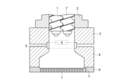
- FIG. 2 is a cross-sectional view showing an example of the vicinity of a die portion in a twin-screw extruder.
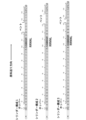
- FIG. 2 is a cross-sectional view showing the screw configuration of a twin-screw extruder used in the examples.
- 1 is a photograph of a molten resin when a die holder is opened when measuring an undissolved rate in an example.
- 4 is an image for measuring the unmelted rate of the molten resin in FIG. 3.
- FIG. 4 shows an extracted image of a portion with high brightness. This is an image binarized from the image in FIG. 5 in order to measure the area ratio of the unmelted portion.
- the raw material used in the method for producing polycarbonate resin composition pellets of the present invention is polycarbonate resin powder having a viscosity average molecular weight (Mv) of 11,000 to 27,000 and a median diameter D50 of 400 to 1,500 ⁇ m as measured by a wet light scattering method.
- the polycarbonate resin powder refers to powder forms including, for example, flakes, granules, powders, and the like.
- the viscosity average molecular weight (Mv) is preferably 12,000 or more, more preferably 13,000 or more, and is preferably 26,000 or less, more preferably 25,000 or less, and even more preferably 24,000 or less.
- the median diameter D50 of the polycarbonate resin powder is less than 400 ⁇ m, the resin temperature becomes too high and the color tone deteriorates. If it is more than 1500 ⁇ m, the resin tends to be unmelted and vent-up tends to occur.
- the median diameter D50 is preferably 450 ⁇ m or more, more preferably 500 ⁇ m or more, and is preferably 1400 ⁇ m or less, more preferably 1300 ⁇ m or less, and even more preferably 1200 ⁇ m or less.
- the particle size of the polycarbonate resin powder is the D50 value determined by a laser diffraction particle size distribution analyzer, specifically, a value measured by a light scattering wet method using a laser diffraction particle size distribution analyzer "Mastersizer 3000" manufactured by Malvern Panalytical, purified water as the dispersion medium, and a surfactant as the dispersant.
- the measurement range is 0.01-3500 ⁇ m.
- the particle size of the polycarbonate resin powder or granule can also be expressed by a particle size distribution measured according to a method in accordance with JIS K0069 (dry sieving test method), and can also be determined from the median diameter D 50 measured by this method.
- the particle size measured by this method is within the range of 400 to 1500 ⁇ m, preferably 450 to 1400 ⁇ m, and more preferably 500 to 1300 ⁇ m.
- Polycarbonate resin powder satisfying such median diameter D50 and viscosity average molecular weight can be appropriately selected and used from commercially available products.
- the polycarbonate resin powder may be 100% by mass of the polycarbonate resin raw material used as a raw material, or 50% by mass or more of the polycarbonate resin raw material used may satisfy the above viscosity average molecular weight and particle size.
- the amount of polycarbonate resin powder is preferably more than 50% by mass, more preferably more than 60% by mass, and more preferably more than 70% by mass, 80% by mass, or 85% by mass, and even more preferably more than 90% by mass or more than 95% by mass.
- polycarbonate resin examples include aromatic polycarbonate resins, aliphatic polycarbonate resins, and aromatic-aliphatic polycarbonate resins. Of these, aromatic polycarbonate resins are preferred. Specifically, aromatic polycarbonate polymers or copolymers obtained by reacting an aromatic dihydroxy compound with phosgene or a diester of carbonic acid are used.
- Aromatic dihydroxy compounds include 2,2-bis(4-hydroxyphenyl)propane (i.e., bisphenol A), 2,2-bis(3-methyl-4-hydroxyphenyl)propane (i.e., bisphenol C), tetramethylbisphenol A, ⁇ , ⁇ '-bis(4-hydroxyphenyl)-p-diisopropylbenzene, hydroquinone, resorcinol, 4,4'-dihydroxydiphenyl, etc.
- bisphenol A 2,2-bis(4-hydroxyphenyl)propane
- 2,2-bis(3-methyl-4-hydroxyphenyl)propane i.e., bisphenol C
- tetramethylbisphenol A ⁇ , ⁇ '-bis(4-hydroxyphenyl)-p-diisopropylbenzene
- hydroquinone resorcinol
- 4,4'-dihydroxydiphenyl etc.
- polycarbonate resins include polycarbonate resins that use bisphenol A as a dihydroxy compound or a combination of bisphenol A and other aromatic dihydroxy compounds, and polycarbonate resins that use bisphenol C or a combination of bisphenol C and other aromatic dihydroxy compounds (particularly bisphenol A).
- the polycarbonate resin may be a homopolymer consisting of one type of repeating unit, or a copolymer having two or more types of repeating units.
- the copolymer may be of various copolymer forms, such as a random copolymer or a block copolymer.
- the method for producing the polycarbonate resin is not particularly limited, and polycarbonate resin produced by either the phosgene method (interfacial polymerization method) or the melting method (ester exchange method) can be used.
- Polycarbonate resin produced by the interfacial polymerization method is suitable for the present invention because it is easy to obtain a polycarbonate resin with a small color tone YI and because it is in a flake form during polymerization production. It is preferable that the color tone YI is less than 2.0 using the method described below.
- the polycarbonate resin may be not only virgin raw materials, but also polycarbonate resin recycled from used products (so-called material recycled polycarbonate resin), and it is also preferable that it contains both virgin raw materials and recycled resin, and it may be made of recycled polycarbonate resin.
- material recycled polycarbonate resin used products
- the proportion of recycled polycarbonate resin in the polycarbonate resin is preferably 40 mass% or more, 50 mass% or more, 60 mass% or more, 80 mass% or more, and may be 100 mass%.
- twin-screw extruder In the manufacturing method of the present invention, a twin-screw extruder is used. Various types of twin-screw extruders can be used, and the screw rotation method may be either co-rotating or counter-rotating, but a co-intermeshing twin-screw extruder is particularly preferred. It is also preferable to provide the twin-screw extruder with a vent port that is either reduced pressure or open to the atmosphere.
- a twin-screw extruder having an ultra-high torque preferably with a maximum torque density of 16 to 20 Nm/ cm3
- the torque density of one of the screw shafts at the base of the twin-screw extruder is set to 9.0 to 17.0 Nm/ cm3
- the screw shaft torque density is defined as the torque Nm (torque applied to the root of the screw) required to drive one screw divided by the cube of the center distance of the screw shaft, and is expressed in units of Nm/ cm3 .
- the motor that drives the screw generates torque (Nm), which is transmitted to the screw shaft and performs the work of transporting and melting the polycarbonate resin.
- This torque represents the strength of the torque applied to the root of the screw shaft.
- the torque decreases as it progresses toward the tip of the screw, and the torque at the tip of the screw is 0 Nm.
- the torque generated by the motor driving the screw of the extruder is displayed on the control panel of the extruder in % units relative to the screw allowable torque of 100%. For example, in the case of TEX44 ⁇ III, 100% torque corresponds to a torque density of 17.9 Nm/cm 3 , so the torque density can be calculated from the displayed % during operation.
- the current value (A) divided by the rated current corresponds to the torque %.
- the maximum torque of TEX44 ⁇ III (the sum of the torque applied to the roots of the two screw shafts) is 2077 Nm, and the distance between the two screw shafts is 3.87 cm, so the maximum torque density of one screw (root part) is 17.9 Nm/cm 3 .
- Raw materials such as polycarbonate resin powder are fed through a feed port at the base of the extruder, where they are fed, conveyed, and preheated in the feed, conveying, and preheating section. They are then melted and kneaded in the kneading section and conveyed.
- the screw configuration is as follows: from the base of the extruder in the direction of raw material feed, the supply/conveying/preheating section is made up of a full-flight conveying screw, a kneading section, and a full-flight screw for conveying after melting.
- a vacuum vent is preferably provided in the part of the full-flight screw following the kneading section. This vacuum vent removes volatile components in the molten resin, i.e. moisture, residual solvent, volatile components of additives, etc.
- the kneading section is not particularly limited in its configuration, but it is preferable that it is configured with a length of 2.5D to 8.0D (D is the cylinder diameter) that combines two or more of the following: R kneading disk, N kneading disk, L kneading disk, L screw, seal ring, mixing screw, or rotor screw.
- This kneading section may be installed in two or more locations as long as the total length is 2.5D to 8.0D.
- the R kneading disc is also called a progressive kneading disc (hereinafter sometimes referred to as R), and usually has two or more blades, the twist angle ⁇ of which is 10 degrees to 75 degrees. By setting the blades at a predetermined angle in this way, it is possible to feed the resin and apply a strong shearing force.
- the N kneading disc is also called the orthogonal kneading disc (hereinafter sometimes referred to as N), and usually has two or more blades, with the twist angle ⁇ of the blade being 75 degrees to 105 degrees. Since the blades are installed offset by approximately 90 degrees, there is almost no force to feed the resin, but the kneading force is strong.
- the L kneading disc is also called the reverse kneading disc (hereinafter sometimes referred to as L), and usually has two or more blades with a twist angle ⁇ of -10 degrees to -75 degrees.
- the L kneading disc is an element with a pressure-increasing ability that blocks incoming resin and acts in the direction of sending back the resin that has been sent. By installing it downstream of the element that promotes kneading, it blocks the resin and exerts a strong kneading effect.
- the L screw also known as the reverse feed screw, is a screw that spirals in the opposite direction to the normal feed screw, and is an element that has the ability to block resin and increase pressure in the direction that returns the fed resin. Like the L kneading disk, it blocks resin by being installed downstream of the element that promotes kneading, and exerts a strong kneading effect.
- the above-mentioned blades are usually elliptical, with flat parts at the two vertices of the ellipse. These blades are also called disks, and each kneading disk is usually composed of 3 to 7 disks. These disks may be approximately triangular and have three vertices, which are also called three-row kneading disks. Similarly, there are R, N, and L types. These can also be used in the same way. Among the kneading disks, there are also twist kneading disks, etc., in which the vertices are twisted in the screw axial direction, and similar kneading effects can be obtained. A twist kneading disk is preferably used to efficiently melt polycarbonate resin powder particles having a median diameter D50 of 400 to 1500 ⁇ m.
- the seal ring is a ring-shaped device that is fitted to the screw, and blocks about 70 to 90% of the flow path, retaining the resin flow and increasing the resin pressure.
- L kneading by installing it downstream of the element that promotes kneading, the resin is blocked, providing a strong kneading effect.
- a mixing screw is made by cutting the crest of a screw flight, and is a single- or double-start or reverse-start screw that has a strong shear dispersion force.
- the rotor screw has elliptical (two-blade structure) or triangular rotor blades, and can generate strong shear force due to the gap (tip clearance) between the rotor and the inner wall surface of the barrel.
- R kneading disk it is preferable to combine two or more of the above kneading sections, but more preferable to combine an R kneading disk, an N kneading disk, and an L kneading disk.
- R kneading disk an R kneading disk
- N kneading disk an N kneading disk
- L kneading disk a configuration in which multiple Ns are placed after one or multiple Rs, and then an L, such as RRNNNNNNL, or a configuration such as RNNNL, is preferable.
- the torque density applied to the screw shaft is 9.0 to 17.0 Nm/ cm3
- the screw rotation speed is 400 to 800 rpm, making it possible to extrude a high output rate that has not been achieved before. If the screw rotation speed is less than 400 rpm and the torque density is less than 9.0 Nm/ cm3 , high output cannot be obtained. If the torque density exceeds 17.0 Nm/ cm3 , the screw shaft may be damaged by a small torque fluctuation. If the screw rotation speed exceeds 800 rpm, the resin temperature rises rapidly, leading to an increase in YI and a deterioration in total light transmittance. In order to produce polycarbonate resin composition pellets with excellent transparency at high output (high productivity), the screw rotation speed must be in the range of 400 to 800 rpm and the torque density must be in the range of 9.0 to 17.0 Nm/ cm3 .
- the screw shaft torque density is in the range of 9.0 to 17.0 Nm/ cm3
- the screw rotation speed is in the range of 400 to 800 rpm
- [discharge rate (kg/h) ⁇ screw rotation speed (rpm) ⁇ cube of center distance between twin screw shafts ( cm3 )] is 0.015 to 0.026 kg/h/rpm/ cm3 .
- a specific polycarbonate resin raw material is used and kneaded under the above conditions, and the unmelted portion of the polycarbonate resin composition after kneading is set to 2 to 30%, which makes it possible to significantly lower the resin temperature and suppress an increase in color tone YI.
- the screw shaft torque density is 9.0 to 17.0 Nm/ cm3 , but is preferably 9.5 Nm/ cm3 or more, more preferably 10.0 Nm/cm3 or more , even more preferably 10.5 Nm/cm3 or more , and is preferably 16.5 Nm/cm3 or less , more preferably 16.0 Nm/ cm3 or less.
- a twin-screw extruder has a die holder 4 attached via a flange 3 to the tip 2 of a cylinder that houses two screws 1, 1'.
- the die section has a breaker plate (or ring plate) 5, and a screen mesh can be installed inside the breaker plate 5 to filter out foreign matter. If a screen mesh is not used, it is common to install a ring-shaped plate called a ring plate.
- the die holder 4 is also called the die plate, and the flange 3 is also called the hinge plate.
- a die 6 with a die hole 7 is built into the die holder 4.
- the percentage of unmelted parts in the polycarbonate resin composition after kneading can be confirmed as the unmelted rate in the inside A of the flange 3 just before the die holder 4. Specifically, after melt-kneading under the above conditions, the die holder 4 of the extruder is opened by its hinge of the flange 3, and the molten resin in the inside A of the flange 3 is allowed to drip downward. When the vent is then suctioned with a vacuum, the molten part appears transparent, and the unmelted part appears cloudy. At this time, no force is applied to the resin, and the resin that comes out from inside the flange 3 is allowed to fall naturally.
- Fig. 3 is a photograph showing this state, and is a photograph of the molten resin when it is opened to measure the undissolved rate in the examples.
- the die holder 4 is pulled forward in Fig. 3 by the hinge on the side of the flange 3, and the part of the resin dripping down from the die holder 4, which is surrounded by a white dashed line in Fig. 3, is photographed to obtain an image as shown in Fig. 4.
- This image is analyzed to determine the visual area ratio of the unmelted portion from the transparent melted portion and the unmelted opaque portion, and the unmelted ratio (unmelted visual area ratio: unit: %) is measured.
- the image analysis was carried out as follows. Using a general-purpose image analysis and measurement system, "WinROOF2018” (Mitani Shoji Co., Ltd.), a monochrome image as shown in Figure 4 was created, and using the density conversion function, the threshold value was set to a density of 67 to 255 to extract high-luminance areas ( Figure 5). After that, the image was binarized to select the cloudy areas (unmelted areas) with a threshold value of 63 to 225 ( Figure 6), and the visual field area ratio of the unmelted areas was measured from this. This unmelted field area ratio is not the unmelted volume ratio "unmelted part volume/(melted part volume+unmelted part volume)".
- the melted part is transparent, and both the unmelted part on the surface and the unmelted part inside are visible. Therefore, the unmelted field area ratio is larger than the unmelted volume ratio, but in the present invention, the unmelted field area ratio measured by the above-mentioned method is used as the unmelted ratio.
- the unmelted rate is 2-30%, but is preferably 3% or more, more preferably 4% or more, and is preferably 25% or less, more preferably 20% or less.
- the resin temperature can be significantly lowered and it becomes possible to suppress an increase in the color tone YI. If the unmelted rate is less than 2%, the YI will be poor and the transparency will be insufficient, and if it exceeds 30%, venting will occur rapidly, making it easy for production to become impossible.
- Polycarbonate resin absorbs about 0.2% water in a high humidity environment.
- a solvent is used in the manufacturing process, and even if it is dried in a subsequent process, a small amount of the solvent remains. Usually, the remaining solvent is 0.1% or less. This water and remaining solvent vaporize in the high temperature/molten state in the twin-screw extruder, and the volatile components are degassed from the vacuum vent, but the more polycarbonate resin is processed, the greater the amount of volatile components. This causes an upward air current due to the large amount of volatile components in the vacuum vent, making it easy for vent-up to occur, which pushes up the molten resin.
- vent-up it is possible to further suppress it by using a vent cylinder having an opening with a screw axial length of 2.0 to 6.0D downstream of the kneading section to perform devolatilization. If it is shorter than 2.0D, devolatilization is insufficient, and vent-up is likely to occur from the upstream of the vacuum vent. If it is longer than 6.0D, the extruder becomes longer overall, the residence time becomes longer, the resin temperature increases, and the YI increases.
- the width of the opening of the vacuum vent (the length of the width perpendicular to the screw) is preferably 0.3 to 1.5D. If it is less than 0.3D, the devolatilization ability is low and vent-up is likely to occur.
- a cylinder is sometimes called a barrel, and although the name may vary depending on the extruder manufacturer, it is the same thing, and refers to the cylindrical part into which the twin screw fits.
- the cylinder diameter refers to the diameter of the cylinder where the holes do not intersect as the two cylinders on the left and right intersect.
- 1D refers to the cylinder diameter.
- the distance from the most downstream position of the vent opening to the tip of the screw be 5.0 to 10.0D. If it is shorter than this, the pressure from the die hole and mesh screen will cause the resin retention area at the tip of the screw to reach the vacuum vent, making it easy for venting to occur. In this case, venting occurs when resin rises from downstream of the screw to the vent area. If it is longer than this, the retention time will be longer, the resin temperature will rise, and YI will be more likely to increase.
- the extruded strand-like molten polycarbonate resin composition is then cooled, preferably in water, and cut into pellets.
- the shape of the extrusion die 6 is not particularly limited, and a known one may be used.
- the diameter of the die hole 7 of the discharge nozzle is usually about 2 to 5 mm, depending on the extrusion pressure and the desired size of the pellets.
- the temperature of the polycarbonate resin composition immediately after extrusion is preferably 260 to 330°C, more preferably 265 to 325°C.
- a raw material containing preferably 50% by mass or more of polycarbonate resin powder having a viscosity average molecular weight of 11,000 to 27,000 and a median diameter D50 of 400 to 1,500 ⁇ m is used, but other resins and additives may be blended in.
- Such blending components can be fed from a feed port at the base of the twin-screw extruder together with the polycarbonate resin powder or as a separate feed, or can be added from the middle of a divided kneading section.
- Preferred examples of other blending components include other resins, flame retardants such as phosphorus-based flame retardants and organometallic salt-based flame retardants, flame retardant assistants such as fluororesin (PTFE), various elastomers (impact resistance improvers), release agents, stabilizers, fillers, reinforcing agents, colorants (dyes and pigments), ultraviolet absorbers, antistatic agents, antifogging agents, antiblocking agents, flow improvers, plasticizers, dispersants, and antibacterial agents.
- flame retardants such as phosphorus-based flame retardants and organometallic salt-based flame retardants
- flame retardant assistants such as fluororesin (PTFE), various elastomers (impact resistance improvers), release agents, stabilizers, fillers, reinforcing agents, colorants (dyes and pigments), ultraviolet absorbers, antistatic agents, antifogging agents, antiblocking agents, flow improvers, plasticizers, dispersants, and antibacterial agents.
- polycarbonate resin pellets may be used.
- the size of the pellets is usually 2 to 5 mm in length and 2 to 5 mm in thickness (diameter).
- the weight is in the range of 10 to 40 mg per pellet.
- the polycarbonate resin pellets may be unused so-called virgin pellets, or recycled material (regenerated material) pellets.
- raw materials for recycled material pellets include optical disks such as CDs and DVDs, light guide plates, automobile window glass, automobile headlamp lenses, vehicle transparent parts such as windshields, containers such as water bottles, eyeglass lenses, soundproof walls, glass windows, corrugated sheets, and other building parts.
- crushed products obtained from non-conforming products, sprues, or runners during molding, or crushed, washed, separated, and recovered from these, may be repelletized.
- the polycarbonate resin composition pellets obtained by the method of the present invention have excellent transparency, and the total light transmittance (2 mm thickness) measured by transmitted light according to JIS K7361 is preferably 50% or more, more preferably 60% or more, even more preferably 65% or more, and particularly preferably 70% or more.
- the method for producing a molded article from the polycarbonate resin composition pellets obtained by the method of the present invention is not particularly limited, and molding methods generally used for polycarbonate resins, such as general injection molding, ultra-high speed injection molding, injection compression molding, multi-color injection molding, gas-assisted injection molding, molding using an insulated mold, molding using a rapid heating and cooling mold, foam molding (including supercritical fluids), insert molding, IMC (in-mold coating molding) molding, extrusion molding, sheet molding, thermoforming, rotational molding, lamination molding, press molding, etc. can be used.
- molding methods generally used for polycarbonate resins such as general injection molding, ultra-high speed injection molding, injection compression molding, multi-color injection molding, gas-assisted injection molding, molding using an insulated mold, molding using a rapid heating and cooling mold, foam molding (including supercritical fluids), insert molding, IMC (in-mold coating molding) molding, extrusion molding, sheet molding, thermoforming, rotational molding, lamination molding, press molding, etc.
- the resulting molded products can be ideally used as parts for office equipment such as printers and copiers, electrical equipment, electronic equipment, vehicles such as automobiles, homes, buildings, and other applications, and are particularly suitable for use as housings for office equipment such as printers and copiers, computers, personal computers, various mobile terminals, batteries, and other applications.
- the extruder used in the examples and comparative examples was a twin-screw extruder "TEX44 ⁇ III" manufactured by Japan Steel Works, Ltd.
- the center distance of the screw shafts was 3.87 cm, and the maximum torque (the sum of the torques applied to the roots of the two screw shafts) was 2077 Nm.
- the screw configurations used were the screw configurations shown in cylinder configurations 1 to 3 in Figure 2. All kneading sections were configured with five sets of kneading disks RRNNL. Each kneading disk had five blades and a length of 0.936D. 1D had a cylinder diameter of 47 mm.
- the cylinder configurations are cylinder configurations 1 to 3 shown in FIG.
- ⁇ Cylinder configuration 1> The cylinder position C1 was a hopper cylinder, C2 to C11 were intermediate cylinders (cylinders with no openings), C12 was a vent cylinder with a long opening (opening length 4D, opening width 1D), and C13 to C14 were intermediate cylinders.
- ⁇ Cylinder configuration 2> C1 was a hopper cylinder, C2 to C12 were intermediate cylinders, C13 was a vent cylinder with a long opening (opening length 4D, opening width 1D), and C14 was an intermediate cylinder.
- ⁇ Cylinder configuration 3> C1 was a hopper cylinder, C2 to C12 were intermediate cylinders, C13 was a normal vent cylinder (opening length 1D, opening width 1D), and C14 to C15 were intermediate cylinders.
- a 40-mesh screen mesh was installed inside the breaker plate 5.
- the die 6 used had a hole diameter of 4.5 mm, 17 holes, and a land length L of 16 mm.
- Examples 1 to 7, Comparative Examples 1 to 2 The raw material used was a polycarbonate resin powder having a viscosity average molecular weight Mv of 14,200 and a median diameter D50 of 574 ⁇ m as measured by a wet light scattering method ("H-7000" manufactured by Mitsubishi Engineering Plastics Corporation; hereinafter referred to as PC-1).
- the D50 measured by the JIS K0069 dry sieving method was 620 ⁇ m.
- Example 1 The cylinder configuration was cylinder configuration 1, and the cylinder set temperatures were 70 ° C. at cylinder position C2, 250 ° C. at C3 to C14, and 250 ° C. for the flange and die holder.
- the screw rotation speed was 700 rpm
- PC-1 was fed to the hopper cylinder of C1 at a processing rate (same as the discharge rate) of 850 kg / h
- the discharge rate / rotation speed / cube of the shaft distance was kneaded under the condition of 0.021 kg / h / rpm / cm 3.
- the screw shaft torque density was calculated from the motor torque (torque %) displayed on the control panel at this time.
- the unmelted field area rate (hereinafter referred to as the unmelted rate (%)) was determined by the image analysis described above, and is shown in Table 1.
- the feed and screw rotation were once stopped, the die holder was closed, and the operation was continued under the same conditions to extrude a strand, which was then taken up using a cooling water tank and cut with a pelletizer to obtain pellets.
- the pellets thus obtained were injection molded, and the total light transmittance and YI were determined.
- the temperature of the strand emerging from the die was measured with a thermocouple and regarded as the resin temperature.
- Total light transmittance was measured according to JIS K7361 by drying the resin composition pellets at 100°C for 5 hours, and then injection molding a three-stage plate (90 mm x 50 mm x thicknesses of 3 mm (length 20 mm), 2 mm (length 45 mm), and 1 mm (length 25 mm) from the gate side) using an injection molding machine (Japan Steel Works, Ltd., "J55-60H") at a cylinder setting temperature of 280°C, a mold temperature of 70°C, a screw rotation speed of 100 rpm, and an injection speed of 25 mm/s.
- the total light transmittance (unit: %) of the 2 mm-thick portion of the obtained three-stage plate was measured using a Nippon Denshoku Industries Co., Ltd., NDH-2000 type haze meter.
- Example 2 The experiment was carried out in the same manner as in Example 1, except that the screw rotation speed, discharge amount, and the cube of the discharge amount/rotation speed/axis distance were set as shown in Table 1.
- Example 6 The experiment was conducted in the same manner as in Example 1, except that the cylinder configuration was changed to cylinder configuration 2.
- the vacuum vent port was checked, it was confirmed that the resin was gradually rising from the region downstream of the screw.
- the strand was immediately pulled, cut with a pelletizer, and pellets were sampled in a short time.
- the vacuum vent port was blocked, and it was necessary to stop the extruder. Since the resin gradually vented up from the region downstream of the screw, it is considered that the resin was retained at the tip of the screw due to the resin pressure in the die hole and mesh, and vented up.
- Example 7 The experiment was conducted in the same manner as in Example 1, except that the cylinder configuration was changed to cylinder configuration 3.
- the vacuum vent port was checked, it was confirmed that the resin was gradually vented up from the region upstream of the screw, although only slightly.
- the strand was immediately pulled, cut with a pelletizer, and pellets were sampled in a short time. After a long period of operation, the vacuum vent port was clogged, and it was necessary to stop the extruder. Since the resin was gradually vented up from the region upstream of the screw, it is considered that a large amount of volatile components were released from the resin, and that the volatile components rose quickly in a normal vent with a narrow opening, causing the resin to vent up gradually.
- Comparative Example 1 The experiment was conducted in the same manner as in Example 1, except that the screw rotation speed, discharge rate, and the cube of discharge rate/rotation speed/axis distance were set as the conditions in Table 1.
- the unmelted rate when the die holder was opened was as high as 33%.
- venting occurred rapidly from the upstream of the screw, and the extruder had to be stopped. There was no time to sample the pellets. It is believed that there were many unmelted parts, which were blocked by the mesh, and the resin was retained in a long range at the tip of the screw, causing the rapid venting.
- Comparative Example 2 The experiment was conducted in the same manner as in Example 1, except that the screw rotation speed, discharge rate, and the cube of discharge rate/rotation speed/axis distance were set as the conditions in Table 1.
- the die holder When the die holder was opened, no unmelted parts were observed (unmelted rate: 0%). The die holder was closed, and the strand was taken out and cut to obtain pellets. The temperature of the strand was high, and the YI of the injection molded piece was also high. It is believed that the absence of unmelted parts caused the resin temperature to easily rise and the color tone to deteriorate.
- Table 1 The results are shown in Table 1 below.
- Example 8 Comparative Examples 3 to 4
- the raw material used was a polycarbonate resin powder having a viscosity average molecular weight Mv of 21,500 and a median diameter D50 of 1,060 ⁇ m as measured by a wet light scattering method (manufactured by Mitsubishi Engineering Plastics Corporation, "S-3000"; hereinafter referred to as PC-2).
- the D50 measured by the JIS K0069 dry sieving method was 1,150 ⁇ m.
- Example 8 The experiment was carried out in the same manner as in Example 1, except that the polycarbonate PC-2 was used instead of the polycarbonate PC-1.
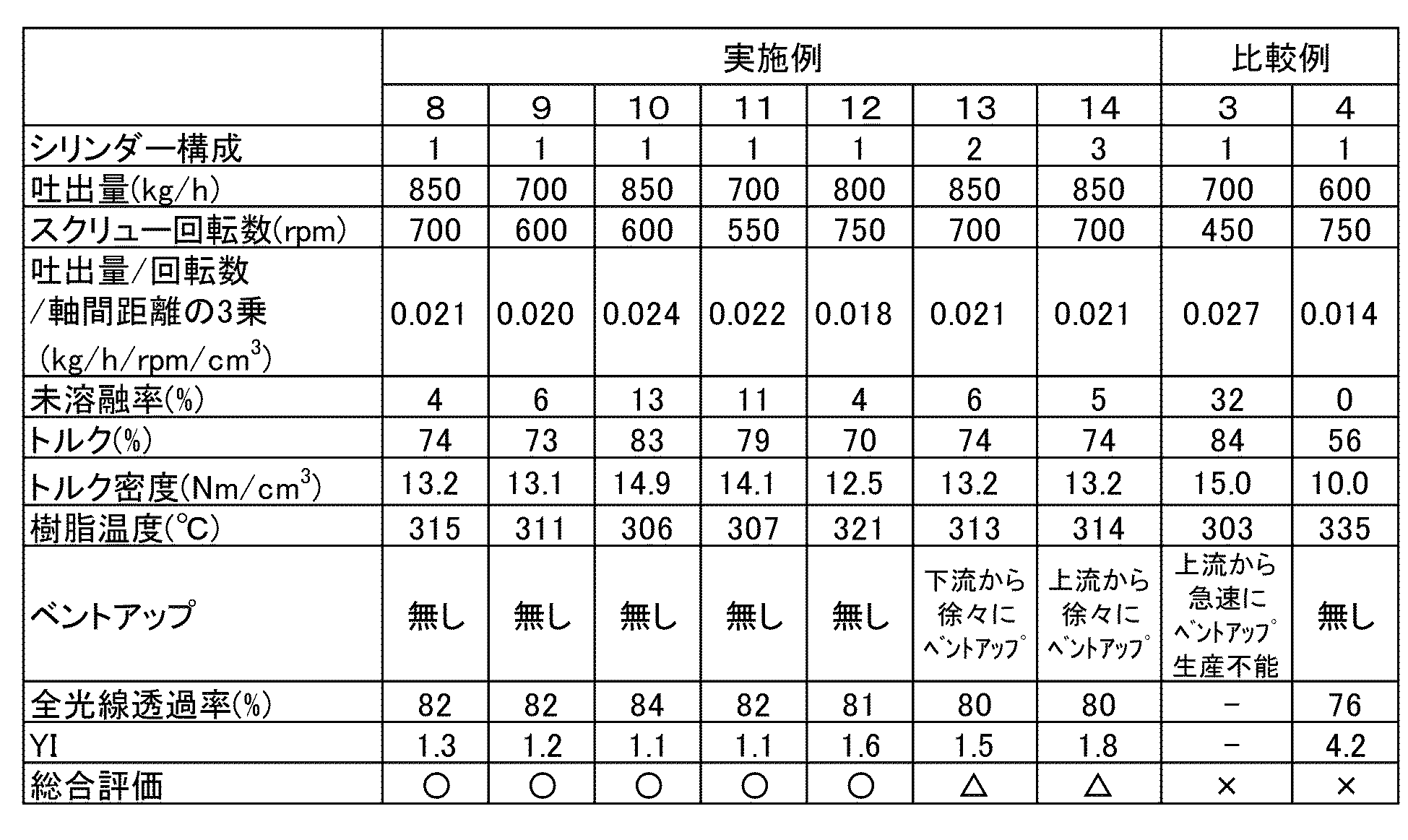
- Examples 9 to 12 The experiment was conducted in the same manner as in Example 8, except that the screw rotation speed, discharge amount, and the cube of the discharge amount/rotation speed/axis distance were set as shown in Table 2.
- Example 13 The experiment was conducted in the same manner as in Example 8, except that the cylinder configuration was changed to cylinder configuration 2.
- the vacuum vent port was checked, it was confirmed that the resin was gradually rising from the region downstream of the screw.
- the strand was immediately pulled, cut with a pelletizer, and pellets were sampled in a short time.
- the vacuum vent port was blocked, and it was necessary to stop the extruder. Since the resin gradually vented from the region downstream of the screw, it is considered that the resin was retained at the tip of the screw due to the resin pressure in the die hole and mesh, and vented up.
- Example 14 The experiment was conducted in the same manner as in Example 8, except that the cylinder configuration was changed to cylinder configuration 3.
- the vacuum vent port was checked, it was confirmed that the resin was gradually vented up from the region upstream of the screw.
- the strand was immediately pulled, cut with a pelletizer, and pellets were sampled in a short time.
- the vacuum vent port was clogged, and it was necessary to stop the extruder. Since the resin was gradually vented up from the region upstream of the screw, it is considered that there was a lot of volatile components from the resin, and the volatile components rose quickly in a normal vent with a narrow opening, causing the resin to vent up gradually.
- Comparative Example 3 The experiment was conducted in the same manner as in Example 8, except that the screw rotation speed, discharge rate, and the cube of discharge rate/rotation speed/axis distance were set as the conditions shown in Table 2.
- the unmelted rate when the die holder was opened was as high as 32%.
- venting occurred rapidly from the upstream of the screw, and the extruder had to be stopped. There was no time to sample the pellets. It is believed that there were many unmelted parts, which were blocked by the mesh, and the resin was retained in a long range at the tip of the screw, causing the rapid venting.
- Comparative Example 4 The experiment was conducted in the same manner as in Example 8, except that the screw rotation speed, discharge rate, and the cube of the discharge rate/rotation speed/axis distance were set as the conditions in Table 2.
- the die holder was opened, no unmelted parts were observed (unmelted rate: 0%).
- the die holder was closed, and the strand was taken out and cut to obtain pellets.
- the temperature of the strand was high, and the YI of the injection molded piece was also high. It is believed that the absence of unmelted parts caused the resin temperature to easily rise and the color tone to deteriorate.
- Table 2 The results are shown in Table 2 below.
- Example 15 The raw material was a mixture of 80% by mass of PC-2 and 20% by mass of pellets of polycarbonate resin having a viscosity average molecular weight of 20,800 ("M7020IR” manufactured by Mitsubishi Engineering Plastics Corporation) (pellet diameter: 3 mm, pellet length: 3 mm, average weight: 20 mg/piece; hereinafter referred to as PC-3).
- PC-3 a viscosity average molecular weight of 20,800
- Example 15 The experiment was conducted in the same manner as in Example 1, except that the polycarbonate resin PC-1 was changed to 80% by mass (680 kg/h) of PC-2 and 20% by mass (170 kg/h) of PC-3.
- Examples 16 to 19 The experiment was conducted in the same manner as in Example 15, except that the screw rotation speed, discharge amount, and the cube of the discharge amount/rotation speed/axis distance were set as shown in Table 3.
- Example 20 The experiment was conducted in the same manner as in Example 15, except that the cylinder configuration was changed to cylinder configuration 2.
- the vacuum vent port was checked, it was confirmed that the resin was gradually rising from the region downstream of the screw.
- the strand was immediately pulled, cut with a pelletizer, and pellets were sampled in a short time.
- the vacuum vent port was blocked and it was necessary to stop the extruder. Since the resin gradually vented up from the region downstream of the screw, it is thought that the resin was retained at the tip of the screw due to the resin pressure in the die hole and mesh, causing the resin to vent up.
- Example 21 The experiment was conducted in the same manner as in Example 15, except that the cylinder configuration was changed to cylinder configuration 3.
- the vacuum vent port was checked, it was confirmed that the resin was gradually vented up from the region upstream of the screw.
- the strand was immediately pulled, cut with a pelletizer, and pellets were sampled in a short time.
- the vacuum vent port was clogged, and it was necessary to stop the extruder. Since the resin was gradually vented up from the region upstream of the screw, it is considered that there was a lot of volatile components from the resin, and the volatile components rose quickly in a normal vent with a narrow opening, so the venting was gradual.
- Comparative Example 5 The experiment was conducted in the same manner as in Example 15, except that the screw rotation speed, discharge rate, and the cube of discharge rate/rotation speed/axis distance were set as the conditions in Table 3.
- the unmelted rate when the die holder was opened was as high as 36%.
- venting occurred rapidly from the upstream of the screw, and the extruder had to be stopped.
- Comparative Example 6 The experiment was conducted in the same manner as in Example 15, except that the screw rotation speed, discharge rate, and the cube of discharge rate/rotation speed/axis distance were set as the conditions in Table 3.
- the die holder was opened, no unmelted parts were observed (unmelted rate: 0%).
- the die holder was closed, and the strand was taken out and cut to obtain pellets.
- the temperature of the strand was high, and the YI of the injection molded piece was also high. It is believed that the absence of unmelted parts caused the resin temperature to easily rise and the color tone to deteriorate.
- Comparative Example 7 The experiment was conducted in the same manner as in Example 19, except that 100% by mass of PC-3 was used as the raw material.
- the unmelted rate when the die holder was opened was as high as 35%.
- Table 3 The results are shown in Table 3 below.
- the method of the present invention uses an ultra-high torque twin-screw extruder to produce polycarbonate resin composition pellets with excellent transparency with high productivity and more stability than conventional methods, making it highly applicable in industry.
Landscapes
- Engineering & Computer Science (AREA)
- Mechanical Engineering (AREA)
- Processing And Handling Of Plastics And Other Materials For Molding In General (AREA)
Abstract
Description
ポリカーボネート樹脂組成物ペレットは通常、二軸押出機により製造され、二軸押出機は生産能力の向上のため、長年、可塑化能力、混練能力の向上が希求されてきた。そして、最近になり最大トルク密度が18Nm/cm3に達するような超高トルクの押出機(例えば、日本製鋼所社製「TEXαIII」、芝浦機械社製「TEM-SX」等)が開発され、これまでにない高トルク領域での生産が可能となった。また、高トルク化によりスクリュー回転数を従来以上に上げることが可能となり、高エネルギー領域(高トルク密度且つ高スクリュー回転数)での運転が可能となり、それにより、従来では考えられなかった高い吐出量を得ることが可能となってきた。
スクリューに沿ったトルク密度は押出機の根本が最も高く、このトルクは樹脂の溶融混練、搬送等に使われ、スクリュー先端に行くほど小さくなり、先端では0となる。特許文献1ではガラス繊維混練部の逆送りスクリューエレメントでのトルク密度の記載があるが、この部分でもスクリュー軸トルク密度はかなり小さく、3Nm/cm3以下と考えられる。
本発明の目的(課題)は、このような課題に鑑みてなされたもので、超高トルク二軸押出機を用いた高エネルギー領域において、樹脂温度を下げ、色調YIの悪化を防ぐポリカーボネート樹脂ペレットを製造する方法を提供することにある。
メジアン径D50が400~1500μmというようなポリカーボネート樹脂粉粒体のガラス転移温度は140℃ほどである。また界面法で製造されるポリカーボネート樹脂は部分的に結晶構造を有するといわれているが、その融点は200℃程であり、融解する際に30J/g程の融解熱を必要するといわれている。つまり、半溶融の状態では周囲の溶融ポリカーボネートに比べ、かなり温度が低く、溶ける際に周囲から多くの熱を吸収する。要するにお湯の中に氷を入れると、急速にお湯の温度が低下するようなものである。この未溶融部が少ないと周囲の溶融ポリカーボネートの温度を下げることができない。また未溶融部分が多すぎるとダイやメッシュ部で未溶融が堆積し、樹脂が流れず、ベントアップを引き起こす。未溶融率が2~30%であれば、フランジより先のブレーカープレートでの剪断、ダイホルダでの滞留、その先のダイ穴での強い縮流と剪断により、未溶融部は溶融する。あるいは微小に残った未溶融部ではストランドが切れることはない。
本発明は、以下のポリカーボネート樹脂組成物ペレットの製造方法に関する。
1本のスクリュー根本に掛かるスクリュー軸トルク密度が9.0~17.0Nm/cm3の範囲、スクリュー回転数は400~800rpmの範囲で、吐出量(kg/h)÷スクリュー回転数(rpm)÷二軸のスクリュー軸の芯間距離の3乗(cm3)が0.015~0.026kg/h/rpm/cm3の条件で混練し、ダイホルダ手前のフランジ部での未溶融率を2~30%の範囲とし、ダイから押し出したストランドを引き取りペレット化することを特徴とするポリカーボネート樹脂組成物ペレットの製造方法。
2.混練部の下流側にスクリュー軸方向で長さが2.0~6.0D(Dはシリンダー径)の開口部を有するベントを使用し真空脱揮し、ベント開口部の最下流位置からスクリュー先端までの距離を5.0~10.0Dとする上記1に記載の製造方法。
3.ダイから出た直後のストランドの温度が260~330℃の範囲である上記1または2に記載の製造方法。
4.得られたポリカーボネート樹脂組成物ペレットから、JIS K7361により透過光で求めた全光線透過率が50%以上である上記1~3のいずれかに記載の製造方法。
なお、ポリカーボネート樹脂粉粒体としては、例えばフレーク状、グラニュール状、パウダー状などを含む粉粒体形状のものをいう。
ポリカーボネート樹脂としては、芳香族ポリカーボネート樹脂、脂肪族ポリカーボネート樹脂、芳香族-脂肪族ポリカーボネート樹脂が挙げられるが、好ましくは、芳香族ポリカーボネート樹脂であり、具体的には、芳香族ジヒドロキシ化合物をホスゲン又は炭酸のジエステルと反応させることによって得られる芳香族ポリカーボネート重合体又は共重合体が用いられる。
[η]=1.23×10⁻⁴Mv0.83
スクリュー軸トルク密度とは、スクリュー1本当りを駆動するのに必要なトルクNm(スクリューの根本部分に掛かるトルク)をスクリュー軸の芯間距離の3乗で除した値として定義され、単位はNm/cm3となる。大きさの異なる押出機を用いた押出であっても、このトルク密度の値が同じであれば、単位体積当たりに樹脂に掛かるトルクは同じとなる。スクリューを駆動するモーターがトルク(Nm)を発生し、スクリュー軸に伝わり、ポリカーボネート樹脂の搬送、溶融、の仕事をする。このトルクはスクリュー軸の根本に掛かるトルクの強さを表す。そして、トルクは、スクリューの先端に向けて進むにつれその値は減少し、スクリューの先端でのトルクは0Nmとなる。
押出機のスクリューを駆動するモーターが発生するトルクは、押出機の制御盤にスクリュー許容トルク100%に対する%単位で表示される。例えば、TEX44αIIIの場合、トルク100%はトルク密度17.9Nm/cm3に相当するので、運転時の表示%からトルク密度を算出することができる。また、一般のVVVFインバータ制御では定トルク領域では電流値(A)を定格電流で割った値がトルク%に一致する。TEX44αIIIの最大トルク(2本のスクリュー軸の根本に掛かるトルクの合計)は2077Nmであり、2本のスクリュー軸間は3.87cmなので、スクリュー1本の最大トルク密度(根本部)は17.9Nm/cm3となる。
Nニーディングディスクは、直交ニーディングディスク(以下Nと称することもある)とも呼ばれ、通常羽根が2枚以上で、かつ羽根のねじれ角度Θが75度から105度である。羽根が略90度ずらして設置されているために樹脂を送る力は殆どないが混練力は強い。
Lニーディングディスクは、逆送りニーディングディスク(以下Lと称することもある)とも呼ばれ、通常羽根が2枚以上でその羽根のねじれ角度Θは-10度から-75度である。Lニーディングディスクは送られてくる樹脂を堰き止めたり、送られた樹脂を送り戻す方向に働く昇圧能力のあるエレメントである。混練を促進するエレメントの下流側に設けることにより樹脂を堰き止め、強力な混練効果を発揮させるものである。
Lスクリューは、逆送りスクリューともよばれ、通常の送りスクリューに対して、反対の方向に螺旋しているスクリューであり、樹脂を堰き止めたり、送られた樹脂を戻す方向に昇圧能力のあるエレメントである。Lニーディングディスクと同じく、混練を促進するエレメントの下流側に設けることにより樹脂を堰き止め、強力な混練効果を発揮させるものである。
メジアン径D50が400~1500μmのポリカーボネート樹脂粉粒体を効率的に溶融するにはツイストニーディングディスクが好適に用いられる。
ミキシングスクリューは、スクリューフライトの山の部分を削ってできたものであり、一条あるいは二条の送り、あるいは逆送りスクリューであって、強い剪断分散力を有するエレメントである。順送り切欠き型ミキシングスクリュー、逆送り切欠き型ミキシングスクリューがある。
ロータスクリューは、楕円形状(2翼構造)もしくは三角形状のロータ翼を形成しているもので、ロータとバレル内壁面間の隙間(チップクリアランス)により強力なせん断力を発現できる。
[吐出量(kg/h)÷スクリュー回転数(rpm)÷二軸のスクリュー軸の芯間距離の3乗(cm3)]は、好ましくは0.016~0.025kg/h/rpm/cm3であり、より好ましくは0.017~0.024kg/h/rpm/cm3である。
この画像を画像解析して、透明な溶融部と未溶融の白濁部とから、未溶融部の視野面積率を求めて、未溶融率(未溶融視野面積率:単位は%)を測定する。
汎用の画像解析計測システムである「WinROOF2018」(三谷商事社製)を用いて、図4にあるようなモノクロ画像とし、濃度変換機能を用いて、閾値を濃度67~255として輝度の高い部分を抽出し(図5)、その後、閾値63~225で白濁部(未溶融部)を選択するように二値化し(図6)、これから未溶融部の視野面積率を測定した。
この未溶融視野面積率は、未溶融体積率「未溶融部体積/(溶融部体積+未溶融部体積)」ではない。溶融部は透明であり、表層の未溶融部も内部の未溶融部も見える。従って、未溶融体積率より未溶融視野面積率は大きな値となるが、本発明では未溶融率として、上記した方法で測定する未溶融視野面積率を用いる。
シリンダーは、場合によりバレルと呼ばれることもあり、押出機メーカーにより呼称は変わるが同じものであり、二軸スクリューが入る筒状のパーツをいう。シリンダー直径とはシリンダーに左右2個の円筒が交わるように空いた穴の交わらない部分の円筒の直径をいう。ここでいう1Dとはシリンダー直径のことをいう。
押出ダイ6の形状は特に制限はなく、公知のものが使用される。吐出ノズルのダイ穴7の直径は、押出し圧、所望するペレットの寸法にもよるが、通常2~5mm程度である。押し出された直後のポリカーボネート樹脂組成物の温度は、好ましくは260~330℃、より好ましくは265~325℃である。
他の配合成分としては、他の樹脂、リン系難燃剤や有機金属塩系難燃剤などの難燃剤、フッ素樹脂(PTFE)等の難燃助剤、各種エラストマー(耐衝撃性改良剤)、離型剤、安定剤、フィラー(充填材)、強化剤、着色材(染顔料)、紫外線吸収剤、帯電防止剤、防曇剤、アンチブロッキング剤、流動性改良剤、可塑剤、分散剤、抗菌剤等が好ましく挙げられる。
ポリカーボネート樹脂ペレットは、未使用のいわゆるバージンのペレットであってもよいし、リサイクル材(再生材)ペレットであってもよい。リサイクル材ペレットの原料としては、例えばCDやDVD等の光学ディスク、導光板、自動車窓ガラスや自動車ヘッドランプレンズ、風防などの車両透明部材、水ボトルなどの容器、メガネレンズ、防音壁やガラス窓、波板などの建築部材などが好ましく挙げられる。また、成形時の不適合品、スプルーまたはランナーなどから得られた粉砕品、これらを粉砕、洗浄、分離回収したものをリペレットしたものであってもよい。
使用したスクリュー構成は、図2のシリンダー構成1~3に示すスクリュー構成とした。混練部はいずれもニーディングディスクRRNNLの5組構成とした。各二―ディングディスクとしては5枚羽根からなる、長さ0.936Dのものを使用した。1Dはシリンダー直径47mmである。
<シリンダー構成1>
シリンダー位置C1にホッパーシリンダー、C2~C11を中間シリンダー(開口のないシリンダー)、C12を開口部の長いベントシリンダー(開口長さ4D、開口幅1D)、C13~C14を中間シリンダーとした。
<シリンダー構成2>
C1をホッパーシリンダー、C2~C12を中間シリンダー、C13を開口部の長いベントシリンダー(開口長さ4D、開口幅1D)、C14を中間シリンダーとした。
<シリンダー構成3>
C1をホッパーシリンダー、C2~C12を中間シリンダー、C13を通常のベントシリンダー(開口長さ1D、開口幅1D)、C14~C15を中間シリンダーとした。
使用した原料は、粘度平均分子量Mv=14200、光散乱湿式法によるメジアン径D50が574μmのポリカーボネート樹脂粉粒体(三菱エンジニアリングプラスチックス社製「H-7000」。以下、PC-1と称する。)を使用した。JIS K0069乾式ふるい分け法で測定したD50は620μmであった。
シリンダー構成をシリンダー構成1とし、シリンダー設定温度はシリンダー位置C2を70℃、C3~C14を250℃、フランジ、ダイホルダを250℃とした。スクリュー回転数を700回転とし、PC-1を処理量(吐出量に同じ。)850kg/hでC1のホッパーシリンダーにフィードし、吐出量/回転数/軸間距離の3乗を0.021kg/h/rpm/cm3の条件で混練した。この時のモータートルク(制御盤に表示されるトルク%)からスクリュー軸トルク密度を求めた。フランジ3のヒンジでダイホルダ4を開放し、真空に吸引すると、ダイホルダ4手前のフランジ3内で溶融した透明のポリカーボネート樹脂の中に、未溶融の白濁したポリカーボネート樹脂が見られた。この溶融及び未溶融のポリカーボネート樹脂は自然落下し、下方に設置した水を張ったバットに溜まるので、10kg程溜まったらその都度取り除いた。開放したダイホルダからは2本のスクリュー先端が見られ、その部分を写真撮影し、拡大し、前述した画像解析により未溶融視野面積率(以下、未溶融率(%)と称する)を求め、表1に記載した。
一旦フィードとスクリュー回転を止め、ダイホルダを閉め、同条件で運転し、ストランドを押出、冷却水槽を用い、ストランドを引き取り、ペレタイザーでカットし、ペレットを得た。
得られたペレットを射出成形し、全光線透過率とYIを求めた。ダイから出てきたストランドの温度を熱電対で温度測定し、樹脂温度とした。
〇:2mm厚で測定のYIが2.0未満であり、生産上の問題もない。
△:2mm厚で測定のYIが2.0未満であるが、連続生産が困難。
×:2mm厚で測定のYIが2.0以上、または生産不能。
これらの結果を表1に記載した。
スクリュー回転数、吐出量、及び吐出量/回転数/軸間距離の3乗を表1に記載した通りとした以外は実施例1と同様に実験した。
シリンダー構成をシリンダー構成2にした以外は、実施例1と同様に実験した。真空ベント口を確認すると、スクリュー下流の領域から僅かながら徐々に樹脂が上がってくるベントアップが確認された。すぐさまストランドを引き、ペレタイザーでカットし、短時間でペレットをサンプリングした。長時間の運転では真空ベント口が閉塞し、押出機を止める必要があった。スクリュー下流の領域から徐々にベントアップしたことから、ダイ穴やメッシュでの樹脂圧により、スクリュー先端に樹脂が滞留し、ベントアップしたと考えられる。
シリンダー構成をシリンダー構成3にした以外は、実施例1と同様に実験した。真空ベント口を確認すると、スクリュー上流の領域から僅かながら徐々に樹脂が上がってくるベントアップが確認された。すぐさまストランドを引き、ペレタイザーでカットし、短時間でペレットをサンプリングした。長時間の運転では真空ベント口が閉塞し、押出機を止める必要があった。スクリュー上流の領域から徐々にベントアップしたことから、樹脂からの揮発成分が多く、通常の開口の狭いベントでは揮発成分の上昇速度が速く徐々にベントアップしたと考えられる。
スクリュー回転数、吐出量、及び吐出量/回転数/軸間距離の3乗を表1に記載の条件とした以外は、実施例1と同様に実験した。ダイホルダ開放時の未溶融率は33%と高かった。ダイホルダを閉めて、ストランドを引き出すと、スクリューの上流から急速にベントアップが発生し、押出機を停止せざるを得なかった。ペレットのサンプリングの時間もなかった。未溶融部が多く、メッシュでそれらが閉塞し、スクリュー先端の長い範囲で樹脂が滞留し、急速なベントアップが発生したと考えられる。
スクリュー回転数、吐出量、及び吐出量/回転数/軸間距離の3乗を表1に記載の条件とした以外は、実施例1と同様に実験した。ダイホルダ開放時に確認したが未溶融は見られなかった(未溶融率0%)。ダイホルダを閉めストランドを引き取り、カットし、ペレットを得た。ストランドの温度は高く、射出成型片のYIも高かった。未溶融部がないことにより、容易に樹脂温度が上昇し、色調が悪化したと考えられる。
以上の結果を、以下の表1に示す。

使用した原料は、粘度平均分子量Mv=21500、光散乱湿式法によるメジアン径D50が1060μmのポリカーボネート樹脂粉粒体(三菱エンジニアリングプラスチックス社製「S-3000」。以下、PC-2と称する。)を使用した。JIS K0069乾式ふるい分け法で測定したD50は1150μmであった。
実施例8
実施例1において、ポリカーボネートPC-1をPC-2にした以外は実施例1と同様に実験した。
スクリュー回転数、吐出量、及び吐出量/回転数/軸間距離の3乗を表2に記載した通りとした以外は、実施例8と同様に実験した。
シリンダー構成をシリンダー構成2にした以外は実施例8と同様に実験した。真空ベント口を確認すると、スクリュー下流の領域から僅かながら徐々に樹脂が上がってくるベントアップが確認された。すぐさまストランドを引き、ペレタイザーでカットし、短時間でペレットをサンプリングした。長時間の運転では真空ベント口が閉塞し、押出機を止める必要があった。スクリュー下流の領域から徐々にベントアップしたことから、ダイ穴やメッシュでの樹脂圧により、スクリュー先端に樹脂が滞留し、ベントアップしたと考えられる。
シリンダー構成をシリンダー構成3にした以外は実施例8と同様に実験した。真空ベント口を確認すると、スクリュー上流の領域から僅かながら徐々に樹脂が上がってくるベントアップが確認された。すぐさまストランドを引き、ペレタイザーでカットし、短時間でペレットをサンプリングした。長時間の運転では真空ベント口が閉塞し、押出機を止める必要があった。スクリュー上流の領域から徐々にベントアップしたことから、樹脂からの揮発成分が多く、通常の開口の狭いベントでは揮発成分の上昇速度が速く徐々にベントアップしたと考えられる。
スクリュー回転数、吐出量、及び吐出量/回転数/軸間距離の3乗を表2に記載の条件とした以外は実施例8と同様に実験した。ダイホルダ開放時の未溶融率は32%と高かった。ダイホルダを閉めて、ストランドを引き出すと、スクリューの上流から急速にベントアップが発生し、押出機を停止せざるを得なかった。ペレットのサンプリングの時間もなかった。未溶融部が多く、メッシュでそれらが閉塞し、スクリュー先端の長い範囲で樹脂が滞留し、急速なベントアップが発生したと考えられる。
スクリュー回転数、吐出量、及び吐出量/回転数/軸間距離の3乗を表2に記載の条件とした以外は実施例8と同様に実験した。ダイホルダ開放時に確認したが未溶融は見られなかった(未溶融率0%)。ダイホルダを閉めストランドを引き取り、カットし、ペレットを得た。ストランドの温度は高く、射出成型片のYIも高かった。未溶融部がないことにより、容易に樹脂温度が上昇し、色調が悪化したと考えられる。
以上の結果を以下の表2に記載した。
原料は、PC-2の80質量%に、粘度平均分子量が20800のポリカーボネート樹脂(三菱エンジニアリングプラスチックス社製「M7020IR」)のペレット(ペレット径3mm、ペレット長さ3mm、平均重量20mg/個。以下、PC-3という。)を20質量%の割合で混合して使用した。
実施例15
ポリカーボネート樹脂PC-1を、PC-2を80質量%(680kg/h)、PC-3を20質量%(170kg/h)とした以外は実施例1と同様に実験した。
スクリュー回転数、吐出量、及び吐出量/回転数/軸間距離の3乗を表3に記載した通りとした以外は、実施例15と同様に実験した。
シリンダー構成をシリンダー構成2にした以外は実施例15と同様に実験した。真空ベント口を確認すると、スクリュー下流の領域から僅かながら徐々に樹脂が上がってくるベントアップが確認された。すぐさまストランドを引き、ペレタイザーでカットし、短時間でペレットをサンプリングした。長時間の運転では真空ベント口が閉塞し、押出機を止める必要があった。スクリュー下流の領域から徐々にベントアップしたことから、ダイ穴やメッシュでの樹脂圧により、スクリュー先端に樹脂が滞留し、ベントアップしたと考えられる。
シリンダー構成をシリンダー構成3にした以外は実施例15と同様に実験した。真空ベント口を確認すると、スクリュー上流の領域から僅かながら徐々に樹脂が上がってくるベントアップが確認された。すぐさまストランドを引き、ペレタイザーでカットし、短時間でペレットをサンプリングした。長時間の運転では真空ベント口が閉塞し、押出機を止める必要があった。スクリュー上流の領域から徐々にベントアップしたことから、樹脂からの揮発成分が多く、通常の開口の狭いベントでは揮発成分の上昇速度が速く徐々にベントアップしたと考えられる。
スクリュー回転数、吐出量、及び吐出量/回転数/軸間距離の3乗を表3に記載の条件とした以外は、実施例15と同様に実験した。ダイホルダ開放時の未溶融率は36%と高かった。ダイホルダを閉めて、ストランドを引き出すと、スクリューの上流から急速にベントアップが発生し、押出機を停止せざるを得なかった。ペットのサンプリングの時間もなかった。未溶融部が多く、メッシュでそれらが閉塞し、スクリュー先端の長い範囲で樹脂が滞留し、急速なベントアップが発生したと考えられる。
スクリュー回転数、吐出量、及び吐出量/回転数/軸間距離の3乗を表3に記載の条件とした以外は、実施例15と同様に実験した。ダイホルダ開放時に確認したが未溶融は見られなかった(未溶融率0%)。ダイホルダを閉めストランドを引き取り、カットし、ペレットを得た。ストランドの温度は高く、射出成型片のYIも高かった。未溶融部がないことにより、容易に樹脂温度が上昇し、色調が悪化したと考えられる。
原料としてPC-3を100質量%使用したこと以外は、実施例19と同様に実験した。ダイホルダ開放時の未溶融率は35%と高かった。ダイホルダを閉めて、ストランドを引き出すと、スクリューの上流から急速にベントアップが発生し、押出機を停止せざるを得なかった。ペットのサンプリングの時間もなかった。未溶融部が多く、メッシュでそれらが閉塞し、スクリュー先端の長い範囲で樹脂が滞留し、急速なベントアップが発生したと考えられ、ペレットは溶融し難いことがわかる。
以上の結果を以下の表3に記載した。

2:押出機のシリンダー先端部
3:フランジ
4:ダイホルダ
5:ブレーカープレート
6:ダイ
7:ダイ穴
A:フランジ3内の樹脂の未溶融率測定部
Claims (4)
- 粘度平均分子量が11000~27000、光散乱湿式法によるメジアン径D50が400~1500μmのポリカーボネート樹脂粉粒体を原料とし、二軸押出機によりポリカーボネート樹脂組成物ペレットを製造する方法であって、
1本のスクリュー根本に掛かるスクリュー軸トルク密度が9.0~17.0Nm/cm3の範囲、スクリュー回転数は400~800rpmの範囲で、吐出量(kg/h)÷スクリュー回転数(rpm)÷二軸のスクリュー軸の芯間距離の3乗(cm3)が0.015~0.026kg/h/rpm/cm3の条件で混練し、ダイホルダ手前のフランジ部での未溶融率を2~30%の範囲とし、ダイから押し出したストランドを引き取りペレット化することを特徴とするポリカーボネート樹脂組成物ペレットの製造方法。 - 混練部の下流側にスクリュー軸方向で長さが2.0~6.0D(Dはシリンダー径)の開口部を有するベントを使用し真空脱揮し、ベント開口部の最下流位置からスクリュー先端までの距離を5.0~10.0Dとする請求項1に記載の製造方法。
- ダイから出た直後のストランドの温度が260~330℃の範囲である請求項1または2に記載の製造方法。
- 得られたポリカーボネート樹脂組成物ペレットから、JIS K7361により透過光で求めた全光線透過率が50%以上である請求項1~3のいずれかに記載の製造方法。
Priority Applications (3)
| Application Number | Priority Date | Filing Date | Title |
|---|---|---|---|
| JP2024568815A JP7652997B1 (ja) | 2023-06-28 | 2024-06-11 | ポリカーボネート樹脂組成物ペレットの製造方法 |
| CN202480042451.3A CN121548489A (zh) | 2023-06-28 | 2024-06-11 | 聚碳酸酯树脂组合物粒料的制造方法 |
| EP24831656.4A EP4737085A1 (en) | 2023-06-28 | 2024-06-11 | Method for producing polycarbonate resin composition pellet |
Applications Claiming Priority (2)
| Application Number | Priority Date | Filing Date | Title |
|---|---|---|---|
| JP2023105976 | 2023-06-28 | ||
| JP2023-105976 | 2023-06-28 |
Publications (1)
| Publication Number | Publication Date |
|---|---|
| WO2025004789A1 true WO2025004789A1 (ja) | 2025-01-02 |
Family
ID=93938832
Family Applications (1)
| Application Number | Title | Priority Date | Filing Date |
|---|---|---|---|
| PCT/JP2024/021180 Ceased WO2025004789A1 (ja) | 2023-06-28 | 2024-06-11 | ポリカーボネート樹脂組成物ペレットの製造方法 |
Country Status (4)
| Country | Link |
|---|---|
| EP (1) | EP4737085A1 (ja) |
| JP (1) | JP7652997B1 (ja) |
| CN (1) | CN121548489A (ja) |
| WO (1) | WO2025004789A1 (ja) |
Citations (5)
| Publication number | Priority date | Publication date | Assignee | Title |
|---|---|---|---|---|
| JPH0966524A (ja) * | 1995-06-20 | 1997-03-11 | Mitsubishi Gas Chem Co Inc | ポリカーボネート樹脂ペレットの製造法 |
| JP2003073484A (ja) * | 2001-09-03 | 2003-03-12 | Asahi Kasei Corp | 難燃性ポリカーボネート樹脂組成物の製造方法 |
| JP2012213997A (ja) | 2011-04-01 | 2012-11-08 | Polyplastics Co | ガラス繊維強化熱可塑性樹脂組成物ペレットの製造方法 |
| JP2020040356A (ja) * | 2018-09-13 | 2020-03-19 | 三菱エンジニアリングプラスチックス株式会社 | 樹脂ペレットの製造方法 |
| WO2023089929A1 (ja) * | 2021-11-16 | 2023-05-25 | 三菱エンジニアリングプラスチックス株式会社 | 難燃性ポリカーボネート樹脂組成物ペレットの製造方法 |
-
2024
- 2024-06-11 CN CN202480042451.3A patent/CN121548489A/zh active Pending
- 2024-06-11 JP JP2024568815A patent/JP7652997B1/ja active Active
- 2024-06-11 WO PCT/JP2024/021180 patent/WO2025004789A1/ja not_active Ceased
- 2024-06-11 EP EP24831656.4A patent/EP4737085A1/en active Pending
Patent Citations (5)
| Publication number | Priority date | Publication date | Assignee | Title |
|---|---|---|---|---|
| JPH0966524A (ja) * | 1995-06-20 | 1997-03-11 | Mitsubishi Gas Chem Co Inc | ポリカーボネート樹脂ペレットの製造法 |
| JP2003073484A (ja) * | 2001-09-03 | 2003-03-12 | Asahi Kasei Corp | 難燃性ポリカーボネート樹脂組成物の製造方法 |
| JP2012213997A (ja) | 2011-04-01 | 2012-11-08 | Polyplastics Co | ガラス繊維強化熱可塑性樹脂組成物ペレットの製造方法 |
| JP2020040356A (ja) * | 2018-09-13 | 2020-03-19 | 三菱エンジニアリングプラスチックス株式会社 | 樹脂ペレットの製造方法 |
| WO2023089929A1 (ja) * | 2021-11-16 | 2023-05-25 | 三菱エンジニアリングプラスチックス株式会社 | 難燃性ポリカーボネート樹脂組成物ペレットの製造方法 |
Also Published As
| Publication number | Publication date |
|---|---|
| EP4737085A1 (en) | 2026-05-06 |
| JPWO2025004789A1 (ja) | 2025-01-02 |
| JP7652997B1 (ja) | 2025-03-27 |
| CN121548489A (zh) | 2026-02-17 |
Similar Documents
| Publication | Publication Date | Title |
|---|---|---|
| TWI885142B (zh) | 阻燃性聚碳酸酯樹脂組成物丸粒的製造方法 | |
| EP3019548B1 (en) | Process for the manufacturing of abs-molding compositions | |
| JP6328586B2 (ja) | ポリカーボネート樹脂組成物の製造方法 | |
| JP2018183933A (ja) | ポリカーボネート樹脂組成物の製造方法 | |
| EP0415357A2 (en) | Extrudable polyvinyl alcohol compositions | |
| JP7652997B1 (ja) | ポリカーボネート樹脂組成物ペレットの製造方法 | |
| JP2021080328A (ja) | ポリカーボネート樹脂組成物の製造方法 | |
| JP7641171B2 (ja) | 難燃性ポリカーボネート樹脂組成物ペレットの製造方法 | |
| JP7793305B2 (ja) | 難燃性ポリカーボネート樹脂組成物ペレットの製造方法 | |
| US20250129246A1 (en) | Method for producing flame retardant polycarbonate resin composition pellets | |
| JP7712830B2 (ja) | 難燃性ポリカーボネート樹脂組成物ペレットの製造方法 | |
| CN104066558A (zh) | 透明热塑性树脂颗粒的制造方法 | |
| WO2025109998A1 (ja) | 難燃性ポリカーボネート樹脂組成物ペレットの製造方法 | |
| KR102373495B1 (ko) | 이축 압출기를 이용한 폴리카보네이트계 수지용 드립 방지제의 제조방법 | |
| JP7677845B2 (ja) | ポリカーボネート樹脂組成物ペレットの製造方法 | |
| JP7601281B2 (ja) | ガラス繊維強化ポリエステル系樹脂組成物の製造方法 | |
| JP7677846B2 (ja) | ポリカーボネート樹脂組成物ペレットの製造方法 | |
| JP7677844B2 (ja) | ポリカーボネート樹脂組成物ペレットの製造方法 | |
| WO2023203914A1 (ja) | ガラス繊維強化ポリエステル系樹脂組成物の製造方法 | |
| JP2006022254A (ja) | 成形用樹脂材料 |
Legal Events
| Date | Code | Title | Description |
|---|---|---|---|
| WWE | Wipo information: entry into national phase |
Ref document number: 2024568815 Country of ref document: JP |
|
| 121 | Ep: the epo has been informed by wipo that ep was designated in this application |
Ref document number: 24831656 Country of ref document: EP Kind code of ref document: A1 |
|
| WWE | Wipo information: entry into national phase |
Ref document number: 2501008798 Country of ref document: TH |
|
| WWE | Wipo information: entry into national phase |
Ref document number: 2024831656 Country of ref document: EP |
|
| NENP | Non-entry into the national phase |
Ref country code: DE |
|
| ENP | Entry into the national phase |
Ref document number: 2024831656 Country of ref document: EP Effective date: 20260128 |
|
| ENP | Entry into the national phase |
Ref document number: 2024831656 Country of ref document: EP Effective date: 20260128 |