WO2025004728A1 - 操作装置及び操作システム - Google Patents
操作装置及び操作システム Download PDFInfo
- Publication number
- WO2025004728A1 WO2025004728A1 PCT/JP2024/020570 JP2024020570W WO2025004728A1 WO 2025004728 A1 WO2025004728 A1 WO 2025004728A1 JP 2024020570 W JP2024020570 W JP 2024020570W WO 2025004728 A1 WO2025004728 A1 WO 2025004728A1
- Authority
- WO
- WIPO (PCT)
- Prior art keywords
- unit
- sound
- sound output
- operating device
- operating
- Prior art date
- Legal status (The legal status is an assumption and is not a legal conclusion. Google has not performed a legal analysis and makes no representation as to the accuracy of the status listed.)
- Ceased
Links
Images



Classifications
-
- G—PHYSICS
- G06—COMPUTING OR CALCULATING; COUNTING
- G06F—ELECTRIC DIGITAL DATA PROCESSING
- G06F3/00—Input arrangements for transferring data to be processed into a form capable of being handled by the computer; Output arrangements for transferring data from processing unit to output unit, e.g. interface arrangements
- G06F3/01—Input arrangements or combined input and output arrangements for interaction between user and computer
- G06F3/02—Input arrangements using manually operated switches, e.g. using keyboards or dials
-
- G—PHYSICS
- G06—COMPUTING OR CALCULATING; COUNTING
- G06F—ELECTRIC DIGITAL DATA PROCESSING
- G06F3/00—Input arrangements for transferring data to be processed into a form capable of being handled by the computer; Output arrangements for transferring data from processing unit to output unit, e.g. interface arrangements
- G06F3/01—Input arrangements or combined input and output arrangements for interaction between user and computer
- G06F3/03—Arrangements for converting the position or the displacement of a member into a coded form
- G06F3/033—Pointing devices displaced or positioned by the user, e.g. mice, trackballs, pens or joysticks; Accessories therefor
- G06F3/0354—Pointing devices displaced or positioned by the user, e.g. mice, trackballs, pens or joysticks; Accessories therefor with detection of two-dimensional [2D] relative movements between the device, or an operating part thereof, and a plane or surface, e.g. 2D mice, trackballs, pens or pucks
-
- G—PHYSICS
- G06—COMPUTING OR CALCULATING; COUNTING
- G06F—ELECTRIC DIGITAL DATA PROCESSING
- G06F3/00—Input arrangements for transferring data to be processed into a form capable of being handled by the computer; Output arrangements for transferring data from processing unit to output unit, e.g. interface arrangements
- G06F3/16—Sound input; Sound output
Definitions
- Operation devices such as mice and keyboards that are communicatively connected to electronic devices such as computers and accept input operations from users are becoming widespread. Such operation devices use switches such as microswitches that open and close circuits when pressed by the operator (see, for example, Patent Document 1). Operation devices such as mice and keyboards are required to have various characteristics according to various uses and situations. One characteristic required of operation devices is, for example, a pleasant clicking sound and clicking feeling, and Patent Document 1 discloses a mouse device that aims to improve the clicking feeling and to improve noise reduction.
- the present invention was made in consideration of these circumstances, and the main purpose of this application is to disclose an operating device that allows sound adjustment based on operation.
- Another object of this application is to disclose an operating system that uses such an operating device.
- the operating device disclosed in the present application is characterized by having an operating unit that receives input operations from an operator, a sound output unit that outputs sound based on the operations received by the operating unit, and a control unit that adjusts the sound output from the sound output unit based on the operations received from the operating unit.
- the operating device disclosed in the present application includes an operating unit that receives input operations from an operator, a sound output unit that outputs sound, and a control unit that controls the sound output from the sound output unit, and the control unit includes an adjustment means that adjusts the sound output from the sound output unit based on the operation received by the operating unit, and an output control means that outputs the sound adjusted by the adjustment means from the sound output unit in synchronization with the operation received by the operating unit.
- the operating device disclosed in the present application is further characterized in that it includes a storage unit that stores original sound data used to output sound, and the adjustment means of the control unit performs adjustments including pitch adjustment or tempo adjustment based on the original sound data.
- the operating unit has a rotation operation unit that receives a rotation operation, the adjustment means adjusts the sound output from the sound output unit based on the rotation speed of the rotation operation received by the rotation operation unit, and the output control means outputs the sound adjusted by the adjustment means from the sound output unit in synchronization with the rotation operation received by the rotation operation unit used to adjust the sound.
- the operating device disclosed in the present application is also characterized by having the operating unit that accepts a pressing operation, a rotating operation, a tilting operation, or a sliding operation.
- the operating device etc. disclosed in this application is equipped with a sound output unit that outputs sound, and is capable of adjusting the sound output based on operation. This provides excellent benefits to the operating device etc. disclosed in this application, such as being able to meet the preferences or demands of the user.
- 1 is a schematic perspective view showing an example of the appearance of an operating device disclosed herein; 1 is a schematic perspective view showing an example of the appearance of an operating device disclosed herein; 1 is a schematic perspective view showing an example of the appearance of an operating device disclosed herein; 1 is a schematic plan view showing an example of the appearance of an operating device disclosed herein; 1 is a schematic plan view showing an example of the appearance of an operating device disclosed herein; 1 is a schematic perspective view showing an example of an operation system using an operation device disclosed herein.
- 1 is a block diagram illustrating an example of a functional configuration of an operation device disclosed in the present application. 10 is a flowchart illustrating an example of a process of the operation device disclosed in the present application.
- the operating device disclosed in the present application is realized as a device such as a mouse, keyboard, stick controller, audio mixer, etc., used to operate electronic devices such as a personal computer (hereinafter referred to as a PC), a game device, an industrial device, and an audio/video device.
- the operating device has one or more operating units that accept input operations by an operator.
- the operating units can be classified into various operating units such as a pressing operation unit that accepts a pressing operation, a rotating operation unit that accepts a rotating operation, a tilting operation unit that accepts a tilting operation, and a sliding operation unit that accepts a sliding operation.
- various devices illustrated as the operating device CTR will be described with reference to the drawings.
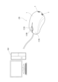
- FIG. 1 is a schematic perspective view showing an example of the appearance of an operating device CTR disclosed in the present application.
- Fig. 1 shows an example in which the operating device CTR disclosed in the present application is applied to a mouse used to operate an electronic device ELD such as a personal computer as a first embodiment.
- the operating device CTR has a housing 1 incorporating various components described later.
- An operating unit 2 that accepts an operation by an operator is disposed in the housing 1 of the operating device CTR.
- the operating device CTR (mouse) illustrated in Fig. 1 has a plurality of operating units 2, such as a pressing operation unit 2A such as a mouse button that accepts a pressing operation, and a rotating operation unit 2B such as a mouse wheel that accepts a vertical rotation operation.
- the control device CTR performs wired or wireless communication with the external electronic device ELD.
- the control device CTR shown in FIG. 1 performs wired communication via a communication line, and the communication line mediates the transmission and reception of electrical signals between the control device CTR and the electronic device ELD.
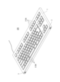
- FIG. 2 is a schematic perspective view showing an example of the appearance of the operating device CTR disclosed in the present application.
- Fig. 2 shows an example in which the operating device CTR disclosed in the present application is applied to a keyboard used to operate an electronic device ELD such as a personal computer, as a second embodiment.
- the operating device CTR includes a housing 1, and a plurality of key switches such as letter keys, numeric keys, and function keys are arranged on the housing 1 as a pressing operation section 2A.
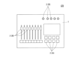
- FIG. 4 is a schematic perspective view showing an example of the appearance of the operating device CTR disclosed in the present application.
- Fig. 4 shows an example in which the operating device CTR disclosed in the present application is applied to an audio mixer as a fourth embodiment.
- the operating device CTR includes a housing 1, and the housing 1 includes a pressing operation unit 2A such as a push button that receives a pressing operation, a rotation operation unit 2B such as a dial that receives a rotation operation of horizontal rotation, and a sliding operation unit 2D such as a slider that receives a sliding operation.
- a pressing operation unit 2A such as a push button that receives a pressing operation
- a rotation operation unit 2B such as a dial that receives a rotation operation of horizontal rotation
- a sliding operation unit 2D such as a slider that receives a sliding operation.
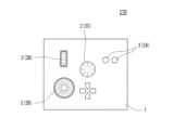
- FIG. 5 is a schematic plan view showing an example of the appearance of the operating device CTR disclosed in the present application.
- Fig. 5 shows an example in which the operating device CTR disclosed in the present application is applied to a composite controller as a fifth embodiment.
- the operating device CTR includes a housing 1, and the housing 1 includes various operating units 2, such as a pressing operation unit 2A that receives a pressing operation, a rotation operation unit 2B that receives a rotation operation of horizontal rotation, a rotation operation unit 2B that receives a rotation operation of vertical rotation, and a tilt operation unit 2C that receives a tilt operation.
- the control device CTR has a sound output unit 3 built into the housing 1, and the sound output unit 3 outputs sounds associated with the operations in synchronization with the operations.
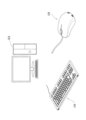
- FIG. 6 is a schematic plan view showing an example of an operation system using the operation device CTR disclosed in the present application.
- Fig. 6 is a schematic perspective view showing an example of an operation system using a plurality of operation devices CTR as a sixth embodiment.
- the operation device CTR disclosed in the present application can also be configured as an operation system using a plurality of devices for operating an electronic device ELD such as a personal computer.
- the operation system illustrated in FIG. 6 uses a keyboard and a mouse as the operation devices CTR, but it is possible to form an operation system using multiple of the various operation devices CTR illustrated as the first to fifth embodiments.
- the multiple operation devices CTR used as the operation system can communicate directly or indirectly via the electronic device ELD.
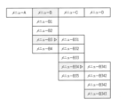
- menu B3 five types of sound systems are shown as the second submenu, and menu B34 is selected.
- menu B34 four types of sounds are shown as the third submenu, and menu B344 is selected.
- the operator displays the options as a menu tree and selects a preferred sound from the displayed options.
- the operating device CTR receives the detection signal on the control board 4, and under the control of the control unit 40, reads the selected original sound data 41a from the memory unit 41 based on the contents adjusted in the setting process (S202).
- the control unit 40 converts the read original sound data 41a into an analog electrical signal by the D/A conversion unit 43 (S203).
- the analog electrical signal D/A converted in step S203 is an electrical signal that indicates the waveform of the sound.
- the control unit 40 performs an adjustment process on the original sound data 41a converted into an analog electrical signal, in which the sound element adjustment unit 44 adjusts elements such as pitch and tempo based on the settings (S204).
- the sound element adjustment unit 44 may adjust the elements by performing amplitude adjustment processing for each frequency band, i.e., equalizer processing, in addition to adjusting the pitch and tempo.
- the control unit 40 amplifies the adjusted analog electrical signal using the amplifier 45 (S205), adjusts the volume using the volume adjustment unit 46 (S206), and outputs the signal as sound from the sound output unit 3 (S207).
- the sound output in step S207 is performed in synchronization with the operation received from the operation unit 2, so the operator recognizes the output sound as an operation sound, such as a clicking sound, that accompanies the operation.
- the operation device CTR disclosed in the present application adjusts the sound to be output based on the settings adjusted using the operation unit 2. Therefore, the operation device CTR disclosed in the present application makes it possible to set and output a preferred operation sound.
- the inventors of the present application have found through experiments, etc. that the sense of operation by the operator is affected by the operation sound, and by adjusting the operation sound, it is possible to adjust the feel of the operation. In addition, it is possible to recognize what operation was performed from the operation sound.
- the second embodiment is an embodiment in which the setting of sound adjustment and the output of sound are performed synchronously in the first embodiment.
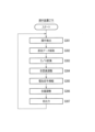
- Fig. 11 is a flowchart showing an example of the processing of the operation device CTR disclosed in the present application.
- the operation device CTR accepts a user's operation at the operation unit 2 and starts the setting and output processing.
- the operation device CTR detects the operation by the detection unit 20 (S301) and outputs a detection signal indicating the detected operation content to the control board 4.
- the operation device CTR receives the detection signal on the control board 4, and under the control of the control unit 40, reads original sound data 41a based on the operation content from the memory unit 41 based on the detected operation content (S302).
- the control unit 40 converts the read original sound data 41a into an analog electrical signal by the D/A conversion unit 43 (S303).
- the control unit 40 performs an adjustment process on the original sound data 41a converted into an analog electrical signal, adjusting elements such as pitch and tempo based on the detected operation content using the sound element adjustment unit 44 (S304).
- the control unit 40 amplifies the adjusted analog electrical signal using the amplifier unit 45 (S305), adjusts the volume using the volume adjustment unit 46 (S306), and outputs the signal as sound from the sound output unit 3 (S307).
- the operating device CTR reads the original sound data 41a in step S302 and performs an adjustment process in step S304 according to the detection content. For example, when a rotating operation unit 2B such as a dial is used as the operating unit 2 and a rotating operation is performed as the operation, the original sound data 41a is read and adjusted according to the detection content. Specifically, the control unit 40 of the operating device CTR detects a rotating operation on the rotating operation unit 2B in step S301. Then, the control unit 40 reads the original sound data 41a selected based on the rotating speed or rotating angle of the rotating operation in step S302, and adjusts the sound to be output based on the rotating speed or rotating angle of the rotating operation in step S304.
- a rotating operation unit 2B such as a dial
- the original sound data 41a is read and adjusted according to the detection content.
- the control unit 40 of the operating device CTR detects a rotating operation on the rotating operation unit 2B in step S301. Then, the control unit 40 reads the original sound data 41a selected
- the operating device CTR when the operating device CTR receives an operation from the rotating operation unit 2B such as a dial, it can change the sound to be output based on the rotating angle, for example, changing the pitch of the sound to be output in the first and second rotations. Furthermore, when the operation device CTR receives an operation from the rotation operation unit 2B, it can change the sound to be output based on the rotation speed, and can appropriately set, for example, to output a higher-pitched sound as the rotation speed becomes faster.
- the operation device CTR disclosed in the present application can adjust the sound to be output according to the rotation angle, such as the first rotation or second rotation, it may adjust the sound by selecting original sound data 41a based on the operation content for each rotation, or it may adjust the sound by performing an adjustment process on one original sound data 41a based on the operation content. The same applies to adjustments to the rotation speed.
- the operation device CTR which is an audio mixer, can adjust the sound output during the sliding operation of the sliding operation unit 2D such as a slider.
- the operation device CTR can be configured to perform processes such as generating a sound according to the distance each time a certain distance is moved, adjusting the pitch continuously during the sliding operation, and adjusting the pitch with a certain resolution during the sliding operation, and outputting the adjusted sound.
- the operating device CTR which is a keyboard
- the operating device CTR can be configured in various ways, such as changing the sound for operating a specific pressing operation unit 2A, for example, when the "Ctrl" key and the "F1" key are pressed simultaneously, in response to the operation of other keys.
- the third embodiment is a form in which the operation feel can be adjusted in addition to the sound output in the first or second embodiment.
- Fig. 12 is a block diagram showing an example of a functional configuration of the operation device CTR disclosed in the present application.
- the operation device CTR includes an operation unit 2 such as a pressing operation unit 2A, a rotating operation unit 2B, a tilting operation unit 2C, and a sliding operation unit 2D, and further includes a sound output unit 3, a control board 4, and other components.
- the operation unit 2 includes a detection unit 20 such as a linear sensor, a load unit 21 such as an MR (Magneto Rheological) fluid brake, and other components.
- MR Magnetic Rheological
- the storage unit 41 stores various information such as the original sound data 41a, as well as load data 41b.
- the load data 41b is digital data capable of reproducing the load caused by the operation of the operation unit 2.
- the control connection unit 47 is an interface circuit such as a motor driver that outputs commands to control the load unit 21 of the operation unit 2 based on the load data 41b.
- the MR fluid brake used as the load unit 21 will be further described.
- the MR fluid brake is a mechanism that uses a magnetorheological material to generate a load in response to operation of the operating unit 2.
- Materials such as magnetorheological fluid and magnetorheological powder are used as the magnetorheological material.
- MR fluid 210 a magnetorheological fluid (hereinafter, illustrated and described as MR fluid 210) is used as the magnetorheological material.
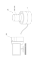
- the operating device CTR disclosed in this application generates a load by the load unit 21 on the rotation axis 2B0, which is the axis of rotation, for the operating unit 2, which is the rotating operating unit 2B, thereby generating an operating feel, a so-called clicking feeling, in response to the rotating operation.
- the container 211 has a substantially cylindrical container 211a with a bottom that is open on the upper bottom side, and a substantially disk-shaped lid portion 211b that covers the open opening of the container 211a.
- a part of the rotating shaft 2B0 is rotatably housed in the housing 211, and one end side of the rotating shaft 2B0 protrudes from the center of the cover part 211b of the housing 211 and is attached to the rotation operation part 2B.
- a first bearing part 212 such as a roller bearing is arranged near the center of the cover part 211b through which the rotating shaft 2B0 is inserted, and supports the rotating shaft 2B0 rotatably.
- the other end side of the rotating shaft 2B0 is rotatably supported by a second bearing part 213 such as a slide bearing attached to the inner surface of the lower bottom side of the housing 211, and is housed in the housing 211.
- a substantially disc-shaped disk part 214 is formed on the rotating shaft 2B0 so as to protrude in the radial direction, and the disk part 214 is housed in the housing 211.
- a cylindrical rotor 215 that rotates together with the disk portion 214 is attached to the underside of the disk portion 214 by a method such as screwing or gluing, or is molded integrally with the disk portion 214.
- the one operating device CTR and the other operating devices CTR transmit and receive information by wireless or wired communication via the communication connection unit 48.
- the one operating device CTR and the other operating devices CTR may communicate via an electronic device ELD.
- the one operating device CTR and the other operating devices CTR communicate via the communication unit 42 instead of or in addition to the communication connection unit 48.
- the operation system disclosed in the present application can, for example, set the click sound of the mouse, which is one operation device CTR, with the keyboard, which is the other operation device CTR.
- the setting and adjustment of the sound by the operation unit 2 of one operation device CTR may be performed before the operation by the operation unit 2 of the other operation device CTR, or may be performed in synchronization with the operation.
- the operating device CTR etc. disclosed in the present application provides excellent effects such as the ability to adjust (set) the sounds generated based on operation.
- the operating device CTR disclosed in the present application provides excellent effects such as the ability to create an operating feel that meets the preferences or requirements of the user.
- the operating device CTR etc. disclosed in this application is capable of adjusting the load on the operation, which provides an excellent effect of enabling the operation feel to be tailored to the user's preferences or needs.
Landscapes
- Engineering & Computer Science (AREA)
- Theoretical Computer Science (AREA)
- General Engineering & Computer Science (AREA)
- Human Computer Interaction (AREA)
- Physics & Mathematics (AREA)
- General Physics & Mathematics (AREA)
- Health & Medical Sciences (AREA)
- Audiology, Speech & Language Pathology (AREA)
- General Health & Medical Sciences (AREA)
- Position Input By Displaying (AREA)
- Input From Keyboards Or The Like (AREA)
- Mechanical Control Devices (AREA)
Abstract
使用者の嗜好又は要求に応じた音を出力することが可能な操作装置及び操作システムを提供する。 操作装置CTRは、操作者からの入力操作を受ける一又は複数の操作部2を備える。更に、操作装置CTRは、音を出力する音出力部3を備え、音出力部3は、操作部2が受け付けた操作に基づいて、音を出力するようにしてあり、操作部2から受け付けた操作に基づいて、音出力部3から出力する音を調整可能である。また、操作装置CTRは、操作部2が受け付けた操作に同期させて、音を調整するように構成することも可能である。更に、操作装置CTRは、音の出力に同期させて、操作部2に負荷を生じさせるように構成することも可能である。
Description
本発明は、操作者からの入力操作を受け付ける操作装置、及びそのような操作装置を用いた操作システムに関する。
コンピュータ等の電子機器と通信可能に接続され、使用者からの入力操作を受け付けるマウス、キーボード等の操作装置が普及している。このような操作装置では、操作者からの押圧操作を受け付けて回路を開閉するマイクロスイッチ等のスイッチが用いられている(例えば、特許文献1参照。)。マウス、キーボード等の操作装置は、様々な用途、状況に応じた様々な特性が要求されている。操作装置に要求される特性の1つとして、例えば、快適なクリック音及びクリック感があり、特許文献1では、クリック感の向上及び静音性の向上を狙ったマウス装置が開示されている。
従来のマウス等の操作装置において、クリック音等の操作に基づく音は、例えば、内蔵されているマイクロスイッチに依存しているため、音を変更することは困難であった。
しかしながら、使用者の嗜好及び要求は、多様化しており、使用者の嗜好に応じて、又は使用者の要求に応じて、操作に基づく音の変更が求められる場合がある。
本発明は斯かる事情に鑑みてなされたものであり、本願では、操作に基づく音の調整が可能な操作装置の開示を主たる目的とする。
また、本願では、そのような操作装置を用いた操作システムの開示を更に他の目的とする。
上記課題を解決するため、本願開示の操作装置は、操作者からの入力操作を受ける操作部と、前記操作部が受け付けた操作に基づいて、音を出力する音出力部と、前記操作部から受け付けた操作に基づいて、前記音出力部から出力する音を調整する制御部とを備えることを特徴とする。
更に、本願開示の操作装置は、操作者からの入力操作を受ける操作部と、音を出力する音出力部と、前記音出力部から出力する音を制御する制御部とを備え、前記制御部は、前記操作部が受け付けた操作に基づいて、前記音出力部から出力する音を調整する調整手段と、前記操作部が受け付けた操作に同期させて、前記調整手段が調整する音を、前記音出力部から出力させる出力制御手段とを有することを特徴とする。
また、本願開示の操作装置において、音の出力に用いられる原音データを記憶する記憶部を更に備え、前記制御部の前記調整手段は、原音データに基づくピッチ調整又はテンポ調整を含む調整を実行することを特徴とする。
また、本願開示の操作装置において、前記操作部に対する操作に負荷を生じさせる負荷部を更に備え、前記制御部は、前記音出力部からの音の出力に同期させて、前記負荷部により、前記操作部に負荷を生じさせることを特徴とする。
また、本願開示の操作装置において、前記負荷部は、磁気粘性体にて負荷を生じさせる流体ブレーキであることを特徴とする。
また、本願開示の操作装置において、前記操作部は、回動操作を受け付ける回動操作部を有し、前記調整手段は、前記回動操作部が受け付けた回動操作による回動速度に基づいて、前記音出力部から出力する音を調整するようにしてあり、前記出力制御手段は、音の調整に用いた前記回動操作部が受け付けた回動操作に同期させて、前記調整手段が調整する音を、前記音出力部から出力させることを特徴とする。
また、本願開示の操作装置において、押圧操作、回動操作、傾倒操作又は摺動操作を受け付ける前記操作部を備えることを特徴とする。
更に、本願開示の操作システムは、操作者からの入力操作を受け付ける第1の操作部及び第2の操作部と、音を出力する音出力部と、前記音出力部から出力する音を制御する制御部とを備え、前記制御部は、前記第1の操作部から受け付けた操作に基づいて、前記音出力部から出力する音を調整する調整手段と、前記第2の操作部から受け付けた操作に同期させて、前記調整手段が調整する音を、前記音出力部から出力させる出力制御手段とを有することを特徴とする。
本願開示の操作装置等は、音を出力する音出力部を備え、操作に基づき出力する音を調整可能である。これにより、本願開示の操作装置等は、使用者の嗜好又は要求に応えることが可能である等、優れた効果を奏する。
<適用例>
以下、本願開示の操作装置の実施形態の例について図面を参照しながら説明する。本願開示の操作装置は、例えば、パーソナルコンピュータ(以下、パソコンという)、ゲーム装置、産業機器、音響・映像装置等の電子機器の操作に用いられるマウス、キーボード、スティックコントローラ、音響ミキサー等の装置として実現される。操作装置は、操作者の入力操作を受け付ける一又は複数の操作部を備えている。操作部は、押圧操作を受け付ける押圧操作部、回動操作を受け付ける回動操作部、傾倒操作を受け付ける傾倒操作部、摺動操作を受け付ける摺動操作部等の様々な操作部に分類できる。以下では、図面を参照しながら、操作装置CTRとして図示された様々な装置について説明する。
以下、本願開示の操作装置の実施形態の例について図面を参照しながら説明する。本願開示の操作装置は、例えば、パーソナルコンピュータ(以下、パソコンという)、ゲーム装置、産業機器、音響・映像装置等の電子機器の操作に用いられるマウス、キーボード、スティックコントローラ、音響ミキサー等の装置として実現される。操作装置は、操作者の入力操作を受け付ける一又は複数の操作部を備えている。操作部は、押圧操作を受け付ける押圧操作部、回動操作を受け付ける回動操作部、傾倒操作を受け付ける傾倒操作部、摺動操作を受け付ける摺動操作部等の様々な操作部に分類できる。以下では、図面を参照しながら、操作装置CTRとして図示された様々な装置について説明する。
<実装形態>
先ず、本願開示の操作装置CTRを具現化した実装形態として、複数の実施形態の外観を例示して説明する。
先ず、本願開示の操作装置CTRを具現化した実装形態として、複数の実施形態の外観を例示して説明する。
<第1実施形態>
図1は、本願開示の操作装置CTRの外観の一例を示す概略斜視図である。図1は、第1実施形態として、本願開示の操作装置CTRをパソコン等の電子機器ELDの操作に用いるマウスに適用した例を示している。操作装置CTRは、後述する各種構成を内蔵した筐体1を備えている。操作装置CTRの筐体1には、操作者の操作を受け付ける操作部2が配置されている。図1に例示する操作装置CTR(マウス)は、押圧操作を受け付けるマウスボタン等の押圧操作部2A、縦回転の回動操作を受け付けるマウスホイール等の回動操作部2B等の複数の操作部2を備えている。
図1は、本願開示の操作装置CTRの外観の一例を示す概略斜視図である。図1は、第1実施形態として、本願開示の操作装置CTRをパソコン等の電子機器ELDの操作に用いるマウスに適用した例を示している。操作装置CTRは、後述する各種構成を内蔵した筐体1を備えている。操作装置CTRの筐体1には、操作者の操作を受け付ける操作部2が配置されている。図1に例示する操作装置CTR(マウス)は、押圧操作を受け付けるマウスボタン等の押圧操作部2A、縦回転の回動操作を受け付けるマウスホイール等の回動操作部2B等の複数の操作部2を備えている。
操作装置CTRは、音を出力するスピーカ等の音出力部3を筐体1内に備えている。なお、図1では、便宜上、筐体1に開設されたスリット状の開口を音出力部3として図示しているが、実際の音出力部3は、筐体1の内側で、開口に対応する位置に配置されている。音出力部3は、例えば、押圧操作部2Aに対する押圧操作に同期して、押圧操作に伴う音、所謂、クリック音を模した音を出力する。
操作装置CTRは、外部の電子機器ELDと有線通信又は無線通信を行う。図1に例示する操作装置CTRは、通信線にて有線通信を行う形態であり、通信線にて、操作装置CTR及び電子機器ELD間で電気信号の送受信を媒介する。
押圧操作部2A及び回動操作部2Bは、操作装置CTRが備える操作部2に対する形状及び構造に基づく称呼である。操作装置CTRが備える操作部2は、機能上、操作を受けて、音出力部3から操作に同期して音を出力させる機能と、操作を受けて、音出力部3から出力する音を調整する機能とを備えている。操作装置CTRが、図1に例示するマウスである場合、例えば、マウスホイールが調整用の回動操作部2Bとして機能し、マウスボタンが同期した音の出力用の押圧操作部2Aとして機能する。また、操作装置CTRは、音の調整用及び出力用の機能を、一のマウスボタンに持たせるように構成することも可能である。
<第2実施形態>
図2は、本願開示の操作装置CTRの外観の一例を示す概略斜視図である。図2は、第2実施形態として、本願開示の操作装置CTRをパソコン等の電子機器ELDの操作に用いるキーボードに適用した例を示している。操作装置CTRは、筐体1を備え、筐体1には、文字キー、数字キー、ファンクションキー等の複数のキースイッチが押圧操作部2Aとして配列されている。
図2は、本願開示の操作装置CTRの外観の一例を示す概略斜視図である。図2は、第2実施形態として、本願開示の操作装置CTRをパソコン等の電子機器ELDの操作に用いるキーボードに適用した例を示している。操作装置CTRは、筐体1を備え、筐体1には、文字キー、数字キー、ファンクションキー等の複数のキースイッチが押圧操作部2Aとして配列されている。
操作装置CTRは、筐体1内に、音出力部3を内蔵し、筐体1には、音出力部3に対応する位置に、スリット状の開口が形成されている。音出力部3は、例えば、押圧操作部2Aに対する押圧操作に同期して、押圧操作に伴う音に模した音を出力する。
<第3実施形態>
図3は、本願開示の操作装置CTRの外観の一例を示す概略斜視図である。図3は、第3実施形態として、本願開示の操作装置CTRをスティックコントローラに適用した例を示している。操作装置CTRは、筐体1を備え、筐体1は、傾倒させて操作するスティック等の傾倒操作部2Cを備えている。なお、スティックは、押圧操作を受け付ける押圧操作部2A、横回転の回動操作を受け付ける回動操作部2Bとしても機能する。
図3は、本願開示の操作装置CTRの外観の一例を示す概略斜視図である。図3は、第3実施形態として、本願開示の操作装置CTRをスティックコントローラに適用した例を示している。操作装置CTRは、筐体1を備え、筐体1は、傾倒させて操作するスティック等の傾倒操作部2Cを備えている。なお、スティックは、押圧操作を受け付ける押圧操作部2A、横回転の回動操作を受け付ける回動操作部2Bとしても機能する。
<第4実施形態>
図4は、本願開示の操作装置CTRの外観の一例を示す概略斜視図である。図4は、第4実施形態として、本願開示の操作装置CTRを、音響ミキサーに適用した例を示している。操作装置CTRは、筐体1を備え、筐体1は、押圧操作を受け付ける押しボタン等の押圧操作部2A、横回転の回動操作を受け付けるダイアル等の回動操作部2B、及び摺動操作を受け付けるスライダ等の摺動操作部2Dを備えている。
図4は、本願開示の操作装置CTRの外観の一例を示す概略斜視図である。図4は、第4実施形態として、本願開示の操作装置CTRを、音響ミキサーに適用した例を示している。操作装置CTRは、筐体1を備え、筐体1は、押圧操作を受け付ける押しボタン等の押圧操作部2A、横回転の回動操作を受け付けるダイアル等の回動操作部2B、及び摺動操作を受け付けるスライダ等の摺動操作部2Dを備えている。
操作装置CTRは、筐体1内に、音出力部3(図示せず)を内蔵し、音出力部3は、押圧操作、回動操作、摺動操作等の操作に同期して、操作に伴う音を出力する。
<第5実施形態>
図5は、本願開示の操作装置CTRの外観の一例を示す概略平面図である。図5は、第5実施形態として、本願開示の操作装置CTRを、複合コントローラに適用した例を示している。操作装置CTRは、筐体1を備え、筐体1は、押圧操作を受け付ける押圧操作部2A、横回転の回動操作を受け付ける回動操作部2B、縦回転の回動操作を受け付ける回動操作部2B、傾倒操作を受け付ける傾倒操作部2C等の様々な操作部2を備えている。
図5は、本願開示の操作装置CTRの外観の一例を示す概略平面図である。図5は、第5実施形態として、本願開示の操作装置CTRを、複合コントローラに適用した例を示している。操作装置CTRは、筐体1を備え、筐体1は、押圧操作を受け付ける押圧操作部2A、横回転の回動操作を受け付ける回動操作部2B、縦回転の回動操作を受け付ける回動操作部2B、傾倒操作を受け付ける傾倒操作部2C等の様々な操作部2を備えている。
操作装置CTRは、筐体1内に音出力部3を内蔵し、音出力部3は、操作に同期して、操作に伴う音を出力する。
<第6実施形態>
図6は、本願開示の操作装置CTRを用いた操作システムの一例を示す概略平面図である。図6は、第6実施形態として、複数の操作装置CTRを用いた操作システムの一例を示す概略斜視図である。本願開示の操作装置CTRは、パソコン等の電子機器ELDの操作用に、複数の装置を用いた操作システムとして構成することも可能である。
図6は、本願開示の操作装置CTRを用いた操作システムの一例を示す概略平面図である。図6は、第6実施形態として、複数の操作装置CTRを用いた操作システムの一例を示す概略斜視図である。本願開示の操作装置CTRは、パソコン等の電子機器ELDの操作用に、複数の装置を用いた操作システムとして構成することも可能である。
図6に例示する操作システムは、キーボード及びマウスをそれぞれ操作装置CTRとして用いた形態を例示しているが、第1乃至第5実施形態として例示した様々な操作装置CTRを複数用いて操作システムを形成することが可能である。操作システムとして用いられる複数の操作装置CTRは、直接又は電子機器ELDを介して間接的に通信することが可能である。
<機能構成及び処理>
次に、本願開示の操作装置CTRの機能構成及び処理の例として、複数の実施形態を例示して説明する。
次に、本願開示の操作装置CTRの機能構成及び処理の例として、複数の実施形態を例示して説明する。
<第1実施形態>
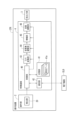
図7は、本願開示の操作装置CTRの機能構成の一例を概略的に示すブロック図である。操作装置CTRは、前述の押圧操作部2A、回動操作部2B、傾倒操作部2C、摺動操作部2D等の操作部2、及び音出力部3を備え、筐体1内に制御基板4を備えている。操作部2は、操作内容を検出し、検出内容を示す検出信号を制御基板4へ出力するマウスエンコーダ等の検出部20を備えている。制御基板4は、制御部40、記憶部41、通信部42、D/A変換部43、音要素調整部44、増幅部45、音量調整部46等の各種回路を搭載している。制御基板4に搭載された各種回路には、図示しない電源から電力が供給されている。
図7は、本願開示の操作装置CTRの機能構成の一例を概略的に示すブロック図である。操作装置CTRは、前述の押圧操作部2A、回動操作部2B、傾倒操作部2C、摺動操作部2D等の操作部2、及び音出力部3を備え、筐体1内に制御基板4を備えている。操作部2は、操作内容を検出し、検出内容を示す検出信号を制御基板4へ出力するマウスエンコーダ等の検出部20を備えている。制御基板4は、制御部40、記憶部41、通信部42、D/A変換部43、音要素調整部44、増幅部45、音量調整部46等の各種回路を搭載している。制御基板4に搭載された各種回路には、図示しない電源から電力が供給されている。
制御部40は、装置全体を制御する回路であり、例えば、VLSI、LSI等の集積回路を搭載したマイクロコンピュータ等の制御回路を用いて構成されている。
記憶部41は、制御部40にて処理される各種情報を記憶する半導体メモリ等のメモリである。記憶部41は、クリック音等の操作音として出力する音の元となる複数の原音データ41a等の各種情報を記憶している。原音データ41aは、操作音の波形を再現可能なデジタルデータである。原音データ41aは、例えば、様々な音のサンプリング結果に基づいて生成されている。記憶部41は、例えば、金属系の音、鈍い音、柔らかな音等、様々な音の波形を再現可能な原音データ41aを複数記憶している。記憶されている複数の原音データ41aは、例えば、金属系の音、鈍い音等の系統毎に紐付けられ、また、操作者の好みに応じたライブラリとしてグルーピングされている。
通信部42は、パソコン等の他の電子機器ELDと有線通信又は無線通信にて通信する回路である。有線通信の場合、通信部42は、通信線及び通信のための各種回路を備えている。無線通信の場合、通信部42は、アンテナ及び通信のための各種回路を備えている。
D/A変換部43は、原音データ41a等のデジタルデータをアナログの電気信号に変換する回路である。
音要素調整部44は、D/A変換部43にてアナログデータに変換された電気信号のピッチ、テンポ、周波数等の音の要素を調整する回路である。
増幅部45は、アナログデータの電気信号を増幅し、音出力部3へ出力するアンプである。
音量調整部46は、音出力部3から出力する音の音量を調整する回路である。
次に、第1実施形態における処理について説明する。本願開示の操作装置CTRは、操作装置CTRが受け付けた操作に基づいて、音出力部3から音を出力する。また、出力する音は、操作部2から受け付けた操作に基づいて調整可能である。
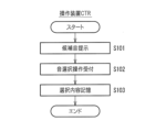
操作装置CTRによる音の設定処理について説明する。図8は、本願開示の操作装置CTRの処理の一例を示すフローチャートである。操作者は、操作装置CTRを操作し、音の設定モードに移行させる。設定モードに移行した操作装置CTRの制御部40は、操作者による操作部2に対する操作に応じて、候補となる音を提示する(S101)。操作者は、提示された音から所望する音を選択する操作を行う。操作装置CTRの制御部40は、操作部2から音を選択する操作を受け付け(S102)、選択内容を記憶部41に記憶する(S103)。操作装置CTRは、設定処理により、操作部2にて、操作を受け付けた場合に出力する音を調整することが可能である。
音の提示は、候補となる音を音出力部3から出力することにより実行される。なお、操作装置CTRは、設定処理として、音の提示及び選択の受け付けを一の操作で行えるよう構成することも可能である。例えば、「Ctrl」キーと「F1」キーとを同時に押圧した場合に、音の設定と共に、設定後の音を出力するショートカットキーとしての機能を持たせる等、本願開示の操作装置CTRは様々な形態に展開することが可能である。
更に、音の提示は、接続している電子機器ELDが備える液晶モニタ等の表示部に、候補となる音の選択肢を、メニューツリー等の形式で表示するようにしてもよい。図9は、本願開示の操作装置CTRに接続された電子機器ELDが備える表示部に表示される画像の一例を示す説明図である。図9は、候補となる音の選択肢を、メニューツリー形式で示している。候補となる音に係る原音データ41aは、系統毎に紐付けられており、系統付けられた状態に基づいてメニューツリーが決定されている。図8では、トップメニューとして、メニューA~Dの4種類の音の系統が示されており、メニューBが選択されている。メニューBには、第1サブメニューとして4種類の音の系統が示されており、メニューB3が選択されている。メニューB3には、第2サブメニューとして5種類の音の系統が示されており、メニューB34が選択されている。メニューB34には、第3サブメニューとして4種類の音が示されており、メニューB344が選択されている。操作者は、メニューツリーとして選択肢を表示させ、表示された選択肢から好みの音を辿って選択する操作を行う。
次に、操作装置CTRによる音の出力処理について説明する。図10は、本願開示の操作装置CTRの処理の一例を示すフローチャートである。操作装置CTRは、使用者の操作を操作部2にて受け付けて音出力処理を開始する。操作装置CTRは、検出部20により、操作を検出し(S201)、検出した操作内容を示す検出信号を制御基板4へ出力する。
操作装置CTRは、制御基板4にて検出信号を受信し、制御部40の制御により、設定処理にて調整された内容に基づいて、記憶部41から選択されている原音データ41aを読み取る(S202)。
制御部40は、読み取った原音データ41aを、D/A変換部43により、アナログの電気信号に変換する(S203)。ステップS203にてD/A変換したアナログの電気信号は、音の波形を示す電気信号となっている。
制御部40は、アナログの電気信号に変換した原音データ41aに対し、音要素調整部44により、設定されている内容に基づいてピッチ、テンポ等の要素を調整する調整処理を行う(S204)。ステップS204において、音要素調整部44は、要素の調整として、ピッチ及びテンポの調整以外に、周波数帯毎の振幅調整処理、即ち、イコライザ処理を行うようにしてもよい。
制御部40は、調整後のアナログの電気信号を、増幅部45により増幅し(S205)、音量調整部46により、音量を調整して(S206)、音出力部3から音として出力する(S207)。ステップS207の音の出力は、操作部2から受け付けた操作に同期して行われるため、操作者は、出力された、音を操作に伴うクリック音等の操作音として認識する。
以上の処理により、本願開示の操作装置CTRは、操作部2を用いて調整した設定に基づいて、出力する音を調整しながら出力する。従って、本願開示の操作装置CTRは、好みの操作音を設定し、出力することが可能である。本願発明者らは、操作者による操作感覚は、操作音に影響されるとの知見を実験等から得ており、操作音を調整することにより、操作感触を調整することが可能である。また、操作音は、操作音からどのような操作を行ったかを認識することが可能である。
<第2実施形態>
第2実施形態は、第1実施形態において、音の調整の設定及び音の出力を同期して行う形態である。図11は、本願開示の操作装置CTRの処理の一例を示すフローチャートである。操作装置CTRは、使用者の操作を操作部2にて受け付けて設定及び出力処理を開始する。操作装置CTRは、検出部20により、操作を検出し(S301)、検出した操作内容を示す検出信号を制御基板4へ出力する。
第2実施形態は、第1実施形態において、音の調整の設定及び音の出力を同期して行う形態である。図11は、本願開示の操作装置CTRの処理の一例を示すフローチャートである。操作装置CTRは、使用者の操作を操作部2にて受け付けて設定及び出力処理を開始する。操作装置CTRは、検出部20により、操作を検出し(S301)、検出した操作内容を示す検出信号を制御基板4へ出力する。
操作装置CTRは、制御基板4にて検出信号を受信し、制御部40の制御により、検出した操作内容に基づいて、記憶部41から操作内容に基づく原音データ41aを読み取る(S302)。
制御部40は、読み取った原音データ41aを、D/A変換部43により、アナログの電気信号に変換する(S303)。
制御部40は、アナログの電気信号に変換した原音データ41aに対し、音要素調整部44により、検出した操作内容に基づいてピッチ、テンポ等の要素を調整する調整処理を行う(S304)。
制御部40は、調整後のアナログの電気信号を、増幅部45により増幅し(S305)、音量調整部46により、音量を調整して(S306)、音出力部3から音として出力する(S307)。
操作装置CTRは、ステップS302の原音データ41aの読み取り及びステップS304の調整処理を検出内容に応じて行う。例えば、操作部2としてダイアル等の回動操作部2Bを用い、操作として回動操作を行う場合に、検出内容に応じた原音データ41aの読み取り及び調整処理が行われる。具体的には、操作装置CTRの制御部40は、ステップS301にて回動操作部2Bに対する回動操作を検出する。そして、制御部40は、ステップS302にて、回動操作による回動速度又は回動角度に基づいて選択した原音データ41aを読み取り、ステップS304にて、回動操作による回動速度又は回動角度に基づいて、出力する音を調整する。即ち、操作装置CTRは、ダイアル等の回動操作部2Bから操作を受け付けた場合に、回動角度に基づいて出力する音を変更し、例えば、1周目、2周目で出力する音の高さを変えることができる。また、操作装置CTRは、回動操作部2Bから操作を受け付けた場合に、回動速度に基づいて出力する音を変更し、例えば、回動速度が速くなる程、高い音を出力する等、適宜設定することができる。なお、本願開示の操作装置CTRは、1周目、2周目等、回動角度に応じて出力する音を調整できるのであれば、操作内容に基づく原音データ41aを周回の都度選択することにより音を調整しても、操作内容に基づき一の原音データ41aに対して調整処理にて音を調整するようにしてもよい。回動速度に対する調整も同様である。
また、第2実施形態の応用例として、マウスである操作装置CTRは、マウスホイール等の回動操作部2Bの回動操作に対して、回動操作中に出力する音を調整することが可能である。例えば、操作装置CTRは、回動速度に応じて、音の出力頻度の調整、音の長さの調整、音程の調整等の処理を行い、調整後の音を出力するように構成することが可能である。
更に、第2実施形態の応用例として、音響ミキサーである操作装置CTRは、スライダ等の摺動操作部2Dの摺動操作に対して、摺動操作中に出力する音を調整することが可能である。例えば、操作装置CTRは、摺動操作に対して、一定の距離を動かす毎に距離に応じた音の発生、摺動操作中の無段階での音程の調整、摺動操作中の一定の分解能での音程の調整等の処理を行い、調整後の音を出力するように構成することが可能である。
更に、第2実施形態の応用例として、キーボードである操作装置CTRは、特定の押圧操作部2Aに対する操作、例えば「Ctrl」キーと「F1」キーとを同時に押圧した場合に、他のキーの操作に対する音が変化する等、様々な構成とすることが可能である。
<第3実施形態>
第3実施形態は、第1実施形態又は第2実施形態において、出力する音に加えて、操作感触を調整可能とする形態である。図12は、本願開示の操作装置CTRの機能構成の一例を概略的に示すブロック図である。操作装置CTRは、押圧操作部2A、回動操作部2B、傾倒操作部2C、摺動操作部2D等の操作部2を備え、更に音出力部3、制御基板4等の構成を備えている。操作部2は、リニアセンサ等の検出部20、MR(Magneto Rheological )流体ブレーキ等の負荷部21等の構成を備えている。制御基板4は、制御部40、記憶部41、通信部42、D/A変換部43、音要素調整部44、増幅部45、音量調整部46、制御接続部47等の各種回路を搭載している。
第3実施形態は、第1実施形態又は第2実施形態において、出力する音に加えて、操作感触を調整可能とする形態である。図12は、本願開示の操作装置CTRの機能構成の一例を概略的に示すブロック図である。操作装置CTRは、押圧操作部2A、回動操作部2B、傾倒操作部2C、摺動操作部2D等の操作部2を備え、更に音出力部3、制御基板4等の構成を備えている。操作部2は、リニアセンサ等の検出部20、MR(Magneto Rheological )流体ブレーキ等の負荷部21等の構成を備えている。制御基板4は、制御部40、記憶部41、通信部42、D/A変換部43、音要素調整部44、増幅部45、音量調整部46、制御接続部47等の各種回路を搭載している。
記憶部41は、原音データ41aの他、負荷データ41b等の各種情報を記憶している。負荷データ41bは、操作部2の操作に対して生じさせる負荷を再現可能なデジタルデータである。
制御接続部47は、負荷データ41bに基づいて、操作部2の負荷部21を制御する命令を出力するモータドライバ等のインターフェース回路である。
負荷部21として用いられるMR流体ブレーキについて更に説明する。MR流体ブレーキは、磁気粘性体を用い、操作部2に対する操作に対して負荷を生じさせる機構である。磁気粘性体としては、磁気粘性流体、磁気粘性粉体等の物質が用いられる。以下では、磁気粘性体として、磁気粘性流体(以下、MR流体210として図示及び説明を行う)を用いた形態を例示して説明する。本願開示の操作装置CTRは、回動操作部2Bである操作部2に対し、回動の軸となる回動軸2B0に対して負荷部21による負荷を生じさせることで、回動操作に対する操作感、所謂クリック感を生じさせる。
図13は、本願開示の操作装置CTRが備える負荷部21の内部構造の一例を模式的に示す概略断面図である。図14は、本願開示の操作装置CTRが備える負荷部21の内部構造の一例を示す概略断面分解斜視図である。負荷部21は、略有底円筒状をなす収容体211を備えており、収容体211の一方の底面の中心を通るように、回動軸2B0が挿通されている。以降の説明では、便宜上、図13及び図14の上側を上とし、下側を下として説明する。なお、上下の方向は、説明の便宜上の称呼であり、取付方向を限定するものではない。収容体211は、上底側が開放された略有底円筒状の容器211aと、容器211aの開放された開口を塞ぐ略円板状の蓋部211bとを備えている。回動軸2B0の一部は、収容体211内に回動可能に収容されており、回動軸2B0の一端側は収容体211の蓋部211bの中心から突出し、回動操作部2Bに取り付けられている。回動軸2B0が挿通された蓋部211bの中心近傍には、コロ軸受等の第1軸受部212が配置されており、回動軸2B0を回動自在に支持している。回動軸2B0の他端側は、収容体211の下底側の内面に取り付けられた滑り軸受等の第2軸受部213に回動可能に軸支され、収容体211内に収まっている。回動軸2B0には、略円板状のディスク部214が径方向へ張り出すように形成されており、ディスク部214は、収容体211内に収容されている。ディスク部214の下面には、ディスク部214と共に回動する円筒状のロータ215が、ネジ止め、接着等の方法で取り付けられ、又はディスク部214に一体成形されている。
収容体211の内部には、回動軸2B0のディスク部214、ロータ215等の部材にMR流体210が接触するように、MR流体210が封入された流体室216が形成されている。流体室216に封入されたMR流体210は、回動軸2B0のディスク部214及びロータ215と接触しているため、MR流体210の粘性は、回動軸2B0の回動を妨げる負荷となる。ロータ215の下方には、MR流体210の粘度を制御するための磁場を発生させるコイル等の磁場発生部217が、回動軸2B0の周囲を巻回するように配置されている。そして、収容体211の内部には、磁場発生部217にて発生した磁場でMR流体210の粘度を効率的に制御するため、ヨーク218が配置されている。なお、図13及び図14を用いて説明したMR流体ブレーキは、様々な形態に展開できる負荷部21の一例であり、これに限るものではない。本願開示の操作装置CTRは、回動操作部2B等の操作部2が受け付ける操作に対し、様々な方法で負荷を生じさせる負荷部21を備えることが可能である。
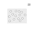
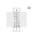
MR流体210について更に説明する。図15及び図16は、本願開示の操作装置CTRが備える負荷部21に用いられるMR流体210(磁気粘性流体)の特性を模式的に示す説明図である。図15は、磁場の影響を受けていない状態のMR流体210を概念的に示しており、図16は、磁場を発生させた状態のMR流体210を概念的に示している。MR流体210は、水、油等の液体に、直径1~10μmの強磁性体の微粒子を分散させた機能性流体である。図15に例示するように磁場の影響を受けていない状態では、微粒子は、液体中に均一に分散している。図16に例示するように磁場の影響を受けると強磁性体の微粒子が磁化して引きつけ合うことでクラスターを形成するため、液体の粘度が高くなる。クラスターの形成の程度は、磁場により制御することができるため、磁場を制御することで粘度を調整し、調整した粘度により回動軸2B0にかかる負荷を制御することが可能となる。
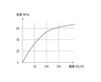
図17は、本願開示の操作装置CTRが備える負荷部21に用いられるMR流体210(磁気粘性流体)の特性を示すグラフである。図17は、横軸に磁場の強さをとり、MR流体210の粘度をとってその関係を示している。図17に例示するように、磁場と粘度とは、1対1で対応しているため、磁場を制御することにより、粘度の調整が可能である。
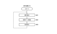
次に、第3実施形態における処理について説明する。負荷部21による操作負荷を設定する処理は、図8を用いて説明した第1実施形態における設定処理と実質的に同様である。次に操作装置CTRの負荷部21による負荷処理について説明する。図18は、本願開示の操作装置CTRの処理の一例を示すフローチャートである。操作装置CTRは、使用者の操作を操作部2にて受け付けて、負荷処理を開始する。操作装置CTRは、検出部20により、操作を検出し(S401)、検出した操作内容を示す操作信号を制御基板4へ出力する。
操作装置CTRは、制御基板4にて検出信号を受信し、制御部40の制御により、設定された内容に基づいて、記憶部41から負荷データ41bを読み取る(S402)。
制御部40は、読みとった負荷データ41bを制御接続部47へ送り、制御接続部47から操作部2へ負荷部21を振動させる命令を出力する。操作部2は、入力された命令に基づいて負荷部21による負荷を生じさせる(S403)。操作装置CTRは、負荷部21による負荷、例えば、回動操作部2Bに対する回動操作に対し、所定の回動角度、所定の回動速度等の設定に応じて生じさせる。
図18に例示した負荷処理により、回動操作部2Bの回動軸2B0に、回動に対する負荷がかかる。操作者は、回動操作に対する負荷を、「カチッ、カチッ」等の操作感として感得する。本願開示の操作装置CTRは、操作に伴う音出力処理及び負荷処理を同期して実行することができる。従って、操作者は、操作に伴う操作音及び操作感を、クリック音及びクリック感として感得することが可能となる。
なお、本願開示の操作装置CTRは、回動操作部2B以外の操作部2、例えば、押圧操作部2A、傾倒操作部2C、摺動操作部2Dに対して負荷部21を設けることも可能である。例えば、本願開示の操作装置CTRは、摺動操作部2Dに対して負荷部21を設けた場合、摺動操作の距離に応じてクリック感を発生させる等、様々な形態に展開することが可能である。また、例えば、本願開示の操作装置CTRは、本来、クリック感が生じないリニアスイッチを用いた押圧操作部2Aに対して、負荷部21を設けて、任意の位置でクリック感を発生させる等、様々な形態に展開することが可能である。
<第4実施形態>
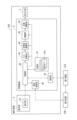
第4実施形態は、第1実施形態、第2実施形態又は第3実施形態において、複数の操作装置CTRを用いる形態である。例えば、実施形態の外観の例として図6を用いて説明した第6実施形態に適用される機能構成である。図19は、本願開示の操作装置CTRを用いた操作システムの機能構成例の一例を概略的に示すブロック図である。図19は、複数の操作装置CTR、例えば、キーボード及びマウスを備える操作システムを例示している。複数の操作装置CTRのそれぞれの構成は、第1実施形態等の形態に例示した操作装置CTRと実質的に同様であり、更に、他の操作装置CTRと通信する通信接続部48を備える。そして、一の操作装置CTR及び他の操作装置CTRは、通信接続部48を介した無線又有線通信により、情報の送受信を行う。なお、一の操作装置CTR及び他の操作装置CTRは、電子機器ELDを介して通信を行うようにしてもよい。その場合、一の操作装置CTR及び他の操作装置CTRは、通信接続部48に代替して又は併用して通信部42を介した通信を行う。
第4実施形態は、第1実施形態、第2実施形態又は第3実施形態において、複数の操作装置CTRを用いる形態である。例えば、実施形態の外観の例として図6を用いて説明した第6実施形態に適用される機能構成である。図19は、本願開示の操作装置CTRを用いた操作システムの機能構成例の一例を概略的に示すブロック図である。図19は、複数の操作装置CTR、例えば、キーボード及びマウスを備える操作システムを例示している。複数の操作装置CTRのそれぞれの構成は、第1実施形態等の形態に例示した操作装置CTRと実質的に同様であり、更に、他の操作装置CTRと通信する通信接続部48を備える。そして、一の操作装置CTR及び他の操作装置CTRは、通信接続部48を介した無線又有線通信により、情報の送受信を行う。なお、一の操作装置CTR及び他の操作装置CTRは、電子機器ELDを介して通信を行うようにしてもよい。その場合、一の操作装置CTR及び他の操作装置CTRは、通信接続部48に代替して又は併用して通信部42を介した通信を行う。
一方の操作装置CTRの操作部2及び他方の操作装置CTRの操作部2は、それぞれ機能を割り当てることが可能である。例えば、一方の操作装置CTRが備える制御部40は、他方の操作部2から受け付けた操作に基づいて、自装置の音出力部3から出力する音の調整を設定することが可能である。そして、一方の操作装置CTRが備える制御部40は、自装置の操作部2から受け付けた操作に同期させて、調整された音を、自装置の音出力部3から出力する。操作システムが備える操作装置CTRの音の調整及び出力に係る処理は、第1実施形態等の形態に例示した処理と実質的に同様である。従って、本願開示の操作システムは、例えば、一方の操作装置CTRであるマウスのクリック音を、他方の操作装置CTRであるキーボードで設定することが可能となる。一方の操作装置CTRの操作部2による音の設定及び調整は、他方の操作装置CTRの操作部2による操作の前に行っても、操作と同期して行ってもよい。
以上のように、本願開示の操作装置CTR等は、操作に基づき発生する音の調整(設定)をすることが可能である等、優れた効果を奏する。これにより、本願開示の操作装置CTRは、使用者の嗜好又は要求に応える操作感を演出することが可能である等、優れた効果を奏する。
更に、本願開示の操作装置CTR等は、出力する音を操作中に調整することができるので、例えば、操作音で、回動操作を何回転行ったか等の操作の状況を知得することが可能である等、優れた効果を奏する。
更に、本願開示の操作装置CTR等は、操作に対する負荷を調整することが可能であり、これにより、使用者の嗜好又は要求に応える操作感を演出することが可能である等、優れた効果を奏する。
更に、本願開示の操作装置CTR等は、一の操作部2で、調整及び音の出力を担うようにしてもよく、二の操作部2で調整及び音の出力を分担するようにしてもよく、更には、二の操作部2をそれぞれ異なる操作装置CTRが備える形態として実装してもよい。
本発明は、以上説明した実施形態に限定されるものではなく、他の様々な形態で実施することが可能である。そのため、上述した実施形態はあらゆる点で単なる例示に過ぎず、限定的に解釈してはならない。本発明の技術範囲は、請求の範囲によって説明するものであって、明細書本文には何ら拘束されない。更に、請求の範囲の均等範囲に属する変形及び変更は、全て本発明の範囲内のものである。
即ち、本願開示の操作装置CTRは、以下の付記に係る様々な形態に展開することが可能である。
CTR 操作装置
1 筐体
2 操作部
2A 押圧操作部
2B 回動操作部
2B0 回動軸
2C 傾倒操作部
2D 摺動操作部
20 検出部
21 負荷部
210 MR流体(磁気粘性体)
211 収容体
211a 容器
211b 蓋部
212 第1軸受け部
213 第2軸受け部
214 ディスク部
215 ロータ
216 流体室
217 磁場発生部
218 ヨーク
3 音出力部
4 制御基板
40 制御部
41 記憶部
41a 原音データ
41b 負荷データ
42 通信部
43 D/A変換部
44 音要素調整部(調整部)
45 増幅部
46 音量調整部
47 制御接続部
48 通信接続部
ELD 電子機器
1 筐体
2 操作部
2A 押圧操作部
2B 回動操作部
2B0 回動軸
2C 傾倒操作部
2D 摺動操作部
20 検出部
21 負荷部
210 MR流体(磁気粘性体)
211 収容体
211a 容器
211b 蓋部
212 第1軸受け部
213 第2軸受け部
214 ディスク部
215 ロータ
216 流体室
217 磁場発生部
218 ヨーク
3 音出力部
4 制御基板
40 制御部
41 記憶部
41a 原音データ
41b 負荷データ
42 通信部
43 D/A変換部
44 音要素調整部(調整部)
45 増幅部
46 音量調整部
47 制御接続部
48 通信接続部
ELD 電子機器
Claims (8)
- 操作者からの入力操作を受ける操作部と、
前記操作部が受け付けた操作に基づいて、音を出力する音出力部と、
前記操作部から受け付けた操作に基づいて、前記音出力部から出力する音を調整する制御部と
を備えることを特徴とする操作装置。 - 操作者からの入力操作を受ける操作部と、
音を出力する音出力部と、
前記音出力部から出力する音を制御する制御部と
を備え、
前記制御部は、
前記操作部が受け付けた操作に基づいて、前記音出力部から出力する音を調整する調整手段と、
前記操作部が受け付けた操作に同期させて、前記調整手段が調整する音を、前記音出力部から出力させる出力制御手段と
を有する
ことを特徴とする操作装置。 - 請求項2に記載の操作装置であって、
音の出力に用いられる原音データを記憶する記憶部を更に備え、
前記制御部の前記調整手段は、
原音データに基づくピッチ調整又はテンポ調整を含む調整を実行する
ことを特徴とする操作装置。 - 請求項2又は請求項3に記載の操作装置であって、
前記操作部に対する操作に負荷を生じさせる負荷部を更に備え、
前記制御部は、
前記音出力部からの音の出力に同期させて、前記負荷部により、前記操作部に負荷を生じさせる
ことを特徴とする操作装置。 - 請求項4に記載の操作装置であって、
前記負荷部は、磁気粘性体にて負荷を生じさせる流体ブレーキである
ことを特徴とする操作装置。 - 請求項2乃至請求項5のいずれかに記載の操作装置であって、
前記操作部は、回動操作を受け付ける回動操作部を有し、
前記調整手段は、前記回動操作部が受け付けた回動操作による回動速度に基づいて、前記音出力部から出力する音を調整するようにしてあり、
前記出力制御手段は、音の調整に用いた前記回動操作部が受け付けた回動操作に同期させて、前記調整手段が調整する音を、前記音出力部から出力させる
ことを特徴とする操作装置。 - 請求項2乃至請求項5のいずれか1項に記載の操作装置であって、
押圧操作、回動操作、傾倒操作又は摺動操作を受け付ける前記操作部を備える
ことを特徴とする操作装置。 - 操作者からの入力操作を受け付ける第1の操作部及び第2の操作部と、
音を出力する音出力部と、
前記音出力部から出力する音を制御する制御部と
を備え、
前記制御部は、
前記第1の操作部から受け付けた操作に基づいて、前記音出力部から出力する音を調整する調整手段と、
前記第2の操作部から受け付けた操作に同期させて、前記調整手段が調整する音を、前記音出力部から出力させる出力制御手段と
を有する
ことを特徴とする操作システム。
Applications Claiming Priority (2)
| Application Number | Priority Date | Filing Date | Title |
|---|---|---|---|
| JP2023-104169 | 2023-06-26 | ||
| JP2023104169A JP2025004464A (ja) | 2023-06-26 | 2023-06-26 | 操作装置及び操作システム |
Publications (1)
| Publication Number | Publication Date |
|---|---|
| WO2025004728A1 true WO2025004728A1 (ja) | 2025-01-02 |
Family
ID=93938327
Family Applications (1)
| Application Number | Title | Priority Date | Filing Date |
|---|---|---|---|
| PCT/JP2024/020570 Ceased WO2025004728A1 (ja) | 2023-06-26 | 2024-06-05 | 操作装置及び操作システム |
Country Status (3)
| Country | Link |
|---|---|
| JP (1) | JP2025004464A (ja) |
| TW (1) | TWI900004B (ja) |
| WO (1) | WO2025004728A1 (ja) |
Citations (3)
| Publication number | Priority date | Publication date | Assignee | Title |
|---|---|---|---|---|
| JP2000076007A (ja) * | 1998-09-02 | 2000-03-14 | Sony Corp | コンピュータインタフェース装置 |
| US20200142488A1 (en) * | 2017-06-30 | 2020-05-07 | Razer (Asia-Pacific) Pte. Ltd. | Adjustable tactile feedback with force sensors and haptic actuators |
| JP2023057432A (ja) * | 2021-10-11 | 2023-04-21 | オムロン株式会社 | 操作装置、操作システム及び流体ブレーキ |
Family Cites Families (3)
| Publication number | Priority date | Publication date | Assignee | Title |
|---|---|---|---|---|
| US11789551B2 (en) * | 2019-09-10 | 2023-10-17 | Microsoft Technology Licensing, Llc | Dynamically providing perceptible feedback for a rotary control component |
| US11257396B2 (en) * | 2020-03-18 | 2022-02-22 | Sas Institute Inc. | User interfaces for converting geospatial data into audio outputs |
| BR112023017828A2 (pt) * | 2021-03-03 | 2023-10-03 | Guardian Glass Llc | Sistemas e/ou métodos para criar e detectar alterações em campos elétricos |
-
2023
- 2023-06-26 JP JP2023104169A patent/JP2025004464A/ja active Pending
-
2024
- 2024-05-16 TW TW113118028A patent/TWI900004B/zh active
- 2024-06-05 WO PCT/JP2024/020570 patent/WO2025004728A1/ja not_active Ceased
Patent Citations (3)
| Publication number | Priority date | Publication date | Assignee | Title |
|---|---|---|---|---|
| JP2000076007A (ja) * | 1998-09-02 | 2000-03-14 | Sony Corp | コンピュータインタフェース装置 |
| US20200142488A1 (en) * | 2017-06-30 | 2020-05-07 | Razer (Asia-Pacific) Pte. Ltd. | Adjustable tactile feedback with force sensors and haptic actuators |
| JP2023057432A (ja) * | 2021-10-11 | 2023-04-21 | オムロン株式会社 | 操作装置、操作システム及び流体ブレーキ |
Also Published As
| Publication number | Publication date |
|---|---|
| TWI900004B (zh) | 2025-10-01 |
| TW202501242A (zh) | 2025-01-01 |
| JP2025004464A (ja) | 2025-01-15 |
Similar Documents
| Publication | Publication Date | Title |
|---|---|---|
| JP6321127B2 (ja) | 振動触感フィードバックによる仮想移動止め機構 | |
| JP3083070U (ja) | ノブ制御装置 | |
| US7327348B2 (en) | Haptic feedback effects for control knobs and other interface devices | |
| US7198137B2 (en) | Systems and methods for providing haptic feedback with position sensing | |
| JP6735747B2 (ja) | ハプティック出力装置に対応付けられたユーザ入力要素の位置制御 | |
| JP2010515153A5 (ja) | ||
| JP2014089708A5 (ja) | ||
| KR20150086326A (ko) | 프로그램 가능 표면 텍스처를 이용한 모드 또는 상태 인식을 제공하기 위한 시스템 및 방법 | |
| KR20080058121A (ko) | 휴대단말기에서의 촉각형 사용자 인터페이스 제공 장치 및방법 | |
| EP1752865B1 (en) | Mobile terminal having jog dial and controlling method thereof | |
| JP2008509476A (ja) | 多機能スクロールセンサ | |
| WO2006021211A2 (en) | Operating panel | |
| US20080158148A1 (en) | Programmable on screen display and remote control | |
| MX2013000358A (es) | Sistema y metodos para dispositivos de control remoto de doble uso. | |
| US20060055582A1 (en) | Remote control | |
| US10599231B2 (en) | Tilt and position command system for input peripherals | |
| KR20200081211A (ko) | 햅틱 효과 신호 처리 | |
| JP2006268665A (ja) | カーソル移動装置、カーソルの移動方法、プログラムおよび記録媒体 | |
| JP2025004464A (ja) | 操作装置及び操作システム | |
| JP2002150890A (ja) | 多方向を有するボールスイッチ及びその操作方法 | |
| US8427284B2 (en) | Multi media controller | |
| KR100437891B1 (ko) | 다방향을 갖는 볼 스위치 및 그 조작 방법 | |
| US8803796B2 (en) | Products and processes for providing haptic feedback in a user interface | |
| JP3086719U (ja) | 回転駆動装置 | |
| WO2002001491A1 (en) | Computer controller |
Legal Events
| Date | Code | Title | Description |
|---|---|---|---|
| 121 | Ep: the epo has been informed by wipo that ep was designated in this application |
Ref document number: 24831598 Country of ref document: EP Kind code of ref document: A1 |
|
| NENP | Non-entry into the national phase |
Ref country code: DE |
|
| 122 | Ep: pct application non-entry in european phase |
Ref document number: 24831598 Country of ref document: EP Kind code of ref document: A1 |