WO2025004635A1 - 水素キャリアの貯蔵容器及び副生成物の貯蔵容器 - Google Patents
水素キャリアの貯蔵容器及び副生成物の貯蔵容器 Download PDFInfo
- Publication number
- WO2025004635A1 WO2025004635A1 PCT/JP2024/018955 JP2024018955W WO2025004635A1 WO 2025004635 A1 WO2025004635 A1 WO 2025004635A1 JP 2024018955 W JP2024018955 W JP 2024018955W WO 2025004635 A1 WO2025004635 A1 WO 2025004635A1
- Authority
- WO
- WIPO (PCT)
- Prior art keywords
- storage container
- recess
- storage
- hydrogen
- hydrogen carrier
- Prior art date
- Legal status (The legal status is an assumption and is not a legal conclusion. Google has not performed a legal analysis and makes no representation as to the accuracy of the status listed.)
- Ceased
Links
Images




Classifications
-
- F—MECHANICAL ENGINEERING; LIGHTING; HEATING; WEAPONS; BLASTING
- F17—STORING OR DISTRIBUTING GASES OR LIQUIDS
- F17C—VESSELS FOR CONTAINING OR STORING COMPRESSED, LIQUEFIED OR SOLIDIFIED GASES; FIXED-CAPACITY GAS-HOLDERS; FILLING VESSELS WITH, OR DISCHARGING FROM VESSELS, COMPRESSED, LIQUEFIED, OR SOLIDIFIED GASES
- F17C13/00—Details of vessels or of the filling or discharging of vessels
- F17C13/08—Mounting arrangements for vessels
-
- F—MECHANICAL ENGINEERING; LIGHTING; HEATING; WEAPONS; BLASTING
- F17—STORING OR DISTRIBUTING GASES OR LIQUIDS
- F17C—VESSELS FOR CONTAINING OR STORING COMPRESSED, LIQUEFIED OR SOLIDIFIED GASES; FIXED-CAPACITY GAS-HOLDERS; FILLING VESSELS WITH, OR DISCHARGING FROM VESSELS, COMPRESSED, LIQUEFIED, OR SOLIDIFIED GASES
- F17C13/00—Details of vessels or of the filling or discharging of vessels
- F17C13/04—Arrangement or mounting of valves
-
- F—MECHANICAL ENGINEERING; LIGHTING; HEATING; WEAPONS; BLASTING
- F17—STORING OR DISTRIBUTING GASES OR LIQUIDS
- F17C—VESSELS FOR CONTAINING OR STORING COMPRESSED, LIQUEFIED OR SOLIDIFIED GASES; FIXED-CAPACITY GAS-HOLDERS; FILLING VESSELS WITH, OR DISCHARGING FROM VESSELS, COMPRESSED, LIQUEFIED, OR SOLIDIFIED GASES
- F17C2201/00—Vessel construction, in particular geometry, arrangement or size
- F17C2201/01—Shape
- F17C2201/0147—Shape complex
- F17C2201/0157—Polygonal
-
- F—MECHANICAL ENGINEERING; LIGHTING; HEATING; WEAPONS; BLASTING
- F17—STORING OR DISTRIBUTING GASES OR LIQUIDS
- F17C—VESSELS FOR CONTAINING OR STORING COMPRESSED, LIQUEFIED OR SOLIDIFIED GASES; FIXED-CAPACITY GAS-HOLDERS; FILLING VESSELS WITH, OR DISCHARGING FROM VESSELS, COMPRESSED, LIQUEFIED, OR SOLIDIFIED GASES
- F17C2205/00—Vessel construction, in particular mounting arrangements, attachments or identifications means
- F17C2205/01—Mounting arrangements
- F17C2205/0123—Mounting arrangements characterised by number of vessels
- F17C2205/013—Two or more vessels
-
- F—MECHANICAL ENGINEERING; LIGHTING; HEATING; WEAPONS; BLASTING
- F17—STORING OR DISTRIBUTING GASES OR LIQUIDS
- F17C—VESSELS FOR CONTAINING OR STORING COMPRESSED, LIQUEFIED OR SOLIDIFIED GASES; FIXED-CAPACITY GAS-HOLDERS; FILLING VESSELS WITH, OR DISCHARGING FROM VESSELS, COMPRESSED, LIQUEFIED, OR SOLIDIFIED GASES
- F17C2205/00—Vessel construction, in particular mounting arrangements, attachments or identifications means
- F17C2205/01—Mounting arrangements
- F17C2205/0153—Details of mounting arrangements
- F17C2205/0169—Details of mounting arrangements stackable
-
- F—MECHANICAL ENGINEERING; LIGHTING; HEATING; WEAPONS; BLASTING
- F17—STORING OR DISTRIBUTING GASES OR LIQUIDS
- F17C—VESSELS FOR CONTAINING OR STORING COMPRESSED, LIQUEFIED OR SOLIDIFIED GASES; FIXED-CAPACITY GAS-HOLDERS; FILLING VESSELS WITH, OR DISCHARGING FROM VESSELS, COMPRESSED, LIQUEFIED, OR SOLIDIFIED GASES
- F17C2205/00—Vessel construction, in particular mounting arrangements, attachments or identifications means
- F17C2205/01—Mounting arrangements
- F17C2205/0153—Details of mounting arrangements
- F17C2205/018—Supporting feet
-
- F—MECHANICAL ENGINEERING; LIGHTING; HEATING; WEAPONS; BLASTING
- F17—STORING OR DISTRIBUTING GASES OR LIQUIDS
- F17C—VESSELS FOR CONTAINING OR STORING COMPRESSED, LIQUEFIED OR SOLIDIFIED GASES; FIXED-CAPACITY GAS-HOLDERS; FILLING VESSELS WITH, OR DISCHARGING FROM VESSELS, COMPRESSED, LIQUEFIED, OR SOLIDIFIED GASES
- F17C2205/00—Vessel construction, in particular mounting arrangements, attachments or identifications means
- F17C2205/03—Fluid connections, filters, valves, closure means or other attachments
- F17C2205/0302—Fittings, valves, filters, or components in connection with the gas storage device
- F17C2205/0323—Valves
- F17C2205/0332—Safety valves or pressure relief valves
-
- F—MECHANICAL ENGINEERING; LIGHTING; HEATING; WEAPONS; BLASTING
- F17—STORING OR DISTRIBUTING GASES OR LIQUIDS
- F17C—VESSELS FOR CONTAINING OR STORING COMPRESSED, LIQUEFIED OR SOLIDIFIED GASES; FIXED-CAPACITY GAS-HOLDERS; FILLING VESSELS WITH, OR DISCHARGING FROM VESSELS, COMPRESSED, LIQUEFIED, OR SOLIDIFIED GASES
- F17C2221/00—Handled fluid, in particular type of fluid
- F17C2221/01—Pure fluids
- F17C2221/012—Hydrogen
-
- F—MECHANICAL ENGINEERING; LIGHTING; HEATING; WEAPONS; BLASTING
- F17—STORING OR DISTRIBUTING GASES OR LIQUIDS
- F17C—VESSELS FOR CONTAINING OR STORING COMPRESSED, LIQUEFIED OR SOLIDIFIED GASES; FIXED-CAPACITY GAS-HOLDERS; FILLING VESSELS WITH, OR DISCHARGING FROM VESSELS, COMPRESSED, LIQUEFIED, OR SOLIDIFIED GASES
- F17C2270/00—Applications
- F17C2270/01—Applications for fluid transport or storage
- F17C2270/0165—Applications for fluid transport or storage on the road
- F17C2270/0184—Fuel cells
-
- Y—GENERAL TAGGING OF NEW TECHNOLOGICAL DEVELOPMENTS; GENERAL TAGGING OF CROSS-SECTIONAL TECHNOLOGIES SPANNING OVER SEVERAL SECTIONS OF THE IPC; TECHNICAL SUBJECTS COVERED BY FORMER USPC CROSS-REFERENCE ART COLLECTIONS [XRACs] AND DIGESTS
- Y02—TECHNOLOGIES OR APPLICATIONS FOR MITIGATION OR ADAPTATION AGAINST CLIMATE CHANGE
- Y02E—REDUCTION OF GREENHOUSE GAS [GHG] EMISSIONS, RELATED TO ENERGY GENERATION, TRANSMISSION OR DISTRIBUTION
- Y02E60/00—Enabling technologies; Technologies with a potential or indirect contribution to GHG emissions mitigation
- Y02E60/30—Hydrogen technology
- Y02E60/32—Hydrogen storage
-
- Y—GENERAL TAGGING OF NEW TECHNOLOGICAL DEVELOPMENTS; GENERAL TAGGING OF CROSS-SECTIONAL TECHNOLOGIES SPANNING OVER SEVERAL SECTIONS OF THE IPC; TECHNICAL SUBJECTS COVERED BY FORMER USPC CROSS-REFERENCE ART COLLECTIONS [XRACs] AND DIGESTS
- Y02—TECHNOLOGIES OR APPLICATIONS FOR MITIGATION OR ADAPTATION AGAINST CLIMATE CHANGE
- Y02E—REDUCTION OF GREENHOUSE GAS [GHG] EMISSIONS, RELATED TO ENERGY GENERATION, TRANSMISSION OR DISTRIBUTION
- Y02E60/00—Enabling technologies; Technologies with a potential or indirect contribution to GHG emissions mitigation
- Y02E60/30—Hydrogen technology
- Y02E60/36—Hydrogen production from non-carbon containing sources, e.g. by water electrolysis
Definitions
- the present invention relates to a hydrogen carrier storage container and a by-product storage container for storing hydrogen carriers and by-products.
- a storage container for storing gas has been proposed that has flat top and bottom surfaces and can be stacked vertically (Patent Document 1).
- the relief valve may become blocked and gas may not be sufficiently released from inside the storage container, causing the pressure inside the storage container to increase.
- the present invention aims to provide a configuration that can suppress an increase in pressure inside a storage container, even when the storage containers for storing hydrogen carriers or by-products are stacked vertically or arranged side-to-side or front-to-back.
- the hydrogen carrier storage container of the present invention is a hydrogen carrier storage container capable of storing a hydrogen carrier, and comprises: a storage section for storing the hydrogen carrier; a pair of flat sections provided on both sides of the outer wall surface of the storage container in at least one of the up-down, left-right, and front-rear directions when the storage container is installed; a recess formed in a portion of at least one of the pair of flat sections, the recess being recessed inward relative to other portions of the flat section and formed so that at least a portion of the recess is in communication with the outside of the flat section in a direction along the flat section; and a relief valve provided within the recess, which automatically opens when the pressure inside the storage section exceeds a predetermined value to release gas inside the storage section to the outside.
- the by-product storage container of the present invention is capable of storing by-products generated together with hydrogen when a hydrogen carrier is reacted with a liquid containing water, and includes a storage section for storing the by-products, a pair of flat sections provided on both sides of the outer wall surface of the storage container in at least one of the up-down, left-right, and front-rear directions when the storage container is installed, a recess formed in a portion of at least one of the pair of flat sections, the recess being recessed inward relative to other portions of the flat section and formed so that at least a portion of the recess is in communication with the outside of the flat section in a direction along the flat section, and a relief valve provided within the recess, which automatically opens when the pressure inside the storage section exceeds a predetermined value to release gas inside the storage section to the outside.
- the storage containers for storing hydrogen carriers and by-products are stacked vertically or arranged side-to-side or front-to-back, the increase in pressure inside the storage containers can be suppressed.
- FIG. 1 is a schematic configuration diagram of a hydrogen generation system according to a first embodiment.
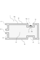
- FIG. 1 is a cross-sectional view showing a schematic configuration of a storage container according to a first embodiment.
- FIG. 1 is a schematic perspective view of a storage container according to a first embodiment;
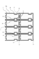
- FIG. 2 is a schematic cross-sectional view showing an example of a storage state of the storage container according to the first embodiment.
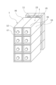
- FIG. 2 is a schematic perspective view showing an example of a storage state of the storage container according to the first embodiment.
- FIG. 11 is a schematic cross-sectional view showing a state in which a storage container according to another example of the first embodiment is fitted.
- FIG. 11 is a schematic cross-sectional view showing a state in which a storage container according to another example of the first embodiment is fitted.
- FIG. 11 is a schematic configuration diagram of a hydrogen generation system according to a second embodiment.
- FIG. 11 is a cross-sectional view showing a schematic configuration of a storage container according
- a first embodiment will be described with reference to Figs. 1 to 5.
- hydrogen has been attracting attention as an alternative energy source to fossil fuels. This is because, unlike fossil fuels, hydrogen does not generate carbon dioxide, a type of greenhouse gas that leads to global warming, when burned.
- One of the systems that use hydrogen as an energy source that has been put into practical use is a fuel cell vehicle.
- a fuel cell vehicle is a vehicle that generates electricity using hydrogen as a raw material and runs by driving an electric motor with the generated electricity.
- hydrogen which is an energy source
- the hydrogen tank stores hydrogen by compressing it at a high pressure, for example, 70 MPa (700 times atmospheric pressure).
- the volumetric energy density of hydrogen is about 1/3000 of that of gasoline, so even if a 70 MPa hydrogen tank is used, only about 1/5 of the energy of gasoline can be extracted from the same volume. For this reason, fuel cell vehicles that use hydrogen tanks generally require more frequent energy refueling than cars that use gasoline.
- hydrogen carriers various substances that can transport hydrogen at a higher energy density than hydrogen tanks (i.e., hydrogen carriers) are being considered.
- hydrogen carriers such as ammonia, methylcyclohexane, and sodium borohydride are known as hydrogen carriers, and hydrogen carriers are transported instead of hydrogen itself, and hydrogen is extracted from the hydrogen carrier when it is to be used.
- metal hydrides such as sodium borohydride are widely known, from which hydrogen can be easily extracted by adding water.
- As a method for obtaining hydrogen by hydrolysis of sodium borohydride a method for dissolving sodium borohydride in water and using it as an aqueous solution is known.
- a larger amount of water than the theoretically required amount shown in the reaction formula is required, and there is a problem that the actual volumetric energy density is reduced. Therefore, in this embodiment, as described later, hydrogen is generated by adding a liquid containing water to the hydrogen carrier in the hydrogen generation device (specifically, by pouring a liquid containing water onto the hydrogen carrier).
- hydrogen carriers that generate hydrogen when a liquid containing water is applied.
- solid metal hydrides such as sodium borohydride, potassium borohydride, lithium borohydride, zinc borohydride, lithium aluminum hydride, sodium aluminum hydride, magnesium aluminum hydride, calcium aluminum hydride, magnesium hydride, lithium hydride, sodium hydride, and calcium hydride, and metal powders such as aluminum, zinc, calcium, and magnesium can be used.
- Organic hydrides such as methylcyclohexane, cyclohexane, and decalin can also be used.
- Additives such as reaction accelerators and desiccants can also be used together with the hydrogen carrier.
- the hydrogen carrier of this embodiment may be either solid or liquid, but is preferably solid.
- a solid hydrogen carrier a solid such as a powder or granule is preferable, but a solid such as a sheet, pellet, or paste can also be used.
- a powder a particle size of about 10 ⁇ m to 10 mm can be used, and a particle size of about 10 ⁇ m to 3 mm, and even more preferably a particle size of about 10 ⁇ m to 100 ⁇ m.
- the hydrogen carrier of this embodiment is one that generates by-products (reaction products) other than hydrogen, such as liquid, gel, or solid, after hydrogen is generated in a chemical reaction.
- sodium borohydride powder with an average particle size of 50 ⁇ m is used as the solid hydrogen carrier.
- the powdered sodium borohydride reacts with water to generate hydrogen.
- the reacted sodium borohydride changes into sodium metaborate, which is a by-product.
- Water that is not used in the reaction remains as it is.
- This reaction can be expressed by the following chemical formula. NaBH4 (sodium borohydride) + 2H2O (water) ⁇ NaBO2 (sodium metaborate) + 4H2 (hydrogen) ... (1)
- This reaction (chemical formula (1)) is known to be accelerated by Raney catalysts made from metals such as nickel, cobalt, and copper, and acidic solutions such as citric acid and acetic acid.
- Raney catalysts made from metals such as nickel, cobalt, and copper, and acidic solutions such as citric acid and acetic acid.
- the by-product will be a liquid sodium metaborate solution or a gel-like sodium borate hydrate.
- liquid containing water in this embodiment is not particularly limited as long as it is a liquid that reacts with the hydrogen carrier when applied and generates hydrogen. That is, the liquid containing water may be water alone. In addition, two or more types of liquid containing water may be prepared. By preparing two or more types of liquid containing water, the rate of hydrogen generation can be adjusted.
- the water-containing liquid may contain a water-soluble organic solvent.
- a water-soluble organic solvent examples include alcohols, polyalkylene glycols, glycol ethers, nitrogen-containing compounds, and sulfur-containing compounds. Two or more selected from these may be mixed and used.
- a water-soluble organic solvent By including a water-soluble organic solvent, it is possible to adjust the surface tension and the boiling and melting points of the water-containing liquid, optimizing the reaction with the hydrogen carrier.
- Surfactants can be added to liquids that contain water. Using a surfactant can reduce the surface tension of the liquid that contains water, increasing the contact area with the hydrogen carrier and allowing for an efficient reaction.
- the aqueous liquid may contain a water-soluble acidic substance.
- the acidic substance acts as a positive catalyst in the reaction between the aqueous liquid and the hydrogen carrier.
- the speed at which hydrogen is generated can be adjusted by adjusting the amount of the aqueous liquid containing the acidic substance. In particular, the speed at which hydrogen is generated can be increased by making the pH obtained by the aqueous liquid and the hydrogen carrier less than 9.0.
- acids include, but are not limited to, various acids such as hydrochloric acid, sulfuric acid, nitric acid, boric acid, and organic acids.
- the water-containing liquid may contain a water-soluble basic substance.
- the basic substance acts as a negative catalyst in the reaction between the water-containing liquid and the hydrogen carrier.
- the speed at which hydrogen is generated can be adjusted by adjusting the amount of the liquid containing the basic substance. In particular, the speed at which hydrogen is generated can be slowed down by setting the pH obtained by the water-containing liquid and the hydrogen carrier to 9.0 or higher.
- bases include, but are not limited to, various bases such as sodium hydroxide, potassium hydroxide, and aqueous ammonia.
- the liquid containing water may contain a buffer solution.
- the buffer solution acts to suppress pH changes during the reaction between the liquid containing water and the hydrogen carrier.
- the speed at which hydrogen is generated can be adjusted by adjusting the amount of the liquid containing the buffering agent.
- buffer solutions include, but are not limited to, phosphate buffer, glycine buffer, Good's buffer, Tris buffer, and ammonia buffer.
- liquids containing water may contain various additives such as antifoaming agents, pH adjusters, viscosity adjusters, rust inhibitors, preservatives, antifungal agents, antioxidants, and anti-reducing agents, as necessary.
- Fig. 1 is a block diagram showing a schematic configuration of the hydrogen generation system 100 of this embodiment.
- the hydrogen generation system 100 includes a hydrogen carrier storage container 1, a hydrogen generation device 32, a water supply unit 33, and a fuel cell system 35.
- the hydrogen carrier storage container 1 is a container capable of storing a hydrogen carrier (sodium borohydride in this embodiment) and is a container that can be attached and detached to the hydrogen generation device 32.
- the filled hydrogen carrier is sent to the hydrogen generation section of the hydrogen generation device 32 by its own weight, and the supply amount can be adjusted by an opening and closing valve attached to the hydrogen generation section side.
- the storage container 1 also includes a relief valve 11 for releasing hydrogen gas generated inside to the outside, and a filter 13.
- the filter 13 is provided between the relief valve 11 and the inside of the storage container 1. This filter 13 allows hydrogen gas to pass through but does not allow the hydrogen carrier inside the container to pass through. A detailed explanation of the storage container 1 will be given later.
- the water supply unit 33 has the function of being able to supply "liquid containing water" from a water supply, a water tank, etc. to the hydrogen generation device 32, and a filter or the like is installed in the flow path to remove foreign matter, etc. In addition, it may have a function of adjusting the temperature of the liquid containing water being supplied, such as a heater or chiller, for the purpose of promoting and stabilizing the hydrolysis reaction.
- the hydrogen generating device 32 has a hydrogen generating section to which the hydrogen carrier is supplied from the storage container 1 and a liquid containing water is supplied from the water supply unit 33.
- the hydrogen carrier and the liquid containing water are mixed in the hydrogen generating section, causing a hydrolysis reaction to occur and generating hydrogen and by-products.
- the hydrogen generated in the hydrogen generation device 32 is sent to the fuel cell system 35.
- the fuel cell system 35 generates electricity using the hydrogen generated in the hydrogen generation device 32, and is an example of a device that utilizes the hydrogen generated in the hydrogen generation device 32.
- the by-product generated during hydrogen generation (sodium metaborate in this embodiment) is collected in a collection container (not shown).
- this hydrogen generation system 100 first, after the hydrogen carrier is injected into the storage container 1, if hydrogen is not generated, or if hydrogen is generated but does not exceed a threshold value set for safety reasons, it is delivered directly to the hydrogen generation device 32. Then, the hydrogen carrier is supplied from the storage container 1, and a liquid containing water is supplied from the water supply unit 33 to the hydrogen generation device 32, where hydrogen gas and by-products are produced.
- the relief valve 11 will automatically open and release the excess hydrogen from inside the storage container 1 to the outside.
- the storage container 1 for the hydrogen carrier has a storage section 14 for storing the hydrogen carrier, and has a cylindrical shape with a polygonal cross section perpendicular to the longitudinal direction.
- the cross section perpendicular to the longitudinal direction has a rectangular prism shape.
- the cross section perpendicular to the longitudinal direction of the storage container 1 may have other shapes such as a pentagon, hexagon, or octagon in addition to a rectangle.
- the storage container 1 has a flat surface 16 on at least a portion of the outer wall surface, and when stacked vertically or arranged horizontally, the flat surfaces 16 of adjacent storage containers 1 (flat surfaces) face each other and come into contact or close proximity, allowing multiple storage containers 1 to be arranged in a space-saving manner.
- the storage container 1 is preferably in the shape of a rectangular prism that allows efficient stacking in the up-down, front-back, and left-right directions, and as long as this is met, shapes such as a pentagonal prism, hexagonal prism, or octagonal prism may be used.
- the storage container 1 be made of metal or a resin container with anti-static measures. This will prevent hydrogen gas from igniting due to the metal even if it is generated inside. As a measure to dehumidify the inside of the storage container 1, there is no problem with sticking a desiccant or similar to the inner wall of the container. This will suppress the reaction between the hydrogen carrier and water inside the storage container 1, and suppress the generation of hydrogen gas.
- Such a storage container 1 has a planar portion 16 as a first planar portion, a planar portion 17 as a second planar portion, a recess 15 as a first recess, a relief valve 11, a filter 13, an opening 12, and a recess 18 as a second recess.
- the planar portions 16 are provided on both sides of the outer wall surface of the storage container 1 in at least one of the up-down, left-right, and front-to-back directions when the storage container 1 is installed. By arranging the planar portions 16 in this manner, it is possible to line up the storage containers 1 so that the planar portions 16 are abutting or close to each other.
- a pair of flat surfaces 16 are provided on the outer wall surface of the storage container 1 in at least two directions among the up-down direction, the left-right direction, and the front-to-rear direction when the storage container 1 is installed.
- the flat surfaces 16 By arranging the flat surfaces 16 in this manner, it is possible to line up the storage containers 1 so that the flat surfaces 16 abut or are close to each other in multiple directions.
- the storage container 1 has a rectangular prism shape with a cross section perpendicular to the longitudinal direction, and therefore a pair of flat surfaces 16 is provided in each of the up-down direction and the left-right direction when the storage container 1 is installed.
- the longitudinal direction of the storage container 1 is the front-to-rear direction.
- the storage containers 1 can be stacked vertically with their flat surfaces 16 abutting or close to each other, and can also be arranged side by side in the horizontal direction with their flat surfaces 16 abutting or close to each other. Even if the orientation of the storage container 1 is changed so that the above-mentioned vertical direction becomes the horizontal direction and the horizontal direction becomes the vertical direction, the storage containers 1 can be stacked vertically and can also be arranged side by side in the horizontal direction. The same applies to the relationship between the vertical direction and the front-to-back direction, and the relationship between the left-to-right direction and the front-to-back direction.
- the storage container 1 of this embodiment has a flat surface 17 on both sides in the front-to-rear direction. That is, both longitudinal ends of the storage container 1 also have flat surfaces 17. That is, the flat surfaces 17 are provided at positions on the outer wall surface of the storage container 1 that are different from the flat surfaces 16, and in this embodiment, both front-to-rear sides of the storage container 1 are flat surfaces 17.
- the storage containers 1 can be arranged side by side so that the flat surfaces 17 abut or are close to each other in the front-to-rear direction.
- An opening 12 is formed in one of the flat surfaces 17 on both sides in the front-rear direction.
- the opening 12 connects the inside and outside of the storage section 14, and is provided for injecting the hydrogen carrier into the storage section 14 or discharging it from the storage section 14.
- a recess 18 is formed in part of this flat surface 17, which is recessed inward more than the other parts. The opening 12 is provided within the recess 18.
- the opening 12 is formed to fit within the recess 18.
- the opening 12 can also be connected without any gaps to the hydrogen carrier inlet of the hydrogen generation device 32, and is structured to be able to supply the hydrogen carrier filled in the storage section 14 to the hydrogen generation section of the hydrogen generation device 32 without leakage.
- the opening 12 can also be connected without any gaps to the inlet of an injection device (not shown) for injecting the hydrogen carrier into the storage container 1.
- the opening 12 is closed by a lid (not shown), for example, after the hydrogen carrier is stored in the storage container 1.
- the recess 18 has a depth such that even when the opening 12 is closed with a lid, the lid does not protrude from the recess 18. Therefore, even if multiple storage containers 1 are arranged in a line in the front-to-rear direction so that the flat surface portion 17 on which the recess 18 is formed and the flat surface portion 17 on which the recess 18 is not formed are in contact or close to each other, the opening 12 and the lid closing the opening 12 will not interfere with the opposing flat surface portion 17.
- the recess 15 is formed in a portion of at least one of the pair of flat surfaces 16.
- the recess 15 is formed so as to be recessed inward relative to the other portion 16a of the flat surface 16, and so as to be at least partially connected to the outside of the flat surface 16 in the direction along the flat surface 16.
- the recess 15 is formed so as to be recessed all around the same location in the longitudinal direction of the storage container 1. That is, when the storage container 1 is installed, a recess 15 is formed in each of the pair of flat surfaces 16 in the up-down direction, and a recess 15 is also formed in each of the pair of flat surfaces 16 in the left-right direction. These four recesses 15 are continuous all around the storage container 1.
- the recess 15 is formed in at least one of the flat surfaces 16.
- the right or left side, or the front or rear side of the recess 15 may communicate with the outside.
- the recess 15 communicates with the outside on both the left and right sides or both the front and rear sides. Note that a part of the recess 15 communicates with the outside means that even if a part of the recess 15 is open and the side facing the bottom surface of the recess 15 is blocked, gas can pass between the inside and outside of the recess 15.
- gas can flow between the inside and outside of the recess 15 in the left and right directions even if the upper side of the recess 15 is blocked.
- the recess 15 is formed in at least two of the multiple flat surfaces 16.
- the recess 15 may be formed in each of the pair of flat surfaces 16 described above.
- the recess 15 may be formed in at least two of these flat surfaces 16.
- the recess 15 may be formed in the upper flat surface 16 and the right or left flat surface 16.
- recesses 15 are formed in each of a pair of flat surfaces 16 on both sides in the vertical direction and a pair of flat surfaces 16 on both sides in the horizontal direction. This allows the space formed by the opposing recesses 15 between adjacent storage containers 1 to be connected to the outside of the area in which the storage containers 1 are arranged, regardless of how the storage containers 1 are arranged.
- the relief valve 11 is provided inside the recess 15 (inside the recess) and automatically opens when the pressure inside the storage unit 14 exceeds a predetermined value to release the gas inside the storage unit 14 to the outside.
- the relief valve 11 only needs to be provided in at least one of the multiple recesses 15. As shown in FIG. 2, the relief valve 11 is formed on the bottom surface 15a of the recess 15 and is provided so as to block the communication port 15b that communicates with the storage unit 14. That is, the relief valve 11 is provided on the bottom surface 15a of the recess 15.
- the recess 15 has a depth such that the relief valve 11 installed inside does not protrude outside the recess 15. Therefore, even if the storage containers 1 are stacked vertically or lined up horizontally or front-to-back with the flat surfaces 16 on which the recesses 15 are formed abutting or close to each other, the relief valve 11 will not interfere with parts of the adjacent storage containers 1. Furthermore, the opening and closing operation of the relief valve 11 is not hindered.
- the hydrogen carrier in the storage container 1 will react with a liquid containing water, generating hydrogen gas.
- This hydrogen gas may then fill the storage section 14, causing the storage container 1 to be unable to withstand the pressure of the expanding hydrogen gas and burst.
- the relief valve 11 will automatically open due to the pressure, releasing the excess hydrogen gas to the outside, thereby preventing damage to the storage container 1.
- the above-mentioned filter 13 is provided at the communication port 15b between the relief valve 11 and the storage unit 14.
- the filter 13 is configured to allow hydrogen gas to pass through but not the hydrogen carrier in the storage unit 14. This prevents the hydrogen carrier from leaking to the outside through the communication port 15b during transportation of the storage container 1, and also makes it possible to discharge part of the hydrogen gas to the outside through the filter 13 and relief valve 11 provided at the communication port 15b when the pressure of the hydrogen gas in the storage unit 14 increases.
- the relief valve 11 may be installed in at least one of the recesses 15 formed on the four faces perpendicular to the longitudinal direction of the storage container 1, but multiple recesses 15 may also be provided in the other faces. Furthermore, a recess may be formed in one or both of the flat surfaces 17 on both sides of the storage container 1 in the front-to-rear direction, and the relief valve 11 may be provided in this recess. For example, the relief valve 11 may be provided in the recess 18 in which the above-mentioned opening 12 is formed.
- one relief valve 11 is provided in one recess 15, but it is preferable to provide a relief valve 11 in each of two or more recesses 15.
- a relief valve 11 may be provided in each of the multiple recesses 15.
- the relief valve 11 is provided in each of the multiple recesses 15. That is, the relief valve 11 may be provided in each of the recesses 15 formed in the pair of flat surfaces 16 on both sides in any of the up-down, left-right, and front-to-rear directions, or may be provided in each of the recesses 15 formed in the multiple flat surfaces 16 regardless of the direction. For example, one relief valve 11 may be provided on the upper side and one on the right or left side when the storage container 1 is installed.
- relief valves 11 will be provided in all of the recesses 15 on the upper, lower, right, and left sides when the storage container 1 is in the installed state.
- the relief valve 11 opens automatically when the pressure inside the storage container 1 exceeds a predetermined value, so at least one is sufficient; however, it is preferable to provide a relief valve 11 in each of the recesses 15 of the multiple flat surfaces 16 as described above, from the viewpoint of more reliably discharging hydrogen gas from the relief valve 11.
- the relief valve 11 is located on the lower side in the installed state, hydrogen gas may not be easily discharged from the lower relief valve 11 because the specific gravity of hydrogen gas is smaller than that of air. In this case, if there are other relief valves 11 on the upper, right, left, etc. side in the installed state, hydrogen gas can be efficiently discharged from these relief valves 11.
- the relief valve 11 is located on the upper side when the storage container 1 is installed. Therefore, by providing the relief valve 11 on the upper, lower, right, or left side as described above, when installing the storage container 1, it is possible to position any of the relief valves 11 on the upper side without having to worry about the orientation of the storage container 1.
- FIG. 4 and 5 each show an example of a storage state in which a plurality of storage containers 1 are arranged side by side.
- the recesses 15 are formed so as to be continuous with each other in four directions, namely, the up-down direction and the left-right direction, in the installed state, and around the entire circumference.
- a relief valve 11 is provided in the upper recess 15 in the installed state.
- Figure 4 shows a case where multiple storage containers 1 are stacked vertically and arranged side by side in the front-to-back direction. Since the openings 12 of the storage containers 1 are formed to fit within the recesses 18 in the front-to-back direction, it is possible to arrange the storage containers 1 with no gaps in the front-to-back direction so that the flat surfaces 17 of the storage containers 1 arranged side by side in the front-to-back direction abut against each other.
- multiple storage containers 1 can be stacked vertically with no gaps so that the upper flat surface 16 of the lower storage container 1 abuts the lower flat surface 16 of the upper storage container 1.
- the recess 15 formed in the upper flat surface 16 of the lower storage container 1 faces the recess 15 formed in the lower flat surface 16 of the upper storage container 1, and a space penetrating in the left-right direction is formed between these two recesses 15.
- a relief valve 11 is provided in the recess 15 of the lower storage container 1, and hydrogen gas discharged from the relief valve 11 is discharged through this space to the outside of the area where multiple storage containers 1 are stacked.
- FIG. 5 shows a case where multiple storage containers 1 are stacked vertically and arranged side by side.
- the relationship of each part when the storage containers 1 are stacked vertically is as described in FIG. 4.
- multiple storage containers 1 can be arranged horizontally without gaps so that the left flat surface 16 of the storage container 1 on the right side abuts the right flat surface 16 of the storage container 1 on the left side.
- the recess 15 formed on the left flat surface 16 of the storage container 1 on the right side faces the recess 15 formed on the right flat surface 16 of the storage container 1 on the left side, and a space penetrating in the vertical direction is formed between these two recesses 15.
- the hydrogen gas discharged from the relief valve 11 of the lower storage container 1 is discharged to the outside of the area where multiple storage containers 1 are stacked and laid out in the horizontal direction through the horizontal space formed between a pair of recesses 15 facing each other vertically and the vertical space formed between a pair of recesses 15 facing each other horizontally.
- recesses 15 are formed in the flat surfaces 16 that abut or are close to each other, and relief valves 11 are provided in the recesses 15.
- the recesses 15 are formed so that at least a portion of them communicates with the outside of the flat surface 16 in the direction along the flat surface 16. For this reason, hydrogen gas discharged from the relief valve 11 is easily discharged to the outside from the portion that communicates the recesses 15 with the outside. For this reason, even if the storage containers 1 are stored by stacking them vertically or laying them out in the left-right or front-back directions, it is possible to suppress an increase in pressure inside the storage containers 1. In addition, it is possible to prevent hydrogen gas discharged from the relief valves 11 from accumulating between multiple storage containers 1, improving the safety of the storage location.
- FIG. 6A Another example of the first embodiment will be described with reference to Figures 6A and 6B.
- this example is provided with a fitting portion 40 that fits together a plurality of stacked or lined up storage containers 1A, 1B.
- the fitting portion 40 is provided on the flat surface portion 16, and can be fitted into the fitting portion 40 provided on the other storage container 1B when the storage container 1A is installed so that the flat surface portions 16 of the storage container 1A and the other storage container 1B face each other.
- the fitting portion 40 has a protruding portion 41 protruding from the planar portion 16 and a bent portion 42 bent from the protruding portion 41 in a direction approximately parallel to the planar portion 16.
- Such fitting portions 40 may be provided on both planar portions 16 in the up-down direction in the installed state, on both planar portions 16 in the left-right direction, or on all planar portions 16 in the up-down and left-right directions.
- the fitting portion 40 may be provided on the planar portion 17 by, for example, making the recess 18 on the side where the opening 12 is formed smaller, or by providing the opening 12 on a different surface.
- multiple fitting portions 40 are provided on all planar portions 16 in the up-down and left-right directions.
- the mating portions 40 are shifted from each other in the front-to-rear direction.
- one of the storage containers 1A, 1B is shifted from the other in the front-to-rear direction to allow the mating portions 40 to fit together.
- the bent portions 42 of each container overlap vertically, preventing the storage containers 1A, 1B from separating in the vertical direction.
- the tip of the bent portion 42 of one container faces the protruding portion 41 of the other container, preventing the storage containers 1A, 1B from shifting in the front-to-rear direction.
- the storage containers 1A, 1B are arranged side by side in the left-right direction, and because the bent portions 42 of each container overlap each other in the left-right direction, the storage containers 1A, 1B can be prevented from moving apart in the left-right direction.
- the storage containers 1A, 1B can be fixed to each other. This makes it possible to prevent the load from collapsing due to vibration or the containers from accidentally shifting due to the action of external forces when the storage containers 1A, 1B are stacked or lined up for transport or storage.
- the second embodiment will be described with reference to Figures 7 and 8.
- the storage container 1 for storing the hydrogen carrier was described.
- the storage container 1C is configured to be capable of storing by-products as well. Since the other configurations and functions are similar to those of the first embodiment described above, the same reference numerals are used for similar configurations, and descriptions thereof will be omitted or simplified. The following description will focus on the points that are different from the first embodiment.
- This embodiment is an example of a case where the device is used not only to deliver and supply the raw material (hydrogen carrier) to the hydrogen generation device 32, but also as a collection container for the by-product (sodium metaborate is the by-product when the hydrogen carrier is sodium borohydride) generated after the hydrogen generation reaction in the hydrogen generation device 32.
- FIG. 7 is a block diagram showing a schematic configuration of the hydrogen generation system 100A of this embodiment.
- the hydrogen generation system 100A includes a storage container 1C for the hydrogen carrier and by-products, a hydrogen generation device 32, a water supply unit 33, and a fuel cell system 35.
- the configuration other than the storage container 1C is the same as that shown in FIG. 1.
- the hydrogen carrier is first injected into the storage container 1C, and if hydrogen is not generated, or if hydrogen is generated but does not exceed a threshold value set in consideration of safety, it is delivered directly to the hydrogen generation device 32. Then, the hydrogen carrier is supplied from the storage container 1C and a liquid containing water is supplied from the water supply unit 33 to the hydrogen generation device 32, where hydrogen gas and by-products are generated.
- the hydrogen generation reaction in the hydrogen generator 32 is complete and the storage container 1C is used as a by-product collection container, if no hydrogen is generated from the collected by-products, or if hydrogen is generated but does not exceed a threshold set for safety reasons, it is collected directly into the storage container 1C. If hydrogen is generated from the by-products for some reason and the air pressure inside the storage container 1C exceeds a specified value as a result, the hydrogen gas relief valve 11 automatically opens, releasing the excess hydrogen outside the container.
- the storage container 1C has a first storage section 14A and a second storage section 23.
- the first storage section 14A is a section for storing the hydrogen carrier
- the second storage section 23 is a section for storing by-products generated together with hydrogen when the hydrogen carrier is reacted with a liquid containing water.
- the second storage section 23 does not allow the by-products to pass through to the first storage section 14A, but allows the gas generated in the second storage section 23 to pass through to the first storage section 14A.
- the second storage section 23 is an elastic bag-like member, and is disposed inside the first storage section 14A.
- the material of the second storage section 23 may be fiber or rubber.
- the storage container 1C is provided with a flat surface 16, a recess 15, a relief valve 11, etc., as in the first embodiment described above.
- a recess 18 is formed in the flat surface 17 on one side in the front-to-rear direction, and an opening 12 is formed for injecting or discharging the hydrogen carrier into or from the first storage section 14A.
- a flat surface 20 is provided as a third flat surface on the other side in the front-to-rear direction.
- the flat surface 20 is provided at a position different from the flat surface 16 as the first flat surface on the outer wall surface of the storage container 1C, and in this embodiment, it is provided on the surface opposite the side on which the opening 12 is formed.
- the flat surface 20 abuts or is adjacent to the flat surface 17 when the storage containers 1C are arranged in the front-to-rear direction.
- a recess 24 is formed as a third recess in a portion of the flat portion 20 so as to be recessed inward more than the other portions.
- An opening 21 is formed in the recess 24 as a by-product opening that connects the inside and outside of the second storage portion 23 and is used to inject or discharge by-products into or from the second storage portion 23.
- the opening 21 is formed to fit within the recess 24.
- the opening 21 can be connected without any gaps to the by-product discharge port of the hydrogen generation device 32, and is configured to be able to recover by-products from the hydrogen generation device 32 without leakage.
- the opening 21 is also configured to be connected without any gaps to a recovery port of a recovery device (not shown) for recovering by-products in the second storage portion 23.
- the second storage section 23 which is a bag-like elastic material, is connected to the opening 21, and the by-products collected through the opening 21 are sent to the second storage section 23.
- the second storage section 23 expands due to its elasticity in accordance with the volume of the collected by-products.
- the second storage section 23 shrinks due to its elasticity.
- the by-products collected in the second storage section 23 are by-products resulting from the reaction in the hydrogen generation device 32, and may contain moisture or may be mixed with unreacted residual hydrogen carriers. This may result in the generation of residual hydrogen gas within the second storage section 23.
- the second storage section 23 is designed to have a bag-like elasticity, and in the unlikely event that hydrogen gas is generated from the by-products, only hydrogen gas can pass through, while the by-products themselves are impermeable. Hydrogen gas that has permeated from the second storage section 23 to the first storage section 14A is discharged to the outside through the relief valve 11.
- the storage container 1C even if the storage container 1C is used to store by-products, hydrogen gas generated inside can be discharged from the relief valve 11.
- the increase in pressure inside the storage container 1C can be suppressed.
- hydrogen gas discharged from the relief valve 11 can be prevented from accumulating between multiple storage containers 1C, improving the safety of the storage location.
- the storage container 1C of this embodiment may also be provided with the fitting portion 40 described in Figures 6A and B.
- the storage container 1 for the hydrogen carrier has been described.
- by-products may be stored in the storage container 1. That is, the storage container 1 for the hydrogen carrier may be used as a storage container for the by-products. In this case, the by-products are stored in the storage section 14 of the storage container 1.
- the hydrogen carrier storage container and by-product storage container of the present invention are suitable as storage containers for storing hydrogen carriers and by-products.
Landscapes
- Engineering & Computer Science (AREA)
- Mechanical Engineering (AREA)
- General Engineering & Computer Science (AREA)
- Filling Or Discharging Of Gas Storage Vessels (AREA)
Abstract
一対の平面部16は、貯蔵容器1の外壁面のうち、貯蔵容器1の設置状態における上下方向、左右方向及び前後方向のうちの少なくとも何れかの方向に関して両側に設けられている。凹部15は、一対の平面部16の少なくとも何れかの平面部16の一部に形成され、平面部16の他の部分16aよりも内側に凹むように、且つ、平面部16に沿った方向に関して少なくとも一部が平面部16の外側と連通するように形成されている。逃し弁11は、凹部15内に設けられ、水素キャリアを貯蔵するための貯蔵部14の内部の圧力が所定値を超えると自動的に開いて、貯蔵部14の内部の気体を外部に逃す。これにより、水素キャリアや副生成物を貯蔵する貯蔵容器1を上下方向に重ねたり、左右方向や前後方向に敷き詰めたりするように保管しても、貯蔵容器1内の圧力の上昇を抑制できる。
Description
本発明は、水素キャリアや副生成物を貯蔵するための水素キャリアの貯蔵容器及び副生成物の貯蔵容器に関する。
ガスを貯蔵する貯蔵容器として、上面及び下面が平らであり、上下に積み重ねが可能な構成が提案されている(特許文献1)。
ここで、水素キャリアと水を含む液体とを反応させることで水素を発生する装置が従来から知られている。また、この際、水素と共に副生成物が生成されることも従来から知られている。このような水素キャリアや副生成物を貯蔵容器に貯蔵した場合、貯蔵されている環境によって、貯蔵容器内で水素などの気体が発生する虞がある。この場合、貯蔵容器内の圧力が高まり、貯蔵容器が破裂してしまう虞があるため、貯蔵容器の内部の気体を外部に逃す逃し弁を設けることが考えられる。
しかしながら、貯蔵容器を上下方向に重ねたり、左右方向や前後方向に敷き詰めたりするように保管した場合、逃し弁が塞がれて、貯蔵容器の内部から気体が十分に排出されず、貯蔵容器内の圧力が上昇してしまう虞がある。
本発明は、水素キャリアや副生成物を貯蔵する貯蔵容器を上下方向に重ねたり、左右方向や前後方向に敷き詰めたりするように保管しても、貯蔵容器内の圧力の上昇を抑制できる構成を提供することを目的とする。
本発明の水素キャリアの貯蔵容器は、水素キャリアを貯蔵可能な水素キャリアの貯蔵容器であって、水素キャリアを貯蔵するための貯蔵部と、前記貯蔵容器の外壁面のうち、前記貯蔵容器の設置状態における上下方向、左右方向及び前後方向のうちの少なくとも何れかの方向に関して両側に設けられた一対の平面部と、前記一対の平面部の少なくとも何れかの平面部の一部に形成された凹部であって、該平面部の他の部分よりも内側に凹むように、且つ、該平面部に沿った方向に関して少なくとも一部が前記平面部の外側と連通するように形成された凹部と、前記凹部内に設けられ、前記貯蔵部の内部の圧力が所定値を超えると自動的に開いて、前記貯蔵部の内部の気体を外部に逃す逃し弁と、を備える。
また、本発明の副生成物の貯蔵容器は、水素キャリアと水を含む液体とを反応させた際に水素と共に生成される副生成物を貯蔵可能な副生成物の貯蔵容器であって、副生成物を貯蔵するための貯蔵部と、前記貯蔵容器の外壁面のうち、前記貯蔵容器の設置状態における上下方向、左右方向及び前後方向のうちの少なくとも何れかの方向に関して両側に設けられた一対の平面部と、前記一対の平面部の少なくとも何れかの平面部の一部に形成された凹部であって、該平面部の他の部分よりも内側に凹むように、且つ、該平面部に沿った方向に関して少なくとも一部が前記平面部の外側と連通するように形成された凹部と、前記凹部内に設けられ、前記貯蔵部の内部の圧力が所定値を超えると自動的に開いて、前記貯蔵部の内部の気体を外部に逃す逃し弁と、を備える。
本発明によれば、水素キャリアや副生成物を貯蔵する貯蔵容器を上下方向に重ねたり、左右方向や前後方向に敷き詰めたりするように保管しても、貯蔵容器内の圧力の上昇を抑制できる。
<第1の実施形態>
第1の実施形態について、図1ないし図5を用いて説明する。まず、化石燃料に代わるエネルギー源として水素が注目されている。水素は化石燃料と異なり、燃焼時に地球温暖化につながる温室効果ガスの一種である二酸化炭素等を発生させないためである。水素をエネルギー源として用いるシステムとして実用化されているものの一つに、燃料電池車がある。燃料電池車は、水素を原料として発電し、発電した電気で電動機を動かして走る自動車である。燃料電池車の多くは、エネルギー源である水素を水素タンクに格納し、水素タンクから出た水素を燃料電池に入れて発電する。水素タンクは水素を、例えば70MPa(大気圧の700倍)などの高圧で圧縮して貯蔵するものである。
第1の実施形態について、図1ないし図5を用いて説明する。まず、化石燃料に代わるエネルギー源として水素が注目されている。水素は化石燃料と異なり、燃焼時に地球温暖化につながる温室効果ガスの一種である二酸化炭素等を発生させないためである。水素をエネルギー源として用いるシステムとして実用化されているものの一つに、燃料電池車がある。燃料電池車は、水素を原料として発電し、発電した電気で電動機を動かして走る自動車である。燃料電池車の多くは、エネルギー源である水素を水素タンクに格納し、水素タンクから出た水素を燃料電池に入れて発電する。水素タンクは水素を、例えば70MPa(大気圧の700倍)などの高圧で圧縮して貯蔵するものである。
エネルギー源としての水素の課題として、エネルギー密度が低いという点が挙げられる。水素の体積エネルギー密度はガソリンの約1/3000であり、70MPaの水素タンクを用いても、同じ体積からはガソリンの1/5程度のエネルギーしか引き出すことができない。そのため、一般的に、水素タンクを用いた燃料電池車は、ガソリンを用いた自動車よりも頻繁にエネルギー充填を行うことが要求される。
このため、水素タンクよりも高いエネルギー密度で水素を運ぶことができる物質(即ち、水素キャリア)として、様々な物質が検討されている。例えば、アンモニア、メチルシクロヘキサン、水素化ホウ素ナトリウムなどのボロハイドライドなどが水素キャリアとして知られており、水素そのものの代わりに水素キャリアを輸送し、利用時に水素キャリアから水素を取り出すということが行われている。
[水素キャリア]
水素キャリアの中でも、水を付与することで容易に水素を取り出すことができる水素化ホウ素ナトリウムのような金属水素化物が広く知られている。この水素化ホウ素ナトリウムを加水分解して水素を得る方法として、水素化ホウ素ナトリウムを水に溶解して水溶液として使用する方法が知られている。しかしこの方法の場合、反応式が示す理論上、必要な量より多量の水が必要になってしまい、実質の体積エネルギー密度が低下してしまうという問題がある。そこで、本実施形態では、後述するように、水素発生装置において水素キャリアに水を含む液体を付与して(具体的には、液体を水素キャリアに水を含む液体をかけて)水素を発生させている。
水素キャリアの中でも、水を付与することで容易に水素を取り出すことができる水素化ホウ素ナトリウムのような金属水素化物が広く知られている。この水素化ホウ素ナトリウムを加水分解して水素を得る方法として、水素化ホウ素ナトリウムを水に溶解して水溶液として使用する方法が知られている。しかしこの方法の場合、反応式が示す理論上、必要な量より多量の水が必要になってしまい、実質の体積エネルギー密度が低下してしまうという問題がある。そこで、本実施形態では、後述するように、水素発生装置において水素キャリアに水を含む液体を付与して(具体的には、液体を水素キャリアに水を含む液体をかけて)水素を発生させている。
水を含む液体を付与することで水素を発生する水素キャリアとしては、以下のものが挙げられる。例えば、水素化ホウ素ナトリウム、水素化ホウ素カリウム、水素化ホウ素リチウム、水素化ホウ素亜鉛、水素化アルミニウムリチウム、水素化アルミニウムナトリウム、水素化アルミニウムマグネシウム、水素化アルミニウムカルシウム、水素化マグネシウム、水素化リチウム、水素化ナトリウム、水素化カルシウムなどの固体の金属水素化物、アルミニウム、亜鉛、カルシウム、マグネシウムといった金属粉末等の1種もしくは、複数種混合したものが使用可能である。また、メチルシクロヘキサン、シクロヘキサン、デカリンといった有機ハイドライドなども使用可能である。また、水素キャリアと共に、反応促進剤、乾燥剤といったような添加剤を用いても良い。
また、本実施形態の水素キャリアは、固体でも液体でも特に制限はないが、固体であることが好ましい。固体の水素キャリアとしては、粉体や顆粒などの固体が望ましいが、シート状、ペレット状、ペースト状などの固体でも使用可能である。粉体としては、粒径10μm以上10mm以下程度のものが使用可能であり、粒径10μm以上3mm以下程度のもの、更には、粒径10μm以上100μm以下程度のものがより好ましい。また、シート状、ペレット状で用いる場合には、水を含む液体との反応性を高める観点で、表面粗し、多孔質処理などを施し、表面積を大きくし、水を含む液体との接触面積を多くすることが好ましい。
本実施形態の水素キャリアとしては、化学反応で水素が発生した後に、液体状、ゲル状、固体状などの水素以外の副生成物(反応生成物)が発生するものが対象となる。
本実施形態では、固体の水素キャリアとして、平均粒径50μmの水素化ホウ素ナトリウムの粉体を用いた。粉体の水素化ホウ素ナトリウムは、水と反応することで、水素を発生する。反応した水素化ホウ素ナトリウムは、副生成物であるメタホウ酸ナトリウムへと変化する。反応に使用されなかった水はそのまま残る。この反応を化学式で表すと、以下の通りである。
NaBH4(水素化ホウ素ナトリウム)+2H2O(水)
→NaBO2(メタホウ酸ナトリウム)+4H2(水素)・・・(1)
NaBH4(水素化ホウ素ナトリウム)+2H2O(水)
→NaBO2(メタホウ酸ナトリウム)+4H2(水素)・・・(1)
この反応(化学式(1))は、ニッケル、コバルト、銅などの金属から作られるラネー触媒や、クエン酸、酢酸などの酸性溶液により促進されることが知られている。また、本実施形態においては、加水分解反応を隅々まで効率よく行わせるために、(1)式より多量な水を投入する場合は、副生成物は液体状のメタホウ酸ナトリウム溶液、または、ゲル状のホウ酸ナトリウム水和物となる。
[水を含む液体]
本実施形態でいう「水を含む液体」は、液体を付与することで水素キャリアと反応し、水素を発生する液体であれば、特に制限はない。即ち、水を含む液体は水単体であってもよい。また、水を含む液体は、2種類以上用意しても良い。水を含む液体を2種類以上用意することにより、水素の発生速度を調節することができる。
本実施形態でいう「水を含む液体」は、液体を付与することで水素キャリアと反応し、水素を発生する液体であれば、特に制限はない。即ち、水を含む液体は水単体であってもよい。また、水を含む液体は、2種類以上用意しても良い。水を含む液体を2種類以上用意することにより、水素の発生速度を調節することができる。
水を含む液体は、水溶性有機溶剤を含むことができる。例えば、アルコール類、ポリアルキレングリコール類、グリコールエーテル類、含窒素化合物類、含硫黄化合物類などを挙げることができる。これらの中から選択した2種類以上のものを混合して用いることもできる。水溶性有機溶剤を含むことで、表面張力の調節や、水を含む液体としての沸点・融点の調節を行い、水素キャリアとの反応を最適化することができる。
水を含む液体には、界面活性剤を添加することができる。界面活性剤を用いることで水を含む液体の表面張力を下げることができ、水素キャリアとの接触面積を増やし、効率的な反応を行うことができる。
水を含む液体には、水溶性の酸性物質を含むことができる。酸性物質は、水を含む液体と水素キャリアとの反応において、正触媒として働く。酸性物質を含む液体の量を調節することで、水素の発生スピードを調節することができる。特に、水を含む液体と水素キャリアで得られるpHを9.0未満にすることで、水素発生スピードを速くすることができる。例えば、塩酸、硫酸、硝酸、ホウ酸、有機酸等各種の酸が挙げられるが、これに限定されない。
水を含む液体には、水溶性の塩基性物質を含むことができる。塩基性物質は、水を含む液体と水素キャリアとの反応において、負触媒として働く。塩基性物質を含む液体の量を調節することで、水素の発生スピードを調節することができる。特に、水を含む液体と水素キャリアで得られるpHを9.0以上にすることで、水素発生スピードを遅くすることができる。例えば、水酸化ナトリウム、水酸化カリウム、アンモニア水、等各種の塩基が挙げられるが、これに限定されない。
水を含む液体には、緩衝液を含むことができる。緩衝液は、水を含む液体と水素キャリアとの反応において、pH変化を抑える働きをする。緩衝剤を含む液体の量を調節することで、水素の発生スピードを調節することができる。例えば、リン酸緩衝液、グリシン緩衝液、グッド緩衝液、トリス緩衝液、アンモニア緩衝液などの各種緩衝液が挙げられるが、これらに限定されない。
水を含む液体には、上記成分以外にも必要に応じて、消泡剤、pH調整剤、粘度調整剤、防錆剤、防腐剤、防黴剤、酸化防止剤、還元防止剤など種々の添加剤を含有させてもよい。
[水素発生システム]
本実施形態の水素発生システム100について、図1を用いて説明する。図1は、本実施形態の水素発生システム100の概略構成を模式的に示したブロック図である。水素発生システム100は、水素キャリアの貯蔵容器1、水素発生装置32、水供給ユニット33、燃料電池システム35を備える。
本実施形態の水素発生システム100について、図1を用いて説明する。図1は、本実施形態の水素発生システム100の概略構成を模式的に示したブロック図である。水素発生システム100は、水素キャリアの貯蔵容器1、水素発生装置32、水供給ユニット33、燃料電池システム35を備える。
水素キャリアの貯蔵容器1は、水素キャリア(本実施形態では、水素化ホウ素ナトリウム)を収容できる容器であり、水素発生装置32に対し、着脱可能な容器となっている。充填された水素キャリアは、自重により、水素発生装置32の水素発生部に送られ、水素発生部側に付随している開閉弁で供給量が調整可能である。
また、貯蔵容器1は、内部で発生した水素ガスを外部に逃すための逃し弁11と、フィルタ13とを備える。フィルタ13は、逃し弁11と貯蔵容器1の内部との間に設けられている。このフィルタ13は、水素ガスは通過できるが容器内の水素キャリアは通過できないものである。貯蔵容器1の詳しい説明は後述する。
水供給ユニット33は、水道、水タンクなどから「水を含む液体」を水素発生装置32に供給可能な機能を持っており、異物等を取り除くために流路にはフィルタなどが設置されている。また、加水分解反応を促進させる、安定させるといった目的で、ヒーターやチラーといった供給する水を含む液体の温度を調節する機能があっても良い。
水素発生装置32は、水素発生部を有し、水素発生部に貯蔵容器1から水素キャリアが供給され、水供給ユニット33から水を含む液体が供給される。そして、水素発生部で水素キャリアと水を含む液体とを混合し、加水分解反応を起こさせて、水素と副生成物を発生させる。
水素発生装置32で発生した水素は、燃料電池システム35へ送られる。燃料電池システム35は、水素発生装置32で発生した水素を用いて発電を行うもので、水素発生装置32で発生した水素を利用する装置の一例を示している。水素発生時に生成される副生成物(本実施形態では、メタホウ酸ナトリウム)は、不図示の回収容器に回収される。
このような水素発生システム100においては、まず、水素キャリアを貯蔵容器1に注入後、水素が発生しない場合、或いは、発生しても安全性を考慮し設定した閾値を超えない場合は、そのまま水素発生装置32まで配送される。そして、貯蔵容器1から水素キャリアが、水供給ユニット33から水を含む液体が水素発生装置32に供給され、水素発生装置32において水素ガスと副生成物とが生成される。
何らかの要因で水素キャリアが貯蔵容器1の内部で反応して水素ガスが発生し、それにより貯蔵容器1内の圧力が所定値を超えた場合は、自動的に逃し弁11が開き、貯蔵容器1内から外部へ余分な水素を放出する仕組みになっている。
[水素キャリアの貯蔵容器]
次に、図2及びを用いて水素キャリアの貯蔵容器1について説明する。貯蔵容器1は、水素キャリアを貯蔵するための貯蔵部14を有し、長手方向に直交する断面形状が多角形状である筒状形状を有する。本実施形態では、図3に示すように、長手方向に直交する断面形状が四角形の角柱形状を有している。なお、貯蔵容器1の長手方向に直交する断面形状は、四角形以外に五角形や六角形、八角形など他の形状であっても良い。
次に、図2及びを用いて水素キャリアの貯蔵容器1について説明する。貯蔵容器1は、水素キャリアを貯蔵するための貯蔵部14を有し、長手方向に直交する断面形状が多角形状である筒状形状を有する。本実施形態では、図3に示すように、長手方向に直交する断面形状が四角形の角柱形状を有している。なお、貯蔵容器1の長手方向に直交する断面形状は、四角形以外に五角形や六角形、八角形など他の形状であっても良い。
後述するように、貯蔵容器1は、外壁面の少なくとも一部に平面部16を有して、鉛直方向に積み重ねたり、水平方向に敷き詰めるように並べたりした場合に、隣り合う貯蔵容器1の平面部16同士(平面部同士)が対向し、当接または近接することで、省スペースに複数の貯蔵容器1を配置できるようになっていれば良い。貯蔵容器1は、上下方向、前後方向及び左右方向に効率的に積載することが可能な角柱形状とすることが好ましく、これを満たせば、五角柱、六角柱、八角柱といった形状でも構わない。
また、貯蔵容器1は、静電気の帯電防止の観点から、金属製や静電気の対策を施した樹脂製の容器であることが好ましい。これにより、内部で水素ガスが発生しても製で金により引火することを防止できる。また、貯蔵容器1内の除湿対策として、容器の内壁に乾燥剤の類を張り付けたようなものでも特に問題はない。これにより、貯蔵容器1の内部で水素キャリアと水の反応を抑制し、水素ガスの発生を抑制できる。
このような貯蔵容器1は、第1平面部としての平面部16、第2平面部としての平面部17、第1凹部としての凹部15、逃し弁11、フィルタ13、開口部12、第2凹部としての凹部18を有する。平面部16は、貯蔵容器1の外壁面のうち、貯蔵容器1の設置状態における上下方向、左右方向及び前後方向のうちの少なくとも何れかの方向に関して両側に設けられている。このように平面部16を配置することで、互いの平面部16同士が当接又は近接するように貯蔵容器1を並べることが可能となる。
一対の平面部16は、貯蔵容器1の外壁面のうち、貯蔵容器1の設置状態における上下方向、左右方向及び前後方向のうちの少なくとも2方向にそれぞれ設けられていることが好ましい。このように平面部16を配置することで、複数の方向に沿って互いの平面部16同士が当接又は近接するように貯蔵容器1を並べることが可能となる。本実施形態では、貯蔵容器1は、長手方向に直交する断面形状が四角形の角柱形状を有しているため、設置状態における上下方向及び左右方向のそれぞれの方向に関して一対の平面部16が設けられている。なお、本実施形態では、貯蔵容器1の長手方向を前後方向とする。
このように、設置状態における上下方向及び左右方向のそれぞれの方向に関して一対の平面部16を設けることで、貯蔵容器1を互いの平面部16同士が当接又は近接するように上下方向に積み重ねることができると共に、左右方向にも互いの平面部16同士が当接又は近接するように貯蔵容器1を並べて配置することができる。また、上述の上下方向が左右方向に、左右方向が上下方向となるように貯蔵容器1の向きを変えても、同様に、貯蔵容器1を上下方向に積み重ねることができると共に、左右方向にも貯蔵容器1を並べて配置することができる。上下方向と前後方向の関係、左右方向と前後方向の関係についても同様である。
また、本実施形態の貯蔵容器1は、平面部17が前後方向の両側にそれぞれ設けられている。即ち、貯蔵容器1の長手方向両端部についても平面部17としている。即ち、平面部17は、貯蔵容器1の外壁面のうち、平面部16とは異なる位置に設けられており、本実施形態では、貯蔵容器1の前後方向両側を平面部17としている。そして、前後方向に互いの平面部17同士が当接又は近接するように貯蔵容器1を並べて配置できるようにしている。
前後方向の両側の平面部17のうちの何れか一方の平面部17には、開口部12が形成されている。開口部12は、貯蔵部14の内部と外部とを連通し、水素キャリアを貯蔵部14に注入又は貯蔵部14から排出するために設けられている。この平面部17は、一部に、他の部分よりも内側に凹むように形成された凹部18が形成されている。そして、開口部12が、凹部18内に設けられている。
開口部12は、凹部18内に収まるように形成されている。また、開口部12は、水素発生装置32の水素キャリア投入口と隙間なく接続でき、貯蔵部14に充填されていた水素キャリアを漏れなく水素発生装置32の水素発生部に供給することが可能な構造となっている。また、開口部12は、水素キャリアを貯蔵容器1に注入するための不図示の注入装置の注入口とも隙間なく接続できる構造となっている。
開口部12は、例えば、水素キャリアを貯蔵容器1内に貯蔵後、不図示の蓋により閉められる。凹部18は、開口部12が蓋で閉められてもこの蓋が凹部18から突出しないような深さを有する。このため、複数の貯蔵容器1を前後方向に、凹部18が形成された平面部17と凹部18が形成されていない平面部17とが当接又は近接するように並べて配置しても、開口部12やこの開口部12を閉めている蓋が対向する平面部17と干渉することはない。
凹部15は、一対の平面部16の少なくとも何れかの平面部16の一部に形成されている。凹部15、この平面部16の他の部分16aよりも内側に凹むように、且つ、平面部16に沿った方向に関して少なくとも一部が平面部16の外側と連通するように形成されている。本実施形態では、図3に示すように、貯蔵容器1の長手方向に関して同じ個所に全周に亘って凹むように凹部15が形成されている。即ち、貯蔵容器1の設置状態における上下方向の一対の平面部16にそれぞれ凹部15が形成されていると共に、左右方向の一対の平面部16にもそれぞれ凹部15が形成されている。そして、これら4つの凹部15が貯蔵容器1の全周に亘って連続している。
なお、凹部15は、複数の平面部16のうちの少なくとも1つの平面部16に形成されていれば良い。例えば、設置状態における上側の平面部16に凹部15を形成した場合、この凹部15の右側又は左側、或いは、前側又は後側が外部と連通していれば良い。但し、この凹部15は、左右方向の両側又は前後方向の両側で外部と連通していることが好ましい。なお、凹部15の一部が外部に連通するとは、凹部15の一部が開口して、凹部15の底面と対向する側が塞がれても、凹部15の内部と外部との間で気体が通ることが可能なことをいう。例えば、貯蔵容器1の上側に凹部15を形成し、凹部15の左右方向を外部と連通させた場合、凹部15の上側が塞がれても、凹部15の内部と外部との間を左右方向に気体が流通可能である。
凹部15は、複数の平面部16のうち、少なくとも2つの平面部16にそれぞれ形成されていることが好ましい。例えば、上述の一対の平面部16にそれぞれ凹部15が形成されていても良い。或いは、一対の平面部16が貯蔵容器1の外壁面のうち、貯蔵容器1の設置状態における上下方向、左右方向及び前後方向のうちの少なくとも2方向にそれぞれ設けられている場合、これらの平面部16のうちの少なくとも2つの平面部16にそれぞれ凹部15が形成されていても良い。例えば、上側の平面部16と右側又は左側の平面部16にそれぞれ凹部15が形成されていても良い。
但し、後述するように、逃し弁11から排出された水素ガスを効率的に外部に排出するためには、上下方向の両側の一対の平面部16、及び、左右方向の両側の一対の平面部16にそれぞれ凹部15が形成されていることが好ましい。これにより、貯蔵容器1をどのように配置しても、隣り合う貯蔵容器1同士の間で互いに対向する凹部15により形成される空間を、貯蔵容器1が配置された領域の外部と連通させることができる。
逃し弁11は、凹部15の内部(凹部内)に設けられ、貯蔵部14の内部の圧力が所定値を超えると自動的に開いて、貯蔵部14の内部の気体を外部に逃す弁である。逃し弁11は、複数の凹部15のうちの少なくとも1つの凹部15に設けられていれば良い。逃し弁11は、図2に示すように、凹部15の底面15aに形成され、貯蔵部14と連通する連通口15bを塞ぐように設けられている。即ち、逃し弁11は、凹部15の底面15aに設けられている。
凹部15は、内部に設置された逃し弁11が、凹部15の外部に突出しないような深さを有している。このため、凹部15が形成された平面部16同士を当接又は近接させて貯蔵容器1を上下方向に積み重ねたり、或いは、左右方向又は前後方向に並べたりしても、逃し弁11が隣接する貯蔵容器1の一部と干渉することはない。また、逃し弁11の開閉動作が阻害されることもない。
上述したように、何らかの事由で貯蔵容器1内の水素キャリアが水を含む液体と反応して水素ガスが発生する虞がある。そして、この水素ガスが貯蔵部14内に充満し、膨張した水素ガスの圧力に貯蔵容器1が耐えきれなくなり破裂する虞がある。このような場合に、逃し弁11が圧力で自動的に開き、余分な水素ガスを外部に放出することで、貯蔵容器1の破損を回避できる。
また、逃し弁11と貯蔵部14との間の連通口15bには、上述したフィルタ13が設けられている。フィルタ13は、水素ガスは通過できるが貯蔵部14内の水素キャリアは通過できないような構成となっている。したがって、貯蔵容器1の輸送中などに連通口15bを介して水素キャリアが外部に漏れることを防止でき、且つ、貯蔵部14内の水素ガスの圧力が高まった場合に、連通口15bに設けたフィルタ13及び逃し弁11を介してこの水素ガスの一部を外部に排出することが可能となる。
逃し弁11は、貯蔵容器1の長手方向に直交する4方向の面に形成された凹部15の少なくとも1つの凹部15に設置されていればよいが、その他の面の凹部15に複数設けても良い。更には、貯蔵容器1の前後方向の両側の平面部17の何れか一方或いは両方に凹部を形成し、この凹部内に逃し弁11を設けても良い。例えば、上述の開口部12が形成された凹部18内に逃し弁11を設けても良い。
本実施形態では、1つの凹部15に1つの逃し弁11を設けたが、逃し弁11は、2つ以上の凹部15にそれぞれ設けることが好ましい。例えば、設置状態における上下方向又は左右方向の両側の一対の平面部16にそれぞれ凹部15が形成されている場合、逃し弁11は、複数の凹部15にそれぞれ設けても良い。
或いは、一対の平面部16が、貯蔵容器1の外壁面のうち、貯蔵容器1の設置状態における上下方向、左右方向及び前後方向のうちの少なくとも2方向にそれぞれ設けられており、凹部15が、複数の平面部16のうち、少なくとも2つの平面部16にそれぞれ形成されている場合、逃し弁11は、複数の凹部15内にそれぞれ設けられていることが好ましい。即ち、逃し弁11は、上下方向、左右方向及び前後方向の何れかの方向の両側にある一対の平面部16に形成されたそれぞれの凹部15にそれぞれ設けても良いし、方向に関わらず複数の平面部16にそれぞれ形成された凹部15に、それぞれ設けても良い。例えば、設置状態における上側に1つ、右側又は左側に1つ逃し弁11を設けても良い。
また、一対の平面部16が貯蔵容器1の外壁面のうち、貯蔵容器1の設置状態における上下方向及び左右方向にそれぞれ設けられ、凹部15が、全ての平面部16のそれぞれに形成されている場合、逃し弁11を全ての凹部15内にそれぞれ設けることが好ましい。この場合、逃し弁11が、設置状態における上側、下側、右側、左側の全ての凹部15に設けられることになる。
なお、逃し弁11は、貯蔵容器1の内部の圧力が所定値を超えると自動的に開くので、少なくとも1つあれば十分であるが、上述のように複数の平面部16の凹部15にそれぞれ逃し弁11を設けることが、逃し弁11から水素ガスをより確実に排出する観点から好ましい。例えば、設置状態において逃し弁11が下側に位置した場合、水素ガスの比重が空気よりも小さいため、下側の逃し弁11から水素ガスが排出されにくい虞がある。この場合、設置状態において、上側、右側、左側などに他の逃し弁11があれば、この逃し弁11から水素ガスが効率良く排出することができる。
また、逃し弁11は、水素ガスを効率的に排出する観点から、貯蔵容器1の設置状態で上側に位置することが好ましい。このため、上述のように、上側、下側、右側、左側の何れにも逃し弁11を設けることで、貯蔵容器1を設置する際に、貯蔵容器1の向きを気にしなくても、何れかの逃し弁11を上側に位置させることができる。
[貯蔵容器の保管]
上述の貯蔵容器1の保管状態について、図4及び図5を用いて説明する。図4及び図5は、それぞれ複数の貯蔵容器1を並べて配置した保管状態の一例を示している。図4及び図5に示す貯蔵容器1は、凹部15が設置状態における上下方向及び左右方向の4方向に、且つ、互いに全周に亘って連続するように形成されている。また、逃し弁11が設置状態における上側の凹部15内に設けられている。
上述の貯蔵容器1の保管状態について、図4及び図5を用いて説明する。図4及び図5は、それぞれ複数の貯蔵容器1を並べて配置した保管状態の一例を示している。図4及び図5に示す貯蔵容器1は、凹部15が設置状態における上下方向及び左右方向の4方向に、且つ、互いに全周に亘って連続するように形成されている。また、逃し弁11が設置状態における上側の凹部15内に設けられている。
図4は、複数の貯蔵容器1を上下方向に重ねて、且つ、前後方向に並べて配置した場合を示している。貯蔵容器1の前後方向に関しては、開口部12が凹部18内に収まるように形成されているため、前後方向に並んだ貯蔵容器1の平面部17同士が当接するように、貯蔵容器1を前後方向に隙間なく配置することが可能である。
一方、貯蔵容器1の上下方向に関しては、下側にある貯蔵容器1の上側の平面部16と、上側にある貯蔵容器1の下側の平面部16とが当接するように、複数の貯蔵容器1が上下に隙間なく積み重ねることが可能である。このとき、下側にある貯蔵容器1の上側の平面部16に形成された凹部15と、上側にある貯蔵容器1の下側の平面部16に形成された凹部15とが対向し、これら両凹部15の間に左右方向に貫通した空間が形成される。下側にある貯蔵容器1の凹部15には、逃し弁11が設けられており、逃し弁11から排出された水素ガスはこの空間を通じて、複数の貯蔵容器1が積み重なった領域の外部まで排出される。
図5は、複数の貯蔵容器1を上下方向に重ねて、且つ、左右方向に並べて配置した場合を示している。貯蔵容器1を上下方向に重ねた場合の各部の関係に関しては、図4で説明した通りである。一方、貯蔵容器1の左右方向に関しては、右側にある貯蔵容器1の左側の平面部16と、左側にある貯蔵容器1の右側の平面部16とが当接するように、複数の貯蔵容器1が左右に隙間なく配置することが可能である。このとき、右側にある貯蔵容器1の左側の平面部16に形成された凹部15と、左側にある貯蔵容器1の右側の平面部16に形成された凹部15とが対向し、これら両凹部15の間に上下方向に貫通した空間が形成される。このため、下側の貯蔵容器1の逃し弁11から排出された水素ガスは、上下に対向する一対の凹部15同士の間に形成された左右方向の空間、及び、左右に対向する一対の凹部15同士の間に形成された上下方向の空間を通じて、複数の貯蔵容器1が積み重なり、且つ、左右方向に敷き詰められた領域の外部まで排出される。
このように本実施形態では、複数の貯蔵容器1を積み重ねたり、並べたりして配置した場合に互いに当接又は近接する平面部16に凹部15を形成し、凹部15内に逃し弁11を設けている。凹部15は、平面部16に沿った方向に関して少なくとも一部が平面部16の外側と連通するように形成されている。このため、逃し弁11から排出された水素ガスが凹部15と外部を連通する部分から外部に排出されやすい。このため、貯蔵容器1を上下方向に重ねたり、左右方向や前後方向に敷き詰めたりするように保管しても、貯蔵容器1内の圧力の上昇を抑制できる。また、逃し弁11から排出された水素ガスが複数の貯蔵容器1同士の間で滞留することを防ぎ、保管場所の安全性を向上させることができる。
[第1の実施形態の別例]
第1の実施形態の別例について、図6A、Bを用いて説明する。上述の例では、複数の貯蔵容器1を単に積み重ねたり、並べたりする構成について説明した。これに対して本例では、積み重ねたり、並べたりした複数の貯蔵容器1A、1B同士を嵌合させる嵌合部40を備えている。嵌合部40は、平面部16に設けられており、貯蔵容器1Aが他の貯蔵容器1Bと平面部16同士が対向するように設置された状態で、他の貯蔵容器1Bに設けられた嵌合部40と嵌合可能である。
第1の実施形態の別例について、図6A、Bを用いて説明する。上述の例では、複数の貯蔵容器1を単に積み重ねたり、並べたりする構成について説明した。これに対して本例では、積み重ねたり、並べたりした複数の貯蔵容器1A、1B同士を嵌合させる嵌合部40を備えている。嵌合部40は、平面部16に設けられており、貯蔵容器1Aが他の貯蔵容器1Bと平面部16同士が対向するように設置された状態で、他の貯蔵容器1Bに設けられた嵌合部40と嵌合可能である。
本実施形態の場合、嵌合部40は、平面部16から突出した突出部41と、突出部41から平面部16と略平行な方向に折れ曲がった折れ曲がり部42とを有する。このような嵌合部40は、設置状態における上下方向の両側の平面部16に設けても良いし、左右方向の両側の平面部16に設けても良いし、上下方向及び左右方向の全ての平面部16に設けても良い。なお、前後方向に関しては、例えば、開口部12が形成された側の凹部18を小さくしたり、或いは、開口部12を別の面に設けたりするなどすることで、平面部17に嵌合部40を設けても良い。本例では、嵌合部40が、上下方向及び左右方向の全ての平面部16にそれぞれ複数(図示の例では3つ)ずつ設けられている。
貯蔵容器1A、1Bを積み重ねる場合、図6Aに示すように、互いの嵌合部40を前後方向にずらして配置する。そして、図6Bに示すように、貯蔵容器1A、1Bの一方を他方に対して前後方向にずらすことで、嵌合部40同士を嵌合させる。この際、互いの折れ曲がり部42同士が上下に重なるため、貯蔵容器1A、1Bが上下方向に離れることを抑制できる。また、一方の折れ曲がり部42の先端と他方の突出部41とが対向することで、貯蔵容器1A、1Bが前後方向にずれることを抑制できる。
貯蔵容器1A、1Bを左右方向に並べて配置する場合も同様であり、互いの折れ曲がり部42同士が左右に重なるため、貯蔵容器1A、1Bが左右方向に離れることを抑制できる。
このように嵌合部40を設けることで、貯蔵容器1A、1Bを相互に固定することができる。これにより、貯蔵容器1A、1Bを積載したり、並べたりして運搬或いは保管する際に、振動で荷崩れが起きたり、外力が作用して不用意にずれたりすることを防止できる。
<第2の実施形態>
第2の実施形態について、図7及び図8を用いて説明する。上述の第1の実施形態では、水素キャリアを貯槽する貯蔵容器1について説明した。これに対して本実施形態では、貯蔵容器1Cに副生成物も貯蔵可能な構成としている。その他の構成及び作用は、上述の第1の実施形態と同様であるため、同様の構成には同じ符号を付して説明を省略又は簡略にし、以下、第1の実施形態と異なる点を中心に説明する。
第2の実施形態について、図7及び図8を用いて説明する。上述の第1の実施形態では、水素キャリアを貯槽する貯蔵容器1について説明した。これに対して本実施形態では、貯蔵容器1Cに副生成物も貯蔵可能な構成としている。その他の構成及び作用は、上述の第1の実施形態と同様であるため、同様の構成には同じ符号を付して説明を省略又は簡略にし、以下、第1の実施形態と異なる点を中心に説明する。
本実施形態は、水素発生装置32への原料(水素キャリア)の配送・供給に加え、水素発生装置32での水素発生反応後の副生成物(水素キャリアが水素化ホウ素ナトリウムだった場合の副生成物はメタホウ酸ナトリウム)の回収容器としても使用する場合の事例である。
図7は、本実施形態の水素発生システム100Aの概略構成を模式的に示したブロック図である。水素発生システム100Aは、水素キャリア及び副生成物の貯蔵容器1C、水素発生装置32、水供給ユニット33、燃料電池システム35を備える。貯蔵容器1C以外の構成は、図1に示した構成と同じである。本実施形態の水素発生システム100Aでは、図1の構成と同様に、まず、水素キャリアを貯蔵容器1Cに注入後、水素が発生しない場合、或いは、発生しても安全性を考慮し設定した閾値を超えない場合は、そのまま水素発生装置32まで配送される。そして、貯蔵容器1Cから水素キャリアが、水供給ユニット33から水を含む液体が水素発生装置32に供給され、水素発生装置32において水素ガスと副生成物とが生成される。
水素発生装置32での水素発生の反応が終わり、副生成物の回収容器として貯蔵容器1Cを使用する場合、回収した副生成物から水素が発生しない場合、或いは、発生しても安全性を考慮し設定した閾値を超えない場合は、そのまま貯蔵容器1Cに回収される。何らかの要因で副生成物から水素が発生し、それにより貯蔵容器1C内の気圧が所定値を超えた場合は、自動的に水素ガスの逃し弁11が開き、容器の外部へ余分な水素を放出する仕組みになっている。
このような貯蔵容器1Cの構成について、図8を用いて説明する。貯蔵容器1Cは、第1貯蔵部14A及び第2貯蔵部23を有する。第1貯蔵部14Aは、水素キャリアを貯蔵する部分であり、第2貯蔵部23は、水素キャリアと水を含む液体とを反応させた際に水素と共に生成される副生成物を貯蔵する部分である。第2貯蔵部23は、第1貯蔵部14Aに副生成物は透過させないが、第2貯蔵部23で発生した気体は第1貯蔵部14Aに透過させるようになっている。本実施形態では、第2貯蔵部23は、伸縮性がある袋状のものであり、第1貯蔵部14A内部に配置されている。第2貯蔵部23の素材は繊維でもゴムでも良い。
貯蔵容器1Cは、上述した第1の実施形態と同様に、平面部16、凹部15、逃し弁11などが備えられている。また、前後方向の片側の平面部17には凹部18が形成され、水素キャリアを第1貯蔵部14Aに注入又は第1貯蔵部14Aから排出するための開口部12が形成されている。一方、前後方向の他側には、第3平面部としての平面部20が設けられている。平面部20は、貯蔵容器1Cの外壁面のうち、第1平面部としての平面部16とは異なる位置に設けられており、本実施形態では、開口部12が形成された側と反対側の面に設けられている。平面部20は、貯蔵容器1Cを前後方向に並べた場合に、平面部17と当接又は近接する。
平面部20の一部には、他の部分よりも内側に凹むように第3凹部としての凹部24が形成されている。そして、凹部24内には、第2貯蔵部23の内部と外部とを連通し、副生成物を第2貯蔵部23に注入又は第2貯蔵部23から排出するための副生成物用開口部としての開口部21が形成されている。開口部21は、凹部24内に収まるように形成されている。また、開口部21は、水素発生装置32の副生成物排出口と隙間なく接続でき、水素発生装置32から副生成物を漏れなく回収可能な構成となっている。また、開口部21は、第2貯蔵部23内の副生成物を回収するための不図示の回収装置の回収口とも隙間なく接続できる構造となっている。
伸縮性を有する袋状の第2貯蔵部23は、開口部21に繋がっており、開口部21を介して回収された副生成物は第2貯蔵部23に送られる。第2貯蔵部23は、回収した副生成物の体積に従って、その伸縮性により拡張する。また、不図示の回収装置により第2貯蔵部23内の副生成物が回収されると、第2貯蔵部23はその伸縮性により縮小する。
第2貯蔵部23に回収された副生成物は、水素発生装置32での反応後の副生成物であり、水分を含んでいたり、未反応の残留水素キャリアが混在していたりする場合がある。このため、第2貯蔵部23内で残留的な水素ガスの発生が生じる可能性がある。このため、第2貯蔵部23は、袋状の伸縮性とともに、万一副生成物から発生した場合でも水素ガスだけが透過し、副生成物自体は不透過性となる仕様となっている。そして、第2貯蔵部23から第1貯蔵部14Aに透過した水素ガスは、逃し弁11から外部に排出される。
このような本実施形態の場合、貯蔵容器1Cを副生成物の貯蔵に使用したとしても、内部で発生した水素ガスを逃し弁11から排出できる。また、第1の実施形態と同様に、貯蔵容器1Cを上下方向に重ねたり、左右方向や前後方向に敷き詰めたりするように保管しても、貯蔵容器1C内の圧力の上昇を抑制できる。また、逃し弁11から排出された水素ガスが複数の貯蔵容器1C同士の間で滞留することを防ぎ、保管場所の安全性を向上させることができる。なお、本実施形態の貯蔵容器1Cにも、図6A、Bで説明した嵌合部40を設けても良い。
<他の実施形態>
上述の第1の実施形態では、水素キャリアの貯蔵容器1について説明した。但し、貯蔵容器1に副生成物を貯蔵するようにしても良い。即ち、水素キャリアの貯蔵容器1を副生成物の貯蔵容器として使用しても良い。この場合、貯蔵容器1の貯蔵部14には副生成物を貯蔵する。
上述の第1の実施形態では、水素キャリアの貯蔵容器1について説明した。但し、貯蔵容器1に副生成物を貯蔵するようにしても良い。即ち、水素キャリアの貯蔵容器1を副生成物の貯蔵容器として使用しても良い。この場合、貯蔵容器1の貯蔵部14には副生成物を貯蔵する。
本発明に係る水素キャリアの貯蔵容器及び副生成物の貯蔵容器は、水素キャリアや副生成物を貯蔵するための貯蔵容器に好適である。
1、1A、1B、1C・・・貯蔵容器(水素キャリアの貯蔵容器、副生成物の貯蔵容器)
11・・・逃し弁
12・・・開口部
14・・・貯蔵部
14A・・・第1貯蔵部
15・・・凹部(第1凹部)
16・・・平面部(第1平面部)
16a・・・他の部分
17・・・平面部(第2平面部)
18・・・凹部(第2凹部)
20・・・平面部(第3平面部)
21・・・開口部(副生成物用開口部)
23・・・第2貯蔵部
24・・・凹部(第3凹部)
40・・・嵌合部
41・・・突出部
42・・・折れ曲がり部
11・・・逃し弁
12・・・開口部
14・・・貯蔵部
14A・・・第1貯蔵部
15・・・凹部(第1凹部)
16・・・平面部(第1平面部)
16a・・・他の部分
17・・・平面部(第2平面部)
18・・・凹部(第2凹部)
20・・・平面部(第3平面部)
21・・・開口部(副生成物用開口部)
23・・・第2貯蔵部
24・・・凹部(第3凹部)
40・・・嵌合部
41・・・突出部
42・・・折れ曲がり部
Claims (14)
- 水素キャリアを貯蔵可能な水素キャリアの貯蔵容器であって、
水素キャリアを貯蔵するための貯蔵部と、
前記貯蔵容器の外壁面のうち、前記貯蔵容器の設置状態における上下方向、左右方向及び前後方向のうちの少なくとも何れかの方向に関して両側に設けられた一対の平面部と、
前記一対の平面部の少なくとも何れかの平面部の一部に形成された凹部であって、該平面部の他の部分よりも内側に凹むように、且つ、該平面部に沿った方向に関して少なくとも一部が前記平面部の外側と連通するように形成された凹部と、
前記凹部内に設けられ、前記貯蔵部の内部の圧力が所定値を超えると自動的に開いて、前記貯蔵部の内部の気体を外部に逃す逃し弁と、を備える水素キャリアの貯蔵容器。 - 前記凹部は、前記一対の平面部にそれぞれ形成されている請求項1に記載の水素キャリアの貯蔵容器。
- 前記一対の平面部は、前記貯蔵容器の外壁面のうち、前記貯蔵容器の設置状態における上下方向、左右方向及び前後方向のうちの少なくとも2方向にそれぞれ設けられ、
前記凹部は、複数の前記平面部のうち、少なくとも2つの平面部にそれぞれ形成されている請求項1又は2に記載の水素キャリアの貯蔵容器。 - 前記逃し弁は、複数の前記凹部内にそれぞれ設けられている請求項2又は3に記載の水素キャリアの貯蔵容器。
- 前記一対の平面部は、前記貯蔵容器の外壁面のうち、前記貯蔵容器の設置状態における上下方向及び左右方向にそれぞれ設けられ、
前記凹部は、全ての前記平面部のそれぞれに形成されている請求項1に記載の水素キャリアの貯蔵容器。 - 前記逃し弁は、全ての前記凹部内にそれぞれ設けられている請求項5に記載の水素キャリアの貯蔵容器。
- 前記貯蔵部の内部と外部とを連通し、水素キャリアを前記貯蔵部に注入又は前記貯蔵部から排出するための開口部を更に備える請求項1ないし6の何れか1項に記載の水素キャリアの貯蔵容器。
- 前記凹部は、第1凹部であり、
前記第1凹部が形成された前記平面部は、第1平面部であり、
前記貯蔵容器の外壁面のうち、前記第1平面部とは異なる位置に設けられた第2平面部と、
前記第2平面部の一部に、他の部分よりも内側に凹むように形成された第2凹部と、を備え、
前記開口部は、前記第2凹部内に設けられている請求項7に記載の水素キャリアの貯蔵容器。 - 前記平面部に設けられた嵌合部であって、前記貯蔵容器が他の前記貯蔵容器と前記平面部同士が対向するように設置された状態で、他の前記貯蔵容器に設けられた前記嵌合部と嵌合可能な嵌合部を更に備える請求項1ないし8の何れか1項に記載の水素キャリアの貯蔵容器。
- 前記嵌合部は、前記平面部から突出した突出部と、前記突出部から前記平面部と略平行な方向に折れ曲がった折れ曲がり部と、を有する請求項9に記載の水素キャリアの貯蔵容器。
- 前記貯蔵容器は、長手方向に直交する断面形状が多角形状である筒状形状を有する請求項1ないし10の何れか1項に記載の水素キャリアの貯蔵容器。
- 前記貯蔵部は、第1貯蔵部であり、
水素キャリアと水を含む液体とを反応させた際に水素と共に生成される副生成物を貯蔵するための第2貯蔵部を更に備え、
前記第2貯蔵部は、前記第1貯蔵部に副生成物は透過させないが、前記第2貯蔵部で発生した気体は前記第1貯蔵部に透過させる請求項1ないし11の何れか1項に記載の水素キャリアの貯蔵容器。 - 前記凹部は、第1凹部であり、
前記第1凹部が形成された前記平面部は、第1平面部であり、
前記貯蔵容器の外壁面のうち、前記第1平面部とは異なる位置に設けられた第3平面部と、
前記第3平面部の一部に、他の部分よりも内側に凹むように形成された第3凹部と、
前記第2貯蔵部の内部と外部とを連通し、副生成物を前記第2貯蔵部に注入又は前記第2貯蔵部から排出するための副生成物用開口部と、を備え、
前記副生成物用開口部は、前記第3凹部内に設けられている請求項12に記載の水素キャリアの貯蔵容器。 - 水素キャリアと水を含む液体とを反応させた際に水素と共に生成される副生成物を貯蔵可能な副生成物の貯蔵容器であって、
副生成物を貯蔵するための貯蔵部と、
前記貯蔵容器の外壁面のうち、前記貯蔵容器の設置状態における上下方向、左右方向及び前後方向のうちの少なくとも何れかの方向に関して両側に設けられた一対の平面部と、
前記一対の平面部の少なくとも何れかの平面部の一部に形成された凹部であって、該平面部の他の部分よりも内側に凹むように、且つ、該平面部に沿った方向に関して少なくとも一部が前記平面部の外側と連通するように形成された凹部と、
前記凹部内に設けられ、前記貯蔵部の内部の圧力が所定値を超えると自動的に開いて、前記貯蔵部の内部の気体を外部に逃す逃し弁と、を備える副生成物の貯蔵容器。
Priority Applications (2)
| Application Number | Priority Date | Filing Date | Title |
|---|---|---|---|
| CN202480042502.2A CN121399032A (zh) | 2023-06-27 | 2024-05-23 | 氢载体存储容器和副产物存储容器 |
| US19/420,971 US20260117934A1 (en) | 2023-06-27 | 2025-12-16 | Hydrogen carrier storage container and byproduct storage container |
Applications Claiming Priority (2)
| Application Number | Priority Date | Filing Date | Title |
|---|---|---|---|
| JP2023-104629 | 2023-06-27 | ||
| JP2023104629A JP2025004800A (ja) | 2023-06-27 | 2023-06-27 | 水素キャリアの貯蔵容器及び副生成物の貯蔵容器 |
Related Child Applications (1)
| Application Number | Title | Priority Date | Filing Date |
|---|---|---|---|
| US19/420,971 Continuation US20260117934A1 (en) | 2023-06-27 | 2025-12-16 | Hydrogen carrier storage container and byproduct storage container |
Publications (1)
| Publication Number | Publication Date |
|---|---|
| WO2025004635A1 true WO2025004635A1 (ja) | 2025-01-02 |
Family
ID=93938177
Family Applications (1)
| Application Number | Title | Priority Date | Filing Date |
|---|---|---|---|
| PCT/JP2024/018955 Ceased WO2025004635A1 (ja) | 2023-06-27 | 2024-05-23 | 水素キャリアの貯蔵容器及び副生成物の貯蔵容器 |
Country Status (4)
| Country | Link |
|---|---|
| US (1) | US20260117934A1 (ja) |
| JP (1) | JP2025004800A (ja) |
| CN (1) | CN121399032A (ja) |
| WO (1) | WO2025004635A1 (ja) |
Citations (4)
| Publication number | Priority date | Publication date | Assignee | Title |
|---|---|---|---|---|
| DE4213767A1 (de) * | 1992-04-27 | 1993-10-28 | Rietbergwerke Gmbh & Co Kg | Transportabler, doppelwandiger Flüssigkeitsbehälter |
| JP2005527438A (ja) * | 2002-05-23 | 2005-09-15 | ラバーメイド インコーポレイテッド | 冷蔵庫用の液体ディスペンサー |
| WO2007055146A1 (ja) * | 2005-11-10 | 2007-05-18 | Hiromaito Co., Ltd. | 水素発生剤及びその用途 |
| JP2013126948A (ja) * | 2013-03-25 | 2013-06-27 | Taane Co Ltd | 水素発生方法および水素発生装置 |
-
2023
- 2023-06-27 JP JP2023104629A patent/JP2025004800A/ja active Pending
-
2024
- 2024-05-23 WO PCT/JP2024/018955 patent/WO2025004635A1/ja not_active Ceased
- 2024-05-23 CN CN202480042502.2A patent/CN121399032A/zh active Pending
-
2025
- 2025-12-16 US US19/420,971 patent/US20260117934A1/en active Pending
Patent Citations (4)
| Publication number | Priority date | Publication date | Assignee | Title |
|---|---|---|---|---|
| DE4213767A1 (de) * | 1992-04-27 | 1993-10-28 | Rietbergwerke Gmbh & Co Kg | Transportabler, doppelwandiger Flüssigkeitsbehälter |
| JP2005527438A (ja) * | 2002-05-23 | 2005-09-15 | ラバーメイド インコーポレイテッド | 冷蔵庫用の液体ディスペンサー |
| WO2007055146A1 (ja) * | 2005-11-10 | 2007-05-18 | Hiromaito Co., Ltd. | 水素発生剤及びその用途 |
| JP2013126948A (ja) * | 2013-03-25 | 2013-06-27 | Taane Co Ltd | 水素発生方法および水素発生装置 |
Also Published As
| Publication number | Publication date |
|---|---|
| US20260117934A1 (en) | 2026-04-30 |
| CN121399032A (zh) | 2026-01-23 |
| JP2025004800A (ja) | 2025-01-16 |
Similar Documents
| Publication | Publication Date | Title |
|---|---|---|
| US7594939B2 (en) | System for hydrogen storage and generation | |
| US8632928B2 (en) | Water reactive hydrogen fuel cell power system | |
| US7501008B2 (en) | Hydrogen storage systems and fuel cell systems with hydrogen storage capacity | |
| US20060269470A1 (en) | Methods and devices for hydrogen generation from solid hydrides | |
| US20100167132A1 (en) | Hydrogen fuel delivery systems | |
| US8951312B2 (en) | Compact, safe and portable hydrogen generation apparatus for hydrogen on-demand applications | |
| US20100236949A1 (en) | Safety Fuel Transportation, Storage, and Delivery System | |
| JP2014505347A (ja) | 燃料電池システム | |
| US8268139B2 (en) | Hydrogen generation apparatus | |
| WO2004035464A2 (en) | Hydrogen fuel cell systems | |
| AU2006299650A1 (en) | Optimizing hydrogen generating efficiency in fuel cell cartridges | |
| US20150061600A1 (en) | Water reactive hydrogen fuel cell power system | |
| JP4064622B2 (ja) | 水素発生装置を備えた潜水機 | |
| CN201857258U (zh) | 便携式氢气发生器 | |
| US20240076182A1 (en) | Dehydrogenation reaction device and system having the same | |
| KR20200104440A (ko) | 수소충전소용 수분제거장치 | |
| JP2025004800A (ja) | 水素キャリアの貯蔵容器及び副生成物の貯蔵容器 | |
| WO2007096857A1 (en) | A system for hydrogen storage and generation | |
| JP5383352B2 (ja) | 水素酸素発生装置およびこれを用いた燃料電池システム | |
| US20070081939A1 (en) | Solid fuel packaging system and method or hydrogen generation | |
| US20070084115A1 (en) | Solid fuel packaging system and method of hydrogen generation | |
| KR20070106737A (ko) | 수소 발생 시스템 및 그 방법 | |
| JP2009091165A (ja) | 水素供給システム | |
| CN209790667U (zh) | 一种新能源汽车电池包供气装置 | |
| JP2010001188A (ja) | 水素製造装置及び燃料電池 |
Legal Events
| Date | Code | Title | Description |
|---|---|---|---|
| 121 | Ep: the epo has been informed by wipo that ep was designated in this application |
Ref document number: 24831506 Country of ref document: EP Kind code of ref document: A1 |
|
| NENP | Non-entry into the national phase |
Ref country code: DE |