WO2025004489A1 - 製缶装置 - Google Patents
製缶装置 Download PDFInfo
- Publication number
- WO2025004489A1 WO2025004489A1 PCT/JP2024/014004 JP2024014004W WO2025004489A1 WO 2025004489 A1 WO2025004489 A1 WO 2025004489A1 JP 2024014004 W JP2024014004 W JP 2024014004W WO 2025004489 A1 WO2025004489 A1 WO 2025004489A1
- Authority
- WO
- WIPO (PCT)
- Prior art keywords
- air supply
- air
- pipes
- supply pipe
- necking
- Prior art date
- Legal status (The legal status is an assumption and is not a legal conclusion. Google has not performed a legal analysis and makes no representation as to the accuracy of the status listed.)
- Ceased
Links
Images



Classifications
-
- B—PERFORMING OPERATIONS; TRANSPORTING
- B21—MECHANICAL METAL-WORKING WITHOUT ESSENTIALLY REMOVING MATERIAL; PUNCHING METAL
- B21D—WORKING OR PROCESSING OF SHEET METAL OR METAL TUBES, RODS OR PROFILES WITHOUT ESSENTIALLY REMOVING MATERIAL; PUNCHING METAL
- B21D51/00—Making hollow objects
- B21D51/16—Making hollow objects characterised by the use of the objects
- B21D51/26—Making hollow objects characterised by the use of the objects cans or tins; Closing same in a permanent manner
Definitions
- the present invention relates to a can manufacturing device, in particular a can manufacturing device that uses air.
- the can body forming process in the can manufacturing process includes drawing and/or drawing and ironing using a press, trimming the edge of the opening of the can with a trimmer, drawing (necking) to gradually reduce the diameter of the opening, and flanging to form a flange for tightening the can lid (Patent Document 1).
- the necking and flanging are performed by a necker flanger machine 1. Since the necking is performed by multiple processes to form a desired shape, the necker flanger machine 1 is a long plant in which multiple necking units 2, flanging units 3, etc. are connected together (see Fig. 3(a) and (b)). Then, the opening of the can body is gradually drawn by a plurality of necking units 2 to form the shape of the neck (see FIG. 3(c)).
- the necking tool insert IS and centering CL slides with the rotation of the main turret due to the cam on the trim side (opening side) and the cam on the bottom side of the can body C, and the necking process is performed while the bottom chuck BC sucks the bottom of the can body C.
- compressed air is blown into the can body to pressurize it and prevent buckling and deformation.
- a single internal air supply pipe 4 is installed from the front side (can load side) F to the rear side (can unload side) R of the plant as piping (air supply pipe) for supplying compressed air to each necking processing unit 2, and branch air supply pipes 5 for supplying compressed air to each necking processing unit 2 are connected from this internal air supply pipe 4.
- a front side air connection port 41f and a rear side air connection port 41r for supplying compressed air are provided at two locations, the front side F and the rear side R of the single internal air supply pipe 4, respectively, to supply compressed air from outside the plant.
- compressed air is supplied to each of the front air connection port 41f and the rear air connection port 41r from an internal air supply pipe 6 installed in the building that houses the plant.
- air connection ports are provided at both ends of the long plant, so it is necessary to install an indoor air supply pipe 6 inside the building to supply compressed air to these two air connection ports located at a distance, which poses the problem of high costs for installing and maintaining the indoor air supply pipe 6.
- the objective of the present invention is to provide a can manufacturing machine with an air supply pipe structure that can simplify the piping that supplies compressed air to the plant.
- a can making apparatus of the present invention has the following configuration.
- a can manufacturing apparatus comprising: at least one of said air supply pipes having a branch pipe for supplying air from said air supply pipe to each of said processing units.
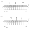
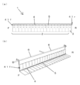
- FIGS. 1A and 1B are diagrams illustrating an installation structure of an internal air supply pipe 4 of a Necker flanger machine 1 according to an embodiment of the present invention, in which FIG. FIG. 10 is a diagram illustrating the installation structure of an internal air supply pipe 4 of a Necker flanger machine 1 which is a modified example of the present invention.
- 1A is a schematic diagram of a conventional necker flanger machine 1, in which (a) is a plan view, (b) is a perspective view, and (c) is a diagram showing the processing step of necking processing.
- 1A and 1B are schematic diagrams of necking processing, in which FIG. 1A shows the state before processing and FIG. 1A and 1B are diagrams for explaining the installation structure of an internal air supply pipe 4 of a conventional Necker flanger machine 1, in which (a) is a plan view and (b) is a perspective view.
- a Necker flanger machine 1 As an example of a can making device using air.
- the can making device using air is not limited to a Necker flanger machine, and may be a body maker, a trimmer, or the like. Also, it may be a Necker machine without a flanger.
- FIG. 1 is a diagram for explaining the installation structure of an internal air supply pipe 4 of a Necker flanger machine 1 according to an embodiment of the present invention, in which the machine main body of each unit is omitted and only the machine base 11 and the internal air supply pipe 4 are shown.
- the Necker flanger machine 1 of this embodiment is similar to the conventional Necker flanger machine 1 shown in FIG. 3 except for the piping structure of the internal air supply pipe 4.
- the unprocessed can body is carried into the front side (can entrance side) F of the necker flanger machine 1 and transported to the first necking processing unit 21.
- the first stage of processing is carried out in the first necking processing unit 21.
- the second stage of processing is carried out in the second necking processing unit 22, and then processing is carried out in each necking processing unit 2 (necking device) in sequence, and the final stage of processing is carried out in the last necking processing unit 2n.
- flanging is performed in the flanging unit 3.
- the results of the necking and flanging may be inspected by an inspection unit connected to the necker flanger machine 1 .
- the internal air supply pipe 4 has two internal air supply pipes 4 a and 4 b (air supply pipes) arranged along the longitudinal direction of the long Necker flanger machine 1 .
- the two internal air supply pipes 4a, 4b are arranged in each necking processing unit 2 so as to extend in parallel across the multiple necking processing units 2 from the front side F to the rear side R.
- the front side F ends (one end on the same side) of the two interior air supply pipes 4a, 4b are provided with air connection ports 41a, 41b through which air is supplied from the interior air supply pipe 6.
- the ends (other ends) on the rear side R of the two interior air supply pipes 4a, 4b are connected by a connecting pipe 42 to form a loop.
- the two interior air supply pipes 4a, 4b function as a single air supply pipe having air connection ports 41a, 41b at both ends.
- a branch air supply pipe 5 (branch pipe) for supplying air to each necking unit 2 is connected to each of the two internal air supply pipes 4 a, 4 b.
- the branch air supply pipe 5 is connected to the two internal air supply pipes 4a, 4b so that air is alternately supplied to each of the connected necking processing units 2.
- the branch air supply pipe 5 is connected to the internal air supply pipes 4a and 4b so that air is alternately supplied to every other necking processing unit 2, such that air is supplied from the internal air supply pipe 4a to the first necking processing unit 21 and from the internal air supply pipe 4b to the second necking processing unit 22, and thereafter, alternately, from the internal air supply pipe 4a to the odd-numbered necking processing units 2 and from the internal air supply pipe 4b to the even-numbered necking processing units 2.
- the air supplied to the internal air supply pipe 4 is discharged to the outside after being used in each necking unit 2. Therefore, the air in the internal air supply pipe 4 is constantly being consumed.
- the capacity of the internal air supply pipe 4 is larger and the air flow rate per internal air supply pipe is reduced compared to the conventional structure in which air is supplied from both ends of a single internal air supply pipe 4 as shown in Figure 5 (a) and air is supplied to all of the necking processing units 2 through a single internal air supply pipe 4, and therefore fluctuations in the air pressure and flow rate in the internal air supply pipe 4 can be reduced.
- the two internal air supply pipes 4a, 4b each supply air to half of all the necking processing units 2, the two internal air supply pipes 4a, 4b can be used evenly to supply air to each necking processing unit 2. That is, in this embodiment, the pressure and amount of air supplied to each necking processing unit 2 can be made more uniform.
- [Modification 1] 2(a) is a diagram for explaining the installation structure of the internal air supply pipe 4 of the Necker flanger machine 1 according to the first modified example of the present invention. Note that in this drawing, the flange processing unit 3 is omitted. In the above embodiment, every other branch air supply pipe 5 for supplying air to the plurality of connected necking processing units 2 is configured to be connected to two internal air supply pipes 4a, 4b, but this is not limiting, and as shown in Fig.
- the branch air supply pipe 5 for supplying air to half of the necking processing units 2 on the front side F of the plurality of connected necking processing units 2 may be connected to one internal air supply pipe 4a, and the branch air supply pipe 5 for supplying air to the remaining necking processing units 2 on the rear side R may be connected to the other internal air supply pipe 4b.
- air can be supplied evenly to each necking processing unit 2 using two internal air supply pipes 4a, 4b, and the pressure and amount of air supplied to each necking processing unit 2 can be made uniform.
- [Modification 2] 2B is a diagram for explaining the installation structure of the internal air supply pipe 4 of the Necker flanger machine 1 according to the second modified example of the present invention. Note that the flange processing unit 3 is omitted in this drawing.
- both of the two internal air supply pipes 4a, 4b are used to supply air to all of the necking processing units 2, but all of the branch air supply pipes 5 may be connected to only one internal air supply pipe 4a so that air is supplied from one internal air supply pipe 4a to all of the necking processing units 2.
- the branch air supply pipe 5 is connected to only one internal air supply pipe 4a, it is only necessary to provide a structure for connecting the branch air supply pipe 5 to only the internal air supply pipe 4a, and since the branch air supply pipe 5 is not connected to the other internal air supply pipe 4b, a simple pipe without a connection structure can be used. Furthermore, since the internal air supply pipe 4b does not supply air to the necking processing units 2, it is not necessary to place it in close proximity to the internal air supply pipe 4a, and the two internal air supply pipes 4a, 4b may be installed apart from each other, which increases the degree of freedom in the placement of the internal air supply pipes 4a, 4b.
- the internal air supply pipes 4a, 4b are each a single pipe extending from the front side F to the rear side R, but this is not limited thereto, and at least one of the internal air supply pipes 4a, 4b may be formed by connecting a plurality of pipes which are divided for each necking processing unit. That is, at least one of the internal air supply pipes 4 a, 4 b may be configured to have internal air supply split pipes connected thereto in the same number as the number of the necking units 2, each of which corresponds to one of the necking units 2.
- two types of in-house air intake division pipes are prepared: one unit of in-house air intake division pipe having a structure for connecting a branch air intake pipe 5, and one unit of in-house air intake division pipe not having a structure for connecting a branch air intake pipe 5, and these are connected alternately to form the in-house air intake pipes 4a, 4b.
- these two types of interior air supply division pipes may be connected in accordance with the arrangement of the branch air supply pipe 5 to form the interior air supply pipes 4a, 4b.
- the number of necking processing units 2 connected to the necker flanger machine 1 varies depending on the type of cans to be manufactured, and in the embodiment, variant 1, and variant 2, it is necessary to prepare internal air supply pipes 4a, 4b with a length that matches the number of connected necking processing units 2.
- variant 3 it is possible to configure internal air supply pipes 4a, 4b with a length that matches the number of connected necking processing units 2 simply by changing the number of internal air supply division pipes that are connected.
- the in-machine air intake division pipes are not limited to those corresponding to each necking processing unit 2, but may be prepared to correspond to a plurality of necking processing units 2.
- Such in-machine air intake division pipes corresponding to a plurality of necking processing units 2 can reduce the number of steps required for connecting the in-machine air intake division pipes, and also contribute to reducing the possibility of air leakage from the connection between the two in-machine air intake division pipes and reducing the maintenance work required for the connection.
- interior air intake split pipes there may be mentioned two units of interior air intake split pipes, each having one portion having a structure for connecting the branch air intake pipe 5 and one portion not having a structure for connecting the branch air intake pipe 5, two units of interior air intake split pipes, each having two portions having a structure for connecting the branch air intake pipe 5, and two units of interior air intake split pipes, each having two portions not having a structure for connecting the branch air intake pipe 5.
- Interior air intake split pipes are not limited to two units as above, and interior air intake split pipes for three or more units may be prepared, but preparing too many types of interior air intake split pipes is disadvantageous in terms of costs, so it is preferable to prepare the air intake split pipes taking various circumstances into consideration.
- Necker flanger machine 11 Machine base 2 Necking processing unit 3 Flange processing unit 4, 4a, 4b In-machine air supply pipe 41a, 41b Air connection port 41f Front side air connection port 41r Rear side air connection port 42 Connection pipe 5 Branch air supply pipe 6 In-building air supply pipe C Can body BC Bottom chuck CL Centering IS Insert F Front side R Rear side
Landscapes
- Engineering & Computer Science (AREA)
- Mechanical Engineering (AREA)
- Pipeline Systems (AREA)
Abstract
プラントへの圧縮エアを供給する配管を簡素化できる給気管構造を有する製缶装置を提供することを課題とする。 加工ユニットが連結された製缶装置であって、複数の前記加工ユニットにわたって並行して伸びる2本の給気管を有し、2本の前記給気管の同じ側の一端にエアが供給され、2本の前記給気管の他端はつながれていて、2本の前記給気管はループを構成しており、前記給気管の少なくとも1本は、前記給気管から前記加工ユニットにそれぞれエアを供給する分岐管を有することを特徴とする製缶装置。
Description
本発明は、製缶装置、特に、エアを使用する製缶装置に関する。
従来から、製缶工程の缶胴の成形工程では、プレス機を用いた絞り加工及び/又は絞りしごき加工、缶の開口部のエッジ部をトリマーによるトリミング加工等の後、開口部を徐々に縮径する形状に成形する絞り加工(ネッキング加工)と缶蓋を巻き締めるためのフランジを形成するフランジ加工が行われる。(特許文献1)
このネッキング加工とフランジ加工は、ネッカーフランジャーマシン1により行われる。ネッキング加工は複数回の加工により所望の形状に成形するため、ネッカーフランジャーマシン1は、複数のネッキング加工ユニット2、フランジ加工ユニット3等が連結された長尺のプラントとなる。(図3(a)、(b)参照)
そして、複数のネッキング加工ユニット2により、缶胴の開口部に徐々に絞り加工を施してネック部の形状を形成していく。(図3(c)参照)
このネッキング加工とフランジ加工は、ネッカーフランジャーマシン1により行われる。ネッキング加工は複数回の加工により所望の形状に成形するため、ネッカーフランジャーマシン1は、複数のネッキング加工ユニット2、フランジ加工ユニット3等が連結された長尺のプラントとなる。(図3(a)、(b)参照)
そして、複数のネッキング加工ユニット2により、缶胴の開口部に徐々に絞り加工を施してネック部の形状を形成していく。(図3(c)参照)
ネッキング加工では、ネッキング成形時に、缶胴Cのトリム側(開口側)のカムとボトム側のカムにより、メインターレットの回転に伴って、ネッキングツール(インサートISとセンタリングCL)がスライドし、ボトムチャックBCにより缶胴Cのボトムを吸着しながらネッキング加工を施す。このネッキング加工時に、圧縮エアを缶胴内に吹き込むことにより、缶胴内を加圧し座屈や変形を防止している。(図4参照)
図5に示すように、各ネッキング加工ユニット2に圧縮エアを供給する配管(給気管)として、プラントのフロント側(缶の搬入側)Fからリア側(缶の搬出側)Rまで、1本の機内給気管4を設置して、この機内給気管4から各ネッキング加工ユニット2に圧縮エアを供給する分岐給気管5を接続した構造になっている。そして、長尺のプラントに複数連結される各ネッキング加工ユニット2に均等に圧縮エアを供給するために、1本の機内給気管4のフロント側Fとリア側Rの2か所に、それぞれ、圧縮エアを供給するフロント側エア接続口41fとリア側エア接続口41rを設けて、プラント外から圧縮エアを供給する構造になっている。
また、フロント側エア接続口41fとリア側エア接続口41rのそれぞれには、プラントを収容する建屋に設置された建屋内給気管6から圧縮エアが供給される。
この配管構造では、長尺のプラントの両端に、エア接続口が設けられているために、建屋内には、これら離れた位置にある2か所のエア接続口に圧縮エアを供給する建屋内給気管6を取りまわして設置する必要があり、建屋内給気管6の設置やメンテナンスにコストがかかるという問題があった。
また、フロント側エア接続口41fとリア側エア接続口41rのそれぞれには、プラントを収容する建屋に設置された建屋内給気管6から圧縮エアが供給される。
この配管構造では、長尺のプラントの両端に、エア接続口が設けられているために、建屋内には、これら離れた位置にある2か所のエア接続口に圧縮エアを供給する建屋内給気管6を取りまわして設置する必要があり、建屋内給気管6の設置やメンテナンスにコストがかかるという問題があった。
本発明は、プラントへの圧縮エアを供給する配管を簡素化できる給気管構造を有する製缶装置を提供することを課題とする。
前記課題を解決するために、本発明の製缶装置は、以下の構成を具備するものである。
加工ユニットが連結された製缶装置であって、
複数の前記加工ユニットにわたって並行して伸びる2本の給気管を有し、
2本の前記給気管の同じ側の一端にエアが供給され、
2本の前記給気管の他端はつながれていて、2本の前記給気管はループを構成しており、
前記給気管の少なくとも1本は、前記給気管から前記加工ユニットにそれぞれエアを供給する分岐管を有する
ことを特徴とする製缶装置。
加工ユニットが連結された製缶装置であって、
複数の前記加工ユニットにわたって並行して伸びる2本の給気管を有し、
2本の前記給気管の同じ側の一端にエアが供給され、
2本の前記給気管の他端はつながれていて、2本の前記給気管はループを構成しており、
前記給気管の少なくとも1本は、前記給気管から前記加工ユニットにそれぞれエアを供給する分岐管を有する
ことを特徴とする製缶装置。
本発明は、ループを構成する2本の給気管を設置することにより、2つのエア接続口を近接して配置することができ、プラントを収容する建屋内に配管構造を簡素化することができる。
以下、図面を参照して本発明の実施形態を説明する。以下の説明で、異なる図における同一符号は同一機能の部位を示しており、各図における重複説明は適宜省略する。
[実施形態]
以下、エアを用いた製缶装置として、ネッカーフランジャーマシン1を例に挙げて、説明する。なお、エアを用いた製缶装置は、ネッカーフランジャーマシンに限らず、ボディメーカー、トリマー等でもよい。また、フランジャーを有しない、ネッカーマシンであってもよい。
以下、エアを用いた製缶装置として、ネッカーフランジャーマシン1を例に挙げて、説明する。なお、エアを用いた製缶装置は、ネッカーフランジャーマシンに限らず、ボディメーカー、トリマー等でもよい。また、フランジャーを有しない、ネッカーマシンであってもよい。
[全体構成]
図1は、本発明の実施形態であるネッカーフランジャーマシン1の機内給気管4の設置構造を説明する図であり、各ユニットのマシン本体を省略して、マシンベース11と機内給気管4のみを示している。
本実施形態のネッカーフランジャーマシン1は、機内給気管4の配管構造を除いて、図3に示される従来のネッカーフランジャーマシン1と同様のものである。
ネッカーフランジャーマシン1のフロント側(缶の搬入側)Fには、加工前の缶胴が搬入され、1番目のネッキング加工ユニット21に搬送される。
一番目のネッキング加工ユニット21で第1段階の加工が行われる。その後、2番目のネッキング加工ユニット22で第2段階の加工が行われ、その後、順次、各ネッキング加工ユニット2(ネッキング装置)で加工が行われ、最後のネッキング加工ユニット2nで最終段階の加工が行われる。
ネッキング加工が終了すると、フランジ加工ユニット3でフランジ加工が行われる。
フランジ加工終了後、ネッカーフランジャーマシン1に連結された検査ユニットにより、ネッキング加工、フランジ加工の結果を検査するようにしてもよい。
すべての工程が終了すると、リア側(缶の搬出側)Rから加工された缶胴が搬出される。
図1は、本発明の実施形態であるネッカーフランジャーマシン1の機内給気管4の設置構造を説明する図であり、各ユニットのマシン本体を省略して、マシンベース11と機内給気管4のみを示している。
本実施形態のネッカーフランジャーマシン1は、機内給気管4の配管構造を除いて、図3に示される従来のネッカーフランジャーマシン1と同様のものである。
ネッカーフランジャーマシン1のフロント側(缶の搬入側)Fには、加工前の缶胴が搬入され、1番目のネッキング加工ユニット21に搬送される。
一番目のネッキング加工ユニット21で第1段階の加工が行われる。その後、2番目のネッキング加工ユニット22で第2段階の加工が行われ、その後、順次、各ネッキング加工ユニット2(ネッキング装置)で加工が行われ、最後のネッキング加工ユニット2nで最終段階の加工が行われる。
ネッキング加工が終了すると、フランジ加工ユニット3でフランジ加工が行われる。
フランジ加工終了後、ネッカーフランジャーマシン1に連結された検査ユニットにより、ネッキング加工、フランジ加工の結果を検査するようにしてもよい。
すべての工程が終了すると、リア側(缶の搬出側)Rから加工された缶胴が搬出される。
[機内給気管]
図1に示すように、機内給気管4は、長尺のネッカーフランジャーマシン1の長手方向に沿うように配管された2本の機内給気管4a、4b(給気管)を有する。
2本の機内給気管4a、4bは、フロント側Fからリア側Rまで、複数のネッキング加工ユニット2にわたって並行して伸びるように、各ネッキング加工ユニット2内に配置されている。
2本の機内給気管4a、4bのフロント側Fの端部(同じ側の一端)は、建屋内給気管6からエアの供給を受けるエア接続口41a、41bが設けられている。
また、2本の機内給気管4a、4bのリア側Rの端部(他端)は、接続管42により接続されていて、ループを形成している。
この構成により、2本の機内給気管4a、4bは、両端に、エア接続口41a、41bを有する1本の給気管として機能する。
図1に示すように、機内給気管4は、長尺のネッカーフランジャーマシン1の長手方向に沿うように配管された2本の機内給気管4a、4b(給気管)を有する。
2本の機内給気管4a、4bは、フロント側Fからリア側Rまで、複数のネッキング加工ユニット2にわたって並行して伸びるように、各ネッキング加工ユニット2内に配置されている。
2本の機内給気管4a、4bのフロント側Fの端部(同じ側の一端)は、建屋内給気管6からエアの供給を受けるエア接続口41a、41bが設けられている。
また、2本の機内給気管4a、4bのリア側Rの端部(他端)は、接続管42により接続されていて、ループを形成している。
この構成により、2本の機内給気管4a、4bは、両端に、エア接続口41a、41bを有する1本の給気管として機能する。
2本の機内給気管4a、4bには、それぞれ、各ネッキング加工ユニット2にエアを供給するための分岐給気管5(分岐管)が接続されている。
本実施形態では、2本の機内給気管4a、4bが、連結された各ネッキング加工ユニット2に交互にエアを供給するように、分岐給気管5が接続されている。すなわち、一番目のネッキング加工ユニット21には機内給気管4aから、2番目のネッキング加工ユニット22には機内給気管4bから、以降、交互に、奇数番目のネッキング加工ユニット2には機内給気管4aから、偶数番目のネッキング加工ユニット2には機内給気管4bから、エアが供給されるように、機内給気管4a、機内給気管4bには、1つおきのネッキング加工ユニット2にエアが供給されるように、分岐給気管5が接続されている。
本実施形態では、2本の機内給気管4a、4bが、連結された各ネッキング加工ユニット2に交互にエアを供給するように、分岐給気管5が接続されている。すなわち、一番目のネッキング加工ユニット21には機内給気管4aから、2番目のネッキング加工ユニット22には機内給気管4bから、以降、交互に、奇数番目のネッキング加工ユニット2には機内給気管4aから、偶数番目のネッキング加工ユニット2には機内給気管4bから、エアが供給されるように、機内給気管4a、機内給気管4bには、1つおきのネッキング加工ユニット2にエアが供給されるように、分岐給気管5が接続されている。
機内給気管4に供給されたエアは、各ネッキング加工ユニット2で使用されると、外部へと排出される。このため、機内給気管4内のエアは常に消費され続ける。
2本の機内給気管4a、4bによりすべてのネッキング加工ユニット2にエアを供給する本実施形態は、図5(a)に示される1本の機内給気管4の両端からエアを供給し、1本の機内給気管4によりすべてのネッキング加工ユニット2にエアを供給する従来の構造に比べて、機内給気管4内の容量が多く、また、機内給気管1本あたりのエア流量が減るため、機内給気管4内のエアの圧力や流量の変動を小さくすることができる。
また、2本の機内給気管4a、4bが、それぞれ、すべてのネッキング加工ユニット2の半数にエアを供給するため、2本の機内給気管4a、4bを均等に使用して各ネッキング加工ユニット2にエアを供給することができる。
すなわち、本実施形態では、各ネッキング加工ユニット2に供給されるエアの圧力や量などをより均一にすることができる。
2本の機内給気管4a、4bによりすべてのネッキング加工ユニット2にエアを供給する本実施形態は、図5(a)に示される1本の機内給気管4の両端からエアを供給し、1本の機内給気管4によりすべてのネッキング加工ユニット2にエアを供給する従来の構造に比べて、機内給気管4内の容量が多く、また、機内給気管1本あたりのエア流量が減るため、機内給気管4内のエアの圧力や流量の変動を小さくすることができる。
また、2本の機内給気管4a、4bが、それぞれ、すべてのネッキング加工ユニット2の半数にエアを供給するため、2本の機内給気管4a、4bを均等に使用して各ネッキング加工ユニット2にエアを供給することができる。
すなわち、本実施形態では、各ネッキング加工ユニット2に供給されるエアの圧力や量などをより均一にすることができる。
[変形例1]
図2(a)は、本発明の変形例1であるネッカーフランジャーマシン1の機内給気管4の設置構造を説明する図である。なお、この図では、フランジ加工ユニット3は省略している。
上述の実施形態では、連結された複数のネッキング加工ユニット2にエアを供給する分岐給気管5を1つおきに、2本の機内給気管4a、4bに接続するよう構成したが、これに限らず、図2(a)に示すように、連結された複数のネッキング加工ユニット2のフロント側Fの半数のネッキング加工ユニット2にエアを供給する分岐給気管5を1本の機内給気管4aに、リア側Rの残りのネッキング加工ユニット2にエアを供給する分岐給気管5をもう1本の機内給気管4bに接続してもよい。この変形例1においても、上述の実施形態と同様、2本の機内給気管4a、4bを使用して、均等に各ネッキング加工ユニット2にエアを供給することができ、各ネッキング加工ユニット2に供給されるエアの圧力や量などを均一にすることができる。
図2(a)は、本発明の変形例1であるネッカーフランジャーマシン1の機内給気管4の設置構造を説明する図である。なお、この図では、フランジ加工ユニット3は省略している。
上述の実施形態では、連結された複数のネッキング加工ユニット2にエアを供給する分岐給気管5を1つおきに、2本の機内給気管4a、4bに接続するよう構成したが、これに限らず、図2(a)に示すように、連結された複数のネッキング加工ユニット2のフロント側Fの半数のネッキング加工ユニット2にエアを供給する分岐給気管5を1本の機内給気管4aに、リア側Rの残りのネッキング加工ユニット2にエアを供給する分岐給気管5をもう1本の機内給気管4bに接続してもよい。この変形例1においても、上述の実施形態と同様、2本の機内給気管4a、4bを使用して、均等に各ネッキング加工ユニット2にエアを供給することができ、各ネッキング加工ユニット2に供給されるエアの圧力や量などを均一にすることができる。
[変形例2]
図2(b)は、本発明の変形例2であるネッカーフランジャーマシン1の機内給気管4の設置構造を説明する図である。なお、この図では、フランジ加工ユニット3は省略している。
上述の実施形態及び変形例1では、2本の機内給気管4a、4bの両方を使用してすべてのネッキング加工ユニット2にエアを供給しているが、1本の機内給気管4aからすべてのネッキング加工ユニット2にエアを供給するように、すべての分岐給気管5を1本の機内給気管4aのみに接続してもよい。この変形例では、1本の機内給気管4aのみに分岐給気管5を接続するので、機内給気管4aのみに分岐給気管5を接続する構造を設ければよく、もう1本の機内給気管4bは、分岐給気管5が接続されないので、接続構造のない簡単な管を使用することができる。また、機内給気管4bは、ネッキング加工ユニット2にエアを供給するものではないため、機内給気管4aに近接した位置に配置する必要はなく、2本の機内給気管4a、4bは離間して設置してもよく、機内給気管4a、4bの配置の自由度が高くなる。
図2(b)は、本発明の変形例2であるネッカーフランジャーマシン1の機内給気管4の設置構造を説明する図である。なお、この図では、フランジ加工ユニット3は省略している。
上述の実施形態及び変形例1では、2本の機内給気管4a、4bの両方を使用してすべてのネッキング加工ユニット2にエアを供給しているが、1本の機内給気管4aからすべてのネッキング加工ユニット2にエアを供給するように、すべての分岐給気管5を1本の機内給気管4aのみに接続してもよい。この変形例では、1本の機内給気管4aのみに分岐給気管5を接続するので、機内給気管4aのみに分岐給気管5を接続する構造を設ければよく、もう1本の機内給気管4bは、分岐給気管5が接続されないので、接続構造のない簡単な管を使用することができる。また、機内給気管4bは、ネッキング加工ユニット2にエアを供給するものではないため、機内給気管4aに近接した位置に配置する必要はなく、2本の機内給気管4a、4bは離間して設置してもよく、機内給気管4a、4bの配置の自由度が高くなる。
[変形例3]
上述の実施形態、変形例1及び変形例2では、機内給気管4a、4bは、フロント側Fからリア側Rまでを、それぞれ、1本の管としたものであるが、これに限らず、機内給気管4a、4bの少なくとも1つは、各ネッキング加工ユニット毎に分割された複数の管を接続したものとしてもよい。
すなわち、機内給気管4a、4bの少なくとも1つは、各ネッキング加工ユニット2に対応する機内給気分割管を、ネッキング加工ユニット2の数だけ接続したものとしてもよい。
例えば、上述の実施形態では、分岐給気管5を接続する構造を有する1ユニット分の機内給気分割管と、分岐給気管5を接続する構造を有さない1ユニット分の機内給気分割管の2種類を準備して、これらを交互に接続して、機内給気管4a、4bを構成すればよい。
また、上述の変形例1及び変形例2でも、これら2種類の機内給気分割管を、分岐給気管5の配置に合わせて接続して、機内給気管4a、4bを構成すればよい。
上述の実施形態、変形例1及び変形例2では、機内給気管4a、4bは、フロント側Fからリア側Rまでを、それぞれ、1本の管としたものであるが、これに限らず、機内給気管4a、4bの少なくとも1つは、各ネッキング加工ユニット毎に分割された複数の管を接続したものとしてもよい。
すなわち、機内給気管4a、4bの少なくとも1つは、各ネッキング加工ユニット2に対応する機内給気分割管を、ネッキング加工ユニット2の数だけ接続したものとしてもよい。
例えば、上述の実施形態では、分岐給気管5を接続する構造を有する1ユニット分の機内給気分割管と、分岐給気管5を接続する構造を有さない1ユニット分の機内給気分割管の2種類を準備して、これらを交互に接続して、機内給気管4a、4bを構成すればよい。
また、上述の変形例1及び変形例2でも、これら2種類の機内給気分割管を、分岐給気管5の配置に合わせて接続して、機内給気管4a、4bを構成すればよい。
ネッカーフランジャーマシン1は、製造する缶の種類などに応じて、連結されるネッキング加工ユニット2の数が異なるものであり、実施形態、変形例1及び変形例2では、連結されたネッキング加工ユニット2の数に合わせた長さの機内給気管4a、4bを準備する必要がある。しかし、変形例3では、連結する機内給気分割管の数を変えるだけで、連結されたネッキング加工ユニット2の数に合わせた長さの機内給気管4a、4bを構成することができる。
さらに、機内給気分割管は、各ネッキング加工ユニット2に対応するものに限らず、複数のネッキング加工ユニット2に対応するものを準備してもよい。このような複数のネッキング加工ユニット2に対応する機内給気分割管は、機内給気分割管の接続作業の工数が減少できるとともに、2つの機内給気分割管の間の接続部分からのエア漏れなどが起きる可能性の減少、該接続部分のメンテナンス作業の減少にも寄与する。
例えば、分岐給気管5を接続する構造を有する部分と分岐給気管5を接続する構造を有さない部分を1つずつ有する、2ユニット分の機内給気分割管、分岐給気管5を接続する構造を有する部分を2つずつ有する2ユニット分の機内給気分割管、分岐給気管5を接続する構造を有さない部分を2つずつ有する2ユニット分の機内給気分割管などが挙げられる。これらのような2ユニット分の機内給気分割管に限らず、3ユニット分以上の機内給気分割管を準備してもよいが、あまり多くの種類の機内給気分割管を準備することは、コストの面で不利になるので、種々の事情を考慮して、給気分割管を準備することが好ましい。
例えば、分岐給気管5を接続する構造を有する部分と分岐給気管5を接続する構造を有さない部分を1つずつ有する、2ユニット分の機内給気分割管、分岐給気管5を接続する構造を有する部分を2つずつ有する2ユニット分の機内給気分割管、分岐給気管5を接続する構造を有さない部分を2つずつ有する2ユニット分の機内給気分割管などが挙げられる。これらのような2ユニット分の機内給気分割管に限らず、3ユニット分以上の機内給気分割管を準備してもよいが、あまり多くの種類の機内給気分割管を準備することは、コストの面で不利になるので、種々の事情を考慮して、給気分割管を準備することが好ましい。
[建屋内給気管]
図1(b)に示すように、建屋内給気管6は、ネッカーフランジャーマシン1のフロント側Fに配置された1本の給気管のみが設置される。この1本の建屋内給気管6に、並んで配置される2つのエア接続口41a、41bを接続するだけで、機内給気管4a、4bにエアを供給することができる。
図5(b)に示される従来の建屋内給気管6に比べれば、配管が簡単なことは明らかである。
図1(b)に示すように、建屋内給気管6は、ネッカーフランジャーマシン1のフロント側Fに配置された1本の給気管のみが設置される。この1本の建屋内給気管6に、並んで配置される2つのエア接続口41a、41bを接続するだけで、機内給気管4a、4bにエアを供給することができる。
図5(b)に示される従来の建屋内給気管6に比べれば、配管が簡単なことは明らかである。
以上、本発明に係る実施形態、変形例1、変形例2及び変形例3を、図面を参照して詳述してきたが、具体的な構成は、これらの実施の形態に限られるものではなく、本発明の要旨を逸脱しない範囲の設計の変更等があっても本発明に含まれる。
また、前述の実施形態及び各変形例は、その目的および構成等に特に矛盾や問題がない限り、互いの技術を流用して組み合わせることが可能である。
また、前述の実施形態及び各変形例は、その目的および構成等に特に矛盾や問題がない限り、互いの技術を流用して組み合わせることが可能である。
1 ネッカーフランジャーマシン
11 マシンベース
2 ネッキング加工ユニット
3 フランジ加工ユニット
4、4a、4b 機内給気管
41a、41b エア接続口
41f フロント側エア接続口
41r リア側エア接続口
42 接続管
5 分岐給気管
6 建屋内給気管
C 缶胴
BC ボトムチャック
CL センタリング
IS インサート
F フロント側
R リア側
11 マシンベース
2 ネッキング加工ユニット
3 フランジ加工ユニット
4、4a、4b 機内給気管
41a、41b エア接続口
41f フロント側エア接続口
41r リア側エア接続口
42 接続管
5 分岐給気管
6 建屋内給気管
C 缶胴
BC ボトムチャック
CL センタリング
IS インサート
F フロント側
R リア側
Claims (7)
- 加工ユニットが連結された製缶装置であって、
複数の前記加工ユニットにわたって並行して伸びる2本の給気管を有し、
2本の前記給気管の同じ側の一端にエアが供給され、
2本の前記給気管の他端はつながれていて、2本の前記給気管はループを構成しており、
前記給気管の少なくとも1本は、前記給気管から前記加工ユニットにそれぞれエアを供給する分岐管を有する
ことを特徴とする製缶装置。 - 2本の前記給気管が前記分岐管を有することを特徴とする請求項1に記載された製缶装置。
- 2本の前記給気管は、それぞれ、1つおきの前記加工ユニットにエアを供給する前記分岐管を有し、
2本の前記給気管の前記分岐管により、前記加工ユニットに交互にエアを供給することを特徴とする請求項1に記載された製缶装置。 - 1本の前記給気管のみが前記分岐管を有することを特徴とする請求項1に記載された製缶装置。
- 前記給気管は前記加工ユニット内に配置されていることを特徴とする請求項1に記載された製缶装置。
- 前記給気管は前記加工ユニット毎に分割されていることを特徴とする請求項1に記載された製缶装置。
- 前記加工ユニットはネッキング装置であることを特徴とする請求項1~6の何れか1項に記載された製缶装置。
Applications Claiming Priority (2)
| Application Number | Priority Date | Filing Date | Title |
|---|---|---|---|
| JP2023108178A JP7567997B1 (ja) | 2023-06-30 | 2023-06-30 | 製缶装置 |
| JP2023-108178 | 2023-06-30 |
Publications (1)
| Publication Number | Publication Date |
|---|---|
| WO2025004489A1 true WO2025004489A1 (ja) | 2025-01-02 |
Family
ID=93058001
Family Applications (1)
| Application Number | Title | Priority Date | Filing Date |
|---|---|---|---|
| PCT/JP2024/014004 Ceased WO2025004489A1 (ja) | 2023-06-30 | 2024-04-05 | 製缶装置 |
Country Status (2)
| Country | Link |
|---|---|
| JP (1) | JP7567997B1 (ja) |
| WO (1) | WO2025004489A1 (ja) |
Citations (4)
| Publication number | Priority date | Publication date | Assignee | Title |
|---|---|---|---|---|
| JPS508199U (ja) * | 1973-05-24 | 1975-01-28 | ||
| JP2961526B2 (ja) * | 1996-10-31 | 1999-10-12 | 日本エアーカーテン株式会社 | 集塵装置 |
| JP2000334411A (ja) * | 1999-05-26 | 2000-12-05 | Ishikawajima Harima Heavy Ind Co Ltd | コンベヤ乗り継ぎ部における粉塵の拡散防止及び回収装置 |
| JP2018012140A (ja) * | 2016-07-11 | 2018-01-25 | ユニバーサル製缶株式会社 | 缶成形装置 |
-
2023
- 2023-06-30 JP JP2023108178A patent/JP7567997B1/ja active Active
-
2024
- 2024-04-05 WO PCT/JP2024/014004 patent/WO2025004489A1/ja not_active Ceased
Patent Citations (4)
| Publication number | Priority date | Publication date | Assignee | Title |
|---|---|---|---|---|
| JPS508199U (ja) * | 1973-05-24 | 1975-01-28 | ||
| JP2961526B2 (ja) * | 1996-10-31 | 1999-10-12 | 日本エアーカーテン株式会社 | 集塵装置 |
| JP2000334411A (ja) * | 1999-05-26 | 2000-12-05 | Ishikawajima Harima Heavy Ind Co Ltd | コンベヤ乗り継ぎ部における粉塵の拡散防止及び回収装置 |
| JP2018012140A (ja) * | 2016-07-11 | 2018-01-25 | ユニバーサル製缶株式会社 | 缶成形装置 |
Also Published As
| Publication number | Publication date |
|---|---|
| JP2025007041A (ja) | 2025-01-17 |
| JP7567997B1 (ja) | 2024-10-16 |
Similar Documents
| Publication | Publication Date | Title |
|---|---|---|
| EP0767713B1 (en) | Modular base can processing equipment | |
| US20120292159A1 (en) | Adjustable transfer assembly for container manufacturing process | |
| EP2401216B1 (en) | Quick change for transfer starwheel | |
| TWI912246B (zh) | 四站式製程模組的前級總成 | |
| JP7567997B1 (ja) | 製缶装置 | |
| CN110202603B (zh) | 一种真空吸盘以及吸盘本体的制造方法 | |
| US3029667A (en) | Metal working | |
| CN115302209A (zh) | 通过内外壁一体成形方案制造火箭发动机喷管的方法 | |
| CN117754914A (zh) | 一种高速伺服纸杯机 | |
| CN105501506B (zh) | 一种中灯自动包装机 | |
| CN115605318A (zh) | 用于工件特别是车身零件的生产站以及生产系统 | |
| CN111002072A (zh) | 转盘式加工平台系统 | |
| EP2799373B1 (en) | Press system with vacuum port assembly | |
| JPS62501024A (ja) | 無限軌道車用のギア装置 | |
| CN1498788A (zh) | 用于车辆的冷凝器 | |
| WO2023195934A1 (en) | Machine tool reinforced vacuum line | |
| CN117047417A (zh) | 一种管式冷油器制造方法 | |
| CN210462085U (zh) | 充气接头组件 | |
| US11759899B2 (en) | Tooling plate for conveying different work parts in an assembly line, and method for configuring the same | |
| CN211029108U (zh) | 一种供气装置 | |
| CN105480460B (zh) | 一种中灯自动包装机的灯泡装卡纸定位装置 | |
| GB2302914A (en) | Mounting exhaust-driven turbochargers on a support housing | |
| JPH08126916A (ja) | 熱交換器用液圧拡管装置およびシステム | |
| CN224186452U (zh) | 一种多工位真空定型快速蒸箱 | |
| CN117644590B (zh) | 一种多晶硅还原炉用石墨卡座的加工方法 |
Legal Events
| Date | Code | Title | Description |
|---|---|---|---|
| 121 | Ep: the epo has been informed by wipo that ep was designated in this application |
Ref document number: 24831364 Country of ref document: EP Kind code of ref document: A1 |
|
| NENP | Non-entry into the national phase |
Ref country code: DE |