WO2025004476A1 - ボイラ、ボイラの改造方法及びボイラの運転方法 - Google Patents
ボイラ、ボイラの改造方法及びボイラの運転方法 Download PDFInfo
- Publication number
- WO2025004476A1 WO2025004476A1 PCT/JP2024/011628 JP2024011628W WO2025004476A1 WO 2025004476 A1 WO2025004476 A1 WO 2025004476A1 JP 2024011628 W JP2024011628 W JP 2024011628W WO 2025004476 A1 WO2025004476 A1 WO 2025004476A1
- Authority
- WO
- WIPO (PCT)
- Prior art keywords
- ammonia
- burner
- supply amount
- furnace
- boiler
- Prior art date
- Legal status (The legal status is an assumption and is not a legal conclusion. Google has not performed a legal analysis and makes no representation as to the accuracy of the status listed.)
- Ceased
Links
Images



Classifications
-
- F—MECHANICAL ENGINEERING; LIGHTING; HEATING; WEAPONS; BLASTING
- F23—COMBUSTION APPARATUS; COMBUSTION PROCESSES
- F23C—METHODS OR APPARATUS FOR COMBUSTION USING FLUID FUEL OR SOLID FUEL SUSPENDED IN A CARRIER GAS OR AIR
- F23C1/00—Combustion apparatus specially adapted for combustion of two or more kinds of fuel simultaneously or alternately, at least one kind of fuel being either a fluid fuel or a solid fuel suspended in a carrier gas or air
- F23C1/08—Combustion apparatus specially adapted for combustion of two or more kinds of fuel simultaneously or alternately, at least one kind of fuel being either a fluid fuel or a solid fuel suspended in a carrier gas or air liquid and gaseous fuel
-
- F—MECHANICAL ENGINEERING; LIGHTING; HEATING; WEAPONS; BLASTING
- F23—COMBUSTION APPARATUS; COMBUSTION PROCESSES
- F23C—METHODS OR APPARATUS FOR COMBUSTION USING FLUID FUEL OR SOLID FUEL SUSPENDED IN A CARRIER GAS OR AIR
- F23C1/00—Combustion apparatus specially adapted for combustion of two or more kinds of fuel simultaneously or alternately, at least one kind of fuel being either a fluid fuel or a solid fuel suspended in a carrier gas or air
- F23C1/10—Combustion apparatus specially adapted for combustion of two or more kinds of fuel simultaneously or alternately, at least one kind of fuel being either a fluid fuel or a solid fuel suspended in a carrier gas or air liquid and pulverulent fuel
-
- F—MECHANICAL ENGINEERING; LIGHTING; HEATING; WEAPONS; BLASTING
- F23—COMBUSTION APPARATUS; COMBUSTION PROCESSES
- F23C—METHODS OR APPARATUS FOR COMBUSTION USING FLUID FUEL OR SOLID FUEL SUSPENDED IN A CARRIER GAS OR AIR
- F23C1/00—Combustion apparatus specially adapted for combustion of two or more kinds of fuel simultaneously or alternately, at least one kind of fuel being either a fluid fuel or a solid fuel suspended in a carrier gas or air
- F23C1/12—Combustion apparatus specially adapted for combustion of two or more kinds of fuel simultaneously or alternately, at least one kind of fuel being either a fluid fuel or a solid fuel suspended in a carrier gas or air gaseous and pulverulent fuel
-
- F—MECHANICAL ENGINEERING; LIGHTING; HEATING; WEAPONS; BLASTING
- F23—COMBUSTION APPARATUS; COMBUSTION PROCESSES
- F23D—BURNERS
- F23D1/00—Burners for combustion of pulverulent fuel
-
- F—MECHANICAL ENGINEERING; LIGHTING; HEATING; WEAPONS; BLASTING
- F23—COMBUSTION APPARATUS; COMBUSTION PROCESSES
- F23D—BURNERS
- F23D14/00—Burners for combustion of a gas, e.g. of a gas stored under pressure as a liquid
- F23D14/02—Premix gas burners, i.e. in which gaseous fuel is mixed with combustion air upstream of the combustion zone
-
- F—MECHANICAL ENGINEERING; LIGHTING; HEATING; WEAPONS; BLASTING
- F23—COMBUSTION APPARATUS; COMBUSTION PROCESSES
- F23D—BURNERS
- F23D17/00—Burners for combustion simultaneously or alternately of gaseous or liquid or pulverulent fuel
-
- F—MECHANICAL ENGINEERING; LIGHTING; HEATING; WEAPONS; BLASTING
- F23—COMBUSTION APPARATUS; COMBUSTION PROCESSES
- F23J—REMOVAL OR TREATMENT OF COMBUSTION PRODUCTS OR COMBUSTION RESIDUES; FLUES
- F23J7/00—Arrangement of devices for supplying chemicals to fire
-
- F—MECHANICAL ENGINEERING; LIGHTING; HEATING; WEAPONS; BLASTING
- F23—COMBUSTION APPARATUS; COMBUSTION PROCESSES
- F23N—REGULATING OR CONTROLLING COMBUSTION
- F23N1/00—Regulating fuel supply
Definitions
- the present disclosure relates to a boiler, a method for retrofitting a boiler, and a method for operating a boiler.
- Boilers equipped with burners that burn ammonia as fuel are known.
- Patent Document 1 describes a boiler equipped with a burner that burns ammonia and pulverized coal.
- ammonia has a slower burning speed than common hydrocarbon fuels such as methane, making it difficult to ignite and burn.
- liquid ammonia has a large heat of vaporization, which is thought to reduce its ignition ability. Therefore, it is desirable to be able to ensure both the amount of ammonia supply and ignition stability in boilers that use ammonia as fuel.
- At least one embodiment of the present invention aims to provide a boiler, a method for modifying a boiler, and a method for operating a boiler that can ensure both an adequate ammonia supply and ignition stability.
- At least one embodiment of the boiler of the present invention comprises: a furnace for burning fuel; an ammonia diffusion burner configured to inject liquid ammonia into the furnace; an ammonia premix burner configured to inject a premix of gaseous ammonia and air into the furnace; Equipped with.
- a method for retrofitting a boiler includes the steps of: A method for retrofitting a boiler including a furnace, an oil burner for injecting oil into the furnace, and a pulverized fuel burner for injecting pulverized fuel together with air into the furnace, comprising: converting the oil burner into an ammonia diffusion burner for injecting liquid ammonia into the furnace; converting the pulverized fuel burner into an ammonia premix burner for injecting a premix of gaseous ammonia and air into the furnace; Equipped with.
- a method for retrofitting a boiler includes the steps of: A method for retrofitting a boiler including a furnace, an oil burner for injecting oil into the furnace, and a pulverized fuel burner for injecting pulverized fuel together with air into the furnace, comprising: converting the oil burner into an ammonia premix burner for injecting a premix of gaseous ammonia and air into the furnace; converting the pulverized fuel burner into an ammonia diffusion burner for injecting liquid ammonia into the furnace; Equipped with.
- a method for operating a boiler includes the steps of: A method for operating the boiler described above, comprising: The method includes a step of adjusting a diffusion ammonia supply amount, which is an ammonia supply amount to the furnace via the ammonia diffusion burner, and a premixed ammonia supply amount, which is an ammonia supply amount to the furnace via the ammonia premixing burner, based on a required load of the boiler; In the step, when the load of the boiler is reduced, the diffused ammonia supply amount is reduced in preference to the premixed ammonia supply amount.
- At least one embodiment of the present invention provides a boiler that can ensure both ammonia supply and ignition stability, a method for modifying the boiler, and a method for operating the boiler.
- FIG. 1 is a schematic configuration diagram showing a boiler according to an embodiment.
- FIG. 2 is a schematic diagram of a burner applicable to the boiler shown in FIG. 1 .
- FIG. 1 is a schematic diagram illustrating a portion of a boiler according to an embodiment.
- FIG. 1 is a schematic diagram illustrating a portion of a boiler according to an embodiment.
- FIG. 1 is a schematic diagram illustrating a portion of a boiler according to an embodiment.
- 1 is a graph showing an example of a change over time in the boiler load and the rate of supply of fuel (ammonia or pulverized fuel) on a calorific value basis to each burner when a boiler operation method according to an embodiment is carried out.
- 1 is a graph showing an example of a change over time in the boiler load and the rate of supply of fuel (ammonia or pulverized fuel) on a calorific value basis to each burner when a boiler operation method according to an embodiment is carried out.
- top and upward refer to the upper side in the vertical direction
- bottom and downward refer to the lower side in the vertical direction
- the vertical direction is not precise and may include errors.
- FIG. 1 is a schematic configuration diagram showing a boiler according to one embodiment.
- a boiler 10 is a boiler that can burn pulverized fuel made by pulverizing solid fuel with a burner and exchange the heat generated by this combustion with feed water or steam to generate superheated steam. Biomass fuel, coal, etc. are used as the solid fuel.
- the boiler 10 has a furnace 11, a combustion device 20, and a combustion gas passage 12.
- the furnace 11 has a hollow rectangular cylinder shape and is installed vertically.
- the furnace wall 101 that forms the inner wall surface of the furnace 11 is composed of multiple heat transfer tubes and fins that connect the heat transfer tubes to each other, and recovers the heat generated by the combustion of pulverized fuel by heat exchange with water and steam flowing inside the heat transfer tubes, while suppressing the temperature rise of the furnace wall 101.
- the combustion device 20 is installed in the lower region of the furnace 11.
- the combustion device 20 has a plurality of burners 21A, 21B, 21C, 21D, 21E, and 21F (hereinafter, may be collectively referred to as "burners 21") attached to the furnace wall 101.
- the burners 21 may be arranged in a plurality of vertical stages, with each set consisting of burners arranged at equal intervals around the periphery of the furnace 11 (for example, four burners installed at each corner of the rectangular furnace 11). For convenience of illustration, only two burners from one set are shown in FIG. 1, and each set is denoted by the reference numerals 21A, 21B, 21C, 21D, 21E, and 21F.
- the shape of the furnace, the number of burner stages, the number of burners in one stage, the arrangement of the burners, and the like are not limited to this embodiment.
- the combustion device 20 may be a swirl combustion type combustion device in which, as described above, multiple burners 21 are evenly arranged along the circumferential direction of the furnace 11 and configured to eject fuel along the circumferential direction around a center line extending in the vertical direction of the furnace 11.
- Burners 21A, 21B, 21C, 21D, 21E, and 21F are connected to a plurality of mills (pulverizers) 31A, 31B, 31C, 31D, 31E, and 31F (hereinafter, sometimes collectively referred to as "mills 31") via a plurality of pulverized fuel supply pipes 22A, 22B, 22C, 22D, 22E, and 22F (hereinafter, sometimes collectively referred to as "pulverized fuel supply pipes 22").
- Mill 31 is, for example, a vertical roller mill in which a grinding table (not shown) is supported inside so that it can be driven and rotated, and a plurality of grinding rollers (not shown) are supported above the grinding table so that they can rotate in conjunction with the rotation of the grinding table.
- the solid fuel pulverized by the cooperation of the grinding rollers and the grinding table is transported to a classifier (not shown) provided in mill 31 by primary air (conveyor gas, oxidizing gas) supplied to mill 31.
- the fuel is classified into fine pulverized fuel with a particle size smaller than that suitable for combustion in the burner 21, and coarse pulverized fuel with a larger particle size.
- the fine pulverized fuel passes through the classifier and is supplied to the burner 21 via the fine pulverized fuel supply pipe 22 together with the primary air.
- the coarse pulverized fuel that does not pass through the classifier falls onto the grinding table by its own weight inside the mill 31 and is re-ground.
- An air register 23 is provided on the outside of the furnace 11 at the installation position of the burner 21, and one end of an air duct 24 is connected to the air register 23.
- a forced draft fan (FDF: Forced Draft Fan) 32 is connected to the other end of the air duct 24.
- the air supplied from the forced draft fan 32 is heated by an air preheater 42 installed in the air duct 24 (details will be described later), and is supplied to the burner 21 via the air register 23 as secondary air (combustion air, oxidizing gas) and is introduced into the furnace 11.
- the combustion gas passage 12 is connected to the vertical upper part of the furnace 11.
- the combustion gas passage 12 is provided with superheaters 102A, 102B, 102C (hereinafter, sometimes collectively referred to as "superheaters 102"), reheaters 103A, 103B (hereinafter, sometimes collectively referred to as "reheaters 103"), and a coal economizer 104 as heat exchangers for recovering heat from the combustion gas, and heat is exchanged between the combustion gas generated in the furnace 11 and the feed water or steam flowing inside each heat exchanger.
- the arrangement and shape of each heat exchanger are not limited to the form shown in FIG. 1.
- a flue 13 Connected to the downstream side of the combustion gas passage 12 is a flue 13 through which the combustion gas that has had its heat recovered by the heat exchanger is discharged.
- An air preheater (air heater) 42 is provided between the flue 13 and the air duct 24, and heat is exchanged between the air flowing through the air duct 24 and the combustion gas flowing through the flue 13, heating the primary air supplied to the mill 31 and the secondary air supplied to the burner 21, thereby recovering further heat from the combustion gas after heat exchange with water and steam.
- a denitration device 43 may be provided in the flue 13 at a position upstream of the air preheater 42.
- the denitration device 43 supplies a reducing agent having the effect of reducing nitrogen oxides, such as ammonia and urea water, to the combustion gas flowing in the flue 13, and promotes the reaction between the nitrogen oxides (NOx) in the combustion gas to which the reducing agent is supplied and the reducing agent by the catalytic action of a denitration catalyst installed in the denitration device 43, thereby removing and reducing the nitrogen oxides in the combustion gas.
- a gas duct 41 is connected to the flue 13 downstream of the air preheater 42.
- the gas duct 41 is provided with environmental devices such as a dust collector 44 such as an electric dust collector that removes ash and the like in the combustion gas and a desulfurization device 46 that removes sulfur oxides, as well as an induced draft fan (IDF) 45 for directing the exhaust gas to these environmental devices.
- a dust collector 44 such as an electric dust collector that removes ash and the like in the combustion gas
- a desulfurization device 46 that removes sulfur oxides
- IDF induced draft fan
- the pulverized and classified pulverized fuel is supplied to the burner 21 together with the primary air through the pulverized fuel supply pipe 22.
- Secondary air heated by the air preheater 42 is supplied to the burner 21 from the air duct 24 through the wind box 23.
- the burner 21 blows a pulverized fuel mixture of pulverized fuel and primary air into the furnace 11, and also blows secondary air into the furnace 11.
- the pulverized fuel mixture blown into the furnace 11 ignites and reacts with the secondary air to form a flame.
- a flame is formed in the lower region of the furnace 11, and the high-temperature combustion gas rises inside the furnace 11 and flows into the combustion gas passage 12.
- air is used as the oxidizing gas (primary air, secondary air), but it may be a gas with a higher or lower oxygen content than air, and stable combustion in the furnace 11 can be achieved by adjusting the ratio of the amount of oxygen to the amount of fuel supplied to an appropriate range.
- the combustion gas that flows into the combustion gas passage 12 exchanges heat with water and steam in the superheater 102, reheater 103, and economizer 104 arranged inside the combustion gas passage 12, and is then discharged into the flue 13, where nitrogen oxides are removed in the denitration device 43, and the gas exchanges heat with primary and secondary air in the air preheater 42, before being discharged into the gas duct 41, where ash and other particles are removed in the dust collector 44, and sulfur oxides are removed in the desulfurization device 46, before being discharged from the system through the chimney 47.
- the arrangement of the heat exchangers in the combustion gas passage 12 and the devices from the flue 13 to the gas duct 41 does not necessarily have to be in the order described above with respect to the combustion gas flow.
- the boiler of the present invention has been described as a boiler that uses solid fuel as fuel.
- the solid fuel used in the boiler may be coal, biomass fuel, petroleum coke (PC) fuel, petroleum residue, etc.
- Fuel for the boiler is not limited to solid fuels, and can also use petroleum such as heavy oil, light oil, and heavy oil, industrial wastewater, and liquid fuels such as liquefied ammonia.
- petroleum such as heavy oil, light oil, and heavy oil, industrial wastewater, and liquid fuels such as liquefied ammonia.
- gaseous fuels such as natural gas, various petroleum gases, by-product gases generated in the steelmaking process, hydrogen gas, and ammonia gas can also be used.
- the boiler 10 is configured to combust at least ammonia.
- FIG. 2 is a schematic diagram of a burner 21' that can be applied to the boiler 10 shown in FIG. 1.
- the burner 21 according to some embodiments can be obtained by modifying the burner 21' described below.
- burner 21' (corresponding to each of burners 21A to 21F described above) is equipped with a central burner 60 located in the vertical center, and pulverized fuel burners 50A, 50B (hereinafter collectively referred to as pulverized fuel burners 50) located above and below the central burner 60.
- pulverized fuel burners 50 located above and below the central burner 60.
- combustion air nozzles 56 are provided above and below these burner groups (central burner 60 and pulverized fuel burners 50A, 50B).
- the pulverized fuel burner 50 includes a pulverized fuel nozzle 52 and an air nozzle 54.
- the pulverized fuel nozzle 52 is configured to blow primary air supplied from the pulverized fuel supply pipe 22 and pulverized fuel (such as pulverized coal) carried by the primary air into the furnace 11.
- the air nozzle 54 is configured to blow secondary air (heated air heated by the air heater 42) supplied from the air duct 24 into the furnace 11.
- the central burner 60 is configured to blow fuel for diffusion combustion together with air into the furnace 11.
- the central burner 60 includes an oil nozzle 62 configured to blow oil fuel into the furnace 11, and an air nozzle 66 arranged to surround the periphery of the oil nozzle 62.
- the air nozzle 66 may be configured to blow secondary air (heated air heated by the air heater 42) supplied from the air duct 24 into the furnace 11.
- the combustion air nozzle 56 may be configured to blow secondary air (heated air heated by the air heater 42) supplied from the air duct 24 into the furnace 11.
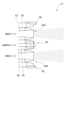
- FIGS 3 to 5 are each schematic diagrams showing a portion of a boiler according to one embodiment.
- the burner 21 of the boiler 10 includes an ammonia diffusion burner 70 for injecting liquid ammonia into the furnace 11, and an ammonia premixing burner 72 for injecting a premix of gaseous ammonia and air into the furnace 11.
- an ammonia diffusion burner 70 and the ammonia premixing burner 72 may be provided adjacent to each other.
- the burner 21 includes a pulverized fuel burner 50 for ejecting pulverized fuel (such as pulverized coal) together with air into the furnace 11.
- pulverized fuel burner 50 may be provided adjacent to either the ammonia diffusion burner 70 or the ammonia premix burner 72.
- the burner 21 includes an ammonia diffusion burner 70 obtained by modifying the central burner 60, and an ammonia premix burner 72 obtained by modifying the pulverized fuel burner 50B.
- the burner 21 shown in Figures 3 and 4 can be obtained by modifying the oil burner (central burner 60) including the oil nozzle 62 in the burner 21' shown in Figure 2 into an ammonia diffusion burner 70, and modifying the pulverized fuel burner 50B (the pulverized fuel burner adjacent to the oil burner) in the burner 21' shown in Figure 2 into an ammonia premix burner 72.
- the oil burner (central burner 60) including the oil nozzle 62 in the burner 21' shown in Figure 2 may be modified to an ammonia diffusion burner 70 by replacing the oil nozzle 62 of the burner 21' with a liquid ammonia nozzle 74 (see Figures 3 and 4) for spraying liquid ammonia into the furnace 11.
- the pulverized fuel burner 50B in the burner 21' shown in FIG. 2 may be modified to an ammonia premixed burner 72 by installing a premixed gas forming section 82 (see FIGS. 3 and 4) for forming a premixed gas of ammonia and air in the pulverized fuel burner 50B in the burner 21'.
- the premixed gas forming section 82 includes a premixed gas pipe 84 connected to the pulverized fuel supply pipe 22 and supplied with high-temperature (e.g., 200° C. or higher) heated air (e.g., secondary air from the air duct 24), and a liquid ammonia nozzle 86 for injecting liquid ammonia into the premixed gas pipe 84.
- the liquid ammonia injected into the heated air flow of the premixed gas pipe 84 is vaporized by the high-temperature heated air and mixed with the heated air to form a premixed gas.
- the premixed gas thus formed is supplied to the pulverized fuel nozzle 52 of the ammonia premixed burner 72 via the pulverized fuel supply pipe 22, and is injected from the pulverized fuel nozzle 52 into the furnace 11.
- the pulverized fuel supply pipe 22 may be provided with a gate valve 92 for switching between a supply state and a non-supply state of the pulverized fuel and primary air from the pulverized fuel supply pipe 22 to the furnace 11.
- the premixing pipe 84 may be provided with a gate valve 94 for switching between a supply state and a non-supply state of the premixed air from the premixing pipe 84 to the pulverized fuel supply pipe 22.
- the premixed gas forming section 82 includes a pulverized fuel supply pipe 22 and a gaseous ammonia supply pipe 110 connected to the pulverized fuel supply pipe 22 for supplying gaseous ammonia to the pulverized fuel supply pipe 22.
- the gaseous ammonia supply pipe 110 may be provided with a gate valve 112 for switching between a supply state and a non-supply state of gaseous ammonia from the gaseous ammonia supply pipe 110 to the pulverized fuel supply pipe 22.
- the gaseous ammonia supplied from the gaseous ammonia supply pipe 110 to the pulverized fuel supply pipe 22 is mixed with the primary air flowing through the pulverized fuel supply pipe 22 together with the pulverized fuel to form a premixed gas.
- the premixed gas thus formed is supplied to the pulverized fuel nozzle 52 of the ammonia premixed burner 72 via the pulverized fuel supply pipe 22 and sprayed from the pulverized fuel nozzle 52 into the furnace 11.
- the burner 21 includes an ammonia diffusion burner 70 obtained by modifying the pulverized fuel burner 50B, and an ammonia premix burner 72 obtained by modifying the central burner 60.
- the burner 21 shown in FIG. 5 can be obtained by modifying the oil burner (central burner 60) including the oil nozzle 62 in the burner 21' shown in FIG. 2 into an ammonia premix burner 72, and modifying the pulverized fuel burner 50B (the pulverized fuel burner adjacent to the oil burner) in the burner 21' shown in FIG. 2 into an ammonia diffusion burner 70.
- the oil burner (central burner 60) including the oil nozzle 62 in the burner 21' shown in FIG. 2 can be modified to an ammonia premixed burner 72 by removing the oil nozzle 62 from the burner 21', installing a gaseous ammonia nozzle 120 for spraying gaseous ammonia in the space formed by removing the oil nozzle 62, and forming a heated air flow path 118 around the gaseous ammonia nozzle 120 through which heated air (such as secondary air from the air duct 24) flows.
- the gaseous ammonia sprayed from the gaseous ammonia nozzle 120 is mixed with the heated air flowing through the heated air flow path 118 to form a premixed gas, and the premixed gas is sprayed into the furnace 11.
- the pulverized fuel burner 50B in the burner 21' shown in FIG. 2 may be modified to an ammonia diffusion burner 70 by replacing the pulverized fuel burner 50B in the burner 21' with a diffusion burner including a liquid ammonia nozzle 74 and an air nozzle 116.
- liquid ammonia from a liquid ammonia storage section 76 is supplied to the ammonia diffusion burner 70 via an ammonia line 78.
- the ammonia line 78 may be provided with a first valve 80 capable of adjusting the amount of ammonia supplied to the ammonia diffusion burner 70.
- the ammonia premixed burner 72 is supplied with a premix of ammonia and air formed from liquid ammonia supplied from the liquid ammonia reservoir 76 via an ammonia line 88.
- the ammonia line 88 may be provided with a second valve 90 capable of adjusting the amount of ammonia supplied to the ammonia premixed burner 72.
- the liquid ammonia from the liquid ammonia storage section 76 is supplied in a liquid state to the liquid ammonia nozzle 86 (premixed gas formation section 82) via the ammonia line 88.
- the liquid ammonia from the liquid ammonia storage section 76 is vaporized in the vaporizer 114 and then supplied to the gaseous ammonia supply pipe 110 (premixed gas formation section 82) or the gaseous ammonia nozzle 120 via the ammonia line 88.
- pulverized fuel from a pulverized fuel storage section 96 is supplied to the pulverized fuel burner 50A via a pulverized fuel line 98 and a pulverized fuel supply pipe 22.
- the pulverized fuel line 98 may be provided with a pulverized fuel valve 99 for adjusting the amount of pulverized fuel supplied to the pulverized fuel burner 50A.
- the boiler 10 may be equipped with a control device 200 (control unit) for adjusting the amount of ammonia supplied to the ammonia diffusion burner 70 via the ammonia line 78, the amount of ammonia supplied to the ammonia premix burner 72 via the ammonia line 88, and/or the amount of pulverized fuel supplied to the pulverized fuel burner 50A via the pulverized fuel line 98.
- the control device 200 may be configured to adjust the opening of the first valve 80, the second valve 90, and/or the pulverized fuel valve 99 so that the amount of each fuel supplied is a predetermined value.
- the control device 200 may include a computer equipped with a processor (CPU, etc.), a main memory device (memory device; RAM, etc.), an auxiliary memory device, and an interface.
- the control device 200 may receive target values of the amount of ammonia supplied to the ammonia diffusion burner 70 via the ammonia line 78, the amount of ammonia supplied to the ammonia premix burner 72 via the ammonia line 88, and/or the amount of pulverized fuel supplied to the pulverized fuel burner 50A via the pulverized fuel line 98 from a higher-level control device, etc.
- the control device 200 may be configured to adjust the opening of the first valve 80, the second valve 90, and/or the pulverized fuel valve 99 so that each supply amount approaches the target value.
- control device 200 may receive a required load of the boiler 10 from a higher-level control device, etc.
- the control device 200 may be configured to adjust the opening of the first valve 80, the second valve 90, and/or the pulverized fuel valve 99 so as to satisfy the required load.
- the ammonia diffusion burner 70 sprays ammonia in liquid form into the furnace 11, so that the amount of ammonia supply can be increased while suppressing the increase in size of the fuel piping, etc.
- the ammonia premix burner 72 which has relatively good ignition properties, is provided together with the ammonia diffusion burner 70, the deterioration of ignition properties and combustibility caused by using the ammonia diffusion burner 70 that sprays liquid ammonia can be suppressed. Therefore, according to the embodiment described above, it is possible to ensure both the amount of ammonia supply and ignition stability. Also, by providing the ammonia premix burner 72 in a position adjacent to the ammonia diffusion burner 70, the deterioration of ignition properties and combustibility caused by using the ammonia diffusion burner 70 that sprays liquid ammonia can be more effectively suppressed.
- the pulverized fuel burner 50A which has relatively good ignition properties, is provided, so that the deterioration of ignition properties and combustibility caused by using the ammonia diffusion burner 70 that ejects liquid ammonia can be more effectively suppressed.
- the pulverized fuel burner 50A is provided adjacent to either the ammonia diffusion burner 70 or the ammonia premixed burner 72, the deterioration of ignition properties and combustibility caused by using the ammonia diffusion burner 70 that ejects liquid ammonia can be more effectively suppressed.
- the pulverized fuel burner 50A is provided adjacent to the ammonia diffusion burner 70.
- the pulverized fuel burner 50A is provided adjacent to the ammonia premixed burner 72.
- the method for operating the boiler 10 described above can be performed using the control device 200 described above or manually.
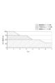
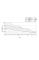
- FIG. 6 and 7 are graphs showing an example of the time change in the boiler load and the ratio of the heat input of the ammonia diffusion burner 70, the ammonia premixing burner 72, and the pulverized fuel burner 50A (i.e., the ratio of the supply amount of fuel (ammonia (NH 3 ) or pulverized fuel) supplied to each burner on a heat value basis) when carrying out a boiler operation method according to one embodiment.
- the boiler load is gradually reduced from 100% (rated load) to 25%.
- the diffused ammonia supply amount which is the amount of ammonia supplied to the furnace 11 via the ammonia diffusion burner 70
- the premixed ammonia supply amount which is the amount of ammonia supplied to the furnace 11 via the ammonia premixed burner 72
- the diffused ammonia supply amount is reduced in preference to the premixed ammonia supply amount. That is, in this embodiment, when the load of the boiler 10 is reduced, first, the diffused ammonia supply amount is reduced while maintaining the premixed ammonia supply amount, as shown in FIG. 6 and FIG. 7, and then, when the diffused ammonia supply amount approaches zero, the premixed ammonia supply amount is reduced.
- the diffusion ammonia supply amount is reduced in preference to the premixed ammonia supply amount, and the premixed ammonia supply amount is reduced in preference to the pulverized fuel supply amount. That is, in this embodiment, when the load of the boiler 10 is reduced, as shown in FIG. 6, first, the diffusion ammonia supply amount is reduced while maintaining the premixed ammonia supply amount and the pulverized fuel supply amount, and then, when the diffusion ammonia supply amount approaches zero, the premixed ammonia supply amount is reduced while maintaining the pulverized fuel, and further, when the premixed ammonia supply amount approaches zero, the pulverized fuel supply amount is reduced.
- the amount of diffused ammonia supplied to the ammonia diffusion burner which has relatively low ignition characteristics, is reduced in preference to the amount of premixed ammonia supplied to the ammonia premixed burner, which has relatively good ignition characteristics, and the amount of premixed ammonia supplied to the ammonia premixed burner is reduced in preference to the amount of pulverized fuel supplied to the pulverized fuel burner, which has better ignition characteristics. This makes it possible to further reduce the load on the boiler while maintaining ignition stability.
- the diffused ammonia supply amount is reduced in preference to the premixed ammonia supply amount while maintaining the ammonia co-firing ratio.
- the ammonia co-firing ratio is the ratio of the sum of the diffused ammonia supply amount and the premixed ammonia supply amount to the total of the diffused ammonia supply amount, the premixed ammonia supply amount, and the pulverized fuel supply amount, based on the heat amount. That is, in this embodiment, when the load of the boiler 10 is reduced, as shown in FIG.
- both the ammonia supply amount and the pulverized fuel supply amount are reduced while maintaining the ratio of the ammonia supply amount (the sum of the diffused ammonia supply amount and the premixed ammonia supply amount) to the pulverized fuel supply amount constant.
- the ammonia supply amount first the diffused ammonia supply amount is reduced while maintaining the premixed ammonia supply amount, and then when the diffused ammonia supply amount approaches zero, the premixed ammonia supply amount is reduced.
- the amount of diffused ammonia supplied to the ammonia diffusion burner 70 which has relatively low ignition characteristics, is reduced in priority to the amount of premixed ammonia supplied to the ammonia premix burner 72, which has relatively good ignition characteristics, while maintaining the ammonia co-firing ratio. This makes it possible to reduce the load on the boiler 10 while maintaining ignition stability and increasing the amount of ammonia input to the boiler 10 as much as possible.
- At least one embodiment of the boiler (10) of the present invention comprises: A furnace (11) for burning fuel; an ammonia diffusion burner (70) configured to inject liquid ammonia into the furnace; an ammonia premix burner (72) configured to inject a premix of gaseous ammonia and air into the furnace; Equipped with.
- the ammonia diffusion burner sprays ammonia in liquid form into the furnace, making it possible to increase the amount of ammonia supplied while preventing the need for larger fuel piping, etc. Furthermore, an ammonia premixed burner with relatively good ignition properties is provided in addition to the ammonia diffusion burner, making it possible to prevent a decrease in ignition and combustibility caused by the use of an ammonia diffusion burner that sprays liquid ammonia. Thus, with the configuration [1] above, it is possible to ensure both the amount of ammonia supplied and ignition stability.
- the boiler comprises:
- the apparatus further comprises a pulverized fuel burner (50A) configured to inject pulverized fuel into the furnace together with air.
- the configuration of [2] above provides a pulverized fuel burner with relatively good ignition properties in addition to the ammonia diffusion burner and the ammonia premix burner, so that it is possible to more effectively suppress the deterioration of ignition properties and combustibility caused by using the ammonia diffusion burner that sprays liquid ammonia. Therefore, the configuration of [2] above can ensure both the ammonia supply amount and ignition stability.
- the boiler comprises: A control unit (e.g., a control device 200) configured to adjust a diffusion ammonia supply amount, which is an ammonia supply amount to the furnace via the ammonia diffusion burner, and a premixed ammonia supply amount, which is an ammonia supply amount to the furnace via the ammonia premixed burner, based on a required load of the boiler;
- the control unit is configured to reduce the diffused ammonia supply rate in preference to the premixed ammonia supply rate when reducing a load on the boiler.
- the boiler comprises: A pulverized fuel burner configured to inject pulverized fuel together with air into the furnace;
- the control unit is configured to adjust a pulverized fuel supply amount to the furnace via the pulverized fuel burner in addition to the diffusion ammonia supply amount and the premixed ammonia supply amount;
- the control unit is configured to reduce the diffusion ammonia supply amount in preference to the premixed ammonia supply amount and to reduce the premixed ammonia supply amount in preference to the pulverized fuel supply amount when reducing a load on the boiler.
- the amount of diffused ammonia supplied to the ammonia diffusion burner which has relatively low ignition characteristics, is reduced in preference to the amount of premixed ammonia supplied to the ammonia premixed burner, which has relatively good ignition characteristics, and the amount of premixed ammonia supplied to the ammonia premixed burner is reduced in preference to the amount of pulverized fuel supplied to the pulverized fuel burner, which has better ignition characteristics. This makes it possible to further reduce the load on the boiler while maintaining ignition stability.
- the boiler comprises: A pulverized fuel burner configured to inject pulverized fuel together with air into the furnace;
- the control unit is configured to adjust a pulverized fuel supply amount to the furnace via the pulverized fuel burner in addition to the diffusion ammonia supply amount and the premixed ammonia supply amount;
- the control unit is configured to reduce the diffused ammonia supply amount in preference to the premixed ammonia supply amount while maintaining an ammonia co-firing ratio when reducing a load of the boiler,
- the ammonia co-firing ratio is a ratio on a calorific value basis of the sum of the diffusion ammonia supply amount and the premixed ammonia supply amount to the total of the diffusion ammonia supply amount, the premixed ammonia supply amount, and the pulverized fuel supply amount.
- a method for retrofitting a boiler includes the steps of: A method for retrofitting a boiler including a furnace (11), an oil burner (e.g., a central burner 60) for injecting oil into the furnace, and a pulverized fuel burner (50B) for injecting pulverized fuel together with air into the furnace, comprising: converting the oil burner into an ammonia diffusion burner (70) for injecting liquid ammonia into the furnace; converting the pulverized fuel burner (72) into an ammonia premix burner (73) for injecting a premix of gaseous ammonia and air into the furnace; Equipped with.
- the oil burner is converted into an ammonia diffusion burner and the pulverized fuel burner is converted into an ammonia premix burner, thereby obtaining a boiler having the configuration of [1] above.
- the boiler obtained in this way can ensure both ammonia supply and ignition stability.
- an oil nozzle of the oil burner is replaced with a liquid ammonia nozzle (74) for spraying liquid ammonia into the furnace;
- a premixed gas forming section (82) for forming a premixed gas of gaseous ammonia and air is provided in the pulverized fuel burner.
- a method for retrofitting a boiler includes the steps of: A method for retrofitting a boiler including a furnace (11), an oil burner (e.g., a central burner 60) for injecting oil into the furnace, and a pulverized fuel burner (50B) for injecting pulverized fuel together with air into the furnace, comprising: converting the oil burner into an ammonia premix burner (72) for injecting a premix of gaseous ammonia and air into the furnace; converting the pulverized fuel burner into an ammonia diffusion burner (70) for injecting liquid ammonia into the furnace; Equipped with.
- the oil burner is converted into an ammonia premix burner and the pulverized fuel burner into an ammonia diffusion burner, thereby obtaining a boiler having the configuration of [1] above.
- the boiler obtained in this way can ensure both the ammonia supply amount and ignition stability.
- a method for operating a boiler according to at least one embodiment of the present invention includes: A method for operating a boiler according to any one of the above [1] to [5], The method includes a step of adjusting a diffusion ammonia supply amount, which is an ammonia supply amount to the furnace via the ammonia diffusion burner, and a premixed ammonia supply amount, which is an ammonia supply amount to the furnace via the ammonia premixing burner, based on a required load of the boiler; In the step, when the load of the boiler is reduced, the diffused ammonia supply amount is reduced in preference to the premixed ammonia supply amount.
- the amount of diffused ammonia supplied to the ammonia diffusion burner which has relatively low ignition characteristics, is reduced in priority to the amount of premixed ammonia supplied to the ammonia premixed burner, which has relatively good ignition characteristics, so that the load on the boiler can be reduced while maintaining ignition stability.
- expressions expressing relative or absolute configuration do not only strictly represent such a configuration, but also represent a state in which there is a relative displacement with a tolerance or an angle or distance to the extent that the same function is obtained.
- expressions indicating that things are in an equal state such as “identical,””equal,” and “homogeneous,” not only indicate a state of strict equality, but also indicate a state in which there is a tolerance or a difference to the extent that the same function is obtained.
- expressions describing shapes such as a rectangular shape or a cylindrical shape do not only refer to shapes such as a rectangular shape or a cylindrical shape in the strict geometric sense, but also refer to shapes that include uneven portions, chamfered portions, etc., to the extent that the same effect is obtained.
- the expressions "comprise,””include,” or “have” a certain element are not exclusive expressions that exclude the presence of other elements.
Landscapes
- Engineering & Computer Science (AREA)
- Mechanical Engineering (AREA)
- General Engineering & Computer Science (AREA)
- Chemical & Material Sciences (AREA)
- Combustion & Propulsion (AREA)
- Combustion Of Fluid Fuel (AREA)
- Gas Burners (AREA)
Abstract
ボイラは、燃料を燃焼させるための火炉と、液体アンモニアを前記火炉に噴出するように構成されたアンモニア拡散バーナと、気体アンモニアと空気の予混合気を前記火炉に噴出するように構成されたアンモニア予混合バーナと、を備える。
Description
本開示は、ボイラ、ボイラの改造方法及びボイラの運転方法に関する。
本願は、2023年6月29日に日本国特許庁に出願された特願2023-107471号に基づき優先権を主張し、その内容をここに援用する。
本願は、2023年6月29日に日本国特許庁に出願された特願2023-107471号に基づき優先権を主張し、その内容をここに援用する。
燃料としてのアンモニアを燃焼させるバーナを備えたボイラが知られている。
特許文献1には、アンモニア及び微粉炭を燃焼させるバーナを備えたボイラが記載されている。
ところで、燃料配管等の大型化を抑制しつつアンモニア供給量を確保するためには、気体アンモニアを火炉に供給するのに比べて、アンモニアを液体のまま火炉に供給して拡散燃焼させるのが有利である。一方、アンモニアはメタン等の一般的な炭化水素燃料と比べて燃焼速度が低く、着火及び燃焼し難い性質を持つ。さらに、液体アンモニアは気化熱が大きいため、着火性が低下すると考えられる。そこで、アンモニアを燃料とするボイラにおいて、アンモニア供給量の確保と着火安定性を両立可能であることが望まれる。
上述の事情に鑑みて、本発明の少なくとも一実施形態は、アンモニア供給量の確保と着火安定性を両立可能なボイラ、ボイラの改造方法及びボイラの運転方法を提供することを目的とする。
本発明の少なくとも一実施形態に係るボイラは、
燃料を燃焼させるための火炉と、
液体アンモニアを前記火炉に噴出するように構成されたアンモニア拡散バーナと、
気体アンモニアと空気の予混合気を前記火炉に噴出するように構成されたアンモニア予混合バーナと、
を備える。
燃料を燃焼させるための火炉と、
液体アンモニアを前記火炉に噴出するように構成されたアンモニア拡散バーナと、
気体アンモニアと空気の予混合気を前記火炉に噴出するように構成されたアンモニア予混合バーナと、
を備える。
また、本発明の少なくとも一実施形態に係るボイラの改造方法は、
火炉と、前記火炉に油を噴出させるための油バーナと、前記火炉に微粉燃料を空気とともに噴出させるための微粉燃料バーナと、を含むボイラの改造方法であって、
前記油バーナを、液体アンモニアを前記火炉に噴出するためのアンモニア拡散バーナに改造するステップと、
前記微粉燃料バーナを、気体アンモニアと空気の予混合気を前記火炉に噴出するためのアンモニア予混合バーナに改造するステップと、
を備える。
火炉と、前記火炉に油を噴出させるための油バーナと、前記火炉に微粉燃料を空気とともに噴出させるための微粉燃料バーナと、を含むボイラの改造方法であって、
前記油バーナを、液体アンモニアを前記火炉に噴出するためのアンモニア拡散バーナに改造するステップと、
前記微粉燃料バーナを、気体アンモニアと空気の予混合気を前記火炉に噴出するためのアンモニア予混合バーナに改造するステップと、
を備える。
また、本発明の少なくとも一実施形態に係るボイラの改造方法は、
火炉と、前記火炉に油を噴出させるための油バーナと、前記火炉に微粉燃料を空気とともに噴出させるための微粉燃料バーナと、を含むボイラの改造方法であって、
前記油バーナを、気体アンモニアと空気の予混合気を前記火炉に噴出するためのアンモニア予混合バーナに改造するステップと、
前記微粉燃料バーナを、液体アンモニアを前記火炉に噴出するためのアンモニア拡散バーナに改造するステップと、
を備える。
火炉と、前記火炉に油を噴出させるための油バーナと、前記火炉に微粉燃料を空気とともに噴出させるための微粉燃料バーナと、を含むボイラの改造方法であって、
前記油バーナを、気体アンモニアと空気の予混合気を前記火炉に噴出するためのアンモニア予混合バーナに改造するステップと、
前記微粉燃料バーナを、液体アンモニアを前記火炉に噴出するためのアンモニア拡散バーナに改造するステップと、
を備える。
また、本発明の少なくとも一実施形態に係るボイラの運転方法は、
上述のボイラの運転方法であって、
前記ボイラの要求負荷に基づいて、前記アンモニア拡散バーナを介した前記火炉へのアンモニア供給量である拡散アンモニア供給量、及び、前記アンモニア予混合バーナを介した前記火炉へのアンモニア供給量である予混合アンモニア供給量を調節するステップを備え、
前記ステップでは、前記ボイラの負荷を減少させるとき、前記予混合アンモニア供給量に優先して前記拡散アンモニア供給量を減少させる。
上述のボイラの運転方法であって、
前記ボイラの要求負荷に基づいて、前記アンモニア拡散バーナを介した前記火炉へのアンモニア供給量である拡散アンモニア供給量、及び、前記アンモニア予混合バーナを介した前記火炉へのアンモニア供給量である予混合アンモニア供給量を調節するステップを備え、
前記ステップでは、前記ボイラの負荷を減少させるとき、前記予混合アンモニア供給量に優先して前記拡散アンモニア供給量を減少させる。
本発明の少なくとも一実施形態によれば、アンモニア供給量の確保と着火安定性を両立可能なボイラ、ボイラの改造方法及びボイラの運転方法が提供される。
以下、添付図面を参照して本発明の幾つかの実施形態について説明する。ただし、実施形態として記載されている又は図面に示されている構成部品の寸法、材質、形状、その相対的配置等は、本発明の範囲をこれに限定する趣旨ではなく、単なる説明例にすぎない。以降の説明で、上や上方とは鉛直方向上側を示し、下や下方とは鉛直方向下側を示すものであり、鉛直方向は厳密ではなく誤差を含むものである。
(ボイラ及びバーナの構成)
図1は、一実施形態に係るボイラを示す概略構成図である。
図1は、一実施形態に係るボイラを示す概略構成図である。
図1に示すように、一実施形態に係るボイラ10は、固体燃料を粉砕した微粉燃料をバーナにより燃焼させ、この燃焼により発生した熱を給水や蒸気と熱交換して過熱蒸気を生成することが可能なボイラである。固体燃料としては、バイオマス燃料や石炭などが使用される。
ボイラ10は、火炉11と燃焼装置20と燃焼ガス通路12を有している。火炉11は、四角筒の中空形状をなして鉛直方向に沿って設置されている。火炉11の内壁面を構成する火炉壁101は、複数の伝熱管と、伝熱管同士を接続するフィンとで構成され、微粉燃料の燃焼により発生した熱を、伝熱管の内部を流通する水や蒸気と熱交換して回収すると共に、火炉壁101の温度上昇を抑制している。
燃焼装置20は、火炉11の下部領域に設置されている。本実施形態では、燃焼装置20は、火炉壁101に装着された複数のバーナ21A、21B、21C、21D、21E、21F(以下、一括して「バーナ21」と記載する場合がある。)を有している。バーナ21は、火炉11の周方向に沿って均等間隔で配設されたもの(例えば、四角形の火炉11の各コーナ部に設置された4個)を1セットとして、鉛直方向に沿って複数段配置されたものであってもよい。なお、図1では、図示の都合上、1セットのバーナのうちの2個のみを記載し、各セットに符合21A、21B、21C、21D、21E、21Fを付している。火炉の形状やバーナの段数、一つの段におけるバーナの数、バーナの配置などは、この実施形態に限定されるものではない。
例えば、燃焼装置20は、上述のように、複数のバーナ21が火炉11の周方向に沿って均等配置され、火炉11の上下方向に延びる中心線の周りに周方向に沿って燃料を噴出するように構成された、旋回燃焼方式の燃焼装置であってもよい。
バーナ21A、21B、21C、21D、21E、21Fは、それぞれ、複数の微粉燃料供給管22A、22B、22C、22D、22E、22F(以下、一括して「微粉燃料供給管22」と記載する場合がある。)を介して、複数のミル(粉砕機)31A、31B、31C、31D、31E、31F(以下、一括して「ミル31」と記載する場合がある。)に連結されている。ミル31は、例えば、内部に粉砕テーブル(図示省略)が駆動回転可能に支持されていて、粉砕テーブルの上方に複数の粉砕ローラ(図示省略)が粉砕テーブルの回転に連動回転可能に支持されて構成されている竪型ローラミルである。粉砕ローラと粉砕テーブルが協働して粉砕された固体燃料は、ミル31に供給される一次空気(搬送用ガス、酸化性ガス)により、ミル31が備える分級機(図示省略)に搬送される。分級機では、バーナ21での燃焼に適した粒径以下の微粉燃料と、該粒径より大きな粗粉燃料とに分級される。微粉燃料は、分級機を通過して、一次空気と共に微粉燃料供給管22を介してバーナ21に供給される。分級機を通過しなかった粗粉燃料は、ミル31の内部で、自重により粉砕テーブル上に落下し、再粉砕される。
バーナ21の装着位置における火炉11の炉外側には、風箱(エアレジスタ)23が設けられており、この風箱23には風道(空気ダクト)24の一端部が連結されている。風道24の他端部には、押込通風機(FDF:Forced Draft Fan)32が連結されている。押込通風機32から供給された空気は、風道24に設置された空気予熱器42で加熱され(詳細は後述する)、風箱23を介してバーナ21に二次空気(燃焼用空気、酸化性ガス)として供給され、火炉11の内部に投入される。
燃焼ガス通路12は、火炉11の鉛直方向上部に連結されている。燃焼ガス通路12には、燃焼ガスの熱を回収するための熱交換器として、過熱器102A、102B、102C(以下、一括して「過熱器102」と記載する場合がある。)、再熱器103A、103B(以下、一括して「再熱器103」と記載する場合がある。)、節炭器104が設けられており、火炉11で発生した燃焼ガスと各熱交換器の内部を流通する給水や蒸気との間で熱交換が行われる。なお、各熱交換器の配置や形状は、図1に記載した形態に限定されない。
燃焼ガス通路12の下流側には、熱交換器で熱回収された燃焼ガスが排出される煙道13が連結されている。煙道13には、風道24との間に空気予熱器(エアヒータ)42が設けられており、風道24を流れる空気と、煙道13を流れる燃焼ガスとの間で熱交換を行い、ミル31に供給する一次空気やバーナ21に供給する二次空気を加熱することで、水や蒸気との熱交換後の燃焼ガスから、さらに熱回収を行う。
また、煙道13には、空気予熱器42よりも上流側の位置に、脱硝装置43が設けられていてもよい。脱硝装置43は、アンモニア、尿素水等の窒素酸化物を還元する作用を有する還元剤を、煙道13内を流通する燃焼ガスに供給し、還元剤が供給された燃焼ガス中の窒素酸化物(NOx)と還元剤との反応を、脱硝装置43内に設置された脱硝触媒の触媒作用により促進させることで、燃焼ガス中の窒素酸化物を除去、低減するものである。煙道13の空気予熱器42より下流側には、ガスダクト41が連結されている。ガスダクト41には、燃焼ガス中の灰などを除去する電気集じん機などの集じん装置44や硫黄酸化物を除去する脱硫装置46などの環境装置、また、それらの環境装置に排ガスを導くための誘引通風機(IDF:Induced Draft Fan)45が設けられている。ガスダクト41の下流端部は、煙突47に連結されており、環境装置で処理された燃焼ガスが、排ガスとして系外に排出される。
ボイラ10において、複数のミル31が駆動すると、粉砕、分級された微粉燃料が、一次空気と共に微粉燃料供給管22を介してバーナ21に供給される。また、空気予熱器42で加熱された二次空気が、風道24から風箱23を介してバーナ21に供給される。バーナ21は、微粉燃料と一次空気とが混合した微粉燃料混合気を火炉11に吹き込むと共に、二次空気を火炉11に吹き込む。火炉11に吹き込まれた微粉燃料混合気が着火し、二次空気と反応することで火炎を形成する。火炉11内の下部領域で火炎が形成され、高温の燃焼ガスが火炉11内を上昇し、燃焼ガス通路12に流入する。なお、本実施形態では、酸化性ガス(一次空気、二次空気)として空気を用いるが、空気よりも酸素割合が多いものや逆に少ないものであってもよく、供給される燃料量に対する酸素量の比率を適正な範囲に調整することで、火炉11において安定した燃焼が実現される。
燃焼ガス通路12に流入した燃焼ガスは、燃焼ガス通路12の内部に配置された過熱器102、再熱器103、節炭器104で水や蒸気と熱交換した後、煙道13に排出され、脱硝装置43で窒素酸化物が除去され、空気予熱器42で一次空気及び二次空気と熱交換した後、さらにガスダクト41に排出され、集じん装置44で灰などが除去され、脱硫装置46で硫黄酸化物が除去された後、煙突47から系外に排出される。なお、燃焼ガス通路12における各熱交換器及び煙道13からガスダクト41における各装置の配置は、燃焼ガス流れに対して、必ずしも上述の記載順に配置されなくともよい。
上述した実施形態では、本発明のボイラを、燃料に固体燃料を使用するボイラとして説明した。ボイラに使用される固体燃料としては、石炭、バイオマス燃料、石油コークス(PC:Petroleum Coke)燃料、石油残渣などが使用される。
なお、ボイラの燃料としては、固体燃料に限らず、重油、軽油、重質油などの石油類や工場廃液、液化アンモニアなどの液体燃料も使用することができる。また、天然ガスや各種石油ガス、製鉄プロセスなどで発生する副生ガス、水素ガス、アンモニアガスなどの気体燃料も使用することができる。
さらに、これらの各種燃料を組み合わせて使用する混焼ボイラにも適用することができる。
幾つかの実施形態に係るボイラ10は、少なくともアンモニアを燃焼させるように構成される。
図2は、図1に示すボイラ10に適用可能なバーナ21’の概略図である。幾つかの実施形態に係るバーナ21は、以下に説明するバーナ21’を改造することにより得ることができる。
図2に示すように、バーナ21’(上述のバーナ21A~21Fの各々に対応する)は、上下方向における中央部に位置する中央バーナ60と、中央バーナ60の上下に位置する微粉燃料バーナ50A,50B(以下、微粉燃料バーナ50と総称する)を備えている。また、これらのバーナ群(中央バーナ60及び微粉燃料バーナ50A、50B)の上下には、燃焼用空気ノズル56が設けられている。
微粉燃料バーナ50は、微粉燃料ノズル52と、空気ノズル54と、を含む。微粉燃料ノズル52は、微粉燃料供給管22から供給される一次空気及び該一次空気によって搬送される微粉燃料(微粉炭等)を火炉11に吹き込むようになっている。空気ノズル54は、空気ダクト24から供給される二次空気(エアヒータ42で加熱された加熱空気)を火炉11に吹き込むようになっている。
中央バーナ60は、拡散燃焼用の燃料を空気とともに火炉11に吹き込むようになっている。図2に示す例では、中央バーナ60は、油燃料を火炉11に吹き込むように構成された油ノズル62と、油ノズル62の周囲を囲むように設けられる空気ノズル66と、を含む。空気ノズル66は、空気ダクト24から供給される二次空気(エアヒータ42で加熱された加熱空気)を火炉11に吹き込むように構成されていてもよい。
燃焼用空気ノズル56は、空気ダクト24から供給される二次空気(エアヒータ42で加熱された加熱空気)を火炉11に吹き込むように構成されていてもよい。
次に、幾つかの実施形態に係るボイラ及びバーナについてより具体的に説明する。図3~図5は、それぞれ、一実施形態に係るボイラの一部を示す概略図である。
図3~図5に示す実施形態に係るボイラ10のバーナ21は、液体アンモニアを火炉11に噴出するためのアンモニア拡散バーナ70と、気体アンモニアと空気の予混合気を火炉11に噴出するためのアンモニア予混合バーナ72と、を備えている。図示するように、アンモニア拡散バーナ70とアンモニア予混合バーナ72は、互いに隣り合うように設けられていてもよい。
また、図3~図5に示す例示的な実施形態では、バーナ21は、微粉燃料(微粉炭等)を空気とともに火炉11に噴出するための微粉燃料バーナ50を備えている。図示するように、微粉燃料バーナ50は、アンモニア拡散バーナ70又はアンモニア予混合バーナ72の一方と隣り合うように設けられていてもよい。
図3及び図4に示す例示的な実施形態では、バーナ21は、中央バーナ60を改造して得られるアンモニア拡散バーナ70と、微粉燃料バーナ50Bを改造して得られるアンモニア予混合バーナ72と、を含む。
すなわち、図3及び図4に示すバーナ21は、図2に示すバーナ21’における油ノズル62を含む油バーナ(中央バーナ60)をアンモニア拡散バーナ70に改造するとともに、図2に示すバーナ21’における微粉燃料バーナ50B(油バーナと隣り合う微粉燃料バーナ)をアンモニア予混合バーナ72に改造することで得ることがでできる。
図2に示すバーナ21’における油ノズル62を含む油バーナ(中央バーナ60)のアンモニア拡散バーナ70への改造は、バーナ21’の油ノズル62を、液体アンモニアを火炉11に噴出するための液体アンモニアノズル74(図3及び図4参照)に交換することで行ってもよい。
図2に示すバーナ21’における微粉燃料バーナ50Bのアンモニア予混合バーナ72への改造は、バーナ21’における微粉燃料バーナ50Bに、気体アンモニアと空気の予混合気を形成するための予混合気形成部82(図3及び図4参照)を設置することで行ってもよい。
図3に示す例示的な実施形態では、予混合気形成部82は、微粉燃料供給管22に接続され、高温(例えば200℃以上)の加熱空気(例えば空気ダクト24からの二次空気)が供給される予混合気管84と、予混合気管84の内部に液体アンモニアを噴出するための液体アンモニアノズル86と、を含む。予混合気管84の加熱空気流れに噴出された液体アンモニアは、高温の加熱空気によって気化され、加熱空気と混合されて予混合気が形成される。このように形成された予混合気は、微粉燃料供給管22を介してアンモニア予混合バーナ72の微粉燃料ノズル52に供給され、該微粉燃料ノズル52から火炉11に噴出される。
なお、微粉燃料供給管22には、微粉燃料供給管22から火炉11への微粉燃料及び一次空気の供給状態と非供給状態とを切替えるためのゲート弁92が設けられていてもよい。また、予混合気管84には、予混合気管84から微粉燃料供給管22への予混合気の供給状態と非供給状態とを切替えるためのゲート弁94が設けられていてもよい。
図4に示す例示的な実施形態では、予混合気形成部82は、微粉燃料供給管22と、微粉燃料供給管22に接続され、微粉燃料供給管22に気体アンモニアを供給するための気体アンモニア供給管110と、を含む。気体アンモニア供給管110には、気体アンモニア供給管110から微粉燃料供給管22への気体アンモニアの供給状態と非供給状態とを切替えるためのゲート弁112が設けられていてもよい。気体アンモニア供給管110から微粉燃料供給管22に供給された気体アンモニアは、微粉燃料供給管22を微粉燃料とともに流れる一次空気と混合され、予混合気が形成される。このように形成された予混合気は、微粉燃料供給管22を介してアンモニア予混合バーナ72の微粉燃料ノズル52に供給され、該微粉燃料ノズル52から火炉11に噴出される。
図5に示す例示的な実施形態では、バーナ21は、微粉燃料バーナ50Bを改造して得られるアンモニア拡散バーナ70と、中央バーナ60を改造して得られるアンモニア予混合バーナ72と、を含む。
すなわち、図5に示すバーナ21は、図2に示すバーナ21’における油ノズル62を含む油バーナ(中央バーナ60)をアンモニア予混合バーナ72に改造するとともに、図2に示すバーナ21’における微粉燃料バーナ50B(油バーナと隣り合う微粉燃料バーナ)をアンモニア拡散バーナ70に改造することで得ることがでできる。
図2に示すバーナ21’における油ノズル62を含む油バーナ(中央バーナ60)のアンモニア予混合バーナ72への改造は、バーナ21’の油ノズル62を取り外し、油ノズル62を取り外すことで形成されるスペースに、気体アンモニアを噴出するための気体アンモニアノズル120を設置するとともに、気体アンモニアノズル120の周囲に、加熱空気(空気ダクト24からの二次空気等)が流れる加熱空気流路118を形成することで行ってもよい。気体アンモニアノズル120から噴出される気体アンモニアは、加熱空気流路118を流れる加熱空気と混合されて予混合気が形成され、該予混合気が火炉11に噴出される。
図2に示すバーナ21’における微粉燃料バーナ50Bのアンモニア拡散バーナ70への改造は、バーナ21’における微粉燃料バーナ50Bを、液体アンモニアノズル74を及び空気ノズル116含む拡散バーナに交換することで行ってもよい。
図3~5に示すように、アンモニア拡散バーナ70には、液体アンモニア貯留部76からの液体アンモニアが、アンモニアライン78を介して供給されるようになっている。アンモニアライン78には、アンモニア拡散バーナ70へのアンモニアの供給量を調節可能な第1バルブ80が設けられていてもよい。
図3~図5に示すように、アンモニア予混合バーナ72には、液体アンモニア貯留部76からアンモニアライン88を介して供給される液体アンモニアから形成されるアンモニアと空気の予混合気が供給されるようになっている。アンモニアライン88には、アンモニア予混合バーナ72へのアンモニアの供給量を調節可能な第2バルブ90が設けられていてもよい。
図3に示す例示的な実施形態では、液体アンモニア貯留部76からの液体アンモニアは、液体状態のままでアンモニアライン88を介して液体アンモニアノズル86(予混合気形成部82)に供給されるようになっている。
図4及び図5に示す例示的な実施形態では、液体アンモニア貯留部76からの液体アンモニアは、気化器114で気化された後、アンモニアライン88を介して気体アンモニア供給管110(予混合気形成部82)又は気体アンモニアノズル120に供給されるようになっている。
図3~図5に示すように、微粉燃料バーナ50Aには、微粉燃料貯留部96からの微粉燃料が微粉燃料ライン98及び微粉燃料供給管22を介して供給されるようになっている。微粉燃料ライン98には、微粉燃料バーナ50Aへの微粉燃料の供給量を調節するための微粉燃料バルブ99が設けられていてもよい。
図3~図5に示すように、ボイラ10は、アンモニアライン78を介したアンモニア拡散バーナ70へのアンモニア供給量、アンモニアライン88を介したアンモニア予混合バーナ72へのアンモニア供給量、及び/又は、微粉燃料ライン98を介した微粉燃料バーナ50Aへの微粉燃料供給量を調節するための制御装置200(制御部)を備えていてもよい。制御装置200は、各燃料の供給量が所定値となるように、第1バルブ80、第2バルブ90及び/又は微粉燃料バルブ99の開度を調節するように構成されていてもよい。
制御装置200は、プロセッサ(CPU等)、主記憶装置(メモリデバイス;RAM等)、補助記憶装置及びインターフェース等を備えた計算機を含んでいてもよい。制御装置200は、上位制御装置等から、アンモニアライン78を介したアンモニア拡散バーナ70へのアンモニア供給量、アンモニアライン88を介したアンモニア予混合バーナ72へのアンモニア供給量、及び/又は、微粉燃料ライン98を介した微粉燃料バーナ50Aへの微粉燃料供給量の目標値を受け取るようになっていてもよい。制御装置200は、各供給量が目標値に近づくように、第1バルブ80、第2バルブ90及び/又は微粉燃料バルブ99の開度を調節するように構成されていてもよい。あるいは、制御装置200は、上位制御装置等から、ボイラ10の要求負荷を受け取るようになっていてもよい。制御装置200は、該要求負荷を満たすように、第1バルブ80、第2バルブ90及び/又は微粉燃料バルブ99の開度を調節するように構成されていてもよい。
上述の実施形態に係るボイラ10では、アンモニア拡散バーナ70でアンモニアを液体のまま火炉11に噴出するので、燃料配管等の大型化を抑制しつつアンモニア供給量を多くすることができる。また、アンモニア拡散バーナ70とともに、着火性が比較的良好なアンモニア予混合バーナ72を設けたので、液体アンモニアを噴出させるアンモニア拡散バーナ70を用いることによる着火性及び燃焼性の低下を抑制することができる。よって、上述の実施形態によれば、アンモニア供給量の確保と着火安定性を両立することができる。また、アンモニア予混合バーナ72をアンモニア拡散バーナ70と隣合う位置に設けることで、液体アンモニアを噴出させるアンモニア拡散バーナ70を用いることによる着火性及び燃焼性の低下をより効果的に抑制することができる。
また、上述の実施形態に係るボイラ10では、アンモニア拡散バーナ70及びアンモニア予混合バーナ72に加え、着火性が比較的良好な微粉燃料バーナ50Aを設けたので、液体アンモニアを噴出させるアンモニア拡散バーナ70を用いることによる着火性及び燃焼性の低下をより効果的に抑制することができる。また、微粉燃料バーナ50Aをアンモニア拡散バーナ70又はアンモニア予混合バーナ72の一方と隣り合う位置に設けることで、液体アンモニアを噴出させるアンモニア拡散バーナ70を用いることによる着火性及び燃焼性の低下をさらに効果的に抑制することができる。なお、図3及び図4に示す例示的な実施形態では、微粉燃料バーナ50Aは、アンモニア拡散バーナ70と隣り合うように設けられている。また、図5に示す例示的な実施形態では、微粉燃料バーナ50Aは、アンモニア予混合バーナ72と隣り合うように設けられている。
次に、幾つかの実施形態に係る上述のボイラ10の運転方法について説明する。以下に説明する運転方法は、上述の制御装置200を用いて、又は、手動で実行することができる。
図6及び図7は、それぞれ、一実施形態に係るボイラの運転方法を実施するときの、ボイラ負荷、及び、アンモニア拡散バーナ70、アンモニア予混合バーナ72及び微粉燃料バーナ50Aの入熱量の割合(即ち、各バーナに供給される燃料(アンモニア(NH3)又は微粉燃料)の熱量ベースでの供給量の割合)の時間変化の一例を示すグラフである。なお、図6及び図7のグラフでは、ボイラ負荷を100%(定格負荷)から25%まで段階的に低下させている。
幾つかの実施形態に係るボイラ10の運転方法では、ボイラ10の要求負荷に基づいて、アンモニア拡散バーナ70を介した火炉11へのアンモニア供給量である拡散アンモニア供給量、及び、アンモニア予混合バーナ72を介した火炉11へのアンモニア供給量である予混合アンモニア供給量を調節する。ここで、要求負荷に基づいてボイラ10の負荷を減少させるときには、予混合アンモニア供給量に優先して拡散アンモニア供給量を減少させる。即ち、本実施形態では、ボイラ10の負荷を減少させるとき、図6及び図7に示すように、先ず、予混合アンモニア供給量を維持したまま拡散アンモニア供給量を減少させ、次に、拡散アンモニア供給量がゼロに近づいたら、予混合アンモニア供給量を減少させる。
上述の運転方法では、ボイラ10の負荷を減少させるとき、着火性が比較的良好なアンモニア予混合バーナ72への予混合アンモニア供給量に優先して、着火性が比較的低いアンモニア拡散バーナ70への拡散アンモニア供給量を減少させるようにしたので、着火安定性を維持しながらボイラ10の負荷を低下させることができる。
一実施形態では、要求負荷に基づいてボイラ10の負荷を減少させるとき、予混合アンモニア供給量に優先して拡散アンモニア供給量を減少させるとともに、微粉燃料供給量に優先して予混合アンモニア供給量を減少させる。即ち、本実施形態では、ボイラ10の負荷を減少させるとき、図6に示すように、先ず、予混合アンモニア供給量及び微粉燃料供給量を維持したまま拡散アンモニア供給量を減少させ、次に、拡散アンモニア供給量がゼロに近づいたら、微粉燃料を維持したまま予混合アンモニア供給量を減少させ、さらに、予混合アンモニア供給量がゼロに近づいたら、微粉燃料供給量を減少させる。
上述の実施形態によれば、ボイラ10の負荷を減少させるとき、着火性が比較的良好なアンモニア予混合バーナへの予混合アンモニア供給量に優先して、着火性が比較的低いアンモニア拡散バーナへの拡散アンモニア供給量を減少させるとともに、着火性がより良好な微粉燃料バーナへの微粉燃料供給量に優先してアンモニア予混合バーナへの予混合アンモニア供給量を減少させるようにしたので、着火安定性を維持しながらボイラの負荷をさらに低下させることができる。
一実施形態では、要求負荷に基づいてボイラ10の負荷を減少させるとき、アンモニア混焼率を維持しながら予混合アンモニア供給量に優先して前記拡散アンモニア供給量を減少させる。ここで、アンモニア混焼率とは、拡散アンモニア供給量、予混合アンモニア供給量及び微粉燃料供給量の合計に対する拡散アンモニア供給量と予混合アンモニア供給量の和の熱量ベースの割合である。即ち、本実施形態では、ボイラ10の負荷を減少させるとき、図7に示すように、アンモニア供給量(拡散アンモニア供給量と予混合アンモニア供給量の和)と、微粉燃料供給量の比率を一定に維持しながら、アンモニア供給量及び微粉燃料供給量の両方を低下させる。また、アンモニア供給量については、先ず予混合アンモニア供給量を維持したまま拡散アンモニア供給量を減少させ、次に、拡散アンモニア供給量がゼロに近づいたら、予混合アンモニア供給量を減少させる。
上述の実施形態によれば、ボイラ10の負荷を減少させるとき、アンモニア混焼率を維持しながら、着火性が比較的良好なアンモニア予混合バーナ72への予混合アンモニア供給量に優先して、着火性が比較的低いアンモニア拡散バーナ70への拡散アンモニア供給量を減少させるようにしたので、ボイラ10へのアンモニア投入量をなるべく多くしつつ、着火安定性を維持しながらボイラ10の負荷を低下させることができる。
上記各実施形態に記載の内容は、例えば以下のように把握される。
[1]本発明の少なくとも一実施形態に係るボイラ(10)は、
燃料を燃焼させるための火炉(11)と、
液体アンモニアを前記火炉に噴出するように構成されたアンモニア拡散バーナ(70)と、
気体アンモニアと空気の予混合気を前記火炉に噴出するように構成されたアンモニア予混合バーナ(72)と、
を備える。
燃料を燃焼させるための火炉(11)と、
液体アンモニアを前記火炉に噴出するように構成されたアンモニア拡散バーナ(70)と、
気体アンモニアと空気の予混合気を前記火炉に噴出するように構成されたアンモニア予混合バーナ(72)と、
を備える。
上記[1]の構成では、アンモニア拡散バーナでアンモニアを液体のまま火炉に噴出するので、燃料配管等の大型化を抑制しつつアンモニア供給量を多くすることができる。また、アンモニア拡散バーナとともに、着火性が比較的良好なアンモニア予混合バーナを設けたので、液体アンモニアを噴出させるアンモニア拡散バーナを用いることによる着火性及び燃焼性の低下を抑制することができる。よって、上記[1]の構成によれば、アンモニア供給量の確保と着火安定性を両立することができる。
[2]幾つかの実施形態では、上記[1]の構成において、
前記ボイラは、
微粉燃料を空気とともに前記火炉に噴出するように構成された微粉燃料バーナ(50A)をさらに備える。
前記ボイラは、
微粉燃料を空気とともに前記火炉に噴出するように構成された微粉燃料バーナ(50A)をさらに備える。
上記[2]の構成によれば、アンモニア拡散バーナ及びアンモニア予混合バーナとともに、着火性が比較的良好な微粉燃料バーナを設けたので、液体アンモニアを噴出させるアンモニア拡散バーナを用いることによる着火性及び燃焼性の低下をより効果的に抑制することができる。よって、上記[2]の構成によれば、アンモニア供給量の確保と着火安定性を両立することができる。
[3]幾つかの実施形態では、上記[1]又は[2]の構成において、
前記ボイラは、
前記ボイラの要求負荷に基づいて、前記アンモニア拡散バーナを介した前記火炉へのアンモニア供給量である拡散アンモニア供給量、及び、前記アンモニア予混合バーナを介した前記火炉へのアンモニア供給量である予混合アンモニア供給量を調節するように構成された制御部(例えば制御装置200)を備え、
前記制御部は、前記ボイラの負荷を減少させるとき、前記予混合アンモニア供給量に優先して前記拡散アンモニア供給量を減少させるように構成される。
前記ボイラは、
前記ボイラの要求負荷に基づいて、前記アンモニア拡散バーナを介した前記火炉へのアンモニア供給量である拡散アンモニア供給量、及び、前記アンモニア予混合バーナを介した前記火炉へのアンモニア供給量である予混合アンモニア供給量を調節するように構成された制御部(例えば制御装置200)を備え、
前記制御部は、前記ボイラの負荷を減少させるとき、前記予混合アンモニア供給量に優先して前記拡散アンモニア供給量を減少させるように構成される。
上記[3]の構成によれば、ボイラの負荷を減少させるとき、着火性が比較的良好なアンモニア予混合バーナへの予混合アンモニア供給量に優先して、着火性が比較的低いアンモニア拡散バーナへの拡散アンモニア供給量を減少させるようにしたので、着火安定性を維持しながらボイラの負荷を低下させることができる。
[4]幾つかの実施形態では、上記[3]の構成において、
前記ボイラは、
微粉燃料を空気とともに前記火炉に噴出するように構成された微粉燃料バーナを備え、
前記制御部は、前記拡散アンモニア供給量及び前記予混合アンモニア供給量に加え、前記微粉燃料バーナを介した前記火炉への微粉燃料供給量を調節するように構成され、
前記制御部は、前記ボイラの負荷を減少させるとき、前記予混合アンモニア供給量に優先して前記拡散アンモニア供給量を減少させるとともに、前記微粉燃料供給量に優先して前記予混合アンモニア供給量を減少させるように構成される。
前記ボイラは、
微粉燃料を空気とともに前記火炉に噴出するように構成された微粉燃料バーナを備え、
前記制御部は、前記拡散アンモニア供給量及び前記予混合アンモニア供給量に加え、前記微粉燃料バーナを介した前記火炉への微粉燃料供給量を調節するように構成され、
前記制御部は、前記ボイラの負荷を減少させるとき、前記予混合アンモニア供給量に優先して前記拡散アンモニア供給量を減少させるとともに、前記微粉燃料供給量に優先して前記予混合アンモニア供給量を減少させるように構成される。
上記[4]の構成によれば、ボイラの負荷を減少させるとき、着火性が比較的良好なアンモニア予混合バーナへの予混合アンモニア供給量に優先して、着火性が比較的低いアンモニア拡散バーナへの拡散アンモニア供給量を減少させるとともに、着火性がより良好な微粉燃料バーナへの微粉燃料供給量に優先してアンモニア予混合バーナへの予混合アンモニア供給量を減少させるようにしたので、着火安定性を維持しながらボイラの負荷をさらに低下させることができる。
[5]幾つかの実施形態では、上記[3]の構成において、
前記ボイラは、
微粉燃料を空気とともに前記火炉に噴出するように構成された微粉燃料バーナを備え、
前記制御部は、前記拡散アンモニア供給量及び前記予混合アンモニア供給量に加え、前記微粉燃料バーナを介した前記火炉への微粉燃料供給量を調節するように構成され、
前記制御部は、前記ボイラの負荷を減少させるとき、アンモニア混焼率を維持しながら前記予混合アンモニア供給量に優先して前記拡散アンモニア供給量を減少させるように構成され、
前記アンモニア混焼率は、前記拡散アンモニア供給量、前記予混合アンモニア供給量及び前記微粉燃料供給量の合計に対する前記拡散アンモニア供給量と前記予混合アンモニア供給量の和の熱量ベースの割合である。
前記ボイラは、
微粉燃料を空気とともに前記火炉に噴出するように構成された微粉燃料バーナを備え、
前記制御部は、前記拡散アンモニア供給量及び前記予混合アンモニア供給量に加え、前記微粉燃料バーナを介した前記火炉への微粉燃料供給量を調節するように構成され、
前記制御部は、前記ボイラの負荷を減少させるとき、アンモニア混焼率を維持しながら前記予混合アンモニア供給量に優先して前記拡散アンモニア供給量を減少させるように構成され、
前記アンモニア混焼率は、前記拡散アンモニア供給量、前記予混合アンモニア供給量及び前記微粉燃料供給量の合計に対する前記拡散アンモニア供給量と前記予混合アンモニア供給量の和の熱量ベースの割合である。
上記[5]の構成によれば、ボイラの負荷を減少させるとき、アンモニア混焼率を維持しながら、着火性が比較的良好なアンモニア予混合バーナへの予混合アンモニア供給量に優先して、着火性が比較的低いアンモニア拡散バーナへの拡散アンモニア供給量を減少させるようにしたので、ボイラへのアンモニア投入量をなるべく多くしつつ、着火安定性を維持しながらボイラの負荷を低下させることができる。
[6]本発明の少なくとも一実施形態に係るボイラの改造方法は、
火炉(11)と、前記火炉に油を噴出させるための油バーナ(例えば中央バーナ60)と、前記火炉に微粉燃料を空気とともに噴出させるための微粉燃料バーナ(50B)と、を含むボイラの改造方法であって、
前記油バーナを、液体アンモニアを前記火炉に噴出するためのアンモニア拡散バーナ(70)に改造するステップと、
前記微粉燃料バーナ)を、気体アンモニアと空気の予混合気を前記火炉に噴出するためのアンモニア予混合バーナ(72)に改造するステップと、
を備える。
火炉(11)と、前記火炉に油を噴出させるための油バーナ(例えば中央バーナ60)と、前記火炉に微粉燃料を空気とともに噴出させるための微粉燃料バーナ(50B)と、を含むボイラの改造方法であって、
前記油バーナを、液体アンモニアを前記火炉に噴出するためのアンモニア拡散バーナ(70)に改造するステップと、
前記微粉燃料バーナ)を、気体アンモニアと空気の予混合気を前記火炉に噴出するためのアンモニア予混合バーナ(72)に改造するステップと、
を備える。
上記[6]の方法によれば、油バーナをアンモニア拡散バーナに改造するとともに、微粉燃料バーナをアンモニア予混合バーナに改造することにより、上記[1]の構成を有するボイラを得ることができる。このようにして得られるボイラにより、アンモニア供給量の確保と着火安定性を両立することができる。
[7]幾つかの実施形態では、上記[6]の方法において、
前記油バーナを改造するステップでは、前記油バーナの油ノズルを、液体アンモニアを前記火炉に噴出するための液体アンモニアノズル(74)に交換し、
前記微粉燃料バーナを改造するステップでは、前記微粉燃料バーナに、気体アンモニアと空気の予混合気を形成するための予混合気形成部(82)を設置する。
前記油バーナを改造するステップでは、前記油バーナの油ノズルを、液体アンモニアを前記火炉に噴出するための液体アンモニアノズル(74)に交換し、
前記微粉燃料バーナを改造するステップでは、前記微粉燃料バーナに、気体アンモニアと空気の予混合気を形成するための予混合気形成部(82)を設置する。
上記[7]の方法によれば、油バーナの油ノズルをアンモニアノズルに交換するとともに、微粉燃料バーナに予混合気形成部を設置することにより、比較的容易に上記[1]の構成を有するボイラを得ることができる。
[8]本発明の少なくとも一実施形態に係るボイラの改造方法は、
火炉(11)と、前記火炉に油を噴出させるための油バーナ(例えば中央バーナ60)と、前記火炉に微粉燃料を空気とともに噴出させるための微粉燃料バーナ(50B)と、を含むボイラの改造方法であって、
前記油バーナを、気体アンモニアと空気の予混合気を前記火炉に噴出するためのアンモニア予混合バーナ(72)に改造するステップと、
前記微粉燃料バーナを、液体アンモニアを前記火炉に噴出するためのアンモニア拡散バーナ(70)に改造するステップと、
を備える。
火炉(11)と、前記火炉に油を噴出させるための油バーナ(例えば中央バーナ60)と、前記火炉に微粉燃料を空気とともに噴出させるための微粉燃料バーナ(50B)と、を含むボイラの改造方法であって、
前記油バーナを、気体アンモニアと空気の予混合気を前記火炉に噴出するためのアンモニア予混合バーナ(72)に改造するステップと、
前記微粉燃料バーナを、液体アンモニアを前記火炉に噴出するためのアンモニア拡散バーナ(70)に改造するステップと、
を備える。
上記[8]の方法によれば、油バーナをアンモニア予混合バーナに改造するとともに、微粉燃料バーナをアンモニア拡散バーナに改造することにより、上記[1]の構成を有するボイラを得ることができる。このようにして得られるボイラにより、アンモニア供給量の確保と着火安定性を両立することができる。
[9]本発明の少なくとも一実施形態に係るボイラの運転方法は、
上記[1]乃至[5]の何れか一項に記載のボイラの運転方法であって、
前記ボイラの要求負荷に基づいて、前記アンモニア拡散バーナを介した前記火炉へのアンモニア供給量である拡散アンモニア供給量、及び、前記アンモニア予混合バーナを介した前記火炉へのアンモニア供給量である予混合アンモニア供給量を調節するステップを備え、
前記ステップでは、前記ボイラの負荷を減少させるとき、前記予混合アンモニア供給量に優先して前記拡散アンモニア供給量を減少させる。
上記[1]乃至[5]の何れか一項に記載のボイラの運転方法であって、
前記ボイラの要求負荷に基づいて、前記アンモニア拡散バーナを介した前記火炉へのアンモニア供給量である拡散アンモニア供給量、及び、前記アンモニア予混合バーナを介した前記火炉へのアンモニア供給量である予混合アンモニア供給量を調節するステップを備え、
前記ステップでは、前記ボイラの負荷を減少させるとき、前記予混合アンモニア供給量に優先して前記拡散アンモニア供給量を減少させる。
上記[9]の方法によればボイラの負荷を減少させるとき、着火性が比較的良好なアンモニア予混合バーナへの予混合アンモニア供給量に優先して、着火性が比較的低いアンモニア拡散バーナへの拡散アンモニア供給量を減少させるようにしたので、着火安定性を維持しながらボイラの負荷を低下させることができる。
以上、本発明の実施形態について説明したが、本発明は上述した実施形態に限定されることはなく、上述した実施形態に変形を加えた形態や、これらの形態を適宜組み合わせた形態も含む。
本明細書において、「ある方向に」、「ある方向に沿って」、「平行」、「直交」、「中心」、「同心」或いは「同軸」等の相対的或いは絶対的な配置を表す表現は、厳密にそのような配置を表すのみならず、公差、若しくは、同じ機能が得られる程度の角度や距離をもって相対的に変位している状態も表すものとする。
例えば、「同一」、「等しい」及び「均質」等の物事が等しい状態であることを表す表現は、厳密に等しい状態を表すのみならず、公差、若しくは、同じ機能が得られる程度の差が存在している状態も表すものとする。
また、本明細書において、四角形状や円筒形状等の形状を表す表現は、幾何学的に厳密な意味での四角形状や円筒形状等の形状を表すのみならず、同じ効果が得られる範囲で、凹凸部や面取り部等を含む形状も表すものとする。
また、本明細書において、一の構成要素を「備える」、「含む」、又は、「有する」という表現は、他の構成要素の存在を除外する排他的な表現ではない。
例えば、「同一」、「等しい」及び「均質」等の物事が等しい状態であることを表す表現は、厳密に等しい状態を表すのみならず、公差、若しくは、同じ機能が得られる程度の差が存在している状態も表すものとする。
また、本明細書において、四角形状や円筒形状等の形状を表す表現は、幾何学的に厳密な意味での四角形状や円筒形状等の形状を表すのみならず、同じ効果が得られる範囲で、凹凸部や面取り部等を含む形状も表すものとする。
また、本明細書において、一の構成要素を「備える」、「含む」、又は、「有する」という表現は、他の構成要素の存在を除外する排他的な表現ではない。
10 ボイラ
11 火炉
12 燃焼ガス通路
13 煙道
20 燃焼装置
21(21A-21F) バーナ
22(22A-22F) 微粉燃料供給管
23 風箱
24 風道(空気ダクト)
31 ミル
32 押込通風機
41 ガスダクト
42 空気予熱器(エアヒータ)
43 脱硝装置
44 装置
46 脱硫装置
47 煙突
50 微粉燃料バーナ
50A 微粉燃料バーナ
50B 微粉燃料バーナ
52 微粉燃料ノズル
54 空気ノズル
56 燃焼用空気ノズル
60 中央バーナ
62 油ノズル
66 空気ノズル
70 アンモニア拡散バーナ
72 アンモニア予混合バーナ
74 液体アンモニアノズル
76 液体アンモニア貯留部
78 アンモニアライン
80 第1バルブ
82 予混合気形成部
84 予混合気管
86 液体アンモニアノズル
88 アンモニアライン
90 第2バルブ
92 ゲート弁
94 ゲート弁
96 微粉燃料貯留部
98 微粉燃料ライン
99 微粉燃料バルブ
101 火炉壁
102 過熱器
102A 過熱器
102B 過熱器
102C 過熱器
103 再熱器
103A 再熱器
103B 再熱器
104 節炭器
110 気体アンモニア供給管
112 ゲート弁
114 気化器
116 空気ノズル
118 加熱空気流路
120 気体アンモニアノズル
200 制御装置
11 火炉
12 燃焼ガス通路
13 煙道
20 燃焼装置
21(21A-21F) バーナ
22(22A-22F) 微粉燃料供給管
23 風箱
24 風道(空気ダクト)
31 ミル
32 押込通風機
41 ガスダクト
42 空気予熱器(エアヒータ)
43 脱硝装置
44 装置
46 脱硫装置
47 煙突
50 微粉燃料バーナ
50A 微粉燃料バーナ
50B 微粉燃料バーナ
52 微粉燃料ノズル
54 空気ノズル
56 燃焼用空気ノズル
60 中央バーナ
62 油ノズル
66 空気ノズル
70 アンモニア拡散バーナ
72 アンモニア予混合バーナ
74 液体アンモニアノズル
76 液体アンモニア貯留部
78 アンモニアライン
80 第1バルブ
82 予混合気形成部
84 予混合気管
86 液体アンモニアノズル
88 アンモニアライン
90 第2バルブ
92 ゲート弁
94 ゲート弁
96 微粉燃料貯留部
98 微粉燃料ライン
99 微粉燃料バルブ
101 火炉壁
102 過熱器
102A 過熱器
102B 過熱器
102C 過熱器
103 再熱器
103A 再熱器
103B 再熱器
104 節炭器
110 気体アンモニア供給管
112 ゲート弁
114 気化器
116 空気ノズル
118 加熱空気流路
120 気体アンモニアノズル
200 制御装置
Claims (9)
- 燃料を燃焼させるための火炉と、
液体アンモニアを前記火炉に噴出するように構成されたアンモニア拡散バーナと、
気体アンモニアと空気の予混合気を前記火炉に噴出するように構成されたアンモニア予混合バーナと、
を備えるボイラ。 - 微粉燃料を空気とともに前記火炉に噴出するように構成された微粉燃料バーナをさらに備える
請求項1に記載のボイラ。 - 前記ボイラの要求負荷に基づいて、前記アンモニア拡散バーナを介した前記火炉へのアンモニア供給量である拡散アンモニア供給量、及び、前記アンモニア予混合バーナを介した前記火炉へのアンモニア供給量である予混合アンモニア供給量を調節するように構成された制御部を備え、
前記制御部は、前記ボイラの負荷を減少させるとき、前記予混合アンモニア供給量に優先して前記拡散アンモニア供給量を減少させるように構成された
請求項1又は2に記載のボイラ。 - 微粉燃料を空気とともに前記火炉に噴出するように構成された微粉燃料バーナを備え、
前記制御部は、前記拡散アンモニア供給量及び前記予混合アンモニア供給量に加え、前記微粉燃料バーナを介した前記火炉への微粉燃料供給量を調節するように構成され、
前記制御部は、前記ボイラの負荷を減少させるとき、前記予混合アンモニア供給量に優先して前記拡散アンモニア供給量を減少させるとともに、前記微粉燃料供給量に優先して前記予混合アンモニア供給量を減少させるように構成された
請求項3に記載のボイラ。 - 微粉燃料を空気とともに前記火炉に噴出するように構成された微粉燃料バーナを備え、
前記制御部は、前記拡散アンモニア供給量及び前記予混合アンモニア供給量に加え、前記微粉燃料バーナを介した前記火炉への微粉燃料供給量を調節するように構成され、
前記制御部は、前記ボイラの負荷を減少させるとき、アンモニア混焼率を維持しながら前記予混合アンモニア供給量に優先して前記拡散アンモニア供給量を減少させるように構成され、
前記アンモニア混焼率は、前記拡散アンモニア供給量、前記予混合アンモニア供給量及び前記微粉燃料供給量の合計に対する前記拡散アンモニア供給量と前記予混合アンモニア供給量の和の熱量ベースの割合である
請求項3に記載のボイラ。 - 火炉と、前記火炉に油を噴出させるための油バーナと、前記火炉に微粉燃料を空気とともに噴出させるための微粉燃料バーナと、を含むボイラの改造方法であって、
前記油バーナを、液体アンモニアを前記火炉に噴出するためのアンモニア拡散バーナに改造するステップと、
前記微粉燃料バーナを、気体アンモニアと空気の予混合気を前記火炉に噴出するためのアンモニア予混合バーナに改造するステップと、
を備えるボイラの改造方法。 - 前記油バーナを改造するステップでは、前記油バーナの油ノズルを、液体アンモニアを前記火炉に噴出するための液体アンモニアノズルに交換し、
前記微粉燃料バーナを改造するステップでは、前記微粉燃料バーナに、気体アンモニアと空気の予混合気を形成するための予混合気形成部を設置する
請求項6に記載のボイラの改造方法。 - 火炉と、前記火炉に油を噴出させるための油バーナと、前記火炉に微粉燃料を空気とともに噴出させるための微粉燃料バーナと、を含むボイラの改造方法であって、
前記油バーナを、気体アンモニアと空気の予混合気を前記火炉に噴出するためのアンモニア予混合バーナに改造するステップと、
前記微粉燃料バーナを、液体アンモニアを前記火炉に噴出するためのアンモニア拡散バーナに改造するステップと、
を備えるボイラの改造方法。 - 請求項1又は2に記載のボイラの運転方法であって、
前記ボイラの要求負荷に基づいて、前記アンモニア拡散バーナを介した前記火炉へのアンモニア供給量である拡散アンモニア供給量、及び、前記アンモニア予混合バーナを介した前記火炉へのアンモニア供給量である予混合アンモニア供給量を調節するステップを備え、
前記ステップでは、前記ボイラの負荷を減少させるとき、前記予混合アンモニア供給量に優先して前記拡散アンモニア供給量を減少させる
ボイラの運転方法。
Applications Claiming Priority (2)
| Application Number | Priority Date | Filing Date | Title |
|---|---|---|---|
| JP2023-107471 | 2023-06-29 | ||
| JP2023107471A JP2025006583A (ja) | 2023-06-29 | 2023-06-29 | ボイラ、ボイラの改造方法及びボイラの運転方法 |
Publications (1)
| Publication Number | Publication Date |
|---|---|
| WO2025004476A1 true WO2025004476A1 (ja) | 2025-01-02 |
Family
ID=93938625
Family Applications (1)
| Application Number | Title | Priority Date | Filing Date |
|---|---|---|---|
| PCT/JP2024/011628 Ceased WO2025004476A1 (ja) | 2023-06-29 | 2024-03-25 | ボイラ、ボイラの改造方法及びボイラの運転方法 |
Country Status (2)
| Country | Link |
|---|---|
| JP (1) | JP2025006583A (ja) |
| WO (1) | WO2025004476A1 (ja) |
Cited By (1)
| Publication number | Priority date | Publication date | Assignee | Title |
|---|---|---|---|---|
| WO2026023139A1 (ja) * | 2024-07-25 | 2026-01-29 | 株式会社Ihi | 制御装置及び制御方法 |
Citations (1)
| Publication number | Priority date | Publication date | Assignee | Title |
|---|---|---|---|---|
| JP2023039881A (ja) * | 2021-09-09 | 2023-03-22 | 三菱重工業株式会社 | ボイラ、ボイラ制御方法、及び、ボイラ改造方法 |
-
2023
- 2023-06-29 JP JP2023107471A patent/JP2025006583A/ja active Pending
-
2024
- 2024-03-25 WO PCT/JP2024/011628 patent/WO2025004476A1/ja not_active Ceased
Patent Citations (1)
| Publication number | Priority date | Publication date | Assignee | Title |
|---|---|---|---|---|
| JP2023039881A (ja) * | 2021-09-09 | 2023-03-22 | 三菱重工業株式会社 | ボイラ、ボイラ制御方法、及び、ボイラ改造方法 |
Cited By (1)
| Publication number | Priority date | Publication date | Assignee | Title |
|---|---|---|---|---|
| WO2026023139A1 (ja) * | 2024-07-25 | 2026-01-29 | 株式会社Ihi | 制御装置及び制御方法 |
Also Published As
| Publication number | Publication date |
|---|---|
| JP2025006583A (ja) | 2025-01-17 |
Similar Documents
| Publication | Publication Date | Title |
|---|---|---|
| JP7825416B2 (ja) | アンモニア燃焼バーナ、ボイラ及びボイラの運転方法 | |
| JP7775337B2 (ja) | バーナ及びこれを備えたボイラ並びにバーナの運転方法 | |
| WO2024262605A1 (ja) | バーナ及びこれを備えたボイラ並びにバーナの運転方法 | |
| TWI850917B (zh) | 噴燃器及具備此之鍋爐以及噴燃器的運作方法 | |
| JP2025006583A (ja) | ボイラ、ボイラの改造方法及びボイラの運転方法 | |
| JP2025002654A (ja) | バーナ及びボイラ並びに燃焼方法 | |
| US10458645B2 (en) | Combustion burner and boiler provided with same | |
| JP5854620B2 (ja) | ボイラ及びボイラの運転方法 | |
| TWI858471B (zh) | 燃燒器及鍋爐 | |
| WO2024262596A1 (ja) | バーナ及びこれを備えたボイラ並びにバーナの運転方法 | |
| JP6109718B2 (ja) | ボイラ | |
| TWI870740B (zh) | 氨燃燒噴燃器及鍋爐 | |
| WO2025004475A1 (ja) | 予混合装置及びボイラ並びにボイラの改造方法 | |
| JP7229796B2 (ja) | Bfgバーナ装置、これを備えたボイラ、及びbfgバーナ装置の運転方法 | |
| JP7860788B2 (ja) | バーナ、及びボイラ | |
| JP2024042834A (ja) | 燃焼装置及びボイラ | |
| TWI897493B (zh) | 燃燒器及具備其之鍋爐,以及燃燒器之運轉方法 | |
| JP2025005024A (ja) | 燃焼装置及びボイラ並びに燃焼装置の改造方法 | |
| JP6087793B2 (ja) | ボイラ | |
| JP5881584B2 (ja) | ボイラ | |
| JP6284345B2 (ja) | ボイラ | |
| TW202613455A (zh) | 燃燒器及具備其的鍋爐 | |
| WO2023120397A1 (ja) | アンモニア燃料ボイラシステム | |
| JP2015102298A (ja) | ボイラ |
Legal Events
| Date | Code | Title | Description |
|---|---|---|---|
| 121 | Ep: the epo has been informed by wipo that ep was designated in this application |
Ref document number: 24831353 Country of ref document: EP Kind code of ref document: A1 |
|
| NENP | Non-entry into the national phase |
Ref country code: DE |