WO2025004334A1 - 樹脂組成物、電力ケーブル、および電力ケーブルの製造方法 - Google Patents
樹脂組成物、電力ケーブル、および電力ケーブルの製造方法 Download PDFInfo
- Publication number
- WO2025004334A1 WO2025004334A1 PCT/JP2023/024391 JP2023024391W WO2025004334A1 WO 2025004334 A1 WO2025004334 A1 WO 2025004334A1 JP 2023024391 W JP2023024391 W JP 2023024391W WO 2025004334 A1 WO2025004334 A1 WO 2025004334A1
- Authority
- WO
- WIPO (PCT)
- Prior art keywords
- insulating layer
- sample
- conductor
- storage modulus
- volume resistivity
- Prior art date
- Legal status (The legal status is an assumption and is not a legal conclusion. Google has not performed a legal analysis and makes no representation as to the accuracy of the status listed.)
- Ceased
Links
Images
Classifications
-
- H—ELECTRICITY
- H01—ELECTRIC ELEMENTS
- H01B—CABLES; CONDUCTORS; INSULATORS; SELECTION OF MATERIALS FOR THEIR CONDUCTIVE, INSULATING OR DIELECTRIC PROPERTIES
- H01B3/00—Insulators or insulating bodies characterised by the insulating materials; Selection of materials for their insulating or dielectric properties
- H01B3/18—Insulators or insulating bodies characterised by the insulating materials; Selection of materials for their insulating or dielectric properties mainly consisting of organic substances
- H01B3/30—Insulators or insulating bodies characterised by the insulating materials; Selection of materials for their insulating or dielectric properties mainly consisting of organic substances plastics; resins; waxes
- H01B3/44—Insulators or insulating bodies characterised by the insulating materials; Selection of materials for their insulating or dielectric properties mainly consisting of organic substances plastics; resins; waxes vinyl resins; acrylic resins
- H01B3/441—Insulators or insulating bodies characterised by the insulating materials; Selection of materials for their insulating or dielectric properties mainly consisting of organic substances plastics; resins; waxes vinyl resins; acrylic resins from alkenes
-
- C—CHEMISTRY; METALLURGY
- C08—ORGANIC MACROMOLECULAR COMPOUNDS; THEIR PREPARATION OR CHEMICAL WORKING-UP; COMPOSITIONS BASED THEREON
- C08L—COMPOSITIONS OF MACROMOLECULAR COMPOUNDS
- C08L23/00—Compositions of homopolymers or copolymers of unsaturated aliphatic hydrocarbons having only one carbon-to-carbon double bond; Compositions of derivatives of such polymers
- C08L23/02—Compositions of homopolymers or copolymers of unsaturated aliphatic hydrocarbons having only one carbon-to-carbon double bond; Compositions of derivatives of such polymers not modified by chemical after-treatment
- C08L23/10—Homopolymers or copolymers of propene
-
- H—ELECTRICITY
- H01—ELECTRIC ELEMENTS
- H01B—CABLES; CONDUCTORS; INSULATORS; SELECTION OF MATERIALS FOR THEIR CONDUCTIVE, INSULATING OR DIELECTRIC PROPERTIES
- H01B13/00—Apparatus or processes specially adapted for manufacturing conductors or cables
- H01B13/06—Insulating conductors or cables
- H01B13/14—Insulating conductors or cables by extrusion
- H01B13/145—Pretreatment or after-treatment
-
- H—ELECTRICITY
- H01—ELECTRIC ELEMENTS
- H01B—CABLES; CONDUCTORS; INSULATORS; SELECTION OF MATERIALS FOR THEIR CONDUCTIVE, INSULATING OR DIELECTRIC PROPERTIES
- H01B13/00—Apparatus or processes specially adapted for manufacturing conductors or cables
- H01B13/22—Sheathing; Armouring; Screening; Applying other protective layers
- H01B13/24—Sheathing; Armouring; Screening; Applying other protective layers by extrusion
-
- H—ELECTRICITY
- H01—ELECTRIC ELEMENTS
- H01B—CABLES; CONDUCTORS; INSULATORS; SELECTION OF MATERIALS FOR THEIR CONDUCTIVE, INSULATING OR DIELECTRIC PROPERTIES
- H01B3/00—Insulators or insulating bodies characterised by the insulating materials; Selection of materials for their insulating or dielectric properties
- H01B3/18—Insulators or insulating bodies characterised by the insulating materials; Selection of materials for their insulating or dielectric properties mainly consisting of organic substances
- H01B3/28—Insulators or insulating bodies characterised by the insulating materials; Selection of materials for their insulating or dielectric properties mainly consisting of organic substances natural or synthetic rubbers
-
- H—ELECTRICITY
- H01—ELECTRIC ELEMENTS
- H01B—CABLES; CONDUCTORS; INSULATORS; SELECTION OF MATERIALS FOR THEIR CONDUCTIVE, INSULATING OR DIELECTRIC PROPERTIES
- H01B3/00—Insulators or insulating bodies characterised by the insulating materials; Selection of materials for their insulating or dielectric properties
- H01B3/18—Insulators or insulating bodies characterised by the insulating materials; Selection of materials for their insulating or dielectric properties mainly consisting of organic substances
- H01B3/30—Insulators or insulating bodies characterised by the insulating materials; Selection of materials for their insulating or dielectric properties mainly consisting of organic substances plastics; resins; waxes
- H01B3/44—Insulators or insulating bodies characterised by the insulating materials; Selection of materials for their insulating or dielectric properties mainly consisting of organic substances plastics; resins; waxes vinyl resins; acrylic resins
- H01B3/442—Insulators or insulating bodies characterised by the insulating materials; Selection of materials for their insulating or dielectric properties mainly consisting of organic substances plastics; resins; waxes vinyl resins; acrylic resins from aromatic vinyl compounds
-
- H—ELECTRICITY
- H01—ELECTRIC ELEMENTS
- H01B—CABLES; CONDUCTORS; INSULATORS; SELECTION OF MATERIALS FOR THEIR CONDUCTIVE, INSULATING OR DIELECTRIC PROPERTIES
- H01B7/00—Insulated conductors or cables characterised by their form
- H01B7/17—Protection against damage caused by external factors, e.g. sheaths or armouring
- H01B7/29—Protection against damage caused by extremes of temperature or by flame
- H01B7/295—Protection against damage caused by extremes of temperature or by flame using material resistant to flame
-
- H—ELECTRICITY
- H01—ELECTRIC ELEMENTS
- H01B—CABLES; CONDUCTORS; INSULATORS; SELECTION OF MATERIALS FOR THEIR CONDUCTIVE, INSULATING OR DIELECTRIC PROPERTIES
- H01B13/00—Apparatus or processes specially adapted for manufacturing conductors or cables
- H01B13/0016—Apparatus or processes specially adapted for manufacturing conductors or cables for heat treatment
Definitions
- Cross-linked polyethylene has excellent insulating properties and has been widely used as a resin component that makes up the insulating layer of power cables (for example, Patent Document 1).
- a resin composition constituting an insulating layer provided to cover a conductor of a power cable and having an inner peripheral surface facing the conductor and an outer peripheral surface opposite to the inner peripheral surface, a base polymer comprising propylene units; a modified polymer containing a propylene unit and modified with at least one selected from an unsaturated organic acid and a derivative thereof; A thermoplastic elastomer; Including,
- the resin composition comprises The ratio of the storage modulus of the inner sample of the insulating layer to the storage modulus of the outer sample of the insulating layer is 1.1 or more and 2.5 or less, and The ratio of the volume resistivity of the inner sample to the volume resistivity of the outer sample is set to be 1.0 or more and 1.5 or less.
- the outer sample of the insulating layer is taken from a position 0.3 mm from the outer circumferential surface toward the conductor;
- the inner sample of the insulating layer is taken from a position 0.3 mm from the inner circumferential surface toward the outer circumferential surface;
- the storage modulus of the outer sample and the storage modulus of the inner sample are measured at 25° C. by dynamic viscoelasticity measurement,
- the volume resistivity of the outer sample and the volume resistivity of the inner sample are measured under conditions of a temperature of 90° C. and a DC electric field of 80 kV/mm.
- a resin composition is provided.
- the present inventors have focused on polypropylene as a resin component constituting the insulating layer and have conducted extensive research to improve the characteristics of the power cable.
- the objective of this disclosure is to improve the flexibility, strength and insulating properties of the insulating layer.
- the resin composition is molten in a heated extruder and extruded to form an insulating layer that covers the outer circumference of the conductor. After the insulating layer has been extruded, it is cooled using a specified cooling method.
- the outer surface of the insulating layer is cooled with a specified refrigerant. This causes cooling to proceed from the outer periphery of the insulating layer in the radial direction of the conductor toward the inner periphery of the insulating layer.
- the base polymer on the outside of the insulating layer is cooled rapidly.
- the base polymer on the inside of the insulating layer is cooled more slowly than the base polymer on the outside of the insulating layer.
- the crystallinity of the base polymer is low on the outside of the insulation layer.
- the crystallinity of the base polymer is higher on the inside of the insulation layer than on the outside of the insulation layer.
- the cooling rate of the outer peripheral surface of the insulation layer was slowed down to make the cooling rate uniform in the thickness direction of the insulation layer.
- the rate at which the base polymer on the outside of the insulation layer was cooled was made closer to the rate at which the base polymer on the inside of the insulation layer was cooled.
- the insulation layer of the power cable as a whole had the required sufficient insulation properties.
- the degree of crystallization of the insulating layer is high and uniform in the thickness direction of the insulating layer, and the elasticity of the insulating layer is also uniform in the thickness direction of the insulating layer.
- the elasticity of the base polymer on the inside of the insulating layer may be high, as well as the elasticity of the base polymer on the outside of the insulating layer. In this case, it is difficult to ensure sufficient flexibility of the power cable when it is bent. As a result, there are restrictions on the reel diameter when winding the power cable around the reel.
- the inventors have succeeded in making the insulating properties of the insulating layer uniform in the thickness direction of the insulating layer while obtaining the desired distribution of elasticity in the thickness direction of the insulating layer by improving the resin components and applying a new manufacturing method.
- a resin composition according to one embodiment of the present disclosure A resin composition constituting an insulating layer provided to cover a conductor of a power cable and having an inner peripheral surface facing the conductor and an outer peripheral surface opposite to the inner peripheral surface, a base polymer comprising propylene units; a modified polymer containing a propylene unit and modified with at least one selected from an unsaturated organic acid and a derivative thereof; A thermoplastic elastomer; Including,
- the resin composition comprises The ratio of the storage modulus of the inner sample of the insulating layer to the storage modulus of the outer sample of the insulating layer is 1.1 or more and 2.5 or less, and The ratio of the volume resistivity of the inner sample to the volume resistivity of the outer sample is set to be 1.0 or more and 1.5 or less.
- the outer sample of the insulating layer is taken from a position 0.3 mm from the outer circumferential surface toward the conductor;
- the inner sample of the insulating layer is taken from a position 0.3 mm from the inner circumferential surface toward the outer circumferential surface;
- the storage modulus of the outer sample and the storage modulus of the inner sample are measured at 25° C. by dynamic viscoelasticity measurement,
- the volume resistivity of the outer sample and the volume resistivity of the inner sample are measured under conditions of a temperature of 90° C. and a DC electric field of 80 kV/mm. This configuration can improve the flexibility, strength, and insulating properties of the insulating layer.
- a power cable according to one embodiment of the present disclosure, A conductor; an insulating layer provided to cover an outer periphery of the conductor and having an inner periphery surface facing the conductor and an outer periphery surface opposite to the inner periphery surface; Equipped with The insulating layer is a base polymer comprising propylene units; a modified polymer containing a propylene unit and modified with at least one selected from an unsaturated organic acid and a derivative thereof; A thermoplastic elastomer; Including, a ratio of a storage modulus of an inner sample of the insulating layer to a storage modulus of an outer sample of the insulating layer is 1.1 or more and 2.5 or less; a ratio of the volume resistivity of the inner sample to the volume resistivity of the outer sample is 1.0 or more and 1.5 or less; Where: the outer sample of the insulating layer is taken from a position 0.3 mm from the outer circumferential surface toward the conductor; the inner sample of the insulating layer is taken from
- the volume resistivity of the outer sample and the volume resistivity of the inner sample are measured under conditions of a temperature of 90° C. and a DC electric field of 80 kV/mm. This configuration can improve the flexibility, strength, and insulating properties of the insulating layer.
- the thermoplastic elastomer includes a styrene-based elastomer. According to this configuration, short chain branches can be easily incorporated into the molecular structure of the flexible thermoplastic elastomer (C), thereby improving the compatibility between the base polymer (A) and the thermoplastic elastomer (C).
- thermoplastic elastomer includes an olefin-based elastomer. According to this configuration, short chain branches can be easily incorporated into the molecular structure of the flexible thermoplastic elastomer (C), thereby improving the compatibility between the base polymer (A) and the thermoplastic elastomer (C).
- the storage modulus of the inner sample of the insulating layer is 650 MPa or more and 900 MPa or less
- the storage modulus of the outer sample of the insulating layer is 280 MPa or more and 670 MPa or less. According to this configuration, the power cable 10 can have both rigidity and flexibility.
- the insulating layer has a thickness of 3 mm or more. According to this configuration, even when the power cable is used for high voltage applications, it is possible to stably achieve both the flexibility of the insulating layer and the insulating properties of the insulating layer.
- a method for producing a power cable includes the steps of: Preparing a resin composition; forming an insulating layer from the resin composition so as to cover an outer periphery of a conductor, and forming an inner periphery surface facing the conductor and an outer periphery surface facing the inner periphery surface in the insulating layer; Equipped with In the step of preparing the resin composition, The resin composition includes a base polymer comprising propylene units; a modified polymer containing a propylene unit and modified with at least one selected from an unsaturated organic acid and a derivative thereof; A thermoplastic elastomer; providing a composition comprising: The step of forming the insulating layer includes: extruding the insulating layer around the outer periphery of the conductor; cooling the insulating layer so that a ratio of the storage modulus of an inner sample of the insulating layer to a storage modulus of an outer sample of the insulating layer is 1.1 or more and
- the volume resistivity of the outer sample and the volume resistivity of the inner sample are measured under conditions of a temperature of 90° C. and a DC electric field of 80 kV/mm. This configuration can improve the flexibility, strength, and insulating properties of the insulating layer.
- the insulating layer In the method for producing a power cable according to the above [8], In the step of cooling the insulating layer, During at least a portion of the period immediately following the step of extruding the insulating layer, the insulating layer is cooled starting from a region close to the outer circumferential surface of the insulating layer while the conductor is being electromagnetically induction heated. According to this configuration, the inside of the insulating layer can be cooled slowly.
- the resin composition of the present embodiment is a material that constitutes the insulating layer 130 of the power cable 10 described below.
- the resin composition includes, for example, a base polymer (A), a modified polymer (B), a thermoplastic elastomer (C), and other additives.
- the base polymer (A), modified polymer (B) and thermoplastic elastomer (C) are also referred to as the "resin components.”
- Base Polymer (A) The base polymer (base resin) (A) refers to a resin component that constitutes the main component of the resin composition.
- the "main component” refers to the component that is contained in the largest amount.
- the base polymer (A) in this embodiment contains, for example, at least propylene units as monomer units.
- the base polymer (A) is, for example, made of polypropylene (also called propylene-based resin, PP) that has propylene units in the main chain.
- polypropylene include homopolypropylene (homoPP), random polypropylene (randomPP), and block polypropylene (blockPP).
- the base polymer (A) may be random PP.
- Homo PP has a larger amount of crystals than random PP, and can obtain high insulation.
- random PP contains ethylene units, and therefore has a smaller amount of crystals.
- cracks due to coarse crystallization are less likely to occur. As a result, random PP can obtain high insulation properties compared to homo PP.
- the ethylene unit content in the random PP may be, for example, 0.5% by mass or more and 15% by mass or less.
- the ethylene unit content 0.5% by mass or more it is possible to suppress the growth of coarse spherulites.
- the ethylene unit content 15% by mass or less it is possible to suppress the decrease in melting point and to stably realize use in a non-crosslinked or slightly crosslinked state.
- the stereoregularity of the polypropylene is not particularly limited, but may be, for example, isotactic. If the stereoregularity of the polypropylene is atactic, the polypropylene will not crystallize. In contrast, isotactic polypropylene is polymerized with a Ziegler-Natta catalyst and is versatile. By having isotactic stereoregularity, it is possible to suppress a decrease in the melting point in the composition. This makes it possible to easily obtain a predetermined crystallinity and obtain high insulating properties.
- the storage modulus of the base polymer (A) alone is, for example, 800 MPa or more and 1700 MPa or less.
- the measurement method and measurement conditions for the "storage modulus of the base polymer (A) alone" are the same as those for the storage modulus of the insulating layer described below.
- the melt flow rate (MFR) of the base polymer (A) is not particularly limited, but may be, for example, 0.1 g/10 min or more and 5.0 g/10 min or less, or 0.1 g/10 min or more and 2.0 g/10 min or less.
- the "MFR" here is a value measured in accordance with JIS K7210 at a temperature of 190°C and a load of 2.16 kg.
- the melting point of the base polymer (A) is not particularly limited, but may be, for example, 130°C or higher and 165°C or lower. This makes it easy to form the phase structure described below when the base polymer (A) is mixed with at least one of the modified polymer (B) and the thermoplastic elastomer (C).
- the modified polymer (B) is a resin which contains a propylene unit as the main chain and is modified with at least one selected from the group consisting of unsaturated organic acids and derivatives thereof.
- the modified polymer (B) contains propylene units, which improves compatibility when the base polymer (A) and the modified polymer (B) are mixed.
- the modified polymer (B) may be, for example, an unsaturated carboxylic acid-modified polypropylene in which polypropylene is modified with at least one of an unsaturated carboxylic acid and its derivatives.
- unsaturated carboxylic acids and their derivatives include acrylic acid, methacrylic acid, crotonic acid, maleic acid, cinnamic acid, itaconic acid, citraconic acid, fumaric acid, and anhydrides thereof.
- the modified polymer (B) may be modified, for example, with maleic anhydride.
- Maleic anhydride has a large number of polar groups per molecular weight. This ensures a sufficient number of polar groups in the modified polymer (B) even if the content of maleic anhydride in the modified polymer (B) is small.
- the amount of modification of at least one of the unsaturated carboxylic acid and its derivatives in the modified polymer (B) is not particularly limited, but may be, for example, 0.1% by mass or more and 10% by mass or less.
- the “amount of modification” here means the copolymerization ratio (content) of at least one of the unsaturated carboxylic acid and its derivatives in the modified polymer (B).
- the storage modulus of the modified polymer (B) alone is, for example, 1000 MPa or more and 1900 MPa or less.
- the measurement method and measurement conditions for the "storage modulus of the modified polymer (B) alone" are the same as those for the storage modulus of the insulating layer described below.
- the MFR of the modified polymer (B) is not particularly limited, but may be, for example, 0.1 g/10 min or more and 500 g/10 min or less, or 1 g/10 min or more and 300 g/10 min or less.
- the measurement conditions for the MFR of the modified polymer (B) here are the same as those described for the MFR of the base polymer (A).
- the melting point of the modified polymer (B) is not particularly limited, but may be, for example, 130°C or higher and 165°C or lower. This makes it easy to form the phase structure described below when the base polymer (A) and the modified polymer (B) are mixed.
- thermoplastic elastomer (C) has a lower crystallinity than the base polymer (A) having propylene units, and the thermoplastic elastomer (C) can suppress excessive crystal growth of the base polymer (A) and impart flexibility to the insulating layer 130.
- Thermoplastic elastomers (C) include, for example, amide-based, ester-based, olefin-based, styrene-based, urethane-based, PVC-based, and fluorine-based elastomers.
- the thermoplastic elastomer (C) may be at least one of a styrene-based polymer and an olefin-based elastomer.
- thermoplastic elastomer (C) may contain, for example, a styrene-based elastomer. This allows short chain branches to be easily incorporated into the molecular structure of the flexible thermoplastic elastomer (C). As a result, the compatibility between the base polymer (A) and the thermoplastic elastomer (C) can be improved.
- the styrene-based elastomer is a copolymer that contains, for example, styrene units as hard segments and at least one type of monomer unit selected from ethylene units, propylene units, butylene units, and isoprene units as soft segments.
- styrene-based elastomers examples include styrene butadiene styrene block copolymer (SBS), hydrogenated styrene butadiene styrene block copolymer, styrene ethylene styrene block copolymer (SES), styrene ethylene propylene copolymer (SEP), styrene ethylene ethylene propylene styrene block copolymer (SEEPS), styrene ethylene propylene styrene block copolymer (SEPS), styrene isoprene styrene copolymer (SIS), hydrogenated styrene isoprene styrene copolymer, hydrogenated styrene butadiene rubber, hydrogenated styrene isoprene rubber, styrene ethylene butylene olefin
- hydrolyzed here means that hydrogen has been added to the double bonds.
- hydrogenated styrene butadiene styrene block copolymer means a polymer in which hydrogen has been added to the double bonds of a styrene butadiene styrene block copolymer. No hydrogen has been added to the double bonds of the aromatic rings of styrene.
- Hydrodrogenated styrene butadiene styrene block copolymer can be rephrased as styrene ethylene butylene styrene block copolymer (SEBS).
- the styrene-based elastomer may be, for example, a hydrogenated material that does not contain double bonds in its chemical structure excluding aromatic rings.
- a non-hydrogenated material the resin components may be thermally degraded during molding of the resin composition. This may result in a decrease in the properties of the resulting insulating layer 130.
- a hydrogenated material it is possible to improve resistance to thermal degradation. This allows the properties of the insulating layer 130 to be maintained at a higher level.
- the styrene-based elastomer may contain, for example, a styrene unit and at least one of a propylene unit and a butene unit. This makes it possible to stably improve the compatibility between the polypropylene as the base polymer (A) and the styrene-based elastomer. As a result, the polypropylene and the styrene-based elastomer can be mixed uniformly.
- the content (content rate; hereinafter simply referred to as "styrene unit content”) of styrene units in the styrene-based elastomer is not particularly limited, but the styrene unit content may be, for example, 5% by mass or more and 35% by mass or less.
- styrene unit content By setting the styrene unit content to 5% by mass or more and 35% by mass or less, it is possible to stably prevent the material from becoming excessively hard. This makes it possible to stably prevent separation and cracking between the polypropylene and the thermoplastic elastomer (C).
- the thermoplastic elastomer (C) may contain, for example, an olefin-based elastomer, which allows short chain branches to be easily incorporated into the molecular structure of the flexible thermoplastic elastomer (C), thereby improving the compatibility between the base polymer (A) and the thermoplastic elastomer (C).
- the olefin-based elastomer as the thermoplastic elastomer (C) is, for example, a copolymer of two olefin units.
- the olefin-based elastomer is, for example, a copolymer of an ethylene unit and an ⁇ -olefin unit having 3 or more carbon atoms, or a copolymer of a propylene unit and an ⁇ -olefin unit having 4 or more carbon atoms.
- olefin elastomers include ethylene propylene rubber (EPR), very low density polyethylene (VLDPE), and propylene-1-butene copolymer (propylene-1-butene rubber (PBR)).
- EPR ethylene propylene rubber
- VLDPE very low density polyethylene
- PBR propylene-1-butene copolymer
- Ethylene-1-butene copolymer ethylene-1-butene rubber (EBR)
- EBR ethylene-1-butene rubber
- the olefin-based elastomer may contain, for example, at least one of a propylene unit and a butene unit. This makes it possible to stably improve the compatibility between the polypropylene as the base polymer (A) and the olefin-based elastomer. As a result, the polypropylene and the olefin-based elastomer can be mixed uniformly.
- the content of ethylene units in the olefin-based elastomer is not particularly limited, but the content of ethylene units may be, for example, 5% by mass or more and 90% by mass or less. This allows the softening effect and crystallization inhibition effect of the olefin-based elastomer to be stably obtained.
- the storage modulus of the thermoplastic elastomer (C) alone is, for example, 20 MPa or more and 500 MPa or less.
- the measurement method and measurement conditions for the "storage modulus of the thermoplastic elastomer (C) alone" are the same as those for the storage modulus of the insulating layer described later.
- the MFR of the thermoplastic elastomer (C) is not particularly limited, but may be, for example, 0.1 g/10 min or more and 5.0 g/10 min or less, or 0.1 g/10 min or more and 2.0 g/10 min or less.
- the measurement conditions for the MFR of the thermoplastic elastomer (C) here are the same as those described for the MFR of the base polymer (A).
- thermoplastic elastomer (C) may, for example, have no melting point or may have a melting point less than 165°C. This makes it easy to form the phase structure described below when the base polymer (A) and the thermoplastic elastomer (C) are mixed.
- the content of the modified polymer (B) in the resin composition may be, for example, 1 part by mass or more and 10 parts by mass or less.
- the content of the modified polymer (B) 1 part by mass or more, it is possible to suppress a decrease in the insulating properties of the insulating layer 130.
- the content of the modified polymer (B) 10 parts by mass or less it is possible to suppress a decrease in the moldability of the insulating layer 130. This makes it possible to suppress a decrease in the insulating properties of the insulating layer 130 caused by a decrease in moldability.
- the content of thermoplastic elastomer (C) in the resin composition may be, for example, 10 parts by mass or more and 45 parts by mass or less.
- thermoplastic elastomer (C) 45 parts by mass or less, that is, by suppressing excessive incorporation of amorphous thermoplastic elastomer (C), it is possible to suppress the deterioration of the insulating properties and mechanical properties that are originally required of polypropylene having a high melting point as base polymer (A).
- the resin composition contains the modified polymer (B), so that the space charge trapping effect of the modified polymer (B) can be uniformly obtained in the resin composition as described above. This allows high insulation to be stably obtained without adding an inorganic filler. Therefore, in this embodiment, the resin composition does not need to contain an inorganic filler.
- the resin composition may contain a small amount of inorganic filler so as not to cause clogging of the mesh in the extruder.
- the resin composition contains an inorganic filler
- the content of the inorganic filler may be, for example, less than 1 part by mass when the total content of the resin components is 100 parts by mass.
- the lower limit of the content of the inorganic filler is not limited as long as the inorganic filler can be added.
- inorganic fillers examples include magnesium oxide (MgO), silicon dioxide, zinc oxide, aluminum oxide, titanium oxide, zirconium oxide, carbon black, and mixtures of two or more of these.
- the mean volume diameter (MV) of the inorganic filler is not particularly limited, but may be, for example, 1 ⁇ m or less, or 700 nm or less, or 100 nm or less.
- the volume average particle size is measured using a dynamic light scattering particle size/particle size distribution measuring device.
- the lower limit of the volume average particle size of the inorganic filler is not particularly limited. However, from the viewpoint of stably forming the inorganic filler, the volume average particle size of the inorganic filler may be, for example, 1 nm or more, or 5 nm or more.
- At least a portion of the inorganic filler may be surface-treated with a silane coupling agent. This can improve the adhesion at the interface between the inorganic filler and the base polymer (A) or the like, and can improve the mechanical properties and insulating properties of the insulating layer 130.
- the resin component constituting the insulating layer 130 may be non-crosslinked from the viewpoint of recycling.
- the resin composition may not contain a crosslinking agent.
- the resin composition may contain a small amount of a crosslinking agent so that the gel fraction (degree of crosslinking) is low.
- the resin composition may contain a crosslinking agent so that the crosslinking agent residue in the insulating layer 130 is less than 300 ppm.
- the residue is, for example, cumyl alcohol, ⁇ -methylstyrene, etc.
- the resin composition may contain other additives as necessary, such as an antioxidant, a lubricant, and a colorant.
- the power cable 10 of this embodiment is configured as a so-called solid insulated power cable.
- the power cable 10 of this embodiment is configured to be laid, for example, on land (in a conduit), underwater, or at the bottom of the water.
- the power cable 10 may be used, for example, for direct current.
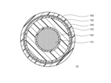
- the power cable 10 has, for example, a conductor 110, an inner semiconductive layer 120, an insulating layer 130, an outer semiconductive layer 140, a shielding layer 150, and a sheath 160.
- the conductor 110 is formed by twisting together a plurality of conductor core wires (conductive core wires) containing, for example, pure copper, a copper alloy, aluminum, an aluminum alloy, or the like.
- the internal semiconductive layer 120 is provided so as to cover the outer periphery of the conductor 110.
- the internal semiconductive layer 120 has semiconductivity and is configured to suppress electric field concentration on the surface side of the conductor 110.
- the internal semiconductive layer 120 contains, for example, at least one of an ethylene-based copolymer such as an ethylene-ethyl acrylate copolymer, an ethylene-methyl acrylate copolymer, an ethylene-butyl acrylate copolymer, and an ethylene-vinyl acetate copolymer, an olefin-based elastomer, the above-mentioned low crystalline resin, and the like, and conductive carbon black.
- an ethylene-based copolymer such as an ethylene-ethyl acrylate copolymer, an ethylene-methyl acrylate copolymer, an ethylene-butyl acrylate copolymer, and an ethylene-vinyl acetate copolymer, an
- the insulating layer 130 is provided so as to cover the outer periphery of the internal semiconductive layer 120.
- the insulating layer 130 is, for example, extrusion molded from a resin composition as described above.
- the insulating layer 130 has an inner peripheral surface facing the conductor 110 and an outer peripheral surface opposite to the inner peripheral surface.
- the elasticity of the insulating layer 130 varies in the thickness direction of the insulating layer 130.
- the insulating property of the insulating layer 130 is uniform in the thickness direction of the insulating layer 130. This point will be described in detail later.
- the insulating layer 130 has a predetermined phase structure by mixing a base polymer (A), a modified polymer (B), and a thermoplastic elastomer (C).
- the modified polymer (B) in the insulating layer 130, a structure in which the base polymer (A) and the modified polymer (B) are compatible with each other, or a sea-island structure in which the modified polymer (B) is finely dispersed in the base polymer (A) is formed.
- the "compatible structure” here means that, for example, when the phase structure is observed with a transmission electron microscope, no phase separation can be confirmed and each component is uniformly dispersed.
- the insulating layer 130 contains not only the base polymer (A) and modified polymer (B) but also the thermoplastic elastomer (C), a sea-island structure in which the thermoplastic elastomer (C) is finely dispersed is formed in the above-mentioned phase structure of the two-component system in which the insulating layer 130 contains the base polymer (A) and modified polymer (B).
- the polar groups in the modified polymer (B) can be uniformly dispersed in the insulating layer 130. This allows the space charge trapping effect to be obtained uniformly in the insulating layer 130.
- thermoplastic elastomer (C) can be uniformly dispersed in the insulating layer 130. This makes it possible to obtain a stable distribution of elasticity in the insulating layer 130 according to the difference in cooling rate in the thickness direction of the insulating layer 130.
- the insulating layer 130 is non-crosslinked, or even if the insulating layer 130 is crosslinked, the gel fraction (degree of crosslinking) is low.
- the crosslinking agent residue in the insulating layer 130 is, for example, less than 300 ppm.
- the insulating layer 130 is slightly crosslinked, for example, so that the decomposition residue of the crosslinking agent is less than 300 ppm. In this way, by making the insulating layer 130 non-crosslinked or with a low degree of crosslinking, recyclability can be improved.
- the outer semiconductive layer 140 is provided so as to cover the outer periphery of the insulating layer 130.
- the outer semiconductive layer 140 has semiconductivity and is configured to suppress electric field concentration between the insulating layer 130 and the shielding layer 150.
- the outer semiconductive layer 140 is configured of, for example, the same material as the inner semiconductive layer 120.
- the shielding layer 150 is provided so as to cover the outer periphery of the outer semiconductive layer 140.
- the shielding layer 150 is formed, for example, by winding a copper tape, or is formed as a wire shield in which a plurality of soft copper wires or the like are wound. Tape made of a material such as rubber-coated cloth may be wound on the inside or outside of the shielding layer 150.
- the sheath 160 is provided so as to cover the outer periphery of the shielding layer 150.
- the sheath 160 is made of, for example, polyvinyl chloride or polyethylene.
- the power cable 10 of this embodiment is an underwater cable or an underwater cable, it may have a metal waterproof layer such as an aluminum sheath or an iron wire armor outside the shielding layer 150.
- the power cable 10 of this embodiment may not have a water-proof layer outside the shielding layer 150, for example.
- the power cable 10 of this embodiment may be configured with a non-completely water-proof structure.
- the diameter of the conductor 110 is 5 mm or more and 60 mm or less
- the thickness of the inner semiconductive layer 120 is 0.5 mm or more and 3 mm or less
- the thickness of the insulating layer 130 is 3 mm or more and 35 mm or less
- the thickness of the outer semiconductive layer 140 is 0.5 mm or more and 3 mm or less
- the thickness of the shielding layer 150 is 0.1 mm or more and 5 mm or less
- the thickness of the sheath 160 is 1 mm or more.
- the DC voltage applied to the power cable 10 of this embodiment is, for example, 20 kV or more.
- the insulating layer 130 ensures the following cable characteristics.
- outer sample refers to a sheet taken from a position 0.3 mm from the outer peripheral surface of the insulating layer 130 toward the conductor 110 in the radial direction of the conductor 110.
- Inner sample refers to a sheet taken from a position 0.3 mm from the inner peripheral surface of the insulating layer 130 toward the outer peripheral surface of the insulating layer 130 in the radial direction of the conductor 110.
- the ratio of the storage modulus of the inner sample of the insulating layer 130 to the storage modulus of the outer sample of the insulating layer 130 (hereinafter also referred to as the "elastic modulus ratio”) is, for example, 1.1 or more and 2.5 or less.
- the "storage modulus” referred to here is measured by dynamic mechanical analysis (DMA) in accordance with JIS K7244-4:1999.
- Measurement mode Tensile mode Distortion: 0.08% Frequency: 10Hz Temperature range: 0°C to 200°C Heating rate: 10°C/min
- the "storage modulus of the outer sample” and the “storage modulus of the inner sample” in the above-mentioned elastic modulus ratio definition are values measured at 25°C by the dynamic viscoelasticity measurement.
- the thickness of each sample is 0.5 mm.
- the elastic modulus of the insulating layer 130 may, for example, gradually decrease from the inner peripheral surface of the insulating layer 130 toward the outer peripheral surface of the insulating layer 130 in the radial direction of the conductor 110. In this way, by suppressing a sudden change in the elasticity of the insulating layer 130, it is possible to suppress the occurrence of cracks in the insulating layer 130 due to differences in the elastic modulus.
- the storage modulus of the inner sample of the insulating layer 130 is, for example, 650 MPa or more and 900 MPa or less. By making the storage modulus of the inner sample 650 MPa or more, the rigidity of the power cable 10 can be ensured. On the other hand, by making the storage modulus of the inner sample 900 MPa or less, the decrease in flexibility of the power cable 10 can be suppressed.
- the storage modulus of the outer sample of the insulating layer 130 is, for example, 280 MPa or more and 670 MPa or less.
- the storage modulus of the outer sample 280 MPa or more it is possible to prevent the outer side of the insulating layer 130 from becoming excessively soft. This makes it possible to prevent the occurrence of cracks in the insulating layer 130 due to impacts when the power cable 10 is installed.
- the storage modulus of the outer sample 670 MPa or less it is possible to ensure the flexibility of the power cable 10.
- the space charge trapping effect of the modified polymer (B) can be uniformly obtained in the insulating layer 130.
- the insulating property of the insulating layer 130 is uniform in the thickness direction of the insulating layer 130.
- the ratio of the volume resistivity of the inner sample of the insulating layer 130 to the volume resistivity of the outer sample of the insulating layer 130 (hereinafter also referred to as the "volume resistivity ratio”) is, for example, 1.0 or more and 1.5 or less.
- volume resistivity of the outer sample and the “volume resistivity of the inner sample” mentioned here are measured under conditions of a temperature of 90°C and a DC electric field of 80 kV/mm.
- the volume resistivity ratio to 1.0 or more and 1.5 or less, the required sufficient insulation properties can be obtained for the entire insulating layer 130 of the power cable 10.
- the volume resistivity of the outer sample of insulating layer 130 and the volume resistivity of the inner sample of insulating layer 130 measured under conditions of a temperature of 90° C. and a DC electric field of 80 kV/mm may be, for example, 7.0 ⁇ 10 ⁇ cm or more, or 3.6 ⁇ 10 ⁇ cm or more, or 5.0 ⁇ 10 ⁇ cm or more, or 7.0 ⁇ 10 ⁇ cm or more.
- the thickness of each sample is 0.2 mm.
- the DC breakdown field strength of the outer sample of insulating layer 130 and the DC breakdown field strength of the inner sample of insulating layer 130 measured under a temperature condition of 90°C may be, for example, 160 kV/mm or more, or 200 kV/mm or more. In measuring the DC breakdown field strength, the thickness of each sample is 0.2 mm.
- the resin components including the base polymer (A), modified polymer (B), and thermoplastic elastomer (C) and other additives (antioxidants, etc.) are mixed (kneaded) in a mixer to form a mixture.
- mixers include open rolls, Banbury mixers, pressure kneaders, single-shaft mixers, and multi-shaft mixers.
- the mixture is granulated using an extruder.
- This forms a pellet-shaped resin composition that will form the insulating layer 130.
- the steps from mixing to granulation may be carried out in one go using a twin-screw extruder that has a high kneading effect.
- a conductor 110 is prepared by twisting together a plurality of conductor core wires.
- the insulating layer 130 is formed so as to cover the outer periphery of the conductor 110 using the above-mentioned resin composition.
- the cable core forming process S300 in this embodiment includes, for example, an extrusion process S320 and a cooling process S340.
- a three-layer co-extruder is used to simultaneously form the inner semiconductive layer 120, the insulating layer 130 and the outer semiconductive layer 140.
- the composition for the inner semiconductive layer is fed into extruder A, which is one of the three-layer co-extruders that forms the inner semiconductive layer 120.
- extruder B which forms insulating layer 130.
- the set temperature of extruder B is set to a temperature that is 10°C to 80°C higher than the melting point of base polymer (A).
- the set temperature is adjusted appropriately based on the linear speed and extrusion pressure.
- extruder C which forms the outer semiconductive layer 140, is fed a composition for the outer semiconductive layer, which contains the same materials as the resin composition for the inner semiconductive layer fed into extruder A.
- the extrusions from extruders A to C are guided to a common head, and the inner semiconductive layer 120, insulating layer 130, and outer semiconductive layer 140 are simultaneously extruded from the inside to the outside around the conductor 110. This forms the extrusion material that will become the cable core.
- the insulating layer 130 is cooled so that the ratio of the storage modulus of the inner sample of the insulating layer 130 to the storage modulus of the outer sample of the insulating layer 130 is 1.1 or more and 2.5 or less, and the ratio of the volume resistivity of the inner sample to the volume resistivity of the outer sample is 1.0 or more and 1.5 or less.
- the cable core is cooled so that a temperature difference is intentionally created between the inside and outside of the insulating layer 130.
- the cable cores formed in the extrusion process S320 are successively immersed in a water tank containing water (hereinafter, also referred to as cooling water) that has been cooled to a predetermined temperature by a chiller.
- cooling water water
- the cooling rate (temperature drop rate) at a temperature of 110°C is, for example, 30°C/min or more, or 75°C/min or more, or may be 100°C/min or more. This makes it possible to suppress excessive crystallization on the outside of the insulating layer 130. As a result, it is possible to reduce the elasticity of the outside of the insulating layer 130.
- the "cooling rate at a temperature of 110°C" here is calculated as the absolute value of the gradient of temperature against time at a temperature of 110°C.
- the cooling rate at the temperature of 110°C at the collection position of the outer sample of the insulating layer 130 may be, for example, 310°C/min or less. This makes it possible to suppress excessive variation in crystallinity in the thickness direction of the insulating layer 130. As a result, it is possible to suppress the occurrence of excessive elasticity differences in the thickness direction of the insulating layer 130.
- the temperature of the cooling water in the water tank is set to, for example, -50°C or higher and 50°C or lower. This allows the outside of the insulating layer 130 to be cooled at the above-mentioned cooling rate.
- the insulating layer 130 is cooled from the region close to the outer circumferential surface of the insulating layer 130 while the conductor 110 is electromagnetically heated.
- electromagnetic induction heating refers to heating the conductor 110 by heat generation due to eddy current loss generated in the conductor 110 by electromagnetic induction and heat generation in the conductor 110 due to hysteresis loss.
- the conductor 110 of the cable core immersed in the water tank can be heated in a non-contact manner by electromagnetic induction heating. This makes it possible to suppress cooling of the inside of the insulating layer 130 while rapidly cooling the outside of the insulating layer 130. In other words, the inside of the insulating layer 130 can be cooled slowly.
- the conductor 110 is heated by electromagnetic induction so that the temperature of the conductor 110 is between 80°C and 110°C.
- the elasticity of the inside of the insulating layer 130 can be made relatively high.
- the period during which the conductor 110 is electromagnetically heated to the above temperature may be shorter than the period during which the cable core is water-cooled, for example.
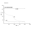
- the cooling step S340 as described above cools the insulating layer 130, for example, as shown in FIG. 2.
- the temperature of the outside of the insulating layer 130 drops rapidly from the temperature immediately after the extrusion step S320 to near the temperature of the cooling water. Meanwhile, the temperature of the inside of the insulating layer 130 close to the conductor 110 drops slowly to the temperature of the electromagnetically-induced heated conductor 110. After the electromagnetic induction heating of the conductor 110 is stopped, the temperature of the inside of the insulating layer 130 drops gradually to the temperature of the cooling water. In this way, the outside of the insulating layer 130 is cooled rapidly, while the inside of the insulating layer 130 is cooled slowly.
- the crystallization of the base polymer (A) can be suppressed outside the insulating layer 130, and the resin component can be solidified in a state close to amorphous. In other words, the degree of crystallization of the outside of the insulating layer 130 can be reduced.
- the base polymer (A) can be sufficiently crystallized inside the insulating layer 130. In other words, the degree of crystallization of the inside of the insulating layer 130 can be increased. As a result, the above-mentioned elasticity distribution can be obtained in the thickness direction of the insulating layer 130.
- a cable core is formed that is composed of the conductor 110, the inner semiconductive layer 120, the insulating layer 130 and the outer semiconductive layer 140.
- a shielding layer 150 is formed on the outside of the outer semiconductive layer 140, for example by wrapping copper tape around it.
- the polar groups in modified polymer (B) can be uniformly dispersed in insulating layer 130.
- This allows the space charge trapping effect of modified polymer (B) to be obtained uniformly in insulating layer 130.
- the insulating properties of insulating layer 130 can be made uniform in the thickness direction of insulating layer 130.
- the ratio of the storage modulus of the inner sample of the insulating layer 130 to the storage modulus of the outer sample of the insulating layer 130 can be set to 1.1 or more and 2.5 or less.
- the outside of the insulating layer 130 can be made relatively soft while the inside of the insulating layer 130 can be made relatively hard.
- the flexibility of the power cable 10 can be improved. For example, excessive restrictions on the reel diameter when winding the power cable 10 around the reel can be avoided.
- the inside of the insulating layer 130 relatively hard the rigidity of the power cable 10 can be ensured. In this way, it is possible to achieve both the flexibility of the insulating layer 130 and the strength of the insulating layer 130.
- the elastic modulus ratio to 2.5 or less, it is possible to suppress the occurrence of voids due to stress differences within the insulating layer 130. This makes it possible to suppress a decrease in the dielectric breakdown strength (e.g., DC breakdown field strength) of the insulating layer 130.
- the polar groups in the modified polymer (B) that traps space charges are uniformly dispersed in the insulating layer 130 at a predetermined content, so that the ratio of the volume resistivity of the inner sample of the insulating layer 130 to the volume resistivity of the outer sample of the insulating layer 130 can be set to 1.0 or more and 1.5 or less.
- the insulating layer 130 of the power cable 10 as a whole can have the required sufficient insulating properties.
- the insulating properties of the insulating layer 130 can be made uniform in the thickness direction of the insulating layer 130 while obtaining a desired distribution of elasticity in the thickness direction of the insulating layer 130. Therefore, even if the power cable 10 of this embodiment is applied to high-voltage applications, it is possible to stably achieve both the flexibility of the insulating layer 130 and the insulating properties of the insulating layer 130.
- the power cable 10 may have a simple water-shielding layer.
- the simple water-shielding layer is made of, for example, a metal laminate tape.
- the metal laminate tape has, for example, a metal layer made of aluminum or copper, and an adhesive layer provided on one or both sides of the metal layer.
- the metal laminate tape is, for example, wrapped vertically around the outer periphery of the cable core (outer periphery than the outer semiconductive layer).
- the water-shielding layer may be provided outside the shielding layer, or may also serve as the shielding layer. With such a configuration, the cost of the power cable 10 can be reduced.
- the power cable 10 is configured to be laid on land, underwater, or on the bottom of the water, but the present disclosure is not limited to this case.
- the power cable 10 may be configured as a so-called overhead electric wire (overhead insulated electric wire).
- each layer was extruded one at a time.
- the extrudates from extruders A to C were guided to a common head, and the internal semiconductive layer, the insulating layer, and the external semiconductive layer were simultaneously extruded from the inside to the outside around the conductor. At this time, the thicknesses of the internal semiconductive layer, the insulating layer, and the external semiconductive layer were set to 0.5 mm, 9 mm, and 0.5 mm, respectively. After the extrusion process, the extruded material was cooled by a cooling method corresponding to each sample. As a result, power cables of samples A1 to A8 and B1 to B9 were manufactured.
- Modified Polymer (B) Maleic anhydride modified polypropylene (MAH-PP): Amount of maleic anhydride modification: 5% by mass, Melting point: 160°C Storage modulus of the single substance at 25°C measured by dynamic viscoelasticity measurement: 1300 MPa
- Ethylene propylene rubber Ethylene unit content: 25% by mass, Melting point: None, Heat of fusion: None Storage modulus of the single substance measured by dynamic viscoelasticity measurement at 25°C: 80 MPa
- the temperature of the water bath was adjusted within the range of -50°C or higher and 50°C or lower, so that the cooling rate at a temperature of 110°C on the outside of the insulating layer was set to 40°C/min to 300°C/min.
- the conductor was heated by electromagnetic induction so that its temperature reached 110°C, while the insulating layer was cooled starting from the area close to the outer periphery of the insulating layer.
- Samples B1 to B4 were prepared in the same manner as Samples A1 to A4, respectively, except that slow cooling was carried out in the cooling step as follows.
- Samples B5 to B8 were prepared in the same manner as sample A3, except that the contents of the modified polymer (B) and the thermoplastic elastomer (C) were different from those of sample A3.
- Sample B9 was prepared in the same manner as Sample A3, except that in the cooling process, the temperature of the water bath was adjusted to -25°C, so that the cooling rate at the insulating layer temperature of 110°C was 312°C/min.
- the insulation layer of each of the power cables of samples A1 to A8 and B1 to B9 was thinly sliced in the circumferential direction.
- an outer sample of the insulation layer was taken from a position 0.3 mm from the outer peripheral surface of the insulation layer toward the conductor.
- An inner sample of the insulation layer was taken from a position 0.3 mm from the inner peripheral surface of the insulation layer toward the outer peripheral surface.
- the size of each sample in the dynamic viscoelasticity measurement was 5 mm long, 42 mm wide, and 0.5 mm thick.
- the size of each sample in the volume resistivity and DC breakdown field strength measurement was 50 mm long, 50 mm wide, and 0.2 mm thick.
- the storage modulus of the insulating layer in each sample was measured by dynamic mechanical analysis (DMA) in accordance with JIS K7244-4:1999 under the following conditions.
- Measuring device DVA-200 manufactured by IT Measurement and Control Co., Ltd.
- Measurement mode Tensile mode Distortion: 0.08% Frequency: 10Hz
- the storage modulus of the outer sample and the elastic modulus of the inner sample were measured at 25°C using the above-mentioned DMA.
- the DC breakdown field strength of the insulating layer in each sample was measured as follows. Specifically, similar to the measurement of the volume resistivity, a flat electrode having a diameter of 25 mm was placed on the first surface of the sheet as the outer sample or the inner sample and on the second surface opposite to the first surface. After the electrodes were placed, the sheet was immersed in silicone oil at a temperature of 90° C. In this state, the applied voltage was increased at a rate of 4 kV/min. Thereafter, the DC breakdown field strength of the sheet was measured when the sheet reached dielectric breakdown. In both the outer sample and the inner sample, the case where the DC breakdown field strength was 160 kV/mm or more was evaluated as A (good). On the other hand, the case where the DC breakdown field strength was less than 160 kV/mm in at least one of the outer sample and the inner sample was evaluated as B (bad).
- the cooling rate at the outer sample collection position increased.
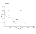
- the cable core was water-cooled when the temperature had already dropped to around 100°C at both the outer sample collection position and the inner sample collection position. As a result, the temperature difference between these did not increase.
- sample A3 In contrast, as shown in Fig. 2, in sample A3, the cable core was water-cooled immediately after the extrusion process. This resulted in a rapid drop in temperature at the outer sample extraction position. The cooling rate at the outer sample extraction position at a temperature of 110°C was 150°C/min.
- the conductor was electromagnetically heated so that its temperature reached 110°C. This caused the temperature to slowly drop at the location where the inner sample was taken. After that, the electromagnetic induction heating was stopped, and the temperature at the location where the inner sample was taken also began to drop to below 100°C due to water cooling of the cable core. However, the temperature at the location where the inner sample was taken had already dropped to around 110°C, and the temperature at the location where the inner sample was taken was therefore dropping slowly.
- samples B1 to B4 the degree of crystallization of the insulating layer was high and uniform in the thickness direction of the insulating layer due to the slow cooling of the insulating layer. For this reason, it is believed that the elasticity of the insulating layer in samples B1 to B4 was also uniform in the thickness direction of the insulating layer.
- sample B5 In sample B5, the outer side of the insulating layer was quenched like sample A3, but the modified polymer (B) was not added to the insulating layer.
- sample B5 the ratio of the volume resistivity of the inner sample to the volume resistivity of the outer sample was greater than 1.5.
- the DC breakdown field strength was less than 160 kV/mm.
- sample B5 the rapid cooling of the insulating layer caused a distribution (variation) in the degree of crystallinity in the thickness direction of the insulating layer. Furthermore, because modified polymer (B) was not added to the insulating layer, the space charge trapping effect of modified polymer (B) was not obtained. For this reason, it is believed that in sample B5, the insulating properties of the insulating layer were reduced and varied in the thickness direction of the insulating layer.
- sample B6 In sample B6, the outer side of the insulating layer was quenched like sample A3, but the content of the modified polymer (B) in the insulating layer was more than 10 parts by mass.
- sample B6 the ratio of the volume resistivity of the inner sample to the volume resistivity of the outer sample exceeded 1.5.
- the DC breakdown field strength was less than 160 kV/mm in both the outer and inner samples of sample B6.
- sample B6 the content of modified polymer (B) in the insulating layer exceeded 10 parts by mass, which reduced the moldability of the insulating layer. This reduced moldability led to a reduction in the insulating properties of the insulating layer. As a result, it is believed that in sample B6, the insulating properties of the insulating layer were reduced and varied in the thickness direction of the insulating layer.
- sample B7 In sample B7, the outer side of the insulating layer was quenched like sample A3, but the content of the thermoplastic elastomer (C) in the insulating layer was less than 10 parts by mass.
- the storage modulus of the inner sample was particularly high in sample B7.
- the ratio of the storage modulus of the inner sample to the storage modulus of the outer sample exceeded 2.5.
- the DC breakdown field strength of the outer sample of sample B7 was less than 160 kV/mm.
- thermoplastic elastomer (C) in the insulating layer was less than 10 parts by mass, so the thermoplastic elastomer (C) did not provide sufficient flexibility.
- the elasticity of the insulating layer varied greatly in the thickness direction of the insulating layer.
- voids occurred due to stress differences within the insulating layer.
- the dielectric breakdown strength of sample B7 decreased due to the occurrence of voids in the insulating layer.
- sample B8 In sample B8, the outer side of the insulating layer was quenched like sample A3, but the content of the thermoplastic elastomer (C) in the insulating layer was more than 45 parts by mass.
- sample B8 the volume resistivity was low overall, and the ratio of the volume resistivity of the inner sample to the volume resistivity of the outer sample exceeded 1.5.
- the DC breakdown field strength was less than 160 kV/mm in both the outer and inner samples of sample B8.
- sample B8 the content of amorphous thermoplastic elastomer (C) in the insulating layer exceeded 45 parts by mass, which reduced the insulating properties required of polypropylene with a high melting point as the base polymer (A). As a result, it is believed that in sample B8, the insulating properties of the insulating layer were reduced and varied in the thickness direction of the insulating layer.
- sample B9 In sample B9, the cooling rate at the temperature of 110° C. was more than 310° C./min at the outer sample collection position of the insulating layer.
- sample B9 the ratio of the storage modulus of the inner sample to the storage modulus of the outer sample was greater than 2.5.
- the DC breakdown field strength was less than 160 kV/mm.
- sample B9 the cooling rate of the outside of the insulating layer was too fast, which caused excessive variation in the degree of crystallinity in the thickness direction of the insulating layer. This caused the elasticity of the insulating layer to vary greatly in the thickness direction of the insulating layer. Furthermore, voids were generated due to stress differences within the insulating layer. As a result, it is believed that the dielectric breakdown strength of sample B9 was reduced due to the generation of voids in the insulating layer.
- samples A1 to A8 In contrast, in samples A1 to A8, the modified polymer (B) and the thermoplastic elastomer (C) were added to the insulating layer.
- the content of the modified polymer (B) in the insulating layer was 1 part by mass or more and 10 parts by mass or less
- the content of the thermoplastic elastomer (C) in the resin composition was 10 parts by mass or more and 45 parts by mass or less.
- the outside of the insulating layer was quenched as described above. At this time, the cooling rate at a temperature of 110°C at the sampling position of the outer sample of the insulating layer was 30°C/min or more and 310°C/min or less.
- the ratio of the storage modulus of the inner sample to the storage modulus of the outer sample was 1.1 or more and 2.5 or less.
- the ratio of the volume resistivity of the inner sample to the volume resistivity of the outer sample was 1.0 or more and 1.5 or less.
- the DC breakdown field strength was 160 kV/mm or more.
- Each of the volume resistivity of the outer sample and the volume resistivity of the inner sample is 7.0 ⁇ 10 ⁇ cm or more;
- the volume resistivity of the outer sample and the volume resistivity of the inner sample are measured under conditions of a temperature of 90°C and a DC electric field of 80 kV/mm.
Landscapes
- Physics & Mathematics (AREA)
- Spectroscopy & Molecular Physics (AREA)
- Engineering & Computer Science (AREA)
- Manufacturing & Machinery (AREA)
- Chemical & Material Sciences (AREA)
- Health & Medical Sciences (AREA)
- Chemical Kinetics & Catalysis (AREA)
- Medicinal Chemistry (AREA)
- Polymers & Plastics (AREA)
- Organic Chemistry (AREA)
- Organic Insulating Materials (AREA)
- Compositions Of Macromolecular Compounds (AREA)
Abstract
Description
電力ケーブルの導体を覆うように設けられ、前記導体に対向する内周面および前記内周面と反対の外周面を有する絶縁層を構成する樹脂組成物であって、
プロピレン単位を含むベースポリマと、
プロピレン単位を含み不飽和有機酸およびその誘導体から選択される少なくとも1つにより変性された変性ポリマと、
熱可塑性エラストマと、
を含み、
前記樹脂組成物は、
前記絶縁層の外側試料の貯蔵弾性率に対する、前記絶縁層の内側試料の貯蔵弾性率の比率が1.1以上2.5以下となり、且つ、
前記外側試料の体積抵抗率に対する、前記内側試料の体積抵抗率の比率は、1.0以上1.5以下となるように構成されている、
ここで、
前記絶縁層の前記外側試料は、前記外周面から前記導体に向けて0.3mmの位置から採取され、
前記絶縁層の前記内側試料は、前記内周面から前記外周面に向けて0.3mmの位置から採取され、
前記外側試料の前記貯蔵弾性率および前記内側試料の前記貯蔵弾性率は、動的粘弾性測定により25℃で測定され、
前記外側試料の前記体積抵抗率および前記内側試料の前記体積抵抗率は、温度90℃および直流電界80kV/mmの条件下において測定される
樹脂組成物が提供される。
本発明者等は、絶縁層を構成する樹脂成分としてポリプロピレンに着目し、電力ケーブルの特性向上のため、鋭意検討を行った。
本開示によれば、絶縁層の柔軟性、強度および絶縁性を向上させることができる。
<発明者等の得た知見>
まず、発明者等の得た知見について概略を説明する。
次に、本開示の実施態様を列記して説明する。
電力ケーブルの導体を覆うように設けられ、前記導体に対向する内周面および前記内周面と反対の外周面を有する絶縁層を構成する樹脂組成物であって、
プロピレン単位を含むベースポリマと、
プロピレン単位を含み不飽和有機酸およびその誘導体から選択される少なくとも1つにより変性された変性ポリマと、
熱可塑性エラストマと、
を含み、
前記樹脂組成物は、
前記絶縁層の外側試料の貯蔵弾性率に対する、前記絶縁層の内側試料の貯蔵弾性率の比率が1.1以上2.5以下となり、且つ、
前記外側試料の体積抵抗率に対する、前記内側試料の体積抵抗率の比率は、1.0以上1.5以下となるように構成されている、
ここで、
前記絶縁層の前記外側試料は、前記外周面から前記導体に向けて0.3mmの位置から採取され、
前記絶縁層の前記内側試料は、前記内周面から前記外周面に向けて0.3mmの位置から採取され、
前記外側試料の前記貯蔵弾性率および前記内側試料の前記貯蔵弾性率は、動的粘弾性測定により25℃で測定され、
前記外側試料の前記体積抵抗率および前記内側試料の前記体積抵抗率は、温度90℃および直流電界80kV/mmの条件下において測定される。
この構成によれば、絶縁層の柔軟性、強度および絶縁性を向上させることができる。
導体と、
前記導体の外周を覆うように設けられ、前記導体に対向する内周面および前記内周面と反対の外周面を有する絶縁層と、
を備え、
前記絶縁層は、
プロピレン単位を含むベースポリマと、
プロピレン単位を含み不飽和有機酸およびその誘導体から選択される少なくとも1つにより変性された変性ポリマと、
熱可塑性エラストマと、
を含み、
前記絶縁層の外側試料の貯蔵弾性率に対する、前記絶縁層の内側試料の貯蔵弾性率の比率は、1.1以上2.5以下であり、
前記外側試料の体積抵抗率に対する、前記内側試料の体積抵抗率の比率は、1.0以上1.5以下である、
ここで、
前記絶縁層の前記外側試料は、前記外周面から前記導体に向けて0.3mmの位置から採取され、
前記絶縁層の前記内側試料は、前記内周面から前記外周面に向けて0.3mmの位置から採取され、
前記外側試料の前記貯蔵弾性率および前記内側試料の前記貯蔵弾性率は、動的粘弾性測定により25℃で測定され、
前記外側試料の前記体積抵抗率および前記内側試料の前記体積抵抗率は、温度90℃および直流電界80kV/mmの条件下において測定される。
この構成によれば、絶縁層の柔軟性、強度および絶縁性を向上させることができる。
前記絶縁層中の前記ベースポリマ、前記変性ポリマおよび前記熱可塑性エラストマの合計の含有量を100質量部としたときに、
前記絶縁層中の前記変性ポリマの含有量は、1質量部以上10質量部以下であり、
前記絶縁層中の前記熱可塑性エラストマの含有量は、10質量部以上45質量部以下である。
この構成によれば、絶縁層の厚さ方向において、弾性の所望の分布と、絶縁性の均一性と、を安定的に両立することができる。
前記熱可塑性エラストマは、スチレン系エラストマを含む。
この構成によれば、柔軟性を有する熱可塑性エラストマ(C)の分子構造内において、短鎖分岐を容易に取り入れることができる。その結果、ベースポリマ(A)と熱可塑性エラストマ(C)との相溶性を良くすることができる。
前記熱可塑性エラストマは、オレフィン系エラストマを含む。
この構成によれば、柔軟性を有する熱可塑性エラストマ(C)の分子構造内において、短鎖分岐を容易に取り入れることができる。その結果、ベースポリマ(A)と熱可塑性エラストマ(C)との相溶性を良くすることができる。
前記絶縁層の前記内側試料の前記貯蔵弾性率は、650MPa以上900MPa以下であり、
前記絶縁層の前記外側試料の前記貯蔵弾性率は、280MPa以上670MPa以下である。
この構成によれば、電力ケーブル10の剛性および可撓性を両立することができる。
前記絶縁層の厚さは、3mm以上である。
この構成によれば、電力ケーブルを高電圧の用途に適用したとしても、絶縁層の可撓性および絶縁層の絶縁性を安定的に両立することが可能となる。
樹脂組成物を準備する工程と、
前記樹脂組成物により、導体の外周を覆うように絶縁層を形成し、前記絶縁層において、前記導体に対向する内周面と、前記内周面と対向する外周面とを形成する工程と、
を備え、
前記樹脂組成物を準備する工程では、
前記樹脂組成物として、
プロピレン単位を含むベースポリマと、
プロピレン単位を含み不飽和有機酸およびその誘導体から選択される少なくとも1つにより変性された変性ポリマと、
熱可塑性エラストマと、
を含む組成物を準備し、
前記絶縁層を形成する工程は、
前記導体の前記外周に前記絶縁層を押出成形する工程と、
前記絶縁層の外側試料の貯蔵弾性率に対する、前記絶縁層の内側試料の貯蔵弾性率の比率が1.1以上2.5以下となり、且つ、前記外側試料の体積抵抗率に対する、前記内側試料の体積抵抗率の比率は、1.0以上1.5以下となるように、前記絶縁層を冷却する工程と、
を有する、
ここで、
前記絶縁層の前記外側試料は、前記外周面から前記導体に向けて0.3mmの位置から採取され、
前記絶縁層の前記内側試料は、前記内周面から前記外周面に向けて0.3mmの位置から採取され、
前記外側試料の前記貯蔵弾性率および前記内側試料の前記貯蔵弾性率は、動的粘弾性測定により25℃で測定され、
前記外側試料の前記体積抵抗率および前記内側試料の前記体積抵抗率は、温度90℃および直流電界80kV/mmの条件下において測定される。
この構成によれば、絶縁層の柔軟性、強度および絶縁性を向上させることができる。
前記絶縁層を冷却する工程では、
前記絶縁層を押出成形する工程の直後から少なくとも一部の期間において、前記導体を電磁誘導加熱しながら、前記絶縁層の前記外周面に近い領域から前記絶縁層を冷却する。
この構成によれば、絶縁層の内側を徐冷することができる。
次に、本開示の一実施形態を、以下に図面を参照しつつ説明する。なお、本開示はこれらの例示に限定されるものではなく、請求の範囲によって示され、請求の範囲と均等の意味および範囲内でのすべての変更が含まれることが意図される。
(1)樹脂組成物
本実施形態の樹脂組成物は、後述する電力ケーブル10の絶縁層130を構成する材料である。樹脂組成物は、例えば、ベースポリマ(A)と、変性ポリマ(B)と、熱可塑性エラストマ(C)と、その他の添加剤と、を有している。
ベースポリマ(ベース樹脂)(A)とは、樹脂組成物の主成分を構成する樹脂成分のことをいう。「主成分」とは、最も含有量が多い成分のことを意味する。
変性ポリマ(B)は、プロピレン単位を主鎖として含み、不飽和有機酸並びにその誘導体から選択される少なくとも1つにより変性された樹脂である。
熱可塑性エラストマ(C)は、プロピレン単位を有するベースポリマ(A)と比較して低い結晶性を有している。熱可塑性エラストマ(C)により、ベースポリマ(A)の過剰な結晶成長を抑制し、絶縁層130に柔軟性を付与することができる。
熱可塑性エラストマ(C)は、例えば、スチレン系エラストマを含んでいてもよい。これにより、柔軟性を有する熱可塑性エラストマ(C)の分子構造内において、短鎖分岐を容易に取り入れることができる。その結果、ベースポリマ(A)と熱可塑性エラストマ(C)との相溶性を良くすることができる。
熱可塑性エラストマ(C)は、例えば、オレフィン系エラストマを含んでいてもよい。これにより、柔軟性を有する熱可塑性エラストマ(C)の分子構造内において、短鎖分岐を容易に取り入れることができる。その結果、ベースポリマ(A)と熱可塑性エラストマ(C)との相溶性を良くすることができる。
本実施形態では、熱可塑性エラストマ(C)単体としての貯蔵弾性率は、例えば、20MPa以上500MPa以下である。ここでいう「熱可塑性エラストマ(C)単体としての貯蔵弾性率」の測定方法および測定条件は、後述する絶縁層の貯蔵弾性率と同様である。
変性ポリマ(B)および熱可塑性エラストマ(C)の含有量について説明する。ここで、ベースポリマ(A)、変性ポリマ(B)および熱可塑性エラストマ(C)により構成される樹脂成分の合計の含有量を100質量部とする。樹脂成分のうち、変性ポリマ(B)および熱可塑性エラストマ(C)以外の残部は、ベースポリマ(A)である。
本実施形態では、樹脂組成物が変性ポリマ(B)を含むことで、上述のように、変性ポリマ(B)による空間電荷のトラップ効果を樹脂組成物中で均一に得ることができる。これにより、無機充填剤を添加せずとも、高い絶縁性を安定して得ることができる。そのため、本実施形態では、樹脂組成物は無機充填剤を含まなくてもよい。
MV=Σ(Vidi)/ΣVi
なお、体積平均粒径の測定には、動的光散乱式粒子径・粒度分布測定装置が用いられる。
本実施形態では、絶縁層130を構成する樹脂成分は、リサイクルの観点から、非架橋であってもよい。この場合、樹脂組成物は、架橋剤を含まなくてもよい。
樹脂組成物は、必要に応じて、その他の添加剤を含んでいてもよい。その他の添加剤としては、酸化防止剤、滑剤および着色剤が挙げられる。
次に、図1を参照し、本実施形態の電力ケーブルについて説明する。
導体110は、例えば、純銅、銅合金、アルミニウム、またはアルミニウム合金等を含む複数の導体芯線(導電芯線)を撚り合わせることにより構成されている。
内部半導電層120は、導体110の外周を覆うように設けられている。また、内部半導電層120は、半導電性を有し、導体110の表面側における電界集中を抑制するよう構成されている。内部半導電層120は、例えば、エチレン-エチルアクリレート共重合体、エチレン-メチルアクリレート共重合体、エチレン-ブチルアクリレート共重合体、およびエチレン-酢酸ビニル共重合体等のエチレン系共重合体、オレフィン系エラストマ、上述の低結晶性樹脂などのうち少なくともいずれかと、導電性のカーボンブラックと、を含んでいる。
絶縁層130は、内部半導電層120の外周を覆うように設けられている。絶縁層130は、例えば、上述のように、樹脂組成物により押出成形されている。絶縁層130は、導体110に対向する内周面と、内周面と反対の外周面と、を有している。
外部半導電層140は、絶縁層130の外周を覆うように設けられている。また、外部半導電層140は、半導電性を有し、絶縁層130と遮蔽層150との間における電界集中を抑制するよう構成されている。外部半導電層140は、例えば、内部半導電層120と同様の材料により構成されている。
遮蔽層150は、外部半導電層140の外周を覆うように設けられている。遮蔽層150は、例えば、銅テープを巻回することにより構成されるか、或いは、複数の軟銅線等を巻回したワイヤシールドとして構成されている。遮蔽層150の内側や外側に、ゴム引き布等を素材としたテープが巻回されていてもよい。
シース160は、遮蔽層150の外周を覆うように設けられている。シース160は、例えば、ポリ塩化ビニルまたはポリエチレンにより構成されている。
電力ケーブル10における具体的な各寸法としては、特に限定されるものではないが、例えば、導体110の直径は5mm以上60mm以下であり、内部半導電層120の厚さは0.5mm以上3mm以下であり、絶縁層130の厚さは3mm以上35mm以下であり、外部半導電層140の厚さは0.5mm以上3mm以下であり、遮蔽層150の厚さは0.1mm以上5mm以下であり、シース160の厚さは1mm以上である。本実施形態の電力ケーブル10に適用される直流電圧は、例えば20kV以上である。
本実施形態では、絶縁層130では、以下のケーブル諸特性が確保されている。
本実施形態では、絶縁層130の押出工程後に後述の冷却工程を実施することで、絶縁層130の弾性が絶縁層130の厚さ方向に異なっている。
測定モード:引張モード
歪み:0.08%
周波数:10Hz
温度範囲:0℃以上200℃以下
昇温速度:10℃/min
本実施形態では、絶縁層130が変性ポリマ(B)を含むことで、変性ポリマ(B)による空間電荷のトラップ効果を絶縁層130中で均一に得ることができる。その結果、絶縁層130の絶縁性は、絶縁層130の厚さ方向に均一になっている。
次に、本実施形態の電力ケーブルの製造方法について説明する。以下、ステップを「S」と略す。
まず、本実施形態の樹脂組成物を準備する。
一方で、複数の導体芯線を撚り合わせることにより形成された導体110を準備する。
樹脂組成物準備工程S100および導体準備工程S200が完了したら、ケーブルコア形成工程S300において、上述の樹脂組成物を用い、導体110の外周を被覆するように絶縁層130を形成する。
本実施形態では、例えば、3層同時押出機を用いて、内部半導電層120、絶縁層130および外部半導電層140を同時に形成する。
押出工程S320が完了したら、上述の押出材を冷却する。
ケーブルコアを形成したら、外部半導電層140の外側に、例えば銅テープを巻回することにより遮蔽層150を形成する。
遮蔽層150を形成したら、押出機に塩化ビニルを投入して押出すことにより、遮蔽層150の外周に、シース160を形成する。
本実施形態によれば、以下に示す1つ又は複数の効果を奏する。
以上、本開示の実施形態について具体的に説明したが、本開示は上述の実施形態に限定されるものではなく、その要旨を逸脱しない範囲において種々変更可能である。
後述の表1および表2に示すように、サンプルA1~A8、B1~B9のそれぞれにおいて、樹脂組成物をバンバリミキサによって混合し、押出機によりペレット状に造粒した。次に、直径が14mmの希薄銅合金製の導体芯線を撚り合せることにより形成された断面積2500mm2の導体を準備した。導体を準備したら、エチレン-エチルアクリレート共重合体を含む内部半導電層用樹脂組成物と、上述の樹脂組成物と、内部半導電層用樹脂組成物と同様の材料からなる外部半導電層用樹脂組成物と、をそれぞれ押出機A~Cに投入した。押出機A~Cからのそれぞれの押出物をコモンヘッドに導き、導体の外周に、内側から外側に向けて、内部半導電層、絶縁層および外部半導電層を同時に押出した。このとき、内部半導電層、絶縁層および外部半導電層の厚さを、それぞれ、0.5mm、9mm、0.5mmとした。押出工程後、各サンプルに応じた冷却方法により押出材を冷却した。その結果、サンプルA1~A8、B1~B9のそれぞれの電力ケーブルを製造した。
(ベースポリマ(A))
ランダムポリプロピレン(r-PP):
立体規則性:アイソタクチック
密度:0.9g/ml、
融点:150℃、
融解熱量:60J/g
動的粘弾性測定により測定した25℃での単体の貯蔵弾性率:1150MPa
無水マレイン酸変性ポリプロピレン(MAH-PP):
無水マレイン酸変性量:5質量%、
融点:160℃
動的粘弾性測定により測定した25℃での単体の貯蔵弾性率:1300MPa
スチレンエチレンブチレンスチレンブロック共重合体(SEBS):
スチレン単位含有量:25質量%、
融点:なし
動的粘弾性測定により測定した25℃での単体の貯蔵弾性率:120MPa
エチレン単位含有量:25質量%、
融点:なし、
融解熱量:なし
動的粘弾性測定により測定した25℃での単体の貯蔵弾性率:80MPa
押出温度:190℃
サンプルA1~A8の冷却工程では、以下のように、急冷を行った。チラーにより冷却された冷却水を有する水槽内に、押出工程により形成されたケーブルコアを順次浸漬させた。これにより、絶縁層の外周面に近い領域から絶縁層を急冷した。
サンプルB1~B4は、冷却工程において以下の徐冷を行った点を除いて、それぞれ、サンプルA1~A4と同様に作製した。
サンプルB1~B4の冷却工程では、まず、押出工程により形成されたケーブルコアを、700秒の間、空冷した。その後、チラーにより冷却された冷却水を有する水槽内に、押出工程により形成されたケーブルコアを順次浸漬させた。これにより、絶縁層の外周面に近い領域から絶縁層を冷却した。このときの水槽の温度は、25℃とした。
サンプルB5~B8は、変性ポリマ(B)の含有量および熱可塑性エラストマ(C)の含有量がサンプルA3のそれらと異なる点を除いて、サンプルA3と同様に作製した。
サンプルB9は、冷却工程において、水槽の温度を-25℃に調整することで、絶縁層の温度110℃での冷却速度を312℃/minとした点を除いて、サンプルA3と同様に作製した。
(温度推移)
サンプルA3およびサンプルB1のそれぞれにおいて、以下のようにして冷却工程の温度推移を測定した。各サンプルの押出工程直後において、絶縁層の外側試料の採取位置と、絶縁層の内側試料の採取位置に、それぞれ、熱電対を配置した(突き刺した)。その後、冷却工程において、各位置での温度推移を熱電対により測定した。測定の結果、外側試料の採取位置において、温度110℃での冷却速度を求めた。
冷却工程後、サンプルA1~A8、B1~B9のそれぞれの電力ケーブルの絶縁層を周方向に沿って薄くスライスした。これにより、絶縁層の外側試料を、絶縁層の外周面から導体に向けて0.3mmの位置から採取した。絶縁層の内側試料を、絶縁層の内周面から外周面に向けて0.3mmの位置から採取した。動的粘弾性測定における各試料のサイズは、縦5mm、横42mm、厚さ0.5mmとした。体積抵抗率および直流破壊電界強度の測定における各試料のサイズは、縦50mm、横50mm、厚さ0.2mmとした。
各サンプルにおける絶縁層の貯蔵弾性率を、JIS K7244-4:1999に準拠して、動的粘弾性測定(DMA)により、以下の条件下で測定した。
測定装置:アイティー計測制御株式会社製DVA-200
測定モード:引張モード
歪み:0.08%
周波数:10Hz
温度範囲:0℃以上200℃以下
昇温速度:10℃/min
各サンプルにおける絶縁層の体積抵抗率は、以下のようにして測定した。まず、外側試料または内側試料としてのシートの第1面と、第1面と反対の第2面とにおいて、直径25mmの平板電極を配置した。電極を配置したら、シートを温度90℃のシリコーンオイル中に浸漬させた。この状態で、80kV/mmの直流電界をシートに印加した。これにより、体積抵抗率を測定した。
各サンプルにおける絶縁層の直流破壊電界強度は、以下のようにして測定した。具体的には、体積抵抗率の測定と同様に、外側試料または内側試料としてのシートの第1面と、第1面と反対の第2面とにおいて、直径25mmの平板電極を配置した。電極を配置したら、シートを温度90℃のシリコーンオイル中に浸漬させた。この状態で、4kV/minの速度で印加電圧を上昇させた。その後、シートが絶縁破壊に至ったときのシートの直流破壊電界強度を測定した。外側試料および内側試料の両方において、直流破壊電界強度が160kV/mm以上である場合をA(良好)とした。一方で、外側試料および内側試料の少なくともいずれかにおいて、直流破壊電界強度が160kV/mm未満である場合をB(不良)として評価した。
図2、図3、以下の表1および表2を参照し、各サンプルの評価を行った結果を説明する。各表の「冷却方法」において、「徐冷」とは、サンプルB1と同様の徐冷を実施したことを意味している。「急冷」とは、サンプルA3と同様の急冷を実施したことを意味している。

(サンプルB1)
図3に示すように、サンプルB1の押出工程後の空冷を実施した期間では、外側試料の採取位置および内側試料の採取位置の両方において、温度が緩やかに下がっていた。外側試料の採取位置において、温度110℃での冷却速度は、2.5℃/minであった。
これに対し、図2に示すように、サンプルA3では、押出工程の直後からケーブルコアを水冷した。これにより、外側試料の採取位置において、温度が急激に下がっていた。外側試料の採取位置において、温度110℃での冷却速度は、150℃/minであった。
(サンプルB1~B4)
サンプルB1~B4では、ベースポリマ(A)、変性ポリマ(B)および熱可塑性エラストマ(C)の含有量を、それぞれ、サンプルA1~A4と同様としたが、絶縁層を徐冷した。
サンプルB5では、サンプルA3と同様に絶縁層の外側を急冷したが、絶縁層に変性ポリマ(B)を添加しなかった。
サンプルB6では、サンプルA3と同様に絶縁層の外側を急冷したが、絶縁層中の変性ポリマ(B)の含有量が10質量部超であった。
サンプルB7では、サンプルA3と同様に絶縁層の外側を急冷したが、絶縁層中の熱可塑性エラストマ(C)の含有量が10質量部未満であった。
サンプルB8では、サンプルA3と同様に絶縁層の外側を急冷したが、絶縁層中の熱可塑性エラストマ(C)の含有量が45質量部超であった。
サンプルB9では、絶縁層の外側試料の採取位置において、温度110℃での冷却速度は、310℃/min超であった。
これに対し、サンプルA1~A8では、絶縁層に変性ポリマ(B)および熱可塑性エラストマ(C)を添加した。サンプルA1~A8では、絶縁層中の変性ポリマ(B)の含有量が1質量部以上10質量部以下であり、樹脂組成物中の熱可塑性エラストマ(C)の含有量が10質量部以上45質量部以下であった。さらに、サンプルA1~A8では、上述のように、絶縁層の外側を急冷した。このとき、絶縁層の外側試料の採取位置において、温度110℃での冷却速度は、30℃/min以上310℃/min以下であった。
以下、本開示の態様を付記する。下記付記が従属する[]内の番号で参照された態様は、<本開示の実施態様>で記載した態様に対応している。
前記スチレン系エラストマは、スチレン単位と、プロピレン単位およびブテン単位のうち少なくともいずれかと、を含む
上記[4]に記載の電力ケーブル。
前記オレフィン系エラストマは、プロピレン単位およびブテン単位のうち少なくともいずれかを含む
上記[5]に記載の電力ケーブル。
前記外側試料の体積抵抗率および前記内側試料の体積抵抗率のそれぞれは、7.0×10¹⁴Ω・cm以上である、
ここで、前記外側試料の前記体積抵抗率および前記内側試料の前記体積抵抗率は、温度90℃および直流電界80kV/mmの条件下において測定される
上記[2]から[7]、[10]、[11]のいずれか1つに記載の電力ケーブル。
前記絶縁層の前記外側試料の採取位置において、温度110℃での冷却速度を、30℃/min以上とする
上記[8]に記載の電力ケーブルの製造方法。
前記絶縁層を冷却する工程では、
前記導体の温度が80℃以上110℃以下となるように、前記導体を電磁誘導加熱する
上記[9]に記載の電力ケーブルの製造方法。
110 導体
120 内部半導電層
130 絶縁層
140 外部半導電層
150 遮蔽層
160 シース
Claims (9)
- 電力ケーブルの導体を覆うように設けられ、前記導体に対向する内周面および前記内周面と反対の外周面を有する絶縁層を構成する樹脂組成物であって、
プロピレン単位を含むベースポリマと、
プロピレン単位を含み不飽和有機酸およびその誘導体から選択される少なくとも1つにより変性された変性ポリマと、
熱可塑性エラストマと、
を含み、
前記樹脂組成物は、
前記絶縁層の外側試料の貯蔵弾性率に対する、前記絶縁層の内側試料の貯蔵弾性率の比率が1.1以上2.5以下となり、且つ、
前記外側試料の体積抵抗率に対する、前記内側試料の体積抵抗率の比率は、1.0以上1.5以下となるように構成されている、
ここで、
前記絶縁層の前記外側試料は、前記外周面から前記導体に向けて0.3mmの位置から採取され、
前記絶縁層の前記内側試料は、前記内周面から前記外周面に向けて0.3mmの位置から採取され、
前記外側試料の前記貯蔵弾性率および前記内側試料の前記貯蔵弾性率は、動的粘弾性測定により25℃で測定され、
前記外側試料の前記体積抵抗率および前記内側試料の前記体積抵抗率は、温度90℃および直流電界80kV/mmの条件下において測定される
樹脂組成物。 - 導体と、
前記導体の外周を覆うように設けられ、前記導体に対向する内周面および前記内周面と反対の外周面を有する絶縁層と、
を備え、
前記絶縁層は、
プロピレン単位を含むベースポリマと、
プロピレン単位を含み不飽和有機酸およびその誘導体から選択される少なくとも1つにより変性された変性ポリマと、
熱可塑性エラストマと、
を含み、
前記絶縁層の外側試料の貯蔵弾性率に対する、前記絶縁層の内側試料の貯蔵弾性率の比率は、1.1以上2.5以下であり、
前記外側試料の体積抵抗率に対する、前記内側試料の体積抵抗率の比率は、1.0以上1.5以下である、
ここで、
前記絶縁層の前記外側試料は、前記外周面から前記導体に向けて0.3mmの位置から採取され、
前記絶縁層の前記内側試料は、前記内周面から前記外周面に向けて0.3mmの位置から採取され、
前記外側試料の前記貯蔵弾性率および前記内側試料の前記貯蔵弾性率は、動的粘弾性測定により25℃で測定され、
前記外側試料の前記体積抵抗率および前記内側試料の前記体積抵抗率は、温度90℃および直流電界80kV/mmの条件下において測定される
電力ケーブル。 - 前記絶縁層中の前記ベースポリマ、前記変性ポリマおよび前記熱可塑性エラストマの合計の含有量を100質量部としたときに、
前記絶縁層中の前記変性ポリマの含有量は、1質量部以上10質量部以下であり、
前記絶縁層中の前記熱可塑性エラストマの含有量は、10質量部以上45質量部以下である
請求項2に記載の電力ケーブル。 - 前記熱可塑性エラストマは、スチレン系エラストマを含む
請求項2または請求項3に記載の電力ケーブル。 - 前記熱可塑性エラストマは、オレフィン系エラストマを含む
請求項2から請求項4のいずれか1項に記載の電力ケーブル。 - 前記絶縁層の前記内側試料の前記貯蔵弾性率は、650MPa以上900MPa以下であり、
前記絶縁層の前記外側試料の前記貯蔵弾性率は、280MPa以上670MPa以下である
請求項2から請求項5のいずれか1項に記載の電力ケーブル。 - 前記絶縁層の厚さは、3mm以上である
請求項2から請求項6のいずれか1項に記載の電力ケーブル。 - 樹脂組成物を準備する工程と、
前記樹脂組成物により、導体の外周を覆うように絶縁層を形成し、前記絶縁層において、前記導体に対向する内周面と、前記内周面と対向する外周面とを形成する工程と、
を備え、
前記樹脂組成物を準備する工程では、
前記樹脂組成物として、
プロピレン単位を含むベースポリマと、
プロピレン単位を含み不飽和有機酸およびその誘導体から選択される少なくとも1つにより変性された変性ポリマと、
熱可塑性エラストマと、
を含む組成物を準備し、
前記絶縁層を形成する工程は、
前記導体の前記外周に前記絶縁層を押出成形する工程と、
前記絶縁層の外側試料の貯蔵弾性率に対する、前記絶縁層の内側試料の貯蔵弾性率の比率が1.1以上2.5以下となり、且つ、前記外側試料の体積抵抗率に対する、前記内側試料の体積抵抗率の比率は、1.0以上1.5以下となるように、前記絶縁層を冷却する工程と、
を有する、
ここで、
前記絶縁層の前記外側試料は、前記外周面から前記導体に向けて0.3mmの位置から採取され、
前記絶縁層の前記内側試料は、前記内周面から前記外周面に向けて0.3mmの位置から採取され、
前記外側試料の前記貯蔵弾性率および前記内側試料の前記貯蔵弾性率は、動的粘弾性測定により25℃で測定され、
前記外側試料の前記体積抵抗率および前記内側試料の前記体積抵抗率は、温度90℃および直流電界80kV/mmの条件下において測定される
電力ケーブルの製造方法。 - 前記絶縁層を冷却する工程では、
前記絶縁層を押出成形する工程の直後から少なくとも一部の期間において、前記導体を電磁誘導加熱しながら、前記絶縁層の前記外周面に近い領域から前記絶縁層を冷却する
請求項8に記載の電力ケーブルの製造方法。
Priority Applications (4)
| Application Number | Priority Date | Filing Date | Title |
|---|---|---|---|
| JP2025529362A JP7776044B2 (ja) | 2023-06-30 | 2023-06-30 | 樹脂組成物、電力ケーブル、および電力ケーブルの製造方法 |
| PCT/JP2023/024391 WO2025004334A1 (ja) | 2023-06-30 | 2023-06-30 | 樹脂組成物、電力ケーブル、および電力ケーブルの製造方法 |
| CN202380097813.4A CN121039755A (zh) | 2023-06-30 | 2023-06-30 | 树脂组合物、电力电缆以及电力电缆的制造方法 |
| EP23943722.1A EP4738388A4 (en) | 2023-06-30 | 2023-06-30 | RESIN COMPOSITION, POWER CABLE AND POWER CABLE PRODUCTION PROCESS |
Applications Claiming Priority (1)
| Application Number | Priority Date | Filing Date | Title |
|---|---|---|---|
| PCT/JP2023/024391 WO2025004334A1 (ja) | 2023-06-30 | 2023-06-30 | 樹脂組成物、電力ケーブル、および電力ケーブルの製造方法 |
Publications (1)
| Publication Number | Publication Date |
|---|---|
| WO2025004334A1 true WO2025004334A1 (ja) | 2025-01-02 |
Family
ID=93938062
Family Applications (1)
| Application Number | Title | Priority Date | Filing Date |
|---|---|---|---|
| PCT/JP2023/024391 Ceased WO2025004334A1 (ja) | 2023-06-30 | 2023-06-30 | 樹脂組成物、電力ケーブル、および電力ケーブルの製造方法 |
Country Status (4)
| Country | Link |
|---|---|
| EP (1) | EP4738388A4 (ja) |
| JP (1) | JP7776044B2 (ja) |
| CN (1) | CN121039755A (ja) |
| WO (1) | WO2025004334A1 (ja) |
Citations (3)
| Publication number | Priority date | Publication date | Assignee | Title |
|---|---|---|---|---|
| JPS5769611A (en) | 1980-10-16 | 1982-04-28 | Showa Electric Wire & Cable Co | Insulating compositon for power cable |
| JP2020122059A (ja) * | 2019-01-29 | 2020-08-13 | 株式会社フジクラ | 難燃性樹脂組成物、これを用いたケーブル及び成形体 |
| WO2023017562A1 (ja) * | 2021-08-10 | 2023-02-16 | 住友電気工業株式会社 | 樹脂組成物および電力ケーブル |
-
2023
- 2023-06-30 WO PCT/JP2023/024391 patent/WO2025004334A1/ja not_active Ceased
- 2023-06-30 JP JP2025529362A patent/JP7776044B2/ja active Active
- 2023-06-30 CN CN202380097813.4A patent/CN121039755A/zh active Pending
- 2023-06-30 EP EP23943722.1A patent/EP4738388A4/en active Pending
Patent Citations (3)
| Publication number | Priority date | Publication date | Assignee | Title |
|---|---|---|---|---|
| JPS5769611A (en) | 1980-10-16 | 1982-04-28 | Showa Electric Wire & Cable Co | Insulating compositon for power cable |
| JP2020122059A (ja) * | 2019-01-29 | 2020-08-13 | 株式会社フジクラ | 難燃性樹脂組成物、これを用いたケーブル及び成形体 |
| WO2023017562A1 (ja) * | 2021-08-10 | 2023-02-16 | 住友電気工業株式会社 | 樹脂組成物および電力ケーブル |
Also Published As
| Publication number | Publication date |
|---|---|
| JPWO2025004334A1 (ja) | 2025-01-02 |
| EP4738388A4 (en) | 2026-08-19 |
| JP7776044B2 (ja) | 2025-11-26 |
| EP4738388A1 (en) | 2026-05-06 |
| CN121039755A (zh) | 2025-11-28 |
Similar Documents
| Publication | Publication Date | Title |
|---|---|---|
| JP7484930B2 (ja) | 樹脂組成物および電力ケーブル | |
| JP7447913B2 (ja) | 樹脂組成物および電力ケーブル | |
| KR102744081B1 (ko) | 전력 케이블 및 전력 케이블의 제조 방법 | |
| WO2023017562A1 (ja) | 樹脂組成物および電力ケーブル | |
| JP7635821B2 (ja) | 樹脂組成物、電力ケーブル、および電力ケーブルの製造方法 | |
| JP7342634B2 (ja) | 樹脂組成物成形体および電力ケーブル | |
| JP7616391B2 (ja) | 樹脂組成物、電力ケーブルおよび電力ケーブルの製造方法 | |
| JP7776044B2 (ja) | 樹脂組成物、電力ケーブル、および電力ケーブルの製造方法 | |
| JP7647951B2 (ja) | 樹脂組成物成形体および電力ケーブル | |
| JP7848947B1 (ja) | 樹脂組成物、電力ケーブル、および電力ケーブルの製造方法 | |
| JP7405311B1 (ja) | 樹脂組成物および電力ケーブル | |
| JP7363389B2 (ja) | 樹脂組成物成形体および電力ケーブル | |
| JP7779452B1 (ja) | ケーブル接続構造、連結電力ケーブル、およびケーブル接続構造の製造方法 | |
| JP7666525B2 (ja) | 電力ケーブル | |
| JP7582512B2 (ja) | 樹脂組成物および電力ケーブル | |
| JP7582511B2 (ja) | 半導電性組成物および電力ケーブル | |
| JP7658521B1 (ja) | 樹脂組成物および電力ケーブル | |
| JP2024102383A (ja) | 半導電性樹脂組成物、電力ケーブル、および電力ケーブルの製造方法 | |
| JP7666526B2 (ja) | 電力ケーブル | |
| WO2025225020A1 (ja) | 樹脂組成物および電力ケーブル | |
| JP2023178080A (ja) | 半導電性テープおよび電力ケーブル | |
| WO2024209600A1 (ja) | 樹脂組成物および電力ケーブル |
Legal Events
| Date | Code | Title | Description |
|---|---|---|---|
| 121 | Ep: the epo has been informed by wipo that ep was designated in this application |
Ref document number: 23943722 Country of ref document: EP Kind code of ref document: A1 |
|
| ENP | Entry into the national phase |
Ref document number: 2025529362 Country of ref document: JP Kind code of ref document: A |
|
| WWE | Wipo information: entry into national phase |
Ref document number: 2025529362 Country of ref document: JP |
|
| WWE | Wipo information: entry into national phase |
Ref document number: 2023943722 Country of ref document: EP |
|
| NENP | Non-entry into the national phase |
Ref country code: DE |
|
| ENP | Entry into the national phase |
Ref document number: 2023943722 Country of ref document: EP Effective date: 20260130 |
|
| ENP | Entry into the national phase |
Ref document number: 2023943722 Country of ref document: EP Effective date: 20260130 |
|
| WWP | Wipo information: published in national office |
Ref document number: 2023943722 Country of ref document: EP |