WO2025004268A1 - エアロゾル生成装置、及びエアロゾル生成装置の電源ユニット - Google Patents
エアロゾル生成装置、及びエアロゾル生成装置の電源ユニット Download PDFInfo
- Publication number
- WO2025004268A1 WO2025004268A1 PCT/JP2023/024186 JP2023024186W WO2025004268A1 WO 2025004268 A1 WO2025004268 A1 WO 2025004268A1 JP 2023024186 W JP2023024186 W JP 2023024186W WO 2025004268 A1 WO2025004268 A1 WO 2025004268A1
- Authority
- WO
- WIPO (PCT)
- Prior art keywords
- power supply
- terminal
- unit
- mcu
- aerosol
- Prior art date
- Legal status (The legal status is an assumption and is not a legal conclusion. Google has not performed a legal analysis and makes no representation as to the accuracy of the status listed.)
- Ceased
Links
Images


Classifications
-
- A—HUMAN NECESSITIES
- A24—TOBACCO; CIGARS; CIGARETTES; SIMULATED SMOKING DEVICES; SMOKERS' REQUISITES
- A24F—SMOKERS' REQUISITES; MATCH BOXES; SIMULATED SMOKING DEVICES
- A24F40/00—Electrically operated smoking devices; Component parts thereof; Manufacture thereof; Maintenance or testing thereof; Charging means specially adapted therefor
- A24F40/50—Control or monitoring
-
- A—HUMAN NECESSITIES
- A24—TOBACCO; CIGARS; CIGARETTES; SIMULATED SMOKING DEVICES; SMOKERS' REQUISITES
- A24F—SMOKERS' REQUISITES; MATCH BOXES; SIMULATED SMOKING DEVICES
- A24F40/00—Electrically operated smoking devices; Component parts thereof; Manufacture thereof; Maintenance or testing thereof; Charging means specially adapted therefor
- A24F40/20—Devices using solid inhalable precursors
-
- A—HUMAN NECESSITIES
- A24—TOBACCO; CIGARS; CIGARETTES; SIMULATED SMOKING DEVICES; SMOKERS' REQUISITES
- A24F—SMOKERS' REQUISITES; MATCH BOXES; SIMULATED SMOKING DEVICES
- A24F40/00—Electrically operated smoking devices; Component parts thereof; Manufacture thereof; Maintenance or testing thereof; Charging means specially adapted therefor
- A24F40/40—Constructional details, e.g. connection of cartridges and battery parts
-
- A—HUMAN NECESSITIES
- A24—TOBACCO; CIGARS; CIGARETTES; SIMULATED SMOKING DEVICES; SMOKERS' REQUISITES
- A24F—SMOKERS' REQUISITES; MATCH BOXES; SIMULATED SMOKING DEVICES
- A24F40/00—Electrically operated smoking devices; Component parts thereof; Manufacture thereof; Maintenance or testing thereof; Charging means specially adapted therefor
- A24F40/40—Constructional details, e.g. connection of cartridges and battery parts
- A24F40/46—Shape or structure of electric heating means
-
- A—HUMAN NECESSITIES
- A24—TOBACCO; CIGARS; CIGARETTES; SIMULATED SMOKING DEVICES; SMOKERS' REQUISITES
- A24F—SMOKERS' REQUISITES; MATCH BOXES; SIMULATED SMOKING DEVICES
- A24F40/00—Electrically operated smoking devices; Component parts thereof; Manufacture thereof; Maintenance or testing thereof; Charging means specially adapted therefor
- A24F40/50—Control or monitoring
- A24F40/53—Monitoring, e.g. fault detection
-
- A—HUMAN NECESSITIES
- A24—TOBACCO; CIGARS; CIGARETTES; SIMULATED SMOKING DEVICES; SMOKERS' REQUISITES
- A24F—SMOKERS' REQUISITES; MATCH BOXES; SIMULATED SMOKING DEVICES
- A24F40/00—Electrically operated smoking devices; Component parts thereof; Manufacture thereof; Maintenance or testing thereof; Charging means specially adapted therefor
- A24F40/50—Control or monitoring
- A24F40/57—Temperature control
-
- A—HUMAN NECESSITIES
- A24—TOBACCO; CIGARS; CIGARETTES; SIMULATED SMOKING DEVICES; SMOKERS' REQUISITES
- A24F—SMOKERS' REQUISITES; MATCH BOXES; SIMULATED SMOKING DEVICES
- A24F40/00—Electrically operated smoking devices; Component parts thereof; Manufacture thereof; Maintenance or testing thereof; Charging means specially adapted therefor
- A24F40/65—Devices with integrated communication means, e.g. wireless communication means
-
- H—ELECTRICITY
- H02—GENERATION; CONVERSION OR DISTRIBUTION OF ELECTRIC POWER
- H02J—ELECTRIC POWER NETWORKS; CIRCUIT ARRANGEMENTS OR SYSTEMS FOR SUPPLYING OR DISTRIBUTING ELECTRIC POWER; SYSTEMS FOR STORING ELECTRIC ENERGY
- H02J7/00—Circuit arrangements for charging or discharging batteries or for supplying loads from batteries
- H02J7/60—Circuit arrangements for charging or discharging batteries or for supplying loads from batteries including safety or protection arrangements
-
- H—ELECTRICITY
- H02—GENERATION; CONVERSION OR DISTRIBUTION OF ELECTRIC POWER
- H02J—ELECTRIC POWER NETWORKS; CIRCUIT ARRANGEMENTS OR SYSTEMS FOR SUPPLYING OR DISTRIBUTING ELECTRIC POWER; SYSTEMS FOR STORING ELECTRIC ENERGY
- H02J7/00—Circuit arrangements for charging or discharging batteries or for supplying loads from batteries
- H02J7/90—Regulation of charging or discharging current or voltage
- H02J7/933—Regulation of charging or discharging current or voltage the cycle being controlled or terminated in response to electric parameters
-
- H—ELECTRICITY
- H02—GENERATION; CONVERSION OR DISTRIBUTION OF ELECTRIC POWER
- H02J—ELECTRIC POWER NETWORKS; CIRCUIT ARRANGEMENTS OR SYSTEMS FOR SUPPLYING OR DISTRIBUTING ELECTRIC POWER; SYSTEMS FOR STORING ELECTRIC ENERGY
- H02J2207/00—Details of circuit arrangements for charging or discharging batteries or supplying loads from batteries
- H02J2207/10—Control circuit supply, e.g. means for supplying power to the control circuit
Definitions
- the present disclosure relates to an aerosol generating device and a power supply unit for the aerosol generating device.
- Patent document 1 describes a method for controlling a USB controller, which includes a step of detecting a level change in an ID pin of a USB socket via a GPIO, where the GPIO is connected to the ID pin and is used for detection, and a step of controlling the USB controller to be on when it is determined that the ID pin of the USB socket has changed from a high level to a low level.
- Patent document 2 describes a USB device suitable for interconnection with a USB host having a D bus coupled to ground via a pull-down resistor, the USB device including a microcontroller having a first port and a second port, the first port being coupled to a voltage source via a resistor, and a switch operated by the microcontroller via the second port for selectively interconnecting the first port with a bus of the USB host.
- Patent document 3 describes an interface identification circuit, in which a first detection module is used to obtain a first voltage according to a VBUS pin voltage of a USB interface and output the first voltage to a control module, the first voltage is used to represent whether the VBUS pin voltage of the USB interface is at a high level or a low level, and the control module is used to determine the connection state of the USB interface according to the first voltage, and output a prompt message if it is determined that the connection state of the USB interface is connected to a main device.
- a first detection module is used to obtain a first voltage according to a VBUS pin voltage of a USB interface and output the first voltage to a control module
- the first voltage is used to represent whether the VBUS pin voltage of the USB interface is at a high level or a low level
- the control module is used to determine the connection state of the USB interface according to the first voltage, and output a prompt message if it is determined that the connection state of the USB interface is connected to a main device.
- control unit If the control unit is not supplied with power and an external device is connected and a high signal is output to the control unit, the control unit may malfunction.
- the purpose of this disclosure is to reduce the possibility of the control unit failing due to a connection to an external device and a high signal being output to the control unit when no power is being supplied to the control unit.
- the present disclosure provides an aerosol generating device that includes a heating unit that heats a substrate that includes an aerosol source, a control unit that controls heating by the heating unit, a power supply unit that supplies power to the control unit, and an output unit that outputs a low signal to the control unit via a connection signal line when connected to an external device, the power supply unit being connected to the connection signal line via a resistor.
- the present disclosure also provides a power supply unit for an aerosol generating device, the power supply unit including a control unit that controls heating of a substrate including an aerosol source, a power supply unit that supplies power to the control unit, and an output unit that outputs a low signal to the control unit via a connection signal line when connected to an external device, the power supply unit being connected to the connection signal line via a resistor.
- the control unit when power is not being supplied to the control unit, the control unit is connected to an external device and a high signal is output to the control unit, reducing the possibility of the control unit failing.
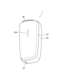
- FIG. 2 is a view of the front side of the aerosol generation device observed from diagonally above.
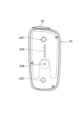
- FIG. 2 is a view of the front side of the aerosol generation device observed from diagonally below.
- FIG. 2 is a diagram showing a schematic configuration of an electronic circuit of the main unit.
- the aerosol generation device is a form of electronic cigarette.
- the substance generated by the aerosol generating device is called an aerosol.
- An aerosol is a mixture of air or other gas and minute liquid or solid particles suspended in gas.
- an aerosol generating device that generates an aerosol without combustion will be described. Inhalation of the aerosol generated by the aerosol generating device is also called a "puff.”
- an aerosol generating device to which a solid aerosol source can be attached will be described.
- the container for storing the solid aerosol source is called a "capsule” or a "stick-type substrate” depending on the product form. Capsules and stick-type substrates are consumables. For this reason, a replacement guideline is set for the capsule and stick-type substrate.
- FIG. 1 is a diagram of the front side of the aerosol generation device 1 observed from obliquely above.
- FIG. 2 is a view of the front side of the aerosol generation device 1 observed from obliquely below.
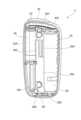
- FIG. 3 is a front view of the main unit 20 with the front panel 10 removed.
- the aerosol generation device 1 used in this embodiment has a size that allows a user to hold it in one hand.
- the aerosol generating device 1 has a main body device 20, a front panel 10 attached to the front of the main body device 20, and a shutter 30 arranged on the top surface of the main body device 20 and capable of sliding along the top surface.
- the front panel 10 is a member that can be attached to and detached from the main body device 20. The front panel 10 is attached and detached by a user.
- the front panel 10 attached to the main unit 20 covers the front portion of the main unit 20, as shown in Figures 1 and 2.
- the main unit 20 can be observed from the outside except for the front portion.
- the side, back, top, and bottom surfaces of the main unit 20 can be observed from the outside even after the front panel 10 is attached.
- a window 10A is provided in the front panel 10.
- the window 10A is provided in a position facing a light-emitting element on the main unit 20 side.
- eight LEDs 20A are provided in the main unit 20.
- the window 10A in the first embodiment is made of a material that transmits light, although the window 10A may be a slit that penetrates from the front surface to the back surface.
- the operating state of the aerosol generating device is assigned to the lighting and blinking patterns of LED 20A.
- the lighting and blinking of LED 20A is assigned to a state related to the heating of the aerosol source.
- the states related to the heating of the aerosol source include, for example, the completion of preparation for heating the aerosol source, the start of heating, the completion or end of heating, the number of aerosol sources that can be inhaled, the remaining time that can be inhaled, and an abnormality in the temperature of the main body.
- the lighting and blinking of LED 20A are assigned to the occurrence of a breakdown or malfunction of the main body device 20, the remaining battery level, charging or completion of charging, the pairing state, and the like. Malfunctions here include abnormalities related to the environmental temperature.
- the lighting and blinking of the light-emitting element is controlled by MCU 101 (see FIG. 5), which will be described later.
- the front panel 10 also has a role of buffering the transmission of heat emitted from the main unit 20. In the case of the present embodiment, only when the front panel 10 is attached to the main unit 20, generation of aerosol is permitted.
- the front panel 10 used in this embodiment is deformed when the user presses a position below the window 10A with the fingertip, and returns to its original shape when the user stops pressing. This deformation makes it possible to operate the power button 20B provided on the main unit 20 while the front panel 10 is attached to the main unit 20.
- a Type C USB (Universal Serial Bus) connector 21 is provided on the bottom side of the main unit 20.
- the shape and type of the USB connector 21 are merely an example.
- the USB connector 21 is used to charge the battery 50 (see FIG. 4) built into the main unit 20.
- USB is merely an example. Receptacles and plugs that comply with other standards may be used, but the following description will be given taking the example of using a USB connector 21 and USB plug.
- An insertion hole 22 (see FIG. 4) for inserting a stick-shaped substrate containing an aerosol source is provided on the top surface of the main body device 20.
- the insertion hole 22 is exposed by sliding the shutter 30 to the open position, and is concealed by sliding the shutter 30 to the closed position.
- the stick-shaped substrate used in this embodiment has a structure in which a solid aerosol source is housed in a substantially cylindrical paper tube.
- a magnet for example, is attached to the back surface of the shutter 30.
- a Hall IC is attached to the main body device 20 within the movable range of the shutter 30.
- the Hall IC is a magnetic sensor that is composed of a Hall element and an operational amplifier, and outputs a voltage according to the strength of the magnetic field that crosses the Hall element.
- the opening and closing of the shutter 30 is detected from a change in voltage output from the Hall IC accompanying the sliding of the shutter 30. That is, it is detected whether the shutter 30 is in the open position or the closed position.
- the power button 20B is located approximately in the center of the front of the main unit 20. As described above, the power button 20B can be operated with the front panel 10 attached.
- the power button 20B is used, for example, to turn the power of the main device 20 on and off, to turn on and off the power supply to the heater unit 40 (see Figure 4) that heats the aerosol source, and to instruct Bluetooth (registered trademark) pairing.
- pressing the power button 20B for a long time for example, for 5 seconds or more
- BLE Bluetooth Low Energy
- magnets 20C used to attach the front panel 10 are located at the top and bottom of the front of the main unit 20.
- the magnets 20C are located opposite a magnet (not shown) located on the inside of the front panel 10. For example, if the magnet on the front panel 10 has a north pole, the magnet 20C on the main unit 20 side has a south pole.
- the front panel 10 is removably attached to the main unit 20 by the attractive force between the magnets.
- Either the magnet on the front panel 10 side or the magnet 20C on the main unit 20 side may be a piece of iron or other magnetic metal.
- the attachment of the front panel 10 to the main unit 20 is detected by a Hall IC provided on the main unit 20 side.
- various electronic components necessary for generating aerosol are built into the main device 20.
- the device configuration in which the front panel 10 is attached to the main device 20 is referred to as the aerosol generating device 1, but in the narrow sense, the main device 20 is referred to as the aerosol generating device.
- FIG. 4 is a diagram showing an example of the internal configuration of the main unit 20 that appears when the front panel 10 is removed.
- a heater unit 40 In the main device 20 in the first embodiment, there are provided a heater unit 40, a battery 50, an MCU (Micro Control Unit) board 100, a USB connector board 200, an LED board 300, a Hall IC board 400, a vibrator 60, and a chassis 500 to which these components are attached.
- MCU Micro Control Unit
- USB connector board 200 In other words, there are four separate boards provided within the main device 20. The four boards are spaced apart from each other.
- the heater unit 40 is a unit that heats the stick-shaped substrate inserted into the insertion hole 22.
- the insertion hole 22 is defined as a space surrounded by the inner wall of a cylindrical container 22A.
- the container 22A used in the first embodiment has a bottom, although a container 22A without a bottom may also be used.
- a flat portion is provided on the side wall thereof. In other words, the flat portion is provided on a cross section obtained when the container 22A is cut along a plane perpendicular to the axis of the container 22A.
- the flat portion compresses and deforms the side of the stick-shaped substrate inserted into the opening of the insertion hole 22, improving heating efficiency.
- the cross-sectional shape may be approximately circular, approximately elliptical, or approximately polygonal.
- the cross-sectional shape may be the same from the opening side to the bottom surface, or it may change from the opening side to the bottom surface.
- the container 22A is preferably made of a metal having high thermal conductivity.
- the container 22A is made of, for example, stainless steel.
- a film-like heater HTR (see FIG. 5 ) that covers the outer peripheral surface is disposed on the outer periphery of the container 22A.
- the heater HTR generates heat by consuming power supplied from a battery 50. When the heater HTR generates heat, the stick-shaped substrate is heated from the outer periphery, and an aerosol is generated.
- the heater unit 40 is connected to a heater connector Cn (see FIG. 5) provided on the USB connector board 200 and receives power.
- the heater unit 40 is an example of a heating section that heats a substrate including an aerosol source.
- the battery 50 is a power source that supplies the power required for the operation of the circuit unit built into the main unit 20.
- a rechargeable lithium ion secondary battery or the like is used as the battery 50.
- the power of the battery 50 is supplied to each part through a power supply line connected to the negative and positive electrodes (not shown).
- the MCU board 100 is a board on which the MCU 101 that controls the operation of the entire device is mounted.
- the MCU 101 is a so-called controller.
- the operation of the MCU 101 is determined through the execution of firmware or a program that runs on the firmware.
- the MCU 101 controls heating by the heater unit 40.
- the MCU 101 is an example of a control unit that controls heating by the heating unit.
- the USB connector board 200 is a board on which the USB connector 21 is mounted.
- the USB connector 21 is used to receive power from an external power source via a USB cable.
- the USB connector board 200 also has a heater connector Cn and the like mounted thereon. The heater connector Cn is used to supply power to the heater unit 40.
- the LED board 300 is a board on which the LEDs 20A are mounted.
- the LEDs 20A are arranged in a row on the LED board 300.
- the number of LEDs 20A in the first embodiment is eight, but this number is not shown in Fig. 4.
- the number of LEDs 20A and their arrangement on the LED board 300 can be changed as desired.
- the Hall IC board 400 is a board on which a Hall IC that detects whether the shutter 30 is open or closed is mounted.
- the vibrator 60 is a device that vibrates to notify the user of various information regarding the aerosol generation device 1 through the case of the main body device 20.
- Fig. 5 is a diagram showing a schematic configuration of an electronic circuit of the main device 20. Note that Fig. 5 shows only the main electronic components of the MCU board 100 and the USB connector board 200, and omits the LED board 300 and the Hall IC board 400.
- the wiring shown by the thick solid line in FIG. 5 is wiring (connected to the ground provided in the main device 20) that has the same potential as the reference potential (ground potential) of the main device 20, and this wiring will be referred to as a ground line below.
- electronic components in which multiple circuit elements are made into chips are shown as rectangles, and the symbols of various terminals are written inside the rectangles.
- the power supply terminal VCC and power supply terminal VDD mounted on the chip each indicate a high-potential side power supply terminal.
- the power supply terminal VSS and ground terminal GND mounted on the chip each indicate a low-potential side (reference potential side) power supply terminal.
- the difference between the potential of the high-potential side power supply terminal and the potential of the low-potential side power supply terminal becomes the power supply voltage.
- the electronic components made into chips use this power supply voltage to execute various functions.
- the MCU board 100 is provided with the following main electronic components: an MCU 101 that controls the entire aerosol generating device 1; a charging IC 102 that controls the charging of the battery 50; a load switch (hereinafter, LSW) 103 that is composed of a combination of capacitors, resistors, transistors, etc.; and a step-up/step-down DC/DC converter 104 (in the figure, it is written as step-up/step-down DC/DC 104).
- LSW load switch
- the ground terminals GND of the charging IC 102, the LSW 103, and the step-up/step-down DC/DC converter 104 are connected to the ground line.
- the main electronic components of the USB connector board 200 are a power connector electrically connected to the battery 50 (the battery 50 connected to this power connector is shown in the figure), a step-up DC/DC converter 201 (shown as step-up DC/DC 201 in the figure), a protection IC 202, an overvoltage protection IC 203, a USB connector 21, switches S3 to S5 made up of MOSFETs, an operational amplifier OP1, and a pair of heater connectors Cn (positive and negative) electrically connected to the heater HTR.
- the two ground terminals GND of the USB connector 21, the ground terminal GND of the step-up DC/DC converter 201, the ground terminal GND of the overvoltage protection IC 203, and the negative power supply terminal of the operational amplifier OP1 are each connected to a ground line.
- the two power input terminals V BUS of the USB connector 21 are connected to an input terminal IN of an overvoltage protection IC 203 via a protection element such as a fuse Fs.
- a USB plug is connected to the USB connector 21 and a USB cable including this USB plug is connected to an external power supply, a USB voltage V USB is supplied to the two power input terminals V BUS of the USB connector 21.
- a voltage divider circuit Pa which is made up of a series circuit of two resistors, is connected to the input terminal IN of the overvoltage protection IC 203.
- the other end of the voltage divider circuit Pa is connected to the ground line.
- the connection point of the two resistors that make up the voltage divider circuit Pa is connected to the voltage detection terminal OVLo of the overvoltage protection IC 203.
- the overvoltage protection IC 203 When the voltage input to the voltage detection terminal OVLo of the overvoltage protection IC 203 is below the threshold, the overvoltage protection IC 203 outputs the voltage input to the input terminal IN from the output terminal OUT.
- the overvoltage protection IC 203 stops the voltage output from the output terminal OUT (cuts off the electrical connection between the LSW 103 and the USB connector 21) to protect electronic components downstream of the overvoltage protection IC 203.
- the output terminal OUT of the overvoltage protection IC 203 is connected to the input terminal VIN of the LSW 103.
- a voltage divider circuit Pf consisting of a series circuit of two resistors is connected to the input terminal VIN of the LSW103.
- the other end of the voltage divider circuit Pf is connected to the ground line.
- the connection point of the two resistors that make up the voltage divider circuit Pf is connected to the control terminal ON of the LSW103.
- the collector terminal of the bipolar transistor S2 is connected to the control terminal ON of the LSW103.
- the emitter terminal of the bipolar transistor S2 is connected to the ground line.
- the base terminal of the bipolar transistor S2 is connected to the MCU101.
- the output terminal VOUT of the LSW103 is connected to the input terminal VBUS of the charging IC102.
- the MCU101 turns on the bipolar transistor S2 while there is no USB connection.
- the control terminal ON of LSW103 is connected to the ground line via bipolar transistor S2, so that a low-level signal is input to the control terminal ON of LSW103.
- the bipolar transistor S2 connected to the LSW 103 is turned off by the MCU 101.
- the bipolar transistor S2 is turned off, the USB voltage V USB divided by the voltage divider circuit Pf is input to the control terminal ON of the LSW 103. Therefore, when the USB connection is made and the bipolar transistor S2 is turned off, a high-level signal is input to the control terminal ON of the LSW 103. As a result, the LSW 103 outputs the USB voltage V USB supplied from the USB cable from the output terminal VOUT.
- the positive terminal of the battery 50 is connected to the power supply terminal VDD of the protection IC 202, the input terminal VIN of the step-up DC/DC converter 201, and the charging terminal bat of the charging IC 102. Therefore, the power supply voltage V BAT of the battery 50 is supplied to the protection IC 202, the charging IC 102, and the step-up DC/DC converter 201.
- a resistor Ra, a switch Sa composed of a MOSFET, and a switch Sb composed of a MOSFET are connected in series to the negative terminal of the battery 50 in this order.
- a current detection terminal CS of the protection IC 202 is connected to the connection point of the resistor Ra and the switch Sa.
- the control terminals of the switches Sa and Sb are connected to the protection IC 202.
- the protection IC 202 obtains the current value flowing through the resistor Ra when the battery 50 is charged or discharged from the voltage input to the current detection terminal CS, and when this current value becomes excessive (in the case of an overcurrent), it controls the opening and closing of the switches Sa and Sb to stop charging or discharging the battery 50, thereby protecting the battery 50. More specifically, when an excessive current value is obtained when the battery 50 is charged, the protection IC 202 turns off the switch Sb to stop charging the battery 50. When an excessive current value is obtained when the battery 50 is discharged, the protection IC 202 turns off the switch Sa to stop discharging the battery 50.
- the protection IC 202 controls the opening and closing of the switches Sa and Sb to stop charging or discharging the battery 50, thereby protecting the battery 50. More specifically, when the protection IC 202 detects a charging overcurrent of the battery 50, it turns off the switch Sb to stop charging the battery 50. When the protection IC 202 detects a discharging overcurrent of the battery 50, it turns off the switch Sa to stop discharging the battery 50.
- One end of a reactor Lc is connected to the switching terminal SW of the boost DC/DC converter 201.
- the other end of this reactor Lc is connected to the input terminal VIN of the boost DC/DC converter 201.
- the boost DC/DC converter 201 boosts the input voltage by controlling the on/off of an internal transistor connected to the switching terminal SW, and outputs it from the output terminal VOUT.
- the input terminal VIN of the boost DC/DC converter 201 constitutes the high-potential power supply terminal of the boost DC/DC converter 201.
- the boost DC/DC converter 201 performs a boost operation when the signal input to the enable terminal EN is at a high level.
- the signal input to the enable terminal EN of the boost DC/DC converter 201 may be controlled to a low level by the MCU 101.
- the MCU 101 may not control the signal input to the enable terminal EN of the step-up DC/DC converter 201, thereby making the potential of the enable terminal EN indefinite.
- the source terminal of switch S4 which is composed of a P-channel MOSFET, is connected to the output terminal VOUT of step-up DC/DC converter 201.
- the gate terminal of switch S4 is connected to MCU101.
- One end of resistor Rs is connected to the drain terminal of switch S4.
- the other end of resistor Rs is connected to the positive electrode side heater connector Cn, which is connected to one end of heater HTR.
- a voltage divider circuit Pb consisting of two resistors is connected to the connection point between switch S4 and resistor Rs. The connection point of the two resistors that make up voltage divider circuit Pb is connected to MCU101.
- the gate terminal of switch S3 is connected to the MCU 101.
- the drain terminal of switch S3 is connected to the connection line between resistor Rs and the positive electrode side heater connector Cn.
- a circuit including switch S3 and a circuit including switch S4 and resistor Rs are connected in parallel between the output terminal VOUT of step-up DC/DC converter 201 and the positive electrode side of heater connector Cn.
- the circuit including switch S3 does not have a resistor, and therefore has a lower resistance than the circuit including switch S4 and resistor Rs.
- the non-inverting input terminal of the operational amplifier OP1 is connected to the connection line between the resistor Rs and the positive heater connector Cn.
- the inverting input terminal of the operational amplifier OP1 is connected to the negative heater connector Cn connected to the other end of the heater HTR and to the drain terminal of the switch S5 composed of an N-channel MOSFET.
- the source terminal of the switch S5 is connected to the ground line.
- the gate terminal of the switch S5 is connected to the MCU 101, the anode of the diode D4, and the enable terminal EN of the step-up DC/DC converter 201.
- the cathode of the diode D4 is connected to a flip-flop (not shown) that outputs a low-level signal when the temperature of the heater HTR becomes excessive.
- One end of the resistor R4 is connected to the output terminal of the operational amplifier OP1.
- the other end of the resistor R4 is connected to the MCU 101.
- the charging IC 102 has a charging function of charging the battery 50 based on the USB voltage VUSB input to the input terminal VBUS.
- the charging IC 102 acquires the charging current and charging voltage of the battery 50 from terminals and wiring (not shown), and performs charging control of the battery 50 (control of power supply from the charging terminal bat to the battery 50) based on these.
- the charging IC 102 further includes a V BAT power pass function and an OTG function.
- the V BAT power pass function is a function for outputting a system power supply voltage Vcc0, which is approximately equal to the power supply voltage V BAT input to the charging terminal bat, from the output terminal SYS.
- the OTG function is a function for outputting a system power supply voltage Vcc4, which is obtained by boosting the power supply voltage V BAT input to the charging terminal bat, from the input terminal VBUS.
- the on/off of the OTG function of the charging IC 102 is controlled by the MCU 101 through serial communication using the communication line LN. In the OTG function, the power supply voltage V BAT input to the charging terminal bat may be output directly from the input terminal VBUS.
- the power supply voltage V BAT and the system power supply voltage Vcc4 are approximately equal.
- multiple signal lines such as a data line for data transmission and a clock line for synchronization are required, but only one signal line is shown for simplification.
- the output terminal SYS of the charging IC 102 is connected to the input terminal VIN of the step-up/step-down DC/DC converter 104.
- One end of the reactor La is connected to the switching terminal SW of the charging IC 102.
- the other end of the reactor La is connected to the output terminal SYS of the charging IC 102.
- the charging enable terminal CE( ⁇ ) of the charging IC 102 is connected to the MCU 101 via a resistor.
- a resistor is connected to the input terminal VIN and the enable terminal EN of the step-up/step-down DC/DC converter 104.
- the system power supply voltage Vcc0 is input from the output terminal SYS of the charging IC 102 to the input terminal VIN of the step-up/step-down DC/DC converter 104
- the signal input to the enable terminal EN of the step-up/step-down DC/DC converter 104 becomes high level, and the step-up/step-down DC/DC converter 104 starts a step-up or step-down operation.
- the step-up/step-down DC/DC converter 104 generates a system power supply voltage Vcc1 by stepping up or stepping down the system power supply voltage Vcc0 input to the input terminal VIN by switching control of the built-in transistor connected to the reactor Lb, and outputs it from the output terminal VOUT.
- the output terminal VOUT of the step-up/step-down DC/DC converter 104 is connected to the feedback terminal FB of the step-up/step-down DC/DC converter 104 and the power supply terminal VDD of the MCU 101.
- a power supply line PL1 is a line through which the system power supply voltage Vcc1 output from the output terminal VOUT of the step-up/step-down DC/DC converter 104 is supplied.
- a positive power supply terminal of an operational amplifier OP1 is connected to the power supply line PL1.
- the step-up/step-down DC/DC converter 104 is an example of a power supply unit that supplies power source power to the control unit.
- the output terminal OUT of the overvoltage protection IC 203 is connected to the MCU 101, when a USB plug connected to an external device is connected to the USB connector 21, a high-level signal is input to the MCU 101.
- the MCU 101 may break down, unable to perform heating control normally, and causing overheating or the like. Therefore, in the first embodiment, a high-level signal is prevented from being input to the MCU 101 when the system power supply voltage Vcc1 is not applied to the MCU 101.
- the acknowledge terminal ACK of the overvoltage protection IC 203 is connected to the MCU 101, and a signal from the acknowledge terminal ACK is output to the MCU 101 via a signal line L_DET .
- the output from the acknowledge terminal ACK is of an open drain type. That is, the output from the acknowledge terminal ACK is connected to the ground when it is at a low level, and is not connected to anything when it is at a high level.
- the system power supply voltage Vcc1 is applied to the MCU 101 when it is at a high level.
- the USB plug is connected to the USB connector 21, a low level signal is output.
- the signal line L DET is an example of a connection signal line
- the overvoltage protection IC 203 is an example of an output unit that outputs a low signal to the control unit via the connection signal line when connected to an external device.
- the step-up/step-down DC/DC converter 104 is an example of a power supply unit connected to a connection signal line via a resistor.
- ⁇ Effects> In the aerosol generating device 1 according to the present embodiment, when connected to an external device, a low level signal is output to the MCU 101 via the signal line L DET , and the step-up/step-down DC/DC converter 104 is connected to the signal line L DET via a resistor Rp.
- the system power supply voltage Vcc1 when the system power supply voltage Vcc1 is not applied to the MCU 101, the MCU 101 is connected to an external device and a high level signal is output to the MCU 101, thereby reducing the possibility of the MCU 101 breaking down.
- the aerosol source is described as being solid, but the aerosol source may be liquid.
- the aerosol source is liquid, a method is adopted in which the aerosol source is guided to a thin tube called a wick by using capillary action, and the aerosol source is evaporated by heating a coil wound around the wick.
- the aerosol generating device that generates an aerosol by heating a solid aerosol source has been described, but the aerosol generating device may generate an aerosol by separately heating a solid aerosol source and a liquid aerosol source.
- This type of aerosol generating device is also called a hybrid aerosol generating device.
- An aerosol generating device comprising a heating unit that heats a substrate including an aerosol source, a control unit that controls heating by the heating unit, a power supply unit that supplies power to the control unit, and an output unit that outputs a low signal to the control unit via a connection signal line when connected to an external device, wherein the power supply unit is connected to the connection signal line via a resistor.
- a power supply unit for an aerosol generating device comprising a control unit that controls the heating of a substrate including an aerosol source, a power supply unit that supplies power to the control unit, and an output unit that outputs a low signal to the control unit via a connection signal line when connected to an external device, wherein the power supply unit is connected to the connection signal line via a resistor.
- 1...aerosol generating device 10...front panel, 20...main body device, 21...USB connector, 22...insertion hole, 24...LED, 30...shutter, 40...heater unit, 50...battery, 60...vibrator, 100...MCU board, 101...MCU, 104...step-up/step-down DC/DC converter, 200...USB connector board, 203...overvoltage protection IC, 300...LED board, 400...Hall IC board, 500...chassis
Landscapes
- Engineering & Computer Science (AREA)
- Power Engineering (AREA)
- Computer Networks & Wireless Communication (AREA)
- Charge And Discharge Circuits For Batteries Or The Like (AREA)
Priority Applications (6)
| Application Number | Priority Date | Filing Date | Title |
|---|---|---|---|
| PCT/JP2023/024186 WO2025004268A1 (ja) | 2023-06-29 | 2023-06-29 | エアロゾル生成装置、及びエアロゾル生成装置の電源ユニット |
| EP23943663.7A EP4736677A1 (en) | 2023-06-29 | 2023-06-29 | Aerosol generation device and power supply unit for aerosol generation device |
| CN202380099076.1A CN121263086A (zh) | 2023-06-29 | 2023-06-29 | 气溶胶产生装置和用于气溶胶产生装置的供电单元 |
| KR1020257040417A KR20260003307A (ko) | 2023-06-29 | 2023-06-29 | 에어로졸 생성 장치 및 에어로졸 생성 장치를 위한 전력 공급 유닛 |
| JP2025529125A JPWO2025004268A1 (cg-RX-API-DMAC7.html) | 2023-06-29 | 2023-06-29 | |
| TW112138334A TW202500040A (zh) | 2023-06-29 | 2023-10-05 | 霧氣生成裝置及霧氣生成裝置的電源單元 |
Applications Claiming Priority (1)
| Application Number | Priority Date | Filing Date | Title |
|---|---|---|---|
| PCT/JP2023/024186 WO2025004268A1 (ja) | 2023-06-29 | 2023-06-29 | エアロゾル生成装置、及びエアロゾル生成装置の電源ユニット |
Publications (1)
| Publication Number | Publication Date |
|---|---|
| WO2025004268A1 true WO2025004268A1 (ja) | 2025-01-02 |
Family
ID=93937969
Family Applications (1)
| Application Number | Title | Priority Date | Filing Date |
|---|---|---|---|
| PCT/JP2023/024186 Ceased WO2025004268A1 (ja) | 2023-06-29 | 2023-06-29 | エアロゾル生成装置、及びエアロゾル生成装置の電源ユニット |
Country Status (6)
| Country | Link |
|---|---|
| EP (1) | EP4736677A1 (cg-RX-API-DMAC7.html) |
| JP (1) | JPWO2025004268A1 (cg-RX-API-DMAC7.html) |
| KR (1) | KR20260003307A (cg-RX-API-DMAC7.html) |
| CN (1) | CN121263086A (cg-RX-API-DMAC7.html) |
| TW (1) | TW202500040A (cg-RX-API-DMAC7.html) |
| WO (1) | WO2025004268A1 (cg-RX-API-DMAC7.html) |
Citations (7)
| Publication number | Priority date | Publication date | Assignee | Title |
|---|---|---|---|---|
| EP2687993A1 (en) | 2012-07-16 | 2014-01-22 | VeriFone, Inc. | USB apparatus and embedded system incorporating same |
| CN203482903U (zh) * | 2013-10-17 | 2014-03-19 | 向智勇 | 触摸式控制电路和烟盒电路 |
| CN213402973U (zh) | 2020-10-12 | 2021-06-08 | 深圳市道通科技股份有限公司 | 接口识别电路和电子设备 |
| JP2022016288A (ja) * | 2020-07-09 | 2022-01-21 | 日本たばこ産業株式会社 | エアロゾル生成装置の電源ユニット |
| JP2022044543A (ja) * | 2020-09-07 | 2022-03-17 | 日本たばこ産業株式会社 | エアロゾル発生システム |
| WO2022239406A1 (ja) * | 2021-05-10 | 2022-11-17 | 日本たばこ産業株式会社 | エアロゾル生成装置の電源ユニット |
| JP2023521945A (ja) * | 2020-04-22 | 2023-05-26 | ジェイティー インターナショナル エス.エイ. | エアロゾル発生装置用の電気システム |
-
2023
- 2023-06-29 JP JP2025529125A patent/JPWO2025004268A1/ja active Pending
- 2023-06-29 CN CN202380099076.1A patent/CN121263086A/zh active Pending
- 2023-06-29 EP EP23943663.7A patent/EP4736677A1/en active Pending
- 2023-06-29 WO PCT/JP2023/024186 patent/WO2025004268A1/ja not_active Ceased
- 2023-06-29 KR KR1020257040417A patent/KR20260003307A/ko active Pending
- 2023-10-05 TW TW112138334A patent/TW202500040A/zh unknown
Patent Citations (7)
| Publication number | Priority date | Publication date | Assignee | Title |
|---|---|---|---|---|
| EP2687993A1 (en) | 2012-07-16 | 2014-01-22 | VeriFone, Inc. | USB apparatus and embedded system incorporating same |
| CN203482903U (zh) * | 2013-10-17 | 2014-03-19 | 向智勇 | 触摸式控制电路和烟盒电路 |
| JP2023521945A (ja) * | 2020-04-22 | 2023-05-26 | ジェイティー インターナショナル エス.エイ. | エアロゾル発生装置用の電気システム |
| JP2022016288A (ja) * | 2020-07-09 | 2022-01-21 | 日本たばこ産業株式会社 | エアロゾル生成装置の電源ユニット |
| JP2022044543A (ja) * | 2020-09-07 | 2022-03-17 | 日本たばこ産業株式会社 | エアロゾル発生システム |
| CN213402973U (zh) | 2020-10-12 | 2021-06-08 | 深圳市道通科技股份有限公司 | 接口识别电路和电子设备 |
| WO2022239406A1 (ja) * | 2021-05-10 | 2022-11-17 | 日本たばこ産業株式会社 | エアロゾル生成装置の電源ユニット |
Also Published As
| Publication number | Publication date |
|---|---|
| TW202500040A (zh) | 2025-01-01 |
| JPWO2025004268A1 (cg-RX-API-DMAC7.html) | 2025-01-02 |
| KR20260003307A (ko) | 2026-01-06 |
| CN121263086A (zh) | 2026-01-02 |
| EP4736677A1 (en) | 2026-05-06 |
Similar Documents
| Publication | Publication Date | Title |
|---|---|---|
| JP7336624B2 (ja) | エアロゾル生成装置の電源ユニット | |
| KR20230155598A (ko) | 에어로졸 생성 장치의 전원 유닛 | |
| JP7631554B2 (ja) | エアロゾル生成装置の電源ユニット | |
| EP4338615A1 (en) | Power supply unit for aerosol generation device | |
| EP4088591B1 (en) | Power supply unit of aerosol generating device | |
| WO2022239405A1 (ja) | エアロゾル生成装置の電源ユニット | |
| JP7692055B2 (ja) | エアロゾル生成装置の電源ユニット | |
| KR20230162033A (ko) | 에어로졸 생성 장치의 전원 유닛 | |
| KR20240006535A (ko) | 에어로졸 생성 장치의 회로 유닛 및 에어로졸 생성 장치 | |
| EP4445783A1 (en) | Power supply unit for aerosol generation device | |
| WO2023105771A1 (ja) | エアロゾル生成装置の電源ユニット | |
| WO2025004265A1 (ja) | エアロゾル生成装置 | |
| EP4736677A1 (en) | Aerosol generation device and power supply unit for aerosol generation device | |
| JP7748397B2 (ja) | エアロゾル生成装置の回路ユニット及びエアロゾル生成装置 | |
| CN118369006A (zh) | 气溶胶生成装置的电源单元 | |
| KR20240095355A (ko) | 에어로졸 생성 장치의 전원 유닛 | |
| WO2022239407A1 (ja) | エアロゾル生成装置の電源ユニット | |
| WO2022239408A1 (ja) | エアロゾル生成装置の電源ユニット | |
| CN118382372A (zh) | 气溶胶生成装置的电源单元 | |
| EA052897B1 (ru) | Блок питания для устройства генерации аэрозоля |
Legal Events
| Date | Code | Title | Description |
|---|---|---|---|
| 121 | Ep: the epo has been informed by wipo that ep was designated in this application |
Ref document number: 23943663 Country of ref document: EP Kind code of ref document: A1 |
|
| ENP | Entry into the national phase |
Ref document number: 1020257040417 Country of ref document: KR Free format text: ST27 STATUS EVENT CODE: A-0-1-A10-A15-NAP-PA0105 (AS PROVIDED BY THE NATIONAL OFFICE) |
|
| WWE | Wipo information: entry into national phase |
Ref document number: 1020257040417 Country of ref document: KR |
|
| ENP | Entry into the national phase |
Ref document number: 2025529125 Country of ref document: JP Kind code of ref document: A |
|
| WWE | Wipo information: entry into national phase |
Ref document number: 2025529125 Country of ref document: JP |
|
| WWP | Wipo information: published in national office |
Ref document number: 1020257040417 Country of ref document: KR |
|
| WWE | Wipo information: entry into national phase |
Ref document number: 2023943663 Country of ref document: EP |
|
| NENP | Non-entry into the national phase |
Ref country code: DE |
|
| ENP | Entry into the national phase |
Ref document number: 2023943663 Country of ref document: EP Effective date: 20260129 |
|
| ENP | Entry into the national phase |
Ref document number: 2023943663 Country of ref document: EP Effective date: 20260129 |
|
| WWP | Wipo information: published in national office |
Ref document number: 2023943663 Country of ref document: EP |