WO2025004262A1 - 制御装置 - Google Patents
制御装置 Download PDFInfo
- Publication number
- WO2025004262A1 WO2025004262A1 PCT/JP2023/024167 JP2023024167W WO2025004262A1 WO 2025004262 A1 WO2025004262 A1 WO 2025004262A1 JP 2023024167 W JP2023024167 W JP 2023024167W WO 2025004262 A1 WO2025004262 A1 WO 2025004262A1
- Authority
- WO
- WIPO (PCT)
- Prior art keywords
- destination
- control program
- data
- distribution
- delivery
- Prior art date
- Legal status (The legal status is an assumption and is not a legal conclusion. Google has not performed a legal analysis and makes no representation as to the accuracy of the status listed.)
- Ceased
Links
Images





Classifications
-
- G—PHYSICS
- G05—CONTROLLING; REGULATING
- G05B—CONTROL OR REGULATING SYSTEMS IN GENERAL; FUNCTIONAL ELEMENTS OF SUCH SYSTEMS; MONITORING OR TESTING ARRANGEMENTS FOR SUCH SYSTEMS OR ELEMENTS
- G05B19/00—Program-control systems
- G05B19/02—Program-control systems electric
- G05B19/18—Numerical control [NC], i.e. automatically operating machines, in particular machine tools, e.g. in a manufacturing environment, so as to execute positioning, movement or co-ordinated operations by means of program data in numerical form
- G05B19/408—Numerical control [NC], i.e. automatically operating machines, in particular machine tools, e.g. in a manufacturing environment, so as to execute positioning, movement or co-ordinated operations by means of program data in numerical form characterised by data handling or data format, e.g. reading, buffering or conversion of data
-
- G—PHYSICS
- G05—CONTROLLING; REGULATING
- G05B—CONTROL OR REGULATING SYSTEMS IN GENERAL; FUNCTIONAL ELEMENTS OF SUCH SYSTEMS; MONITORING OR TESTING ARRANGEMENTS FOR SUCH SYSTEMS OR ELEMENTS
- G05B19/00—Program-control systems
- G05B19/02—Program-control systems electric
- G05B19/18—Numerical control [NC], i.e. automatically operating machines, in particular machine tools, e.g. in a manufacturing environment, so as to execute positioning, movement or co-ordinated operations by means of program data in numerical form
- G05B19/4155—Numerical control [NC], i.e. automatically operating machines, in particular machine tools, e.g. in a manufacturing environment, so as to execute positioning, movement or co-ordinated operations by means of program data in numerical form characterised by program execution, i.e. part program or machine function execution, e.g. selection of a program
Definitions
- This disclosure relates to a control device that transmits data to a destination depending on the execution status of a control program.
- control data is temporarily buffered within the control device and then transmitted as a bundle.
- a control device controls industrial machinery such as a machine tool or a robot, and in response to a request from one or more application programs executed by at least one information processing device to acquire data of a data item related to the control of the industrial machinery, the control device transmits the data of the requested data item to the information processing device based on a priority for each data item and time information related to an update interval for data transmission.
- control device when data is sent from a numerical control device, which is a control device, to an analysis device, which is an information processing device, depending on the analysis device, it is possible to analyze only data of a specific processing step, rather than analyzing all data during processing. Also, there are cases where analysis data is not required for a section where the workpiece is not in contact with the workpiece (not being processed), such as during tool replacement.
- the control device transmits control data regardless of the execution state of the processing, including sections that are not necessary for the analysis of the destination analysis device. Also, when transmitting data to multiple analysis devices, the same control data is transmitted even if the analysis devices have different purposes. This places an unnecessary load on the control device and leads to a load on the network.
- control device that controls an industrial machine based on a control program and transmits acquired data to one or more distribution destinations as distribution data, and includes a control program element-specific destination information acquisition unit that acquires a control program element-specific distribution target information table for each execution block of the control program, the control program element-specific destination information table including first destination information used to determine whether the distribution data specified in advance can be transmitted, and updates second destination information of the control device based on the contents of the execution block and the control program element-specific distribution target information table, and a distribution destination determination unit that acquires a distribution destination-specific target information table including third destination information used to determine whether the distribution data can be transmitted to the distribution destination specified in advance at the time of transmission of distribution data, and determines whether the distribution data can be transmitted based on the updated second destination information and the distribution destination-specific target information table, and transmits the distribution data to the distribution destination.
- a control program element-specific destination information acquisition unit that acquires a control program element-specific distribution target information table for each execution block of the control program, the control program element-specific destination information
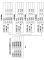
- FIG. 2 is a diagram illustrating an example of a functional block configuration of a control system according to an embodiment.
- FIG. 4 illustrates an example of a control program.
- FIG. 11 is a diagram illustrating an example of a destination information table for each control program element.
- FIG. 13 is a diagram showing an example of a flag string in a storage area “first destination information”.
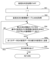
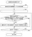
- FIG. 13 is a diagram illustrating an example of a target information table by delivery destination. 13 is a flowchart illustrating a distribution process of a control device. 7 is a flowchart illustrating detailed processing contents of the delivery destination determination processing shown in step S5 in FIG. 6.
- FIG. 13 is a diagram showing an example of a target information table by destination in which the flag column by destination and data ID is omitted.
- FIG. 13 is a diagram showing an example of a destination-specific target information table in which the destination information in the storage area “all destinations” is omitted. 7 is a flowchart of the delivery destination determination process shown in step S5 in FIG. 6.
- FIG. 1 is a diagram illustrating an example of a functional block configuration of a control system according to an embodiment.
- the control system 1 includes a control device 10 and m distribution destinations 20(1) to 20(m) serving as analysis devices (m is an integer equal to or greater than 1).
- the control device 10 and the distribution destinations 20(1) to 20(m) are connected to each other and communicate via a network (not shown) such as a LAN (Local Area Network) or the Internet.
- the control device 10 and the distribution destinations 20(1) to 20(m) are provided with a communication unit (not shown) for communicating with each other via such a connection.
- the control device 10 and the distribution destinations 20(1) to 20(m) may be directly connected to each other via a connection interface (not shown).
- the distribution destinations 20(1) to 20(m) are, for example, information processing devices (analysis devices) such as computers or tablet terminals known to those skilled in the art, and analyze the data received from the control device 10 described below.
- the distribution destinations 20(1) to 20(m) determine (estimate) the operating state of industrial machines (not shown), such as machine tools and robots, controlled by the control device 10, based on the analysis results, and transmit the determination results to the control device 10 or display them on display devices (not shown) included in the distribution destinations 20(1) to 20(m).
- distribution destinations 20 when there is no need to distinguish between the distribution destinations 20(1) to 20(m), they will also be referred to as "distribution destinations 20." Further, although the description will be given taking a machine tool as an example of industrial machinery, the invention is also applicable to various other machines such as industrial robots, service robots, forging machines, and injection molding machines.
- the control device 10 is a numerical control device known to those skilled in the art, which generates commands based on a control program and transmits the generated commands to a machine tool (not shown). In this way, the control device 10 controls the operation of the machine tool (not shown). Note that if the machine tool (not shown) is a robot or the like, the control device 10 may be a robot control device or the like. 1, the control device 10 includes a storage unit 11 and a control unit 12.
- the control unit 12 includes a control program execution unit 121 having the function of a control program element-specific destination information acquisition unit, and a delivery destination determination unit 122 having the function of a data delivery unit.
- the storage unit 11 may be a ROM (Read Only Memory), a RAM (Random Access Memory), an SSD (Solid State Drive), an HDD (Hard Disk Drive), etc.
- the storage unit 11 may store a control program executed by a control program execution unit 121 (described later), and may store data such as torque information, current information, speed information, and position information for each servo axis of a machine tool (not shown) acquired from the machine tool as distribution data for each item.
- the storage unit 11 also has a destination information table 200 for each control program element, a second destination information storage unit 300, and a target information table 400 for each distribution destination.
- the control program element-specific destination information table 200 includes a flag sequence used to determine whether or not pre-specified distribution data can be sent for each element of a block described in a control program executed by the control program execution unit 121 described below.
- the control program element-specific destination information table 200 is set and generated in advance for each control program by an operator via an input device (not shown) such as a keyboard.
- the flag sequence used to determine whether or not pre-specified distribution data can be sent is also referred to as "first destination information.”
- the control program element-specific destination information table 200 will be described below by taking the control program P shown in Fig. 2 as an example. However, the control program element-specific destination information table 200 of the other control programs is similar to the control program element-specific destination information table of the control program P in Fig. 2.
- FIG. 2 is a diagram showing an example of the control program P.
- the control program P has blocks of a preparation process such as tool replacement from the row of sequence number "N0000", a machining process A from the row of sequence number "N1000", a machining process B from the row of sequence number "N2000”, a machining process C from the row of sequence number "N3000", and a machining process Z from the row of sequence number "N9000".
- the control program P may also have blocks of multiple machining processes between the machining process C and the machining process Z.
- FIG. 3 is a diagram showing an example of the control program element destination information table 200 of the control program P. As shown in FIG. As shown in FIG.
- the control program element-specific destination information table 200 has storage areas for "target item” and "first destination information.”
- sequence numbers of blocks at which preparation steps or machining step A in the control program P in Fig. 2 start are stored as elements.
- the elements stored in the storage area "target item” are not limited to sequence numbers of machining steps, and may be elements that can be written in the control program P, for example, axis movement commands such as "X100Y100", and preparation commands such as positioning (G00) and data setting (G10).
- the elements stored in the storage area "target item” may be sequence names, auxiliary commands in M-codes, feedrate commands, tool change commands, spindle speed commands, program names, comments, etc.
- the storage area for "first destination information" in the control program element-specific destination information table 200 stores a flag string used to determine whether or not pre-specified delivery data can be sent.
- FIG. 4 is a diagram showing an example of a flag string in the storage area "first destination information.” 4, the flag string in the storage area "first destination information” indicates whether or not distribution data can be transmitted for each of the (n+1) elements (n is an integer equal to or greater than 1) in each block of the control program P.
- the flag string in the storage area "first destination information” is set in advance by an operator via an input device (not shown). Specifically, as shown in Fig.
- each flag in the flag column of the storage area "first destination information” indicates, for example, ON/OFF of display delivery and ON/OFF of delivery of data for each of the machining steps A to Z of the control program P in Fig. 2.
- each flag in the flag column of the storage area "first destination information” is not limited to elements of a machining step.
- the flag column of the storage area "first destination information” may include flags indicating whether data of elements such as axis movement commands, preparation commands such as positioning, sequence names, auxiliary commands, feedrate commands, tool change commands, spindle speed commands, program names, comments, etc. described in the control program P can be transmitted.
- the second destination information storage unit 300 stores a flag sequence of the first destination information based on an element indicating the content of a block of a control program P executed by the control program execution unit 121 (described later) and the control program element-specific destination information table 200 of the control program P.
- the flag sequence of the first destination information stored in the second destination information storage unit 300 is also referred to as "second destination information.”
- the control program execution unit 121 when the control program execution unit 121 is executing, for example, a block of machining process A of the control program P, it acquires a sequence number "N1000" indicating the start of the machining process A as an element indicating the contents of the block.
- the control program execution unit 121 refers to the acquired block element "N1000" and the control program element-specific destination information table 200, updates the flag string of the storage area "first destination information" where the storage area "target item” is "N1000" as second destination information, and stores it in the second destination information storage unit 300.
- the destination-specific target information table 400 is used to determine whether transmission is possible for each delivery data to a pre-specified destination.
- FIG. 5 is a diagram showing an example of the distribution destination target information table 400.
- the destination-specific target information table 400 has storage areas for "destination" and "target information.”
- the storage area for "distribution destination" in the distribution destination-specific target information table 400 stores distribution destinations 20(1) to 20(4) to which data such as torque information acquired from a machine tool (not shown) is distributed.
- a table of flag strings used to determine whether or not transmission is possible for each delivery destination 20 of the storage area "delivery destination" designated in advance and for each delivery data is stored.
- the target information A in the storage area "target information" of the distribution destination 20(1) is, for example, a table having storage areas “all distribution destinations” and “list of data IDs to be collected” shown in the top row of FIG. 5.
- the storage area "all distribution destinations” stores a flag string indicating whether transmission to the distribution destination 20(1) is possible.
- the storage area “list of data IDs to be collected” stores a flag string for each distribution destination and data ID, in which whether transmission is possible or not is set for each data ID of the distribution data.
- the flag strings in the storage areas "all distribution destinations” and “list of data IDs to be collected” may be set in advance by an operator via an input device not shown.
- the tables of target information B to D in the storage area "target information” are similar to those of target information A, and therefore the explanation thereof will be omitted.
- the flag strings set in the storage areas "all distribution destinations” and “list of collection target data IDs” are also collectively referred to as "third destination information.”
- the control unit 12 has a CPU (Central Processing Unit), a ROM, a RAM, a CMOS (Complementary Metal-Oxide-Semiconductor) memory, etc., which are configured to be able to communicate with each other via a bus, and are well known to those skilled in the art.
- the CPU is a processor that controls the entire control device 10.
- the CPU reads out the system program and application program stored in the ROM via the bus, and controls the entire control device 10 in accordance with the system program and application program.
- the control unit 12 is configured to realize the functions of a control program execution unit 121 and a delivery destination determination unit 122.
- the RAM stores various data such as temporary calculation data and display data.
- the CMOS memory is backed up by a battery (not shown), and is configured as a non-volatile memory that retains its stored state even when the power to the control device 10 is turned off.
- the control program execution unit 121 executes a control program P that has been input from outside or loaded from the storage unit 11.
- the control program execution unit 121 acquires the control program element-specific destination information table 200 of the control program P in FIG. 3 from the storage unit 11 for each execution block of the control program P. Then, the control program execution unit 121 refers to the element indicated by the contents of the block to be executed and the control program element-specific destination information table, updates the second destination information, and stores it in the second destination information storage unit 300.
- the control program execution unit 121 for example, reads ahead and analyzes a block of the control program P.
- control program execution unit 121 determines that the read-ahead block is a block related to the machining process A, it acquires a sequence number "N1000" indicating the start of the machining process A as an element in the block.
- the control program execution unit 121 acquires a flag string of the storage area "first destination information" in which the storage area "target item” corresponds to "N1000" from the control program element-specific destination information table.
- the control program execution unit 121 updates the acquired flag string as second destination information and stores it in the second destination information storage unit 300.
- the control program execution unit 121 executes the read-ahead block, and the control device 10 acquires data such as torque information, current information, speed information, and position information from a machine tool (not shown) and stores it in the storage unit 11.
- the delivery destination determination unit 122 acquires the delivery destination-specific target information table 400 used for determining whether or not transmission is possible for each delivery data to a pre-specified delivery destination from the storage unit 11 when transmitting the delivery data.
- the delivery destination determination unit 122 determines whether or not transmission of the delivery data is possible based on the second destination information in the second destination information storage unit 300 and the delivery destination-specific target information table 400, and transmits the delivery data determined to be possible to the delivery destination 20 determined to be possible.
- the delivery destination determination unit 122 reads, for example, the delivery destination-specific target information table 400 of Fig. 5 from the storage unit 11, and acquires target information for each delivery destination from the delivery destination-specific target information table 400.
- the delivery destination determination unit 122 calculates a logical product (AND operation) between flags using a flag string of the second destination information set in the second destination information storage unit 300 and a flag string of a storage area "all delivery destinations" included in each of the acquired target information tables.
- the delivery destination determination unit 122 determines that the delivery destination 20 of the storage area "delivery destination” corresponding to the storage area "target information" of the target for which the logical product was calculated in the delivery destination-specific target information table 400 is the delivery destination of the delivery data.
- the delivery destination determination unit 122 calculates a logical product (AND operation) between each flag, using each flag sequence for each delivery destination/data ID in the storage area "List of data IDs to be collected" of the table of target information and the flag sequence of the second destination information in the second destination information storage unit 300.
- the delivery destination determination unit 122 transmits the delivery data for which the logical product of any of the flags is "1" to the delivery destination 20 determined as the delivery destination above.
- FIG. 6 is a flowchart illustrating the control process of the control device 10. The flow shown here is repeatedly executed every time the control device 10 executes the control program P.
- step S1 the control program execution unit 121 initializes k to "1".
- step S2 the control program execution unit 121 reads the control program P from the memory unit 11, and reads ahead and analyzes the kth block of the read control program P.
- step S3 the control program execution unit 121 retrieves the control program element-specific destination information table 200 from the storage unit 11, and updates the second destination information in the second destination information storage unit 300 based on the element indicated by the contents of the kth block analyzed in step S2 and the control program element-specific destination information table 200.
- step S4 the control program execution unit 121 executes the kth block. Then, the control device 10 acquires data such as torque information, current information, speed information, and position information from the machine tool (not shown), and stores the acquired data in the storage unit 11 as distribution data for each item.
- step S5 the delivery destination determination unit 122 executes a delivery destination determination process and delivers the delivery data acquired in step S4 to the delivery destination 20 determined to be a delivery destination.
- the detailed flow of the delivery destination determination process will be described later.
- step S6 the control program execution unit 121 determines whether or not there is a next (k+1)th block in the control program P. If there is a next block, the process returns to step S2; on the other hand, if there is no next block, the distribution process ends.
- Fig. 7 is a flowchart for explaining in detail the contents of the delivery destination determination process shown in step S5 in Fig. 6.
- steps S51 to S57 indicate the process flow of the delivery destination determination unit 122. 6
- the processes of steps S1 to S4 and S6, and the delivery destination determination process of step S5 may be executed sequentially or in parallel.
- the data processed by the control program execution unit 121 may be stored in a predetermined storage area allocated to the storage unit 11, and the delivery destination determination unit 122 may read the processed data from the predetermined storage area as needed to execute the delivery destination determination process.
- step S51 the delivery destination determination unit 122 initializes i to "1".
- step S52 the delivery destination determination unit 122 retrieves the delivery destination target information table 400 from the storage unit 11.
- step S53 the delivery destination determination unit 122 initializes j to "1".
- step S54 the delivery destination determination unit 122 calculates the logical product of each flag using the flag string of the second destination information in the second destination information storage unit 300 updated in step S3 and the flag string of the storage area "all delivery destinations" of the table of the i-th storage area "target information" of the delivery destination-specific target information table 400 acquired in step S52.
- the delivery destination determination unit 122 determines whether the result of the logical product calculation is "1". If the logical product of any flag is "1", the delivery destination determination unit 122 determines that the delivery destination 20 in the i-th storage area "delivery destination" of the delivery destination-specific target information table 400 is the delivery destination. Then, the process proceeds to step S55. On the other hand, if the logical products of all flags are "0", the process proceeds to step S58.
- step S55 the delivery destination determination unit 122 calculates the logical product of each flag using the flag string of the jth data ID in the table storage area "List of data IDs to be collected” in the i-th storage area "Target information" in the delivery destination-specific target information table 400 and the flag string of the second destination information in the second destination information storage unit 300. If the logical product of any flag is "1”, processing proceeds to step S56. On the other hand, if the logical products of all flags are "0", processing proceeds to step S57.
- step S56 the distribution destination determination unit 122 distributes the distribution data of the jth data ID in the storage area "List of data IDs to be collected" to the ith distribution destination 20.
- step S57 the delivery destination determination unit 122 determines whether or not there is a next (j+1)th storage area "data ID”. If there is a next storage area "data ID”, the process returns to step S55. On the other hand, if there is no next storage area "data ID”, the process proceeds to step S58.
- step S58 the delivery destination determination unit 122 determines whether or not there is a next (i+1)th delivery destination 20. If there is a next delivery destination 20, the process returns to step S53. On the other hand, if there is no next delivery destination 20, the process ends the delivery destination determination process and proceeds to step S6 in FIG. 6.
- control device 10 can transmit data to a distribution destination in accordance with the execution state of a control program in the control device, thereby making it possible to reduce unnecessary data transmission. This eliminates unnecessary load on the control system 1, making it possible to reduce the load on the network.
- the control program execution unit 121 acquires the control program element-specific destination information table 200 from the storage unit 11 for each execution block of the control program P, but is not limited to this.
- a destination change command code such as "MxxFyyyy” may be embedded in each block of the control program P, and the control program execution unit 121 may update the second destination information in the second destination information storage unit 300 according to each destination command.
- "xx" in the destination command "MxxFyyyy” indicates a two-digit number set in advance
- "yyyy” indicates a flag string of the second destination information set by the worker as an argument.
- the destination command is an auxiliary code (M code) of "MxxFyyyy”, but is not limited to this and may be any code.
- M code auxiliary code
- the G-code "G00" of the fast-forward command does not process the workpiece. Therefore, when executing a G-code that does not process the workpiece, such as the fast-forward command "G00", the control program execution unit 121 may update the second destination information in the second destination information storage unit 300 with a flag sequence that is preset by a parameter or the like, so as not to transmit the distribution data to the distribution destination 20.
- the G code "G73" of the high-speed deep hole drilling cycle does not machine the workpiece during the escape operation.
- the control program execution unit 121 may update the second destination information in the second destination information storage unit 300 with a flag sequence previously set by a parameter or the like, so as not to transmit the distribution data to the distribution destination 20.
- the control program execution unit 121 may interpret the signal as a destination change command and update the second destination information in the second destination information storage unit 300 with a flag sequence that is preset by a parameter or the like. By doing so, the control device 10 can suppress the transmission of unnecessary data.
- a flag column for each distribution destination/data ID is set in the storage area "List of data IDs to be collected” in the table of each storage area "Target information”, but this is not limited to this.
- the flag column for destination information for each distribution destination/data ID may be omitted in the storage area "List of data IDs to be collected” in the table of each storage area "Target information”.
- FIG. 8 is a diagram showing an example of a destination-specific target information table 400 in which the flag column for each destination and data ID is omitted from the storage area "list of collection target data IDs.”
- the control device 10 transmits distribution data of all data IDs set in the storage area "list of data IDs to be collected” of the table of the storage area "target information” to the distribution destination 20 of the storage area "distribution destination” corresponding to the storage area "target information”.
- the distribution destination determination process in step S5 of the distribution process in FIG. 6 is as shown in the flowchart in FIG. 9.
- the processes in steps S51, S52, S54, and S58 are similar to those in steps S51, S52, S54, and S58 in FIG.
- step S56 a the distribution destination determination unit 122 distributes the distribution data of all the data IDs in the storage area “list of data IDs to be collected” to the i-th distribution destination 20.
- the control device 10 can simplify the delivery destination determination process and speed up the delivery process.
- FIG. 10 is a diagram showing an example of the destination-specific target information table 400 in which the destination information in the storage area "all destinations" is omitted.
- the control device 10 determines whether or not the distribution data to be sent can be sent based on each of the flag columns for each distribution destination and data ID set in the storage area "List of data IDs to be collected” in the storage area "Target information" of the target information table by distribution destination 400 and the second destination information in the second destination information storage unit 300.
- the control device 10 transmits the distribution data determined to be sendable to all distribution destinations 20.
- step S5 of the distribution process in FIG. 6 becomes the flowchart shown in FIG. 11.
- the processes in steps S52, S53, and S57 are similar to those in steps S52, S53, and S57 in FIG. 7, and therefore detailed description thereof will be omitted.
- step S55a the delivery destination determination unit 122 calculates a logical product between flags using a flag string for the jth delivery destination/data ID in the storage area "List of data IDs to be collected" in the storage area "Target information" table of the delivery destination-specific target information table 400 and a flag string for the second destination information in the second destination information storage unit 300. If the logical product of any of the flags is "1", the process proceeds to step S56b.
- step S56b the distribution destination determination unit 122 distributes the distribution data of the j-th data ID in the storage area “list of data IDs to be collected” to all of the distribution destinations 20.
- the control device 10 can simplify the delivery destination determination process and speed up the delivery process.
- the first destination information to the third destination information are set as flag strings as shown in Fig. 4, but are not limited to this.
- the first destination information to the third destination information may be set as a tag combining elements such as "processing steps A, B, C".
- each function included in the control device 10 can be realized by hardware, software, or a combination of these.
- being realized by software means being realized by a computer reading and executing a program.
- Non-transitory computer-readable media include various types of tangible recording media.
- Examples of non-transitory computer-readable media include magnetic recording media (e.g., flexible disks, magnetic tapes, hard disk drives), magneto-optical recording media (e.g., magneto-optical disks), CD-ROMs (Compact Disc Read Only Memory), CD-Rs, CD-R/Ws, and semiconductor memories (e.g., mask ROMs, PROMs (Programmable ROMs), EPROMs (Erasable PROMs), flash ROMs, and RAMs).
- the program may also be supplied to the computer by various types of temporary computer-readable media. Examples of temporary computer-readable media include electrical signals, optical signals, and electromagnetic waves.
- the temporary computer-readable media can be supplied to the computer via wired communication paths such as electric wires and optical fibers, or wireless communication paths.
- the step of writing the program to be recorded on the recording medium includes not only processes that are performed chronologically according to the order, but also processes that are not necessarily performed chronologically but are executed in parallel or individually.
- the step of writing the program may also be performed by cloud computing.
- the control device (10) is a control device that controls an industrial machine based on a control program (P) and transmits acquired data to one or more distribution destinations (20) as distribution data, and includes a control program element-specific destination information acquisition unit (121) that acquires a control program element-specific distribution target information table (200) including first destination information used to determine whether or not predetermined distribution data can be transmitted for each execution block of the control program (P) and updates second destination information of the control device (10) based on the content of the execution block and the control program element-specific distribution target information table (200), and a distribution destination determination unit (122) that acquires a distribution destination-specific target information table (400) including third destination information used to determine whether or not transmission is possible for a predetermined distribution destination (20) and for each distribution data when transmitting distribution data, determines whether or not transmission is possible for the distribution data based on the updated second destination information and the distribution destination-specific target information table (400), and transmits the distribution data
- the destination information acquisition unit (121) for each control program element updates the second destination information based on the first destination information specified in advance for each element including any one of a program name, a block number, a sequence name, a command, and a comment constituting the control program (P) and the element of the execution block.
- the control program element-specific destination information acquisition unit (121) updates the second destination information based on an argument set in a specific command included in the control program (P).
- Control system 10 Control device 11 Storage unit 200 Destination information table by control program element 300 Second destination information storage unit 400 Target information table by delivery destination 12 Control unit 121 Control program execution unit 122 Delivery destination determination unit 20(1) to 20(m) Delivery destination P Control program
Landscapes
- Engineering & Computer Science (AREA)
- Human Computer Interaction (AREA)
- Manufacturing & Machinery (AREA)
- Physics & Mathematics (AREA)
- General Physics & Mathematics (AREA)
- Automation & Control Theory (AREA)
- Stored Programmes (AREA)
- Information Transfer Between Computers (AREA)
Abstract
Description
例えば、制御装置は、工作機械やロボット等の産業機械を制御し、産業機械の制御に関するデータ項目のデータのうち少なくとも1つの情報処理装置が実行する1つ以上のアプリケーションプログラムからの取得要求に対して、取得要求されたデータ項目のデータを送信するにあたり、データ項目毎に優先度とデータの送信の更新間隔に関する時間情報とに基づいて、取得要求されたデータ項目のデータを情報処理装置に送信する技術が知られている。例えば、特許文献1参照。
特許文献1等の従来技術では、制御装置は加工の実行状態によらず、また、送信先の解析装置にとって解析に不要な区間も含め、制御データを送信していた。また、複数の解析装置へデータを送信する場合も解析装置それぞれの目的が異なっていても、同じ制御データを送信していた。これは、制御装置に不要な負荷を与え、また、ネットワークの負荷につながっていた。
以下、一実施形態に係る制御システムについて、図を参照しながら詳細に説明する。
図1は、一実施形態に係る制御システムの機能ブロック構成の一例を示す図である。
図1に示すように、制御システム1は、制御装置10、及び解析装置としてのm個の配信先20(1)~20(m)を有する(mは1以上の整数)。
制御装置10、及び配信先20(1)~20(m)は、LAN(Local Area Network)やインターネット等の図示しないネットワークを介して相互に接続されて通信を行う。この場合、制御装置10、及び配信先20(1)~20(m)は、かかる接続によって相互に通信を行うための図示しない通信部を備えている。なお、制御装置10、及び配信先20(1)~20(m)は、図示しない接続インタフェースを介して互いに直接接続されてもよい。
なお、以下では、配信先20(1)~20(m)を区別する必要がない場合、「配信先20」ともいう。
また、産業機械として工作機械の場合を例示して説明するが、産業用ロボット、サービス用ロボット、鍛圧機械及び射出成形機といった様々な機械に対しても適用可能である。
図1に示すように、制御装置10は、記憶部11及び制御部12を有する。そして、制御部12は、制御プログラム要素別宛先情報取得部の機能を有する制御プログラム実行部121、及びデータ配信部の機能を有する配信先判定部122を有する。
以下では、図2に示す制御プログラムPを例示して制御プログラム要素別宛先情報テーブル200について説明する。しかしながら、他の制御プログラムの制御プログラム要素別宛先情報テーブル200についても、図2の制御プログラムPの制御プログラム要素別宛先情報テーブルと同様である。
図2に示すように、制御プログラムPは、シーケンス番号「N0000」の行からの工具交換等の準備工程と、シーケンス番号「N1000」の行からの加工工程Aと、シーケンス番号「N2000」の行からの加工工程Bと、シーケンス番号「N3000」の行からの加工工程Cと、シーケンス番号「N9000」の行からの加工工程Zと、のブロックを有する。なお、制御プログラムPは、加工工程Cと加工工程Zとの間にも複数の加工工程のブロックを有してもよい。
図3は、制御プログラムPの制御プログラム要素別宛先情報テーブル200の一例を示す図である。
図3に示すように、制御プログラム要素別宛先情報テーブル200は、「対象項目」、及び「第1の宛先情報」の格納領域を有する。
制御プログラム要素別宛先情報テーブル200内の「対象項目」の格納領域には、例えば、図2の制御プログラムPにおける準備工程や加工工程A等が開始するブロックのシーケンス番号が要素として格納される。なお、格納領域「対象項目」に格納される要素は、加工工程のシーケンス番号に限定されず、制御プログラムPに記述できる要素、例えば、「X100Y100」等の軸移動指令、位置決め(G00)やデータ設定(G10)等の準備指令でもよい。また、格納領域「対象項目」に格納される要素は、シーケンス名、Mコードの補助指令、送り速度指令、工具交換指令、主軸回転数指令、プログラム名、コメント等でもよい。
図4は、格納領域「第1の宛先情報」のフラグ列の一例を示す図である。
図4に示すように、格納領域「第1の宛先情報」のフラグ列は、制御プログラムPの各ブロックにおける(n+1)個の要素それぞれに関する配信データの送信可否を示す(nは1以上の整数)。格納領域「第1の宛先情報」のフラグ列は、図示しない入力装置を介して作業員により予め設定される。
具体的には、図4に示すように、格納領域「第1の宛先情報」のフラグ列の各フラグは、例えば、表示用配信ON/OFFと、図2の制御プログラムPの加工工程Aから加工工程Zそれぞれの加工工程のデータの配信ON/OFFを示す。ただし、格納領域「第1の宛先情報」のフラグ列の各フラグは、加工工程単位の要素に限定されない。例えば、格納領域「第1の宛先情報」のフラグ列は、制御プログラムPに記載された軸移動指令、位置決め等の準備指令、シーケンス名、補助指令、送り速度指令、工具交換指令、主軸回転数指令、プログラム名、コメント等の要素のデータの送信可否を示すフラグを含んでもよい。
具体的には、後述するように、制御プログラム実行部121は、例えば、制御プログラムPの加工工程Aのブロックを実行している場合、当該加工工程Aの開始を示すシーケンス番号「N1000」を、当該ブロックの内容を示す要素として取得する。制御プログラム実行部121は、取得したブロックの要素「N1000」と制御プログラム要素別宛先情報テーブル200とを参照し、格納領域「対象項目」が「N1000」の格納領域「第1の宛先情報」のフラグ列を、第2の宛先情報として更新し第2の宛先情報記憶部300に記憶する。
図5は、配信先別対象情報テーブル400の一例を示す図である。
図5に示すように、配信先別対象情報テーブル400は、「配信先」、及び「対象情報」の格納領域を有する。
配信先別対象情報テーブル400内の「配信先」の格納領域には、図示しない工作機械から取得されたトルク情報等のデータを配信する配信先20(1)~20(4)等が格納される。
配信先別対象情報テーブル400内の「対象情報」の格納領域には、予め指定された格納領域「配信先」の配信先20かつ配信データ毎の送信可否の判別に用いるフラグ列のテーブルが記憶される。
具体的には、配信先20(1)の格納領域「対象情報」の対象情報Aは、例えば、図5の最上段に示す「配信先全体」と「収集対象データID一覧」との格納領域を有するテーブルである。格納領域「配信先全体」には、配信先20(1)への送信可否を示すフラグ列が格納される。また、格納領域「収集対象データID一覧」には、配信データのデータID毎に送信可否が設定された、配信先・データID別のフラグ列が格納される。なお、格納領域「配信先全体」及び「収集対象データID一覧」のフラグ列は、図示しない入力装置を介して予め作業員により設定されてもよい。
また、格納領域「対象情報」の対象情報B~D等のテーブルについても、対象情報Aの場合と同様であり、説明は省略する。
以下では、格納領域「配信先全体」及び「収集対象データID一覧」それぞれに設定されたフラグ列をまとめて「第3の宛先情報」ともいう。
CPUは制御装置10を全体的に制御するプロセッサである。CPUは、ROMに格納されたシステムプログラム及びアプリケーションプログラムを、バスを介して読み出し、システムプログラム及びアプリケーションプログラムに従って制御装置10全体を制御する。これにより、図1に示すように、制御部12が、制御プログラム実行部121、及び配信先判定部122の機能を実現するように構成される。RAMには一時的な計算データや表示データ等の各種データが格納される。また、CMOSメモリは図示しないバッテリでバックアップされ、制御装置10の電源がオフされても記憶状態が保持される不揮発性メモリとして構成される。
具体的には、制御プログラム実行部121は、例えば、制御プログラムPのブロックを先読みして解析する。制御プログラム実行部121は、例えば、先読みしたブロックが加工工程Aに係るブロックと判定した場合、当該加工工程Aの開始を示すシーケンス番号「N1000」を、当該ブロックにおける要素として取得する。制御プログラム実行部121は、制御プログラム要素別宛先情報テーブルから格納領域「対象項目」が「N1000」に対応する格納領域「第1の宛先情報」のフラグ列を取得する。制御プログラム実行部121は、取得したフラグ列を第2の宛先情報として更新し、第2の宛先情報記憶部300に記憶する。制御プログラム実行部121は、先読みしたブロックを実行し、制御装置10は、図示しない工作機械からトルク情報や電流情報、速度情報、位置情報等のデータを取得し記憶部11に記憶する。
具体的には、配信先判定部122は、例えば、記憶部11から図5の配信先別対象情報テーブル400を読み込み、配信先別対象情報テーブル400から配信先毎の対象情報を取得する。配信先判定部122は、第2の宛先情報記憶部300に設定された第2の宛先情報のフラグ列と、取得した対象情報のテーブルそれぞれに含まれる格納領域「配信先全体」のフラグ列とを用いて、各フラグ同士で論理積(AND演算)を計算する。配信先判定部122は、いずれかのフラグの論理積が「1」となった場合、配信先別対象情報テーブル400において論理積を計算した対象の格納領域「対象情報」に対応する格納領域「配信先」の配信先20を配信データの配信先と判定する。
次に、配信先判定部122は、対象情報のテーブルの格納領域「収集対象データID一覧」の配信先・データID別のフラグ列それぞれと、第2の宛先情報記憶部300の第2の宛先情報のフラグ列とを用いて、各フラグ同士で論理積(AND演算)を計算する。配信先判定部122は、いずれかのフラグの論理積が「1」となった配信データを、上記において配信先と判定した配信先20に送信する。
次に、図6を参照しながら、制御装置10の配信処理の流れを説明する。
図6は、制御装置10の制御処理について説明するフローチャートである。ここで示すフローは、制御装置10が制御プログラムPを実行する度に繰り返し実行される。
なお、図6のステップS1~ステップS4、及びステップS6の処理と、ステップS5の配信先判定処理とは、シーケンシャルに実行されてもよく、並列に実行されてもよい。並列処理の場合、制御プログラム実行部121により処理されたデータが記憶部11に割り当てられた所定の記憶領域に記憶されるとともに、配信先判定部122は、当該所定の記憶領域から処理されたデータを随時読み込み、配信先判定処理を実行するようにしてもよい。
これにより、制御システム1は、不要な負荷がなくなり、ネットワークの負荷を抑えることができる。
一実施形態では、制御プログラム実行部121は、制御プログラム要素別宛先情報テーブル200を制御プログラムPの実行ブロック毎に記憶部11から取得したが、これに限定されない。例えば、「MxxFyyyy」等の宛先変更指令のコードが制御プログラムPのブロック毎に埋め込まれ、制御プログラム実行部121は、宛先指令毎の指令に応じて第2の宛先情報記憶部300の第2の宛先情報を更新するようにしてもよい。なお、宛先指令「MxxFyyyy」の「xx」は予め設定された2桁の数字を示し、「yyyy」は、引数で作業員により設定される第2の宛先情報のフラグ列を示す。また、宛先指令は、「MxxFyyyy」の補助コード(Mコード)としたが、これに限定されず、任意のコードでもよい。
あるいは、例えば、早送り指令のGコード「G00」はワークの加工をしていない。そこで、制御プログラム実行部121は、早送り指令「G00」等のワークの加工をしないGコードの実行時に、パラメータ等で予め設定されたフラグ列で第2の宛先情報記憶部300の第2の宛先情報を更新し、配信データを配信先20に送信しないようにしてもよい。
また、高速深穴あけサイクルのGコード「G73」は、逃げ動作のときワークを加工していない。そこで、制御プログラム実行部121は、高速深穴あけサイクル「G73」等のサイクル指令の実行時に逃げ動作を行っている場合、パラメータ等で予め設定されたフラグ列で第2の宛先情報記憶部300の第2の宛先情報を更新し、配信データを配信先20に送信しないようにしてもよい。
また、制御プログラム実行部121は、GPIO(General-Purpose Input/Output)等の外部信号の入力があった場合、当該信号を宛先変更指令と解釈して、パラメータ等で予め設定されたフラグ列で第2の宛先情報記憶部300の第2の宛先情報を更新するようにしてもよい。
そうすることで、制御装置10は、無駄なデータの送信を抑えることが可能となる。
また例えば、上述の実施形態では、配信先別対象情報テーブル400は、各格納領域「対象情報」のテーブルにおいて格納領域「収集対象データID一覧」に配信先・データID別のフラグ列が設定されたが、これに限定されない。例えば、配信先別対象情報テーブル400は、各格納領域「対象情報」のテーブルにおいて格納領域「収集対象データID一覧」に配信先・データID別の宛先情報のフラグ列が省略されてもよい。
図8は、格納領域「収集対象データID一覧」に配信先・データID別のフラグ列が省略された配信先別対象情報テーブル400の一例を示す図である。
これにより、制御装置10は、格納領域「対象情報」に対応する格納領域「配信先」の配信先20に、格納領域「対象情報」のテーブルの格納領域「収集対象データID一覧」に設定された全てのデータIDの配信データを送信する。この場合、図6の配信処理のステップS5の配信先判定処理は、図9に示すフローチャートとなる。
なお、ステップS51、ステップS52、ステップS54、及びステップS58の処理は、図7のステップS51、ステップS52、ステップS54、及びステップS58の処理と同様であり、詳細な説明は省略する。
ステップS56aにおいて、配信先判定部122は、格納領域「収集対象データID一覧」の全てのデータIDの配信データを、i番目の配信先20に配信する。
そうすることで、制御装置10は、配信先判定処理を簡略化することができ、配信処理の高速化を図ることができる。
図10は、格納領域「配信先全体」の宛先情報が省略された配信先別対象情報テーブル400の一例を示す図である。
これにより、制御装置10は、配信先別対象情報テーブル400の格納領域「対象情報」のテーブルにおける格納領域「収集対象データID一覧」に設定された配信先・データID別のフラグ列それぞれと、第2の宛先情報記憶部300の第2の宛先情報とに基づいて送信する配信データの送信可否を判定する。制御装置10は、送信可と判定した配信データを全ての配信先20に送信する。この場合、図6の配信処理のステップS5の配信先判定処理は、図11に示すフローチャートとなる。
なお、ステップS52、ステップS53、及びステップS57の処理は、図7のステップS52、ステップS53、及びステップS57の処理と同様であり、詳細な説明は省略する。
ステップS55aにおいて、配信先判定部122は、配信先別対象情報テーブル400の格納領域「対象情報」のテーブルにおける格納領域「収集対象データID一覧」のj番目の配信先・データID別のフラグ列と、第2の宛先情報記憶部300の第2の宛先情報のフラグ列とを用いて、フラグ同士で論理積を計算する。いずれかのフラグの論理積が「1」となった場合、処理はステップS56bに進む。一方、全てのフラグの論理積が「0」となった場合、処理はステップS57に進む。
ステップS56bにおいて、配信先判定部122は、格納領域「収集対象データID一覧」のj番目のデータIDの配信データを、全ての配信先20に配信する。
そうすることで、制御装置10は、配信先判定処理を簡略化することができ、配信処理の高速化を図ることができる。
また例えば、上述の実施形態では、第1の宛先情報から第3の宛先情報は、図4に示すようなフラグ列としたが、これに限定されない。例えば、第1の宛先情報から第3の宛先情報は、例えば「加工工程A、B、C」等の要素を組み合わせたタグで設定されてもよい。
(付記1)
制御装置(10)は、制御プログラム(P)に基づいて産業機械を制御し、1つ以上の配信先(20)に取得されたデータを配信データとして送信する制御装置であって、予め指定された配信データの送信可否の判定に用いる第1の宛先情報を含む制御プログラム要素別配信対象情報テーブル(200)を制御プログラム(P)の実行ブロック毎に取得し、実行ブロックの内容と制御プログラム要素別配信対象情報テーブル(200)とに基づいて制御装置(10)の第2の宛先情報を更新する制御プログラム要素別宛先情報取得部(121)と、予め指定された配信先(20)かつ配信データ毎の送信可否の判別に用いる第3の宛先情報を含む配信先別対象情報テーブル(400)を配信データ送信時に取得して、更新された第2の宛先情報と配信先別対象情報テーブル(400)とに基づいて、配信データの送信可否を判定し、配信先(20)に配信データを送信する配信先判定部(122)と、を備える。
(付記2)
付記1の制御装置(10)において、制御プログラム要素別宛先情報取得部(121)は、制御プログラム(P)を構成するプログラム名、ブロック番号、シーケンス名、指令、コメントのいずれかを含む要素毎に予め指定された第1の宛先情報と実行ブロックの要素とに基づいて、第2の宛先情報を更新する。
(付記3)
付記1又は付記2の制御装置(10)において、制御プログラム要素別宛先情報取得部(121)は、制御プログラム(P)に含まれる特定の指令に設定された引数に基づいて第2の宛先情報を更新する。
10 制御装置
11 記憶部
200 制御プログラム要素別宛先情報テーブル
300 第2の宛先情報記憶部
400 配信先別対象情報テーブル
12 制御部
121 制御プログラム実行部
122 配信先判定部
20(1)~20(m) 配信先
P 制御プログラム
Claims (3)
- 制御プログラムに基づいて産業機械を制御し、1つ以上の配信先に取得されたデータを配信データとして送信する制御装置であって、
予め指定された前記配信データの送信可否の判定に用いる第1の宛先情報を含む制御プログラム要素別配信対象情報テーブルを前記制御プログラムの実行ブロック毎に取得し、前記実行ブロックの内容と前記制御プログラム要素別配信対象情報テーブルとに基づいて前記制御装置の第2の宛先情報を更新する制御プログラム要素別宛先情報取得部と、
予め指定された前記配信先かつ前記配信データ毎の送信可否の判別に用いる第3の宛先情報を含む配信先別対象情報テーブルを配信データ送信時に取得して、更新された前記第2の宛先情報と前記配信先別対象情報テーブルとに基づいて、前記配信データの送信可否を判定し、前記配信先に前記配信データを送信する配信先判定部と、
を備える制御装置。 - 前記制御プログラム要素別宛先情報取得部は、前記制御プログラムを構成するプログラム名、ブロック番号、シーケンス名、指令、コメントのいずれかを含む要素毎に予め指定された前記第1の宛先情報と前記実行ブロックの要素とに基づいて、前記第2の宛先情報を更新する、請求項1に記載の制御装置。
- 前記制御プログラム要素別宛先情報取得部は、前記制御プログラムに含まれる特定の指令に設定された引数に基づいて前記第2の宛先情報を更新する、請求項1又は請求項2に記載の制御装置。
Priority Applications (4)
| Application Number | Priority Date | Filing Date | Title |
|---|---|---|---|
| PCT/JP2023/024167 WO2025004262A1 (ja) | 2023-06-29 | 2023-06-29 | 制御装置 |
| DE112023006216.1T DE112023006216T5 (de) | 2023-06-29 | 2023-06-29 | Steuerungsvorrichtung |
| JP2025529119A JPWO2025004262A1 (ja) | 2023-06-29 | 2023-06-29 | |
| CN202380099523.3A CN121359090A (zh) | 2023-06-29 | 2023-06-29 | 控制装置 |
Applications Claiming Priority (1)
| Application Number | Priority Date | Filing Date | Title |
|---|---|---|---|
| PCT/JP2023/024167 WO2025004262A1 (ja) | 2023-06-29 | 2023-06-29 | 制御装置 |
Publications (1)
| Publication Number | Publication Date |
|---|---|
| WO2025004262A1 true WO2025004262A1 (ja) | 2025-01-02 |
Family
ID=93937983
Family Applications (1)
| Application Number | Title | Priority Date | Filing Date |
|---|---|---|---|
| PCT/JP2023/024167 Ceased WO2025004262A1 (ja) | 2023-06-29 | 2023-06-29 | 制御装置 |
Country Status (4)
| Country | Link |
|---|---|
| JP (1) | JPWO2025004262A1 (ja) |
| CN (1) | CN121359090A (ja) |
| DE (1) | DE112023006216T5 (ja) |
| WO (1) | WO2025004262A1 (ja) |
Citations (3)
| Publication number | Priority date | Publication date | Assignee | Title |
|---|---|---|---|---|
| JP2004070587A (ja) * | 2002-08-05 | 2004-03-04 | Pioneer Electronic Corp | 製造/検査装置管理システム |
| WO2015186516A1 (ja) * | 2014-06-02 | 2015-12-10 | 住友電気工業株式会社 | センサ情報管理装置、センサ情報管理方法およびセンサ情報管理プログラム |
| WO2023032077A1 (ja) * | 2021-09-01 | 2023-03-09 | ファナック株式会社 | 制御装置及びデータ通信システム |
-
2023
- 2023-06-29 DE DE112023006216.1T patent/DE112023006216T5/de active Pending
- 2023-06-29 WO PCT/JP2023/024167 patent/WO2025004262A1/ja not_active Ceased
- 2023-06-29 JP JP2025529119A patent/JPWO2025004262A1/ja active Pending
- 2023-06-29 CN CN202380099523.3A patent/CN121359090A/zh active Pending
Patent Citations (3)
| Publication number | Priority date | Publication date | Assignee | Title |
|---|---|---|---|---|
| JP2004070587A (ja) * | 2002-08-05 | 2004-03-04 | Pioneer Electronic Corp | 製造/検査装置管理システム |
| WO2015186516A1 (ja) * | 2014-06-02 | 2015-12-10 | 住友電気工業株式会社 | センサ情報管理装置、センサ情報管理方法およびセンサ情報管理プログラム |
| WO2023032077A1 (ja) * | 2021-09-01 | 2023-03-09 | ファナック株式会社 | 制御装置及びデータ通信システム |
Also Published As
| Publication number | Publication date |
|---|---|
| DE112023006216T5 (de) | 2026-03-12 |
| JPWO2025004262A1 (ja) | 2025-01-02 |
| CN121359090A (zh) | 2026-01-16 |
Similar Documents
| Publication | Publication Date | Title |
|---|---|---|
| US10678222B2 (en) | Data collection device and computer readable medium | |
| CN110231802B (zh) | 机器人控制装置、记录的生成方法以及存储介质 | |
| JP2019159697A (ja) | 制御システムおよび制御方法 | |
| JP2018159981A (ja) | 制御システム、制御装置、制御プログラム、および制御方法 | |
| US12372945B2 (en) | Numerical control system | |
| CN108693822A (zh) | 控制装置、存储介质、控制系统及控制方法 | |
| JP6761004B2 (ja) | 工具管理システム、工具管理装置及び工具管理方法 | |
| JP2018037021A (ja) | 制御装置および制御システム | |
| JP6653088B1 (ja) | 産業機器のデータ収集システム及びモータ制御装置 | |
| US12558793B2 (en) | Numerical control system and robot control method | |
| CN114365048A (zh) | 数控装置 | |
| US20200409329A1 (en) | Plc device and control device | |
| WO2025004262A1 (ja) | 制御装置 | |
| US11320800B2 (en) | Optimization device | |
| US10739760B2 (en) | Control system | |
| WO2020059736A1 (ja) | 制御装置および制御システム | |
| US20190235467A1 (en) | Machining time prediction device | |
| CN213634179U (zh) | 自动化装置 | |
| JP7495499B2 (ja) | 数値制御システム | |
| JP7674481B2 (ja) | 数値制御システム | |
| US11194313B2 (en) | Numerical controller | |
| US20220397880A1 (en) | Control device | |
| US20230096031A1 (en) | Nc program conversion processing method, conversion computer, and conversion program | |
| JP7181440B1 (ja) | 診断用データ収集装置、診断用データ収集方法、記録媒体、及び制御装置 | |
| JP7492006B2 (ja) | 数値制御システム |
Legal Events
| Date | Code | Title | Description |
|---|---|---|---|
| 121 | Ep: the epo has been informed by wipo that ep was designated in this application |
Ref document number: 23943657 Country of ref document: EP Kind code of ref document: A1 |
|
| ENP | Entry into the national phase |
Ref document number: 2025529119 Country of ref document: JP Kind code of ref document: A |
|
| WWE | Wipo information: entry into national phase |
Ref document number: 2025529119 Country of ref document: JP |
|
| WWE | Wipo information: entry into national phase |
Ref document number: 112023006216 Country of ref document: DE |
|
| WWP | Wipo information: published in national office |
Ref document number: 112023006216 Country of ref document: DE |