WO2024262159A1 - ロケットの耐雷構造及びこれを備えたロケット - Google Patents
ロケットの耐雷構造及びこれを備えたロケット Download PDFInfo
- Publication number
- WO2024262159A1 WO2024262159A1 PCT/JP2024/015988 JP2024015988W WO2024262159A1 WO 2024262159 A1 WO2024262159 A1 WO 2024262159A1 JP 2024015988 W JP2024015988 W JP 2024015988W WO 2024262159 A1 WO2024262159 A1 WO 2024262159A1
- Authority
- WO
- WIPO (PCT)
- Prior art keywords
- layer
- rocket
- lightning
- sds
- resistant structure
- Prior art date
- Legal status (The legal status is an assumption and is not a legal conclusion. Google has not performed a legal analysis and makes no representation as to the accuracy of the status listed.)
- Ceased
Links
Images




Classifications
-
- B—PERFORMING OPERATIONS; TRANSPORTING
- B64—AIRCRAFT; AVIATION; COSMONAUTICS
- B64D—EQUIPMENT FOR FITTING IN OR TO AIRCRAFT; FLIGHT SUITS; PARACHUTES; ARRANGEMENT OR MOUNTING OF POWER PLANTS OR PROPULSION TRANSMISSIONS IN AIRCRAFT
- B64D45/00—Aircraft indicators or protectors not otherwise provided for
- B64D45/02—Lightning protectors; Static dischargers
-
- B—PERFORMING OPERATIONS; TRANSPORTING
- B64—AIRCRAFT; AVIATION; COSMONAUTICS
- B64G—COSMONAUTICS; VEHICLES OR EQUIPMENT THEREFOR
- B64G1/00—Cosmonautic vehicles
-
- B—PERFORMING OPERATIONS; TRANSPORTING
- B64—AIRCRAFT; AVIATION; COSMONAUTICS
- B64G—COSMONAUTICS; VEHICLES OR EQUIPMENT THEREFOR
- B64G1/00—Cosmonautic vehicles
- B64G1/22—Parts of, or equipment specially adapted for fitting in or to, cosmonautic vehicles
- B64G1/52—Protection, safety or emergency devices; Survival aids
Definitions
- a rocket refers to a flying object that uses a liquid or solid rocket engine as a propulsion device.
- Lightning may strike an aircraft. If the aircraft is made of metal, it is conductive and does not require a special lightning-resistant structure. In contrast, if the aircraft is made of composite materials such as CFRP (Carbon Fiber Reinforced Plastics) or GFRP (Glass Fiber Reinforced Plastics), it does not have the high conductivity of metals and therefore requires a lightning-resistant structure.
- CFRP Carbon Fiber Reinforced Plastics
- GFRP Glass Fiber Reinforced Plastics
- metal mesh made of copper or aluminum on the outer surface of the aircraft to disperse lightning current or conduct it to metal components that are less susceptible to the current, thereby protecting the composite materials placed under the metal mesh, etc.
- Diverter strips are also sometimes used as lightning-resistant structures for aircraft. Diverter strips come in two types: ordinary metal rods and segmented diverter strips (Patent Documents 3 and 4). However, diverter strips only work on structures made of electrical insulators.
- rockets have a different airframe structure from aircraft, and lightning-resistant structures require different considerations than aircraft.
- CFRP which is lighter and stronger than GFRP
- CFRP is conductive, so even if a metal mesh or the like is used as a lightning-resistant structure, the metal mesh or the like may be damaged by lightning, melted or evaporated by the lightning current, or become hot, causing damage to the CFRP due to the continued lightning current.
- the adhesive strength of the adhesive layer will decrease or the metal mesh or the like will melt and peel off. If this does not happen, the outer surface of the airframe may be damaged or melted, or the peeled part may collide with the rear part of the airframe, causing unacceptable damage.
- segmented diverter strips even if they are attached to conductive CFRP, the electric field generated in the gaps of the diverter strips may be insufficient, preventing plasma from being generated and the generation of a plasma channel through which lightning current can flow.
- This disclosure was made in light of these circumstances, and aims to provide a lightning-resistant structure for a rocket that can effectively dissipate the lightning current generated by a lightning strike, and a rocket equipped with the same.
- the lightning-resistant structure of a rocket comprises a first layer that constitutes the body of the rocket and is made of CFRP, a second layer that is arranged to cover the outer surface of the first layer and is made of a dielectric, and a conductive layer that is arranged on the outer surface of the second layer and is made of a conductor, the conductive layer being linear and extending in the longitudinal direction of the body, and multiple conductive layers are arranged at predetermined intervals around the circumference of the body.
- a rocket according to one embodiment of the present disclosure has the lightning-resistant structure of the rocket described above.
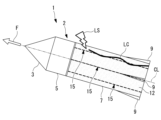
- FIG. 1 is a side view showing a rocket according to a first embodiment of the present disclosure.
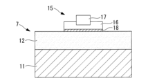
- FIG. 2 is an enlarged cross-sectional view of a portion of the rocket of FIG. 1.
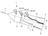
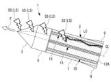
- FIG. 11 is a side view showing a rocket according to a second embodiment of the present disclosure.
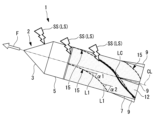
- FIG. 11 is a side view showing a rocket according to a third embodiment of the present disclosure.
- FIG. 11 is a side view showing a rocket according to a fourth embodiment of the present disclosure.
- FIG. 6 is a side view showing a modified example of FIG. 5 .
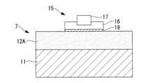
- FIG. 11 is a partially enlarged cross-sectional view of a rocket according to a fifth embodiment of the present disclosure.
- FIG. 8 is a side view of the rocket of FIG. FIG.
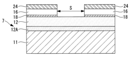
- FIG. 13 is a partially enlarged cross-sectional view showing the spacing of the SDS.
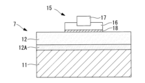
- FIG. 8 is a partially enlarged cross-sectional view showing a modified example of FIG. 7 .
- FIG. 13 is a side view showing a rocket according to the sixth embodiment of the present disclosure.
- FIG. 12 is an enlarged cross-sectional view of a portion of the rocket of FIG.
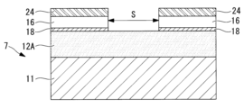
- FIG. 13 is a partially enlarged cross-sectional view showing a modified example of FIG. 12 .
- a rocket 1 equipped with a lightning-resistant structure according to this embodiment is shown in Fig. 1.
- a body 2 of the rocket 1 is mainly made of CFRP (Carbon Fiber Reinforced Plastics).
- the rocket 1's body 2 comprises, in order from the front, i.e., from the direction of travel F, a tip section 3, a forward section (torso) 5, and a rear section 7.
- the tip section 3 is a tapered cone having a central axis CL.
- the forward section 5 is cylindrical and has a common central axis CL.
- the rear section 7 is cylindrical and has a common central axis CL.
- the dimension of the rear section 7 in the direction of the central axis CL i.e., in the longitudinal direction, is greater than that of the forward section 5.
- a number of (e.g., four) tail fins 9 are attached to the rear end of the rear section 7.
- the forward section 5 and rear section 7 are equipped with rocket engines (propulsion devices), separation devices, communication devices, steering devices, and attitude control devices.
- the rear fuselage section 7 has a lightning-resistant structure. Specifically, as shown in FIG. 2, it has a first layer 11 made of CFRP and a second layer 12 that is provided to cover the outer surface of the first layer 11.
- the first layer 11 forms the main shape of the rear fuselage 7 and is cylindrical.
- the CFRP that forms the first layer 11 provides a certain strength to the aircraft.
- the second layer 12 is formed to cover the entire circumference of the first layer 11 and is cylindrical.
- the second layer 12 is made of a dielectric material, and for example, a resin-based paint (such as a heat-resistant paint) is used. Instead of paint, a porous, lightweight thermal insulator (such as cork) that contains a large amount of gas such as air can also be used.
- the thickness of the second layer 12 is, for example, about several mm, and is 2.5 mm or more, preferably 3 mm or more.
- a segmented diverter strip (hereinafter referred to as "SDS") 15 is provided on the outer surface of the second layer 12.
- the SDS 15 has a structure in which a number of metal plates (metal pieces) 17 are fixed onto insulating tape 16, which is an electrical insulator.
- the metal plates 17 are, for example, thin pieces of gold-plated copper.
- the insulating tape 16 is, for example, a polyimide tape.
- the insulating tape 16 is fixed to the second layer 12 using an adhesive 18.
- an adhesive having a heat resistance of about 260°C is selected as the adhesive 18.
- the multiple metal plates (metal pieces) 17 of the SDS 15 are arranged in a line from the front end to the rear end of the SDS 15 in the traveling direction with a predetermined small interval (gap) between each other.
- the SDS 15 is provided in a straight line parallel to the longitudinal direction (direction of the central axis CL) of the rear fuselage section 7.
- Multiple SDSs 15 are provided at predetermined intervals (spaces) in the circumferential direction of the rear fuselage section 7.
- the lightning-resistant structure of the rocket 1 configured as above functions as follows.
- the principle of how lightning strikes an aircraft is detailed in 3.4 Aircraft Lightning Strike Mechanisms in the above-mentioned non-patent document 1, and the following description is based on that theory.
- the first return lightning stroke directly strikes the conductive SDS 15, causing a lightning strike LS, or a creeping discharge occurs on the outer surface from the conductive SDS 15 to the second layer 12 toward the precursor discharge, connecting with it and causing a lightning strike LS, thereby forming a path for the lightning current LC on the SDS 15.
- a sufficient voltage is generated between each metal plate 17 of the SDS 15, causing insulation breakdown not only in the gap but also on the metal plate 17, forming a plasma channel in the atmosphere surrounding the SDS 15 and allowing the lightning current to flow.
- the lightning current guided by the SDS 15 is conducted to the rear side of the rocket 1 and discharged to the clouds or ground surface on the opposite side through the path of the precursor discharge on the opposite side.
- the weight of the rocket 1 can be reduced by constructing the rear body 7 with the first layer 11 using CFRP.
- the CFRP of the first layer 11 is conductive, but the second layer 12 made of a dielectric material is provided to cover the outer surface of the first layer 11.
- the lightning current generated by lightning strike can be collected by providing SDS 15 on the outer surface of the second layer 12.
- the SDS 15 is linear and extends in the longitudinal direction of the rear body 7, and multiple SDS 15 are provided at predetermined intervals around the circumference of the rear body 7, so that the lightning current can be effectively collected and conducted.
- the use of SDS 15 allows lightning current to be conducted effectively.
- the second layer 12 made of a dielectric is provided between the first layer 11 made of CFRP, sufficient electric field strength is generated in the gap between the metal plates 17, causing dielectric breakdown, and effectively demonstrating the function of the SDS.
- the dielectric breakdown path generated in the atmosphere by SDS 15 the path of the large lightning current LC of the lightning stroke LS, the lightning stroke LS can be received and the lightning current LC can be conducted without damaging the conductive layer of the first layer 11 or the dielectric of the second layer 12.
- the SDS 15 is arranged to have a spiral shape. Specifically, the SDS 15 is arranged at a predetermined oblique angle ⁇ with respect to the longitudinal axis L1, which is parallel to the longitudinal direction of the rear fuselage section 7. This oblique angle ⁇ is constant along the longitudinal direction of the rear fuselage section 7.
- the effects of the present embodiment described above are as follows.
- the lightning LS reaches multiple positions on the rocket 1's body in the form of a swept stroke SS. Since the rocket 1 moves at high speed relative to the position where the lightning LS occurs, it is considered that the swept stroke SS reaches multiple positions behind the direction in which the rocket 1 moves, that is, along the longitudinal direction of the body. Therefore, the SDS 15 is arranged at a predetermined oblique angle ⁇ with respect to the longitudinal axis L1 parallel to the longitudinal direction of the rear body 7. As a result, the SDS 15 is arranged in a spiral shape, increasing the probability that the SDS 15 will be located at the position where the swept stroke SS will reach. This allows the interval between adjacent SDS 15 to be widened.
- the diagonal angle ⁇ of the SDS 15 was constant in the longitudinal direction of the rear torso section 7, but in this embodiment, the diagonal angle is made to change in the longitudinal direction of the rear torso section 7.
- the diagonal angle ⁇ 2 on the rear side of the rear torso section 7 (the right side in the figure) is made larger than the diagonal angle ⁇ 1 on the front side ( ⁇ 1 ⁇ 2). In other words, the diagonal angle is made to gradually increase toward the rear side of the rear torso section 7.
- the effects of the present embodiment described above are as follows.
- the oblique angle of the SDS 15 coincides with the rotation angle of the rocket 1
- the SDS 15 may not be located at the target position of the sweep torpedo strike SS. Therefore, by changing the oblique angle of the SDS 15 in the longitudinal direction, the probability that the SDS 15 will be located at the target position of the sweep torpedo strike SS can be increased.
- the oblique angle gradually increases toward the rear of the rear fuselage section 7.
- the oblique angle may gradually decrease, or may change discontinuously so that the SDS 15 forms a broken line.
- an attraction SDS (lightning attraction section) 20 is provided between the SDS 15 and the tip 1a of the rocket 1.
- the attraction SDS 20 attracts lightning strikes to the SDS 15.
- the attraction SDS 20 is provided in the forward section 5 in correspondence with each SDS 15.
- the attraction SDS 20 may be provided up to the tip 3.
- the cross-sectional shape of the forward section 5 (and tip 3) is configured as shown in Fig. 2 as described in the first embodiment.
- the rear end of the attraction SDS 20 is connected to the front end of the SDS 15 , and the front end of the attraction SDS 20 faces the tip 1 a of the rocket 1 .
- the effects of the present embodiment described above are as follows.
- the stepped leader is likely to occur near the tip 1a of the rocket 1.
- the first return stroke and the swept stroke that follow the stepped leader are attracted by the attraction SDS 20. This allows the subsequent swept stroke SS to reach the rear SDS 15 with a high probability.
- a metal fin 22 may be provided as a lightning attractor instead of the SDS 20 for attracting lightning.
- the forward body section 5 and the tip section 3 may be made of metal.
- a wing shape may be used instead of a fin shape.
- the breakdown voltage of the second layer 12A in this embodiment is higher than the breakdown voltage of the first layer 11.
- Specific examples of materials with a high breakdown voltage include Teflon (registered trademark), polyimide, meta-aramid fiber, and GFRP (Glass Fiber Reinforced Plastic).
- the circumferential spacing S of the SDS 15 is determined based on the relationship between the dielectric breakdown voltage of the second layer 12A, which is an electrical insulator, and the creeping discharge voltage. Specifically, it is determined so that the creeping discharge voltage is less than the dielectric breakdown voltage. In this case, the spacing S is set so that the creeping discharge distance is 1/2.
- a second layer 12A having a high breakdown voltage of this embodiment may be provided below the second layer 12 described in the first embodiment.
- the breakdown voltage of the second layer 12A of the present embodiment is higher than the breakdown voltage of the first layer 11.
- Specific examples of materials having a high breakdown voltage include Teflon (registered trademark), polyimide, meta-aramid fiber, and GFRP (Glass Fiber Reinforced Plastic).
- a metal mesh 24 is provided on the insulating tape 16. Note that instead of the metal mesh, a metal film or a metal rod may be used.
- the effects of the present embodiment described above are as follows.
- the metal mesh 24 as the conductive layer, a lightning-resistant structure can be easily constructed.
- these conductive layers it is possible to reduce the penetration of the electromagnetic field into the rocket interior and reduce lightning noise (lightning indirect effect) on the internal electric circuits. 11, even if lightning strikes the second layer 12A between the metal meshes 24 instead of striking the metal meshes 24, the breakdown voltage of the second layer 12A is high, so that the second layer 12A does not break down, and a creeping discharge occurs toward the metal mesh 24, leading to the lightning current being conducted to the metal mesh 24. At this time, no significant damage is caused to the portion of the second layer 12A where the creeping discharge occurs.
- the circumferential spacing S of the metal mesh 24 is determined based on the relationship between the dielectric breakdown voltage of the second layer 12A, which is an electrical insulator, and the creeping discharge voltage. Specifically, it is determined so that the creeping discharge voltage is less than the dielectric breakdown voltage. In this case, the spacing S is set so that the creeping discharge distance is 1/2.
- a second layer 12A having a high breakdown voltage of this embodiment may be provided below the second layer 12 described in the first embodiment.
- the lightning-resistant structure of the rocket (1) comprises a first layer (11) which constitutes the body (7) of the rocket and is made of CFRP, a second layer (12) which is a dielectric and is provided so as to cover the outer surface of the first layer, and a conductive layer (15) which is a conductor and is provided on the outer surface of the second layer, the conductive layer being linear and extending in the longitudinal direction of the body, and multiple conductive layers are provided at predetermined intervals around the circumference of the body.
- the rocket's body can be made lighter by being constructed with a first layer made of CFRP (Carbon Fiber Reinforced Plastics).
- the first layer of CFRP is conductive, but a second layer made of a dielectric material is provided to cover the outer surface of the first layer. This allows the first layer to be electrically insulated and protected by the second layer.
- a conductive layer on the outer surface of the second layer, lightning current generated by lightning strike can be collected in the conductive layer.
- the conductive layer is linear and extends in the longitudinal direction of the body, and multiple conductive layers are provided at predetermined intervals around the circumference of the body, so that lightning current can be effectively collected and conducted.
- linear means that the conductive layers are arranged along an imaginary line, and includes not only a continuous line, but also multiple conductive layers (metal pieces) arranged linearly with tiny gaps between them, such as in a segmented diverter strip.
- a rocket refers to a flying vehicle that uses a liquid or solid rocket engine as a propulsion device.
- the conductive layer is a segmented diverter strip (15) in which metal pieces are arranged linearly at predetermined intervals.
- SDS segmented diverter strip
- metal pieces are arranged linearly at a certain interval as a conductive layer
- the second layer made of a dielectric is provided between the first layer made of CFRP, sufficient electric field strength is generated in the gap between each metal piece, causing dielectric breakdown, and the function of the SDS can be effectively demonstrated.
- the lightning current conducts through the plasma path in the atmosphere and is discharged from the precursor discharge path on the opposite side, so that the CFRP of the first layer and the dielectric of the second layer are not damaged.
- the second layer which is a dielectric
- the thickness of the second layer made of a dielectric material is, for example, about several mm, and is 2.5 mm or more, and preferably 3 mm or more.
- the lightning-resistant structure of a rocket according to the third aspect of the present disclosure is the second aspect, in which the segmented diverter strips are arranged at a predetermined oblique angle with respect to a longitudinal axis parallel to the longitudinal direction of the body.
- the lightning-resistant structure of the rocket according to the fourth aspect of the present disclosure is the third aspect, in which the inclination angle changes in the longitudinal direction of the body.
- the diagonal angle of the SDS is changed along the length of the body.
- the SDS is made to have a spiral shape with a varying diagonal angle along the length.
- the SDS may not be located at the target position for the sweep torpedo. Therefore, by changing the diagonal angle of the SDS along the length, the probability that the SDS will be located at the target position for the sweep torpedo can be increased.
- the lightning-resistant structure of the rocket according to the fifth aspect of the present disclosure is any one of the second to fourth aspects, and includes a lightning attraction section (20) that is provided between the segmented diverter strip and the tip of the rocket and attracts lightning strikes to the segmented diverter strip.
- a lightning attraction section is provided between the segmented diverter strip and the tip of the rocket, which can attract the first return stroke and the swept stroke that follow the stepped leader, increasing the probability that the subsequent swept stroke will reach the rear SDS.
- the lightning attracting portion may be a segmented diverter strip, or may be a metal fin or wing.
- the lightning-resistant structure of the rocket according to the sixth aspect of the present disclosure is such that in any of the first to fifth aspects, the breakdown voltage of the second layer is higher than the breakdown voltage of the first layer.
- the breakdown voltage of the second layer is higher than that of the first layer, so the second layer does not break down and a creeping discharge occurs toward the SDS, leading to the lightning current being conducted to the SDS. At this time, no significant damage occurs to the part of the second layer where the creeping discharge occurs, or to the lightning current conducting part of the SDS.
- materials having a high dielectric breakdown voltage include Teflon (registered trademark), polyimide, meta-aramid fiber, GFRP (Glass Fiber Reinforced Plastic), etc.
- the second layer may be made of a material having a high dielectric breakdown voltage, or a material having a high dielectric breakdown voltage may be used as a part of the second layer.
- the seventh aspect of the present disclosure relates to a lightning-resistant structure for a rocket in the first aspect, in which the conductive layer is a metal mesh, a metal film, or a metal rod, and the breakdown voltage of the second layer is higher than the breakdown voltage of the first layer.
- the conductive layer can be easily constructed by using a metal mesh, metal film, or metal rod, and can also reduce the penetration of electromagnetic fields into the rocket interior and the lightning indirect effect on the internal electrical circuits. Even if lightning strikes the second layer between the conductive layers instead of the SDS, the breakdown voltage of the second layer is higher than that of the first layer, so the second layer does not break down and a creeping discharge occurs toward the conductive layer, leading to the lightning current being conducted to the conductive layer. At this time, no significant damage occurs to the part of the second layer where the creeping discharge occurs.
- the rocket according to the first aspect of the present disclosure has the lightning-resistant structure of any one of the rockets according to the first to seventh aspects.
Landscapes
- Engineering & Computer Science (AREA)
- Aviation & Aerospace Engineering (AREA)
- Remote Sensing (AREA)
- Health & Medical Sciences (AREA)
- Critical Care (AREA)
- Emergency Medicine (AREA)
- General Health & Medical Sciences (AREA)
- Elimination Of Static Electricity (AREA)
Abstract
被雷して発生した雷電流を効果的に散逸させることができるロケットの耐雷構造を提供する。ロケット(1)の耐雷構造は、ロケット(1)の後胴部(7)を構成するとともにCFRPとされた第1層と、第1層の外表面を覆うように設けられ、誘電体とされた第2層(12)と、第2層(12)の外表面に設けられたSDS(15)と、を備え、SDS(15)は、後胴部(7)の長手方向に延在する線状とされ、後胴部(7)の周方向に所定間隔をおいて複数設けられている。
Description
本開示は、ロケットの耐雷構造及びこれを備えたロケットに関するものである。ここでロケットとは、液体または固体ロケットエンジンを推進装置とする飛行体と意味する。
雷によって機体に雷撃を受ける場合がある。機体が金属の場合、導電性を有するため特別な耐雷構造は不要である。これに対して、機体がCFRP(Carbon Fiber Reinforced Plastics:炭素繊維強化プラスチック)またはGFRP(Glass Fiber Reinforced Plastics:ガラス繊維強化プラスチック)等の複合材料の場合、金属のような高い導電性を有していないため、耐雷構造が要求される。例えば航空機の場合、機体の外表面に銅またはアルミなどの金属のメッシュまたは金属フィルム(以下「金属メッシュ等」という。)を採用することで、雷電流を分散あるいは電流の影響を受けにくい金属部材等へ導電させ、金属メッシュ等の下に配置された複合材料を保護することが提案されている(例えば特許文献1及び2)。
また、航空機の耐雷構造としてダイバーターストリップが用いられることがある。ダイバーターストリップには、通常の金属棒のタイプと、セグメンテッド・ダイバーター・ストリップ(Segmented Diverter Strip)がある(特許文献3及び4)。しかし、ダイバーターストリップは電気絶縁物の構造に対してしか機能しない。
Franklin A.Fisher and J.Anderson Plumer,DOT/FAA/TC-22/11,Published by Federal Aviation Administration,U.S.Department of Transportation,Nov.2022,"Lightning Protection of Aircraft Handbook"
しかし、ロケットは、航空機とは異なる機体構造を有しており、耐雷構造として航空機とは異なる検討が必要である。例えば、機体構造の主たる材料としてGFRPよりも軽く強度が大きいCFRPとした場合、CFRPは導電性を有するため耐雷構造として金属メッシュ等を用いたとしても、金属メッシュ等が被雷により破損、雷電流により溶融蒸発あるいは高温になって、継続する雷電流によりCFRPにダメージを与える恐れがある。特にロケットへの適用では、耐熱塗装の損傷が発生する恐れがある。また、ロケットの速度が増加し、空力加熱によって金属メッシュ等が高温になって行くと、ある時点で接着層の接着力が低下したり、金属メッシュ等が溶融して剥がれ落ちることが考えられる。そして、その際にうまく剥がれずに、機体の外面に損傷や溶融を発生させたり、剥離部が機体の後方部に衝突し許容できない損傷を起こす恐れがある。
また、セグメンテッド・ダイバーター・ストリップを用いる場合には、導電性を有するCFRP上に取り付けたとしても、ダイバーターストリップのギャップ間に発生する電界が不十分で、プラズマが発生せず、雷電流を流すプラズマチャネルが発生しないおそれがある。
本開示は、このような事情に鑑みてなされたものであって、被雷して発生した雷電流を効果的に散逸させることができるロケットの耐雷構造及びこれを備えたロケットを提供することを目的とする。
本開示の一態様に係るロケットの耐雷構造は、ロケットの胴部を構成するとともにCFRPとされた第1層と、前記第1層の外表面を覆うように設けられ、誘電体とされた第2層と、前記第2層の外表面に設けられ、導電体とされた導電層と、を備え、前記導電層は、前記胴部の長手方向に延在する線状とされ、前記胴部の周方向に所定間隔をおいて複数設けられている。
本開示の一態様に係るロケットは、上記のロケットの耐雷構造を備えている。
被雷して発生した雷電流を効果的に導電させることができる。
以下に、本開示に係る実施形態について、図面を参照して説明する。
[第1実施形態]
以下、本開示の第1実施形態について説明する。
図1には本実施形態に係る耐雷構造を備えたロケット1が示されている。ロケット1の機体2は、主としてCFRP(Carbon Fiber Reinforced Plastics:炭素繊維強化プラスチック)で構成されている。
[第1実施形態]
以下、本開示の第1実施形態について説明する。
図1には本実施形態に係る耐雷構造を備えたロケット1が示されている。ロケット1の機体2は、主としてCFRP(Carbon Fiber Reinforced Plastics:炭素繊維強化プラスチック)で構成されている。
ロケット1の機体2は、前方すなわち進行方向F側から順に、先端部3と、前胴部(胴部)5と、後胴部7とを備えている。先端部3は、中心軸線CLを有し先細とされた円錐形とされている。前胴部5は、共通の中心軸線CLを有し円筒形とされている。後胴部7は、共通の中心軸線CLを有し円筒形とされている。後胴部7の中心軸線CL方向すなわち長手方向の寸法は、前胴部5よりも大きい。後胴部7の後端には、複数の(例えば4つの)尾翼9が取り付けられている。図示していないが、前胴部5および後胴部7にはロケットエンジン(推進装置)、切り離し装置、通信装置、操舵装置や姿勢制御装置が設けられている。
後胴部7は、耐雷構造が施されている。具体的には、図2に示すように、CFRPで構成された第1層11と、第1層11の外表面を覆うように設けられた第2層12とを備えている。
第1層11は、後胴部7の主たる形状を構成し、円筒形とされている。第1層11を構成するCFRPによって機体の所定の強度を負担させる。
第2層12は、第1層11の全周を覆うように形成され、円筒形とされている。第2層12は、誘電体で構成されており、例えば樹脂系の塗装(耐熱塗装など)が用いられる。塗装に代えて、空気などの気体を多く含む多孔質で軽量の熱的絶縁物(コルクなど)を用いることもできる。第2層12の厚さは、例えば、数mm程度とされ、2.5mm以上、好ましくは3mm以上とされる。
第2層12の外表面には、セグメンテッド・ダイバーター・ストリップ(Segmented Diverter Strip:以下「SDS」という。)15が設けられている。SDS15は、電気絶縁体とされた絶縁テープ16上に複数の金属板(金属片)17が固定された構造とされている。金属板17は、例えば金メッキされた銅の薄片が用いられる。絶縁テープ16としては、例えばポリイミドテープが用いられる。絶縁テープ16は、第2層12に対して接着剤18を用いて固定させる。接着剤18としては、例えば260℃程度の耐熱性を有するものが選定される。
SDS15の複数の金属板(金属片)17は、互いに所定の微小な間隔(ギャップ)をおいて、SDS15の進行方向前端部から後端部まで線状に並べられている。SDS15は、図1に示すように、後胴部7の長手方向(中心軸線CL方向)に平行に直線状に設けられている。SDS15は、後胴部7の周方向に所定の間隔(スペース)をおいて複数設けられている。
上記構成のロケット1の耐雷構造は以下のように機能する。なお、飛行体への被雷の原理は上記の非特許文献1の3.4 Aircraft Lightning Strike Mechanismsに詳述されており、以下はその理論にもとづき記載している。
ロケット1の後胴部7のCFRPを主構造とする部分への被雷シナリオには大きく分けて2つが考えられる。それは、(1)第1帰還雷撃(First Return Stroke)が着雷するケースと、(2)掃引雷撃(Swept Stroke)が着雷するケースである。
どちらの場合も、ロケット1が雷雲と地表面、雷雲と雷雲、あるいは、雷雲の内部に入り、ロケット1の周囲に強い電界が生じると、ロケットの先端部や後端部の電界が集中する部位から前駆放電(Stepped Leader)が発生し、電界の方向に沿って進展していく。この時、前駆放電の大気中の位置はほとんど動かないため、ロケット1の飛行による機体の移動により、ロケット1の先端1a付近で発生した前駆放電の位置はロケット1の後方に相対的に移動していく。一方、ロケット1の後端部付近で発生した前駆放電は同じ部位に接続し続ける(Hang on)。雲の方向に延びていった前駆放電が雷雲からの前駆放電と結合(Junction)し、反対方向に延びていった前駆放電が反対側の雲または地表面からの前駆放電と結合すると、回路が繋がることで第1帰還雷撃LSが発生する。
一方、この過程と同時並行的に、SDS15の複数の金属板17の間に設けられた微小な間隔(ギャップ)の絶縁テープ16上に電界が発生するので、ある時点で絶縁破壊(沿面放電)が発生する。このSDS15すべてのギャップに絶縁破壊が生じると、SDS15は導電状態となる。この際に導電性を有する第1層11はSDS15から第2層12によって離隔されているため、各金属板17間のギャップに電界強度が発生することへの影響を抑えることができる。
上記(1)の場合、前駆放電が後胴部7に到達すると、直接第1帰還雷撃が導電状態のSDS15に雷撃LSを起こすか、前駆放電に向けて外表面上を沿面放電が導電状態のSDS15から第2層12に発生して結合することにより雷撃LSを起こし、それにより雷電流LCの経路がSDS15上に形成される。具体的には、SDS15の各金属板17間に十分な電圧が発生し、ギャップだけでなく金属板17上にも絶縁破壊が生じ、SDS15上の周辺の大気中にプラズマチャネルが形成されて雷電流が流れる。このようにしてSDS15によって導かれた雷電流はロケット1の後部側へ導電されて反対側の前駆放電の経路を通じて反対側の雲や地表面に放電される。
上記(2)の場合、掃引雷撃(Swept Stroke)が後胴部7に到達すると、掃引雷撃による雷撃LSから導通状態のSDS15に向けて沿面放電が発生し、上記(1)と同様に雷撃LSを起こし雷電流LCが形成される。さらにそれ以降も上記(1)と同様のメカニズムで雷電流LCが放電される。なお、図1において雷電流LCの線はSDS15の上部に複数の曲部を設けて描画しているが、実際にはSDS15の上部をある程度の太さでほぼ直線的な経路で導電すると考えられる。これは以下の実施形態でも同様である。
以上説明した本実施形態の作用効果は以下の通りである。
ロケット1の後胴部7としてCFRPを用いた第1層11で構成することによって軽量化することができる。第1層11のCFRPは導電性を有するが、第1層11の外表面を覆うように誘電体とされた第2層12を設けることとした。そして、第2層12の外表面にSDS15を設けることで被雷して発生した雷電流を集電することができる。SDS15は後胴部7の長手方向に延在する線状とされて後胴部7の周方向に所定間隔をおいて複数設けられているので、効果的に雷電流を集電し、導電させることができる。
SDS15を用いることで、有効に雷電流を導電させることができる。誘電体とされた第2層12がCFRPとされた第1層11との間に設けられているので、各金属板17間のギャップに十分な電界強度が発生し、絶縁破壊が生じ、SDSの機能を有効に発揮できる。SDS15が大気中に発生させる絶縁破壊経路を雷撃LSの大電流の雷電流LCの経路とすることで、第1層11の導電層や第2層12の誘電体を損傷させることなく雷撃LSを受け、雷電流LCを導電することができる。
ロケット1の後胴部7としてCFRPを用いた第1層11で構成することによって軽量化することができる。第1層11のCFRPは導電性を有するが、第1層11の外表面を覆うように誘電体とされた第2層12を設けることとした。そして、第2層12の外表面にSDS15を設けることで被雷して発生した雷電流を集電することができる。SDS15は後胴部7の長手方向に延在する線状とされて後胴部7の周方向に所定間隔をおいて複数設けられているので、効果的に雷電流を集電し、導電させることができる。
SDS15を用いることで、有効に雷電流を導電させることができる。誘電体とされた第2層12がCFRPとされた第1層11との間に設けられているので、各金属板17間のギャップに十分な電界強度が発生し、絶縁破壊が生じ、SDSの機能を有効に発揮できる。SDS15が大気中に発生させる絶縁破壊経路を雷撃LSの大電流の雷電流LCの経路とすることで、第1層11の導電層や第2層12の誘電体を損傷させることなく雷撃LSを受け、雷電流LCを導電することができる。
[第2実施形態]
次に、本開示の第2実施形態について説明する。本実施形態は、第1実施形態に対してSDS15の配置が異なり、その他については同様である。したがって、第1実施形態と共通する構成については同一符号を付しその説明を省略する。
次に、本開示の第2実施形態について説明する。本実施形態は、第1実施形態に対してSDS15の配置が異なり、その他については同様である。したがって、第1実施形態と共通する構成については同一符号を付しその説明を省略する。
図3に示すように、SDS15が螺旋形状となるように設けられている。具体的には、SDS15は、後胴部7の長手方向に平行な長手軸線L1に対して所定の斜め角度αを有して配置されている。この斜め角度αは、後胴部7の長手方向にわたって一定とされている。
以上説明した本実施形態の作用効果は以下の通りである。
雷撃LSは、掃引雷撃(swept stroke)SSの形式でロケット1の機体の複数位置に到達する。雷撃LSの発生位置に対してロケット1が高速で進行するので、掃引雷撃SSの到達位置はロケット1が進行する方向に対し後方、すなわち機体の長手方向に沿って複数個所に到達すると考えられる。そこで、SDS15を後胴部7の長手方向に平行な長手軸線L1に対して所定の斜め角度αを有して配置することとした。これにより、SDS15は螺旋形状に配置され、掃引雷撃SSの到達位置にSDS15が位置する確率を高めることとした。これにより、隣り合うSDS15の間隔を広げることができる。
雷撃LSは、掃引雷撃(swept stroke)SSの形式でロケット1の機体の複数位置に到達する。雷撃LSの発生位置に対してロケット1が高速で進行するので、掃引雷撃SSの到達位置はロケット1が進行する方向に対し後方、すなわち機体の長手方向に沿って複数個所に到達すると考えられる。そこで、SDS15を後胴部7の長手方向に平行な長手軸線L1に対して所定の斜め角度αを有して配置することとした。これにより、SDS15は螺旋形状に配置され、掃引雷撃SSの到達位置にSDS15が位置する確率を高めることとした。これにより、隣り合うSDS15の間隔を広げることができる。
[第3実施形態]
次に、本開示の第3実施形態について説明する。本実施形態は、第2実施形態に対してSDS15の配置が異なり、その他については同様である。したがって、第1実施形態及び第2実施形態と共通する構成については同一符号を付しその説明を省略する。
次に、本開示の第3実施形態について説明する。本実施形態は、第2実施形態に対してSDS15の配置が異なり、その他については同様である。したがって、第1実施形態及び第2実施形態と共通する構成については同一符号を付しその説明を省略する。
第2実施形態ではSDS15の斜め角度αが後胴部7の長手方向に一定であるとしたが、本実施形態では、斜め角度を後胴部7の長手方向において変化するようにした。図4に示すように、後胴部7の後側(同図において右側)の斜め角度α2を、前側の斜め角度α1よりも大きくした(α1<α2)。すなわち、後胴部7の後側に行くに従い斜め角度を漸次増大するようにした。
以上説明した本実施形態の作用効果は以下の通りである。
ロケット1が中心軸線CL回りに回転して進行する場合、SDS15の斜め角度とロケット1の回転角度とが一致すると、掃引雷撃SSの到達位置にSDS15が位置しない場合が生じうる。そこで、SDS15の斜め角度を長手方向で変化させることで、掃引雷撃SSの到達位置にSDS15が位置する確率を高めることができる。
なお、図4に示した実施形態では斜め角度が後胴部7の後側に行くに従い漸次増大するようにしたが、これに限定されるものではなく、漸次減少するようにしても良いし、SDS15が折れ線状となるように不連続に変化させても良い。
ロケット1が中心軸線CL回りに回転して進行する場合、SDS15の斜め角度とロケット1の回転角度とが一致すると、掃引雷撃SSの到達位置にSDS15が位置しない場合が生じうる。そこで、SDS15の斜め角度を長手方向で変化させることで、掃引雷撃SSの到達位置にSDS15が位置する確率を高めることができる。
なお、図4に示した実施形態では斜め角度が後胴部7の後側に行くに従い漸次増大するようにしたが、これに限定されるものではなく、漸次減少するようにしても良いし、SDS15が折れ線状となるように不連続に変化させても良い。
[第4実施形態]
次に、本開示の第4実施形態について説明する。本実施形態は、第1実施形態に対して構成を付加した点で相違し、その他については同様である。したがって、第1実施形態と共通する構成については同一符号を付しその説明を省略する。
次に、本開示の第4実施形態について説明する。本実施形態は、第1実施形態に対して構成を付加した点で相違し、その他については同様である。したがって、第1実施形態と共通する構成については同一符号を付しその説明を省略する。
図5に示すように、SDS15とロケット1の先端1aとの間に、誘引用SDS(着雷誘引部)20が設けられている。誘引用SDS20は、SDS15への着雷を誘引する。誘引用SDS20は、各SDS15に対応して、前胴部5に設けられている。なお、誘引用SDS20は、先端部3にまで設けられていても良い。この場合、前胴部5(及び先端部3)の横断面形状は、第1実施形態で説明したように図2のような構成とされている。
誘引用SDS20の後端は、SDS15の前端に接続され、誘引用SDS20の前端はロケット1の先端1aの方向を向いている。
誘引用SDS20の後端は、SDS15の前端に接続され、誘引用SDS20の前端はロケット1の先端1aの方向を向いている。
以上説明した本実施形態の作用効果は以下の通りである。
前駆放電(Stepped Leader)は、ロケット1の先端1a付近に発生しやすい。そして、前駆放電に続いて生じる第1帰還雷撃(First Return Stroke)及び掃引雷撃(Swept Stroke)を誘引用SDS20によって誘引することとした。これにより、その後に引き続き起きる掃引雷撃SSが後方のSDS15に高い確率で到達させることができる。
前駆放電(Stepped Leader)は、ロケット1の先端1a付近に発生しやすい。そして、前駆放電に続いて生じる第1帰還雷撃(First Return Stroke)及び掃引雷撃(Swept Stroke)を誘引用SDS20によって誘引することとした。これにより、その後に引き続き起きる掃引雷撃SSが後方のSDS15に高い確率で到達させることができる。
なお、図6に示すように、着雷誘引部として、誘引用SDS20に代えて金属製のフィン22を設けても良い。この場合、前胴部5及び先端部3は金属製とされていても良い。また、フィン形状ではなくウィング形状としても良い。
[第5実施形態]
次に、本開示の第5実施形態について説明する。本実施形態は、第1実施形態に対して第2層を異なる構成とした点で相違し、その他については同様である。したがって、第1実施形態と共通する構成については同一符号を付しその説明を省略する。
次に、本開示の第5実施形態について説明する。本実施形態は、第1実施形態に対して第2層を異なる構成とした点で相違し、その他については同様である。したがって、第1実施形態と共通する構成については同一符号を付しその説明を省略する。
図7に示すように、本実施形態の第2層12Aの絶縁破壊電圧は、第1層11の絶縁破壊電圧よりも高い。絶縁破壊電圧が高い材料としては、具体的には、テフロン(登録商標)、ポリイミド、メタアラミド繊維、GFRP(Glass Fiber Reinforced Plastic:ガラス繊維強化プラスチック)などを用いることができる。
以上説明した本実施形態の作用効果は以下の通りである。
図8に示すように、SDS15に着雷せずにSDS15の間の第2層12Aに着雷した場合であっても、第2層12Aの絶縁破壊電圧が高いので、第2層12Aが絶縁破壊することなく、SDS15に向けて沿面放電が発生し、SDS15に雷電流が導かれる。このとき、第2層12Aの沿面放電の発生部分、および、SDS15の雷電流導電部分に大きな損傷は発生しない。
図8に示すように、SDS15に着雷せずにSDS15の間の第2層12Aに着雷した場合であっても、第2層12Aの絶縁破壊電圧が高いので、第2層12Aが絶縁破壊することなく、SDS15に向けて沿面放電が発生し、SDS15に雷電流が導かれる。このとき、第2層12Aの沿面放電の発生部分、および、SDS15の雷電流導電部分に大きな損傷は発生しない。
図9に示すように、SDS15の周方向の間隔Sは、電気絶縁物である第2層12Aの絶縁破壊電圧と沿面放電電圧との関係で決定する。具体的には、沿面放電電圧<絶縁破壊電圧となるように決定する。このとき、沿面放電距離は1/2となるように間隔Sを設定する。
なお、図10に示すように、第1実施形態で説明した第2層12の下方に本実施形態の絶縁破壊電圧が高い第2層12Aを設けるようにしても良い。
[第6実施形態]
次に、本開示の第6実施形態について説明する。本実施形態は、第1実施形態に対してSDS15を用いない点及び第2層を異なる構成とした点で相違し、その他については同様である。したがって、第1実施形態と共通する構成については同一符号を付しその説明を省略する。
次に、本開示の第6実施形態について説明する。本実施形態は、第1実施形態に対してSDS15を用いない点及び第2層を異なる構成とした点で相違し、その他については同様である。したがって、第1実施形態と共通する構成については同一符号を付しその説明を省略する。
図11に示すように、本実施形態の第2層12Aの絶縁破壊電圧は、第1層11の絶縁破壊電圧よりも高い。絶縁破壊電圧が高い材料としては、具体的には、テフロン(登録商標)、ポリイミド、メタアラミド繊維、GFRP(Glass Fiber Reinforced Plastic:ガラス繊維強化プラスチック)などを用いることができる。
第1実施形態のSDS15および金属板17に代えて、金属メッシュ24が絶縁テープ16上に設けられている。なお、金属メッシュに代えて、金属フィルム又は金属棒としても良い。
第1実施形態のSDS15および金属板17に代えて、金属メッシュ24が絶縁テープ16上に設けられている。なお、金属メッシュに代えて、金属フィルム又は金属棒としても良い。
以上説明した本実施形態の作用効果は以下の通りである。
導電層として金属メッシュ24を採用することで、簡便に耐雷構造を構成することができる。また、これらの導電層とすることで、ロケット内部への電磁界の浸透を低減し、内部電気回路への雷ノイズ(Lightning Indirect Effect: 間接雷効果)を低減することもできる。
図11に示すように金属メッシュ24に着雷せずに金属メッシュ24の間の第2層12Aに着雷した場合であっても、第2層12Aの絶縁破壊電圧が高いので、第2層12Aが絶縁破壊することなく、金属メッシュ24に向けて沿面放電が発生し、金属メッシュ24に雷電流が導かれる。このとき、第2層12Aの沿面放電の発生部分に大きな損傷は発生しない。
導電層として金属メッシュ24を採用することで、簡便に耐雷構造を構成することができる。また、これらの導電層とすることで、ロケット内部への電磁界の浸透を低減し、内部電気回路への雷ノイズ(Lightning Indirect Effect: 間接雷効果)を低減することもできる。
図11に示すように金属メッシュ24に着雷せずに金属メッシュ24の間の第2層12Aに着雷した場合であっても、第2層12Aの絶縁破壊電圧が高いので、第2層12Aが絶縁破壊することなく、金属メッシュ24に向けて沿面放電が発生し、金属メッシュ24に雷電流が導かれる。このとき、第2層12Aの沿面放電の発生部分に大きな損傷は発生しない。
図12に示すように、金属メッシュ24の周方向の間隔Sは、電気絶縁物である第2層12Aの絶縁破壊電圧と沿面放電電圧との関係で決定する。具体的には、沿面放電電圧<絶縁破壊電圧となるように決定する。このとき、沿面放電距離は1/2となるように間隔Sを設定する。
なお、図13に示すように、第1実施形態で説明した第2層12の下方に本実施形態の絶縁破壊電圧が高い第2層12Aを設けるようにしても良い。
以上説明した各実施形態に記載のロケットの耐雷構造及びこれを備えたロケットは、例えば以下のように把握される。
本開示の第1態様に係るロケット(1)の耐雷構造は、ロケットの胴部(7)を構成するとともにCFRPとされた第1層(11)と、前記第1層の外表面を覆うように設けられ、誘電体とされた第2層(12)と、前記第2層の外表面に設けられ、導電体とされた導電層(15)と、を備え、前記導電層は、前記胴部の長手方向に延在する線状とされ、前記胴部の周方向に所定間隔をおいて複数設けられている。
ロケットの胴部としてCFRP(Carbon Fiber Reinforced Plastics:炭素繊維強化プラスチック)を用いた第1層で構成することによって軽量化することができる。第1層のCFRPは導電性を有するが、第1層の外表面を覆うように誘電体とされた第2層を設けることとした。これにより、第1層を第2層で電気絶縁して保護することができる。そして、第2層の外表面に導電層を設けることで被雷して発生した雷電流を導電層に集電することができる。導電層は胴部の長手方向に延在する線状とされて胴部の周方向に所定間隔をおいて複数設けられているので、効果的に雷電流を集電し、導電させることができる。
なお、線状とは、導電層が仮想の線に沿って配置されていることを意味し、一連とされた線状だけでなく、セグメンテッド・ダイバーター・ストリップのように微小の間隔(ギャップ)を空けて複数の導電層(金属片)が線状に並べられていることも含む。
また、ロケットとは、液体または固体ロケットエンジンを推進装置とする飛行体と意味する。
なお、線状とは、導電層が仮想の線に沿って配置されていることを意味し、一連とされた線状だけでなく、セグメンテッド・ダイバーター・ストリップのように微小の間隔(ギャップ)を空けて複数の導電層(金属片)が線状に並べられていることも含む。
また、ロケットとは、液体または固体ロケットエンジンを推進装置とする飛行体と意味する。
本開示の第2態様に係るロケットの耐雷構造は、前記第1態様において、前記導電層は、金属片が所定間隔をおいて線状に並べられたセグメンテッド・ダイバーター・ストリップ(15)とされている。
導電層として金属片が所定間隔をおいて線状に並べられたセグメンテッド・ダイバーター・ストリップ(Segmented Diverter Strip:SDS)を用いることで、有効に雷電流を導電させることができる。誘電体とされた第2層がCFRPとされた第1層との間に設けられているので、各金属片間のギャップに十分な電界強度が発生し、絶縁破壊が生じ、SDSの機能を有効に発揮できる。SDSが機能すると、雷電流は大気中のプラズマ経路を導電し反対側の前駆放電経路から放電されるので、第1層のCFRPと第2層の誘電体を損傷させることがない。
誘電体とされた第2層は、例えば、樹脂系の塗装が用いられ、または、空気などの気体を多く含む多孔質で軽量の熱的絶縁物(コルクなど)を用いることができる。さらには、ロケットで空力加熱対策として必要となる耐熱塗料や耐熱物を用いて2つの機能を持たせることもできる。
誘電体とされた第2層の厚さは、例えば、数mm程度とされ、2.5mm以上、好ましくは3mm以上とされる。
誘電体とされた第2層は、例えば、樹脂系の塗装が用いられ、または、空気などの気体を多く含む多孔質で軽量の熱的絶縁物(コルクなど)を用いることができる。さらには、ロケットで空力加熱対策として必要となる耐熱塗料や耐熱物を用いて2つの機能を持たせることもできる。
誘電体とされた第2層の厚さは、例えば、数mm程度とされ、2.5mm以上、好ましくは3mm以上とされる。
本開示の第3態様に係るロケットの耐雷構造は、前記第2態様において、前記セグメンテッド・ダイバーター・ストリップは、前記胴部の長手方向に平行な長手軸線に対して所定の斜め角度を有して配置されている。
雷撃は、掃引雷撃(swept stroke)の形式でロケットの胴部の複数位置に到達する。掃引雷撃に対してロケットが高速で進行するので、掃引雷撃の到達位置はロケットが進行する方向すなわち胴部の長手方向に沿って到達すると考えられる。そこで、SDSを胴部の長手方向に平行な長手軸線に対して所定の斜め角度を有して配置することとした。これにより、SDSは螺旋形状に配置され、掃引雷撃の到達位置にSDSが位置する確率を高めることとした。これにより、隣り合うSDSの間隔を広げることができる。
本開示の第4態様に係るロケットの耐雷構造は、前記第3態様において、前記斜め角度は、前記胴部の長手方向において変化する。
SDSの斜め角度を胴部の長手方向において変化させるようにした。すなわち、SDSを一定の斜め角度とされた螺旋形状とするのではなく、長手方向で斜め角度が変化した螺旋形状となるようにした。例えば、ロケットが中心軸線回りに回転して進行する場合、SDSの斜め角度とロケットの回転角度とが一致すると、掃引雷撃の到達位置にSDSが位置しない場合が生じうる。そこで、SDSの斜め角度を長手方向で変化させることで、掃引雷撃の到達位置にSDSが位置する確率を高めることができる。
本開示の第5態様に係るロケットの耐雷構造は、前記第2態様から前記第4態様のいずれかにおいて、前記セグメンテッド・ダイバーター・ストリップと前記ロケットの先端との間に設けられ、該セグメンテッド・ダイバーター・ストリップへの着雷を誘引する着雷誘引部(20)が設けられている。
セグメンテッド・ダイバーター・ストリップとロケットの先端との間に着雷誘引部を設けることとした。これにより、前駆放電(Stepped Leader)に続いて生じる第1帰還雷撃(First Return Stroke)及び掃引雷撃(Swept Stroke)を誘引できるので、その後に引き続き起きる掃引雷撃が後方のSDSに高い確率で到達させることができる。
着雷誘引部としては、セグメンテッド・ダイバーター・ストリップを用いても良いし、金属製のフィンやウィングを用いても良い。
着雷誘引部としては、セグメンテッド・ダイバーター・ストリップを用いても良いし、金属製のフィンやウィングを用いても良い。
本開示の第6態様に係るロケットの耐雷構造は、前記第1態様から前記第5態様のいずれかにおいて、前記第2層の絶縁破壊電圧は、前記第1層の絶縁破壊電圧よりも高い。
SDSに着雷せずにSDSの間の第2層に着雷した場合であっても、第2層の絶縁破壊電圧が第1層よりも高いので、第2層が絶縁破壊することなく、SDSに向けて沿面放電が発生し、SDSに雷電流が導かれる。このとき、第2層の沿面放電の発生部分、および、SDSの雷電流導電部分に大きな損傷は発生しない。
絶縁破壊電圧が高い材料としては、テフロン(登録商標)、ポリイミド、メタアラミド繊維、GFRP(Glass Fiber Reinforced Plastic:ガラス繊維強化プラスチック)などを用いることができる。絶縁破壊電圧が高い材料で第2層を構成しても良いし、絶縁破壊電圧が高い材料を第2層の一部の層としても良い。
絶縁破壊電圧が高い材料としては、テフロン(登録商標)、ポリイミド、メタアラミド繊維、GFRP(Glass Fiber Reinforced Plastic:ガラス繊維強化プラスチック)などを用いることができる。絶縁破壊電圧が高い材料で第2層を構成しても良いし、絶縁破壊電圧が高い材料を第2層の一部の層としても良い。
本開示の第7態様に係るロケットの耐雷構造は、前記第1態様において、前記導電層は、金属メッシュ、金属フィルム又は金属棒とされ、前記第2層の絶縁破壊電圧は、前記第1層の絶縁破壊電圧よりも高い。
導電層を金属メッシュ、金属フィルム又は金属棒とすることで、簡便に構成することができる。また、これらの導電層とすることで、ロケット内部への電磁界の浸透を低減し、内部電気回路への雷ノイズ(Lightning Indirect Effect: 間接雷効果)を低減することもできる。
SDSに着雷せずに導電層の間の第2層に着雷した場合であっても、第2層の絶縁破壊電圧が第1層よりも高いので、第2層が絶縁破壊することなく、導電層に向けて沿面放電が発生し、導電層に雷電流が導かれる。このとき、第2層の沿面放電の発生部分に大きな損傷は発生しない。
SDSに着雷せずに導電層の間の第2層に着雷した場合であっても、第2層の絶縁破壊電圧が第1層よりも高いので、第2層が絶縁破壊することなく、導電層に向けて沿面放電が発生し、導電層に雷電流が導かれる。このとき、第2層の沿面放電の発生部分に大きな損傷は発生しない。
本開示の第1態様に係るロケットは、前記第1態様から前記第7態様のいずれかのロケットの耐雷構造を備えている。
1 ロケット
1a 先端
2 機体
3 先端部
5 前胴部
7 後胴部(胴部)
9 尾翼
11 第1層
12 第2層
15 SDS(導電層)
16 絶縁テープ
17 金属板(金属片)
18 接着剤
20 誘引用SDS
22 フィン
24 金属メッシュ(導電層)
1a 先端
2 機体
3 先端部
5 前胴部
7 後胴部(胴部)
9 尾翼
11 第1層
12 第2層
15 SDS(導電層)
16 絶縁テープ
17 金属板(金属片)
18 接着剤
20 誘引用SDS
22 フィン
24 金属メッシュ(導電層)
Claims (8)
- ロケットの胴部を構成するとともにCFRPとされた第1層と、
前記第1層の外表面を覆うように設けられ、誘電体とされた第2層と、
前記第2層の外表面に設けられ、導電体とされた導電層と、
を備え、
前記導電層は、前記胴部の長手方向に延在する線状とされ、前記胴部の周方向に所定間隔をおいて複数設けられているロケットの耐雷構造。 - 前記導電層は、金属片が所定間隔をおいて線状に並べられたセグメンテッド・ダイバーター・ストリップとされている請求項1に記載のロケットの耐雷構造。
- 前記セグメンテッド・ダイバーター・ストリップは、前記胴部の長手方向に平行な長手軸線に対して所定の斜め角度を有して配置されている請求項2に記載のロケットの耐雷構造。
- 前記斜め角度は、前記胴部の長手方向において変化する請求項3に記載のロケットの耐雷構造。
- 前記セグメンテッド・ダイバーター・ストリップと前記ロケットの先端との間に設けられ、該セグメンテッド・ダイバーター・ストリップへの着雷を誘引する着雷誘引部が設けられている請求項2又は3に記載のロケットの耐雷構造。
- 前記第2層の絶縁破壊電圧は、前記第1層の絶縁破壊電圧よりも高い請求項2又は3に記載のロケットの耐雷構造。
- 前記導電層は、金属メッシュ、金属フィルム又は金属棒とされ、
前記第2層の絶縁破壊電圧は、前記第1層の絶縁破壊電圧よりも高い請求項1に記載のロケットの耐雷構造。 - 請求項1又は7に記載のロケットの耐雷構造を備えたロケット。
Applications Claiming Priority (2)
| Application Number | Priority Date | Filing Date | Title |
|---|---|---|---|
| JP2023-102030 | 2023-06-21 | ||
| JP2023102030A JP2025002102A (ja) | 2023-06-21 | 2023-06-21 | ロケットの耐雷構造及びこれを備えたロケット |
Publications (1)
| Publication Number | Publication Date |
|---|---|
| WO2024262159A1 true WO2024262159A1 (ja) | 2024-12-26 |
Family
ID=93935525
Family Applications (1)
| Application Number | Title | Priority Date | Filing Date |
|---|---|---|---|
| PCT/JP2024/015988 Ceased WO2024262159A1 (ja) | 2023-06-21 | 2024-04-24 | ロケットの耐雷構造及びこれを備えたロケット |
Country Status (2)
| Country | Link |
|---|---|
| JP (1) | JP2025002102A (ja) |
| WO (1) | WO2024262159A1 (ja) |
Citations (5)
| Publication number | Priority date | Publication date | Assignee | Title |
|---|---|---|---|---|
| US4796153A (en) * | 1987-06-01 | 1989-01-03 | Lightning Diversion Systems | Lightning diversion strips for aircraft |
| US20050041362A1 (en) * | 2003-08-18 | 2005-02-24 | Hall Allen L. | Current diverter strip and methods |
| JP2006219078A (ja) * | 2005-02-14 | 2006-08-24 | Honda Motor Co Ltd | 航空機用複合体及び航空機の複合体構造部の製造方法 |
| JP2012240610A (ja) * | 2011-05-23 | 2012-12-10 | Kaneka Corp | 航空機用構造材料及びその利用 |
| JP2019209699A (ja) * | 2018-05-31 | 2019-12-12 | 株式会社Subaru | 航空機 |
-
2023
- 2023-06-21 JP JP2023102030A patent/JP2025002102A/ja active Pending
-
2024
- 2024-04-24 WO PCT/JP2024/015988 patent/WO2024262159A1/ja not_active Ceased
Patent Citations (5)
| Publication number | Priority date | Publication date | Assignee | Title |
|---|---|---|---|---|
| US4796153A (en) * | 1987-06-01 | 1989-01-03 | Lightning Diversion Systems | Lightning diversion strips for aircraft |
| US20050041362A1 (en) * | 2003-08-18 | 2005-02-24 | Hall Allen L. | Current diverter strip and methods |
| JP2006219078A (ja) * | 2005-02-14 | 2006-08-24 | Honda Motor Co Ltd | 航空機用複合体及び航空機の複合体構造部の製造方法 |
| JP2012240610A (ja) * | 2011-05-23 | 2012-12-10 | Kaneka Corp | 航空機用構造材料及びその利用 |
| JP2019209699A (ja) * | 2018-05-31 | 2019-12-12 | 株式会社Subaru | 航空機 |
Also Published As
| Publication number | Publication date |
|---|---|
| JP2025002102A (ja) | 2025-01-09 |
Similar Documents
| Publication | Publication Date | Title |
|---|---|---|
| CN112055684B (zh) | 除冰系统 | |
| US9702255B2 (en) | Propeller with lightening strike protection | |
| US8462481B2 (en) | Lightning protection system and aircraft comprising such a system | |
| US20090140098A1 (en) | Component with carbon nanotubes | |
| CN104903198B (zh) | 闪电防护装置、闪电敏感结构及制造闪电防护装置的方法 | |
| CN106314800A (zh) | 一种基于等离子体冲击射流的破除冰方法 | |
| US20190382119A1 (en) | Heatable leading-edge apparatus, leading-edge heating system and aircraft comprising them | |
| WO2017192348A1 (en) | Charge control system to reduce risk of an aircraft-initiated lightning strike | |
| CN114104299A (zh) | 超疏水涂层等离子体与石墨烯电热复合防除冰装置及方法 | |
| CN110481805A (zh) | 一种飞机避免雷击方法 | |
| US5263661A (en) | Sonic boom attenuator | |
| CN105000171A (zh) | 飞翼布局飞行器低速失速控制装置及控制方法 | |
| JP2025002102A (ja) | ロケットの耐雷構造及びこれを備えたロケット | |
| RU2495788C2 (ru) | Крыло гиперзвукового летательного аппарата в условиях его аэродинамического нагрева | |
| EP2969769B1 (en) | Lightning protection for vehicles | |
| CN110707410A (zh) | 一种超材料、雷达罩及飞行器 | |
| US3480231A (en) | Lightning protection for aircraft components | |
| EP4338947A1 (en) | Aircraft lightning strike protection | |
| JPS62154499A (ja) | 避雷装置 | |
| CN113148183A (zh) | 等离子体热刀与疏水材料复合式除冰装置及应用 | |
| US20220063821A1 (en) | Ionic propulsion system | |
| KR101681558B1 (ko) | 낙뢰전달기능의 레이돔 체결부재 및 이를 포함하는 레이돔 조립체 | |
| CN119117277A (zh) | 表面对流传热增强型等离子体防除冰装置和方法 | |
| KR20230170458A (ko) | 항공기 방·제빙 시스템 및 이를 제조하는 방법 | |
| JP2019209699A (ja) | 航空機 |
Legal Events
| Date | Code | Title | Description |
|---|---|---|---|
| 121 | Ep: the epo has been informed by wipo that ep was designated in this application |
Ref document number: 24825568 Country of ref document: EP Kind code of ref document: A1 |
|
| NENP | Non-entry into the national phase |
Ref country code: DE |