WO2024261925A1 - 空気調和システム - Google Patents
空気調和システム Download PDFInfo
- Publication number
- WO2024261925A1 WO2024261925A1 PCT/JP2023/023004 JP2023023004W WO2024261925A1 WO 2024261925 A1 WO2024261925 A1 WO 2024261925A1 JP 2023023004 W JP2023023004 W JP 2023023004W WO 2024261925 A1 WO2024261925 A1 WO 2024261925A1
- Authority
- WO
- WIPO (PCT)
- Prior art keywords
- unit
- shutoff
- indoor
- refrigerant
- alarm
- Prior art date
- Legal status (The legal status is an assumption and is not a legal conclusion. Google has not performed a legal analysis and makes no representation as to the accuracy of the status listed.)
- Ceased
Links
Images








Classifications
-
- F—MECHANICAL ENGINEERING; LIGHTING; HEATING; WEAPONS; BLASTING
- F24—HEATING; RANGES; VENTILATING
- F24F—AIR-CONDITIONING; AIR-HUMIDIFICATION; VENTILATION; USE OF AIR CURRENTS FOR SCREENING
- F24F11/00—Control or safety arrangements
- F24F11/30—Control or safety arrangements for purposes related to the operation of the system, e.g. for safety or monitoring
- F24F11/32—Responding to malfunctions or emergencies
- F24F11/36—Responding to malfunctions or emergencies to leakage of heat-exchange fluid
-
- F—MECHANICAL ENGINEERING; LIGHTING; HEATING; WEAPONS; BLASTING
- F24—HEATING; RANGES; VENTILATING
- F24F—AIR-CONDITIONING; AIR-HUMIDIFICATION; VENTILATION; USE OF AIR CURRENTS FOR SCREENING
- F24F11/00—Control or safety arrangements
- F24F11/30—Control or safety arrangements for purposes related to the operation of the system, e.g. for safety or monitoring
- F24F11/49—Control or safety arrangements for purposes related to the operation of the system, e.g. for safety or monitoring ensuring correct operation, e.g. by trial operation or configuration checks
-
- F—MECHANICAL ENGINEERING; LIGHTING; HEATING; WEAPONS; BLASTING
- F24—HEATING; RANGES; VENTILATING
- F24F—AIR-CONDITIONING; AIR-HUMIDIFICATION; VENTILATION; USE OF AIR CURRENTS FOR SCREENING
- F24F2110/00—Control inputs relating to air properties
- F24F2110/50—Air quality properties
- F24F2110/52—Air quality properties of the outside air
Definitions
- This disclosure relates to air conditioning systems.
- Patent Document 1 discloses an air conditioning system equipped with equipment to prepare for refrigerant leaks, including a gas sensor that detects refrigerant leaks, an alarm device, and a shutoff valve that cuts off the flow of refrigerant.
- Equipment to prepare for refrigerant leaks must be properly installed in the air conditioning system. Therefore, contractors who carry out work on buildings must verify that equipment to prepare for refrigerant leaks is placed in the air conditioning system according to the design. However, the type of equipment to prepare for refrigerant leaks may differ depending on the environment in which the air conditioning system is installed. For this reason, contractors must carefully verify that equipment to prepare for refrigerant leaks is installed according to the design drawings. Therefore, in the past, there was an issue that such verification work was a burden on contractors.
- the present disclosure relates to an air conditioning system.
- the air conditioning system includes a heat source unit, a first indoor unit having a heat exchanger that exchanges heat with the heat source unit via a refrigerant and that blows conditioned air into a space to be air-conditioned, a first shutoff unit having a first shutoff valve, a control device, and a display device, the heat source unit and the first indoor unit are connected by a first pipe through which refrigerant flows, the first indoor unit has a sensor terminal for connecting a refrigerant sensor that detects refrigerant leakage, the first shutoff unit closes the first pipe with the first shutoff valve when a refrigerant leakage is detected by the refrigerant sensor, the control device acquires configuration information related to equipment for preparing for a refrigerant leakage by communicating with the first shutoff unit and the first indoor unit, the configuration information includes information related to each of the first shutoff unit and the first indoor unit, the control device controls the air conditioning system to an interlock state in which air conditioning operation
- the air conditioning system disclosed herein can provide an air conditioning system that can reduce the workload of a construction company when checking that equipment to prevent refrigerant leaks has been installed according to the design drawings.
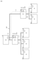
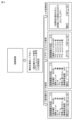
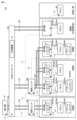
- FIG. 1 is a diagram illustrating an example of the configuration of an air conditioning system.
- FIG. 2 is a diagram for explaining a basic pattern for configuring an air conditioning system.
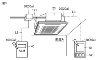
- 4 is a diagram for explaining the positional relationship between the indoor unit, the shutoff unit, the alarm unit, and the remote controller.
- FIG. FIG. 2 is a diagram showing an outline of the configuration of a cutoff unit. 2 is a block diagram showing the configurations of an outdoor unit, an indoor unit, a shutoff unit, and an alarm unit.
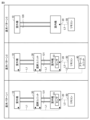
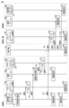
- FIG. 4 is a sequence diagram showing a process flow when a refrigerant leak is detected by a refrigerant sensor provided in an indoor unit.
- FIG. 4 is a sequence diagram showing a process flow when a refrigerant leak is detected by a refrigerant sensor provided in the alarm unit.
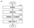
- 5 is a flowchart for explaining a process in which the shutoff unit closes the shutoff valve in the event of a power outage.
- 10 is a flowchart for explaining a process in which the indoor unit disables and enables a function of the refrigerant sensor in response to an operation of the sensor setting switch.
- FIG. 11 is a diagram showing another configuration example of an air conditioning system.
- FIG. 11 is a diagram showing communication paths of the air conditioning system shown in FIG. 10.
- 4 is a flowchart for explaining the flow of processing executed by the air conditioning system when the air conditioning system is started up.
- FIG. 11 is a flowchart illustrating an example of a grouping determination process.
- 10 is a flowchart illustrating a process flow relating to displaying a device configuration and releasing an interlock.
- FIG. 4 is a diagram for explaining information displayed on a screen of a remote controller.
- FIG. 4 is a diagram for explaining information displayed on a screen of a remote controller.
- FIG. 1 is a diagram showing an example of the configuration of an air conditioning system for a large space setting.
- FIG. 13 is a diagram showing an example of the configuration of an air conditioning system according to a modified example.
- FIG. 1 is a diagram showing an example of the configuration of an air conditioning system 100 according to an embodiment.
- the air conditioning system 100 shown in FIG. 1 includes an outdoor unit 10, an indoor unit 20, a shutoff unit 30, an alarm unit 40, and remote controllers 50 and 60.
- an example is described in which the air conditioning system 100 is applied to rooms A and B, which are examples of spaces to be air-conditioned, and a manager's room.
- the air conditioning system 100 shown in FIG. 1 includes multiple indoor units 20, shutoff units 30, alarm units 40, and remote controllers 50.
- the indoor units 20, shutoff units 30, alarm units 40, and remote controllers 50 may be referred to as indoor units 20a, 20b..., shutoff units 30a, 30b..., alarm units 40a, 40b..., and remote controllers 50a, 50b..., respectively.
- Each of rooms A and B is provided with an indoor unit 20, an alarm unit 40, and a remote controller 50.
- the indoor unit 20 is equipped with a refrigerant sensor 23 that detects refrigerant leaks.
- the alarm unit 40 has the function of detecting refrigerant leaks and the function of sounding an alarm of refrigerant leaks.
- the alarm unit 40 is placed in a location where it is thought that refrigerant leaking from the indoor unit 20 is easy to detect.
- the alarm unit 40 may be placed, for example, on the floor, wall, ceiling, etc. Multiple alarm units 40 may be placed in one room.
- the remote controller 50 is attached, for example, to a wall of a room.
- the remote controller 50 has a function of transmitting setting information such as the air conditioning temperature to the indoor unit 20, as well as a function of sounding an alarm in case of a refrigerant leak.
- the remote controller 50 is an example of an alarm device.
- a remote controller 60 is placed in the manager's room.
- a manager who manages the air-conditioned space is always present in the manager's room.
- the manager's room may be a night guard room, for example.
- the remote controller 60 is an example of a management alarm device. If a refrigerant leak occurs in either room A or B, the remote controller 60 issues an alarm for a refrigerant leak. The manager takes appropriate measures in response to the alarm issued by the remote controller 50.
- the outdoor unit 10, indoor unit 20, and shutoff unit 30 are connected by piping 120 through which the refrigerant flows.
- the piping 120 includes a pair of piping 121 that connects the indoor unit 20a and the shutoff unit 30a, and a pair of piping 122 that connects the indoor unit 20b and the shutoff unit 30b.
- the refrigerant circulates between the outdoor unit 10 and the indoor unit 20a via piping 120 that passes through the shutoff unit 30a.
- the refrigerant circulates between the outdoor unit 10 and the indoor unit 20b via piping 120 that passes through the shutoff unit 30b.
- the outdoor unit 10, the indoor unit 20a, the shutoff unit 30a, and the piping 120 form a refrigerant circulation flow path through which the refrigerant circulates.
- the outdoor unit 10, the indoor unit 20b, the shutoff unit 30b, and the piping 120 form a refrigerant circulation flow path through which the refrigerant circulates.
- the outdoor unit 10 is an example of a heat source unit.
- the indoor units 20a, 20b air-condition rooms A, B, respectively, by exchanging heat with the outdoor unit 10 via the refrigerant circulating through the refrigerant circulation path. If a refrigerant leak occurs in room A, the shutoff unit 30a has the function of shutting off the flow of refrigerant to the indoor unit 20a by closing the pipe 121. Similarly, if a refrigerant leak occurs in room B, the shutoff unit 30b has the function of shutting off the flow of refrigerant to the indoor unit 20b by closing the pipe 122.
- indoor unit 20a is the indoor unit subordinate to shutoff unit 30a
- indoor unit 20b is the indoor unit subordinate to shutoff unit 30b.
- the communication path L1 is an example of a communication path for establishing communication between the outdoor unit 10, the indoor unit 20a, the indoor unit 20b, the shutoff unit 30a, and the shutoff unit 30b.
- the shutoff unit 30a and the alarm unit 40a communicate through communication path L2.
- the shutoff unit 30b and the alarm unit 40b communicate through communication path L2.
- Communication path L2 is an example of a communication path for establishing communication between the shutoff unit 30 and the alarm unit 40.
- the indoor unit 20a and the remote controller 50a communicate through communication path L3.
- the indoor unit 20b and the remote controller 50b communicate through communication path L3.
- Communication path L3 is an example of a communication path for establishing communication between the indoor unit 20 and the remote controller 50.
- the indoor unit 20b and the remote controller 60 located in the manager's room communicate through communication path L3.
- the indoor unit 20a and the alarm unit 40a notify the shutoff unit 30a of the refrigerant leak.
- the shutoff unit 30a closes the pipe 121 based on the notification of the refrigerant leak.
- the indoor unit 20b and the alarm unit 40b notify the shutoff unit 30b of the refrigerant leak.
- the shutoff unit 30b closes the pipe 122 based on the notification of the refrigerant leak.
- the alarm unit 40a and remote controller 50a issue an alarm.
- the alarm unit 40b and remote controller 50b issue an alarm.
- the remote controller 60 located in the manager's room issues an alarm when a refrigerant leak is detected in the indoor unit 20a or alarm unit 40a, and when a refrigerant leak is detected in the indoor unit 20b or alarm unit 40b.
- a configuration for detecting a refrigerant leak and a configuration for reporting a refrigerant leak are redundantly arranged in each of rooms A and B. Therefore, with the air conditioning system 100, safety measures against refrigerant leaks can be strengthened compared to systems that do not employ such a redundant configuration.
- the communication paths for notifying the shutoff unit 30 of a refrigerant leak are different between the indoor unit 20 and the alarm unit 40 (communication paths L1, L2). Therefore, even if a communication failure occurs in one of the two communication paths (L1, L2), the refrigerant leak can be reliably notified to the shutoff unit 30 via the other communication path.
- the communication path L2 for reporting a refrigerant leak via the alarm unit 40 is different from the communication path L3 for reporting a refrigerant leak via the remote controllers 50 and 60. Therefore, even if a communication failure occurs on one of the two communication paths (L2, L3), a refrigerant leak alarm can be reliably issued on the other communication path.
- the shutoff units 30a and 30b separate the areas where the flow of refrigerant is stopped. Therefore, for example, even if the operation of the indoor unit 20a in room A is stopped due to the detection of a refrigerant leak in room A, the operation of the indoor unit 20b in room B can continue.
- the configuration shown in FIG. 1 includes an equipment configuration for preparing for refrigerant leakage.
- the equipment configuration for preparing for refrigerant leakage may be referred to as a "safety device.”
- the air conditioning system 100 can be constructed in a variety of configurations, as will be introduced later.
- the air conditioning system 100 may be constructed in one of a number of basic patterns, or may be constructed by combining two or more basic patterns.
- these basic patterns there are patterns that include safety devices and patterns that do not include safety devices. Next, an example of one of these basic patterns will be described.
- FIG. 2 is a diagram for explaining the basic patterns that make up the air conditioning system 100.
- Basic patterns 1 to 3 are shown in FIG. 2.
- Basic pattern 1 includes an outdoor unit 10, an indoor unit 20, a shutoff unit 30, and a remote controller 50.
- Basic pattern 1 does not include an alarm unit 40.
- the shutoff unit 30, the refrigerant sensor 23, and the remote controller 50 function as safety devices.
- Basic pattern 2 includes an alarm unit 40 in addition to the equipment configuration of basic pattern 1.
- the shutoff unit 30, refrigerant sensor 23, remote controller 50, and alarm unit 40 function as safety devices.
- the refrigerant sensor 23 may be designed not to function. This is because a refrigerant leak would be detected by the alarm unit 40. In this case, the sensor function of the refrigerant sensor 23 may be set to off, or the refrigerant sensor 23 itself may be removed from the indoor unit 20.
- Basic pattern 3 includes the outdoor unit 10, the indoor unit 20, and the remote controller 50.
- Basic pattern 3 does not include the shutoff unit 30 and the alarm unit 40.
- the refrigerant sensor 23 is not connected to the indoor unit 20. Therefore, basic pattern 3 does not have a safety device.
- Basic pattern 3 may be applied to rooms with a large indoor space. In a room with a large indoor space, even if a refrigerant leak occurs in the indoor unit 20, the leaked refrigerant will diffuse throughout the large space of the room, so it is unlikely that the refrigerant leak will immediately have a negative impact on the air-conditioned environment.
- the designer designs the air conditioning system 100 by combining basic patterns 1 to 3 in various ways.
- the contractor constructs the system based on the design, and before conducting a test run of the system, verifies that the constructed system is configured as designed.
- FIG. 3 is a diagram for explaining the relative positions of the indoor unit 20, the shutoff unit 30, the alarm unit 40, and the remote controller 50.
- the relative positions of the indoor unit 20 (20a) and the like are explained using room A shown in FIG. 1 as a representative example.
- the indoor unit 20a is embedded in the ceiling of room A, which is the space to be air-conditioned.
- the shutoff unit 30a is placed in the attic of room A.
- the alarm unit 40a is placed on the floor of room A, etc.
- the alarm unit 40a is equipped with an LED (Light Emitting Diode) 45 for displaying an alarm.
- the alarm unit 40a is communicatively connected to the shutoff unit 30a via a communication path L2. Power is supplied from the shutoff unit 30a to the alarm unit 40a.
- the alarm unit 40 and the shutoff unit 30 may be configured to be wirelessly connected.
- the shutoff unit 30 is an example of a shutoff device
- the alarm unit 40 is an example of an alarm sensor device
- the remote controllers 50 and 60 are examples of alarm devices.
- the remote controller 50a is placed on the wall of room A for the convenience of the user.
- the remote controller 50a is communicatively connected to the cutoff unit 30a via a communication path L3.
- the remote controller 50a includes a display 51 and an operation unit 52.
- the user operates the operation unit 52 to input setting information, including the room temperature setting, into the remote controller 50a.
- the display 51 shows the room temperature and various other information.
- the shutoff unit 30a and the indoor unit 20a are connected by a pair of pipes 121 through which the refrigerant flows.
- the refrigerant sensor 23 is disposed near the pipes 121 that pass through the indoor unit 20a.
- the remote controller 50a issues an alarm sound based on the notification of the refrigerant leak and displays alarm information on the display 51.
- the remote controller 50a may be equipped with an LED for displaying the alarm. When displaying alarm information on the display 51, the remote controller 50a may turn on the backlight of the display 51.
- room A the layout of the indoor unit 20 (20a) and other components has been described using room A as a representative example.
- the indoor unit 20b, shutoff unit 30b, alarm unit 40b, and remote controller 50b are arranged in the same manner as in room A.
- FIG. 4 is a diagram showing an outline of the configuration of the shutoff unit 30.
- the shutoff unit 30a includes a shutoff valve 34 that shuts off a pair of pipes 121, and a substrate 300 that opens and closes the shutoff valve 34.
- the pair of pipes 121 includes pipe 121a through which refrigerant flows from the outdoor unit 10 to the indoor unit 20a, and pipe 121b through which refrigerant flows from the indoor unit 20a to the outdoor unit 10. Liquid refrigerant flows through one of the pipes 121a, 121b, and gas refrigerant flows through the other.
- Shut-off valve 34 includes shut-off valve 34a attached to pipe 121a and shut-off valve 34b attached to pipe 121b.
- Shut-off valve 34 is, for example, a linear expansion valve.
- the board 300 communicates with the outdoor unit 10 and the indoor unit 20a through communication path L1, and with the alarm unit 40a through communication path L2.
- the board 300 is provided with multiple terminals 370 for connecting multiple alarm units 40.
- the board 300 closes the shutoff valves 34a, 34b when a refrigerant leak is notified from the indoor unit 20a and when a refrigerant leak is notified from the alarm unit 40a. This closes the pipes 121a, 121b.
- multiple indoor units 20 may be connected in parallel to the pipe 121.
- FIG. 5 is a block diagram showing the configurations of the outdoor unit 10, indoor unit 20, shutoff unit 30, and alarm unit 40.
- FIG. 5 shows the outdoor unit 10, indoor units 20a, 20b, shutoff units 30a, 30b, and alarm units 40a, 40b.
- the indoor units 20a, 20b have a common configuration
- the shutoff units 30a, 30b have a common configuration
- the alarm units 40a, 40b have a common configuration.
- FIG. 5 shows the detailed configurations of the indoor unit 20a, shutoff unit 30a, and alarm unit 40a, while omitting the detailed configurations of the indoor unit 20b, shutoff unit 30b, and alarm unit 40b.
- the outdoor unit 10 includes an air conditioning mechanism 14.
- the air conditioning mechanism 14 includes a compressor 141, a heat exchanger 142, a fan 144, and a four-way valve 145.
- a control device 15 is disposed in the outdoor unit 10.
- the control device 15 controls the air conditioning mechanism 14 and communicates with devices in the air conditioning system 100, including the indoor unit 20 and the shutoff unit 30.
- the control device 15 includes a processor 11, a memory 12, and a communication circuit 13.
- the processor 11 is typically configured with a CPU (Central Processing Unit) or an MPU (Multi-Processing Unit).
- the control device 15 is also an example of a processing circuit.
- the processor 11 is an example of an arithmetic device.
- the processor 11 controls various devices according to a program. This control is not limited to processing by software, but can also be processed by dedicated hardware (electronic circuitry).
- the memory 12 includes an area in which the programs executed by the processor 11 are stored, an area in which the processor 11 temporarily stores program code and work memory, and an area in which an ID for other devices such as the cutoff unit 30 to identify the outdoor unit 10 is stored.
- the memory 12 includes volatile memory such as DRAM (dynamic random access memory) and SRAM (static random access memory), ROM (read only memory), and non-volatile memory such as flash memory.
- the memory 12 may be an SSD (solid state drive) or HDD (hard disk drive), etc.
- the memory 12 stores an ID (address) for devices communicating with the outdoor unit 10 to identify the outdoor unit 10.
- Processor 11 has a communication function. Processor 11 allows the communication destination to identify the source of communication by transmitting data including an ID to the communication destination. Processor 11 communicates with cutoff units 30 (30a, 30b) via communication circuit 13. Processor 11 also communicates with indoor units 20 (20a, 20b) via communication circuit 13 and cutoff unit 30. Processor 11 also communicates with a remote controller 60 located in the manager's room via communication circuit 13, cutoff unit 30a, cutoff unit 30b, and indoor unit 20b.
- the indoor unit 20 (20a, 20b) includes a processor 21, a memory 22, a refrigerant sensor 23, a sensor terminal 23a, an air conditioning mechanism 24, a sensor setting switch 25, a communication circuit 26, and a communication interface (I/F) 27.
- the air conditioning mechanism 24 includes a heat exchanger 242, an expansion valve 243, and a fan 244.
- the heat exchanger 242 is an example of a heat exchanger that exchanges heat with the heat source unit.
- the air conditioning mechanism 14 of the outdoor unit 10, the air conditioning mechanism 24 of the indoor unit 20, and the piping 120 form a refrigerant circulation path and a refrigerant circuit through which the refrigerant circulates.
- the memory 22 includes an area in which an ID (address) for identifying the indoor unit 20 by the outdoor unit 10 and the shutoff unit 30 is stored.
- ID address
- the detailed configuration of the processor 21 and the memory 22 is similar to that of the processor 11 and the memory 12 already described, and therefore the description will not be repeated here.
- the refrigerant sensor 23 is connected to the sensor terminal 23a.
- the refrigerant sensor 23 detects refrigerant leaks in the indoor unit 20.
- the sensor setting switch 25 is a switch for switching the sensor function of the refrigerant sensor 23 between on and off.
- the sensor setting switch 25 is operated, for example, by a worker performing maintenance on the indoor unit 20. Note that the worker may disable the refrigerant sensor 23 by removing the refrigerant sensor 23 from the sensor terminal 23a.
- the processor 21 acquires sensor information from the refrigerant sensor 23.
- the processor 21 has a communication function.
- the processor 21 allows the communication destination to identify the source of communication by transmitting data including the ID stored in the memory 22 to the communication destination.
- the processor 21 communicates with the blocking unit 30 through the communication circuit 26.
- the processor 21 communicates with the remote controller 50 through the communication interface 27.
- the shutoff unit 30 (30a, 30b) includes a processor 31, a memory 32, a shutoff valve 34 (34a, 34b), a standby power supply 35, a communication circuit 33, a b-contact relay 36, and a communication interface (I/F) 37.
- the communication interface 37 includes a number of terminals 370 as shown in FIG. 3.
- the b-contact relay 36 is disposed in the communication path L1 that connects the communication circuit 13 of the outdoor unit 10 and the communication circuit 26 of the indoor unit 20.
- the b-contact relay 36 is composed of, for example, a drive coil and a contact.
- the communication circuit 33 of the cutoff unit 30 controls the state of the b-contact relay 36 to an open state or a closed state based on a command from the outdoor unit 10.
- the b-contact relay 36 functions as a switch that turns off when current is flowing through the drive coil to cut off the communication path L1, and turns on when current is not flowing through the drive coil to make the communication path L1 conductive. Therefore, when the power supply to the cutoff unit 30 is stopped, the conductive state of the communication path L1 is maintained. Therefore, compared to the case where an a-contact relay is used as the relay, it is possible to prevent the communication circuit from being cut off during a power outage. Note that instead of the b-contact relay 36, the communication path L1 may be switched between an open state and a closed state by other switching elements such as a transistor and a filter.
- Memory 32 includes an area in which an ID is stored that allows other devices, such as outdoor unit 10, to identify shutoff unit 30.
- the detailed configurations of processor 31 and memory 32 are similar to those of processor 11 and memory 12 already described, and therefore will not be described again here.
- the processor 31 has a communication function.
- the processor 31 transmits data including the ID stored in the memory 32 to the communication destination, thereby allowing the communication destination to identify the communication source.
- the processor 31 communicates with the outdoor unit 10 via the communication circuit 33.
- the processor 31 communicates with the indoor unit 20 via the communication circuit 33.
- the processor 31 communicates with the alarm unit 40 via the communication interface 37.
- the processor 31 closes the shutoff valves 34a and 34b. This closes the pipes 121a and 121b.
- the shutoff unit 30 switches the power supply source from the main power source to the backup power source 35.
- the backup power source 35 is composed of, for example, a secondary battery.
- the processor 31 operates using power supplied from the backup power source 35 and closes the shutoff valves 34a and 34b. This stops the supply of refrigerant to the indoor unit 20 during the power outage.
- the alarm unit 40 includes a processor 41, a memory 42, a refrigerant sensor 43, a speaker 44, an LED 45, and a communication interface (I/F) 47.
- the memory 42 includes an area in which an ID is stored that allows other devices, such as the cutoff unit 30, to identify the alarm unit 40.
- the detailed configurations of the processor 41 and memory 42 are similar to those of the processor 11 and memory 12 already described, and therefore will not be described again here.
- the refrigerant sensor 43 detects refrigerant leaks.
- the refrigerant sensor 43 is an example of an indoor refrigerant sensor.
- the processor 41 acquires sensor information from the refrigerant sensor 43. If a refrigerant leak is detected, the processor 41 generates an alarm sound from the speaker 44 and turns on the LED 45.
- the processor 41 has a communication function.
- the processor 41 allows the communication destination to identify the source of the communication by transmitting data including the ID stored in the memory 42 to the communication destination.
- the processor 41 communicates with the blocking unit 30 through the communication interface 47.
- FIG. 6 is a sequence diagram showing the process flow when a refrigerant leak is detected by the refrigerant sensor 23 of the indoor unit 20a.
- the alarm unit 40b and remote controller 50b located in room B are omitted from the illustration. The process flow will be explained below with reference to FIG. 6.
- the refrigerant sensor 23 detects a refrigerant leak in the indoor unit 20a (step S1).
- the indoor unit 20a notifies the remote controller 50a of the refrigerant leak (step S2), notifies the shutoff unit 30a of the refrigerant leak (step S4), and notifies the outdoor unit 10 of the refrigerant leak (step S8).
- the indoor unit 20a saves the history of the refrigerant leak in the memory 22 (see FIG. 5) (step S13) and stops air conditioning operation (step S14).
- the order in which steps S2, S4, S8, S13, and S14 are performed may be changed.
- the remote controller 50a issues an alarm based on the notification from the indoor unit 20a (step S3). More specifically, the remote controller 50a issues an alarm sound based on the notification of the refrigerant leak and displays alarm information. This allows the user in room A to become aware of the refrigerant leak. The remote controller 50a then saves the history of the refrigerant leak (step S18).
- the shutoff unit 30a closes the shutoff valves 34a and 34b based on the notification from the indoor unit 20a (step S5).
- the shutoff unit 30a closes the shutoff valves 34a and 34b, the pipes 121a and 121b are closed. This prevents the refrigerant leak from spreading.
- the shutoff unit 30a further notifies the alarm unit 40a of the refrigerant leak (step S6).
- the shutoff unit 30a then saves the refrigerant leak history in the memory 32 (see FIG. 5) (step S15).
- steps S5, S6, and S15 may be changed.
- the shutoff unit 30a may notify the outdoor unit 10 of the refrigerant leak (step S8a).
- the alarm unit 40a issues an alarm based on the notification from the shutoff unit 30a (step S7). More specifically, the alarm unit 40a issues an alarm sound and turns on the LED 45 (see FIG. 5) based on the notification of the refrigerant leak. This allows the user in room A to become aware of the refrigerant leak.
- the outdoor unit 10 notifies the remote controller 60 located in the manager's room of the refrigerant leak based on the notification from the indoor unit 20a (step S9).
- the outdoor unit 10 further notifies the shutoff unit 30b and the indoor unit 20b located in room B of the refrigerant leak in room A based on the notification from the indoor unit 20a. More specifically, the outdoor unit 10 notifies the shutoff unit 30b and the indoor unit 20b of a "maintenance abnormality" message (steps S11 and S12).
- the order in which steps S9, S11, and S12 are performed may be changed.
- the outdoor unit 10 then saves the refrigerant leak history in the memory 12 (see FIG. 4) (step S19).
- the remote controller 60 issues an alarm based on the notification from the outdoor unit 10 (step S10). More specifically, the remote controller 60 issues an alarm sound based on the notification of a refrigerant leak and displays alarm information. This allows the manager to become aware of the refrigerant leak. The remote controller 60 then saves the history of the refrigerant leak (step S20).
- the shutoff unit 30b arranged in room B stores the refrigerant leak history information in memory 32 (see FIG. 5) based on the notification from the outdoor unit 10 (step S16).
- the indoor unit 20b arranged in room B stores the refrigerant leak history information in memory 22 (see FIG. 5) based on the notification from the outdoor unit 10 (step S17).
- the outdoor unit 10 It is desirable for the outdoor unit 10 to transmit the ID of the indoor unit 20a in which a refrigerant leak has been detected in each of steps S9, S11, and S12.
- the remote controller 60 may issue an alarm including the ID of the indoor unit 20 in which a refrigerant leak is occurring.
- each of the shutoff unit 30b and the indoor unit 20b may save a history including the ID of the indoor unit 20 in which a refrigerant leak is occurring.
- FIG. 7 is a sequence diagram showing the process flow when a refrigerant leak is detected by the refrigerant sensor 43 of the alarm unit 40a.
- the alarm unit 40b and remote controller 50b placed in room B are omitted. The process flow will be explained below with reference to FIG. 7.
- the refrigerant sensor 43 detects a refrigerant leak in room A (step S31).
- the alarm unit 40a issues an alarm (step S32). More specifically, the alarm unit 40a issues an alarm sound and turns on the LED 45 (see FIG. 5) based on the notification of the refrigerant leak. This allows the user in room A to become aware of the refrigerant leak.
- the alarm unit 40a further notifies the shutoff unit 30a of the refrigerant leak (step S33). The order in which steps S31 and S32 are executed may be changed.
- the shutoff unit 30a closes the shutoff valves 34a and 34b based on the notification from the alarm unit 40a (step S34).
- the shutoff unit 30a closes the shutoff valves 34a and 34b, the pipes 121a and 121b are closed. This prevents the refrigerant leak from spreading.
- the shutoff unit 30a further notifies the indoor unit 20a and the outdoor unit 10 of the refrigerant leak (steps S35 and S38).
- the shutoff unit 30a then stores the history of the refrigerant leak in the memory 32 (see FIG. 5) (step S45). The order in which steps S33, S34, S38, and S45 are performed may be changed.
- the indoor unit 20a notifies the remote controller 50a of the refrigerant leak based on the notification from the shutoff unit 30a (step S36). After that, the indoor unit 20a saves the refrigerant leak history in the memory 22 (see FIG. 5) (step S43) and stops the air conditioning operation (step S44). The order in which steps S36, S43, and S44 are executed may be changed.
- the remote controller 50a issues an alarm based on the notification from the indoor unit 20a (step S37). More specifically, the remote controller 50a issues an alarm sound based on the notification of the refrigerant leak and displays alarm information. This allows the user in room A to become aware of the refrigerant leak. The remote controller 50a then saves the history of the refrigerant leak (step S48).
- the outdoor unit 10 notifies the remote controller 60 located in the manager's room of the refrigerant leak based on the notification from the shutoff unit 30a (step S39).
- the outdoor unit 10 further notifies the shutoff unit 30b and the indoor unit 20b located in room B of the refrigerant leak in room A based on the notification from the shutoff unit 30a. More specifically, the outdoor unit 10 notifies the shutoff unit 30b and the indoor unit 20b of the refrigerant leak (steps S41 and S42) with a message that reads "Maintenance abnormality."
- the order in which steps S39, S41, and S42 are performed may be changed.
- the outdoor unit 10 then saves the history of the refrigerant leak in memory 12 (see FIG. 4) (step S49).
- the remote controller 60 issues an alarm based on the notification from the outdoor unit 10 (step S40). More specifically, the remote controller 60 issues an alarm sound based on the notification of a refrigerant leak and displays alarm information. This allows the manager to become aware of the refrigerant leak. The remote controller 60 then saves the history of the refrigerant leak (step S50).
- the shutoff unit 30b arranged in room B stores the refrigerant leak history information in memory 32 (see FIG. 5) based on the notification from the outdoor unit 10 (step S46).
- the indoor unit 20b arranged in room B stores the refrigerant leak history information in memory 22 (see FIG. 5) based on the notification from the outdoor unit 10 (step S47).
- FIG. 8 is a flowchart for explaining the process in which the shutoff unit 30 closes the shutoff valves 34 (34a, 34b) in the event of a power outage. The process executed by the shutoff unit 30 will be explained below based on the flowchart.
- step S101 When a power outage occurs (step S101), the shutoff unit 30 detects the power outage (step S102). Next, the shutoff unit 30 starts supplying power from the backup power supply 35 before the power supplied from the main power supply falls below a threshold (step S103). Next, the shutoff unit 30 closes the shutoff valve 34 using the power supplied from the backup power supply 35 (step S104).
- the shutoff unit 30 starts supplying power from the backup power source 35 and closes the shutoff valve 34 before the power supplied from the main power source falls below the threshold (step S104). Therefore, the air conditioning system 100 can prevent refrigerant leakage in the event of a power outage.
- FIG. 9 is a flowchart for explaining the process in which the indoor unit 20 disables and enables the function of the refrigerant sensor 23 in response to the operation of the sensor setting switch 25. The process executed by the indoor unit 20 will be explained below based on the flowchart.
- the indoor unit 20 determines whether or not an operation to turn off the sensor function of the refrigerant sensor 23 has been detected (step S201). If the indoor unit 20 detects an operation to turn off the sensor function of the refrigerant sensor 23, it disables the sensor function of the refrigerant sensor 23 (step S202).
- the indoor unit 20 determines whether or not it has detected an operation to turn on the sensor function of the refrigerant sensor 23 (step S203). If the indoor unit 20 detects an operation to turn on the sensor function of the refrigerant sensor 23, it enables the sensor function of the refrigerant sensor 23 (step S204). If the indoor unit 20 does not detect an operation to turn on the sensor function of the refrigerant sensor 23, it ends the processing based on this flowchart.
- the refrigerant sensor 23 of the indoor unit 20 is enabled or disabled. If sufficient safety measures against refrigerant leakage have been implemented according to the air conditioning environment of the room, the designer may turn off the function of the refrigerant sensor 23 of the indoor unit 20. For example, the function of the refrigerant sensor 23 may be turned off in each of the cases where multiple alarm units 40 are placed in the room and where a ventilation device with high ventilation capacity is placed in the room.
- the blocking unit 30 is disposed as a separate device from the indoor unit 20.
- the blocking unit 30 may also be built into the indoor unit 20.
- the blocking unit 30a may be built into the indoor unit 20a
- the blocking unit 30b may be built into the indoor unit 20b.
- This modification discloses a configuration in which the blocking unit 30 is built into the indoor unit 20 in the air conditioning system 100 that includes the indoor unit 20 and the blocking unit 30.
- Figure 10 is a diagram showing another example of the configuration of the air conditioning system 100.
- Figure 10 shows an example in which multiple indoor units 20 are connected in parallel under each of the shutoff units 30a and 30b.
- Indoor units 20a, 20c, and 20d are provided under the shutoff unit 30a.
- Indoor units 20b and 20e are provided under the shutoff unit 30b.
- Indoor units 20a, 20c, and 20d are connected in parallel to pipe 121, which is connected to shutoff unit 30a. Therefore, refrigerant flows between outdoor unit 10 and indoor unit 20a through pipe 121, refrigerant flows between outdoor unit 10 and indoor unit 20c through pipe 121, and refrigerant flows between outdoor unit 10 and indoor unit 20d through pipe 121.
- Indoor units 20b and 20e are connected in parallel to pipe 122, which is connected to shutoff unit 30b. Therefore, refrigerant flows between outdoor unit 10 and indoor unit 20b through pipe 122, and refrigerant flows between outdoor unit 10 and indoor unit 20e through pipe 122.
- Indoor units 20a and 20c are located in room A.
- Indoor unit 20b is located in room B.
- Indoor unit 20d is located in room C.
- Indoor unit 20e is located in room D.
- Remote controllers 50a and 50c are provided in room A corresponding to indoor units 20a and 20c, respectively.
- Remote controller 50b corresponding to indoor unit 20b is provided in room B.
- Remote controller 50d corresponding to indoor unit 20d is provided in room C.
- Remote controller 50e corresponding to indoor unit 20e is provided in room D.
- Rooms A to C use the configuration of basic pattern 2 shown in FIG. 2.
- Room D uses the configuration of basic pattern 1 shown in FIG. 2.
- Alarm units 40a and 40c are placed in room A.
- Alarm unit 40b is placed in room B.
- Alarm unit 40d is placed in room C.
- Indoor units 20a, 20c, 20d and alarm units 40a, 40c notify shutoff unit 30a of a refrigerant leak.
- Indoor units 20b, 20e and alarm unit 40b notify shutoff unit 30b of a refrigerant leak.
- shutoff unit 30a When shutoff unit 30a is notified of a refrigerant leak, it closes pipe 121 with shutoff valve 34 and stops air conditioning operation of indoor units 20a, 20c, 20d.
- shutoff unit 30b When shutoff unit 30b is notified of a refrigerant leak, it closes pipe 122 with shutoff valve 34 and stops air conditioning operation of indoor units 20b, 20e.
- Shutoff unit 30a communicates with alarm units 40a, 40c, and 40d via communication path L2.
- Shutoff unit 30b communicates with alarm unit 40b via communication path L2.
- the indoor unit 20a communicates with the remote controller 50a through communication path L3.
- the indoor unit 20b communicates with the remote controller 50b through communication path L3.
- the indoor unit 20c communicates with the remote controller 50c through communication path L3.
- the indoor unit 20d communicates with the remote controller 50d through communication path L3.
- the indoor unit 20e communicates with the remote controller 50e through communication path L3.
- the outdoor unit 10 and the shutoff units 30a and 30b communicate via communication path L1.
- the outdoor unit 10 and the indoor units 20a to 20e communicate via communication path L1.
- the shutoff unit 30a and the indoor units 20a, 20c, and 20d communicate via communication path L1.
- the shutoff unit 30b and the indoor units 20b and 20e communicate via communication path L1.
- FIG. 11 is a diagram showing the communication path L1 of the air conditioning system 100 shown in FIG. 10.
- OC means “outdoor unit”
- IC means “indoor unit”
- SV means “shutoff unit”.
- communication path L1 connects the communication circuit 13 of the outdoor unit 10, the communication circuits 33 of the shutoff units 30a and 30b, and the communication circuits 26 of the indoor units 20a to 20e.
- the communication circuit 13 of the outdoor unit 10 and the communication circuit 33 of the shutoff unit 30a are connected by wiring.
- the communication circuit 13 of the outdoor unit 10 and the communication circuit 33 of the shutoff unit 30b are connected by wiring.
- the communication circuit 13 of the outdoor unit 10 and the communication circuit 26 of the indoor unit 20a are connected by wiring via the communication circuit 33 of the shutoff unit 30a and the b-contact relay 36 of the shutoff unit 30a.
- the communication circuit 13 of the outdoor unit 10 and the communication circuit 26 of the indoor unit 20b are connected by wiring via the communication circuit 33 of the shutoff unit 30b and the b-contact relay 36 of the shutoff unit 30b.
- the communication circuit 26 of the indoor unit 20a, the communication circuit 26 of the indoor unit 20c, and the communication circuit 26 of the indoor unit 20d are connected in series by wiring.
- the communication circuit 26 of the indoor unit 20b and the communication circuit 26 of the indoor unit 20e are connected by wiring.
- the communication circuit 33 of the cutoff unit 30a turns the b-contact relay 36 of the cutoff unit 30a on/off in response to a command from the outdoor unit 10.
- the b-contact relay 36 of the cutoff unit 30a changes from on to off, communication between the indoor units 20a, 20c, and 20d and the outdoor unit 10 is cut off.
- the communication circuit 33 of the cutoff unit 30b turns the b-contact relay 36 of the cutoff unit 30b on/off in response to a command from the outdoor unit 10.
- the b-contact relay 36 of the cutoff unit 30b changes from on to off, communication between the indoor units 20b, 20e and the outdoor unit 10 is cut off.
- the outdoor unit 10 identifies the indoor unit 20 that is provided under each breaker unit 30 by controlling the state of the b-contact relay 36 provided in each breaker unit 30. The method of identification will be described in detail below.
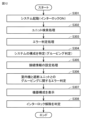
- FIG. 12 is a flowchart for explaining the flow of processing executed by the air conditioning system 100 when the air conditioning system 100 is started.
- the air conditioning system 100 After receiving a start command from the contractor, the air conditioning system 100 according to this embodiment sets the interlock to ON. This causes the air conditioning system 100 to enter a state in which air conditioning operation is prohibited.
- the contractor confirms that the configuration of the air conditioning system 100 is as designed, the contractor inputs a command to release the interlock to the air conditioning system 100.
- the air conditioning system 100 starts air conditioning operation based on the command to release the interlock.
- the contractor is an example of a user.
- step S301 when the control device 15 receives a startup command from the contractor, it starts the air conditioning system 100 (step S301).
- an interlock for prohibiting air conditioning operation of the air conditioning system 100 is set to ON.
- the interlock may be, for example, a data flag that prohibits air conditioning operation by the system.
- the control device 15 does not perform air conditioning operation.
- the contractor's instructions are input to the control device 15 of the outdoor unit 10 via, for example, a remote controller 50.
- a remote controller 50 a maintenance controller owned by the contractor may be used.
- step S302 the control device 15 requests a response from devices connected to the system, targeting a certain range of IDs (addresses).
- the ID range is, for example, 0 to 255.
- an ID is stored in each device, including the indoor unit 20, the shutoff unit 30, and the alarm unit 40.
- each device receives a response including its own ID, it transmits a response including attribute information and capability information to the control device 15.
- the attribute information is information that indicates the attributes of devices such as the shutoff unit and indoor unit.
- the capability information is information that indicates the capabilities of the devices.
- the control device 15 executes a unit search process to identify the IDs of the indoor units 20 and shutoff units 30 connected to the system.
- control device 15 executes an error determination process based on the information collected in the unit search process (step S303). More specifically, the control device 15 checks whether the number of connected devices and the capacity of the connected indoor units exceed the allowable capacity.
- Step S304 includes a grouping determination process.
- the control device 15 identifies the relationship between the shutoff units 30 and the indoor units 20 subordinate to them. In other words, the control device 15 identifies the "connection relationship between the shutoff units 30 and the indoor units 20.”
- the control device 15 turns on/off the b-contact relay 36 provided in each cutoff unit 30 to identify the "connection relationship between the cutoff unit 30 and the indoor unit 20." This control will be explained later using FIG. 13. Note that the control device 15 skips this process if the system does not include a cutoff unit 30.
- step S304 the control device 15 acquires information about the shutoff units 30 from each shutoff unit 30, and acquires information about the indoor units 20 from each indoor unit 20.
- the information about the shutoff unit 30 includes information about the alarm unit 40 connected to the shutoff unit 30.
- the information about the alarm unit 40 connected to the shutoff unit 30 includes information about the number of alarm units 40 and whether the alarm of the alarm unit 40 is enabled or disabled.
- the information about the indoor unit 20 includes information about whether the refrigerant sensor 23 is connected, information about whether the function of the refrigerant sensor 23 is enabled or disabled, and information about whether the alarm function of the remote controller 50 is enabled or disabled.
- step S304 the control device 15 further determines the number and connection relationships of the shutoff units 30 and indoor units 20. If the system includes one or more ventilation devices, the control device 15 also determines the number of ventilation devices. Note that at this stage, the control device 15 has not acquired information regarding the alarm unit 40. The control device 15 transmits information regarding the determined connection relationships to each indoor unit 20 and each shutoff unit 30.
- Step S304 further includes processing by the indoor unit 20.
- the indoor unit 20 identifies the shutoff unit 30 that is in a connection relationship with the indoor unit 20 from among the multiple shutoff units 30 based on the information on the connection relationship received from the control device 15. For example, in the configuration example shown in FIG. 10, the indoor unit 20a identifies that it is in a connection relationship with the shutoff unit 30a. Also, the indoor unit 20b identifies that it is in a connection relationship with the shutoff unit 30b. Furthermore, the indoor unit 20 identifies the alarm unit 40 that is connected to communicate with the shutoff unit 30 that is in a connection relationship. For example, in the configuration example shown in FIG.
- the indoor unit 20a identifies the alarm units 40a and 40c that are connected to communicate with the shutoff unit 30a. Also, the indoor unit 20b identifies the alarm unit 40b that is connected to communicate with the shutoff unit 30b. In this way, in this embodiment, part of the information on the system configuration is acquired by the indoor unit 20.
- control device 15 executes a connection information setting process (step S305). More specifically, the control device 15 transmits information on the "connection relationship between the shutoff unit 30 and the indoor unit 20" to each shutoff unit 30 and each indoor unit 20 included in the system. At this time, the indoor unit 20 and the shutoff unit 30 check various setting information with the control device 15. For example, the shutoff unit 30 or the indoor unit 20 may determine whether the function of the sensor that detects refrigerant leakage is enabled/disabled by inquiring of the outdoor unit 10 about the model of the outdoor unit 10.
- the indoor unit 20 may disable the function of the refrigerant sensor 23.
- the indoor unit 20 receives information about the "connection relationship between the shutoff unit 30 and the indoor unit 20" from the control device 15, and also acquires information about the alarm unit 40 by itself, making it possible to display the system's equipment configuration on the remote control 50.
- control device 15 executes an error determination regarding the grouping of the indoor units 20 and the shutoff units 30 (step S306). More specifically, the control device 15 determines that an error has occurred if the "connection relationship between the shutoff units 30 and the indoor units 20" differs from the expected relationship.
- the control device 15 determines that an error has occurred. In this case, the control device 15 displays an error code on the remote controller 50 or the like, and urges the contractor to restart the system. The control device 15 may transmit the error code to the indoor unit 20 in which the error has occurred. In this case, the indoor unit 20 may display the error code on the corresponding remote controller 50. If no error has occurred, the control device 15 stores information regarding the connection relationship between the shutoff unit 30 and the indoor units 20 in the memory 12 of the control device 15.
- the indoor unit 20 displays the system's equipment configuration on the remote controller 50 based on the information about the alarm unit 40 acquired in step S304 and the information received from the control device 15 in step S305 (step S307).
- information about the equipment configuration is displayed on the remote controller 50a.
- the contractor compares the equipment configuration displayed on the remote controller 50 with the equipment configuration shown on the design drawings to confirm that the system's safety devices have been installed according to the design drawings.
- the control device 15 may check the number of alarm units 40 and the presence or absence of a shutoff valve 34 with the shutoff unit 30, and transmit the confirmation result to the indoor unit 20. Also, before step S307, the indoor unit 20 may check the connection state of the refrigerant sensor 23 and the connection state of the remote controller 50, and transmit the confirmation result to the control device 15. In step 307, the indoor unit 20 may also display the confirmation results of the control device 15 and the indoor unit 20 on the remote controller 50.
- control device 15 determines whether or not to release the interlock (step S308). More specifically, if the construction contractor approves the configuration displayed in step S307, the control device 15 releases the interlock and ends the processing based on this flowchart. This puts the air conditioning system 100 in a state in which air conditioning operation is permitted. The processing of steps S307 and 308 will be described in detail later using FIG. 14.
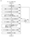
- FIG. 13 is a flow chart for explaining an example of the grouping judgment process. This process is included in step S304 in FIG. 12.
- the control device 15 sets an initial value to n (step S401).
- n is a variable for identifying each of the multiple interruption units 30 to be judged.
- the interruption unit 30 to be judged is changed as n is updated in step S406.
- control device 15 opens only the b-contact relay 36 of the shutoff unit n and closes the b-contact relays 36 of the other shutoff units (step S402).
- control device 15 sends a request to all indoor units 20 in the system (step S403).
- control device 15 identifies the indoor units 20 that do not respond to the sent request as indoor units subordinate to the shutoff unit n (step S404).
- the control device 15 can confirm responses from the indoor units 20b and 20e, but cannot confirm responses from the indoor units 20a, 20c, and 20d.
- the control device 15 determines that the indoor units 20a, 20c, and 20d exist under the shutoff unit 30a. In other words, the control device 15 determines that the indoor units 20a, 20c, and 20d are connected to the shutoff unit 30a.
- step S404 the control device 15 determines whether or not the processing of step S402 for all the cutoff units 30 has been completed (step S405). If the processing of step S402 for all the cutoff units 30 has not been completed, the control device 15 updates n (step S406). After that, the control device 15 returns the processing to step S402.
- control device 15 When the control device 15 has completed the process of step S402 for all the shutoff units 30, it opens the b-contact relays 36 of all the shutoff units 30 (step S407). Next, if there is an indoor unit 20 that has responded, the control device 15 identifies such an indoor unit 20 as an indoor unit 20 that is not connected to any shutoff unit 30 (basic pattern 3) (step S408). Next, the control device 15 closes the b-contact relays 36 of all the shutoff units 30 (step S409). After that, the control device 15 stores the identification results from the processes of steps S404 and S408 in the memory 12 (step S410), and ends the process based on this flowchart. At this time, information indicating the connection relationship between the shutoff unit 30 and the indoor unit 20 is stored for each shutoff unit 30 in the memory 12 of the control device 15.
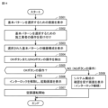
- FIG. 14 is a flowchart for explaining an example of the process for displaying the device configuration and releasing the interlock.
- FIGS. 15 and 16 are diagrams for explaining the information displayed on the screen of the remote controller. The process shown in FIG. 14 corresponds to the process of steps S307 and S308 in FIG. 12.
- the indoor unit 20 displays a screen for selecting a basic pattern on the display 51 of the remote controller 50 (step S501).
- Fig. 15 shows an example of a screen for selecting a basic pattern.
- the remote controller 50 displays a screen for selecting a basic pattern following the start-up screen. Three basic patterns are displayed on the screen along with the message "Please select a configuration.”
- Use indoor unit sensor corresponds to basic pattern 1 in Figure 2.
- Use alarm unit corresponds to basic pattern 2 in Figure 2.
- Large space setting corresponds to basic pattern 3 in Figure 2.
- the contractor touches the display 51 of the remote controller 50 to select the basic pattern he or she wishes to check from among the various basic patterns that may be included in the system.
- the indoor unit 20 accepts the contractor's operation to select the basic pattern (step S502).
- the indoor unit 20 displays the equipment configuration of the selected basic pattern on the remote controller 50 (step S503). At this time, the indoor unit 20 reflects the equipment configuration specified in step S304 of FIG. 12 on the screen of the remote controller 50. In FIG. 15, examples of equipment configurations of the selected basic patterns are illustrated for each basic pattern.
- the configuration corresponding to basic pattern 1 is displayed for each indoor unit 20.
- Display items include information such as the ID (address) of the indoor unit 20, whether it is connected to the shutoff unit 30, whether the refrigerant sensor 23 is connected, whether an alarm is present on the remote controller 50 (enabled/disabled), whether the remote controller 60 is present in the manager's room, and whether the mechanical ventilation device is on or off.
- This screen is an example of a first screen that displays information about the indoor unit 20.
- the first screen includes information indicating whether the refrigerant sensor 23 is present.
- the contractor can check information about other indoor units 20 by switching the screen page.
- Display items include information such as the ID (address) of the indoor unit 20, whether it is connected to the shutoff unit 30, whether the refrigerant sensor 23 is connected, and whether an alarm has been set on the remote controller 50.
- the contractor can check the ID (address) of the shutoff unit 30 and information regarding the number of alarm units 40 by switching between pages on the screen.
- Alarm unit use is an example of a first screen that displays information about the indoor unit 20.
- Alarm unit use is an example of a second screen that displays information about the shutoff unit 30.
- the second screen includes information about the alarm unit 40.
- the information about the alarm unit 40 includes the number of alarm units 40. For example, from the 2/3 page screen, the installer can identify that three alarm units 40, alarm units 1 to 3, are installed in the system. The installer can further check information about the other indoor units 20 by switching the screen page.
- the configuration corresponding to basic pattern 3 is displayed. In this case, the screen displays that the refrigerant sensor function will be disabled.
- the contractor compares the equipment configuration displayed on the screen of the remote controller 50 with the equipment configuration recorded on the blueprint in hand, and confirms that the system's safety devices have been installed according to the blueprint. If the system includes multiple basic patterns, the contractor repeats the operation of selecting a configuration and the task of confirming the selected configuration. In other words, the contractor confirms the equipment configuration displayed on the screen of the remote controller 50 with the equipment configuration recorded on the blueprint in hand for each basic pattern.
- the contractor then touches the screen to operate the OK button or NG button.
- the OK button operation corresponds to the contractor's approval operation.
- the NG button operation corresponds to the contractor's non-approval operation.
- the indoor unit 20 detects operation of the OK button or NG button (step S504).
- the indoor unit 20 determines whether operation of the OK button has been detected (step S505). If the indoor unit 20 detects operation of the OK button, it sends information to the control device 15 requesting release of the interlock and displays a start-up screen (step S506).
- the control device 15 which has received the information requesting release of the interlock, releases the interlock and automatically starts air conditioning operation (test run) of the air conditioning system 100 (step S507).
- the information sent from the indoor unit 20 to the control device 15 based on operation of the OK button is an example of information indicating the user's approval of the configuration information.
- the indoor unit 20 If the indoor unit 20 detects the operation of the NG button, it displays a screen prompting the user to confirm the system configuration (step S508). The indoor unit 20 also transmits information to the control device 15 requesting that the interlock be maintained. In this case, the interlock state continues.
- the information transmitted from the indoor unit 20 to the control device 15 based on the operation of the NG button is an example of information indicating the user's non-approval of the configuration information.
- Figure 16 shows an example of a start-up screen displayed based on the operation of the OK button, and an example of a screen displayed based on the operation of the NG button.
- Use indoor unit sensor” shown in FIG. 15 is an extremely basic configuration. Therefore, when the system detects this configuration, the screen of the remote controller 50 may be configured to automatically transition from the start-up screen to a "Determine connected device" screen. In this case, the remote controller 50 will display the "1. Use indoor unit sensor” screen after the start-up screen, without displaying "Please select a configuration.”
- the remote controller 50 may automatically display the screen shown in FIG. 15 when new equipment such as an alarm unit 40 and a ventilation device is installed in the current system. However, when there are multiple remote controllers 50 in the system, it is sufficient to display the screen shown in FIG. 15 on the remote controller 50 related to the newly installed equipment, and it is not necessary for all remote controllers 50 to display that screen. Also, if the new equipment is not, for example, an "equipment for preparing for refrigerant leaks" such as a temperature sensor, the remote controller 50 does not need to display the screen shown in FIG. 15.
- the air conditioning system 100 when the air conditioning system 100 is started, it identifies the configuration related to the safety devices of the air conditioning system 100 and displays the identification result on the remote controller 50. This allows the construction contractor to easily confirm that the safety devices have been installed in the air conditioning system 100 as shown in the design drawings to hand. Therefore, according to this embodiment, it is possible to provide an air conditioning system that can reduce the workload of the construction contractor when checking that the equipment to prepare for refrigerant leaks has been installed according to the design drawings.
- control device 15 is disposed in the outdoor unit 10.
- control device 15 may be disposed in the indoor unit 20 or the shutoff unit 30.
- control device 15 may be disposed in the air conditioning system 100 separately from the outdoor unit 10, the indoor unit 20, and the shutoff unit 30.
- FIG. 17 is a diagram showing an example configuration of an air conditioning system 100 related to a large space setting.
- the spatial size of room D is significantly larger than the spatial sizes of rooms A to C.
- Room D is, for example, a large hall.
- a configuration related to basic pattern 3 shown in FIG. 2 is adopted for room D.
- (Variation 1) 18 is a diagram showing an example of the configuration of an air conditioning system 100 according to Modification 1. As shown in FIG. 18, the air conditioning system 100 may include a branch controller 90.
- the diversion controller 90 is provided between the outdoor unit 10 and the shutoff units 30a, 30b.
- the diversion controller 90 is connected to the outdoor unit 10 by a pair of pipes 123.
- the diversion controller 90 includes a diversion mechanism 91 for divert- ing the refrigerant.
- the diversion mechanism 91 is composed of an expansion valve, a heat exchanger, and a refrigerant branch path.
- the diversion controller 90 is connected to the shutoff unit 30a by a pair of pipes 124.
- the diversion controller 90 is connected to the shutoff unit 30b by a pair of pipes 125.
- the diversion controller 90 is connected to the indoor unit 20e by a pair of pipes 126.
- indoor unit 20a under shutoff unit 30a is placed in room A
- indoor unit 20b under shutoff unit 30b is placed in room B
- indoor units 20c and 20d under shutoff unit 30b are placed in room C
- Indoor unit 20e is placed in room D.
- the diversion controller 90 controls the air conditioning mode of the indoor unit 20a under the shutoff unit 30a, the air conditioning mode of the indoor units 20b to 20d under the shutoff unit 30b, and the air conditioning mode of the indoor unit 20e by controlling the flow of refrigerant in the pipes 124 to 126.
- the diversion controller 90 can operate the indoor unit 20a under the shutoff unit 30a in cooling mode, while operating the indoor unit 20e and the indoor units 20b to 20d under the shutoff unit 30b in heating mode.
- shutoff unit 30 is disposed as a separate device from the diversion controller 90.
- the shutoff unit 30 may be built into the diversion controller 90.
- the shutoff units 30a and 30b may be built into the diversion controller 90.
- This modification discloses a configuration in which the shutoff unit 30 is built into the diversion controller 90 in an air conditioning system 100 that includes an indoor unit 20, a shutoff unit 30, and a diversion controller 90.
- the control device 15 may be disposed in the diversion controller 90.
- the air conditioning system 100 may accept an operation to change the type of basic pattern.
- the air conditioning system 100 may accept an operation by a construction company or the like to change the configuration of basic pattern 2 to basic pattern 1 or basic pattern 3.
- the air conditioning system 100 disables the function of the refrigerant sensor 23 and the function of the alarm unit 40.
- the air conditioning system 100 may have a function to determine the type of refrigerant (R32VRF, HVRF (R32, propane), etc.) when the air conditioning system 100 is powered on, and to automatically change the setting range required for the configuration of the interlock. In this case, the air conditioning system 100 determines the type of refrigerant by referring to the setting of the outdoor unit 10.
- the construction company checks whether the configuration of the air conditioning system 100 is as per the design drawing.
- a checking process may be executed by the air conditioning system 100.
- the construction company inputs design drawing data to the air conditioning system 100.
- the air conditioning system 100 determines whether the system configuration is as per the design drawing by comparing the system configuration specified by itself with the design drawing data.
- the air conditioning system 100 displays the determination result on the remote controller 50.
- the construction company determines whether to release the interlock based on the determination result. By configuring in this way, it is possible to automate the process from system startup to trial operation.
- the indoor unit 20 and the remote controller 50 communicate with each other via the communication path L3.
- the indoor unit 20 and the remote controller 50 may be configured to communicate with each other via the communication path L1 instead of the communication path L3.
- the remote controller 60 disposed in the manager's room may be configured to communicate with each other via the communication path L1 instead of the communication path L3.
- the refrigerant sensor 23 connected to the indoor unit 20 may be provided inside the indoor unit 20 or outside the indoor unit 20.
- the present disclosure relates to an air conditioning system (100) including a heat source unit (10), a first indoor unit (20a) having a heat exchanger (242) that exchanges heat with the heat source unit via a refrigerant and that blows out conditioned air to a space to be air-conditioned, a first shutoff unit (30a) having a first shutoff valve (34), a control device (15), and a display (51), in which the heat source unit and the first indoor unit are connected by a first piping (121) through which a refrigerant flows, the first indoor unit has a sensor terminal (23a) for connecting a refrigerant sensor (23) that detects a refrigerant leak, and the first shutoff unit closes the first piping with the first shutoff valve (step
- the control device communicates with the first shutoff unit and the first indoor unit to obtain configuration information regarding the equipment to prepare for refrigerant leakage (step S304), the configuration information including information regarding each of the first shutoff unit and the
- the air conditioning system described in 1 further includes a first alarm unit (40a) arranged in the space to be air-conditioned, the first alarm unit having an indoor refrigerant sensor (43) for detecting refrigerant leakage and an alarm (44, 45) for sounding an alarm when a refrigerant leakage is detected by the indoor refrigerant sensor, the first shutoff unit is configured to communicate with the first alarm unit, the first shutoff unit closes the first piping with the first shutoff valve when a refrigerant leakage is detected by one of the refrigerant sensor and the indoor refrigerant sensor (steps S5, S34), and the configuration information includes information regarding the first alarm unit.
- a first alarm unit 40a
- the first alarm unit having an indoor refrigerant sensor (43) for detecting refrigerant leakage and an alarm (44, 45) for sounding an alarm when a refrigerant leakage is detected by the indoor refrigerant sensor
- the first shutoff unit is configured to communicate with the first alarm unit, the first shutoff unit close
- the first shutoff unit is configured to communicate with a plurality of alarm units including the first alarm unit, and the configuration information includes the number of alarm units connected to the first shutoff unit ( Figure 15).
- the display is configured to display a first screen that displays information about the first indoor unit and a second screen that displays information about the first shutoff unit (FIG. 15), the information about the first indoor unit includes information indicating the presence or absence of a refrigerant sensor, and the information about the first shutoff unit includes information about a first alarm unit that is configured to communicate with the first shutoff unit.
- the air conditioning system described in 3 further includes a second indoor unit (20b) and a second shutoff unit (30b) having a second shutoff valve (34), the heat source unit and the second indoor unit are connected by a second pipe (122) through which a refrigerant flows, the second shutoff unit closes the second pipe with the second shutoff valve when a refrigerant leak is detected by either a refrigerant sensor connected to the second indoor unit or an alarm unit configured to communicate with the second shutoff unit, the control device acquires configuration information by communicating with the first shutoff unit, the second shutoff unit, the first indoor unit, and the second indoor unit, and the configuration information includes information relating to each of the second indoor unit and the second shutoff unit.
- step S508 if information indicating the user's disapproval of the configuration information is input to the air conditioning system after the display displays the configuration information, the display displays a message prompting the user to confirm the configuration of the air conditioning system (step S508).
- a remote controller (50) is further provided for communicating with the first indoor unit and setting the first indoor unit, and the display is disposed on the remote controller ( Figure 2).
- Step S3 In the air conditioning system described in Section 7, the remote controller issues an alarm if the refrigerant sensor detects a refrigerant leak (Step S3).
- the air conditioning system described in clause 1 includes a plurality of shutoff units including a first shutoff unit and a plurality of indoor units including a first indoor unit, and the control device is disposed in the heat source unit, the control device specifies the number of the shutoff units, the number of the indoor units, and the connection relationship between the shutoff units and the indoor units, and the control device transmits information regarding the connection relationship to each of the indoor units and the shutoff units.
- the air conditioning system described in clause 10 further includes a first alarm unit arranged in the space to be air-conditioned, the first alarm unit having an indoor refrigerant sensor for detecting refrigerant leakage and an alarm for sounding an alarm when a refrigerant leakage is detected by the indoor refrigerant sensor, the first shutoff unit is configured to communicate with the first alarm unit, the first shutoff unit closes the first piping with the first shutoff valve when a refrigerant leakage is detected by one of the refrigerant sensor and the indoor refrigerant sensor, the configuration information includes information related to the first alarm unit, and the first indoor unit identifies the first shutoff unit and acquires information related to the first alarm unit based on information related to the connection relationship received from the control device.
- the air conditioning system described in Clause 11 further includes a remote controller for communicating with the first indoor unit and configuring the first indoor unit, the display is disposed on the remote controller, and the indoor unit displays configuration information on the display based on information regarding the connection relationship received from the control device and information regarding the first alarm unit.
Landscapes
- Engineering & Computer Science (AREA)
- Chemical & Material Sciences (AREA)
- Combustion & Propulsion (AREA)
- Mechanical Engineering (AREA)
- General Engineering & Computer Science (AREA)
- Air Conditioning Control Device (AREA)
Abstract
空気調和システム(100)は、熱源機(10)と、第1室内機(20a)と、第1遮断ユニット(30a)と、制御装置と、表示器とを備える。第1配管(121)によって熱源機(10)と第1室内機(20a)とが接続される。第1遮断ユニット(30a)は、冷媒漏れが検出された場合に、第1遮断弁で第1配管(121)を閉鎖する。制御装置は、第1遮断ユニット(30a)および第1室内機(20a)と通信することにより、構成情報を取得する。構成情報は、第1遮断ユニット(30a)および第1室内機(20a)の各々に関する情報を含む。制御装置は、起動指令を受信した場合に、インターロック状態に空気調和システムを制御する。表示器は、インターロック状態において構成情報を表示する。制御装置はユーザの承認を示す情報を受信した場合に、インターロック状態を解除する。
Description
本開示は、空気調和システムに関する。
空気調和システムには、冷媒漏れに対する十分な安全対策が求められる。特開2019-52785号公報(特許文献1)には、冷媒漏れに備えるための機器として、冷媒漏れを検出するガスセンサ、アラーム装置、および冷媒の流通を遮断する遮断弁を備えた空気調和システムが開示されている。
冷媒漏れに備えるための機器は、空気調和システムに適切に設置されなければならない。したがって、建物に施工する施工業者は、冷媒漏れに備えるための機器が設計通りに空気調和システムに配置されていることを確認する必要がある。しかしながら、空気調和システムが導入される環境に応じて、冷媒漏れに備えるための機器の種類が異なる場合がある。このため、施工業者は、冷媒漏れに備えるための機器が設計図通りに施工されていることを注意深く確認する必要がある。したがって、従来、このような確認作業が施工業者の負担になっているという問題があった。
本開示は、上記のような課題を解決する実施の形態を説明するためになされたものであり、その目的は、冷媒漏れに備えるための機器が設計図通りに施工されていることを施工業者が確認する際の作業負担を軽減可能な空気調和システムを提供することである。
本開示は、空気調和システムに関する。空気調和システムは、熱源機と、熱源機と冷媒を介して熱を交換する熱交換器を有し、空調対象空間に空調空気を吹き出す第1室内機と、第1遮断弁を有する第1遮断ユニットと、制御装置と、表示器とを備え、冷媒が流通する第1配管によって熱源機と第1室内機とが接続され、第1室内機は、冷媒漏れを検出する冷媒センサを接続するためのセンサ端子を有し、第1遮断ユニットは、冷媒センサにより冷媒漏れが検出された場合に、第1遮断弁で第1配管を閉鎖し、制御装置は、第1遮断ユニットおよび第1室内機と通信することにより、冷媒漏れに備えるための機器に関する構成情報を取得し、構成情報は、第1遮断ユニットおよび第1室内機の各々に関する情報を含み、制御装置は、空気調和システムの起動指令を受信した場合に、空調運転が禁止されるインターロック状態に空気調和システムを制御し、表示器は、インターロック状態において構成情報を表示し、制御装置は、構成情報に対するユーザの承認を示す情報を受信した場合に、インターロック状態を解除する。
本開示の空気調和システムによれば、冷媒漏れに備えるための機器が設計図通りに施工されていることを施工業者が確認する際の作業負担を軽減可能な空気調和システムを提供することができる。
以下、本実施の形態について、図面を参照しながら詳細に説明する。なお、図中同一または相当部分には同一符号を付してその説明は繰り返さない。
図1は、実施の形態に関わる空気調和システム100の構成の一例を示す図である。図1に示される空気調和システム100は、室外機10と、室内機20と、遮断ユニット30と、アラームユニット40と、リモートコントローラ50,60とを備える。ここでは、空調対象空間の一例となる部屋A,Bと、管理人室とに空気調和システム100を適用する例を説明する。
図1に示される空気調和システム100は、室内機20、遮断ユニット30、アラームユニット40、およびリモートコントローラ50を、それぞれ複数備える。以下の説明においては、これら複数の構成要素の各々を区別するため、室内機20、遮断ユニット30、アラームユニット40、およびリモートコントローラ50を、それぞれ、室内機20a,20b…、遮断ユニット30a,30b…、アラームユニット40a,40b…、およびリモートコントローラ50a,50b…などと表記する場合がある。
部屋A,Bの各々には、室内機20と、アラームユニット40と、リモートコントローラ50とが配置される。室内機20は、冷媒漏れを検出する冷媒センサ23を備える。アラームユニット40は、冷媒漏れを検出する機能と、冷媒漏れのアラームを発する機能とを備える。アラームユニット40は、室内機20から漏れ出た冷媒を検出し易いと考えられる箇所に配置される。アラームユニット40は、たとえば、床、壁面、天井などに配置してもよい。1部屋に複数のアラームユニット40を配置してもよい。室内機20が有する冷媒センサ23と別に、アラームユニット40で冷媒漏れを検出することによって、室内機20の冷媒漏れをより確実に検出することができる。
リモートコントローラ50は、たとえば、部屋の壁に取り付けられる。リモートコントローラ50は、空調温度などの設定情報を室内機20に送信する機能に加えて、冷媒漏れのアラームを発する機能を備える。リモートコントローラ50はアラーム装置の一例である。
管理人室には、リモートコントローラ60が配置される。管理人室には、たとえば、空調対象空間を管理する管理人が常駐する。管理人室は、夜間警備室などである。リモートコントローラ60は、管理アラーム装置の一例である。リモートコントローラ60は、部屋A,Bのうちのいずれかで冷媒漏れが発生した場合、冷媒漏れのアラームを発する。管理人は、リモートコントローラ50が発するアラームに応じて適切な対策を講じる。
室外機10と室内機20と遮断ユニット30とは、冷媒が流通する配管120で接続されている。配管120は、室内機20aと遮断ユニット30aとを接続する1対の配管121、および室内機20bと遮断ユニット30bとを接続する一対の配管122を含む。
遮断ユニット30aを通る配管120を介して、室外機10と室内機20aとの間で冷媒が循環する。遮断ユニット30bを通る配管120を介して、室外機10と室内機20bとの間で冷媒が循環する。室外機10と室内機20aと遮断ユニット30aと配管120とにより、冷媒が循環する冷媒循環流路が構成される。同様に、室外機10と室内機20bと遮断ユニット30bと配管120とにより、冷媒が循環する冷媒循環流路が構成される。ここで、室外機10は、熱源機の一例である。
室内機20a,20bは、冷媒循環流路を流通する冷媒を介して室外機10と熱を交換することにより、部屋A,Bをそれぞれ空調する。遮断ユニット30aは、部屋Aで冷媒漏れが発生した場合、配管121を閉鎖することで室内機20aへの冷媒の流通を遮断する機能を有する。同様に、遮断ユニット30bは、部屋Bで冷媒漏れが発生した場合、配管122を閉鎖することで室内機20bへの冷媒の流通を遮断する機能を有する。
以下では、遮断ユニット30aと配管121で接続される室内機を、遮断ユニット30aの配下の室内機と称し、遮断ユニット30bと配管122で接続される室内機を、遮断ユニット30bの配下の室内機と称する場合がある。この場合、室内機20aは、遮断ユニット30aの配下の室内機であり、室内機20bは、遮断ユニット30bの配下の室内機である。
室外機10と、室内機20aと、室内機20bと、遮断ユニット30aと、遮断ユニット30bとは、通信経路L1を通じて通信する。通信経路L1は、室外機10と室内機20aと室内機20bと遮断ユニット30aと遮断ユニット30bとの間での通信を確立するための通信経路の一例である。
遮断ユニット30aおよびアラームユニット40aは、通信経路L2を通じて通信する。同様に、遮断ユニット30bおよびアラームユニット40bは、通信経路L2を通じて通信する。通信経路L2は、遮断ユニット30とアラームユニット40との間での通信を確立するための通信経路の一例である。
室内機20aおよびリモートコントローラ50aは、通信経路L3を通じて通信する。同様に、室内機20bおよびリモートコントローラ50bは、通信経路L3を通じて通信する。通信経路L3は、室内機20とリモートコントローラ50との間での通信を確立するための通信経路の一例である。特に、実施の形態1においては、室内機20bと管理人室に配置されたリモートコントローラ60とは、通信経路L3を通じて通信する。
室内機20aおよびアラームユニット40aは、冷媒漏れを遮断ユニット30aに通知する。遮断ユニット30aは、冷媒漏れの通知に基づいて配管121を閉鎖する。同様に、室内機20bおよびアラームユニット40bは、冷媒漏れを遮断ユニット30bに通知する。遮断ユニット30bは、冷媒漏れの通知に基づいて配管122を閉鎖する。
室内機20aまたはアラームユニット40aで冷媒漏れが検出された場合、アラームユニット40aおよびリモートコントローラ50aは、アラームを発する。同様に、室内機20bまたはアラームユニット40bで冷媒漏れが検出された場合、アラームユニット40bおよびリモートコントローラ50bは、アラームを発する。管理人室に配置されたリモートコントローラ60は、室内機20aまたはアラームユニット40aで冷媒漏れが検出された場合、および室内機20bまたはアラームユニット40bで冷媒漏れが検出された場合の各々において、アラームを発する。
このように、図1に示される空気調和システム100では、冷媒漏れを検出する構成と、冷媒漏れを報知する構成とが部屋A,Bのそれぞれにおいて冗長的に配置されている。したがって、空気調和システム100によれば、このような冗長構成を採用していないシステムに比較して、冷媒漏れに対する安全対策を強化することができる。
しかも、空気調和システム100では、冷媒漏れを遮断ユニット30に通知する通信経路が、室内機20とアラームユニット40で異なっている(通信経路L1,L2)。このため、2つの通信経路(L1,L2)のうちの一方の通信経路で通信障害が発生した場合でも、他方の通信経路で確実に冷媒漏れを遮断ユニット30に通知できる。
さらに、空気調和システム100では、冷媒漏れをアラームユニット40で報知するための通信経路L2と、冷媒漏れをリモートコントローラ50、60で報知するための通信経路L3とが異なっている。このため、2つの通信経路(L2,L3)のうちの一方の通信経路で通信障害が発生した場合でも、他方の通信経路で確実に冷媒漏れのアラームを発することができる。
さらに、空気調和システム100では、遮断ユニット30a,30bによって、冷媒の流通を止める範囲が切り分けられている。このため、たとえば、部屋Aで冷媒漏れが検出されることによって部屋Aの室内機20aの運転が停止される場合であっても、部屋Bの室内機20bの運転を継続することができる。
ここでは、空気調和システム100の構成の一例について説明した。図1に示される構成には、冷媒漏れに備えるための機器構成が含まれる。以下、冷媒漏れに備えるための機器構成を「安全装置」と称する場合がある。
空気調和システム100は、後に紹介するように、様々な構成によって構築され得る。空気調和システム100は、複数の基本パターンのうちの1つによって構築される場合があり、あるいは、2以上の基本パターンが組み合わせられることによって構築される場合もある。これらの基本パターンには、安全装置が含まれるパターンと、安全装置が含まれないパターンとが存在する。次に、これらの基本パターンの一例を説明する。
図2は、空気調和システム100を構成する基本パターンを説明するための図である。図2には、基本パターン1~基本パターン3が示されている。
基本パターン1には、室外機10と、室内機20と、遮断ユニット30と、リモートコントローラ50とが含まれる。基本パターン1には、アラームユニット40が含まれない。基本パターン1では、安全装置として、遮断ユニット30と、冷媒センサ23と、リモートコントローラ50とが機能する。
基本パターン2には、基本パターン1の機器構成に加えて、アラームユニット40が含まれる。基本パターン2では、安全装置として、遮断ユニット30と、冷媒センサ23と、リモートコントローラ50と、アラームユニット40とが機能する。基本パターン2では、冷媒センサ23が機能しないように設計してもよい。冷媒漏れがアラームユニット40によって検出されるためである。この場合、冷媒センサ23のセンサ機能をオフに設定してもよく、冷媒センサ23自体を室内機20から取り外してもよい。
基本パターン3には、室外機10と、室内機20と、リモートコントローラ50とが含まれる。基本パターン3には、遮断ユニット30およびアラームユニット40が含まれない。基本パターン3では、室内機20に冷媒センサ23が接続されない。したがって、基本パターン3には、安全装置が存在しない。基本パターン3は、室内空間の広い部屋に適用される場合がある。室内空間の広い部屋では、仮に、室内機20で冷媒漏れが発生したとしても、漏れ出た冷媒が部屋の大空間において拡散するため、冷媒漏れが直ちに空調環境に悪影響を及ぼすことが考えにくい。
設計者は、基本パターン1~3を様々に組み合わせて、空気調和システム100を設計する。施工業者は、設計に基づいてシステムを施工し、システムの試運転を行う前に、施工されたシステムが設計通りに構成されていることを確認する。
図3は、室内機20と遮断ユニット30とアラームユニット40とリモートコントローラ50との配置関係を説明するための図である。ここでは、図1に示される部屋Aを代表例として、室内機20(20a)などの配置関係を説明する。
室内機20aは、空調対象空間である部屋Aの天井に埋め込まれる。遮断ユニット30aは、部屋Aの天井裏に配置される。アラームユニット40aは、部屋Aの床などに配置される。アラームユニット40aは、アラームを表示するためのLED(Light Emitting Diode)45を備える。アラームユニット40aは、通信経路L2によって遮断ユニット30aと通信可能に接続されている。遮断ユニット30aからアラームユニット40aへ電力が供給される。なお、アラームユニット40と遮断ユニット30とが無線接続されるように構成してもよい。遮断ユニット30は、遮断装置の一例であり、アラームユニット40は、アラームセンサ装置の一例であり、リモートコントローラ50,60は、アラーム装置の一例である。
リモートコントローラ50aは、ユーザの利便性を考慮して部屋Aの壁面に配置される。リモートコントローラ50aは、通信経路L3によって遮断ユニット30aと通信可能に接続されている。リモートコントローラ50aは、ディスプレイ51と操作部52とを備える。ユーザは、操作部52を操作して室内の温度設定を含む設定情報をリモートコントローラ50aに入力する。ディスプレイ51には、室温その他の様々な情報が表示される。
遮断ユニット30aと室内機20aとは、冷媒が流通する1対の配管121によって接続されている。冷媒センサ23は、室内機20aを通る配管121の付近に配置されている。冷媒センサ23により冷媒漏れが検出された場合、通信経路L3を通じて冷媒漏れがリモートコントローラ50aに通知される。リモートコントローラ50aは、冷媒漏れの通知に基づいてアラーム音を発すると共にディスプレイ51にアラーム情報を表示する。リモートコントローラ50aは、アラームを表示するためのLEDを備えていてもよい。リモートコントローラ50aは、ディスプレイ51にアラーム情報を表示する際、ディスプレイ51のバックライトを点灯させてもよい。
ここでは、部屋Aを代表例として、室内機20(20a)などの配置関係を説明した。部屋Bにおいても、部屋Aと同様の態様で室内機20bと遮断ユニット30bとアラームユニット40bとリモートコントローラ50bとが配置される。
図4は、遮断ユニット30の構成の概要を示す図である。ここでは、部屋Aを代表例として、遮断ユニット30(30a)の構成の概要を説明する。遮断ユニット30aは、1対の配管121を遮断する遮断弁34と、遮断弁34を開閉する基板300とを含む。
1対の配管121は、室外機10から室内機20aに冷媒が流れる配管121aと、室内機20aから室外機10に冷媒が流れる配管121bとを含む。配管121a,121bの一方には液冷媒が流れ、他方にはガス冷媒が流れる。室外機10が凝縮器として機能し、室内機20aが蒸発器として機能する場合、部屋Aは冷やされる。室外機10が蒸発器として機能し、室内機20aが凝縮器として機能する場合、部屋Aは暖められる。
遮断弁34は、配管121aに取り付けられる遮断弁34aと、配管121bに取り付けられる遮断弁34bとを含む。遮断弁34は、たとえば、リニア膨張弁である。
基板300は、通信経路L1を通じて室外機10および室内機20aと通信し、通信経路L2を通じてアラームユニット40aと通信する。基板300には、複数のアラームユニット40を接続するための複数の端子370が設けられている。基板300は、室内機20aから冷媒漏れが通知された場合、およびアラームユニット40aから冷媒漏れが通知された場合の各々において、遮断弁34a,34bを閉じる。これにより、配管121a,121bが閉鎖される。破線で示されるように、配管121には、複数の室内機20が並列接続される場合がある。
図5は、室外機10、室内機20、遮断ユニット30、およびアラームユニット40の構成を示すブロック図である。図5には、室外機10と、室内機20a,20bと、遮断ユニット30a,30bと、アラームユニット40a,40bとが示されている。室内機20a,20bは、共通の構成を備え、遮断ユニット30a,30bは、共通の構成を備え、アラームユニット40a,40bは共通の構成を備える。図5では、室内機20a、遮断ユニット30a、およびアラームユニット40aの構成の詳細が示される一方、室内機20b、遮断ユニット30b、およびアラームユニット40bの構成の詳細が省略されている。
室外機10は、空調機構14を含む。空調機構14は、圧縮機141と、熱交換器142と、ファン144と、四方弁145とを含む。室外機10には、制御装置15が配置されている。制御装置15は、空調機構14を制御すると共に、室内機20および遮断ユニット30を含む空気調和システム100内の機器と通信する。制御装置15は、プロセッサ11と、メモリ12と、通信回路13とを含む。
プロセッサ11は、典型的には、CPU(Central Processing Unit)またはMPU(Multi-Processing Unit)などにより構成されている。制御装置15は、処理回路(processing circuitry)の一例でもある。プロセッサ11は、演算装置の一例である。プロセッサ11は、プログラムに従って各種の機器を制御する。この制御については、ソフトウェアによる処理に限られず、専用のハードウェア(電子回路)で処理することも可能である。
メモリ12は、プロセッサ11が実行するプログラムが格納された領域、プロセッサ11がプログラムコードおよびワークメモリなどを一時的に格納する領域、さらには遮断ユニット30などの他の装置が室外機10を識別するためのIDが格納された領域などを含む。メモリ12は、DRAM(dynamic random access memory)およびSRAM(static random access memory)などの揮発性メモリ、ROM(Read Only Memory)、およびフラッシュメモリなどの不揮発性メモリを備える。メモリ12は、SSD(solid state drive)またはHDD(hard disk drive)などであってもよい。メモリ12には、室外機10と通信する機器が室外機10を識別するためのID(アドレス)が格納されている。
プロセッサ11は、通信機能を備える。プロセッサ11は、IDが含まれるデータを通信先に送信することによって、通信先に通信元を識別させる。プロセッサ11は、通信回路13を介して、遮断ユニット30(30a,30b)と通信する。さらに、プロセッサ11は、通信回路13、および遮断ユニット30を介して、室内機20(20a,20b)と通信する。また、プロセッサ11は、通信回路13、遮断ユニット30a、遮断ユニット30b、および室内機20bを介して、管理人室に配置されたリモートコントローラ60と通信する。
室内機20(20a,20b)は、プロセッサ21と、メモリ22と、冷媒センサ23と、センサ端子23aと、空調機構24と、センサ設定スイッチ25と、通信回路26と、通信インタフェース(I/F)27とを含む。空調機構24は、熱交換器242と、膨脹弁243と、ファン244とを含む。熱交換器242は、熱源機と熱を交換する熱交換器の一例である。室外機10の空調機構14と、室内機20の空調機構24と、配管120(図1参照)とによって、冷媒が循環する冷媒循環経路および冷媒回路が構成される。
メモリ22は、室外機10および遮断ユニット30などが室内機20を識別するためのID(アドレス)が格納された領域などを含む。プロセッサ21およびメモリ22の詳細な構成は、既に説明したプロセッサ11およびメモリ12と同様であるので、ここでは、その説明を繰り返さない。
冷媒センサ23は、センサ端子23aに接続される。冷媒センサ23は、室内機20における冷媒漏れを検出する。センサ設定スイッチ25は、冷媒センサ23のセンサ機能をオンとオフとの間で切り替えるためのスイッチである。センサ設定スイッチ25は、たとえば、室内機20のメンテナンスを実施する作業員等によって操作される。なお、作業員は、センサ端子23aから冷媒センサ23を取り外すことによって、冷媒センサ23が機能しないようにしてもよい。
プロセッサ21は、センサ設定スイッチ25によって冷媒センサ23のセンサ機能がオンに設定されている場合、冷媒センサ23のセンサ情報を取得する。
プロセッサ21は、通信機能を備える。プロセッサ21は、メモリ22に格納されているIDが含まれるデータを通信先に送信することによって、通信先に通信元を識別させる。プロセッサ21は、通信回路26を通じて、遮断ユニット30と通信する。プロセッサ21は、通信インタフェース27を通じてリモートコントローラ50と通信する。
遮断ユニット30(30a,30b)は、プロセッサ31と、メモリ32と、遮断弁34(34a,34b)と、予備電源35と、通信回路33と、b接点リレー36と、通信インタフェース(I/F)37とを含む。通信インタフェース37は、図3に示される複数の端子370を含む。
b接点リレー36は、室外機10の通信回路13と、室内機20の通信回路26とを接続する通信経路L1に配置されている。b接点リレー36は、たとえば、駆動コイルと接点とにより構成される。
遮断ユニット30の通信回路33は、室外機10からの指令に基づいて、b接点リレー36の状態を開状態と閉状態とに制御する。b接点リレー36は、駆動コイルに電流が流れているときにオフして通信経路L1を遮断し、駆動コイルに電流が流れていないときにオンして通信経路L1を導通させるスイッチとして機能する。したがって、遮断ユニット30への電力供給が停止したとき、通信経路L1の導通状態が維持される。このため、リレーとして、a接点リレーを採用する場合と比較して、停電時に通信回路が遮断されてしまうことを防止できる。なお、b接点リレー36に代えて、トランジスタ、およびフィルタなどの他のスイッチ素子によって、通信経路L1を開状態と閉状態とに切り替えられるようにしてもよい。
メモリ32は、室外機10などの他の装置が遮断ユニット30を識別するためのIDが格納された領域などを含む。プロセッサ31およびメモリ32の詳細な構成は、既に説明したプロセッサ11およびメモリ12と同様であるので、ここでは、その説明を繰り返さない。
プロセッサ31は、通信機能を備える。プロセッサ31は、メモリ32に格納されているIDが含まれるデータを通信先に送信することによって、通信先に通信元を識別させる。プロセッサ31は、通信回路33を通じて室外機10と通信する。プロセッサ31は、通信回路33を通じて室内機20と通信する。プロセッサ31は、通信インタフェース37を通じてアラームユニット40と通信する。
プロセッサ31は、室内機20から冷媒漏れが通知された場合、およびアラームユニット40から冷媒漏れが通知された場合のそれぞれにおいて、遮断弁34a,34bを閉じる。これにより、配管121a,121bが閉鎖される。停電が発生した場合、遮断ユニット30は、電力の供給元を主電源から予備電源35に切り替える。予備電源35は、たとえば、二次電池により構成される。プロセッサ31は、停電が発生した場合、予備電源35から供給される電力で動作し、遮断弁34a,34bを閉じる。これにより、停電中、室内機20への冷媒の供給が停止される。
アラームユニット40は、プロセッサ41と、メモリ42と、冷媒センサ43と、スピーカ44と、LED45と、通信インタフェース(I/F)47とを含む。
メモリ42は、遮断ユニット30などの他の装置がアラームユニット40を識別するためのIDが格納された領域などを含む。プロセッサ41およびメモリ42の詳細な構成は、既に説明したプロセッサ11およびメモリ12と同様であるので、ここでは、その説明を繰り返さない。
冷媒センサ43は、冷媒漏れを検出する。冷媒センサ43は、室内冷媒センサの一例である。プロセッサ41は、冷媒センサ43のセンサ情報を取得する。プロセッサ41は、冷媒漏れが検出された場合、スピーカ44からアラーム音を発生させ、LED45を点灯させる。
プロセッサ41は、通信機能を備える。プロセッサ41は、メモリ42に格納されているIDが含まれるデータを通信先に送信することによって、通信先に通信元を識別させる。プロセッサ41は、通信インタフェース47を通じて遮断ユニット30と通信する。
図6は、室内機20aが有する冷媒センサ23で冷媒漏れが検出された場合の処理の流れを示すシーケンス図である。シーケンス図においては、部屋Bに配置されるアラームユニット40bおよびリモートコントローラ50bの図示が省略されている。以下、図6に基づいて処理の流れを説明する。
冷媒センサ23は、室内機20aにおいて冷媒漏れを検出する(ステップS1)。この場合、室内機20aは、リモートコントローラ50aに冷媒漏れを通知し(ステップS2)、遮断ユニット30aに冷媒漏れを通知し(ステップS4)、室外機10に冷媒漏れを通知する(ステップS8)。その後、室内機20aは、冷媒漏れの履歴をメモリ22(図5参照)に保存し(ステップS13)、空調運転を停止する(ステップS14)。ステップS2,ステップS4,ステップS8,ステップS13,ステップS14が実行される順序を変更してもよい。
リモートコントローラ50aは、室内機20aからの通知に基づいてアラームを発する(ステップS3)。より具体的には、リモートコントローラ50aは、冷媒漏れの通知に基づいてアラーム音を発すると共にアラーム情報を表示する。これにより、部屋Aに居るユーザは冷媒漏れを把握することができる。その後、リモートコントローラ50aは、冷媒漏れの履歴を保存する(ステップS18)。
遮断ユニット30aは、室内機20aからの通知に基づいて遮断弁34a,34bを閉じる(ステップS5)。遮断ユニット30aが遮断弁34a,34bを閉じることにより、配管121a,121bが閉鎖される。これにより、冷媒漏れの拡大が防止される。遮断ユニット30aは、さらに、アラームユニット40aに冷媒漏れを通知する(ステップS6)。その後、遮断ユニット30aは、冷媒漏れの履歴をメモリ32(図5参照)に保存する(ステップS15)。
ステップS5,ステップS6,ステップS15が実行される順序を変更してもよい。図6に示されるように、遮断ユニット30aは、冷媒漏れを室外機10に通知してもよい(ステップS8a)。
アラームユニット40aは、遮断ユニット30aからの通知に基づいて、アラームを発する(ステップS7)。より具体的には、アラームユニット40aは、冷媒漏れの通知に基づいてアラーム音を発すると共にLED45(図5参照)を点灯する。これにより、部屋Aに居るユーザは冷媒漏れを把握することができる。
室外機10は、室内機20aからの通知に基づいて、管理人室に配置されたリモートコントローラ60に冷媒漏れを通知する(ステップS9)。室外機10は、さらに、室内機20aからの通知に基づいて、部屋Bに配置された遮断ユニット30bおよび室内機20bに、部屋Aにおける冷媒漏れを通知する。より具体的には、室外機10は、遮断ユニット30bおよび室内機20bに、「メンテナンス異常」というメッセージを通知する(ステップS11,ステップS12)。ステップS9,ステップS11,ステップS12が実行される順序を変更してもよい。その後、室外機10は、冷媒漏れの履歴をメモリ12(図4参照)に保存する(ステップS19)。
リモートコントローラ60は、室外機10からの通知に基づいてアラームを発する(ステップS10)。より具体的には、リモートコントローラ60は、冷媒漏れの通知に基づいてアラーム音を発すると共にアラーム情報を表示する。これにより、管理人は冷媒漏れを把握することができる。その後、リモートコントローラ60は、冷媒漏れの履歴を保存する(ステップS20)。
部屋Bに配置された遮断ユニット30bは、室外機10からの通知に基づいて、冷媒漏れの履歴情報をメモリ32(図5参照)に保存する(ステップS16)。部屋Bに配置された室内機20bは、室外機10からの通知に基づいて、冷媒漏れの履歴情報をメモリ22(図5参照)保存する(ステップS17)。
室外機10は、ステップS9,ステップS11,ステップS12のそれぞれにおいて、冷媒漏れが検出された室内機20aのIDを送信することが望ましい。これにより、リモートコントローラ60、遮断ユニット30b、室内機20bの各々は、冷媒漏れが発生している室内機20を特定することができる。この場合、リモートコントローラ60は、冷媒漏れが発生している室内機20のIDを含むアラームを発してもよい。また、遮断ユニット30b、室内機20bの各々は、媒漏れが発生している室内機20のIDを含む履歴を保存してもよい。
ここでは、室内機20aが有する冷媒センサ23で冷媒漏れが検出された場合の処理の流れを説明した。室内機20bが有する冷媒センサ23で冷媒漏れが検出された場合の処理の流れについては、各構成要素の符号が異なる点を除いて上記の説明と重複したものとなる。このため、ここでは、その説明を繰り返さない。
図7は、アラームユニット40aが有する冷媒センサ43で冷媒漏れが検出された場合の処理の流れを示すシーケンス図である。シーケンス図においては、部屋Bに配置されるアラームユニット40bおよびリモートコントローラ50bの図示が省略されている。以下、図7に基づいて処理の流れを説明する。
冷媒センサ43は、部屋Aの冷媒漏れを検出する(ステップS31)。この場合、アラームユニット40aは、アラームを発する(ステップS32)。より具体的には、アラームユニット40aは、冷媒漏れの通知に基づいてアラーム音を発すると共にLED45(図5参照)を点灯する。これにより、部屋Aに居るユーザは冷媒漏れを把握することができる。アラームユニット40aは、さらに、遮断ユニット30aに冷媒漏れを通知する(ステップS33)。ステップS31,ステップS32が実行される順序を変更してもよい。
遮断ユニット30aは、アラームユニット40aからの通知に基づいて遮断弁34a,34bを閉じる(ステップS34)。遮断ユニット30aが遮断弁34a,34bを閉じることにより、配管121a,121bが閉鎖される。これにより、冷媒漏れの拡大が防止される。遮断ユニット30aは、さらに、室内機20aおよび室外機10に冷媒漏れを通知する(ステップS35,ステップS38)。その後、遮断ユニット30aは、冷媒漏れの履歴をメモリ32(図5参照)に保存する(ステップS45)。ステップS33,ステップS34,ステップS38,ステップS45が実行される順序を変更してもよい。
室内機20aは、遮断ユニット30aからの通知に基づいて、リモートコントローラ50aに冷媒漏れを通知する(ステップS36)。その後、室内機20aは、冷媒漏れの履歴をメモリ22(図5参照)に保存し(ステップS43)、空調運転を停止する(ステップS44)。ステップS36,ステップS43,ステップS44が実行される順序を変更してもよい。
リモートコントローラ50aは、室内機20aからの通知に基づいてアラームを発する(ステップS37)。より具体的には、リモートコントローラ50aは、冷媒漏れの通知に基づいてアラーム音を発すると共にアラーム情報を表示する。これにより、部屋Aに居るユーザは冷媒漏れを把握することができる。その後、リモートコントローラ50aは、冷媒漏れの履歴を保存する(ステップS48)。
室外機10は、遮断ユニット30aからの通知に基づいて、管理人室に配置されたリモートコントローラ60に冷媒漏れを通知する(ステップS39)。室外機10は、さらに、遮断ユニット30aからの通知に基づいて、部屋Bに配置された遮断ユニット30bおよび室内機20bに、部屋Aにおける冷媒漏れを通知する。より具体的には、室外機10は、遮断ユニット30bおよび室内機20bに、「メンテナンス異常」というメッセージを通知する(ステップS41,ステップS42)。ステップS39,ステップS41,ステップS42が実行される順序を変更してもよい。その後、室外機10は、冷媒漏れの履歴をメモリ12(図4参照)に保存する(ステップS49)。
リモートコントローラ60は、室外機10からの通知に基づいてアラームを発する(ステップS40)。より具体的には、リモートコントローラ60は、冷媒漏れの通知に基づいてアラーム音を発すると共にアラーム情報を表示する。これにより、管理人は冷媒漏れを把握することができる。その後、リモートコントローラ60は、冷媒漏れの履歴を保存する(ステップS50)。
部屋Bに配置された遮断ユニット30bは、室外機10からの通知に基づいて、冷媒漏れの履歴情報をメモリ32(図5参照)に保存する(ステップS46)。部屋Bに配置された室内機20bは、室外機10からの通知に基づいて、冷媒漏れの履歴情報をメモリ22(図5参照)保存する(ステップS47)。
室外機10は、ステップS39,ステップS41,ステップS42のそれぞれにおいて、冷媒漏れが検出された室内機20aのIDを送信することが望ましい。図6のステップS9,ステップS11,ステップS12を説明した際に既に明らかにしているため、ここでは、その理由の説明を繰り返さない。
ここでは、アラームユニット40aが有する冷媒センサ43で冷媒漏れが検出された場合の処理の流れを説明した。アラームユニット40b(図1参照)が有する冷媒センサ43で冷媒漏れが検出された場合の処理の流れについては、各構成要素の符号が異なる点を除いて上記の説明と重複したものとなる。このため、ここでは、その説明を繰り返さない。
図8は、停電の際に遮断ユニット30が遮断弁34(34a,34b)を閉じる処理を説明するためのフローチャートである。以下、フローチャートに基づいて遮断ユニット30が実行する処理を説明する。
遮断ユニット30は、停電が発生した場合(ステップS101)、停電を検出する(ステップS102)。次に、遮断ユニット30は、主電源から供給される電力が閾値よりも低下する前に、予備電源35からの給電を開始させる(ステップS103)。次に、遮断ユニット30は、予備電源35から供給される電力を用いて遮断弁34を閉じる(ステップS104)。
このように、遮断ユニット30は、停電が発生した場合、主電源から供給される電力が閾値よりも低下する前に予備電源35からの給電を開始させ、遮断弁34を閉じる(ステップS104)。このため、空気調和システム100によれば、停電発生時に冷媒漏れが発生することを未然に防止できる。
図9は、センサ設定スイッチ25の操作に応じて、室内機20が冷媒センサ23の機能を無効化および有効化する処理を説明するためのフローチャートである。以下、フローチャートに基づいて室内機20が実行する処理を説明する。
はじめに、室内機20は、冷媒センサ23のセンサ機能をオフにする操作を検出したか否かを判定する(ステップS201)。室内機20は、冷媒センサ23のセンサ機能をオフにする操作を検出した場合、冷媒センサ23のセンサ機能を無効化する(ステップS202)。
室内機20は、冷媒センサ23のセンサ機能をオフにする操作を検出しない場合、冷媒センサ23のセンサ機能をオンにする操作を検出したか否かを判定する(ステップS203)。室内機20は、冷媒センサ23のセンサ機能をオンにする操作を検出した場合、冷媒センサ23のセンサ機能を有効化する(ステップS204)。室内機20は、冷媒センサ23のセンサ機能をオンにする操作を検出しない場合、本フローチャートに基づく処理を終了させる。
以上に説明した処理が実行されることにより、室内機20の冷媒センサ23が有効化または無効化される。設計者は、部屋の空調環境に応じて冷媒漏れに対する十分な安全対策が図られている場合、室内機20の冷媒センサ23の機能をオフにしてもよい。たとえば、部屋に多数のアラームユニット40が配置される場合、高い換気能力を有する換気装置が部屋に配置される場合の各々において、冷媒センサ23の機能をオフにしてもよい。
ここでは、室内機20とは別の機器として遮断ユニット30を配置する例を説明した。しかしながら、室内機20に遮断ユニット30が内蔵されていてもよい。たとえば、図1において、室内機20aに遮断ユニット30aが内蔵され、室内機20bに遮断ユニット30bが内蔵されていてもよい。このような変形例により、室内機20と遮断ユニット30とを備える空気調和システム100において、遮断ユニット30が室内機20に内蔵される構成が開示される。
図10は、空気調和システム100の他の構成例を示す図である。図10には、遮断ユニット30a,30bの各々の配下に複数の室内機20が並列接続される例が示されている。遮断ユニット30aの配下には、室内機20a,20c,20dが設けられている。遮断ユニット30bの配下には、室内機20b,20eが設けられている。
遮断ユニット30aと接続される配管121には、室内機20a,20c,20dが並列接続されている。このため、配管121を通じて、室外機10と室内機20aとの間で冷媒が流通し、配管121を通じて、室外機10と室内機20cとの間で冷媒が流通し、配管121を通じて、室外機10と室内機20dとの間で冷媒が流通する。
遮断ユニット30bと接続される配管122には、室内機20b,20eが並列接続されている。このため、配管122を通じて、室外機10と室内機20bとの間で冷媒が流通し、配管122を通じて、室外機10と室内機20eとの間で冷媒が流通する。
室内機20a,20cは、部屋Aに配置されている。室内機20bは、部屋Bに配置されている。室内機20dは、部屋Cに配置されている。室内機20eは、部屋Dに配置されている。部屋Aには、室内機20a,20cの各々に対応して、リモートコントローラ50a,50cが設けられる。部屋Bには、室内機20bに対応するリモートコントローラ50bが設けられる。部屋Cには、室内機20dに対応するリモートコントローラ50dが設けられる。部屋Dには、室内機20eに対応するリモートコントローラ50eが設けられる。
部屋A~Cには、図2に示される基本パターン2の構成が採用されている。部屋Dには、図2に示される基本パターン1の構成が採用されている。部屋Aには、アラームユニット40a,40cが配置されている。部屋Bには、アラームユニット40bが配置されている。部屋Cには、アラームユニット40dが配置されている。
室内機20a,20c,20dおよびアラームユニット40a,40cは、遮断ユニット30aに冷媒漏れを通知する。室内機20b,20eおよびアラームユニット40bは、遮断ユニット30bに冷媒漏れを通知する。遮断ユニット30aは、冷媒漏れが通知された場合、遮断弁34で配管121を閉鎖すると共に、室内機20a,20c,20dの空調運転を停止させる。遮断ユニット30bは、冷媒漏れが通知された場合、遮断弁34で配管122を閉鎖すると共に、室内機20b,20eの空調運転を停止させる。
遮断ユニット30aは、通信経路L2を通じてアラームユニット40a,40c,40dと通信する。遮断ユニット30bは、通信経路L2を通じてアラームユニット40bと通信する。
室内機20aは、通信経路L3を通じてリモートコントローラ50aと通信する。室内機20bは、通信経路L3を通じてリモートコントローラ50bと通信する。室内機20cは、通信経路L3を通じてリモートコントローラ50cと通信する。室内機20dは、通信経路L3を通じてリモートコントローラ50dと通信する。室内機20eは、通信経路L3を通じてリモートコントローラ50eと通信する。
室外機10と遮断ユニット30a,30bとは、通信経路L1を通じて通信する。室外機10と室内機20a~20eとは、通信経路L1を通じて通信する。遮断ユニット30aと室内機20a,20c,20dとは、通信経路L1を通じて通信する。遮断ユニット30bと室内機20b,20eとは、通信経路L1を通じて通信する。
図11は、図10に示される空気調和システム100の通信経路L1を示す図である。図11において、「OC」は、「室外機」を意味し、「IC」は、「室内機」を意味し、「SV」は、「遮断ユニット」を意味する。
図11に示されるように、通信経路L1は、室外機10の通信回路13と、遮断ユニット30a,30bの通信回路33と、室内機20a~20eの通信回路26とを接続する。室外機10の通信回路13と遮断ユニット30aの通信回路33とが配線によって接続される。室外機10の通信回路13と遮断ユニット30bの通信回路33とが配線によって接続される。
室外機10の通信回路13と、室内機20aの通信回路26とは、遮断ユニット30aの通信回路33および遮断ユニット30aのb接点リレー36を介して配線により接続される。室外機10の通信回路13と、室内機20bの通信回路26とは、遮断ユニット30bの通信回路33および遮断ユニット30bのb接点リレー36を介して配線により接続される。
室内機20aの通信回路26と、室内機20cの通信回路26と、室内機20dの通信回路26とは、配線によって直列に接続される。室内機20bの通信回路26と、室内機20eの通信回路26とは、配線によって接続される。
遮断ユニット30aの通信回路33は、室外機10の指令に応答して、遮断ユニット30aのb接点リレー36をオン/オフする。遮断ユニット30aのb接点リレー36がオンからオフすることによって、室内機20a,20c,20dと、室外機10との通信が遮断される。
遮断ユニット30bの通信回路33は、室外機10の指令に応答して遮断ユニット30bのb接点リレー36をオン/オフする。遮断ユニット30bのb接点リレー36がオンからオフすることによって、室内機20b,20eと、室外機10との通信が遮断される。
本実施の形態に関わる室外機10は、各遮断ユニット30に設けられるb接点リレー36の状態を制御することによって、各遮断ユニット30の配下に設けられる室内機20を特定する。その特定手法の詳細については、以下において後述する。
図12は、空気調和システム100の起動時に空気調和システム100が実行する処理の流れを説明するためのフローチャートである。本実施の形態に係る空気調和システム100は、施工業者の起動指令を受信した後、インターロックがオンに設定される。これにより、空気調和システム100は、空調運転が禁止された状態となる。施工業者は、空気調和システム100の構成が設計通りであることを確認した後、インターロックを解除するための指令を空気調和システム100に入力する。空気調和システム100は、インターロックを解除するための指令に基づいて、空調運転を開始する。ここで、施工業者は、ユーザの一例である。
以下においては、フローチャートを参照して、空気調和システム100の起動からインターロックが解除されるまでの処理の流れを説明する。
はじめに、制御装置15は、施工業者の起動指令を受信した場合、空気調和システム100を起動する(ステップS301)。ステップS301において、空気調和システム100の空調運転を禁止するためのインターロックがオンに設定される。インターロックは、たとえば、システムによる空調運転を禁止するデータフラグであってもよい。制御装置15は、データフラグがオンしている場合、空調運転を実行しない。
施工業者の指示は、たとえば、リモートコントローラ50を介して室外機10の制御装置15に入力される。なお、リモートコントローラ50に代えて、施工業者が所持するメンテナンス用のコントローラが採用されてもよい。
次に、制御装置15は、ユニット検索処理を実行する(ステップS302)。ステップS302において、制御装置15は、一定の範囲のID(アドレス)を対象として、システムに接続されている機器に、レスポンスを要求する。IDの範囲は、たとえば、0~255である。本実施の形態においては、室内機20、遮断ユニット30、およびアラームユニット40を含む各機器にIDが格納されていることが想定されている。各機器は、自身のIDを含むレスポンスを受信した場合、属性情報および能力情報を含むレスポンスを制御装置15へ送信する。
属性情報は、たとえば、遮断ユニットおよび室内機などの機器の属性を示す情報である。能力情報は、機器が備える能力を示す情報である。制御装置15は、ユニット検索処理を実行することにより、システムに接続されている室内機20および遮断ユニット30の各々のIDを特定する。
次に、制御装置15は、ユニット検索処理で収集した情報に基づいて、エラー判定処理を実行する(ステップS303)。より具体的には、制御装置15は、機器の接続台数および接続されている室内機の能力が許容能力を超えていないことを確認する。
次に、制御装置15は、システムの構成を特定する(ステップS304)。ステップS304には、グルーピング判定処理が含まれる。グルーピング判定処理において、制御装置15は、遮断ユニット30と、その配下の室内機20との関係を特定する。換言すると、制御装置15は、「遮断ユニット30と室内機20との接続関係」を特定する。
制御装置15は、「遮断ユニット30と室内機20との接続関係」を特定するために、各遮断ユニット30に設けられるb接点リレー36をオン/オフする。この制御に関しては、図13を用いて後に説明する。なお、制御装置15は、システムに遮断ユニット30が含まれない場合、この処理をスキップする。
さらに、制御装置15は、ステップS304において、各遮断ユニット30から遮断ユニット30に関する情報を取得し、各室内機20から室内機20に関する情報を取得する。
遮断ユニット30に関する情報には、遮断ユニット30に接続されているアラームユニット40に関する情報が含まれる。遮断ユニット30に接続されているアラームユニット40に関する情報には、アラームユニット40の数、およびアラームユニット40のアラームの有効/無効に関する情報などが含まれる。室内機20に関する情報には、冷媒センサ23の接続の有無、冷媒センサ23の機能の有効/無効に関する情報、およびリモートコントローラ50のアラーム機能の有効/無効に関する情報などが含まれる。
制御装置15は、さらに、ステップS304において、遮断ユニット30および室内機20の個数および接続関係を把握する。もし、システムに1つ以上の換気装置が含まれている場合、制御装置15は、換気装置の数も把握する。なお、この段階において、制御装置15は、アラームユニット40に関する情報を取得していない。制御装置15は、把握した接続関係に関する情報を各室内機20および各遮断ユニット30に送信する。
ステップS304には、さらに、室内機20による処理が含まれる。その処理の内容を説明する。まず、室内機20は、制御装置15から受信した接続関係に関する情報に基づいて、複数の遮断ユニット30のうちから室内機20と接続関係にある遮断ユニット30を特定する。たとえば、図10に示される構成例においては、室内機20aは、遮断ユニット30aと接続関係にあることを特定する。また、室内機20bは、遮断ユニット30bと接続関係にあることを特定する。さらに、室内機20は、接続関係にある遮断ユニット30と通信するように接続されているアラームユニット40を特定する。たとえば、図10に示される構成例においては、室内機20aは、遮断ユニット30aと通信するように接続されているアラームユニット40a,40cを特定する。また、室内機20bは、遮断ユニット30bと通信するように接続されているアラームユニット40bを特定する。このように、本実施の形態においては、システムの構成に関する情報の一部が室内機20によって取得される。
次に、制御装置15は、接続情報の設定処理を実行する(ステップS305)。より具体的には、制御装置15は、システム内に含まれる各遮断ユニット30および各室内機20に、「遮断ユニット30と室内機20との接続関係」に関する情報を送信する。このとき、室内機20および遮断ユニット30は、制御装置15に、各種設定情報を確認する。たとえば、遮断ユニット30または室内機20は、室外機10の機種を室外機10に問い合わせることによって、冷媒漏れを検出するセンサの機能の有効/無効を判定してもよい。たとえば、室外機10が微燃性冷媒(R32など)でなく、不燃性冷媒(R410aなど)を対象とする機種である場合、冷媒漏れに対する安全対策は、必要でない。この場合、室内機20は、冷媒センサ23の機能を無効にしてもよい。室内機20は、制御装置15から「遮断ユニット30と室内機20との接続関係」に関する情報を受信し、かつ室内機20自体でアラームユニット40に関する情報を取得することにより、システムの機器構成をリモコン50に表示させることが可能になる。
次に、制御装置15は、室内機20と遮断ユニット30とのグルーピングに関するエラー判定を実行する(ステップS306)。より具体的には、制御装置15は、「遮断ユニット30と室内機20との接続関係」が、想定されている関係と異なる場合、エラー有りと判定する。
たとえば、制御装置15は、遮断ユニット30に接続される室内機20の数が上限値を超えている場合、あるいは、遮断ユニット30に室内機20が接続されていない場合、エラー有りと判定する。この場合、制御装置15は、異常コードをリモートコントローラ50などに表示し、システムの再起動を施工業者に促す。制御装置15は、異常コードを、異常が発生している室内機20へ送信してもよい。この場合、室内機20は、異常コードを、対応するリモートコントローラ50に表示してもよい。制御装置15は、エラーが発生していない場合、遮断ユニット30と室内機20との接続関係に関する情報を、制御装置15のメモリ12に格納する。
次に、室内機20は、ステップS304において取得したアラームユニット40に関する情報、およびステップS305において制御装置15から受信した情報に基づいて、システムの機器構成をリモートコントローラ50に表示する(ステップS307)。たとえば、室内機20aの場合には、機器構成に関する情報をリモートコントローラ50aに表示する。施工業者は、リモートコントローラ50に表示された機器構成と、手元の設計図に記載された機器構成とを対比し、システムの安全装置が設計図通りに施工されていることを確認する。
制御装置15は、ステップS307の前に、遮断ユニット30に、アラームユニット40の数、および遮断弁34の有無などを確認し、確認結果を室内機20へ送信してもよい。また、室内機20は、ステップS307の前に、冷媒センサ23の接続状態、およびリモートコントローラ50の接続状態を確認し、確認結果を制御装置15へ送信してもよい。室内機20は、ステップ307において、制御装置15および室内機20の確認結果もリモートコントローラ50に表示してもよい。
次に、制御装置15は、インターロックを解除するか否かを判定する(ステップS308)。より具体的には、制御装置15は、ステップS307において表示した構成に対して、施工業者の承認が得られた場合に、インターロックを解除し、本フローチャートに基づく処理を終える。これにより、空気調和システム100は、空調運転が許可された状態となる。ステップS307およびステップ308の処理については、図14を用いて後に詳細に説明する。
図13は、グルーピング判定の処理の一例を説明するためのフローチャートである。この処理は、図12のステップS304に含まれる。初めに、制御装置15は、nに初期値を設定する(ステップS401)。nは、判定対象の複数の遮断ユニット30の各々を特定するための変数である。ここでは、nがステップS406で更新されることにより、判定対象の遮断ユニット30が変更されていくものとする。たとえば、図11に示される構成において、遮断ユニット30aは、n=1に対応する遮断ユニットであり、遮断ユニット30bは、n=2に対応する遮断ユニットである。
次に、制御装置15は、遮断ユニットnのb接点リレー36のみを開き、他の遮断ユニットのb接点リレー36を閉じる(ステップS402)。次に、制御装置15は、システム内のすべての室内機20に、リクエストを送信する(ステップS403)。次に、制御装置15は、送信したリクエストに対してレスポンスのない室内機20を遮断ユニットnの配下の室内機として特定する(ステップS404)。
図11に示される構成において、遮断ユニット30aのb接点リレー36を開き、遮断ユニット30bのb接点リレー36を閉じる場合を考える。この場合、制御装置15から送信されたリクエストは、遮断ユニット30aの配下の室内機20a,20c,20dに到達せず、遮断ユニット30bの配下の室内機20b,20eに到達する。この場合、制御装置15は、室内機20b,20eからのレスポンスを確認することができるものの、室内機20a,20c,20dからのレスポンスを確認することができない。このとき、制御装置15は、遮断ユニット30aの配下に室内機20a,20c,20dが存在することを特定する。換言すると、制御装置15は、遮断ユニット30aに室内機20a,20c,20dが接続されていることを特定する。
ステップS404の後、制御装置15は、すべての遮断ユニット30に対するステップS402の処理を完了したか否かを判定する(ステップS405)。制御装置15は、すべての遮断ユニット30に対するステップS402の処理を完了していない場合、nを更新する(ステップS406)。その後、制御装置15は、ステップS402に処理を戻す。
制御装置15は、すべての遮断ユニット30に対するステップS402の処理を完了している場合、すべての遮断ユニット30のb接点リレー36を開く(ステップS407)。次に、制御装置15は、レスポンスのある室内機20が存在した場合、そのような室内機20をいずれの遮断ユニット30にも接続されていない室内機20(基本パターン3)として特定する(ステップS408)。次に、制御装置15は、すべての遮断ユニット30のb接点リレー36を閉じる(ステップS409)。その後、制御装置15は、ステップS404およびステップS408の処理による特定結果をメモリ12に格納し(ステップS410)、本フローチャートに基づく処理を終える。このとき、制御装置15のメモリ12には、遮断ユニット30と室内機20との接続関係を示す情報が遮断ユニット30別に格納されている。
図14は、機器構成の表示およびインターロック解除に関する処理の一例を説明するためのフローチャートである。図15および図16は、リモートコントローラの画面に表示される情報を説明するための図である。図14に示される処理は、図12のステップS307およびステップS308の処理に対応する。
以下、必要に応じて、図15または図16を参照しつつ、図14に示される処理を説明する。初めに、室内機20は、基本パターンを選択するための画面をリモートコントローラ50のディスプレイ51に表示する(ステップS501)。図15には、基本パターンを選択するための画面が例示されている。リモートコントローラ50は、空気調和システム100の起動時に、起動画面に続けて、基本パターンを選択するための画面を表示する。画面には「構成を選択して下さい」というメッセージと共に、3つの基本パターンが表示されている。
「1.室内機のセンサ使用」は、図2の基本パターン1に対応する。「2.アラームユニット使用」は、図2の基本パターン2に対応する。「3.大空間設定」は、図2の基本パターン3に対応する。
施工業者は、リモートコントローラ50のディスプレイ51にタッチすることによって、システムに含まれるであろう様々な基本パターンのうち、確認したい基本パターンを選択する。室内機20は、基本パターンを選択するための施工業者の操作を受け付ける(ステップS502)。
次に、室内機20は、選択された基本パターンの機器構成をリモートコントローラ50に表示する(ステップS503)。このとき、室内機20は、図12のステップS304において特定されている機器構成をリモートコントローラ50の画面に反映させる。図15には、選択された基本パターンの機器構成の例が、基本パターン別に例示されている。
たとえば、「1.室内機のセンサ使用」が選択された場合、基本パターン1に対応する構成が室内機20別に表示される。表示項目には、室内機20のID(アドレス)、遮断ユニット30への接続の有無、冷媒センサ23の接続の有無、リモートコントローラ50でのアラームの有無(有効/無効)、管理人室のリモートコントローラ60の有無、機械換気装置のオン/オフなどの情報が含まれる。この画面は、室内機20に関する情報を表示する第1画面の一例である。第1画面は、冷媒センサ23の有無を示す情報を含む。施工業者は、画面のページを切り替えることによって、他の室内機20に関する情報を確認することができる。
なお、図15では、「1.室内機のセンサ使用」に対応する1台の室内機20の情報が例示されているが、空気調和システム100が複数の室内機20を含む場合、リモートコントローラ50は、各々の室内機20に対応する情報を表示する。
「2.アラームユニット使用」が選択された場合、基本パターン2に対応する構成が室内機20別に表示される。表示項目には、室内機20のID(アドレス)、遮断ユニット30への接続の有無、冷媒センサ23の接続の有無、リモートコントローラ50でのアラームの有無などの情報が含まれる。施工業者は、画面のページを切り替えることによって、遮断ユニット30のID(アドレス)、およびアラームユニット40の数に関する情報を確認することができる。
「2.アラームユニット使用」に対応する1/3ページの画面は、室内機20に関する情報を表示する第1画面の一例である。「2.アラームユニット使用」に対応する2/3ページの画面は、遮断ユニット30に関する情報を表示する第2画面の一例である。第2画面は、アラームユニット40に関する情報を含む。アラームユニット40に関する情報には、アラームユニット40の数が含まれる。たとえば、2/3ページの画面からすると、施工業者は、アラームユニット1~3の3つのアラームユニット40がシステムに配置されていることを特定できる。施工業者は、さらに、画面のページを切り替えることによって、他の室内機20に関する情報を確認することができる。
なお、図15では、「2.アラームユニット使用」に対応する1台の室内機20および1台の遮断ユニット30の情報が例示されているが、空気調和システム100が複数の室内機20および複数の遮断ユニット30を含む場合、リモートコントローラ50は、各々の室内機20および各々の遮断ユニット30に対応する情報を表示する。
「3.大空間設定」が選択された場合、基本パターン3に対応する構成が表示される。この場合、画面には、冷媒センサの機能が無効化されることが表示される。
施工業者は、リモートコントローラ50の画面に表示された機器構成と、手元の設計図に記載された機器構成とを対比し、システムの安全装置が設計図通りに施工されていることを確認する。なお、システムに複数の基本パターンが含まれる場合、施工業者は、構成を選択する操作と、選択した構成を確認する作業とを繰り返す。換言すると、施工業者は、リモートコントローラ50の画面に表示された機器構成と、手元の設計図に記載された機器構成とを基本パターン別に確認する。その上で、施工業者は、画面にタッチして、OKボタンまたはNGボタンを操作する。OKボタンの操作は、施工業者の承認操作に対応する。NGボタンの操作は、施工業者の非承認操作に対応する。
室内機20は、OKボタンまたはNGボタンの操作を検出する(ステップS504)。室内機20は、OKボタンの操作を検出したか否かを判定する(ステップS505)。室内機20は、OKボタンの操作を検出した場合、インターロックの解除を要求する情報を制御装置15へ送信し、起動画面を表示する(ステップS506)。次に、インターロックの解除を要求する情報を受信した制御装置15は、インターロックを解除し、空気調和システム100の空調運転(試運転)を自動的に開始する(ステップS507)。ここで、OKボタンの操作に基づいて室内機20から制御装置15に送信される情報は、構成情報に対するユーザの承認を示す情報の一例である。
室内機20は、NGボタンの操作を検出した場合、システム構成の確認を促す画面を表示する(ステップS508)。また、室内機20は、インターロックを維持することを要求する情報を制御装置15へ送信する。この場合、インターロックの状態が継続される。ここで、NGボタンの操作に基づいて室内機20から制御装置15に送信される情報は、構成情報に対するユーザの非承認を示す情報の一例である。図16には、OKボタンの操作に基づいて表示される起動画面の例と、NGボタンの操作に基づいて表示される画面の例とが示されている。
図15に示される「1.室内機のセンサを使用」というメニューに対応する構成は、極めて基本的な構成である。したがって、この構成をシステムが検出した場合、リモートコントローラ50の画面が、起動画面から自動的に「接続機器の判定」の画面へ移行するように構成してもよい。この場合、リモートコントローラ50には、起動画面の次に、「構成を選択してください。」と表示されることなく、「1.室内機のセンサを使用」の画面が表示される。
リモートコントローラ50は、現在のシステムにアラームユニット40および換気装置などの新たな機器が取り付けられた場合に、図15に示される画面を自動的に表示してもよい。ただし、システムに複数のリモートコントローラ50が存在する場合、新たに取り付けられた機器に関係するリモートコントローラ50で図15に示される画面を表示すればよく、すべてのリモートコントローラ50でその画面を表示する必要はない。また、新たな機器が、たとえば、温度センサ等の「冷媒漏れに備えるための機器」ではない場合、リモートコントローラ50は、図15に示される画面を表示する必要はない。
以上に説明したように、空気調和システム100は、システムが起動される際、空気調和システム100の安全装置に関わる構成を特定し、特定結果をリモートコントローラ50に表示する。このため、施工業者は、手元の設計図に示される通りに安全装置が空気調和システム100に施工されていることを容易に確認することができる。したがって、本実施の形態によれば、冷媒漏れに備えるための機器が設計図通りに施工されていることを施工業者が確認する際の作業負担を軽減可能な空気調和システムを提供することができる。
なお、本実施の形態においては、室外機10に制御装置15が配置されている。しかしながら、制御装置15を室内機20または遮断ユニット30に配置してもよい。あるいは、制御装置15を、室外機10、室内機20、および遮断ユニット30と別に空気調和システム100に配置してもよい。
図17は、大空間設定に関わる空気調和システム100の構成例を示す図である。図17に示される構成では、部屋Dの空間サイズが、部屋A~Cの空間サイズに比べて、格段に大きいことが想定されている。部屋Dは、たとえば、大ホールなどである。部屋Dには、図2に示される基本パターン3に関わる構成が採用されている。
部屋Dが大きな部屋という想定においては、仮に、室内機20eで冷媒漏れが発生したとしても、漏れ出た冷媒が部屋Dの大空間において拡散するため、冷媒漏れが直ちに空調環境に悪影響を及ぼすことが考えにくい。そこで、部屋Dには、安全装置が設けられていない。
(変形例1)
図18は、変形例1に関わる空気調和システム100の構成例を示す図である。図18に示されるように、空気調和システム100は、分流コントローラ90を備えていてもよい。
図18は、変形例1に関わる空気調和システム100の構成例を示す図である。図18に示されるように、空気調和システム100は、分流コントローラ90を備えていてもよい。
分流コントローラ90は、室外機10と遮断ユニット30a,30bとの間に設けられる。分流コントローラ90は、1対の配管123によって室外機10と接続される。分流コントローラ90は、冷媒を分流するための分流機構91を含む。分流機構91は、膨脹弁、熱交換器、および冷媒分岐経路などから構成される。分流コントローラ90は、1対の配管124によって遮断ユニット30aと接続される。分流コントローラ90は、1対の配管125によって遮断ユニット30bと接続される。分流コントローラ90は、1対の配管126によって室内機20eと接続される。
図18に示されるように、部屋Aには遮断ユニット30aの配下の室内機20aが配置され、部屋Bには、遮断ユニット30bの配下の室内機20bが配置され、部屋Cには、遮断ユニット30bの配下の室内機20c,20dが配置されている。部屋Dには、室内機20eが配置されている。
分流コントローラ90は、配管124~126における冷媒の流れを制御することにより、遮断ユニット30aの配下の室内機20aの空調モードと、遮断ユニット30bの配下の室内機20b~20dの空調モードと、室内機20eの空調モードとを制御する。たとえば、分流コントローラ90は、遮断ユニット30aの配下の室内機20aを冷房モードで動作させつつ、室内機20eと、遮断ユニット30bの配下の室内機20b~20dとを暖房モードで動作させることが可能である。
ここでは、分流コントローラ90とは別の機器として遮断ユニット30を配置する例を説明した。しかしながら、分流コントローラ90に遮断ユニット30が内蔵されていてもよい。たとえば、図18において、分流コントローラ90に遮断ユニット30a,30bが内蔵されていてもよい。このような変形例により、室内機20と遮断ユニット30と分流コントローラ90とを備える空気調和システム100において、遮断ユニット30が分流コントローラ90に内蔵される構成が開示される。なお、制御装置15を分流コントローラ90に配置してもよい。
(変形例2)
本実施の形態では、安全装置に関する基本パターン1~3を組み合わせて空気調和システム100を構成する例を説明した。空気調和システム100は、基本パターンの種類を変更する操作を受け付けてもよい。たとえば、空気調和システム100は、基本パターン2の構成を基本パターン1または基本パターン3に変更するための施工業者などの操作を受け付けてもよい。空気調和システム100は、たとえば、基本パターン2を基本パターン3に変更する操作を受け付けた場合、冷媒センサ23の機能と、アラームユニット40の機能とを無効にする。さらに、空気調和システム100は、冷媒の種類(R32VRF、HVRF(R32、プロパン)など)を空気調和システム100の電源投入時に判定し、インターロックの構成に必要な設定範囲を自動で変更する機能を備えていてもよい。この場合、空気調和システム100は、室外機10の設定を参照することによって、冷媒の種類を判定する。
本実施の形態では、安全装置に関する基本パターン1~3を組み合わせて空気調和システム100を構成する例を説明した。空気調和システム100は、基本パターンの種類を変更する操作を受け付けてもよい。たとえば、空気調和システム100は、基本パターン2の構成を基本パターン1または基本パターン3に変更するための施工業者などの操作を受け付けてもよい。空気調和システム100は、たとえば、基本パターン2を基本パターン3に変更する操作を受け付けた場合、冷媒センサ23の機能と、アラームユニット40の機能とを無効にする。さらに、空気調和システム100は、冷媒の種類(R32VRF、HVRF(R32、プロパン)など)を空気調和システム100の電源投入時に判定し、インターロックの構成に必要な設定範囲を自動で変更する機能を備えていてもよい。この場合、空気調和システム100は、室外機10の設定を参照することによって、冷媒の種類を判定する。
(変形例3)
本実施の形態では、空気調和システム100の構成が設計図通りであるか否かが、施工業者によって確認される。しかしながら、そのような確認処理を空気調和システム100が実行してもよい。この場合、施工業者は、空気調和システム100に、設計図のデータを入力する。空気調和システム100は、自らで特定したシステム構成と、設計図のデータとを照合することによって、システム構成が設計図通りであることを判定する。その後、空気調和システム100は、判定結果をリモートコントローラ50に表示する。施工業者は、判定結果に基づいて、インターロックを解除するか否かを判定する。このように構成することで、システムの起動から試運転までの処理を自動化することができる。
本実施の形態では、空気調和システム100の構成が設計図通りであるか否かが、施工業者によって確認される。しかしながら、そのような確認処理を空気調和システム100が実行してもよい。この場合、施工業者は、空気調和システム100に、設計図のデータを入力する。空気調和システム100は、自らで特定したシステム構成と、設計図のデータとを照合することによって、システム構成が設計図通りであることを判定する。その後、空気調和システム100は、判定結果をリモートコントローラ50に表示する。施工業者は、判定結果に基づいて、インターロックを解除するか否かを判定する。このように構成することで、システムの起動から試運転までの処理を自動化することができる。
(その他の変形例)
実施の形態に関して、室内機20とリモートコントローラ50とが通信経路L3を通じて通信する例を説明した。しかし、室内機20とリモートコントローラ50とが、通信経路L3に代えて通信経路L1で通信するように構成してもよい。同様に、管理人室に配置されるリモートコントローラ60も、通信経路L3に代えて通信経路L1で通信するように構成してもよい。
実施の形態に関して、室内機20とリモートコントローラ50とが通信経路L3を通じて通信する例を説明した。しかし、室内機20とリモートコントローラ50とが、通信経路L3に代えて通信経路L1で通信するように構成してもよい。同様に、管理人室に配置されるリモートコントローラ60も、通信経路L3に代えて通信経路L1で通信するように構成してもよい。
室内機20に接続される冷媒センサ23は、室内機20の内部に設けてもよく、室内機20の外部に設けてもよい。
実施の形態においては、管理人室に設置されるリモートコントローラ60に様々な情報が通知される例を説明した。しかしながら、リモートコントローラ60に代えて、空気調和システムのシステムコントローラに同様の情報が通知されるように構成してもよい。
以上の実施の形態について総括する。
(第1項)本開示は、空気調和システム(100)であって、熱源機(10)と、熱源機と冷媒を介して熱を交換する熱交換器(242)を有し、空調対象空間に空調空気を吹き出す第1室内機(20a)と、第1遮断弁(34)を有する第1遮断ユニット(30a)と、制御装置(15)と、表示器(51)とを備え、冷媒が流通する第1配管(121)によって熱源機と第1室内機とが接続され、第1室内機は、冷媒漏れを検出する冷媒センサ(23)を接続するためのセンサ端子(23a)を有し、第1遮断ユニットは、冷媒センサにより冷媒漏れが検出された場合に、第1遮断弁で第1配管を閉鎖し(ステップS5)、制御装置は、第1遮断ユニットおよび第1室内機と通信することにより、冷媒漏れに備えるための機器に関する構成情報を取得し(ステップS304)、構成情報は、第1遮断ユニットおよび第1室内機の各々に関する情報を含み、制御装置は、空気調和システムの起動指令を受信した場合に、空調運転が禁止されるインターロック状態に空気調和システムを制御し(ステップS301)、表示器は、インターロック状態において構成情報を表示し(ステップS307)、制御装置は、構成情報に対するユーザの承認を示す情報を受信した場合に、インターロック状態を解除する(ステップS506)。
(第1項)本開示は、空気調和システム(100)であって、熱源機(10)と、熱源機と冷媒を介して熱を交換する熱交換器(242)を有し、空調対象空間に空調空気を吹き出す第1室内機(20a)と、第1遮断弁(34)を有する第1遮断ユニット(30a)と、制御装置(15)と、表示器(51)とを備え、冷媒が流通する第1配管(121)によって熱源機と第1室内機とが接続され、第1室内機は、冷媒漏れを検出する冷媒センサ(23)を接続するためのセンサ端子(23a)を有し、第1遮断ユニットは、冷媒センサにより冷媒漏れが検出された場合に、第1遮断弁で第1配管を閉鎖し(ステップS5)、制御装置は、第1遮断ユニットおよび第1室内機と通信することにより、冷媒漏れに備えるための機器に関する構成情報を取得し(ステップS304)、構成情報は、第1遮断ユニットおよび第1室内機の各々に関する情報を含み、制御装置は、空気調和システムの起動指令を受信した場合に、空調運転が禁止されるインターロック状態に空気調和システムを制御し(ステップS301)、表示器は、インターロック状態において構成情報を表示し(ステップS307)、制御装置は、構成情報に対するユーザの承認を示す情報を受信した場合に、インターロック状態を解除する(ステップS506)。
(第2項)第1項に記載の空気調和システムにおいて、空調対象空間に配置される第1アラームユニット(40a)をさらに備え、第1アラームユニットは、冷媒漏れを検出する室内冷媒センサ(43)と、室内冷媒センサにより冷媒漏れが検出された場合にアラームを発する報知器(44,45)とを有し、第1遮断ユニットは、第1アラームユニットと通信するように構成され、第1遮断ユニットは、冷媒センサおよび室内冷媒センサのうちの一方により冷媒漏れが検出された場合に、第1遮断弁で第1配管を閉鎖し(ステップS5,ステップS34)、構成情報は、第1アラームユニットに関する情報を含む。
(第3項)第2項に記載の空気調和システムにおいて、第1遮断ユニットは、第1アラームユニットを含む複数のアラームユニットと通信するように構成され、構成情報は、第1遮断ユニットに接続されているアラームユニットの数を含む(図15)。
(第4項)第2項または第3項に記載の空気調和システムにおいて、表示器は、第1室内機に関する情報を表示する第1画面と、第1遮断ユニットに関する情報を表示する第2画面とを表示するように構成され(図15)、第1室内機に関する情報は、冷媒センサの有無を示す情報を含み、第1遮断ユニットに関する情報は、第1遮断ユニットと通信するように構成されている第1アラームユニットに関する情報を含む。
(第5項)第3項に記載の空気調和システムにおいて、第2室内機(20b)と、第2遮断弁(34)を有する第2遮断ユニット(30b)とをさらに備え、冷媒が流通する第2配管(122)によって熱源機と第2室内機とが接続され、第2遮断ユニットは、第2室内機に接続される冷媒センサおよび第2遮断ユニットと通信するように構成されているアラームユニットの一方で冷媒漏れが検出された場合に、第2遮断弁で第2配管を閉鎖し、制御装置は、第1遮断ユニット、第2遮断ユニット、第1室内機、および第2室内機と通信することにより、構成情報を取得し、構成情報は、第2室内機および第2遮断ユニットの各々に関する情報を含む。
(第6項)第1項~第5項のいずれか1項に記載の空気調和システムにおいて、表示器は、構成情報を表示した後、構成情報に対するユーザの非承認を示す情報が空気調和システムに入力された場合に、空気調和システムの構成の確認を促すメッセージを表示器に表示する(ステップS508)。
(第7項)第1項~第6項のいずれか1項に記載の空気調和システムにおいて、第1室内機と通信し、第1室内機を設定するためのリモートコントローラ(50)をさらに備え、表示器は、リモートコントローラに配置される(図2)。
(第8項)第7項に記載の空気調和システムにおいて、リモートコントローラは、冷媒センサにより冷媒漏れが検出された場合にアラームを発する(ステップS3)。
(第9項)第1項~第8項のいずれか1項に記載の空気調和システムにおいて、制御装置は、熱源機に配置される(図5)。
(第10項)第1項に記載の空気調和システムにおいて、第1遮断ユニットを含む複数の遮断ユニットと、第1室内機を含む複数の室内機とを備え、制御装置は、熱源機に配置され、制御装置は、複数の遮断ユニットの数、複数の室内機の数、および遮断ユニットと室内機との接続関係を特定し、制御装置は、接続関係に関する情報を複数の室内機および複数の遮断ユニットの各々に送信する。
(第11項)第10項に記載の空気調和システムにおいて、空調対象空間に配置される第1アラームユニットをさらに備え、第1アラームユニットは、冷媒漏れを検出する室内冷媒センサと、室内冷媒センサにより冷媒漏れが検出された場合にアラームを発する報知器とを有し、第1遮断ユニットは、第1アラームユニットと通信するように構成され、第1遮断ユニットは、冷媒センサおよび室内冷媒センサのうちの一方により冷媒漏れが検出された場合に、第1遮断弁で第1配管を閉鎖し、構成情報は、第1アラームユニットに関する情報を含み、第1室内機は、制御装置から受信した接続関係に関する情報に基づいて、第1遮断ユニットを特定し、第1アラームユニットに関する情報を取得する。
(第12項)第11項に記載の空気調和システムにおいて、第1室内機と通信し、第1室内機を設定するためのリモートコントローラをさらに備え、表示器は、リモートコントローラに配置され、室内機は、制御装置から受信した接続関係に関する情報、および第1アラームユニットに関する情報に基づいて、構成情報を、表示器に表示する。
今回開示された実施の形態は、すべての点で例示であって制限的なものではないと考えられるべきである。本開示の範囲は、上記した実施の形態の説明ではなくて請求の範囲によって示され、請求の範囲と均等の意味および範囲内でのすべての変更が含まれることが意図される。
10 室外機(熱源機)、11,21,31,41 プロセッサ、12,22,32,42 メモリ、13,26,33 通信回路、14,24 空調機構、15 制御装置、20,20a~20e 室内機、23,43 冷媒センサ、23a センサ端子、25 センサ設定スイッチ、27,37,47 通信インタフェース、30,30a,30b 遮断ユニット、34,34a,34b 遮断弁、35 予備電源、36 b接点リレー、40,40a~40d アラームユニット、44 スピーカ、45 LED、50,50a~50e,60 リモートコントローラ、51 ディスプレイ、52 操作部、90 分流コントローラ、91 分流機構、100 空気調和システム、120~126,121a,121b 配管、L1~L3 通信経路、141 圧縮機、142,242 熱交換器、243 膨張弁、144,244 ファン、145 四方弁、300 基板、370 端子、A~D 部屋。
Claims (12)
- 空気調和システムであって、
熱源機と、
前記熱源機と冷媒を介して熱を交換する熱交換器を有し、空調対象空間に空調空気を吹き出す第1室内機と、
第1遮断弁を有する第1遮断ユニットと、
制御装置と、
表示器とを備え、
冷媒が流通する第1配管によって前記熱源機と前記第1室内機とが接続され、
前記第1室内機は、冷媒漏れを検出する冷媒センサを接続するためのセンサ端子を有し、
前記第1遮断ユニットは、前記冷媒センサにより冷媒漏れが検出された場合に、前記第1遮断弁で前記第1配管を閉鎖し、
前記制御装置は、前記第1遮断ユニットおよび前記第1室内機と通信することにより、冷媒漏れに備えるための機器に関する構成情報を取得し、
前記構成情報は、前記第1遮断ユニットおよび前記第1室内機の各々に関する情報を含み、
前記制御装置は、前記空気調和システムの起動指令を受信した場合に、空調運転が禁止されるインターロック状態に前記空気調和システムを制御し、
前記表示器は、前記インターロック状態において前記構成情報を表示し、
前記制御装置は、前記構成情報に対するユーザの承認を示す情報を受信した場合に、前記インターロック状態を解除する、空気調和システム。 - 前記空調対象空間に配置される第1アラームユニットをさらに備え、
前記第1アラームユニットは、
冷媒漏れを検出する室内冷媒センサと、
前記室内冷媒センサにより冷媒漏れが検出された場合にアラームを発する報知器とを有し、
前記第1遮断ユニットは、前記第1アラームユニットと通信するように構成され、
前記第1遮断ユニットは、前記冷媒センサおよび前記室内冷媒センサのうちの一方により冷媒漏れが検出された場合に、前記第1遮断弁で前記第1配管を閉鎖し、
前記構成情報は、前記第1アラームユニットに関する情報を含む、請求項1に記載の空気調和システム。 - 前記第1遮断ユニットは、前記第1アラームユニットを含む複数のアラームユニットと通信するように構成され、
前記構成情報は、前記第1遮断ユニットと通信するように構成されている前記アラームユニットの数を含む、請求項2に記載の空気調和システム。 - 前記表示器は、前記第1室内機に関する情報を表示する第1画面と、前記第1遮断ユニットに関する情報を表示する第2画面とを表示するように構成され、
前記第1室内機に関する情報は、前記冷媒センサの有無を示す情報を含み、
前記第1遮断ユニットに関する情報は、前記第1遮断ユニットと通信するように構成されている前記第1アラームユニットに関する情報を含む、請求項2または請求項3に記載の空気調和システム。 - 第2室内機と、
第2遮断弁を有する第2遮断ユニットとをさらに備え、
冷媒が流通する第2配管によって前記熱源機と前記第2室内機とが接続され、
前記第2遮断ユニットは、前記第2室内機に接続される冷媒センサおよび前記第2遮断ユニットと通信するように構成されている前記アラームユニットの一方で冷媒漏れが検出された場合に、前記第2遮断弁で前記第2配管を閉鎖し、
前記制御装置は、前記第1遮断ユニット、前記第2遮断ユニット、前記第1室内機、および前記第2室内機と通信することにより、前記構成情報を取得し、
前記構成情報は、前記第2室内機および前記第2遮断ユニットの各々に関する情報を含む、請求項3に記載の空気調和システム。 - 前記表示器は、前記構成情報を表示した後、前記構成情報に対するユーザの非承認を示す情報が前記空気調和システムに入力された場合に、前記空気調和システムの構成の確認を促すメッセージを表示する、請求項1~請求項5のいずれか1項に記載の空気調和システム。
- 前記第1室内機と通信し、前記第1室内機を設定するためのリモートコントローラをさらに備え、
前記表示器は、前記リモートコントローラに配置される、請求項1~請求項6のいずれか1項に記載の空気調和システム。 - 前記リモートコントローラは、前記冷媒センサにより冷媒漏れが検出された場合にアラームを発する、請求項7に記載の空気調和システム。
- 前記制御装置は、前記熱源機に配置される、請求項1~請求項8のいずれか1項に記載の空気調和システム。
- 前記第1遮断ユニットを含む複数の遮断ユニットと、
前記第1室内機を含む複数の室内機とを備え、
前記制御装置は、前記熱源機に配置され、
前記制御装置は、前記複数の遮断ユニットの数、前記複数の室内機の数、および前記遮断ユニットと前記室内機との接続関係を特定し、
前記制御装置は、前記接続関係に関する情報を前記複数の室内機および前記複数の遮断ユニットの各々に送信する、請求項1に記載の空気調和システム。 - 前記空調対象空間に配置される第1アラームユニットをさらに備え、
前記第1アラームユニットは、
冷媒漏れを検出する室内冷媒センサと、
前記室内冷媒センサにより冷媒漏れが検出された場合にアラームを発する報知器とを有し、
前記第1遮断ユニットは、前記第1アラームユニットと通信するように構成され、
前記第1遮断ユニットは、前記冷媒センサおよび前記室内冷媒センサのうちの一方により冷媒漏れが検出された場合に、前記第1遮断弁で前記第1配管を閉鎖し、
前記構成情報は、前記第1アラームユニットに関する情報を含み、
前記第1室内機は、前記制御装置から受信した前記接続関係に関する情報に基づいて、前記第1遮断ユニットを特定し、前記第1アラームユニットに関する情報を取得する、請求項10に記載の空気調和システム。 - 前記第1室内機と通信し、前記第1室内機を設定するためのリモートコントローラをさらに備え、
前記表示器は、前記リモートコントローラに配置され、
前記室内機は、前記制御装置から受信した前記接続関係に関する情報、および前記第1アラームユニットに関する情報に基づいて、前記構成情報を、前記表示器に表示する、請求項11に記載の空気調和システム。
Priority Applications (2)
| Application Number | Priority Date | Filing Date | Title |
|---|---|---|---|
| JP2025527315A JPWO2024261925A1 (ja) | 2023-06-21 | 2023-06-21 | |
| PCT/JP2023/023004 WO2024261925A1 (ja) | 2023-06-21 | 2023-06-21 | 空気調和システム |
Applications Claiming Priority (1)
| Application Number | Priority Date | Filing Date | Title |
|---|---|---|---|
| PCT/JP2023/023004 WO2024261925A1 (ja) | 2023-06-21 | 2023-06-21 | 空気調和システム |
Publications (1)
| Publication Number | Publication Date |
|---|---|
| WO2024261925A1 true WO2024261925A1 (ja) | 2024-12-26 |
Family
ID=93934990
Family Applications (1)
| Application Number | Title | Priority Date | Filing Date |
|---|---|---|---|
| PCT/JP2023/023004 Ceased WO2024261925A1 (ja) | 2023-06-21 | 2023-06-21 | 空気調和システム |
Country Status (2)
| Country | Link |
|---|---|
| JP (1) | JPWO2024261925A1 (ja) |
| WO (1) | WO2024261925A1 (ja) |
Citations (4)
| Publication number | Priority date | Publication date | Assignee | Title |
|---|---|---|---|---|
| JP2005098638A (ja) * | 2003-09-26 | 2005-04-14 | Noritz Corp | 連結給湯システム |
| WO2018189810A1 (ja) * | 2017-04-11 | 2018-10-18 | 三菱電機株式会社 | 空気調和システム |
| EP3705800A2 (en) * | 2012-07-03 | 2020-09-09 | Samsung Electronics Co., Ltd. | Diagnosis control method for an air conditioner |
| JP2021124250A (ja) * | 2020-02-05 | 2021-08-30 | ダイキン工業株式会社 | 空気調和システム |
-
2023
- 2023-06-21 JP JP2025527315A patent/JPWO2024261925A1/ja active Pending
- 2023-06-21 WO PCT/JP2023/023004 patent/WO2024261925A1/ja not_active Ceased
Patent Citations (4)
| Publication number | Priority date | Publication date | Assignee | Title |
|---|---|---|---|---|
| JP2005098638A (ja) * | 2003-09-26 | 2005-04-14 | Noritz Corp | 連結給湯システム |
| EP3705800A2 (en) * | 2012-07-03 | 2020-09-09 | Samsung Electronics Co., Ltd. | Diagnosis control method for an air conditioner |
| WO2018189810A1 (ja) * | 2017-04-11 | 2018-10-18 | 三菱電機株式会社 | 空気調和システム |
| JP2021124250A (ja) * | 2020-02-05 | 2021-08-30 | ダイキン工業株式会社 | 空気調和システム |
Also Published As
| Publication number | Publication date |
|---|---|
| JPWO2024261925A1 (ja) | 2024-12-26 |
Similar Documents
| Publication | Publication Date | Title |
|---|---|---|
| KR102333207B1 (ko) | 공기 조화기의 진단 제어 방법 | |
| US10488072B2 (en) | Air conditioning system with leak protection control | |
| US10747527B2 (en) | Multi-zone system with software update features | |
| JP6044527B2 (ja) | 空調システム | |
| CN105864964A (zh) | 空调器的故障处理方法、故障处理装置和空调器 | |
| JP6572622B2 (ja) | 空調換気システム | |
| CN118843770A (zh) | 空调系统 | |
| US10430175B2 (en) | Thermostat with software update features | |
| KR20180072433A (ko) | 공기조화기, 공기조화기의 중앙 제어기, 공기조화기의 원격 제어기, 공기조화기의 실내기 및 그 제어방법 | |
| WO2015182462A1 (ja) | エアコン異常情報の自動伝送方法及びそのシステム | |
| CN110260461A (zh) | 精准检测多联机空调系统中通讯线状态的方法及装置 | |
| JP2024007569A (ja) | サーバ装置、空気調和装置の管理方法、および空調システム | |
| WO2024261925A1 (ja) | 空気調和システム | |
| KR101871724B1 (ko) | 공기조화장치의 제어방법 | |
| CN101636700B (zh) | 组管理装置及组管理系统 | |
| JP2009097829A (ja) | 空気調和装置の集中制御システム | |
| JP5842947B2 (ja) | 遠隔管理システム | |
| JP6818773B2 (ja) | 空気調和装置 | |
| WO2024005202A1 (ja) | 空気調和装置、管理装置、およびプログラム | |
| WO2024261924A1 (ja) | 空気調和システム | |
| JP7502909B2 (ja) | 空調機の管理装置および管理方法 | |
| JP7566221B1 (ja) | 空気調和装置、及び制御方法 | |
| KR20150121980A (ko) | 공조장치의 제어 시스템 및 그 작동방법 | |
| US20250211509A1 (en) | Equipment device management apparatus and equipment device management method | |
| WO2024261926A1 (ja) | 空気調和装置 |
Legal Events
| Date | Code | Title | Description |
|---|---|---|---|
| 121 | Ep: the epo has been informed by wipo that ep was designated in this application |
Ref document number: 23942361 Country of ref document: EP Kind code of ref document: A1 |
|
| WWE | Wipo information: entry into national phase |
Ref document number: 2025527315 Country of ref document: JP |
|
| NENP | Non-entry into the national phase |
Ref country code: DE |