WO2024257854A1 - 浮遊細胞の変形能評価方法 - Google Patents
浮遊細胞の変形能評価方法 Download PDFInfo
- Publication number
- WO2024257854A1 WO2024257854A1 PCT/JP2024/021668 JP2024021668W WO2024257854A1 WO 2024257854 A1 WO2024257854 A1 WO 2024257854A1 JP 2024021668 W JP2024021668 W JP 2024021668W WO 2024257854 A1 WO2024257854 A1 WO 2024257854A1
- Authority
- WO
- WIPO (PCT)
- Prior art keywords
- red blood
- deformability
- ion current
- blood cells
- cells
- Prior art date
- Legal status (The legal status is an assumption and is not a legal conclusion. Google has not performed a legal analysis and makes no representation as to the accuracy of the status listed.)
- Ceased
Links
Images





Classifications
-
- G—PHYSICS
- G01—MEASURING; TESTING
- G01N—INVESTIGATING OR ANALYSING MATERIALS BY DETERMINING THEIR CHEMICAL OR PHYSICAL PROPERTIES
- G01N11/00—Investigating flow properties of materials, e.g. viscosity, plasticity; Analysing materials by determining flow properties
- G01N11/02—Investigating flow properties of materials, e.g. viscosity, plasticity; Analysing materials by determining flow properties by measuring flow of the material
- G01N11/04—Investigating flow properties of materials, e.g. viscosity, plasticity; Analysing materials by determining flow properties by measuring flow of the material through a restricted passage, e.g. tube, aperture
-
- G—PHYSICS
- G01—MEASURING; TESTING
- G01N—INVESTIGATING OR ANALYSING MATERIALS BY DETERMINING THEIR CHEMICAL OR PHYSICAL PROPERTIES
- G01N15/00—Investigating characteristics of particles; Investigating permeability, pore-volume or surface-area of porous materials
- G01N15/01—Investigating characteristics of particles; Investigating permeability, pore-volume or surface-area of porous materials specially adapted for biological cells, e.g. blood cells
-
- G—PHYSICS
- G01—MEASURING; TESTING
- G01N—INVESTIGATING OR ANALYSING MATERIALS BY DETERMINING THEIR CHEMICAL OR PHYSICAL PROPERTIES
- G01N27/00—Investigating or analysing materials by the use of electric, electrochemical, or magnetic means
-
- G—PHYSICS
- G01—MEASURING; TESTING
- G01N—INVESTIGATING OR ANALYSING MATERIALS BY DETERMINING THEIR CHEMICAL OR PHYSICAL PROPERTIES
- G01N27/00—Investigating or analysing materials by the use of electric, electrochemical, or magnetic means
- G01N27/02—Investigating or analysing materials by the use of electric, electrochemical, or magnetic means by investigating impedance
- G01N27/04—Investigating or analysing materials by the use of electric, electrochemical, or magnetic means by investigating impedance by investigating resistance
- G01N27/06—Investigating or analysing materials by the use of electric, electrochemical, or magnetic means by investigating impedance by investigating resistance of a liquid
-
- G—PHYSICS
- G01—MEASURING; TESTING
- G01N—INVESTIGATING OR ANALYSING MATERIALS BY DETERMINING THEIR CHEMICAL OR PHYSICAL PROPERTIES
- G01N33/00—Investigating or analysing materials by specific methods not covered by groups G01N1/00 - G01N31/00
- G01N33/48—Biological material, e.g. blood, urine; Haemocytometers
- G01N33/483—Physical analysis of biological material
- G01N33/487—Physical analysis of biological material of liquid biological material
- G01N33/49—Blood
Definitions
- the present invention relates to a method for evaluating the deformability of suspended cells.
- Non-Patent Document 1 A method using a sensing device has been proposed as a method for evaluating the deformability of red blood cells (Non-Patent Document 1).
- the evaluation method in Non-Patent Document 1 measures the ionic current flowing through a minute through-hole (detection channel) filled with an electrolyte solution, and evaluates the deformability of red blood cells in the electrolyte solution.
- a red blood cell passes through the detection channel, it obstructs the flow of the ionic current, causing the ionic current to change to a pulse-like shape.
- the width of the detection channel is set narrower than that of the red blood cell, and the red blood cell deforms as it passes through the detection channel.
- the red blood cell hardens, it becomes more difficult to deform, so the time it takes to pass through the detection channel increases, and the pulse width of the ionic current becomes longer.
- the deformability of the red blood cell is evaluated based on the pulse width of this ionic current.
- the width of the detection channel is much narrower than the diameter of a red blood cell.
- deformability is evaluated based on the pulse width of the ion current, it was necessary to increase the length of the detection channel and the pulse width in order to perform an accurate evaluation. This posed an issue in that the detection channel was prone to clogging with red blood cells. If red blood cells become clogged in the detection channel, it became impossible to evaluate the deformability of the red blood cells.
- the present invention was made in consideration of the above-mentioned circumstances, and its purpose is to provide a method for evaluating the deformability of suspended cells that can evaluate the deformability even when using a sensing device that is less likely to become clogged with red blood cells.
- the method for evaluating the deformability of suspended cells is characterized by the following [1] to [3].
- [1] a first tank provided with an input electrode and filled with an electrolyte solution; a second tank provided with an output electrode and filled with the electrolyte solution;
- a method for evaluating deformability of suspended cells in an electrolyte solution using a sensing device comprising: In an ion current waveform in which a first axis represents time and a second axis represents a pulsed ion current flowing between the input electrode and the output electrode when the floating cell passes through the detection channel, the symmetry of the first axis direction with respect to a third axis that passes through a minimum value of the ion current and is parallel to the second axis is determined; evaluating the deformability of the suspended cells based on the determination of the symmetry; A method for evaluating the deformability of suspended cells.
- [2] In the method for evaluating the deformability of a suspended cell according to [1], determining the symmetry based on a comparison between a first time from when the ion current becomes equal to or less than a threshold value until the ion current reaches the minimum value and a second time until the ion current returns from the minimum value to the threshold value; A method for evaluating the deformability of suspended cells. [3] In the method for evaluating the deformability of a suspended cell according to [1] or [2], The floating cells are blood cells. A method for evaluating the deformability of suspended cells.
- the present invention provides a method for evaluating the deformability of suspended cells that can evaluate the deformability using a sensing device that is less likely to become clogged with red blood cells.
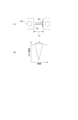
- FIG. 1 is a schematic cross-sectional view of a sensing device used in the method of evaluating the deformability of suspended cells of the present invention.
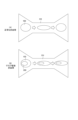
- FIG. 2(A) is a schematic diagram of a detection channel used in a conventional method for evaluating red blood cell deformability
- FIG. 2(B) is a graph showing the ionic current flowing through a sensing device using the detection channel shown in FIG. 2(A).
- FIG. 3(A) is a schematic diagram of a detection channel used in the method for evaluating red blood cell deformability of this embodiment
- FIG. 3(B) and FIG. 3(C) are graphs showing the ionic current flowing through a sensing device using the detection channel shown in FIG. 3(A).
- FIG. 3(A) is a schematic diagram of a detection channel used in the method for evaluating red blood cell deformability of this embodiment
- FIG. 3(B) and FIG. 3(C) are graphs showing the ionic current flowing through a sensing device using the detection channel shown
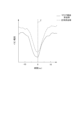
- FIG. 4 is a graph showing the results of measuring the ion current with an ammeter when normal red blood cells and red blood cells infected with malaria are placed in the electrolyte solution of the sensing device shown in FIG.
- FIG. 5(A) is an explanatory diagram illustrating how normal red blood cells pass through the detection channel
- FIG. 5(B) is an explanatory diagram illustrating how red blood cells infected with malaria pass through the detection channel.
- FIG. 6 is an explanatory diagram for explaining an evaluation of the symmetry of an ion current waveform in another embodiment.
- FIG. 7 is a graph showing the results of measuring the ion current with an ammeter when old red blood cells and GA red blood cells are placed in the electrolyte solution of the sensing device shown in FIG.
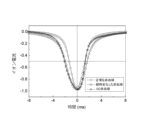
- FIG. 8 is a graph showing the results of measuring the ion current with an ammeter when normal red blood cells, old red blood cells, and GA red blood cells are placed in the electrolyte solution of the sensing device shown in FIG.
- FIG. 9 is a graph showing simulated ion current waveforms for each Young's modulus of the cell membrane.
- the method for evaluating the deformability of suspended cells is a method for evaluating the deformability of suspended cells in an electrolyte solution using a sensing device 1 shown in FIG. 1.
- suspended cells are cells that can float in an electrolyte solution, and include cultured cells that grow in a suspended state in a medium, as well as adherent cells that have been processed to be in a suspended state.
- they are blood cells, and include not only cells with a nucleus such as white blood cells, but also cells without a nucleus such as red blood cells.
- red blood cells an example of evaluating the deformability of red blood cells as suspended cells will be described.
- the "height direction D1", “length direction D2”, and “width direction D3” are defined below as shown in FIG. 1 etc.
- the “length direction D1” is defined as the direction connecting the first tank 5 and the second tank 6 described below, and the “height direction D1", “length direction D2”, and “width direction D3" are perpendicular to each other.
- the sensing device 1 used in the method for evaluating red blood cell deformability of this embodiment (hereinafter simply referred to as the "evaluation method") will be described.
- the sensing device 1 includes a first tank 5 having an input electrode 2 and filled with an electrolyte solution 4, a second tank 6 having an output electrode 3 and filled with the electrolyte solution 4, a detection channel CH that connects the first tank 5 and the second tank 6, an inlet portion 7, and an outlet portion 8.
- the input electrode 2 and the output electrode 3 are arranged in a long cylindrical shape.
- the input electrode 2 and the output electrode 3 are arranged with their longitudinal direction aligned along the height direction D1, and are arranged side by side in the longitudinal direction D2.
- One end of the input electrode 2 is immersed in the electrolyte solution 4 in the first tank 5, and the other end protrudes from the first tank 5.
- One end of the output electrode 3 is immersed in the electrolyte solution 4 in the second tank 6, and the other end protrudes from the second tank 6.
- a low DC voltage output from a DC power source 10 is applied between the input electrode 2 and the output electrode 3.
- an ammeter 11 is provided between the input electrode 2 and the output electrode 3, and the ammeter 11 can measure the ion current flowing between the input electrode 2 and the output electrode 3.
- the first tank 5 and the second tank 6 are separated by an insulating film 9, and the insulating film 9 is provided with a detection channel CH, an inlet portion 7, and an outlet portion 8.
- the detection channel CH is provided between the inlet portion 7 and the outlet portion 8.
- the detection channel CH has a flow path length L1 along the longitudinal direction D2.
- the inlet portion 7 and the detection channel CH communicate with each other via the end of the detection channel CH on the inlet portion 7 side.
- the outlet portion 8 and the detection channel CH communicate with each other via the end of the detection channel CH on the outlet portion 8 side.
- the detection channel CH is provided with a rectangular cross section, and has the same height and width W1 from the end on the inlet portion 7 side to the end on the outlet portion 8 side in the longitudinal direction D2.
- the inlet section 7 connects the first tank 5 to the detection channel CH.
- the outlet section 8 connects the detection channel CH to the second tank 6.
- the inlet section 7 and the outlet section 8 are provided at the same height from one end to the other end in the length direction D2.
- the inlet section 7 and the outlet section 8 are also provided symmetrically in the length direction D2 with the detection channel CH at the center, and are provided so that their width decreases as they approach the detection channel CH.
- Red blood cells 100 are disk-shaped with a diameter of approximately 7 ⁇ m to 8 ⁇ m and a height of 2 ⁇ m to 3 ⁇ m.
- the conventional detection channel CH has a narrow width W2 and a long flow path length L2, which means that it is prone to becoming clogged with the red blood cells 100.
- the width W2 of the detection channel CH is narrowed and the flow path length L2 is lengthened.
- the red blood cells 100 have difficulty passing through the detection channel CH. This is utilized to evaluate the deformability of the red blood cells 100 using the pulse width T2 of the ion current.
- This pulse width T2 of the ion current depends on the above-mentioned deformability, but does not depend on the repair ability, so there is an issue that the repair ability cannot be evaluated.
- the red blood cell 100 When the red blood cell 100 enters the detection channel CH, it deforms from its normal disk shape to an elliptical disk shape that matches the width W1 of the detection channel CH. When the red blood cell 100 leaves the detection channel CH, it returns from its elliptical disk shape to a disk shape. At this time, if the ability to restore is lower than its ability to deform, the red blood cell 100 will have difficulty restoring itself from its elliptical disk shape to its normal disk shape.
- the red blood cell 100 leaves the detection channel CH in an elliptical disk shape that is less likely to inhibit the ionic current, and so the time it takes for the ionic current to return from the minimum value to the steady state is shorter than the time it takes for the ionic current to reach the minimum value from the steady state.
- the deformation when entering the detection channel CH is similar to the repair when leaving the detection channel CH, so as shown in Figure 3 (B), the ion current waveform, with the horizontal axis (first axis) representing time and the vertical axis (second axis) representing ion current, is thought to be symmetrical in the horizontal axis direction (first axis) with respect to axis Z (third axis) that passes through the minimum value of the ion current and is parallel to the vertical axis.
- the sensing device 1 had a detection channel CH with a width W1 of 5 ⁇ m and a flow path length L1 of 10 ⁇ m.
- the electrolyte solution 4 of the sensing device 1 contained normal red blood cells 100 and red blood cells 100 infected with malaria. Phosphate-buffered saline (PBS) was used as the electrolyte solution 4.
- PBS Phosphate-buffered saline
- the normal red blood cells 100 are flexible and easily deformed (high deformability), and are also easily restored from deformation (high restoration ability).
- the red blood cells 100 infected with malaria have a nucleus 200 (see FIG. 5) derived from the malaria parasite inside the red blood cells 100, causing them to lose flexibility.
- red blood cells 100 approaching the end of their life also lose flexibility.
- the malaria-infected red blood cell 100 was made visible by a fluorescent nuclear staining under a fluorescent microscope, and the ion current when a normal red blood cell 100 passed through the detection channel CH and the ion current when a malaria-infected red blood cell 100 passed through the detection channel CH were measured.
- a very small amount of fluorescent nuclear staining was used so as not to cause any effect such as hardening of the red blood cell.
- a voltage of 1.0 V was applied between the input electrode 2 and the output electrode 3 using a 1.0 V DC power supply 10, and the sampling rate of the ion current was set to 200 kHz.
- FIG. 4 the ion current of the normal red blood cell 100 and the ion current of the malaria-infected red blood cell 100 are shifted on the vertical axis to make the graph easier to read.
- the ionic current waveform when a malaria-infected red blood cell 100 passes through the detection channel CH is not symmetrical in the horizontal direction with respect to axis Z, but is asymmetrical, as shown by the solid line in Figure 4.
- the axis Z of the ionic current waveform of a malaria-infected red blood cell is biased to the right side of the drawing in the horizontal direction (i.e., toward the passage of time). This is thought to be because the repair ability of a malaria-infected red blood cell 100 is lower than that of a normal red blood cell.
- the detection channel CH of the sensing device 1 had a width W1 of 10 ⁇ m and a flow path length L1 of 10 ⁇ m.
- Normal red blood cells 100 were contained in the electrolyte solution 4 of the sensing device 1.
- Phosphate buffered saline was used as the electrolyte solution 4.
- the ionic current when the normal red blood cells 100 passed through was measured for 2000 pulses.
- a voltage of 1.0 V was applied between the input electrode 2 and the output electrode 3 using a 1.0 V DC power supply 10, and the sampling rate of the ionic current was set to 200 kHz.
- the most frequent ionic current waveform among the ionic current waveforms for 2000 pulses was symmetrical in the horizontal direction with respect to the axis Z.
- malaria-infected red blood cells 100 with an infection rate of 91.3% were added to the electrolyte solution 4 of the sensing device 1.
- the ionic current was measured for 2000 pulses as the malaria-infected red blood cells 100 passed through.
- the most frequent ionic current waveform of the ionic current waveforms for the 2000 pulses was asymmetric in the horizontal direction with respect to the axis Z.
- the symmetry is determined based on a comparison between a first time T11 from when the ion current becomes equal to or less than the threshold value Ith until the ion current reaches its minimum value, and a second time T12 from when the ion current returns from its minimum value to the threshold value Ith. If the difference (T11-T12) or ratio (T11/T12) between the first time T11 and the second time T12 is equal to or less than a predetermined value, the ion current waveform is evaluated to be symmetrical and no abnormality has occurred in the red blood cell 100.
- the ion current waveform is evaluated to be asymmetrical and the red blood cell 100 is evaluated to be hardened.
- the threshold value Ith is set to be equal to or less than the steady value of the ion current and greater than the minimum value.
- the threshold value Ith is set to be half the peak height H of the ion current, which makes it easier to evaluate the symmetry.
- the axis Z of the ion current waveform is biased to the right, and the repair ability of the red blood cells 100 is evaluated to be lower than their deformation ability.
- the first times T11 and T12 it is also possible to measure the ion current waveform when a large number of red blood cells 100 have passed and calculate the average.
- the symmetry of the ion current waveform is determined, and the deformability of red blood cells is evaluated based on the symmetry. This makes it possible to evaluate the deformability of red blood cells even when using a sensing device 1 that has a wide detection channel and a long flow path length, i.e., one that is less likely to be clogged by red blood cells.
- the symmetry of the ion current waveform is determined based on a comparison between the first time T11 and the second time T12. This makes it possible to easily determine the symmetry of the ion current waveform.
- the present invention is not limited to the above-described embodiment, and can be modified, improved, etc. as appropriate.
- the material, shape, dimensions, number, location, etc. of each component in the above-described embodiment are arbitrary as long as they can achieve the present invention, and are not limited.
- the symmetry of the ion current waveform is determined based on a comparison between the first time T11 and the second time T12, but this is not limited to the above.
- the symmetry of the ion current may be determined based on a comparison of the difference or ratio between an integral value S1 of the difference between the ion current at the first time T11 and a threshold value Ith and an integral value S2 of the difference between the ion current at the second time and a threshold value Ith.
- a difference if it exceeds 0 it is determined to be asymmetric
- a ratio if it exceeds 1 it is determined to be asymmetric.
- the inlet 7 and outlet 8 are provided symmetrically in the length direction, and the ion current waveform when a normal red blood cell 100 passes through the detection channel CH is symmetrical in the horizontal direction, but this is not limited to the above.
- the inlet 7 and outlet 8 do not have to be symmetrical in the length direction.
- the red blood cell 100 can be evaluated by comparing the symmetry in the horizontal direction of the ion current waveform when a normal red blood cell 100 passes through the detection channel CH with the symmetry in the horizontal direction of the ion current waveform when the red blood cell 100 to be evaluated passes through the detection channel CH.
- the inventors conducted the following Tests 3 and 4 to confirm whether the ionic current waveform would become asymmetric even if red blood cells hardened due to causes other than malaria infection.
- the detection channel CH of the sensing device 1 had a width W1 of 4 ⁇ m and a flow path length L1 of 10 ⁇ m.
- the electrolyte solution 4 of the sensing device 1 contained red blood cells 100 that had deteriorated over time several days after blood collection. The ion current was measured when the deteriorated red blood cells 100 passed through the detection channel CH.
- the electrolyte solution 4 of the sensing device 1 contained red blood cells 100 (hereinafter, abbreviated as "GA red blood cells 100”) that had been hardened using glutaraldehyde (hereinafter, abbreviated as "GA”), which is known as a reagent that hardens cells.
- the ion current waveform was measured when the GA red blood cells 100 passed through the detection channel CH. The results are shown in FIG. 7.
- aged red blood cells 100 (hematocrit value 50%, frozen for at least several days after collection) were washed twice (centrifuged at 1500 G for 5 minutes) with phosphate buffered saline (PBS solution), which is the electrolyte solution 4, and a PBS solution was prepared in which 4 x 10⁶ /mL of the washed red blood cells 100 were suspended. 2 ⁇ L of the PBS solution in which the aged red blood cells 100 were suspended was placed in the first tank 5 and the second tank 6 already filled with the PBS solution, and the ion current waveform was measured when the aged red blood cells 100 passed through the detection channel CH.
- PBS solution phosphate buffered saline
- the detection channel CH of the sensing device 1 had a width W1 of 2 ⁇ m and a flow path length L1 of 10 ⁇ m.
- the electrolyte solution 4 of the sensing device 1 contained normal red blood cells 100 of a healthy person. The ion current was measured when the normal red blood cells 100 passed through the detection channel CH.
- the electrolyte solution 4 of the sensing device 1 contained red blood cells 100 that had deteriorated over time, which had been collected for several days or more. The ion current was measured when the deteriorated red blood cells 100 passed through the detection channel CH.
- the electrolyte solution 4 of the sensing device 1 contained red blood cells 100 immersed in glucose (GC; blood glucose) as a model of diabetic red blood cells 100 (hereinafter abbreviated as "GC red blood cells”).
- GC red blood cells a model of diabetic red blood cells 100
- the ion current was measured when the GC red blood cells 100 passed through the detection channel CH. The results are shown in FIG. 8.
- a PBS solution in which healthy human blood (immediately after blood collection) was suspended was used as the electrolyte solution 4 containing normal red blood cells 100.
- 200 ⁇ L of a PBS solution in which 4 ⁇ 10 6 /mL red blood cells 100 deteriorated over time were suspended was used as in the above [Test 3].
- a glucose solution was prepared by adding glucose (final concentration 20%) to a PBSA solution (PBS + 1% human serum albumin). The glucose solution and the PBS solution in which red blood cells 100 deteriorated over time were suspended were mixed at a ratio of 1:1, stirred at 36.5° C. for 5 hours, and then washed twice with PBS (centrifugation at 1500 G for 5 minutes) to prepare an electrolyte solution 4 containing GC red blood cells 100.
- the ion current waveform when a normal red blood cell 100 passes through the detection channel CH is the first time T11 ⁇ the second time T12, and it was confirmed that it is the target.
- the electrolyte solution 4 containing normal red blood cells 100 also contains white blood cells (8-15 ⁇ ) that are larger in diameter than the red blood cells 100 (7-8 ⁇ m), but no clogging of the detection channel CH due to them was observed in the measurement of several hundred pulses. This is thought to be because whole blood contains several million red blood cells 100 per ⁇ L, while white blood cells are less than 1/1000 of the red blood cells 100, at around tens of millions per ⁇ L, and therefore the foreign cells are almost all red blood cells 100 stochastically, so no clogging that would hinder measurement occurred.
- the ion current waveform is asymmetric, with the first time T11 being greater than the second time T12.
- red blood cells 100 are evaluated, but this is not limited to this. A similar evaluation may also be performed on floating cells other than red blood cells (e.g., blood cells such as white blood cells and platelets).
- red blood cells e.g., blood cells such as white blood cells and platelets.
- the inventors performed a simulation using the finite element method on the ion current waveform for each Young's modulus of the cell membrane of suspended cells.
- Suspended cells were modeled as having a cell diameter of 8 ⁇ m and a cell membrane thickness of 80 nm.
- the water pressure in the first tank 5 was set to 10 Pa, and the water pressure in the second tank 6 was set to 0 Pa.
- Fluid-Structure Interaction (FSI) calculations were performed using the Navier-Stokes equation for incompressible fluids and the relationship between stress and strain, and the current value I was calculated from the obtained cell shape-time model using the following equation (1).
- I E ⁇ A(D4)dD ...
- E voltage applied to the input electrode 2 and the output electrode 3 (1.0 V)
- ⁇ electrical conductivity of the electrolyte solution 4 (1.73 S/m)
- A(D) cross-sectional area of the flow channel excluding suspended cells at position D in the length direction D2 in the detection channel CH
- the detection channel CH has a square cross-section, but this is not limited to this.
- the detection channel CH may have any shape that allows suspended cells such as red blood cells to pass through, and may also have a circular cross-section.
- the detection channel CH is designed according to the size of the suspended cells. For example, it is possible to determine the width W1 through which suspended cells can pass without clogging, and design the flow path length L1 so that the symmetry of the ion current waveform can be determined at the determined width W1.
- the width W1 may be designed to be 5 ⁇ m to 30 ⁇ m, and the flow path length L1 to be 1 ⁇ m to 30 ⁇ m.
- the width W1 may be designed to be 5 ⁇ m to 20 ⁇ m, and the flow path length L1 to be 1 ⁇ m to 20 ⁇ m. More preferably, the width W1 may be designed to be 5 ⁇ m to 10 ⁇ m, and the flow path length L1 to be 1 ⁇ m to 10 ⁇ m.
- a first tank (5) provided with an input electrode (2) and filled with an electrolyte solution (4); a second tank (6) provided with an output electrode (3) and filled with the electrolyte solution;
- a method for evaluating the deformability of suspended cells in an electrolyte solution using a sensing device (1) including: In an ion current waveform in which a first axis represents time and a second axis represents a pulsed ion current flowing between the input electrode and the output electrode when the floating cell passes through the detection channel, the symmetry of the first axis direction with respect to a third axis that passes through a minimum value of the ion current and is parallel to the second axis is determined; evaluating the deformability of the suspended cells based on the determination of the symmetry; A method for evaluating the deformability of suspended cells.
- [2] In the method for evaluating the deformability of a suspended cell according to [1], determining the symmetry based on a comparison between a first time from when the ion current becomes equal to or less than a threshold value until the ion current reaches the minimum value and a second time until the ion current returns from the minimum value to the threshold value; A method for evaluating the deformability of suspended cells. [3] In the method for evaluating the deformability of a suspended cell according to [1] or [2], The floating cells are blood cells. A method for evaluating the deformability of suspended cells.
- the present invention provides a method for evaluating the deformability of suspended cells that can evaluate the deformability even when using a sensing device that is less likely to become clogged with red blood cells.
- the present invention which has this effect, is useful as a method for evaluating the deformability of suspended cells.
Landscapes
- Health & Medical Sciences (AREA)
- Life Sciences & Earth Sciences (AREA)
- Chemical & Material Sciences (AREA)
- Physics & Mathematics (AREA)
- General Health & Medical Sciences (AREA)
- Immunology (AREA)
- Pathology (AREA)
- General Physics & Mathematics (AREA)
- Biochemistry (AREA)
- Analytical Chemistry (AREA)
- Engineering & Computer Science (AREA)
- Biomedical Technology (AREA)
- Electrochemistry (AREA)
- Chemical Kinetics & Catalysis (AREA)
- Hematology (AREA)
- Urology & Nephrology (AREA)
- Biophysics (AREA)
- Ecology (AREA)
- Molecular Biology (AREA)
- Medicinal Chemistry (AREA)
- Food Science & Technology (AREA)
- Dispersion Chemistry (AREA)
- Investigating Or Analysing Biological Materials (AREA)
Abstract
センシングデバイス(1)を用いて電解質溶液(4)中の赤血球(100)の変形能を評価する。横軸を時間、縦軸を赤血球(100)が検出チャンネルCHを通過する際の入力電極(2)及び出力電極(3)間に流れるパルス状のイオン電流としたイオン電流波形において、イオン電流の最小値を通り、縦軸と平行な軸Zに対する横軸方向の対称性を判定し、対称性の判定に基づいて赤血球(100)の変形能を評価する。
Description
本発明は、浮遊細胞の変形能評価方法、に関する。
赤血球の変形能を評価する方法として、センシングデバイスを用いたものが提案されている(非特許文献1)。非特許文献1の評価方法は、電解質溶液を満たした微細な貫通孔(検出チャンネル)を介して流れるイオン電流を計測し、電解質溶液中の赤血球の変形能を評価する手法である。赤血球が検出チャンネルを通過すると、イオン電流の流れを阻害するため、イオン電流がパルス状に変化する。検出チャンネルの幅は赤血球よりも狭く設けられ、赤血球は検出チャンネルを通過する際に変形する。赤血球が硬くなると変形しにくくなるため検出チャンネルの通過時間が延び、イオン電流のパルス幅が長くなる。このイオン電流のパルス幅に基づいて赤血球の変形能を評価する。
X.Yang,Z.Chen,J.Miao,L.Cui,W.Guan, "High-throughput and label-free parasitemia quantification and stage differentiation for malaria-infected red blood cells" Biosens.Bioelectron. 98 (2017) 408-414
上述した従来の評価方法では、検出チャンネルの幅が赤血球の直径よりもかなり狭い。しかも、イオン電流のパルス幅に基づいて変形能を評価しているため、精度よく評価するためには、検出チャンネルの長さを長くしてパルス幅を長くする必要があった。このため、検出チャンネルには赤血球がつまりやすい、という課題があった。検出チャンネルに赤血球がつまると、赤血球の変形能を評価することができなくなる。
本発明は、上述した事情に鑑みてなされたものであり、その目的は、赤血球がつまりにくいセンシングデバイスを用いても変形能力を評価できる浮遊細胞の変形能評価方法を提供することにある。
前述した目的を達成するために、本発明に係る浮遊細胞の変形能評価方法は、下記[1]~[3]を特徴としている。
[1]
入力電極が設けられ、電解質溶液が満たされた第1槽と、
出力電極が設けられ、前記電解質溶液が満たされた第2槽と、
前記第1槽及び前記第2槽を連通する検出チャンネルと、を備えた
センシングデバイスを用いて前記電解質溶液中の浮遊細胞の変形能を評価する浮遊細胞の変形能評価方法であって、
第1軸を時間、第2軸を前記浮遊細胞が前記検出チャンネルを通過する際の前記入力電極及び前記出力電極間に流れるパルス状のイオン電流としたイオン電流波形において、前記イオン電流の最小値を通り、前記第2軸と平行な第3軸に対する第1軸方向の対称性を判定し、
前記対称性の判定に基づいて前記浮遊細胞の変形能を評価する、
浮遊細胞の変形能評価方法であること。
[2]
[1]に記載の浮遊細胞の変形能評価方法において、
前記イオン電流が閾値以下となった時間から前記イオン電流が前記最小値に達するまでの第1時間と、前記イオン電流が前記最小値から前記閾値に戻るまでの第2時間と、の比較に基づいて、前記対称性を判定する、
浮遊細胞の変形能評価方法であること。
[3]
[1]又は[2]に記載の浮遊細胞の変形能評価方法において、
前記浮遊細胞は、血液細胞である、
浮遊細胞の変形能評価方法であること。
[1]
入力電極が設けられ、電解質溶液が満たされた第1槽と、
出力電極が設けられ、前記電解質溶液が満たされた第2槽と、
前記第1槽及び前記第2槽を連通する検出チャンネルと、を備えた
センシングデバイスを用いて前記電解質溶液中の浮遊細胞の変形能を評価する浮遊細胞の変形能評価方法であって、
第1軸を時間、第2軸を前記浮遊細胞が前記検出チャンネルを通過する際の前記入力電極及び前記出力電極間に流れるパルス状のイオン電流としたイオン電流波形において、前記イオン電流の最小値を通り、前記第2軸と平行な第3軸に対する第1軸方向の対称性を判定し、
前記対称性の判定に基づいて前記浮遊細胞の変形能を評価する、
浮遊細胞の変形能評価方法であること。
[2]
[1]に記載の浮遊細胞の変形能評価方法において、
前記イオン電流が閾値以下となった時間から前記イオン電流が前記最小値に達するまでの第1時間と、前記イオン電流が前記最小値から前記閾値に戻るまでの第2時間と、の比較に基づいて、前記対称性を判定する、
浮遊細胞の変形能評価方法であること。
[3]
[1]又は[2]に記載の浮遊細胞の変形能評価方法において、
前記浮遊細胞は、血液細胞である、
浮遊細胞の変形能評価方法であること。
本発明によれば、赤血球がつまりにくいセンシングデバイスを用いて変形能力を評価できる浮遊細胞の変形能評価方法を提供することができる。
以上、本発明について簡潔に説明した。更に、以下に説明される発明を実施するための形態(以下、「実施形態」という。)を添付の図面を参照して通読することにより、本発明の詳細は更に明確化されるであろう。
本発明に関する具体的な実施形態について、各図を参照しながら以下に説明する。本発明は浮遊細胞の変形能評価方法は、図1に示すセンシングデバイス1を用いて電解質溶液中の浮遊細胞の変形能を評価する方法である。ここで、浮遊細胞は、電解質溶液中を浮遊できる細胞であり、培地中で浮遊した状態で増殖する培養細胞のほか、付着性の細胞を処理して浮遊状態とした細胞を含む。好ましくは、血液細胞であり、白血球などの核を有する細胞だけでなく、赤血球など核なしの細胞も含む。以下の実施形態においては、浮遊細胞としての赤血球の変形能を評価する例について説明する。
以下、説明の便宜上、図1等に示すように、「高さ方向D1」、「長さ方向D2」及び「幅方向D3」を定義する。「長さ方向D1」は後述する第1槽5と第2槽6とを連通する方向として定義され、「高さ方向D1」、「長さ方向D2」及び「幅方向D3」は、互いに直交している。
まず、本実施形態の赤血球の変形能評価方法(以下、単に「評価方法」と略記する)に用いられるセンシングデバイス1について説明する。図1に示すように、センシングデバイス1は、入力電極2が設けられ、電解質溶液4が満たされた第1槽5と、出力電極3が設けられ、電解質溶液4が満たされた第2槽6と、第1槽5及び第2槽6を連通する検出チャンネルCH、入口部7及び出口部8と、を備えている。
入力電極2及び出力電極3は、長尺な円柱状に設けられている。入力電極2及び出力電極3は、長手方向が高さ方向D1に沿って配置され、長さ方向D2に並べて配置される。入力電極2は、一端が第1槽5内の電解質溶液4内に浸され、他端が第1槽5から突出している。出力電極3は、一端が第2槽6内の電解質溶液4内に浸され、他端が第2槽6から突出している。入力電極2及び出力電極3間には、直流電源10から出力される直流の低電圧が印加される。また、入力電極2及び出力電極3間には、電流計11が設けられ、電流計11により入力電極2及び出力電極3間に流れるイオン電流を計測することができる。
本実施形態では、第1槽5及び第2槽6は絶縁体膜9により仕切られ、絶縁体膜9に検出チャンネルCH、入口部7及び出口部8が設けられている。検出チャンネルCHは、入口部7及び出口部8との間に設けられている。検出チャンネルCHは、長さ方向D2に沿った流路長さL1を有している。入口部7と検出チャンネルCHとは検出チャンネルCHの入口部7側の端部を介して連通する。出口部8と検出チャンネルCHとは検出チャンネルCHの出口部8側の端部を介して連通する。検出チャンネルCHは、断面四角形状に設けられ、長さ方向D2の入口部7側の端部から出口部8側の端部に亘って高さと幅W1が同じに設けられている。
入口部7は、第1槽5と検出チャンネルCHとを連通する。出口部8は、検出チャンネルCHと第2槽6とを連通する。入口部7及び出口部8は、長さ方向D2の一端から他端に亘って同じ高さに設けられている。また、入口部7及び出口部8は、検出チャンネルCHを中心に長さ方向D2に対称に設けられ、検出チャンネルCHに近づくに従って幅が小さくなるように設けられている。
次に、上述した図1に示すセンシングデバイス1を用いて電解質溶液4中の赤血球の変形能を評価する方法について説明する。入力電極2及び出力電極3間に低電圧を印加すると、入力電極2からのイオン電流は、検出チャンネルCHを通って出力電極3に向かって流れる。このとき、図2及び図3に示すように、電解質溶液4中の赤血球が検出チャンネルCHを通ると、イオン電流の流れが阻害され、イオン電流が一時的に小さくなり、パルス状のイオン電流が検出される。本実施形態及び背景技術で説明した従来の評価方法は、上記イオン電流に基づいて赤血球の変形能を評価する。
次に、本発明者らは従来の評価方法について考えてみた。赤血球100は、円盤状であり、直径約7μm~8μm、高さ2μm~3μmである。従来の評価方法で用いられる検出チャンネルCHは、図2に示すように、幅W2と高さが赤血球100の直径よりもかなり小さい5μm(W2=5μm)、流路長さL2が45μm(L2=45μm)に設けられている。従来の検出チャンネルCHは、幅W2が狭く、流路長さL2も長いため、赤血球100がつまりやすい、という課題がある。
従来の評価方法では、検出チャンネルCHの幅W2を狭く流路長さL2を長くして、赤血球100の変形能力が低下すると、赤血球100が検出チャンネルCHを通りにくくなることを利用して、イオン電流のパルス幅T2により赤血球100の変形能の評価を行っている。このイオン電流のパルス幅T2は、上述した変形能力に依存するが、修復能力には依存しないため、修復能力の評価ができていない、という課題がある。
発明者らは、これら課題を解決すべく、鋭意探求した結果、図3(A)に示すように、流路長さL1を従来の検出チャンネルCHの長さL2(=45μm)よりも短くすると、好ましくは検出チャンネルCHの幅W1を従来の検出チャンネルCHの幅W2(=5μm)よりも広くすると、赤血球100のつまりを低減し、イオン電流が定常値から最小値に達するまでが変形能力に応じ、最小値から定常値に戻るまでが修復能力に依存して、修復能力の評価を行えるのではないかと考えた。
赤血球100は、検出チャンネルCHに入る際に通常の円盤状から検出チャンネルCHの幅W1に合わせた楕円盤状に変形する。また、赤血球100は、検出チャンネルCHを出る際に楕円盤状から円盤状に修復する。このとき、修復能力が変形能力より低くなると、赤血球100は楕円盤状から通常の円盤状に修復しにくくなる。このため、イオン電流を阻害しにくい楕円盤状のまま検出チャンネルCH外にでるため、イオン電流が定常値から最小値に達するまでの時間よりも、最小値から定常値に戻るまでの時間が短くなる。
そして、赤血球100が正常であり、変形能力と修復能力とが同じ場合、検出チャンネルCHに入る時の変形と、検出チャンネルCHからでるときの修復と、が同程度であるため、図3(B)に示すように、横軸(第1軸)を時間、縦軸(第2軸)をイオン電流としたイオン電流波形が、イオン電流の最小値を通り縦軸に平行な軸Z(第3軸)に対する横軸方向(第1軸方向)が対称となる、と考えた。
また、赤血球100に異常が生じ、変形能力と修復能力とに偏りが生じた場合、図3(C)に示すように、イオン電流波形が、軸Zに対して横軸方向に対称とならない、と考えた。すなわち、修復能力が変形能力より低いと、図3(C)に示すように、イオン電流波形の軸Zが右側(時間が経過する側)に偏る。このことを利用して、イオン電流波形の軸Zの横軸方向の対称性に基づいて赤血球100の評価を行えるのではないか、と考えた。
この考えを検証すべく下記の試験1を行った。
[試験1]
センシングデバイス1の検出チャンネルCHとしては、幅W1=5μm、流路長さL1=10μmのものを用いた。このセンシングデバイス1の電解質溶液4に正常な赤血球100と、マラリアに感染した赤血球100と、を含ませた。電解質溶液4としては、リン酸緩衝生理食塩水(phosphate-buffered saline,PBS)を使用した。正常の赤血球100は柔軟であり、変形しやすく(変形能が高く)、変形からの修復も容易である(修復能が高い)。一方、マラリアに感染した赤血球100は、赤血球100内にマラリア原虫由来の核200(図5参照)ができ、柔軟性が失われることが知られている。また、寿命が近づいた赤血球100も柔軟性が失われることが知られている。そして、蛍光核染色でマラリアに感染した赤血球100を蛍光顕微鏡で可視化できるようにし、正常な赤血球100が検出チャンネルCHを通過したときのイオン電流と、マラリアに感染した赤血球100が検出チャンネルCHを通過したときのイオン電流と、を測定した。なお、蛍光核染色は、赤血球を固くするなどの影響を与えない程度のごく少量を用いた。また、この測定においては、1.0Vの直流電源10を用いて、入力電極2,出力電極3間に1.0Vの電圧を印加し、イオン電流のサンプリングレートを200kHzとした。測定結果を図4に示す。図4においては、正常な赤血球100のイオン電流と、マラリアに感染した赤血球100のイオン電流と、は縦軸をずらしてグラフが見やすいようにしている。
センシングデバイス1の検出チャンネルCHとしては、幅W1=5μm、流路長さL1=10μmのものを用いた。このセンシングデバイス1の電解質溶液4に正常な赤血球100と、マラリアに感染した赤血球100と、を含ませた。電解質溶液4としては、リン酸緩衝生理食塩水(phosphate-buffered saline,PBS)を使用した。正常の赤血球100は柔軟であり、変形しやすく(変形能が高く)、変形からの修復も容易である(修復能が高い)。一方、マラリアに感染した赤血球100は、赤血球100内にマラリア原虫由来の核200(図5参照)ができ、柔軟性が失われることが知られている。また、寿命が近づいた赤血球100も柔軟性が失われることが知られている。そして、蛍光核染色でマラリアに感染した赤血球100を蛍光顕微鏡で可視化できるようにし、正常な赤血球100が検出チャンネルCHを通過したときのイオン電流と、マラリアに感染した赤血球100が検出チャンネルCHを通過したときのイオン電流と、を測定した。なお、蛍光核染色は、赤血球を固くするなどの影響を与えない程度のごく少量を用いた。また、この測定においては、1.0Vの直流電源10を用いて、入力電極2,出力電極3間に1.0Vの電圧を印加し、イオン電流のサンプリングレートを200kHzとした。測定結果を図4に示す。図4においては、正常な赤血球100のイオン電流と、マラリアに感染した赤血球100のイオン電流と、は縦軸をずらしてグラフが見やすいようにしている。
正常な赤血球100が検出チャンネルCHを通過したときのイオン電流波形は、図4中の一点鎖線で示すように、軸Zに対して横軸方向に対称となることが分かった。これは、図5(A)に示すように、正常な赤血球100の場合、修復能力が高いからであると考えられる。
これに対して、マラリアに感染した赤血球100が検出チャンネルCHを通過したときのイオン電流波形は、図4中の実線で示すように、軸Zに対して横軸方向に対称となっておらず、非対称であることが分かった。マラリアに感染した赤血球のイオン電流波形の軸Zは、横軸方向の図面右側(つまり、時間が経過する方)に偏っている。これは、マラリアに感染した赤血球100は修復能力が正常赤血球よりも低いためと考えられる。
次に、本発明者らは、上記結果の再現性を確認すべく、下記の試験2を行った。
[試験2]
センシングデバイス1の検出チャンネルCHとしては、幅W1=10μm、流路長さL1=10μmのものを用いた。このセンシングデバイス1の電解質溶液4に正常な赤血球100を含ませた。電解質溶液4としては、リン酸緩衝生理食塩水を使用した。そして、正常な赤血球100が通過する際のイオン電流を2000パルス分計測した。この測定においては、1.0Vの直流電源10を用いて、入力電極2,出力電極3間に1.0Vの電圧を印加し、イオン電流のサンプリングレートを200kHzとした。測定した結果、2000パルス分のイオン電流波形のうち、最も頻度の高いイオン電流波形が軸Zに対して横軸方向に対称になることが確認することができた。
センシングデバイス1の検出チャンネルCHとしては、幅W1=10μm、流路長さL1=10μmのものを用いた。このセンシングデバイス1の電解質溶液4に正常な赤血球100を含ませた。電解質溶液4としては、リン酸緩衝生理食塩水を使用した。そして、正常な赤血球100が通過する際のイオン電流を2000パルス分計測した。この測定においては、1.0Vの直流電源10を用いて、入力電極2,出力電極3間に1.0Vの電圧を印加し、イオン電流のサンプリングレートを200kHzとした。測定した結果、2000パルス分のイオン電流波形のうち、最も頻度の高いイオン電流波形が軸Zに対して横軸方向に対称になることが確認することができた。
また、センシングデバイス1の電解質溶液4に感染率91.3%のマラリア感染赤血球100を含ませた。そして、マラリア感染赤血球100が通過する際のイオン電流を2000パルス分測定した。結果、2000パルス分のイオン電流波形のうち、最も頻度の高いイオン電流波形が軸Zに対して横軸方向に非対称になることを確認することができた。
上述した試験からイオン電流波形において、軸Zに対する横軸方向の対称性を判定し、その対称性に基づいて赤血球100の変形能を評価できることが分かった。このことを利用して、本実施形態の赤血球100の評価方法においては、イオン電流波形において、軸Zに対する横軸方向の対称性を判定し、その対称性に基づいて赤血球100の変形能を評価する。
次に、イオン電流波形の対称性の判定方法について説明する。図3に示すように、イオン電流が閾値Ith以下となった時間からイオン電流が最小値に達するまでの第1時間T11と、イオン電流が最小値から閾値Ithに戻るまでの第2時間T12と、の比較に基づいて、対称性を判定する。この第1時間T11と第2時間T12との差分(T11-T12)又は比(T11/T12)が所定値以下であれば、イオン電流波形が対称であり、赤血球100に異常が生じていないと評価する。一方、第1時間T11と第2時間T12との差分(T11-T12)又は比(T11/T12)が所定値を超えていれば、イオン電流波形が非対称であり、赤血球100が硬くなっていると評価する。なお、閾値Ithは、イオン電流の定常値以下、最小値より大きく設定される。好ましくは、イオン電流のピーク高さHの半分に設定すると、対称性の評価が容易となる。
イオン電流が非対称と判定した際に、図3(C)に示すように、第1時間T11>第2時間T12であれば、イオン電流波形の軸Zが右側に偏り、赤血球100の修復能力が変形能力よりも低いと評価する。ただし、第1時間T11,T12については、ばらつきや計測誤差などもあるため、多数個の赤血球100が通過したときのイオン電流波形を測定し、その平均を求めてもよい。
上述した実施形態によれば、イオン電流波形の対称性を判定し、対称性に基づいて赤血球の変形能を評価している。これにより、幅が広く、流路長さが長い検出チャンネル、すなわち赤血球がつまりにくいセンシングデバイス1を用いても、赤血球の変形能を評価することができる。
上述した実施形態によれば、第1時間T11と第2時間T12との比較に基づいてイオン電流波形の対称性を判定している。これにより、簡単にイオン電流波形の対称性を判定することができる。
なお、本発明は、上述した実施形態に限定されるものではなく、適宜、変形、改良、等が可能である。その他、上述した実施形態における各構成要素の材質、形状、寸法、数、配置箇所、等は本発明を達成できるものであれば任意であり、限定されない。
上述した実施形態によれば、第1時間T11と第2時間T12との比較に基づいてイオン電流波形の対称性を判定していたが、これに限ったものではない。例えば、図6に示すように、第1時間T11におけるイオン電流と閾値Ithとの差分の積分値S1と、第2時間におけるイオン電流と閾値Ithとの差分の積分値S2と、の差分又は比の比較に基づいてイオン電流の対称性を判定するようにしてもよい。具体的には、差分の場合は0を越えてれば非対称と判定し、比の場合は、1を越えていれば非対称と判定することが考えられる。
上述した実施形態によれば、入口部7及び出口部8を長さ方向に対称に設け、正常な赤血球100が検出チャンネルCHを通過したときのイオン電流波形を横軸方向に対称にしていたが、これに限ったものではない。入口部7及び出口部8は長さ方向に対称でなくてもよい。この場合、正常な赤血球100が検出チャンネルCHを通過したときのイオン電流波形の横軸方向の対称性と、判定対象となる赤血球100が検出チャンネルCHを通過したときのイオン電流波形の横軸方向の対称性とを比較して、赤血球100の評価を行なえばよい。
上述した実施形態によれば、[試験1],[試験2]により、マラリア感染した赤血球100が検出チャンネルCHを通過したときのイオン電流波形が非対称であることを確認した。しかしながら、赤血球が硬くなる原因は、マラリア感染だけではない。例えば、糖尿病などの病気によっても赤血球100が硬くなることが知られている。また、経時劣化によっても赤血球100が硬くなることが知られている。
本発明者らは、マラリア感染以外に起因して赤血球が硬くなった場合でも、イオン電流波形が非対称となるか確認すべく、下記の試験3、試験4を行った。
[試験3]
センシングデバイス1の検出チャンネルCHとしては、幅W1=4μm、流路長さL1=10μmのものを用いた。このセンシングデバイス1の電解質溶液4に採血後数日以上経過して経時劣化した赤血球100を含ませた。そして、経時劣化した赤血球100が検出チャンネルCHを通過したときのイオン電流を測定した。また、センシングデバイス1の電解質溶液4に細胞を硬化する試薬として知られているグルタルアルデヒド(以下、「GA」と略記)を用いて硬化させた赤血球100(以下、「GA赤血球100」と略記)を含ませた。そして、GA赤血球100が検出チャンネルCHを通過したときのイオン電流波形を計測した。結果を図7に示す。
センシングデバイス1の検出チャンネルCHとしては、幅W1=4μm、流路長さL1=10μmのものを用いた。このセンシングデバイス1の電解質溶液4に採血後数日以上経過して経時劣化した赤血球100を含ませた。そして、経時劣化した赤血球100が検出チャンネルCHを通過したときのイオン電流を測定した。また、センシングデバイス1の電解質溶液4に細胞を硬化する試薬として知られているグルタルアルデヒド(以下、「GA」と略記)を用いて硬化させた赤血球100(以下、「GA赤血球100」と略記)を含ませた。そして、GA赤血球100が検出チャンネルCHを通過したときのイオン電流波形を計測した。結果を図7に示す。
詳しく説明すると、経時劣化した赤血球100(ヘマトクリット値50%、採決後数日以上冷凍保存)を電解質溶液4であるリン酸緩衝生理食塩水(PBS溶液)で2度洗浄(1500G、5分間の遠心)し、洗浄した4×10⁶/mLの赤血球100を懸濁させたPBS溶液を調整した。この経年劣化した赤血球100を懸濁させたPBS溶液2μLを、既にPBS溶液が充填された第1槽5及び第2槽6内に入れて、経年劣化した赤血球100が検出チャンネルCHを通過したときのイオン電流波形を測定した。
また、赤血球100を懸濁させたPBS溶液200μLに10%GAを2μL添加して0.1%GA濃度にしたもの2μLを、既にPBS溶液が充填された第1槽5及び第2槽6内に入れて、GA赤血球100が検出チャンネルCHを通過したときのイオン電流波形を測定した。
図7に示すように、経時劣化した赤血球100が検出チャンネルCHを通過したときのイオン電流波形は、第1時間T11>第2時間T12となっており、非対称になることを確認することができた。また、GA赤血球100が検出チャンネルCHを通過したときのイオン電流波形も、第1時間T11>第2時間T12となっており、非対称になることを確認することができた。
[試験4]
センシングデバイス1の検出チャンネルCHとしては、幅W1=2μm、流路長さL1=10μmのものを用いた。このセンシングデバイス1の電解質溶液4に健常人の正常な赤血球100を含ませた。そして、正常な赤血球100が検出チャンネルCHを通過したときのイオン電流を測定した。また、センシングデバイス1の電解質溶液4に採血後数日以上経過した経時劣化した赤血球100を含ませた。そして、経年劣化した赤血球100が検出チャンネルCHを通過したときのイオン電流を測定した。また、また、センシングデバイス1の電解質溶液4に糖尿病の赤血球100のモデルとしてグルコース(GC;血糖)に浸した赤血球100(以下、「GC赤血球」と略記)を含ませた。そして、GC赤血球100が検出チャンネルCHを通過したときのイオン電流を測定した。結果を図8に示す。
センシングデバイス1の検出チャンネルCHとしては、幅W1=2μm、流路長さL1=10μmのものを用いた。このセンシングデバイス1の電解質溶液4に健常人の正常な赤血球100を含ませた。そして、正常な赤血球100が検出チャンネルCHを通過したときのイオン電流を測定した。また、センシングデバイス1の電解質溶液4に採血後数日以上経過した経時劣化した赤血球100を含ませた。そして、経年劣化した赤血球100が検出チャンネルCHを通過したときのイオン電流を測定した。また、また、センシングデバイス1の電解質溶液4に糖尿病の赤血球100のモデルとしてグルコース(GC;血糖)に浸した赤血球100(以下、「GC赤血球」と略記)を含ませた。そして、GC赤血球100が検出チャンネルCHを通過したときのイオン電流を測定した。結果を図8に示す。
詳しく説明すると、健常人血液(採血直後)を懸濁したPBS溶液を正常な赤血球100を含ませた電解質溶液4とした。経時劣化した赤血球100を含ませた電解質溶液4としては、上記[試験3]と同様に4×10⁶/mLの経時劣化した赤血球100を懸濁させたPBS溶液200μLを用いた。また、PBSA溶液(PBS+1%ヒト血清アルブミン)にグルコース(終濃度20%)を加えて、グルコース溶液を作成する。グルコース溶液と、経時劣化した赤血球100を懸濁させたPBS溶液と、を1:1で混合し、36.5℃で、5時間攪拌した後、PBSで2度洗浄(1500G、5分間の遠心)して、GC赤血球100を含ませた電解質溶液4とした。
図8に示すように、正常な赤血球100が検出チャンネルCHを通過したときのイオン電流波形は、第1時間T11≒第2時間T12となっており、対象になっていることを確認することができた。正常な赤血球100を含む電解質溶液4には、赤血球100(7-8μm)より径の大きな白血球等(8-15μ)も含まれているが、それらによる検出チャンネルCHのつまりは数百パルスの計測では見られなかった。これは全血で赤血球100は数百万個/μL含まれるのに対し、白血球は数千万個/μL程度の赤血球100の1/1000以下であり、通貨細胞は確率的にほぼ赤血球100となり、計測の障害となるつまりが生じなかったためと考えられる。
また、経時劣化した赤血球100,糖尿病の赤血球100のモデルであるGC赤血球100が検出チャンネルCHを通過したときのイオン電流波形も、第1時間T11>第2時間T12となっており、非対称になることを確認することができた。
これらの結果から、本手法が全血のPBS溶液の計測という簡便な評価方法でも、正常な赤血球100に対して、経時劣化した赤血球100や糖化による赤血球100の変化能低下を評価できることが分かった。
また、上述した実施形態では、赤血球100について評価していたが、これに限ったものではない。赤血球以外の浮遊細胞(例えば白血球、血小板などの血液細胞)についても同様の評価を行うようにしてもよい。
本発明者らは、上述した変形能の評価方法が、赤血球以外の浮遊細胞にも適用できるか確認すべく、浮遊細胞の細胞膜のヤング率ごとのイオン電流波形について有限要素法によるシミュレーションを行った。このシミュレーションでは、検出チャンネルCHを幅W1=10μm、流路長さL1=10μmとした。また、細胞径8μm、細胞膜厚80nmの浮遊細胞としてモデル化した。また、第1槽5の水圧を10Pa、第2槽6の水圧を0Paとした。非圧縮性流体についてのナビエストークス方程式、応力とひずみの関係式を用いて、流体-構造連成(Fluid-Structure Interaction、FSI)計算を行い、得られた細胞形状-時間モデルから、下記の式(1)によって電流値Iを求めた。I=Eσ∫A(D4)dD …(1)E:入力電極2及び出力電極3に印加する電圧(1.0V)σ:電解質溶液4の電気伝導率(1.73S/m)A(D):検出チャンネルCH内の長さ方向D2の位置Dにおける浮遊細胞を除いた流路断面積
シミュレーションした結果を図9に示す。同図に示すように、ヤング率が高いほど修復力が低くなり、修復力が低いほど右側に傾くことが分かった。すなわち、イオン電流波形は、細胞膜のヤング率に応じて変形するため、赤血球以外の浮遊細胞にも上記変形能の評価方法を適用できることが確認できた。
上述した実施形態によれば、検出チャンネルCHとしては断面四角形状のものを用いていたが、これに限ったものではない。検出チャンネルCHとしては、赤血球などの浮遊細胞を通すことができる形状であればよく、断面円状であってもよい。
上述した実施形態によれば、幅W1=5μmまたは10μm、流路長さL1=10μmの検出チャンネルCHを用いていたが、これに限ったものではない。検出チャンネルCHは浮遊細胞のサイズに合わせて設計される。例えば、浮遊細胞が詰まらずに通過する幅W1を求め、求めた幅W1においてイオン電流波形の対称性の判定が可能となる流路長さL1に設計することが考えられる。赤血球の場合は、幅W1を5μm~30μm、流長さL1を1μm~30μmに設計してもよい。より好ましくは、幅W1を5μm~20μm、流路長さL1を1μm~20μmに設計してもよい。より好ましくは、幅W1を5μm~10μm、流路長さL1を1μm~10μmに設計してもよい。
ここで、上述した本発明に係る浮遊細胞の変形能評価方法の実施形態の特徴をそれぞれ以下[1]~[3]に簡潔に纏めて列記する。
[1]
入力電極(2)が設けられ、電解質溶液(4)が満たされた第1槽(5)と、
出力電極(3)が設けられ、前記電解質溶液が満たされた第2槽(6)と、
前記第1槽及び前記第2槽を連通する検出チャンネル(CH)と、を備えた
センシングデバイス(1)を用いて前記電解質溶液中の浮遊細胞の変形能を評価する浮遊細胞の変形能評価方法であって、
第1軸を時間、第2軸を前記浮遊細胞が前記検出チャンネルを通過する際の前記入力電極及び前記出力電極間に流れるパルス状のイオン電流としたイオン電流波形において、前記イオン電流の最小値を通り、前記第2軸と平行な第3軸に対する第1軸方向の対称性を判定し、
前記対称性の判定に基づいて前記浮遊細胞の変形能を評価する、
浮遊細胞の変形能評価方法。
[2]
[1]に記載の浮遊細胞の変形能評価方法において、
前記イオン電流が閾値以下となった時間から前記イオン電流が前記最小値に達するまでの第1時間と、前記イオン電流が前記最小値から前記閾値に戻るまでの第2時間と、の比較に基づいて、前記対称性を判定する、
浮遊細胞の変形能評価方法。
[3]
[1]又は[2]に記載の浮遊細胞の変形能評価方法において、
前記浮遊細胞は、血液細胞である、
浮遊細胞の変形能評価方法。
入力電極(2)が設けられ、電解質溶液(4)が満たされた第1槽(5)と、
出力電極(3)が設けられ、前記電解質溶液が満たされた第2槽(6)と、
前記第1槽及び前記第2槽を連通する検出チャンネル(CH)と、を備えた
センシングデバイス(1)を用いて前記電解質溶液中の浮遊細胞の変形能を評価する浮遊細胞の変形能評価方法であって、
第1軸を時間、第2軸を前記浮遊細胞が前記検出チャンネルを通過する際の前記入力電極及び前記出力電極間に流れるパルス状のイオン電流としたイオン電流波形において、前記イオン電流の最小値を通り、前記第2軸と平行な第3軸に対する第1軸方向の対称性を判定し、
前記対称性の判定に基づいて前記浮遊細胞の変形能を評価する、
浮遊細胞の変形能評価方法。
[2]
[1]に記載の浮遊細胞の変形能評価方法において、
前記イオン電流が閾値以下となった時間から前記イオン電流が前記最小値に達するまでの第1時間と、前記イオン電流が前記最小値から前記閾値に戻るまでの第2時間と、の比較に基づいて、前記対称性を判定する、
浮遊細胞の変形能評価方法。
[3]
[1]又は[2]に記載の浮遊細胞の変形能評価方法において、
前記浮遊細胞は、血液細胞である、
浮遊細胞の変形能評価方法。
本発明を詳細にまた特定の実施態様を参照して説明したが、本発明の精神と範囲を逸脱することなく様々な変更や修正を加えることができることは当業者にとって明らかである。
本出願は、2023年6月16日出願の日本特許出願(特願2023-099478)に基づくものであり、その内容はここに参照として取り込まれる。
本発明によれば、赤血球がつまりにくいセンシングデバイスを用いても変形能力を評価できる浮遊細胞の変形能評価方法を提供することができる。この効果を奏する本発明は、浮遊細胞の変形能評価方法に関して有用である。
1 センシングデバイス
2 入力電極
3 出力電極
4 電解質溶液
5 第1槽
6 第2槽
100 赤血球(浮遊細胞)
CH 検出チャンネル
Ith 閾値
T11 第1時間
T12 第2時間
Z 軸(第3軸)
2 入力電極
3 出力電極
4 電解質溶液
5 第1槽
6 第2槽
100 赤血球(浮遊細胞)
CH 検出チャンネル
Ith 閾値
T11 第1時間
T12 第2時間
Z 軸(第3軸)
Claims (3)
- 入力電極が設けられ、電解質溶液が満たされた第1槽と、
出力電極が設けられ、前記電解質溶液が満たされた第2槽と、
前記第1槽及び前記第2槽を連通する検出チャンネルと、を備えた
センシングデバイスを用いて前記電解質溶液中の浮遊細胞の変形能を評価する浮遊細胞の変形能評価方法であって、
第1軸を時間、第2軸を前記浮遊細胞が前記検出チャンネルを通過する際の前記入力電極及び前記出力電極間に流れるパルス状のイオン電流としたイオン電流波形において、前記イオン電流の最小値を通り、前記第2軸と平行な第3軸に対する第1軸方向の対称性を判定し、
前記対称性の判定に基づいて前記浮遊細胞の変形能を評価する、
浮遊細胞の変形能評価方法。 - 請求項1に記載の浮遊細胞の変形能評価方法において、
前記イオン電流が閾値以下となった時間から前記イオン電流が前記最小値に達するまでの第1時間と、前記イオン電流が前記最小値から前記閾値に戻るまでの第2時間と、の比較に基づいて、前記対称性を判定する、
浮遊細胞の変形能評価方法。 - 請求項1又は2に記載の浮遊細胞の変形能評価方法において、
前記浮遊細胞は、血液細胞である、
浮遊細胞の変形能評価方法。
Priority Applications (1)
| Application Number | Priority Date | Filing Date | Title |
|---|---|---|---|
| JP2025528008A JPWO2024257854A1 (ja) | 2023-06-16 | 2024-06-14 |
Applications Claiming Priority (2)
| Application Number | Priority Date | Filing Date | Title |
|---|---|---|---|
| JP2023099478 | 2023-06-16 | ||
| JP2023-099478 | 2023-06-16 |
Publications (1)
| Publication Number | Publication Date |
|---|---|
| WO2024257854A1 true WO2024257854A1 (ja) | 2024-12-19 |
Family
ID=93852195
Family Applications (1)
| Application Number | Title | Priority Date | Filing Date |
|---|---|---|---|
| PCT/JP2024/021668 Ceased WO2024257854A1 (ja) | 2023-06-16 | 2024-06-14 | 浮遊細胞の変形能評価方法 |
Country Status (2)
| Country | Link |
|---|---|
| JP (1) | JPWO2024257854A1 (ja) |
| WO (1) | WO2024257854A1 (ja) |
Citations (3)
| Publication number | Priority date | Publication date | Assignee | Title |
|---|---|---|---|---|
| JPH01196566A (ja) * | 1988-02-01 | 1989-08-08 | Advance Co Ltd | 細胞変形能測定装置 |
| WO2016063858A1 (ja) * | 2014-10-20 | 2016-04-28 | 国立大学法人名古屋大学 | 電気測定用チップ、及び電気測定装置 |
| US20220314219A1 (en) * | 2021-03-31 | 2022-10-06 | Korea University Research And Business Foundation | Device for analyzing single cell using micropores |
-
2024
- 2024-06-14 WO PCT/JP2024/021668 patent/WO2024257854A1/ja not_active Ceased
- 2024-06-14 JP JP2025528008A patent/JPWO2024257854A1/ja active Pending
Patent Citations (3)
| Publication number | Priority date | Publication date | Assignee | Title |
|---|---|---|---|---|
| JPH01196566A (ja) * | 1988-02-01 | 1989-08-08 | Advance Co Ltd | 細胞変形能測定装置 |
| WO2016063858A1 (ja) * | 2014-10-20 | 2016-04-28 | 国立大学法人名古屋大学 | 電気測定用チップ、及び電気測定装置 |
| US20220314219A1 (en) * | 2021-03-31 | 2022-10-06 | Korea University Research And Business Foundation | Device for analyzing single cell using micropores |
Also Published As
| Publication number | Publication date |
|---|---|
| JPWO2024257854A1 (ja) | 2024-12-19 |
Similar Documents
| Publication | Publication Date | Title |
|---|---|---|
| Segerink et al. | On-chip determination of spermatozoa concentration using electrical impedance measurements | |
| J. Bancroft, EW Abel, M. McLaren, JJF Belch | Mean platelet volume is a useful parameter: a reproducible routine method using a modified Coulter thrombocytometer | |
| CA2114719C (en) | Measurement of platelet activities | |
| zur Wiesch et al. | Pediatric rheumatology Myeloid related proteins MRP8/MRP14 may predict disease flares in juvenile idiopathic arthritis | |
| JP2016524156A (ja) | 個別化された凝集測定のための流体素子 | |
| Frejo et al. | Allergy and autoinflammation drive persistent systemic inflammatory response in Meniere Disease: A longitudinal study | |
| CN118159841A (zh) | 利用物理和电特性测量红细胞的糖化、利用其的糖化血红蛋白值测量方法、以及用于执行该方法的装置 | |
| Ok et al. | Evaluation of acute phase proteins, some cytokines and hemostatic parameters in dogs with sepsis | |
| RU2008103988A (ru) | Способ диагностики рассеяного склероза | |
| Bottomley et al. | Single estimated glomerular filtration rate and albuminuria measurement substantially overestimates prevalence of chronic kidney disease | |
| Mahesh et al. | A novel impedance sensing approach for precise electromechanical characterization of cells | |
| CN102160472A (zh) | 调制安培传感器的极化电压 | |
| WO2023086733A2 (en) | Microfluidic cartridges and methods of use thereof | |
| US20060042961A1 (en) | Potentiometric measurement of chloride concentration in an acidic solution | |
| US9778248B2 (en) | Method for measurement of thrombocyte function | |
| JP5208028B2 (ja) | Ed評価方法 | |
| Zhang et al. | Establishment of reference intervals and transfusion criterion for Sonoclot analysis | |
| Ghaleb et al. | Impact of Mean Platelet Volume on Systemic Lupus Erythematosus Disease Activity | |
| CN113504369B (zh) | 一种消除标本溶血所致血清神经特异性烯醇化酶检测阳性干扰的个体化纠正公式及其应用 | |
| CN118853810B (zh) | 用于评估肝病进展程度和预后的分子标志物、诊断试剂盒及其应用 | |
| RU2146366C1 (ru) | Способ измерения адгезии тромбоцитов | |
| Korol et al. | Crossover from Weak to Strong Nonlinear Disorder in the Viscoelasticity of Glucose Incubated Erythrocytes | |
| Fort et al. | Characterization of Clot Permeability Measurements Varying Sample Realization | |
| RU2659421C2 (ru) | Способ оценки функции тромбоцитов в цельной цитратной крови | |
| RU2487356C1 (ru) | Способ выявления повреждения мембран эритроцитов |
Legal Events
| Date | Code | Title | Description |
|---|---|---|---|
| 121 | Ep: the epo has been informed by wipo that ep was designated in this application |
Ref document number: 24823467 Country of ref document: EP Kind code of ref document: A1 |
|
| ENP | Entry into the national phase |
Ref document number: 2025528008 Country of ref document: JP Kind code of ref document: A |
|
| WWE | Wipo information: entry into national phase |
Ref document number: 2025528008 Country of ref document: JP |
|
| NENP | Non-entry into the national phase |
Ref country code: DE |