WO2024257853A1 - 制御システム、制御装置、制御ユニット、及びプログラム - Google Patents
制御システム、制御装置、制御ユニット、及びプログラム Download PDFInfo
- Publication number
- WO2024257853A1 WO2024257853A1 PCT/JP2024/021661 JP2024021661W WO2024257853A1 WO 2024257853 A1 WO2024257853 A1 WO 2024257853A1 JP 2024021661 W JP2024021661 W JP 2024021661W WO 2024257853 A1 WO2024257853 A1 WO 2024257853A1
- Authority
- WO
- WIPO (PCT)
- Prior art keywords
- ran
- control
- base station
- state
- control message
- Prior art date
- Legal status (The legal status is an assumption and is not a legal conclusion. Google has not performed a legal analysis and makes no representation as to the accuracy of the status listed.)
- Ceased
Links
Images






Classifications
-
- H—ELECTRICITY
- H04—ELECTRIC COMMUNICATION TECHNIQUE
- H04W—WIRELESS COMMUNICATION NETWORKS
- H04W16/00—Network planning, e.g. coverage or traffic planning tools; Network deployment, e.g. resource partitioning or cells structures
- H04W16/18—Network planning tools
-
- H—ELECTRICITY
- H04—ELECTRIC COMMUNICATION TECHNIQUE
- H04W—WIRELESS COMMUNICATION NETWORKS
- H04W16/00—Network planning, e.g. coverage or traffic planning tools; Network deployment, e.g. resource partitioning or cells structures
- H04W16/24—Cell structures
- H04W16/28—Cell structures using beam steering
-
- H—ELECTRICITY
- H04—ELECTRIC COMMUNICATION TECHNIQUE
- H04W—WIRELESS COMMUNICATION NETWORKS
- H04W24/00—Supervisory, monitoring or testing arrangements
- H04W24/02—Arrangements for optimising operational condition
-
- H—ELECTRICITY
- H04—ELECTRIC COMMUNICATION TECHNIQUE
- H04W—WIRELESS COMMUNICATION NETWORKS
- H04W28/00—Network traffic management; Network resource management
- H04W28/16—Central resource management; Negotiation of resources or communication parameters, e.g. negotiating bandwidth or QoS [Quality of Service]
- H04W28/18—Negotiating wireless communication parameters
-
- H—ELECTRICITY
- H04—ELECTRIC COMMUNICATION TECHNIQUE
- H04W—WIRELESS COMMUNICATION NETWORKS
- H04W88/00—Devices specially adapted for wireless communication networks, e.g. terminals, base stations or access point devices
- H04W88/12—Access point controller devices
-
- H—ELECTRICITY
- H04—ELECTRIC COMMUNICATION TECHNIQUE
- H04W—WIRELESS COMMUNICATION NETWORKS
- H04W92/00—Interfaces specially adapted for wireless communication networks
- H04W92/04—Interfaces between hierarchically different network devices
- H04W92/12—Interfaces between hierarchically different network devices between access points and access point controllers
Definitions
- the present invention relates to a control system, a control device, a control unit, and a program.
- Patent Document 1 describes a base station function arrangement control device that appropriately controls the execution of base station function arrangement in a RAN (Radio Access Network) conforming to the O-RAN (Open Radio Access Network) specifications.
- RAN Radio Access Network
- O-RAN Open Radio Access Network
- a control system may include a control device that controls a plurality of base stations arranged in a RAN.
- the control system may include a control unit that is mounted on one of the plurality of base stations and controls the one base station.
- the control device may include a prediction unit that predicts the state of the RAN at a prediction timing after a transmission time from a generation start timing at which generation of a control message for controlling the one base station starts to a transmission time until data arrives from the control device to the one base station has elapsed, a generation unit that generates the control message based on the state of the RAN predicted by the prediction unit, and a transmission unit that transmits the control message to the one base station.
- the control unit may include a reception unit that receives the control message from the control device, an acquisition unit that acquires the state of the RAN at a reception timing at which the reception unit receives the control message, and a processing unit that executes processing related to the control of the one base station based on the control message and the state of the RAN acquired by the acquisition unit.
- the processing unit may determine whether the control message is compatible with the state of the RAN acquired by the acquisition unit, and if it is determined that the control message is compatible with the state of the RAN acquired by the acquisition unit, execute a process of controlling the one base station in accordance with the control message.
- the processing unit when the processing unit determines that the control message does not match the state of the RAN acquired by the acquisition unit, the processing unit may determine the control content of the one base station so as to match the state of the RAN acquired by the acquisition unit, and execute a process of controlling the one base station in accordance with the determined control content.
- the processing unit may execute a process of modifying the control message so that it matches the state of the RAN acquired by the acquisition unit, and controlling the one base station according to the modified control message.
- the processing unit may modify the control message so that malfunctions do not occur in the functions of the RAN.
- the processing unit may modify the control message so that communication terminals whose QoS cannot be guaranteed do not occur.
- the processing unit may modify the control message so that the spectral efficiency of the RAN does not fall below an allowed lower limit.
- the processing unit may modify the control message so that congestion does not occur within the RAN. In any of the control systems, the processing unit may modify the control message so that interference does not occur between a beam output by an antenna mounted on the one base station and another beam. In any of the control systems, the processing unit may modify the control message so that the processing load of the one base station does not exceed an upper limit value. In any of the control systems, the processing unit may modify the control message so that the function of the RAN does not fail. In any of the control systems, the processing unit may modify the control message so that wireless communication connections between more than a predetermined number of communication terminals and the one base station are not disconnected.
- the processing unit may modify the control message so that the ratio of communication terminals whose wireless communication connections with the one base station are disconnected to the total number of communication terminals in a wireless communication area formed by the one base station is not higher than a predetermined ratio. In any of the control systems, the processing unit may modify the control message so that a processor or memory mounted on the one base station does not thermally run away.
- the processing unit may determine whether the control message is compatible with the state of the RAN acquired by the acquisition unit by determining whether a malfunction will occur in the function of the RAN when a process for controlling the one base station according to the control message is executed in the state of the RAN acquired by the acquisition unit. In any of the control systems, the processing unit may determine that a malfunction will occur in the function of the RAN when it determines that controlling the one base station according to the control message will result in a communication terminal for which QoS cannot be guaranteed. In any of the control systems, the processing unit may determine that a malfunction will occur in the function of the RAN when it determines that controlling the one base station according to the control message will cause the spectral efficiency of the RAN to fall below an allowed lower limit.
- the processing unit may determine that a malfunction will occur in the function of the RAN when it determines that controlling the one base station according to the control message will cause congestion to occur in the RAN. In any of the control systems, the processing unit may determine that a malfunction will occur in the function of the RAN when it is determined that interference will occur between a beam output by an antenna mounted on the one base station and another beam when the one base station is controlled according to the control message. In any of the control systems, the processing unit may determine that a malfunction will occur in the function of the RAN when it is determined that a processing load of the one base station will exceed an upper limit value when the one base station is controlled according to the control message.
- the processing unit may determine that a malfunction will occur in the function of the RAN when it is determined that a malfunction will occur in the function of the RAN when the one base station is controlled according to the control message. In any of the control systems, the processing unit may determine that a malfunction will occur in the function of the RAN when it is determined that a wireless communication connection between more than a predetermined number of communication terminals and the one base station will be disconnected when the one base station is controlled according to the control message.
- the processing unit may determine that the function of the RAN will fail when it is determined that controlling the one base station according to the control message will cause a ratio of communication terminals whose wireless communication connection with the one base station will be disconnected to the total number of communication terminals in the wireless communication area formed by the one base station to be higher than a predetermined ratio. In any of the control systems, the processing unit may determine that the function of the RAN will fail when it is determined that controlling the one base station according to the control message will cause a processor or memory mounted on the one base station to thermally run away.
- the generation unit may generate the control message including a prediction result obtained by the prediction unit to predict the state of the RAN, and the processing unit may determine whether the control message conforms to the state of the RAN acquired by the acquisition unit by comparing the state of the RAN indicated by the prediction result included in the control message with the state of the RAN acquired by the acquisition unit.
- the prediction unit may predict a state of the RAN including a state of total traffic volume, which is the sum of the traffic volumes of each communication between the one base station and each of a plurality of communication terminals, and the processing unit may determine that the control message is compatible with the state of the RAN acquired by the acquisition unit if a total traffic volume error between the total traffic volume predicted by the prediction unit and the total traffic volume included in the state of the RAN acquired by the acquisition unit is smaller than a predetermined total traffic volume error threshold, and may determine that the control message is not compatible with the state of the RAN acquired by the acquisition unit if the total traffic volume error is larger than the total traffic volume error threshold.
- the prediction unit may predict the state of the RAN including an average traffic volume state, which is an average of the traffic volumes of each communication between the one base station and each of a plurality of communication terminals, and the processing unit may determine that the control message is compatible with the state of the RAN acquired by the acquisition unit if the average traffic volume error between the average traffic volume predicted by the prediction unit and the average traffic volume included in the state of the RAN acquired by the acquisition unit is smaller than a predetermined average traffic volume error threshold, and may determine that the control message is not compatible with the state of the RAN acquired by the acquisition unit if the average traffic volume error is larger than the average traffic volume error threshold.
- an average traffic volume state which is an average of the traffic volumes of each communication between the one base station and each of a plurality of communication terminals
- the processing unit may determine that the control message is compatible with the state of the RAN acquired by the acquisition unit if the average traffic volume error between the average traffic volume predicted by the prediction unit and the average traffic volume included in the state of the RAN acquired by the acquisition unit is smaller than
- the prediction unit may predict the state of the RAN including the utilization state of a processor installed in the one of the base stations, and the processing unit may determine that the control message is compatible with the state of the RAN acquired by the acquisition unit if a processor utilization error between the processor utilization predicted by the prediction unit and the processor utilization included in the state of the RAN acquired by the acquisition unit is smaller than a predetermined processor utilization error threshold, and may determine that the control message is not compatible with the state of the RAN acquired by the acquisition unit if the processor utilization error is larger than the processor utilization error threshold.
- the prediction unit may predict the state of the RAN, including the state of the utilization rate of the memory installed in the one base station, and the processing unit may determine that the control message is compatible with the state of the RAN acquired by the acquisition unit if the memory utilization rate error between the memory utilization rate predicted by the prediction unit and the memory utilization rate acquired by the acquisition unit is smaller than a predetermined memory utilization rate error threshold, and may determine that the control message is not compatible with the state of the RAN acquired by the acquisition unit if the memory utilization rate error is larger than the memory utilization rate error threshold.
- the generation unit may generate the control message including radio resource information indicating radio resources to be allocated to communication terminals within a wireless communication area formed by the one base station, and the processing unit may determine whether the control message is compatible with the state of the RAN acquired by the acquisition unit by determining whether the process of allocating the radio resources indicated by the radio resource information included in the control message to the communication terminal is compatible with the state of the RAN acquired by the acquisition unit.
- the generation unit may generate a control message including antenna control information for controlling an antenna mounted in the one base station
- the processing unit may determine whether the control message is compatible with the state of the RAN acquired by the acquisition unit by determining whether the process of beamforming using the antenna mounted in the one base station according to the antenna control information included in the control message is compatible with the state of the RAN acquired by the acquisition unit.
- control systems may further include a learning data storage unit that stores learning data including RAN status information indicating the status of the RAN acquired by the information acquisition unit at a reference timing and multiple pieces of RAN status information acquired by the information acquisition unit in which the elapsed time until the reference timing is shorter than a predetermined elapsed time, and a model generation unit that uses the multiple pieces of learning data stored in the learning data storage unit as teacher data to generate an estimation model by machine learning that estimates the state of the RAN at the prediction timing from the multiple pieces of RAN status information acquired by the information acquisition unit in which the elapsed time until the prediction timing is shorter than the predetermined elapsed time, and the prediction unit may use the estimation model generated by the model generation unit to predict the state of the RAN at the prediction timing from the multiple pieces of RAN status information acquired by the information acquisition unit in which the elapsed time until the prediction timing is shorter than the predetermined elapsed time.
- a learning data storage unit that stores learning data including RAN status information indicating the status of the RAN acquired by
- a control device that controls a plurality of base stations arranged in a RAN.
- the control device may include a prediction unit that predicts the state of the RAN at a prediction timing after a transmission time has elapsed from a generation start timing at which generation of a control message to control one of the plurality of base stations is started until data reaches the one base station from the control device.
- the control device may include a generation unit that generates the control message based on the state of the RAN predicted by the prediction unit.
- the control device may include a transmission unit that transmits the control message to the one base station.
- a program for causing a computer to function as the control device.
- a control unit is provided that is mounted in one of a plurality of base stations arranged in a RAN and controls the one base station.
- the control unit may include a receiver that receives a control message for controlling the one base station from a control device that controls the plurality of base stations, and the control message is generated based on a state of the RAN predicted by the control device at a predicted timing after a transmission time has elapsed from a generation start timing at which the control device starts generating the control message until data reaches the one base station from the control device.
- the control unit may include an acquisition unit that acquires a state of the RAN at a reception timing at which the receiver receives the control message.
- the control unit may include a processing unit that executes processing related to the control of the one base station based on the control message and the state of the RAN acquired by the acquisition unit.
- the processing unit may determine whether the control message is compatible with the state of the RAN acquired by the acquisition unit, and if it is determined that the control message is compatible with the state of the RAN acquired by the acquisition unit, execute a process of controlling the one base station in accordance with the control message.
- a program for causing a computer to function as the control unit.
- FIG. 1 illustrates a schematic diagram of an example of a system 10.
- FIG. 1 is an explanatory diagram for explaining an example in which a conventional system 12 controls a RAN.
- FIG. 1 is an explanatory diagram for explaining an example in which a conventional system 14 controls a RAN.
- FIG. 1 is an explanatory diagram for explaining an example in which a conventional system 16 controls a RAN.
- FIG. 10 is an explanatory diagram for explaining an example in which the system 18 controls the RAN.
- FIG. 2 is an explanatory diagram for explaining an example in which the system 10 controls a RAN.
- 2 illustrates an example of a functional configuration of the control device 100.
- 2 illustrates an example of a functional configuration of a control unit 42.
- FIG. 2 is an explanatory diagram for explaining an example of a processing flow of the system 10.
- An example of a hardware configuration of a computer 1200 functioning as the control device 100 or the control unit 42 is shown in schematic form.
- a control device which is a central element separated from the RAN, executes xApp (Near-RT RIC Application) for analyzing and controlling various information on the Near-RT RIC (RAN Intelligent Controller) framework to predict the status of the RAN at the arrival time after the transmission delay time required for data transmitted by the control device to reach the distributed element gNB (next generation NodeB) has elapsed from the current time, and generates a control message based on the prediction result, and transmits the generated control message to the gNB.
- xApp Near-RT RIC Application
- gNB next generation NodeB
- the gNB then executes dApp (decentralized application), which utilizes a distributed computing mechanism, to determine whether the control message received from the control device matches the RAN situation at the time the control message was received, and adjusts the control message as necessary based on the result of the determination before controlling various functions of the gNB.
- dApp distributed application
- FIG. 1 illustrates an example of a system 10.
- the system 10 may include a control device 100.
- the system 10 may include a plurality of base stations 40.
- the control device 100 controls the base stations 40 arranged in the RAN.
- the control device 100 controls, for example, multiple base stations 40 arranged in the RAN.
- the control device 100 controls the base station 40, for example, by controlling the wireless resources allocated to the communication terminals 200 in the wireless communication area formed by the base station 40.
- the control device 100 controls the base station 40, for example, by controlling the beams output by the antennas mounted on the base station 40 to form the wireless communication area.
- the base station 40 may be equipped with multiple antennas.
- the control device 100 controls the base station 40 by, for example, transmitting information for controlling various functions of the base station 40 to the base station 40 to be controlled.
- the control device 100 transmits the information to the base station 40 via, for example, the core network 20.
- the base station 40 may control various functions based on the information received from the control device 100.
- the core network 20 is compliant with, for example, a 5G (5th Generation) communication system.
- the core network 20 may be compliant with a mobile communication system after the 6G (6th Generation) communication system.
- the core network 20 may be compliant with a 3G (3rd Generation) communication system or an LTE (Long Term Evolution) communication system.
- 3G (3rd Generation) communication system or an LTE (Long Term Evolution) communication system.
- LTE Long Term Evolution
- the RAN is, for example, an O-RAN.
- An O-RAN is a RAN that allows interconnection between devices from different vendors via an interface defined by standard specifications.
- the standard specifications for the O-RAN interface are defined, for example, by the O-RAN Alliance.
- the control device 100 corresponds to, for example, Near-RT-RIC, a RIC that optimizes RAN radio resources and automates RAN operations.
- the RIC may also include Non-RT-RIC.
- the control device 100 controls the RAN.
- the control device 100 controls the RAN by controlling at least one base station 40 out of a plurality of base stations 40 arranged in the RAN.
- the control device 100 controls the RAN, for example, based on the state of the RAN.
- the state of the RAN may include the state of each of the multiple base stations 40 arranged in the RAN. Therefore, the state of one base station 40 among the multiple base stations 40 arranged in the RAN can be said to be the local state of the RAN.
- the communication terminal 200 may be any type of communication terminal capable of wireless communication with the base station 40.
- the communication terminal 200 may be a mobile phone such as a smartphone.
- the communication terminal 200 may be a tablet terminal, a PC (Personal Computer), etc.
- the communication terminal 200 may be a so-called IoT (Internet of Things) device.
- the communication terminal 200 may include anything that falls under the so-called IoE (Internet of Everything).
- the following four requirements are the main requirements that determine the performance of RAN control.
- FIG. 2 is an explanatory diagram for explaining an example of a case where a conventional system 12 controls a RAN. As shown in FIG. 2, the system 12 includes a plurality of base stations 50.
- the base station 50 has a determination unit that determines the control content for controlling various functions of the base station 50, and an execution unit that executes control of various functions of the base station 50.
- the determination unit determines the control content based on the state of the base station 50.
- the determination unit and execution unit are functions that are pre-installed in the base station 50.
- the determination unit determines the control content at time intervals of approximately 1 ms and transmits a control instruction indicating the control content to the execution unit.
- the execution unit executes control of various functions of the base station 50 according to the control content indicated by the control instruction received from the determination unit.
- the determination unit controls the RAN by transmitting to the execution unit a control instruction that can be transmitted at time intervals of approximately 1 ms, causing the execution unit to control the base station 50. Therefore, since each base station 50 can determine the control content at time intervals of approximately 1 ms, system 12 satisfies requirement 3.
- each base station 50 controls the RAN by determining the control content based on its own status and executing control of various functions. Therefore, since each base station 50 can control itself to suit its own status, system 12 satisfies requirement 4.
- the RAN can only be controlled by each base station 50 located within the RAN. Therefore, elements separate from the RAN cannot control the RAN, and system 12 does not satisfy requirement 1.
- each base station 50 which is a distributed element, controls the RAN by controlling itself. Therefore, since a single entity cannot control the entire RAN, system 12 does not satisfy requirement 2.
- system 12 satisfies requirements 3 and 4, but does not satisfy requirements 1 and 2. Furthermore, since the determination unit and execution unit of base station 50 are functions that are pre-installed in base station 50, system 12 does not have customizability for RAN control. Please refer to Figure 2 for a table summarizing whether system 12 satisfies each of requirements 1 to 4.
- FIG. 3 is an explanatory diagram for explaining an example of a case where a conventional system 14 controls a RAN.
- the system 14 includes a control device 300 and a plurality of base stations 60.
- the control device 300 executes various functions by executing the xApp 350. For example, the control device 300 generates a policy for controlling the RAN based on the state of the RAN.
- the base station 60 has a judgment unit that judges the control content for controlling the various functions of the base station 60, and an execution unit that executes the control of the various functions of the base station 60.
- the judgment unit judges the control content based on the state of the base station 60 in accordance with the policy received from the control device 300.
- the judgment unit and execution unit are functions that are built into the base station 60 in advance.
- the control device 300 executes xApp350 to generate policies at time intervals of approximately 1 s and transmits the generated policies to the base station 60.
- the determination unit determines the control content at time intervals of approximately 1 ms according to the policy received from the control device 300 and transmits a control instruction indicating the control content to the execution unit.
- the execution unit executes control of various functions of the base station 60 according to the control content indicated by the control instruction received from the determination unit.
- the control device 300 controls the RAN by having each base station 60 located within the RAN control itself in accordance with a policy. Therefore, since the control device 300, which is an element separate from the RAN, can control the RAN, system 14 satisfies requirement 1.
- control device 300 which is the central element, controls the RAN by having each of the base stations 60, which are distributed elements, control themselves according to a policy. Therefore, since the control device 300, which is a single entity, can control the entire RAN, system 14 satisfies requirement 2.
- control device 300 controls the RAN by having each base station 60 control its own device based on its own status in accordance with a policy. Therefore, since the control device 300 can have each base station 60 control its own device so as to match the status of each base station 60, system 14 satisfies requirement 4.
- the control device 300 controls the RAN by transmitting a policy that can be transmitted at time intervals of approximately 1 s to the base station 60 and having the base station 60 control the base station itself. Therefore, since the control device 300 can only generate a policy at time intervals of approximately 1 s, system 14 does not satisfy requirement 3.
- FIG. 4 is an explanatory diagram for explaining an example of a case where a conventional system 16 controls a RAN.
- the system 16 includes a control device 400 and a plurality of base stations 70.
- the control device 400 may execute various functions by executing the xApp 450. For example, the control device 400 generates a policy for controlling the RAN based on the state of the RAN.
- the base station 70 executes various functions by executing dApp 75. For example, the base station 70 determines the control content for controlling the various functions of the base station 70 based on the state of the base station 70 in accordance with the policy received from the control device 400, and controls the base station 70.
- the control device 400 executes xApp450 to generate policies at time intervals of approximately 1 s and transmits the generated policies to the base station 70.
- the base station 70 executes dApp75 to determine the control content at time intervals of approximately 1 ms according to the policies received from the control device 400 and controls itself.
- control device 400 controls the RAN by having each base station 70 located within the RAN control itself in accordance with a policy. Therefore, since the control device 400, which is an element separate from the RAN, can control the RAN, system 16 satisfies requirement 1.
- control device 400 controls the RAN by having each base station 70 control its own device based on its own status in accordance with the policy. Therefore, since the control device 400 can have each base station 70 control its own device so as to match the status of each base station 70, system 16 satisfies requirement 4.
- system 16 satisfies requirements 2 and 3 in two cases: when base station 60 is used as the reference and when control device 400 is used as the reference.
- system 16 satisfies requirements 2 and 3 when base station 60 is used as the reference.
- Each base station 70 controls the RAN by determining the control content at time intervals of approximately 1 ms and controlling its own device according to the policy received from the control device 400. Therefore, since each base station 70 can determine the control content at time intervals of approximately 1 ms, system 16 satisfies requirement 3.
- each base station 70 which is a distributed element, controls the RAN by controlling itself according to the policy received from the control device 400. Therefore, since a single entity cannot control the entire RAN, system 16 does not satisfy requirement 2.
- the control device 400 which is the central element, controls the RAN by having each of the base stations 70, which are distributed elements, control themselves according to a policy. Therefore, the control device 400, which is a single entity, can control the entire RAN, so the system 16 satisfies requirement 2.
- control device 400 controls the RAN by transmitting a policy that can be transmitted at time intervals of approximately 1 s to the base station 70 and having the base station 70 control the control device itself. Therefore, since the control device 400 can only generate a policy at time intervals of approximately 1 s, the system 14 does not satisfy requirement 3.
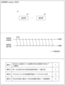
- FIG. 5 is an explanatory diagram for explaining an example in which the system 18 controls the RAN. As shown in FIG. 5, the system 18 includes a control device 500 and a plurality of base stations 80.
- the control device 500 may execute various functions by executing xApp 550. For example, the control device 500 predicts the state of the RAN at a predicted timing after the transmission time from the generation start timing at which generation of a control message for controlling the base station 80 begins to the transmission time for data to reach the base station 80 from the control device 500, and generates a control message based on the predicted state of the RAN. The control device 500 transmits the generated control message to the base station 80.
- the base station 80 receives a control message from the control device 500.
- the base station 80 controls itself according to the received control message.
- control device 500 executes xApp 550 to generate control messages at time intervals of approximately 1 ms and transmits the generated control messages to the base station 80.
- the base station 80 controls itself according to the control messages received from the control device 500.
- control device 500 controls the RAN by having each base station 80 located within the RAN control itself in accordance with a control message. Therefore, since the control device 500, which is an element separate from the RAN, can control the RAN, system 18 satisfies requirement 1.
- control device 500 which is a central element, controls the RAN by having each of the base stations 80, which are distributed elements, control themselves in accordance with control messages. Therefore, since the control device 500, which is a single entity, can control the entire RAN, system 18 satisfies requirement 2.
- control device 500 controls the RAN by transmitting to each base station 80 a control message that can be generated at time intervals of approximately 1 ms, thereby causing each base station 80 to control itself. Therefore, since the control device 500 can generate a control message for each base station 80 at time intervals of approximately 1 ms, system 18 satisfies requirement 3.
- the control device 500 controls the RAN by having each base station 80 control itself according to a control message generated based on the result of predicting the state of the RAN at the predicted timing.
- the state of the RAN at the predicted timing predicted by the control device 500 may differ from the actual state of the RAN at the reception timing when the base station 80 receives the control message from the control device 500. This means that there is a possibility that the control message does not match the actual state of the RAN at the reception timing. However, each base station 80 cannot determine whether the control message received from the control device 500 matches the actual state of the RAN at the reception timing.
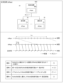
- FIG. 6 is an explanatory diagram for explaining an example of a case where the system 10 controls the RAN.
- the configuration of the system 10 has been described above in the explanation of FIG. 1, so it will not be described here.
- the control device 100 may execute various functions by executing xApp150. For example, the control device 100 predicts the state of the RAN at a predicted timing after the transmission time from the generation start timing at which generation of a control message for controlling the base station 40 begins to the transmission time for data to reach the base station 40 from the control device 100, and generates a control message based on the predicted state of the RAN at the predicted timing. The control device 100 transmits the generated control message to the base station 40.
- the timing may have a time range before and after the reference time.
- the generation start timing may have a time range before and after the generation start time at which the control device 100 actually starts generating the control message.
- the base station 40 may execute various functions by executing dApp45.
- the base station 40 receives a control message from the control device 100, for example.
- the base station 40 acquires the actual state of the RAN at the time when the control message is received from the control device 100.
- the base station 40 executes processing related to the control of the base station itself based on the received control message and the acquired actual state of the RAN.
- the dApp45 may be an example of a control unit.
- the base station 40 judges whether the control message matches the actual state of the RAN at the time of reception. The base station 40 may then control its own device according to the judgment result. For example, if the control message matches the actual state of the RAN at the time of reception, the base station 40 controls its own device according to the control message received from the control device 100. On the other hand, if the control message does not match the actual state of the RAN at the time of reception, the base station 40 may determine the control content of its own device so that it matches the actual state of the RAN at the time of reception, and control its own device according to the determined control content. Also, if the control message does not match the actual state of the RAN at the time of reception, the base station 40 may modify the control message so that it matches the actual state of the RAN at the time of reception, and control its own device according to the modified control message.
- the control device 100 executes xApp150 to generate control messages at time intervals of approximately 1 ms, and transmits the generated control messages to the base station 40.
- the base station 40 executes dApp45 to determine whether the control message received from the control device 100 matches the actual state of the RAN at the time of reception, and controls itself according to the result of the determination.
- the control device 100 controls the RAN by having each base station 40 located within the RAN control itself based on a control message. Therefore, the control device 100, which is an element separate from the RAN, can control the RAN, so the system 10 according to this embodiment satisfies requirement 1.
- the control device 100 which is the central element, controls the RAN by having each of the base stations 40, which are distributed elements, control their own devices based on control messages. Therefore, the control device 100, which is a single entity, can control the entire RAN, so the system 10 of this embodiment satisfies requirement 2.
- the control device 100 controls the RAN by transmitting to each base station 40 a control message that can be generated at time intervals of approximately 1 ms, thereby causing each base station 40 to control itself. Therefore, since the control device 100 can generate a control message for each base station 40 at time intervals of approximately 1 ms, the system 10 of this embodiment satisfies requirement 3.
- each base station 40 judges whether or not the control message received from the control device 100 matches the actual state of the RAN at the time of reception, and controls itself according to the judgment result. As a result, even if the control message does not match the actual state of the RAN at the time of reception, each base station 40 can control itself to match the actual state of the RAN at the time of reception by determining the control content of its own device or by modifying the control message. Therefore, the system 10 of this embodiment satisfies requirement 4.
- the system 10 according to this embodiment satisfies all of requirements 1 to 4 simultaneously. Therefore, the system 10 according to this embodiment can achieve high-performance RAN control.
- FIG. 6 for a table summarizing whether the system 10 according to this embodiment satisfies each of requirements 1 to 4.
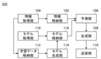
- FIG. 7 shows an example of a schematic functional configuration of the control device 100.
- the control device 100 may include an information storage unit 102, an information acquisition unit 104, a prediction unit 106, a generation unit 108, a transmission unit 110, a learning data storage unit 112, a model generation unit 114, a model storage unit 116, and a model acquisition unit 118. Note that it is not essential for the control device 100 to include all of these components.
- the information storage unit 102 stores various types of information.
- the information storage unit 102 stores, for example, base station information indicating a plurality of base stations 40 arranged within the RAN.
- the base station information includes, for example, installation location information indicating the installation location of the base station 40.
- the base station information includes performance information indicating the performance of the base station 40.
- the base station information may include any other information related to the base station 40.
- the information acquisition unit 104 acquires various information. For example, the information acquisition unit 104 acquires various information by receiving various information from an external device such as the base station 40. The information acquisition unit 104 acquires various information by accepting input from a user of the control device 100 at an input unit that the control device 100 has. The user of the control device 100 is, for example, a RAN administrator. The information acquisition unit 104 may store the acquired various information in the information storage unit 102.
- the information acquisition unit 104 acquires the status of the RAN.
- the information acquisition unit 104 may store the acquired status of the RAN in the information storage unit 102 as RAN status information.
- the state of the RAN includes, for example, the state of at least one base station 40 located within the RAN.
- the state of the RAN includes, for example, the states of all base stations 40 located within the RAN.
- the state of the base station 40 includes, for example, the state of radio resources allocated by the base station 40 to the communication terminal 200.
- the radio resources are allocated to the communication terminal 200, for example, in resource block units.
- the state of the base station 40 includes, for example, the state of the channel formed between the base station 40 and the communication terminal 200.
- the state of the channel includes, for example, the state of the amount of attenuation that the signal undergoes when the signal is transmitted between the base station 40 and the communication terminal 200 via the channel.
- the state of the channel may also include the state of the amount of phase rotation that the signal undergoes when the signal is transmitted between the base station 40 and the communication terminal 200 via the channel.
- the state of the base station 40 includes, for example, the state of the traffic volume of the communication between the base station 40 and the communication terminal 200.
- the state of the traffic volume of the communication between the base station 40 and the communication terminal 200 includes, for example, the state of the total traffic volume, which is the sum of the traffic volumes of each communication between the base station 40 and each of the multiple communication terminals 200.
- the state of the traffic volume of the communication between the base station 40 and the communication terminal 200 may include the state of the average traffic volume, which is the average of the traffic volumes of each communication between the base station 40 and each of the multiple communication terminals 200.
- the state of the base station 40 includes, for example, the state of the beam output by the antenna mounted on the base station 40.
- the state of the beam includes, for example, the state of the output power of the beam.
- the state of the beam includes, for example, the state of the output direction of the beam.
- the state of the beam includes, for example, the state of the frequency of the beam.
- the state of the beam may also include the state of the phase of the beam.
- the state of the base station 40 may include the state of the processing load of the base station 40.
- the state of the processing load of the base station 40 may include, for example, the utilization state of a processor installed in the base station 40.
- the state of the processing load of the base station 40 may include, for example, the utilization state of a memory installed in the base station 40.
- the state of the processing load of the base station 40 may include the utilization state of any other components used to control various functions of the base station 40.
- the state of the RAN includes, for example, the state of the communication terminal 200.
- the state of the communication terminal 200 includes, for example, the state of QoS (Quality of Service) requested by the communication terminal 200.
- the state of the communication terminal 200 includes, for example, the state of the delay tolerated by the communication terminal 200.
- the state of the communication terminal 200 includes the state of the jitter tolerated by the communication terminal 200.
- the state of the communication terminal 200 may include the state of the packet loss rate tolerated by the communication terminal 200.
- the RAN status may include weather conditions in a predetermined area including the installation location of the base station 40 located within the RAN.
- the RAN status may also include the state of people flow in the area.
- the prediction unit 106 predicts the state of the RAN in which multiple base stations 40 are located.
- the prediction unit 106 predicts, for example, the state of the RAN at the prediction timing.
- the prediction unit 106 for example, periodically predicts the state of the RAN.
- the prediction unit 106 predicts the state of the RAN at a time interval of, for example, 1 ms.
- the prediction unit 106 may predict the state of the RAN at any other time interval.
- the prediction unit 106 predicts the state of the RAN, for example, based on the RAN state information stored in the information storage unit 102.
- the prediction unit 106 predicts the state of the RAN, for example, based on RAN state information in which the elapsed time until the generation start timing is shorter than a predetermined elapsed time.
- the predetermined elapsed time is, for example, 10 s.
- the prediction unit 106 predicts the state of the RAN, for example, by predicting the state of the traffic volume of communication between the base station 40 and the communication terminal 200.
- the prediction unit 106 predicts the state of the traffic volume, for example, by predicting the transition of the traffic volume based on the traffic volume whose elapsed time until the start timing is shorter than a predetermined time.
- the prediction unit 106 predicts the state of the RAN, for example, by predicting the state of the channel for the channel formed between the base station 40 and the communication terminal 200.
- the prediction unit 106 predicts the state of the channel, for example, by performing channel estimation.
- the prediction unit 106 predicts the state of the RAN, for example, by predicting the state of the beam output by an antenna mounted on the base station 40.
- the prediction unit 106 predicts the state of the beam, for example, by predicting the propagation characteristics of radio waves within the wireless communication area formed by the base station 40.
- the prediction unit 106 may predict the state of the RAN by predicting the state of the processing load of the base station 40. For example, the prediction unit 106 predicts the state of the processing load of the base station 40 by predicting the transition of the processing load of the base station 40 based on the processing load of the base station 40 whose elapsed time until the start timing is shorter than a predetermined time.
- the generating unit 108 generates information for controlling the base station 40 to be controlled.
- the generating unit 108 generates, for example, a control message.
- the generating unit 108 generates the control message based on, for example, the state of the RAN at the prediction timing predicted by the predicting unit 106.
- the generating unit 108 may generate the control message based on the state of the RAN at the acquisition timing at which the information acquiring unit 104 acquires the state of the RAN.
- the control message includes, for example, radio resource information indicating radio resources to be allocated to the communication terminal 200.
- the radio resource information includes, for example, resource blocks indicating resource blocks to be allocated to the communication terminal 200.
- the control message includes, for example, antenna control information to control an antenna mounted in the base station 40.
- the antenna control information includes, for example, output power control information to control the output power of a beam output by the antenna.
- the antenna control information includes, for example, output direction control information to control the output direction of a beam output by the antenna.
- the antenna control information includes, for example, frequency control information to control the frequency state of the beam output by the antenna.
- the antenna control information may include phase control information to control the phase of the beam output by the antenna.
- the control message may include a prediction result obtained by the prediction unit 106 predicting the state of the RAN.
- the generating unit 108 generates a control message, for example, to guarantee the QoS required by the communication terminal 200.
- the generating unit 108 generates a control message, for example, to maximize the spectral efficiency, which is the total amount of data that can be transmitted in the bandwidth allocated to the RAN.
- the generating unit 108 may generate a control message to cause the base station 40 to perform beamforming using an antenna mounted on the base station 40.
- the generating unit 108 may have a function for generating a policy.
- the generating unit 108 may generate the policy in the same manner as when the control device 300 or the control device 400 generates the policy.
- the transmitter 110 transmits the control message generated by the generator 108 to the base station 40 to be controlled.
- the transmitter 110 transmits the control message to the base station 40, for example, via the core network 20.
- the transmitter 110 transmits the control message to the base station 40, for example, via the E2 interface defined by the O-RAN Alliance.
- the learning data storage unit 112 stores learning data.
- the learning data includes, for example, RAN status information acquired by the information acquisition unit 104 at a reference timing, and multiple pieces of RAN status information acquired by the information acquisition unit 104 in which the elapsed time until the reference timing is shorter than a predetermined elapsed time.
- the model generation unit 114 generates an estimation model by machine learning that estimates the state of the RAN at the prediction timing. For example, the model generation unit 114 uses multiple pieces of learning data stored in the learning data storage unit 112 as teacher data to generate an estimation model by machine learning that estimates the state of the RAN at the prediction timing from multiple pieces of RAN state information acquired by the information acquisition unit 104, in which the elapsed period until the prediction timing is shorter than a predetermined elapsed time. The model generation unit 114 may store the generated estimation model in the model storage unit 116.
- the model acquisition unit 118 acquires an estimation model that estimates the state of the RAN at the prediction timing.
- the model acquisition unit 118 acquires, for example, a model similar to the estimation model generated by the model generation unit 114.
- the model acquisition unit 118 may store the acquired estimation model in the model storage unit 116.
- the prediction unit 106 may predict the state of the RAN using an estimation model stored in the model storage unit 116. For example, the prediction unit 106 uses the estimation model to predict the state of the RAN at the prediction timing from multiple pieces of RAN state information acquired by the information acquisition unit 104, in which the elapsed period until the prediction timing is shorter than a predetermined elapsed time.
- FIG. 8 shows an example of a schematic functional configuration of the control unit 42.
- the control unit 42 is mounted on one of the base stations 40 arranged in the RAN, and controls the one base station 40.
- the control unit 42 may be implemented as hardware such as a CPU, or as software such as a dApp 45.
- the control unit 42 may include a receiving unit 44, an acquiring unit 46, and a processing unit 48. Note that it is not essential that the control unit 42 includes all of these components.
- the receiver 44 receives various types of information. For example, the receiver 44 receives a control message from the control device 100 to control a base station 40 equipped with a control unit 42. For example, the receiver 44 receives a control message from the control device 100 via the core network 20. For example, the receiver 44 receives a control message from the control device 100 via the E2 interface.
- the acquisition unit 46 acquires the state of the RAN. For example, the acquisition unit 46 acquires the state of the RAN at the reception timing.
- the acquisition unit 46 acquires the RAN status, for example, by acquiring the status of one base station 40 equipped with the control unit 42.
- the acquisition unit 46 may acquire the RAN status by further acquiring the status of another base station 40 different from the one base station 40 among the multiple base stations 40 arranged in the RAN.
- the acquisition unit 46 acquires the RAN status of the other base station 40, for example, by receiving RAN status information of the other base station 40 from the other base station 40.
- the acquisition unit 46 may acquire the RAN status of the other base station 40 by receiving RAN status information of the other base station 40 from the control device 100.
- the processing unit 48 executes processing related to the control of a base station 40 that is equipped with the control unit 42.
- the processing unit 48 executes processing related to the control of the base station 40, for example, based on the control message received by the receiving unit 44 and the state of the RAN acquired by the acquiring unit 46 at the time of reception.
- the processing unit 48 determines whether the control message is compatible with the state of the RAN acquired by the acquisition unit 46 at the time of reception.
- the processing unit 48 determines whether the process of allocating the radio resources indicated by the radio resource information included in the control message to the communication terminal 200 is compatible with the state of the RAN acquired by the acquisition unit 46 at the time of reception, thereby determining whether the control message is compatible with the state of the RAN acquired by the acquisition unit 46 at the time of reception.
- the processing unit 48 determines whether the process of beamforming using an antenna mounted on the one base station 40 according to the antenna control information included in the control message is compatible with the state of the RAN acquired by the acquisition unit 46 at the time of reception, thereby determining whether the control message is compatible with the state of the RAN acquired by the acquisition unit 46 at the time of reception.
- the processing unit 48 may determine whether the control message conforms to the state of the RAN acquired by the acquisition unit 46 at the reception timing by comparing the state of the RAN predicted by the control device 100 at the prediction timing indicated by the prediction result included in the control message with the state of the RAN acquired by the acquisition unit 46 at the reception timing. For example, if the total traffic volume error between the total traffic volume predicted by the control device 100 at the prediction timing and the total traffic volume acquired by the acquisition unit 46 at the reception timing is smaller than a predetermined total traffic volume error threshold, the processing unit 48 determines that the control message conforms to the state of the RAN acquired by the acquisition unit 46 at the reception timing.
- the processing unit 48 determines that the control message does not conform to the state of the RAN acquired by the acquisition unit 46 at the reception timing. For example, if the average traffic volume error between the average traffic volume predicted by the control device 100 at the prediction timing and the average traffic volume acquired by the acquisition unit 46 at the reception timing is smaller than a predetermined average traffic volume error threshold, the processing unit 48 determines that the control message is compatible with the state of the RAN acquired by the acquisition unit 46 at the reception timing. On the other hand, if the average traffic volume error is larger than the average traffic volume error threshold, the processing unit 48 determines that the control message is not compatible with the state of the RAN acquired by the acquisition unit 46 at the reception timing.
- the processing unit 48 determines that the control message is compatible with the state of the RAN acquired by the acquisition unit 46 at the reception timing.
- the processing unit 48 determines that the control message is not compatible with the state of the RAN acquired by the acquisition unit 46 at the reception timing.
- the processing unit 48 determines that the control message is compatible with the state of the RAN acquired by the acquisition unit 46 at the reception timing. On the other hand, if the memory usage error is greater than the memory usage error threshold, the processing unit 48 determines that the control message does not match the RAN state acquired by the acquisition unit 46 at the time of reception.
- the processing unit 48 determines whether the control message conforms to the RAN state acquired by the acquisition unit 46 at the time of reception by determining whether a malfunction will occur in the RAN function when, for example, processing is performed to control the one base station 40 in accordance with the control message in the RAN state acquired by the acquisition unit 46 at the time of reception. In this case, the processing unit 48 may determine that the control message conforms to the RAN state acquired by the acquisition unit 46 at the time of reception if it determines that no malfunction will occur in the RAN function, and may determine that the control message does not conform to the RAN state acquired by the acquisition unit 46 at the time of reception if it determines that a malfunction will occur in the RAN function.
- the processing unit 48 determines that a malfunction will occur in the RAN function when it is determined that a communication terminal 200 whose QoS cannot be guaranteed will occur if the base station 40 is controlled according to the control message.
- the processing unit 48 determines that a malfunction will occur in the RAN function when it is determined that the spectral efficiency of the RAN will fall below an allowable lower limit if the base station 40 is controlled according to the control message.
- the processing unit 48 determines that a malfunction will occur in the RAN function when it is determined that congestion will occur in the RAN if the base station 40 is controlled according to the control message.
- the processing unit 48 determines that a malfunction will occur in the RAN function when it is determined that interference will occur between a beam output by an antenna mounted on the base station 40 and another beam if the base station 40 is controlled according to the control message.
- the processing unit 48 determines that a malfunction will occur in the RAN function when it is determined that interference will occur between a beam output by an antenna mounted on the base station 40 and another beam if the base station 40 is controlled according to the control message.
- the processing unit 48 determines that a malfunction will occur in the RAN function when it is determined that the processing load of the base station 40 will exceed an upper limit if the base station 40 is controlled according to the control message.
- the processing unit 48 may determine that a malfunction will occur in the RAN function when it is determined that the control of the one base station 40 in accordance with the control message will cause the RAN function to fail.
- the processing unit 48 determines that the RAN function will fail, for example, when it is determined that the control of the one base station 40 in accordance with the control message will cause wireless communication connections between more than a predetermined number of communication terminals 200 and the one base station 40 to be disconnected.
- the processing unit 48 determines that the RAN function will fail, for example, when it is determined that the control of the one base station 40 in accordance with the control message will cause the proportion of communication terminals 200 whose wireless communication connections with the one base station 40 are disconnected to the total number of communication terminals 200 in the wireless communication area formed by the one base station 40 to be higher than a predetermined proportion.
- the processing unit 48 determines that the RAN function will fail when, for example, controlling the base station 40 according to the control message will result in a processing task with a processing volume that exceeds the processing capacity of the base station 40, and as a result, the processing delay that occurs when the base station 40 processes the processing task will be longer than a predetermined allowable processing delay.
- the processing unit 48 may also determine that the RAN function will fail when it determines that controlling the base station 40 according to the control message will cause thermal runaway of components such as a processor and memory mounted on the base station 40.
- the processing unit 48 determines that the control message matches the state of the RAN acquired by the acquisition unit 46 at the time of reception, the processing unit 48 controls the base station 40 in accordance with the control message. On the other hand, if the processing unit 48 determines that the control message does not match the state of the RAN acquired by the acquisition unit 46 at the time of reception, the processing unit 48 refuses to control the base station 40 in accordance with the control message.
- the processing unit 48 determines the control content of the base station 40 so as to conform to the state of the RAN acquired by the acquisition unit 46 at the time of reception, and controls the base station 40 in accordance with the determined control content. In this case, the processing unit 48 may discard the control message.
- the processing unit 48 determines the control contents of the base station 40, for example, so that malfunctions do not occur in the functions of the RAN.
- the processing unit 48 determines the control contents of the base station 40, for example, so that a communication terminal 200 for which QoS cannot be guaranteed does not occur.
- the processing unit 48 determines the control contents of the base station 40, for example, so that the spectral efficiency of the RAN does not fall below an allowable lower limit.
- the processing unit 48 determines the control contents of the base station 40, for example, so that congestion does not occur within the RAN.
- the processing unit 48 determines the control contents of the base station 40, for example, so that interference does not occur between the beam output by the antenna mounted on the base station 40 and other beams.
- the processing unit 48 may determine the control contents of the base station 40, for example, so that the processing load of the base station 40 does not exceed an upper limit.
- the processing unit 48 may determine the control contents of the base station 40 so that the function of the RAN does not fail.
- the processing unit 48 determines the control contents of the base station 40 so that, for example, the wireless communication connection between the communication terminals 200 and the base station 40 is not cut off more than a predetermined number of times.
- the processing unit 48 determines the control contents of the base station 40 so that, for example, the ratio of the communication terminals 200 whose wireless communication connection with the base station 40 is cut off to the total number of communication terminals 200 in the wireless communication area formed by the base station 40 is not higher than a predetermined ratio.
- the processing unit 48 determines the control contents of the base station 40 so that, for example, the amount of processing work by the base station 40 does not exceed the processing capacity of the base station 40.
- the processing unit 48 may offload the processing work that is not processed by the base station 40 to another base station 40 arranged in the RAN.
- the processing unit 48 may determine the control content of the base station 40 so that components such as a processor and memory mounted on the base station 40 do not experience thermal runaway.
- the processing unit 48 may modify the control message so that it conforms to the state of the RAN acquired by the acquisition unit 46 at the time of reception. In this case, the processing unit 48 may control the one base station 40 in accordance with the modified control message.
- the processing unit 48 modifies the control message so that malfunctions do not occur in the functions of the RAN.
- the processing unit 48 modifies the control message so that communication terminals 200 for which QoS cannot be guaranteed do not occur.
- the processing unit 48 modifies the control message so that the spectral efficiency of the RAN does not fall below an allowable lower limit.
- the processing unit 48 modifies the control message so that congestion does not occur within the RAN.
- the processing unit 48 modifies the control message so that interference does not occur between the beam output by the antenna mounted on the one base station 40 and other beams.
- the processing unit 48 may also modify the control message so that the processing load of the one base station 40 does not exceed an upper limit.
- the processing unit 48 may modify the control message so that the function of the RAN does not fail. For example, the processing unit 48 modifies the control message so that the wireless communication connection between the communication terminals 200 and the one base station 40 is not cut off more than a predetermined number. For example, the processing unit 48 modifies the control message so that the ratio of the communication terminals 200 whose wireless communication connection with the one base station 40 is cut off to the total number of communication terminals 200 in the wireless communication area formed by the one base station 40 is not higher than a predetermined ratio. For example, the processing unit 48 modifies the control message so that the amount of processing work by the one base station 40 does not exceed the processing capacity of the one base station 40.
- the processing unit 48 may offload the processing work that is not processed by the one base station 40 to another base station 40 arranged in the RAN.
- the processing unit 48 may modify the control message so that the components such as the processor and memory mounted on the one base station 40 do not thermally run away.
- the processing unit 48 may not control the base station 40, provided that no malfunction occurs in the RAN functionality. If the processing unit 48 refuses to control the base station 40 in accordance with the control message, the processing unit 48 may not control the base station 40, provided that no malfunction occurs in the RAN functionality.
- FIG. 9 is an explanatory diagram for explaining an example of the processing flow of the system 10.
- a state in which the control device 100 has not predicted the state of the RAN is explained as the starting state.
- step (sometimes abbreviated to S) 102 the prediction unit 106 predicts the state of the RAN at the predicted timing.
- the generation unit 108 generates a control message based on the state of the RAN predicted by the prediction unit 106 in S102.
- the transmission unit 110 transmits the control message generated by the generation unit 108 in S104 to the base station 40 equipped with the control unit 42 via the E2 interface.
- the acquisition unit 46 acquires the state of the RAN at the reception timing when the receiver 44 received the control message from the control device 100 through the E2 interface in S106.
- the processing unit 48 executes a determination process to determine whether or not the control message matches the state of the RAN acquired by the acquisition unit 46 in S108, based on the control message received by the receiver 44 in S106 and the state of the RAN acquired by the acquisition unit 46 in S108.
- the processing unit 48 executes a control process to control the base station 40 equipped with the control unit 42, based on the determination result of the determination process in S110.
- FIG. 10 shows a schematic diagram of an example of a hardware configuration of a computer 1200 functioning as the control device 100 or the control unit 42.
- a program installed on the computer 1200 can cause the computer 1200 to function as one or more "parts" of the device according to the above embodiment, or to execute operations or one or more "parts” associated with the device according to the above embodiment, and/or to execute a process or steps of the process according to the above embodiment.
- Such a program can be executed by the CPU 1212 to cause the computer 1200 to execute specific operations associated with some or all of the blocks of the flowcharts and block diagrams described herein.
- the computer 1200 includes a CPU 1212, a RAM 1214, and a graphics controller 1216, which are connected to each other by a host controller 1210.
- the computer 1200 also includes input/output units such as a communication interface 1222, a storage device 1224, a DVD drive 1226, and an IC card drive, which are connected to the host controller 1210 via an input/output controller 1220.
- the DVD drive 1226 may be a DVD-ROM drive, a DVD-RAM drive, or the like.
- the storage device 1224 may be a hard disk drive, a solid state drive, or the like.
- the computer 1200 also includes legacy input/output units such as a ROM 1230 and a keyboard 1242, which are connected to the input/output controller 1220 via an input/output chip 1240.
- the CPU 1212 operates according to the programs stored in the ROM 1230 and the RAM 1214, thereby controlling each unit.
- the graphics controller 1216 acquires image data generated by the CPU 1212 into a frame buffer or the like provided in the RAM 1214 or into itself, and causes the image data to be displayed on the display device 1218.
- the communication interface 1222 communicates with other electronic devices via a network.
- the storage device 1224 stores programs and data used by the CPU 1212 in the computer 1200.
- the DVD drive 1226 reads programs or data from a DVD-ROM 1227 or the like, and provides the programs or data to the storage device 1224.
- the IC card drive reads programs and data from an IC card and/or writes programs and data to an IC card.
- ROM 1230 stores therein a boot program or the like to be executed by computer 1200 upon activation, and/or a program that depends on the hardware of computer 1200.
- I/O chip 1240 may also connect various I/O units to I/O controller 1220 via USB ports, parallel ports, serial ports, keyboard ports, mouse ports, etc.
- the programs are provided by a computer-readable storage medium such as a DVD-ROM 1227 or an IC card.
- the programs are read from the computer-readable storage medium, installed in the storage device 1224, RAM 1214, or ROM 1230, which are also examples of computer-readable storage media, and executed by the CPU 1212.
- the information processing described in these programs is read by the computer 1200, and brings about cooperation between the programs and the various types of hardware resources described above.
- An apparatus or method may be configured by realizing the operation or processing of information according to the use of the computer 1200.
- CPU 1212 may execute a communication program loaded into RAM 1214 and instruct communication interface 1222 to perform communication processing based on the processing described in the communication program.
- communication interface 1222 reads transmission data stored in a transmission buffer area provided in RAM 1214, storage device 1224, DVD-ROM 1227, or a recording medium such as an IC card, and transmits the read transmission data to the network, or writes received data received from the network to a reception buffer area or the like provided on the recording medium.
- the CPU 1212 may also cause all or a necessary portion of a file or database stored in an external recording medium such as the storage device 1224, DVD drive 1226 (DVD-ROM 1227), IC card, etc. to be read into the RAM 1214, and perform various types of processing on the data on the RAM 1214. The CPU 1212 may then write back the processed data to the external recording medium.
- an external recording medium such as the storage device 1224, DVD drive 1226 (DVD-ROM 1227), IC card, etc.
- CPU 1212 may perform various types of processing on data read from RAM 1214, including various types of operations, information processing, conditional judgment, conditional branching, unconditional branching, information search/replacement, etc., as described throughout this disclosure and specified by the instruction sequence of the program, and write back the results to RAM 1214.
- CPU 1212 may also search for information in a file, database, etc. in the recording medium.
- CPU 1212 may search for an entry whose attribute value of the first attribute matches a specified condition from among the multiple entries, read the attribute value of the second attribute stored in the entry, and thereby obtain the attribute value of the second attribute associated with the first attribute that satisfies a predetermined condition.
- the above-described programs or software modules may be stored in a computer-readable storage medium on the computer 1200 or in the vicinity of the computer 1200.
- a recording medium such as a hard disk or RAM provided in a server system connected to a dedicated communication network or the Internet can be used as a computer-readable storage medium, thereby providing the programs to the computer 1200 via the network.
- the blocks in the flowcharts and block diagrams in this embodiment may represent stages of a process in which an operation is performed or "parts" of a device responsible for performing the operation. Particular stages and “parts" may be implemented by dedicated circuitry, programmable circuitry provided with computer-readable instructions stored on a computer-readable storage medium, and/or a processor provided with computer-readable instructions stored on a computer-readable storage medium.
- the dedicated circuitry may include digital and/or analog hardware circuitry and may include integrated circuits (ICs) and/or discrete circuits.
- the programmable circuitry may include reconfigurable hardware circuitry including AND, OR, XOR, NAND, NOR, and other logical operations, flip-flops, registers, and memory elements, such as, for example, field programmable gate arrays (FPGAs) and programmable logic arrays (PLAs).
- FPGAs field programmable gate arrays
- PDAs programmable logic arrays
- a computer-readable storage medium may include any tangible device capable of storing instructions that are executed by a suitable device, such that a computer-readable storage medium having instructions stored thereon comprises an article of manufacture that includes instructions that can be executed to create means for performing the operations specified in the flowchart or block diagram.
- Examples of computer-readable storage media may include electronic storage media, magnetic storage media, optical storage media, electromagnetic storage media, semiconductor storage media, and the like.
- Computer-readable storage media may include floppy disks, diskettes, hard disks, random access memories (RAMs), read-only memories (ROMs), erasable programmable read-only memories (EPROMs or flash memories), electrically erasable programmable read-only memories (EEPROMs), static random access memories (SRAMs), compact disk read-only memories (CD-ROMs), digital versatile disks (DVDs), Blu-ray disks, memory sticks, integrated circuit cards, and the like.
- RAMs random access memories
- ROMs read-only memories
- EPROMs or flash memories erasable programmable read-only memories
- EEPROMs electrically erasable programmable read-only memories
- SRAMs static random access memories
- CD-ROMs compact disk read-only memories
- DVDs digital versatile disks
- Blu-ray disks memory sticks, integrated circuit cards, and the like.
- the computer readable instructions may include either assembler instructions, instruction set architecture (ISA) instructions, machine instructions, machine-dependent instructions, microcode, firmware instructions, state setting data, or source or object code written in any combination of one or more programming languages, including object-oriented programming languages such as Smalltalk (registered trademark), JAVA (registered trademark), C++, etc., and conventional procedural programming languages such as the "C" programming language or similar programming languages.
- ISA instruction set architecture
- machine instructions machine-dependent instructions
- microcode firmware instructions
- state setting data or source or object code written in any combination of one or more programming languages, including object-oriented programming languages such as Smalltalk (registered trademark), JAVA (registered trademark), C++, etc., and conventional procedural programming languages such as the "C" programming language or similar programming languages.
- the computer-readable instructions may be provided to a processor of a general-purpose computer, special-purpose computer, or other programmable data processing apparatus, or to a programmable circuit, either locally or over a local area network (LAN), a wide area network (WAN) such as the Internet, so that the processor of the general-purpose computer, special-purpose computer, or other programmable data processing apparatus, or to a programmable circuit, executes the computer-readable instructions to generate means for performing the operations specified in the flowcharts or block diagrams.
- processors include computer processors, processing units, microprocessors, digital signal processors, controllers, microcontrollers, etc.
Landscapes
- Engineering & Computer Science (AREA)
- Computer Networks & Wireless Communication (AREA)
- Signal Processing (AREA)
- Quality & Reliability (AREA)
- Mobile Radio Communication Systems (AREA)
Abstract
Description
[先行技術文献]
[特許文献]
[特許文献1]特開2022-165659号公報
Claims (12)
- RAN(Radio Access Network)内に配置されている複数の基地局を制御する制御装置と、
前記複数の基地局のうちの一の基地局に搭載され、且つ、前記一の基地局を制御する制御ユニットと
を備え、
前記制御装置は、
前記一の基地局を制御する制御メッセージの生成を開始する生成開始タイミングから、データが前記制御装置から前記一の基地局に到達するまでの伝送時間が経過した後の予測タイミングにおける、前記RANの状態を予測する予測部と、
前記予測部によって予測された前記RANの前記状態に基づいて、前記制御メッセージを生成する生成部と、
前記一の基地局に前記制御メッセージを送信する送信部と
を有し、
前記制御ユニットは、
前記制御装置から前記制御メッセージを受信する受信部と、
前記受信部が前記制御メッセージを受信した受信タイミングにおける前記RANの状態を取得する取得部と、
前記制御メッセージと、前記取得部によって取得された前記RANの前記状態とに基づいて、前記一の基地局の制御に関連する処理を実行する処理部と
を有する、制御システム。 - 前記処理部は、前記制御メッセージが前記取得部によって取得された前記RANの前記状態に適合しているか否かを判定し、前記制御メッセージが前記取得部によって取得された前記RANの前記状態に適合していると判定した場合に、前記制御メッセージに従って前記一の基地局を制御する処理を実行する、請求項1に記載の制御システム。
- 前記処理部は、前記制御メッセージが前記取得部によって取得された前記RANの前記状態に適合していないと判定した場合に、前記取得部によって取得された前記RANの前記状態に適合するように前記一の基地局の制御内容を決定し、決定した制御内容に従って前記一の基地局を制御する処理を実行する、請求項2に記載の制御システム。
- 前記処理部は、前記制御メッセージが前記取得部によって取得された前記RANの前記状態に適合していないと判定した場合に、前記取得部によって取得された前記RANの前記状態に適合するように前記制御メッセージを修正し、修正した前記制御メッセージに従って前記一の基地局を制御する処理を実行する、請求項2に記載の制御システム。
- 前記処理部は、前記取得部によって取得された前記RANの前記状態において前記制御メッセージに従って前記一の基地局を制御する処理を実行した場合に、前記RANの機能に不具合が発生するか否かを判定することによって、前記制御メッセージが前記取得部によって取得された前記RANの前記状態に適合しているか否かを判定する、請求項2から4のいずれか一項に記載の制御システム。
- 前記生成部は、前記予測部が前記RANの前記状態を予測した予測結果を含む前記制御メッセージを生成し、
前記処理部は、前記制御メッセージに含まれる前記予測結果によって示される前記RANの前記状態と、前記取得部によって取得された前記RANの前記状態とを照合することによって、前記制御メッセージが前記取得部によって取得された前記RANの前記状態に適合しているか否かを判定する、請求項2から4のいずれか一項に記載の制御システム。 - 前記生成部は、前記一の基地局によって形成されている無線通信エリア内の通信端末に割り当てられる無線リソースを示す無線リソース情報を含む前記制御メッセージを生成し、
前記処理部は、前記制御メッセージに含まれる前記無線リソース情報によって示される前記無線リソースを前記通信端末に割り当てる処理が前記取得部によって取得された前記RANの前記状態に適合しているか否かを判定することによって、前記制御メッセージが前記取得部によって取得された前記RANの前記状態に適合しているか否かを判定する、請求項2から4のいずれか一項に記載の制御システム。 - RAN内に配置されている複数の基地局を制御する制御装置であって、
前記複数の基地局のうちの一の基地局を制御する制御メッセージの生成を開始する生成開始タイミングから、データが前記制御装置から前記一の基地局に到達するまでの伝送時間が経過した後の予測タイミングにおける、前記RANの状態を予測する予測部と、
前記予測部によって予測された前記RANの前記状態に基づいて、前記制御メッセージを生成する生成部と、
前記一の基地局に前記制御メッセージを送信する送信部と
を備える、制御装置。 - コンピュータを、請求項8に記載の制御装置として機能させるためのプログラム。
- RAN内に配置されている複数の基地局のうちの一の基地局に搭載され、且つ、前記一の基地局を制御する制御ユニットであって、
前記複数の基地局を制御する制御装置から、前記一の基地局を制御する制御メッセージを受信する受信部であって、前記制御メッセージは、前記制御装置が前記制御メッセージの生成を開始する生成開始タイミングから、データが前記制御装置から前記一の基地局に到達するまでの伝送時間が経過した後の予測タイミングにおける、前記制御装置によって予測された前記RANの状態に基づいて生成される、受信部と、
前記受信部が前記制御メッセージを受信した受信タイミングにおける前記RANの状態を取得する取得部と、
前記制御メッセージと、前記取得部によって取得された前記RANの前記状態とに基づいて、前記一の基地局の制御に関連する処理を実行する処理部と
を備える、制御ユニット。 - 前記処理部は、前記制御メッセージが前記取得部によって取得された前記RANの前記状態に適合しているか否かを判定し、前記制御メッセージが前記取得部によって取得された前記RANの前記状態に適合していると判定した場合に、前記制御メッセージに従って前記一の基地局を制御する処理を実行する、請求項10に記載の制御ユニット。
- コンピュータを、請求項10又は11に記載の制御ユニットとして機能させるためのプログラム。
Priority Applications (4)
| Application Number | Priority Date | Filing Date | Title |
|---|---|---|---|
| EP24823466.8A EP4730911A1 (en) | 2023-06-16 | 2024-06-14 | Control system, control device, control unit, and program |
| CN202480040035.XA CN121336497A (zh) | 2023-06-16 | 2024-06-14 | 控制系统、控制装置、控制单元以及程序 |
| KR1020267001031A KR20260023033A (ko) | 2023-06-16 | 2024-06-14 | 제어 시스템, 제어 유닛, 및 프로그램 |
| US19/417,195 US20260101204A1 (en) | 2023-06-16 | 2025-12-11 | Control system, control unit, and program |
Applications Claiming Priority (2)
| Application Number | Priority Date | Filing Date | Title |
|---|---|---|---|
| JP2023-098844 | 2023-06-16 | ||
| JP2023098844A JP7604561B1 (ja) | 2023-06-16 | 2023-06-16 | 制御システム、制御ユニット、及びプログラム |
Related Child Applications (1)
| Application Number | Title | Priority Date | Filing Date |
|---|---|---|---|
| US19/417,195 Continuation US20260101204A1 (en) | 2023-06-16 | 2025-12-11 | Control system, control unit, and program |
Publications (1)
| Publication Number | Publication Date |
|---|---|
| WO2024257853A1 true WO2024257853A1 (ja) | 2024-12-19 |
Family
ID=93852248
Family Applications (1)
| Application Number | Title | Priority Date | Filing Date |
|---|---|---|---|
| PCT/JP2024/021661 Ceased WO2024257853A1 (ja) | 2023-06-16 | 2024-06-14 | 制御システム、制御装置、制御ユニット、及びプログラム |
Country Status (6)
| Country | Link |
|---|---|
| US (1) | US20260101204A1 (ja) |
| EP (1) | EP4730911A1 (ja) |
| JP (1) | JP7604561B1 (ja) |
| KR (1) | KR20260023033A (ja) |
| CN (1) | CN121336497A (ja) |
| WO (1) | WO2024257853A1 (ja) |
Citations (3)
| Publication number | Priority date | Publication date | Assignee | Title |
|---|---|---|---|---|
| WO2014103434A1 (ja) * | 2012-12-27 | 2014-07-03 | 日本電気株式会社 | 無線パラメータ制御装置、無線パラメータ制御装置システム、無線パラメータ制御方法及びそのプログラム |
| JP2022165659A (ja) | 2021-04-20 | 2022-11-01 | 株式会社Kddi総合研究所 | 基地局機能配置制御装置、基地局機能配置制御方法及びコンピュータプログラム |
| WO2023172292A2 (en) * | 2021-08-25 | 2023-09-14 | Northeastern University | Zero-touch deployment and orchestration of network intelligence in open ran systems |
Family Cites Families (1)
| Publication number | Priority date | Publication date | Assignee | Title |
|---|---|---|---|---|
| JP2015012583A (ja) | 2013-07-02 | 2015-01-19 | 富士通株式会社 | 干渉制御方法、干渉制御装置および無線通信システム |
-
2023
- 2023-06-16 JP JP2023098844A patent/JP7604561B1/ja active Active
-
2024
- 2024-06-14 CN CN202480040035.XA patent/CN121336497A/zh active Pending
- 2024-06-14 EP EP24823466.8A patent/EP4730911A1/en active Pending
- 2024-06-14 KR KR1020267001031A patent/KR20260023033A/ko active Pending
- 2024-06-14 WO PCT/JP2024/021661 patent/WO2024257853A1/ja not_active Ceased
-
2025
- 2025-12-11 US US19/417,195 patent/US20260101204A1/en active Pending
Patent Citations (3)
| Publication number | Priority date | Publication date | Assignee | Title |
|---|---|---|---|---|
| WO2014103434A1 (ja) * | 2012-12-27 | 2014-07-03 | 日本電気株式会社 | 無線パラメータ制御装置、無線パラメータ制御装置システム、無線パラメータ制御方法及びそのプログラム |
| JP2022165659A (ja) | 2021-04-20 | 2022-11-01 | 株式会社Kddi総合研究所 | 基地局機能配置制御装置、基地局機能配置制御方法及びコンピュータプログラム |
| WO2023172292A2 (en) * | 2021-08-25 | 2023-09-14 | Northeastern University | Zero-touch deployment and orchestration of network intelligence in open ran systems |
Non-Patent Citations (2)
| Title |
|---|
| ANONYMOUS: "AI/ML workflow description and requirements", TECHNICAL REPORT, O-RAN.WG2.AIML-V01.03, 1 October 2021 (2021-10-01), pages 1 - 58, XP009546854 * |
| KATSURAGAWA TAICHI, ET AL.: "Making radio access networks more open and intelligent: how to make RAN intelligent", NTT DOCOMO TECHNICAL JOURNAL, vol. 30, no. 1, 30 April 2022 (2022-04-30), pages 27 - 36, XP093247173 * |
Also Published As
| Publication number | Publication date |
|---|---|
| JP7604561B1 (ja) | 2024-12-23 |
| EP4730911A1 (en) | 2026-04-22 |
| US20260101204A1 (en) | 2026-04-09 |
| JP2025000068A (ja) | 2025-01-07 |
| CN121336497A (zh) | 2026-01-13 |
| KR20260023033A (ko) | 2026-02-20 |
Similar Documents
| Publication | Publication Date | Title |
|---|---|---|
| US11704148B2 (en) | Datapath load distribution for a RIC | |
| US20230069604A1 (en) | Use of crds as descriptors for applications, application components, deployments, clouds, ai/ml models, and rte in an o-ran system | |
| CN115119331A (zh) | 用于多接入通信量管理的强化学习 | |
| US11836551B2 (en) | Active and standby RICs | |
| JP2024513628A (ja) | Ric sdk | |
| US12143861B2 (en) | Efficiency of routing traffic to an edge compute server at the far edge of a cellular network | |
| US20190034234A1 (en) | Method For Resource Allocation And Terminal Device | |
| US11392474B2 (en) | Electronic device for controlling interface between a plurality of integrated circuits and operation method thereof | |
| JP2020170888A (ja) | 通信制御装置、通信システム、プログラム、及び通信制御方法 | |
| WO2016209351A1 (en) | Dynamic management of inactivity timer during inter-processor communication | |
| US9594411B2 (en) | Dynamic power management of context aware services | |
| CN118368287A (zh) | 客户端驱动的云网络访问系统和方法 | |
| CN112996067B (zh) | 服务小区确定方法、装置及存储介质 | |
| US11218905B2 (en) | Base station device, program, control device and control method | |
| JP7604561B1 (ja) | 制御システム、制御ユニット、及びプログラム | |
| US12135984B2 (en) | Application management method and apparatus, and device | |
| CN119544797B (zh) | 一种请求处理方法、装置、存储介质及程序产品 | |
| CN112615916A (zh) | 文件部署方法、装置、电子设备以及存储介质 | |
| US12342216B1 (en) | Data transmission method and access point | |
| US20250053461A1 (en) | Method, apparatus, system and computer program for function notification of function accelerator card in cloud system | |
| JP7104192B1 (ja) | 制御装置、プログラム、及び制御方法 | |
| WO2025197809A1 (ja) | 管理基盤、プログラム、情報処理システム、及び管理方法 | |
| CN115278934A (zh) | 通信终端的通信方法和电子装置 | |
| CN120216054A (zh) | 业务运行环境的加载方法、装置、存储介质和电子设备 | |
| JP2021072603A (ja) | 基地局装置、システム、プログラム、飛行体、方法、管理装置、及び管理方法 |
Legal Events
| Date | Code | Title | Description |
|---|---|---|---|
| 121 | Ep: the epo has been informed by wipo that ep was designated in this application |
Ref document number: 24823466 Country of ref document: EP Kind code of ref document: A1 |
|
| ENP | Entry into the national phase |
Ref document number: 1020267001031 Country of ref document: KR Free format text: ST27 STATUS EVENT CODE: A-0-1-A10-A15-NAP-PA0105 (AS PROVIDED BY THE NATIONAL OFFICE) |
|
| WWE | Wipo information: entry into national phase |
Ref document number: 1020267001031 Country of ref document: KR |
|
| WWE | Wipo information: entry into national phase |
Ref document number: 202617003350 Country of ref document: IN |
|
| WWE | Wipo information: entry into national phase |
Ref document number: 2024823466 Country of ref document: EP |
|
| NENP | Non-entry into the national phase |
Ref country code: DE |
|
| ENP | Entry into the national phase |
Ref document number: 2024823466 Country of ref document: EP Effective date: 20260116 |
|
| ENP | Entry into the national phase |
Ref document number: 2024823466 Country of ref document: EP Effective date: 20260116 |
|
| ENP | Entry into the national phase |
Ref document number: 2024823466 Country of ref document: EP Effective date: 20260116 |
|
| WWP | Wipo information: published in national office |
Ref document number: 1020267001031 Country of ref document: KR |
|
| WWP | Wipo information: published in national office |
Ref document number: 2024823466 Country of ref document: EP |