WO2024257626A1 - ヘッドアップディスプレイ装置及び乗り物 - Google Patents
ヘッドアップディスプレイ装置及び乗り物 Download PDFInfo
- Publication number
- WO2024257626A1 WO2024257626A1 PCT/JP2024/019999 JP2024019999W WO2024257626A1 WO 2024257626 A1 WO2024257626 A1 WO 2024257626A1 JP 2024019999 W JP2024019999 W JP 2024019999W WO 2024257626 A1 WO2024257626 A1 WO 2024257626A1
- Authority
- WO
- WIPO (PCT)
- Prior art keywords
- light
- image
- polarized light
- vehicle
- head
- Prior art date
- Legal status (The legal status is an assumption and is not a legal conclusion. Google has not performed a legal analysis and makes no representation as to the accuracy of the status listed.)
- Ceased
Links
Images


Classifications
-
- B—PERFORMING OPERATIONS; TRANSPORTING
- B60—VEHICLES IN GENERAL
- B60K—ARRANGEMENT OR MOUNTING OF PROPULSION UNITS OR OF TRANSMISSIONS IN VEHICLES; ARRANGEMENT OR MOUNTING OF PLURAL DIVERSE PRIME-MOVERS IN VEHICLES; AUXILIARY DRIVES FOR VEHICLES; INSTRUMENTATION OR DASHBOARDS FOR VEHICLES; ARRANGEMENTS IN CONNECTION WITH COOLING, AIR INTAKE, GAS EXHAUST OR FUEL SUPPLY OF PROPULSION UNITS IN VEHICLES
- B60K35/00—Instruments specially adapted for vehicles; Arrangement of instruments in or on vehicles
- B60K35/20—Output arrangements, i.e. from vehicle to user, associated with vehicle functions or specially adapted therefor
- B60K35/21—Output arrangements, i.e. from vehicle to user, associated with vehicle functions or specially adapted therefor using visual output, e.g. blinking lights or matrix displays
- B60K35/23—Head-up displays [HUD]
-
- G—PHYSICS
- G02—OPTICS
- G02B—OPTICAL ELEMENTS, SYSTEMS OR APPARATUS
- G02B27/00—Optical systems or apparatus not provided for by any of the groups G02B1/00 - G02B26/00, G02B30/00
- G02B27/01—Head-up displays
-
- G—PHYSICS
- G09—EDUCATION; CRYPTOGRAPHY; DISPLAY; ADVERTISING; SEALS
- G09F—DISPLAYING; ADVERTISING; SIGNS; LABELS OR NAME-PLATES; SEALS
- G09F9/00—Indicating arrangements for variable information in which the information is built-up on a support by selection or combination of individual elements
Definitions
- the present invention relates to a head-up display device and a vehicle.
- HUD head-up display
- driving information such as vehicle speed and engine RPM
- navigation information onto the windshield or combiner.
- the driver can obtain the information necessary for driving without shifting their gaze to the instrument panel built into the dashboard, known as the instrument panel. This contributes to safer driving.
- Patent document 1 is an example of HUD technology.
- Patent document 1 describes a technology in which light emitted from an LED element is guided to a liquid crystal display (LCOS) via a polarizing beam splitter (PBS).
- the LCOS can change the polarization direction of the light, and the PBS transmits or reflects the light depending on the polarization direction, so an image is generated by turning the pixels on the LCOS on and off.
- the PBS transmits or reflects light depending on the polarization direction, but the light that transmits through the PBS is not used; only the light reflected by the PBS is irradiated onto the LCOS and used to display images, so the efficiency of using the light emitted from the LED element is low.
- the PBS must have a square surface with one side the same length as the effective area for displaying the LCOS image, which makes the PBS larger.
- the present invention aims to provide technology that can improve the efficiency of light utilization.
- one representative head-up display device of the present invention includes an image forming unit that emits image light, an imaging optical system that forms the image generated by the image forming unit as a real image on an intermediate screen, and an image projection unit that reflects the image light of the real image formed by the imaging optical system and projects the reflected image light onto a projection member.
- the image forming unit has a light source that emits light, a display panel that generates an image, and an optical element that separates the light emitted from the light source into multiple optical paths and guides them to the display panel.
- the present invention can improve the efficiency of light utilization.
- FIG. 1 is a schematic diagram showing a configuration example of a vehicle equipped with a head-up display device according to an embodiment of the present invention.
- 1 is a schematic diagram showing an example of installation of a HUD device according to an embodiment of the present invention.
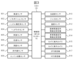
- 2 is a block diagram showing an example of the configuration of sensors and the like for a vehicle information acquisition unit of the HUD device 1 or a vehicle controller to acquire vehicle information.
- FIG. 2 is a block diagram showing a configuration example of functional blocks of the HUD device 1.
- FIG. FIG. 11 is a block diagram showing a modified configuration of the functional blocks of the HUD device 1.
- FIG. 2 illustrates an example of the configuration of a PGU 10 according to the first embodiment.
- FIG. 2 is a plan view of the reflective liquid crystal panel of the first embodiment.
- FIG. 11 is a diagram illustrating an example of the configuration of a PGU 10 according to a second embodiment.
- FIG. 11 is a plan view of a reflective liquid crystal panel according to a second embodiment.
- FIG. 13 is a diagram illustrating an example of the configuration of a PGU 10 according to a third embodiment.
- FIG. 13 is a diagram illustrating an example of the configuration of a PGU 10 according to a fourth embodiment.
- FIG. 13 is a diagram illustrating an example of the configuration of a PGU 10 according to a fifth embodiment.
- FIG. 23 is a diagram illustrating an example of the configuration of a PGU 10 according to a sixth embodiment.
- FIG. 13 is a diagram showing an example of the configuration of a polarization conversion element 140a according to a sixth embodiment.
- FIG. 23 is a diagram illustrating an example of the configuration of a PGU 10 according to a seventh embodiment.
- FIG. 23 is a diagram illustrating an example of the configuration of a PGU 10 according to an eighth
- FIG. 1 is a schematic diagram showing an example of the configuration of a vehicle equipped with a head-up display device according to an embodiment.
- the head-up display (HUD) device 1 in FIG. 1 is mounted on a vehicle 2.
- vehicle 2 is typically an automobile, but is not limited to this and may be a vehicle such as a railroad car in some cases.
- the HUD device 1 acquires vehicle information 4 from various sensors installed in various parts of the vehicle 2, a navigation device, etc.
- the various sensors for example, detect various events that occur in the vehicle 2 and periodically detect the values of various parameters related to the driving conditions.
- the vehicle 2 is equipped with a controller or control unit 8 of the vehicle 2, called, for example, an ECU (Electronic Control Unit).
- the controller 8 controls the driving of the vehicle 2.
- the HUD device 1 communicates with the controller 8 via CAN (Controller Area Network) or LIN (Local Interconnect Network) communication, for example.
- the controller 8 and the HUD device 1 constitute an in-vehicle system of the vehicle 2.
- the HUD device 1 projects image light onto a display area such as the windshield 3 or a combiner based on vehicle information 4, and displays a virtual image.
- the HUD device 1 allows a user such as a driver to visually recognize the image light projected onto the display area 5 of the windshield 3 as a virtual image superimposed on the scenery ahead of the vehicle 2.
- the controller 8 can display video information as a virtual image in the display area 5 by controlling the HUD device 1 via a CAN signal or the like.
- the controller 8 acquires the vehicle information 4 using various sensors, measuring devices, communication devices, etc., as shown in FIG. 3, which will be described later.
- the HUD device 1 inputs and acquires vehicle information 4 and the like from the controller 8 via a CAN signal or the like.
- the HUD device 1 emits image light to the display area 5 based on the vehicle information 4 and the like, and the image light projected onto the display area 5 can be viewed as a virtual image.
- FIG. 1 etc. shows a spatial coordinate system for the vehicle 2.
- the Z axis and Z direction are the vertical direction, in other words, the up-down direction or longitudinal direction of the vehicle.
- the X axis and X direction are the first horizontal direction, in other words, the left-right direction, the width direction or lateral direction of the vehicle.
- the Y axis and Y direction are the second horizontal direction perpendicular to the X axis, in other words, the traveling direction of the vehicle or the front-to-rear direction of the vehicle.
- FIG. 1 is a schematic diagram showing an example of mounting the HUD device 1 of the present embodiment.
- FIG. 2 shows a schematic diagram of the vehicle 2 in FIG. 1 in the Y-Z plane as viewed from the X-axis direction.
- the HUD device 1 is mounted in the dashboard 70 of the vehicle 2.
- the HUD device 1 includes an image forming unit or PGU 10, an imaging optical system 11, a diffuser or intermediate screen 12, and mirrors M2 and M1 within a housing.
- the optical element or mirror M2 included in the HUD device 1 may be arranged in multiple units or may not be arranged at all, and may be a correction lens.
- the optical systems such as the PGU 10, mirror M2, and mirror M1 are arranged and fixed in a predetermined positional relationship within the housing. Also, a part or all of the PGU 10 may be arranged and fixed outside the housing.
- An opening 7 through which the image light of the HUD device 1 is emitted is provided in a part of the housing of the HUD device 1 and in a part of the dashboard 70.
- the opening 7 may be provided with a dust cover made of a transparent material.
- the PGU 10 emits image light that forms an image as linearly polarized or circularly polarized light.
- the image created by the PGU 10 is formed as a real image on a diffuser or intermediate screen 12 by an imaging optical system 11.
- the imaging optical system 11 may be a lens or a mirror.
- the intermediate screen 12 is, for example, a transmissive screen with a Fresnel lens shape on one side and a lenticular lens or a diffusing surface on the other side.
- the diffuser or intermediate screen 12 diffuses the projected light. If the diffuser or intermediate screen 12 disturbs the polarization, differences in brightness will occur in the projected image depending on the location, so it is desirable to use a diffuser 12 with low retardation. On the other hand, in the case of a diffuser with high retardation, it is installed so that the slow axis is perpendicular or parallel to the polarization axis of the image.
- Mirror M2 may be, for example, a flat mirror or a folding mirror.
- mirror M2 is a folding mirror, and reflects the image light diffused by the diffusion plate 12 toward mirror M1.
- Mirror M1 functions as an image projection unit that magnifies and reflects the image light from folding mirror M2 in a direction at a set angle or in a specified direction.
- Mirror M1 is, for example, a free-form mirror or a mirror with an asymmetric shape about the optical axis.
- mirror M1 is a mirror with a concave reflective surface.
- the angle or orientation of the mirror M1 can be adjusted by the mirror driver 1020. This allows the display area 5 and virtual image display position of the windshield 3 to be adjusted to match the driver's eye height.
- the mirror driver 1020 is a mechanism including a stepping motor and the like, and adjusts the installation angle of the mirror M1.
- the installation angle of the mirror M1 may also be adjustable based on manual operation by the user. Also, by changing the area of the mirror M1, the area of the display area 5 can be adjusted, making it possible to project an appropriate amount of information onto the display area 5.
- FIG. 2 only illustrates the rotation mechanism of mirror M1, i.e., the mechanism for adjusting display area 5 in the up-down direction.
- Mirror M1 may also include a mechanism for adjusting display area 5 in the left-right direction.
- one rotation mechanism may be capable of adjustment in both the up-down direction and the left-right direction.
- the image light from the PGU 10 is reflected by the folding mirror M2 and the mirror M1, and the image light is emitted from the opening 7, projected onto the display area 5 of the windshield 3, and reflected by the windshield 3 toward the driver's viewpoint 6.
- the windshield 3 is used for explanation, but the image light may be projected onto the projection area of a projection member such as a combiner other than the windshield 3.
- the image light projected onto the display area 5 of the windshield 3 can be viewed as a virtual image 9.
- a virtual image formed by the image light is displayed in a state where it is superimposed on the actual scene in front.
- the virtual image 9 is image information that is independently displayed at a predetermined position.
- the virtual image 9 is image information that is superimposed and displayed according to the position of the object.
- Examples of the video information that becomes the virtual image 9 include various information such as vehicle speed, navigation information, and alert information.
- [Vehicle Information and Sensors] 3 is a block diagram showing an example of the configuration of sensors and the like for the control unit 1001 ( FIG. 4A ) of the HUD device 1 or the controller 8 of the vehicle 2 to acquire the vehicle information 4.
- the HUD device 1 does not need to have the control unit 1001.
- the controller 8 of the vehicle 2 may function as the control unit 1001 of the HUD device 1.
- FIG. 3 shows examples of various sensors, in other words information acquisition devices, measurement devices, communication devices, etc., connected to the control unit 1001 or controller 8.
- the control unit 1001 acquires vehicle information 4 from sensors or cameras of the vehicle 2.
- the controller 8 acquires vehicle information 4 from sensors installed in various parts of the vehicle 2 and transmits it to the HUD device 1.
- the various sensors periodically detect parameter values related to conditions such as driving conditions inside and outside the vehicle 2.
- the controller 8 determines and detects various events related to the vehicle 2 based on the information detected by the sensors.
- Vehicle information 4 is a general term for information related to the driving status of the vehicle 2.
- the vehicle information 4 includes ADAS information and the like.
- the vehicle information 4 includes, for example, the speed information and gear information of the vehicle 2, steering wheel steering angle information, lamp illumination information, external light information, distance information, infrared information, engine ON/OFF information, camera image information, acceleration gyro information, GPS (Global Positioning System) information, navigation information, vehicle-to-vehicle communication information, and road-to-vehicle communication information.
- GPS Global Positioning System
- the camera image information includes in-vehicle camera image information and outside-vehicle camera image information.
- the GPS information includes current time information, latitude and longitude information.
- the various sensors include a vehicle speed sensor 901, a shift position sensor 902, a steering wheel steering angle sensor 903, a headlight sensor 904, an illuminance sensor 905, a chromaticity sensor 906, a distance measurement sensor 907, an infrared sensor 908, an engine start sensor 909, an acceleration sensor 910, a gyro sensor 911, a temperature sensor 912, a wireless transceiver for road-to-vehicle communication 913, a wireless transceiver for vehicle-to-vehicle communication 914, an in-vehicle camera 915, an outside-vehicle camera 916, a GPS receiver 917, and a VICS (Vehicle Information and Communication System, registered trademark) receiver 918.
- the various sensors are not limited to these, and can be added, deleted, replaced, etc.
- the vehicle speed sensor 901 detects the speed of the vehicle 2 (also referred to as vehicle speed) and generates speed information that is the detection result.
- the shift position sensor 902 detects the current gear and generates gear information that is the detection result.
- the steering wheel steering angle sensor 903 detects the current steering wheel steering angle and generates steering wheel steering angle information that is the detection result.
- the headlight sensor 904 detects whether the headlights are on/off, etc. and generates lamp illumination information that is the detection result.
- the illuminance sensor 905 and chromaticity sensor 906 detect external light and generate external light information that is the detection result.
- the distance sensor 907 detects the distance between the vehicle 2 and an external object, and generates distance information that is the detection result.
- the infrared sensor 908 detects the presence or absence of an object in close range of the vehicle 2 and the distance, and generates infrared information that is the detection result.
- the engine start sensor 909 detects whether the engine is ON/OFF, and generates ON/OFF information that is the detection result.
- the acceleration sensor 910 and gyro sensor 911 detect the acceleration and angular velocity of the vehicle 2, and generate acceleration gyro information that represents the attitude and behavior of the vehicle 2 as the detection result.
- the temperature sensor 912 detects the temperature inside and outside the vehicle 2, and generates temperature information that is the detection result.
- the in-vehicle camera 915 captures images of the inside of the vehicle 2 to generate in-vehicle camera video information.
- the exterior camera 916 captures images of the outside of the vehicle 2 to generate exterior camera video information.
- the camera 90 in FIG. 2 corresponds to the in-vehicle camera 915 and the exterior camera 916.
- the in-vehicle camera 915 captures, for example, the driver's posture, eye position, and movement, and constitutes a DMS (Driver Monitoring System). By analyzing the in-vehicle camera video information, it is possible to grasp the driver's fatigue state and line of sight.
- the exterior camera 916 captures the surrounding situation, for example, the area in front of the vehicle 2.
- the exterior camera 916 By analyzing the exterior camera video information, it is possible to grasp the presence or absence of other vehicles and people around the vehicle 2, buildings and terrain, road surface conditions such as rain, snow, ice, and unevenness, and road signs.
- the exterior camera 916 also includes a drive recorder that records the situation while driving using video.
- the road-to-vehicle communication radio transceiver 913 generates road-to-vehicle communication information by road-to-vehicle communication between the vehicle 2 and roads, signs, traffic lights, etc.
- the vehicle-to-vehicle communication radio transceiver 914 generates vehicle-to-vehicle communication information by vehicle-to-vehicle communication between the vehicle 2 and other vehicles in the vicinity.
- the GPS receiver 917 generates GPS information by receiving GPS signals from GPS satellites. For example, the current time, latitude, and longitude can be obtained as GPS information.
- the VICS receiver 918 generates VICS information by receiving VICS signals.
- the GPS receiver 917 and the VICS receiver 918 may be provided as part of a navigation system.
- FIG. 4A is a block diagram showing an example of the functional block configuration of the HUD device 1.
- the HUD device 1 includes a control unit 1001, an image display unit 200, a mirror driver 1020, a display driver 1021, a light source driver 1022, an audio driver 1025, an audio output device 1041, an audio input device 1042, etc.
- the control unit 1001 includes an MCU (micro control unit) 1010, a non-volatile memory 1011, a volatile memory 1012, an image processing unit 1013, an audio processing unit 1014, a vehicle information acquisition unit 1015, a communication unit 1016, an operation input unit 1017, etc. These units are connected to each other via a bus or the like, and are capable of input/output and communication with each other.
- MCU micro control unit
- the control unit 1001 is, in other words, a control device.
- the control unit 1001 realizes control functions and the like based on processing by the processor.
- the control functions are functions for controlling the entire HUD device 1 and each part, and include a function for displaying a virtual image 9 in the display area 5.
- the control unit 1001 realizes its functions through software program processing or a dedicated circuit.
- the storage unit of the HUD device 1 is configured to have a non-volatile memory 1011 and a volatile memory 1012.
- the storage unit is configured to have both a non-volatile memory 1011 and a volatile memory 1012, but the above configuration may function as a single memory.
- the storage unit stores various data and information handled by the control unit 1001, etc., including computer programs.
- the communication unit 1016 is a device in which a communication interface is implemented. As a communication interface, the communication unit 1016 is connected to and capable of communicating with the controller 8 (e.g., an electronic control unit: ECU) via an interface such as the vehicle 2's CAN (Controller Area Network) or LIN (Local Interconnect Network).
- the controller 8 e.g., an electronic control unit: ECU
- the controller 8 e.g., an electronic control unit: ECU
- CAN Controller Area Network
- LIN Local Interconnect Network
- the mirror driving unit 1020 is a device that drives the mirror M1 based on the control from the control unit 1001.
- the display driver 1021 is a device including a drive circuit that drives the display panel 130 of the PGU 10 based on control from the control unit 1001.
- the display panel in the following embodiment will be described using a reflective liquid crystal panel (LCOS).
- LCOS reflective liquid crystal panel
- the light source driving unit 1022 is a device including a driving circuit and the like that drives the light source device 110 of the PGU 10 based on control from the control unit 1001.
- the light source driving unit 1022 has a driving circuit and the like that can change the on/off and light intensity of the light emission of each light source element of the light source device 110.
- the audio input device 1042 is composed of a microphone, a circuit, etc.
- the audio output device 1041 is composed of a speaker, a circuit, etc. Note that while the HUD device 1 is shown equipped with the audio input device 1042 and the audio output device 1041, this is not limiting, and the HUD device 1 may also use an audio input device 1042 and an audio output device 1041 that are connected externally to the vehicle 2, for example, to the controller 8.
- the control unit 1001 in FIG. 4A acquires input information such as vehicle information 4 (FIG. 1), ADAS information, and event information through the vehicle information acquisition unit 1015.
- the control unit 1001 acquires input information such as vehicle information 4 (FIG. 1), ADAS information, and event information as a CAN signal from the controller 8 through the communication unit 1016.
- the vehicle information acquisition unit 1015 may be implemented integrally with the communication unit 1016.
- the input information includes detection signals from various sensors as shown in FIG. 3, or information resulting from processing the same by the controller 8.
- the input information also includes, for example, information on objects in the real scene detected based on images from the cameras 915, 916, and alert information and navigation information to be superimposed on the objects.
- the control unit 1001 uses its control function to generate video data and video information based on such input information as necessary to display the virtual image 9 in the display area 5.
- the control unit 1001 generates video signals, etc. for controlling the display driver 1021, etc., based on the video data and video information.
- the control unit 1001 may also obtain operation input information from a user through the operation input unit 1017.
- An example of the operation input unit 1017 is a remote control.
- the control unit 1001 When performing audio output from the HUD device 1, the control unit 1001 generates audio output information and controls the audio driver 1025.
- the control unit 1001 When inputting the voice of a user such as a driver, the control unit 1001 performs voice recognition based on the input voice of the audio input device 1042 and accepts predetermined instructions, etc.
- the configuration example of FIG. 4A is not limited, and the HUD device 1 may include, for example, various sensors.
- the control unit 1001 may use the detection information of the sensors to determine and detect the state of the HUD device 1 and the state in the vicinity of the HUD device 1, and perform predetermined control.
- FIG. 4B is a block diagram showing a modified example of the functional blocks of the HUD device 1.
- the controller 8 of the vehicle 2 functions as the control unit 1001 of FIG. 4A.
- the basic control of FIG. 4B is the same as that of FIG. 4A, but only the differences will be described here.
- the HUD device 1 does not have a control unit 1001. All information is received by the vehicle information acquisition unit 1015 and the transmission unit 1016, and a projected image (virtual image) is displayed based on the received signal, and sound is output. Also, unlike the function of the image processing unit 1013 of FIG. 4A, the image processing unit 1013 of FIG.
- processing unit 1013 of FIG. 4B may be performed within the MCU.
- the vehicle information acquisition unit 1015 and the transmission unit 1016 may be integrated into one.
- FIGS. 4A and 4B may be mounted inside the housing of the HUD device 1 in FIG. 3 or the like, or may be connected outside the housing.
- Fig. 5A is a diagram showing an example of the configuration of the PGU 10 according to the first embodiment.
- Fig. 5B is a plan view of the reflective liquid crystal panel according to the first embodiment.
- the PGU 10 includes a light source device 110, an illumination optical system 120, a PBS or polarization separation element 100, and a reflective liquid crystal panel or LCOS 130.
- the PBS 100 includes glass 101a, 101b, and 101c, polarization separation films 102a and 102b, a phase difference film (1/4 ⁇ ) 103, and a mirror 104.
- the light source device 110 uses, for example, a relatively inexpensive and reliable LED (Light Emitting Diode) as a solid-state light source.
- a single light source may be used, or multiple light sources may be arranged in an array.
- (x', y', z') is used as the coordinate system and directions for explanation.
- the x' axis, y' axis, and z' axis are mutually perpendicular, and the z' axis is a direction parallel to the optical axis of the image light emitted by the LCOS 130.
- the x' axis is a direction parallel to the short side of the LCOS 130.
- the y' axis is a direction parallel to the long side of the LCOS 130.
- the illumination optical system 120 in this embodiment is composed of a collimating lens and the like, and takes in the light irradiated from the light source device 110 and converts it into parallel or nearly parallel light.
- the optical element splits the light emitted from the light source device 110 into multiple optical paths and guides it to the display panel 130 or the reflective liquid crystal panel 130.
- the optical element in this embodiment has a polarizing element 100 or a PBS 100 (Polarizing Beam Splitter: PBS) that transmits one of the mutually orthogonal linearly polarized lights (or a portion of the linearly polarized light) and reflects the other (or a portion of the linearly polarized light other than the linearly polarized light, or a linearly polarized light other than the transmitted linearly polarized light), and a phase difference film 103 that rotates the polarization axis of the linearly polarized light transmitted or reflected by the polarizing element 100 or the PBS 100 by 90 degrees.
- PBS 100 Polarizing Beam Splitter: PBS
- the randomly polarized light emitted from the light source of the light source device 110 is converted into linearly polarized light by the polarizing element 100 or the PBS 100 and the phase difference film 103.
- the polarizing element 100 or the PBS 100 is available in a plate type of flat glass and a cube type that combines a right-angle prism.
- the polarizing element 100 or the PBS 100 converts the polarization of light transmitted through the illumination optical system 120 and converts it into a desired polarization direction. This can improve the efficiency of light incident on the reflective liquid crystal panel 130.
- the polarizing element 100 or the PBS 100 has a transparent member 101 and a polarization separation film 102, and the transparent member 101 is a parallelogram prism-shaped light-transmitting member or a triangular prism-shaped light-transmitting member, and the polarization separation film 102 is a reflective polarizing film or a dielectric multilayer film.
- the polarizing element 100 or the PBS 100 is formed by bonding a plurality of transparent members 101, and the polarization separation film 102 is disposed on the bonding surface of the transparent members 101.
- the transparent member 101 uses a plurality of glasses or glass plates and is triangular in the y'z' cross section.
- glass 101a, 101b, and 101c are prisms and have a shape that makes PBS 100 a rectangular parallelepiped.
- the polarization separation films 102a and 102b are, for example, dielectric multilayer films that separate incident light into P-polarized light and S-polarized light, transmitting P-polarized light vibrating in the y'z' in-plane direction (incident plane direction) and reflecting S-polarized light vibrating in a direction perpendicular to the incident plane (x'-axis direction).
- the polarization separation film 102a is provided on one of the surfaces of glass 101a and glass 101b
- the polarization separation film 102b is provided on one of the surfaces of glass 101b and glass 101c.
- the polarization separation film is disposed/attached to the joint surface between the glass pieces.
- the phase difference film (1/4 ⁇ ) 103 gives the incident linearly polarized light a phase difference of 1/4 ⁇ and emits it.
- the polarization axis of the incident linearly polarized light intersects with the slow axis of the phase difference film at 45°, the light that passes through the phase difference film (1/4 ⁇ ) 103 is converted into circularly polarized light.
- the mirror 104 reflects the light.
- LCOS 130 generates image light by modulating the incident light based on the video signal from display driver 1021. As shown in Figures 5A and 5B, in this embodiment, LCOS 130 is divided into area A and area B, or divided into left and right by the long side (y' axis) of LCOS 130. This results in different light paths entering/leaving area A and area B of LCOS 130, and therefore different illumination ranges, brightness, colors, etc. In order to make the brightness and color of the light entering/leaving area A and area B of LCOS 130 the same, the LCOS gradation is adjusted separately for area A and area B.
- the light that passes through the polarization separation film 102a passes through the glass 101b and then through the polarization separation film 102b.
- the light that passes through the polarization separation film 102b passes through the glass 101c and the phase difference film (1/4 ⁇ ) 103, and is reflected by the mirror 104.
- the light reflected by the mirror 104 passes through the phase difference film (1/4 ⁇ ) 103, passes through the glass 101c, and is reflected by the polarization separation film 102b, and the reflected light enters area B of the reflective liquid crystal panel 130.
- the light emitted from the light source device 110 passes through the glass 101c and enters the phase difference film 103.
- the phase difference film (1/4 ⁇ ) 103 twice By passing through the phase difference film (1/4 ⁇ ) 103 twice, the polarization direction rotates by 90 degrees and becomes linearly polarized light (S-polarized light) that vibrates in the x'-axis direction.
- the light that passes through the polarization separation film 102b is converted into circularly polarized light by passing through the phase difference film (1/4 ⁇ ) 103, and is further reflected by the mirror 104, and by passing through the phase difference film (1/4 ⁇ ) 103 again, becomes linearly polarized light with the polarization direction rotated by 90 degrees.
- the light reflected by the mirror 104 becomes linearly polarized light (P-polarized light) that vibrates perpendicular to the x'-axis direction, and is reflected by the polarization separation film 102b toward the reflective liquid crystal panel 130.
- P-polarized light linearly polarized light
- the light irradiated to areas A and B of the reflective liquid crystal panel 130 is reflected by the reflective liquid crystal panel 130 and modulated into linearly polarized light (P-polarized light) that vibrates in the y'z' in-plane direction, passes through the PBS 100 again, and is emitted to the diffuser plate 12 via the imaging optical system 11.
- P-polarized light linearly polarized light
- the driver wears polarized sunglasses, it is preferable to provide a phase difference film on the exit side of the PBS 100 and emit the image light as circularly polarized light or randomly polarized light.
- the light irradiated to area A and area B of the reflective liquid crystal panel 130 have different optical paths that pass through the PBS 100. Therefore, when the light diverges, the area B is irradiated over a wider range than area A, and when the light condenses, the area B is irradiated over a narrower range than area A.
- This problem can be solved by making the light incident on the PBS 100 approximately parallel light using the illumination optical system 120.
- the irradiation range may also be adjusted using the shape of the reflecting surface of the mirror 104.
- the light irradiated to area A and the light irradiated to area B have different optical paths, which causes differences in brightness and color, but by adjusting the gradation of the LCOS 130, the brightness and color of the image light emitted from area A and area B can be matched.
- each of the S-polarized light and the P-polarized light separated by the polarization separation film 102a is guided to the LCOS 130 via a different optical path, and the range of incidence of the light incident on the LCOS 130 differs depending on the optical path.
- the P-polarized light transmitted through the polarization separation film 102a is converted to S-polarized light using the phase difference film (1/4 ⁇ ) 103 and the mirror 104, and is used as light for forming an image. That is, by providing the PGU 10 with an optical path in which both the S-polarized light and the P-polarized light separated by the polarization separation film 102a are used for image generation, the utilization efficiency of the light emitted from the light source device 110 can be improved.
- Fig. 6A is a diagram showing an example of the configuration of a PGU 10 according to the second embodiment
- Fig. 6B is a plan view of a reflective liquid crystal panel according to the second embodiment.
- the light reflected from the LCOS (reflective liquid crystal panel) 130 is outputted from the light output side of the image forming unit 10 via the PBS 100.
- the second embodiment differs from the first embodiment in that the light output side of the PBS 100 is provided with a retardation film (1/2 ⁇ ) 105, which is arranged so that the direction of light from the light source device 110 to the PBS 100 is in the x'-axis direction.
- a second retardation film 105 is arranged on the light output side of the image forming unit.
- the second retardation film 105 converts the linearly polarized light outputted from the image forming unit 10 into circularly polarized light or randomly polarized light, and inputs it to the image projection unit.
- the retardation film (1/2 ⁇ ) 105 gives a phase difference of 1/2 ⁇ to the input linearly polarized light and outputs it.
- the polarization axis of the linearly polarized light incident on the retardation film (1/2 ⁇ ) 105 intersects with the slow axis of the retardation film at approximately 45°, the polarization direction of the light transmitted through the retardation film (1/2 ⁇ ) 105 rotates by 90 degrees.
- the length of the LCOS 130 in the x'-axis direction is shorter than the length in the y'-axis direction.
- the retardation film 105 is disposed between the PBS 100 and the imaging optical system 11 in the optical path in the emission direction of the light reflected by the LCOS 130.
- light from light source device 110 travels along the x' axis, passes through PBS 100, and is irradiated onto LCOS 130.
- Light incident on areas A and B of LCOS (reflective liquid crystal panel) 130 is reflected by LCOS (reflective liquid crystal panel 130) and converted into linearly polarized light (P-polarized light) that vibrates in the z'x' in-plane direction, and passes through PBS 100 again.
- a phase difference film (1/2 ⁇ ) 105 where the polarization direction rotates by 90 degrees, becoming linearly polarized light (S-polarized light) that vibrates in the y'-axis direction, and enters the diffuser plate 12 via the imaging optical system 11.
- S-polarized light linearly polarized light
- the driver wears polarized sunglasses it is preferable to provide a phase difference film 105 on the light exit side of the PBS 100 and emit the image light as circularly polar
- each of the S-polarized light and the P-polarized light separated by the polarization separation film 102a is guided to the LCOS 130 via a different optical path, and the range of incidence of the light incident on the LCOS 130 differs depending on the optical path.
- the P-polarized light transmitted through the polarization separation film 102a is converted to S-polarized light using the phase difference film (1/4 ⁇ ) 103 and the mirror 104, and is used as light for forming an image. That is, by providing the PGU 10 with an optical path in which both the S-polarized light and the P-polarized light separated by the polarization separation film 102a are used for image generation, the utilization efficiency of the light emitted from the light source device 110 can be improved.
- the S-polarized light is linearly polarized light that vibrates in the y'-axis direction
- the P-polarized light is linearly polarized light that vibrates in the z'x'-plane direction.
- the length of the PBS 100 in the z'-axis direction can be approximately half the length of the LCOS 130 in the x'-axis direction
- the PBS 100 and the illumination optical system 11 can be made smaller, and the entire PGU 10 can be made smaller.
- the length of the LCOS 130 in the x'-axis direction is shorter than the length of the LCOS 130 in the y'-axis direction, in the second embodiment, the PBS 100 and the PGU 10 can be made smaller.
- the incident range on the LCOS 130 is divided line-symmetrically with respect to a line parallel to the x'-axis in the configuration of the first embodiment, and is divided line-symmetrically with respect to a line parallel to the y'-axis in the configuration of the second embodiment.
- the area A and the area B, which are the divided incident ranges on the LCOS 130 are likely to have differences in brightness and color.
- the viewpoint moves up and down, the brightness and color of the background change relatively greatly.
- FIG. 7 is a diagram illustrating an example of the configuration of a PGU 10 according to the third embodiment.
- PBS 100 has glass 101a, 101b, 101c, and 101d, and polarization separation films 102a and 102b.
- the joint surfaces of glass 101a and glass 101b and the joint surface of glass 101c and glass 101d are parallel, polarization separation film 102a is provided on the joint surface of glass 101a and 101b, polarization separation film 102b is provided on the joint surface of glass 101c and glass 101d, and retardation film (1/2 ⁇ ) 105 is disposed between glass 101b and glass 101c.
- the polarization separation film 102a may be provided on either the surface of the glass 101a or the glass 101b.
- the polarization separation film 102b may be provided on either the surface of the glass 101c or the glass 101d.
- the retardation film (1/2 ⁇ ) 105 is provided between the glass 101b and the glass 101c.
- the retardation film (1/2 ⁇ ) 105 is provided in the optical path of linearly polarized light (P-polarized light) that vibrates in the y'z' plane direction out of the light emitted from the light source of the light source device 110. Specifically, it is provided between the optical path that enters/exits area A of the LCOS 130 and the optical path that enters/exits area B.
- linearly polarized light that vibrates in the x'-axis direction in FIG. 7 is reflected by the polarization separation film 102a and is irradiated onto area A of the reflective liquid crystal panel 130.
- linearly polarized light P-polarized light
- the light that passes through the polarization separation film 102a passes through the glass 101b and the phase difference film (1/2 ⁇ ) 105, where the polarization direction rotates by 90 degrees and becomes linearly polarized light (S-polarized light) that vibrates in the x'-axis direction.
- the light that passes through the phase difference film (1/2 ⁇ ) 105 passes through the glass 101c, is reflected by the polarization separation film 102b, and enters area B of the LCOS (reflective liquid crystal panel) 130.
- the light irradiated to areas A and B of the LCOS (reflective liquid crystal panel) 130 is reflected by the LCOS (reflective liquid crystal panel) 130 and converted into linearly polarized light (P-polarized light) that vibrates in the y'z' plane, passes through the PBS 100 again, and enters the diffuser plate 12 via the imaging optical system 11.
- P-polarized light linearly polarized light
- the driver wears polarized sunglasses, it is preferable to provide a phase difference film on the light exit side of the PBS 100 and emit the image light as circularly polarized light or randomly polarized light.
- each of the S-polarized light and the P-polarized light separated by the polarization separation film 102a is guided to the LCOS 130 via a different optical path, and the range of incidence of the light incident on the LCOS 130 differs depending on the optical path.
- the P-polarized light transmitted through the polarization separation film 102a is converted to S-polarized light by the phase difference film (1/2 ⁇ ) 105 and is used as light to form an image.
- the efficiency of use of the light emitted from the light source device 110 can be improved.
- the length of the PBS 100 in the z'-axis direction can be approximately half the length of the LCOS 130 in the y'-axis direction, so that the PBS 100 and the illumination optical system 11 can be made smaller, and the entire PGU 10 can be made smaller.
- the light axis of the light source 110 it is possible to arrange the light axis of the light source 110 so that it is parallel to the x' axis.
- the length of the PBS 100 in the z' axis direction is half the length of the LCOS 130 in the x' axis direction, and the areas A and B, which are the incidence ranges on the LCOS 130, are in a line-symmetric relationship with respect to a line parallel to the y' axis.
- FIG. 8 is a diagram illustrating an example of the configuration of a PGU 10 according to the fourth embodiment.
- the PBS 100 includes glass 101a that is triangular in the y'z' cross section, 101b that is a parallelogram in the y'z' cross section, 101c that is triangular in the y'z' cross section, and reflective polarizing films 106a and 106b.
- 101b that is a parallelogram in cross section is disposed between glass 101a that is triangular in cross section and glass 101c that is triangular in cross section.
- the retardation film (1/2 ⁇ ) 105 is provided in the direction in which the light reflected in region B of the reflective liquid crystal panel 130 passes through glass 101c and is emitted, or is provided in the optical path between the light emission side of the PBS 100 and the diffusion plate 12 in the optical path in the emission direction of the light reflected in region B of the reflective liquid crystal panel 130.
- the size of the retardation film (1/2 ⁇ ) 105 is approximately the same as region B.
- Reflective polarizing films 106a and 106b have a transmission axis that transmits linearly polarized light and a reflection axis that reflects linearly polarized light, and the transmission axis and reflection axis are perpendicular to each other. Therefore, the reflective polarizing films 106a and 106b provided on glass 101a, 101b, and 101c can transmit/reflect any linearly polarized light by adjusting the angle of the transmission axis (or reflection axis).
- a reflective polarizing film a wire grid film with a nanostructure, or a multilayer film in which a film with optical isotropy and a film with optical anisotropy are alternately laminated, etc. are used.
- the reflective polarizing film 106a is provided on one of the surfaces between the glass 101a and the glass 101b so as to transmit linearly polarized light vibrating in the y'z' in-plane direction and reflect linearly polarized light vibrating in the x' axis direction.
- the reflective polarizing film 106b is provided on one of the surfaces between the glass 101b and the glass 101c so as to reflect linearly polarized light vibrating in the y'z' in-plane direction and transmit linearly polarized light vibrating in the x' axis direction.
- the transmission axis angles (or reflection axis angles) of the reflective polarizing films 106a and 106b may be reversed.
- the reflective polarizing film 106a reflects linearly polarized light vibrating in the y'z' in-plane direction and transmits linearly polarized light vibrating in the x' axis direction
- the reflective polarizing film 106b reflects linearly polarized light vibrating in the y'z' in-plane direction and transmits linearly polarized light vibrating in the x' axis direction.
- the light that passes through the reflective polarizing film 106a passes through the glass 101b, is reflected by the reflective polarizing film 106b, and enters area B of the LCOS (reflective liquid crystal panel) 130.
- the light incident on area A of the LCOS (reflective liquid crystal panel) 130 is reflected by the reflective liquid crystal panel 130 and modulated into linearly polarized light that vibrates in the y'z' in-plane direction, passes through the PBS 100 again, and enters the diffuser 12 via the imaging optical system 11.
- the light incident on region B of the reflective liquid crystal panel 130 is reflected by the reflective liquid crystal panel 130 and modulated into linearly polarized light vibrating in the x'-axis direction, and passes through the PBS 100 again. It then passes through the retardation film (1/2 ⁇ ) 105, is converted into linearly polarized light vibrating in the y'z'-plane direction, and passes through the imaging optical system 11 to the diffuser plate 12.
- the retardation film (1/2 ⁇ ) 105 may be provided on the glass 101b that constitutes the exit surface of the PBS 100.
- the image light emitted from region A of the LCOS 130 passes through the retardation film (1/2 ⁇ ) 105, and is converted from linearly polarized light vibrating in the y'z'-plane direction to linearly polarized light vibrating in the x'-axis direction.
- the image light emitted from region B of the LCOS 130 leaves the PBS 100 as linearly polarized light vibrating in the x'-axis direction.
- the image light emitted from PGU10 is aligned to linearly polarized light that vibrates in the x'-axis direction.
- the mutually orthogonal linearly polarized light separated by the reflective polarizing film 106a is guided to the LCOS 130 by different optical paths, and the range of incidence of the light incident on the LCOS 130 differs depending on the optical path.
- the linearly polarized light that vibrates in the y'z' in-plane direction that has passed through the reflective polarizing film 106a is converted by the phase difference film (1/2 ⁇ ) 105 into linearly polarized light that vibrates in the x' axis direction, and is used as light that forms an image.
- the utilization efficiency of the light emitted from the light source device 110 can be improved.
- the length of the PBS 100 in the z' axis direction can be approximately half the length of the LCOS 130 in the y' axis direction, so that the PBS 100 and the illumination optical system 11 can be miniaturized, and the entire PGU 10 can be miniaturized.
- the length of the PBS 100 in the z' axis direction is half the length of the LCOS 130 in the x' axis direction, and the areas A and B, which are the incidence ranges on the LCOS 130, are in a line-symmetric relationship with respect to a line parallel to the y' axis.
- FIG. 9 is a diagram illustrating an example of the configuration of a PGU 10 according to the fifth embodiment.
- the PBS 100 includes glass plates 107a and 107b and reflective polarizing films 106a and 106b.
- the retardation film (1/2 ⁇ ) 105 is provided between the reflective polarizing film 106b and the glass plate 1107b.
- Reflective polarizing film 106a is provided on one of the surfaces of glass plate 107a so as to transmit linearly polarized light vibrating in the y'z' in-plane direction and reflect linearly polarized light vibrating in the x' axis direction.
- Reflective polarizing film 106b is provided on one of the surfaces of glass plate 107b so as to reflect linearly polarized light vibrating in the y'z' in-plane direction and transmit linearly polarized light vibrating in the x' axis direction.
- Phase difference film (1/2 ⁇ ) 105 is provided between reflective polarizing film 106b and glass plate 107b or on the exit side of glass plate 107b.
- the transmission axis angle (or reflection axis angle) of reflective polarizing films 106a and 106b may be reversed. That is, reflective polarizing film 106a reflects linearly polarized light that vibrates in the y'z' in-plane direction and transmits linearly polarized light that vibrates in the x' axis direction, while reflective polarizing film 106b reflects linearly polarized light that vibrates in the y'z' in-plane direction and transmits linearly polarized light that vibrates in the x' axis direction.
- linearly polarized light that vibrates in the x'-axis direction in FIG. 9 is reflected by the reflective polarizing film 106a and is irradiated onto area A of the reflective liquid crystal panel 130.
- linearly polarized light that vibrates in the y'z'-plane direction in FIG. 9 is transmitted through the reflective polarizing film 106a.
- the light that passes through the reflective polarizing film 106a is reflected by the reflective polarizing film 106b and enters area B of the reflective liquid crystal panel 130.
- the light incident on area A of the reflective liquid crystal panel 130 is reflected by the reflective liquid crystal panel 130 and modulated into linearly polarized light that vibrates in the y'z' in-plane direction, passes through the PBS 100 again, and enters the diffuser plate 12 via the imaging optical system 11.
- the light incident on region B of the reflective liquid crystal panel 130 is reflected by the reflective liquid crystal panel 130 and is modulated into linearly polarized light that vibrates in the x'-axis direction. It passes through the phase difference film (1/2 ⁇ ) 105 and is converted into linearly polarized light that vibrates in the y'z'-plane direction, and is incident on the diffuser plate 12 via the imaging optical system 11.
- the mutually orthogonal linearly polarized light separated by the reflective polarizing film 106a is guided to the LCOS 130 via different optical paths, and the range of incidence of the light incident on the LCOS 130 differs depending on the optical path.
- the linearly polarized light that vibrates in the y'z' in-plane direction that has passed through the reflective polarizing film 106a is converted by the phase difference film (1/2 ⁇ ) 105 into linearly polarized light that vibrates in the x' axis direction, and is used as light that forms an image.
- the efficiency of use of the light emitted from the light source device 110 can be improved.
- the length of the PBS 100 in the z' axis direction can be approximately half the length of the LCOS 130 in the y' axis direction, so that the PBS 100 and the illumination optical system 11 can be miniaturized, and the entire PGU 10 can be miniaturized.
- the length of PBS 100 in the z' axis direction is half the length of LCOS 130 in the x' axis direction, and areas A and B, which are the incidence ranges on LCOS 130, are in a line-symmetric relationship with respect to a line parallel to the y' axis.
- the difference in the optical path between area A and area B is smaller than in Example 1, the difference in the irradiation range is smaller, and the difference in brightness and color between area A and area B can be reduced.
- FIG. 10A is a diagram illustrating an example of the configuration of a PGU 10 according to a sixth embodiment.
- the PGU 10 includes light source devices 110a and 110b, illumination optical systems 120a and 120b, polarization conversion elements 140a and 140b, a PBS (polarization separation element) 100, and a reflective liquid crystal panel (LCOS) 130.
- the PBS 100 includes glass 101a, 101b, and 101c, and polarization separation films 102a and 102b.
- Polarization separation film 102a is provided between glass 101a and glass 101b, and polarization separation film 102b is provided between glass 101b and glass 101c.
- the polarization separation film is, for example, a dielectric multilayer film in which dielectrics with high refractive index and dielectrics with low refractive index are alternately stacked.
- the polarization conversion elements 140a and 140b align the light to the same polarization.
- FIG. 10B is a diagram showing an example of the configuration of the polarization conversion element 140a of Example 6.
- the polarization conversion element 140a includes glass plates 101d, 101e, and 101f, polarization separation films 102c and 102d, and a phase difference film (1/2 ⁇ ) 105.
- the polarization separation film 102c is provided on one of the surfaces between the glass plates 101d and 101e
- the polarization separation film 102d is provided on one of the surfaces between the glass plates 101e and 101f.
- the phase difference film (1/2 ⁇ ) 105 is provided on the glass plate 101d.
- linearly polarized light (S-polarized light) vibrating in the x'-axis direction in FIG. 10B is reflected by the polarization separation film 102c and then reflected by the polarization separation film 102d.
- linearly polarized light (P-polarized light) vibrating in the y'z'-plane direction in FIG. 10B passes through the polarization separation film 102c, passes through the phase difference film (1/2 ⁇ ) 105, and is converted to linearly polarized light (S-polarized light) vibrating in the x'-axis direction.
- the randomly polarized light incident on the polarization conversion element 140a is converted into linearly polarized light (S-polarized light) that vibrates in the x'-axis direction and is emitted.
- the light from the polarization conversion elements 140a and 140b is reflected by the polarization separation films 102a and 102b, and enters areas A and B of the reflective liquid crystal panel 130, respectively.
- the light incident on areas A and B of the reflective liquid crystal panel 130 is reflected by the reflective liquid crystal panel 130 and converted into linearly polarized light (P-polarized light) that vibrates in the y'z' plane, passes through the PBS 100 again, and enters the diffuser plate 12 via the imaging optical system 11.
- P-polarized light linearly polarized light
- the light converted from randomly polarized light to linearly polarized light using the polarization conversion elements 140a and 140b is reflected by the polarization separation films 102a and 102b and is incident on the regions A and B of the reflective liquid crystal panel 130, respectively, thereby improving the light utilization efficiency of the light source devices 110a and 110b.
- the length of the z'-axis direction of the PBS 100 and the polarization conversion elements 140a and 140b can be approximately half the length of the y'-axis direction of the LCOS 130, so that the PBS 100, the polarization conversion elements 140a and 140b, and the illumination optical system 11 can be made compact, and the entire PGU 10 can be made compact.
- the light sources 110a and 110b can be arranged so that their optical axes are parallel to the x'-axis.
- the length of the PBS 100 and the polarization conversion elements 140a and 140b in the z'-axis direction is half the length of the LCOS 130 in the x'-axis direction, and the areas A and B, which are the incidence ranges on the LCOS 130, are symmetrical with respect to a line parallel to the y'-axis.
- FIG. 11 is a diagram illustrating an example of the configuration of a PGU 10 according to the seventh embodiment.
- Example 7 differs from Example 1 in that a partition 150 is provided between area A and area B of LCOS 130. Specifically, a partition 150 having a height in the direction of the optical axis of LCOS 130 is provided at the boundary of the divided light incidence range on LCOS 130. In other words, the height of partition 150 is the distance from LCOS 130 to PBS 100, which may be shorter than the distance from LCOS 130 to PBS 100. Also, the partition in this example is a light-shielding plate, and is not limited to a light-shielding plate, and may be something like a plate.
- partition 150 separates the light irradiated to area A and area B, thereby preventing differences in resolution and color depending on the location of the virtual image displayed in display area 5.
- the light transmitted through the polarization separation film 102a is reflected by the mirror 104, the polarization direction is converted by the phase difference film (1/4 ⁇ ) 103, and the light is incident on the LCOS 130, so that the light utilization efficiency of the light source device 110 can be improved.
- the length of the PBS 100 in the z'-axis direction can be made approximately half the length of the LCOS 130 in the y'-axis direction, so that the PBS 100 and the illumination optical system 11 can be made compact, and the entire PGU 10 can be made compact.
- FIG. 12 is a diagram illustrating an example of the configuration of a PGU 10 according to the eighth embodiment.
- Example 8 differs from Example 1 in that the relative positions of LCOS 130a in area A and LCOS 130b in area B can be adjusted in the optical axis direction of LCOS 130.
- the light irradiated to area A of the LCOS 130 and the light incident on area B have different optical paths that pass through the PBS 100. Therefore, when divergent light enters the PBS 100, the light that enters area B is incident over a wider range than area A; in other words, part of the light that enters area B also enters area A, resulting in differences in brightness and color between areas A and B. In addition, differences in brightness and color between areas A and B occur due to the difference in the materials through which the light passes.
- LCOS 130 has LCOS 130a in area A and LCOS 130b in area B.
- LCOS 130a and LCOS 130b adjust their respective brightness and color to reduce the difference in brightness and color between area A and area B.
- the light transmitted through the polarization separation film 102a is reflected by the mirror 104, the polarization direction is converted by the phase difference film (1/4 ⁇ ) 103, and the light is incident on the LCOS 130, so that the light utilization efficiency of the light source device 110 can be improved.
- the length of the PBS 100 in the z'-axis direction can be made approximately half the length of the LCOS 130 in the y'-axis direction, so that the PBS 100 and the illumination optical system 11 can be made compact, and the entire PGU 10 can be made compact.
- LCOS 130 has LCOS 130a in area A and LCOS 130b in area B, the difference in brightness and color between area A and area B can be reduced.
- the present invention is not limited to the above-described embodiments, but includes various modified examples.
- the above-described embodiments have been described in detail to clearly explain the present invention, and are not necessarily limited to those having all of the configurations described. It is also possible to replace part of the configuration of one embodiment with the configuration of another embodiment, and it is also possible to add the configuration of another embodiment to the configuration of one embodiment. It is also possible to add, delete, or replace part of the configuration of each embodiment with other configurations.
- HUD Head-up display
- PGU Image forming unit
- PBS Polarization splitter
- PBS Light source device
- Display panel reflective liquid crystal panel
Landscapes
- Physics & Mathematics (AREA)
- Engineering & Computer Science (AREA)
- General Physics & Mathematics (AREA)
- Optics & Photonics (AREA)
- Chemical & Material Sciences (AREA)
- Combustion & Propulsion (AREA)
- Transportation (AREA)
- Mechanical Engineering (AREA)
- Theoretical Computer Science (AREA)
- Instrument Panels (AREA)
- Devices For Indicating Variable Information By Combining Individual Elements (AREA)
Abstract
光の利用効率を向上させることができる技術を提供する。ヘッドアップディスプレイ装置(1)は、映像光を出射する画像形成部(10)と、画像形成部で生成した映像を中間スクリーン上に実像として形成する結像光学系と、結像光学系で形成した実像の映像光を反射し、反射された映像光を投射部材に投射する映像投射部とを備える。画像形成部は、光を出射する光源(110)と、映像を生成する表示パネル(130)と、光源から出射した光を複数の光路に分離して表示パネルへ導く光学素子(100)と、を有する。
Description
本発明は、ヘッドアップディスプレイ装置及び乗り物に関する。
例えば、自動車を代表とする車両には、ヘッドアップディスプレイ(Head Up Display、以下では「HUD」と記載する場合がある)が搭載される場合がある。HUDは、車速やエンジン回転数などの走行情報やナビゲーション情報などの各種情報をウィンドシールド(フロントガラス)やコンバイナなどに投射して表示する。HUDを用いると、運転者は、ダッシュボードに組み込まれる計器盤、いわゆるインパネなどに視線を移動することなく運転に必要な情報を得ることができる。このため、安全運転に寄与することが可能になる。
HUDの技術として特許文献1がある。特許文献1には、LED素子から射出された光を偏光ビームスプリッタ(PBS)を介して液晶反射パネル(LCOS)に導く技術が記載されている。LCOSは光の偏光方向を変化させることができ、PBSは偏光方向に応じて光を透過又は反射するため、LCOS上の画素をON/OFFさせることで画像を生成する。
上記特許文献1では、PBSは偏光方向に応じて光を透過又は反射するが、PBSを透過した光は使用せず、PBSで反射した光のみがLCOSに照射され、画像の表示に使用されるので、LED素子から射出される光の利用効率が低い。
また、PBSは、LCOSの画像を表示するための有効エリアの一辺の長さに対して、一辺の長さがこれと同じ長さの正方形の面を有する必要があり、大型化してしまう。
本発明は、光の利用効率を向上させることができる技術を提供することを目的とする。
上記課題を解決するために、代表的な本発明のヘッドアップディスプレイ装置の一つは、映像光を出射する画像形成部と、画像形成部で生成した映像を中間スクリーン上に実像として形成する結像光学系と、結像光学系で形成した実像の映像光を反射し、反射された映像光を投射部材に投射する映像投射部とを備える。画像形成部は、光を出射する光源と、映像を生成する表示パネルと、光源から出射した光を複数の光路に分離して表示パネルへ導く光学素子とを有する。
本発明によれば、光の利用効率を向上させることができる。
以下、本発明の実施の形態を図面に基づいて詳細に説明する。なお、実施の形態を説明するための全図において、同一の部材には原則として同一の符号を付し、その繰り返しの説明は省略する。
[車両]
図1は、実施の形態のヘッドアップディスプレイ装置を搭載した車両の構成例を示す概略図である。
[車両]
図1は、実施の形態のヘッドアップディスプレイ装置を搭載した車両の構成例を示す概略図である。
図1のヘッドアップディスプレイ(HUD)装置1は、車両2に搭載される。車両2は、代表的には、自動車であるが、必ずしもこれに限定されず、場合によっては鉄道車両等の乗り物であってもよい。HUD装置1は、車両2の各部に設置された各種センサや、ナビゲーション装置などから車両情報4を取得する。各種センサは、例えば、車両2で生じた各種イベントを検出したり、走行状況に係る各種パラメータの値を定期的に検出したりする。
車両2は、例えば、ECU(Electronic Control Unit)と呼ばれ、車両2のコントローラまたは制御ユニット8を備えている。コントローラ8は、車両2の走行などを制御する。HUD装置1は、CAN(Controller Area Network)またはLIN(Local Interconnect Network)通信などを通じて、コントローラ8と通信する。コントローラ8およびHUD装置1は、車両2の車載システムを構成する。HUD装置1は、車両情報4に基づいて映像光をウィンドシールド3やコンバイナなどの表示領域に投射し、虚像を表示する。これにより、HUD装置1は、運転者等の利用者に、ウィンドシールド3の表示領域5に投射された映像光を虚像として、車両2の前方の風景に重畳された虚像として視認させる。
コントローラ8は、CAN信号等を通じて、HUD装置1を制御することで、表示領域5に映像情報を虚像として表示させることができる。コントローラ8は、後述の図3のような各種のセンサ、計測デバイス、通信デバイス等を用いて、車両情報4を取得する。
HUD装置1は、CAN信号等を通じて、コントローラ8から車両情報4等を入力・取得する。HUD装置1は、車両情報4等に基づいて、映像光を表示領域5に出射することにより、表示領域5に投射された映像光を虚像として視認できる。
なお、図1等において、説明上の座標系や方向として、(X,Y,Z)を用いている。図1等では車両2に対する空間座標系を示している。車両2および運転者に対して、Z軸、Z方向は、鉛直方向であり、言い換えると車両の上下方向、縦方向である。X軸、X方向は、第1水平方向であり、言い換えると、左右方向、車両の幅方向または車両の横方向である。Y軸、Y方向は、X軸に対し直交する第2水平方向であり、言い換えると、車両の進行方向または車両の前後方向である。
なお、図1では、ウィンドシールド3の表示領域5へ投影映像を投影するとしたが、これに限定されず、車両2に配置されたコンバイナなどの投射部の表示領域に投影映像を投影してもよい。
[HUD装置]
図2は、本実施の形態のHUD装置1の搭載例を示す概略図である。
[HUD装置]
図2は、本実施の形態のHUD装置1の搭載例を示す概略図である。
図2では、図1の車両2をX軸方向から見たY-Z面での模式図を示す。図2では、車両2のダッシュボード70内にHUD装置1が搭載されている。HUD装置1は、筐体内に、画像形成部またはPGU10と、結像光学系11と、拡散板または中間スクリーン12と、ミラーM2およびミラーM1とを備える。HUD装置1が備える光学素子またはミラーM2は、複数配置されてよいし、または、配置されてなくてもよいし、補正レンズでもよい。PGU10、ミラーM2およびミラーM1等の光学系は、筐体内に、所定の位置関係で配置・固定されている。また、PGU10の一部または全部は筐体外に配置・固定されてもよい。
HUD装置1の筐体の一部、およびダッシュボード70の一部には、HUD装置1の映像光が出射する開口部7が設けられている。開口部7には、透明部材による防塵カバーなどが設けられてもよい。
PGU10は、映像を形成する映像光を直線偏光または円偏光として出射する。PGU10で作った映像を結像光学系11で拡散板または中間スクリーン12に実像として形成する。結像光学系11は、レンズでもよいし、またはミラーでもよい。中間スクリーン12は、例えば、一方の面にフレネルレンズ形状を有し、もう一方の面にレンチキュラーレンズまたは拡散面が付与された透過型スクリーンである。拡散板または中間スクリーン12は、投射された光を拡散する。拡散板または中間スクリーン12により偏光が乱れると、投影映像に場所によって明暗の差が生じてしまうので、低リタデーションの拡散板12を使用することが望ましい。一方、高リタデーションの拡散板の場合、遅相軸が映像の偏光軸と直交あるいは水平となるように設置する。
ミラーM2は、例えば、平面ミラーでもよいし、折り返しミラーでもよい。本実施の形態では、ミラーM2は、折り返しミラーであり、拡散板12で拡散された映像光を、ミラーM1へ向けて反射する。ミラーM1は、折り返しミラーM2からの映像光を、設定された角度の方向または所定方向へ向けて拡大して反射する映像投射部として機能する。ミラーM1は、例えば自由曲面ミラーや光軸非対称の形状を有するミラー等により構成される。本実施の形態では、ミラーM1は、凹面の反射面を有するミラーにより構成される。
ミラー駆動部1020により、ミラーM1の角度または向きが調整可能となっている。これにより、運転者の目の高さに合わせてウィンドシールド3の表示領域5及び虚像表示位置を調整することができる。ミラー駆動部1020は、ステッピングモータ等を含む機構であり、ミラーM1の設置角度を調整する。一方、ユーザの手動操作に基づいて、ミラーM1の設置角度を調整可能とされてもよい。また、ミラーM1の面積を変更すること等により、表示領域5の面積が調整され、適切な量の情報を表示領域5へ投影可能になる。
なお、図2では、ミラーM1の回転機構、すなわち表示領域5を上下方向に調整する機構のみを図示している。ミラーM1は、表示領域5を左右方向に調整する機構を備えてもよい。また、一つの回転機構は、上下方向及び左右方向に両方とも調整できるものでもよい。
図示のように、PGU10からの映像光は、折り返しミラーM2およびミラーM1で反射され、当該映像光が開口部7から出射されて、ウィンドシールド3の表示領域5に投射され、ウィンドシールド3で反射されて、運転者の視点6に向かう。本発明では、ウィンドシールド3を用いて説明するが、ウィンドシールド3以外、コンバイナのような投射部材の投射領域に映像光を投射してもよい。これにより、運転者の視点6から前方(Y軸前方)を見ると、ウィンドシールド3の表示領域5に投射された映像光を虚像9として視認できる。表示領域5内では、前方の実景に対し、映像光により形成された虚像が重畳された状態で表示される。虚像9は、非AR(Augmented Reality)の場合には、所定の位置に独立に表示される映像情報である。虚像9は、ARの場合には、対象物の位置に合わせて重畳表示される映像情報である。虚像9となる映像情報の例は、車速などの情報、ナビゲーション情報、アラート情報など、様々なものがある。
[車両情報およびセンサ]
図3は、HUD装置1の制御部1001(図4A)、または車両2のコントローラ8が、車両情報4を取得するための、センサ等の構成例を示すブロック図である。図4Bに示すように、HUD装置1は制御部1001を有さなくてもよい。この場合、車両2のコントローラ8は、HUD装置1の制御部1001として機能してもよい。
[車両情報およびセンサ]
図3は、HUD装置1の制御部1001(図4A)、または車両2のコントローラ8が、車両情報4を取得するための、センサ等の構成例を示すブロック図である。図4Bに示すように、HUD装置1は制御部1001を有さなくてもよい。この場合、車両2のコントローラ8は、HUD装置1の制御部1001として機能してもよい。
図3では、制御部1001またはコントローラ8に対し接続されている、各種のセンサ、言い換えると情報取得デバイス、計測デバイス、通信デバイス等の例を示している。例えば、制御部1001は、車両2のセンサまたはカメラなどからの車両情報4を取得する。または、コントローラ8は、車両2の各部に設置されたセンサ等から、車両情報4を取得してHUD装置1に送信する。各種のセンサは、車両2の内部や外部における走行状況などの状況に係わるパラメータ値を例えば定期的に検出する。また、コントローラ8は、センサの検出情報に基づいて、車両2に係わる各種のイベントを判断・検出する。
車両情報4は、車両2の走行などの状況に係わる情報の総称である。車両情報4は、ADAS情報等を含む。車両情報4は、例えば、車両2の速度情報やギア情報、ハンドル操舵角情報、ランプ点灯情報、外光情報、距離情報、赤外線情報、エンジンON/OFF情報、カメラ映像情報、加速度ジャイロ情報、GPS(Global Positioning System)情報、ナビゲーション情報、車車間通信情報、および路車間通信情報などが含まれる。カメラ映像情報は、車内カメラ映像情報や車外カメラ映像情報がある。GPS情報には、現在
時刻情報、緯度および経度情報が含まれる。
時刻情報、緯度および経度情報が含まれる。
図3で、各種センサとして、車速センサ901、シフトポジションセンサ902、ハンドル操舵角センサ903、ヘッドライトセンサ904、照度センサ905、色度センサ906、測距センサ907、赤外線センサ908、エンジン始動センサ909、加速度センサ910、ジャイロセンサ911、温度センサ912、路車間通信用無線送受信機913、車車間通信用無線送受信機914、車内カメラ915、車外カメラ916、GPS受信機917、VICS(Vehicle Information and Communication System、登録商標)受信機918などがある。各種センサは、これらに限らず、追加、削除、置換などが可能である。
車速センサ901は、車両2の速度(車速とも記載)を検出し、検出結果となる速度情報を生成する。シフトポジションセンサ902は、現在のギアを検出し、検出結果となるギア情報を生成する。ハンドル操舵角センサ903は、現在のハンドル操舵角を検出し、検出結果となるハンドル操舵角情報を生成する。ヘッドライトセンサ904は、ヘッドライトのON/OFF等を検出し、検出結果となるランプ点灯情報を生成する。照度センサ905および色度センサ906は、外光を検出し、検出結果となる外光情報を生成する。
測距センサ907は、車両2と外部の物体との間の距離を検出し、検出結果となる距離情報を生成する。赤外線センサ908は、車両2の近距離における物体の有無や距離などを検出し、検出結果となる赤外線情報を生成する。エンジン始動センサ909は、エンジンのON/OFFを検出し、検出結果となるON/OFF情報を生成する。加速度センサ910およびジャイロセンサ911は、車両2の加速度および角速度を検出し、検出結果として、車両2の姿勢や挙動を表す加速度ジャイロ情報を生成する。温度センサ912は、車両2の内外の温度を検出し、検出結果となる温度情報を生成する。
車内カメラ915は、車両2内を撮影することで、車内カメラ映像情報を生成する。車外カメラ916は、車両2外を撮影することで、車外カメラ映像情報を生成する。具体例では、図2のカメラ90は、車内カメラ915および車外カメラ916に相当する。車内カメラ915は、例えば運転者の姿勢、眼の位置、動きなどを撮影し、DMS(Driver Monitoring System)を構成する。車内カメラ映像情報を解析することで、運転者の疲労状況や視線などが把握可能である。また、車外カメラ916は、例えば車両2の前方などの周囲の状況を撮影する。車外カメラ映像情報を解析することで、車両2の周辺に存在する他車両や人などの有無、建物や地形、雨や積雪、凍結、凹凸などといった路面状況、および道路標識などを把握可能である。また、車外カメラ916は、走行中の状況を映像で記録するドライブレコーダなども含まれる。
路車間通信用無線送受信機913は、車両2と、道路、標識、信号機等との間の路車間通信によって、路車間通信情報を生成する。車車間通信用無線送受信機914は、車両2と周辺の他車両との間の車車間通信によって、車車間通信情報を生成する。GPS受信機917は、GPS衛星からのGPS信号を受信することでGPS情報を生成する。例えばGPS情報として現在時刻、緯度および経度を取得可能である。VICS受信機918は、VICS信号を受信することで得られるVICS情報を生成する。GPS受信機917やVICS受信機918は、ナビゲーションシステムの一部として設けられてもよい。
図4Aは、HUD装置1の機能ブロックの構成例を示すブロック図である。図4Aで、HUD装置1は、制御部1001、映像表示部200、ミラー駆動部1020、表示用ドライバ1021、光源駆動部1022、音声用ドライバ1025、音声出力装置1041、音声入力装置1042等を備える。制御部1001は、MCU(マイクロ・コントロール・ユニット)1010、不揮発性メモリ1011、揮発性メモリ1012、映像処理部1013、音声処理部1014、車両情報取得部1015、通信部1016、操作入力部1017等を有する。これらの各部は、バスなどを介して相互に接続され、相互に入出力や通信が可能である。
制御部1001は、言い換えると、制御装置である。制御部1001は、プロセッサによる処理に基づいて、制御機能などを実現する。制御機能は、HUD装置1の全体および各部を制御する機能であり、表示領域5に虚像9を表示する機能を含む。制御部1001は、ソフトウェアプログラム処理または専用回路によって機能を実現する。
HUD装置1の記憶部は、不揮発性メモリ1011および揮発性メモリ1012を有して構成される。本実施の形態 では、不揮発性メモリ1011と揮発性メモリ1012をそれぞれ有する構成となっているが、上記の構成を一つのメモリとして機能してもよい。記憶部には、コンピュータプログラムを含め、制御部1001等が扱う各種のデータ・情報が格納される。
通信部1016は、通信インタフェースが実装された装置である。通信部1016は、通信インタフェースとして、車両2のCAN(Controller Area Network)やLIN(Local Interconnect Network)等のインタフェースを介して、コントローラ8(例えば電子制御ユニット:ECU)と接続され、通信可能である。
ミラー駆動部1020は、制御部1001からの制御に基づいて、ミラーM1を駆動する装置である。
表示用ドライバ1021は、制御部1001からの制御に基づいて、PGU10の表示パネル130を駆動する駆動回路等を含む装置である。以下の実施の形態における表示パネルは、反射型液晶パネル(LCOS)を用いて説明する。
光源駆動部1022は、制御部1001からの制御に基づいて、PGU10の光源装置110を駆動する駆動回路等を含む装置である。光源駆動部1022は、光源装置110の各光源素子の発光のオン/オフや光量などを変更可能な駆動回路等を有する。
音声入力装置1042は、マイクおよび回路等で構成される。音声出力装置1041は、スピーカおよび回路等で構成される。なお、HUD装置1に音声入力装置1042や音声出力装置1041を備える場合を示しているが、これに限らず、HUD装置1は、外部で車両2、例えばコントローラ8に接続される音声入力装置1042や音声出力装置1041を利用してもよい。
図4Aでの制御部1001は、車両情報取得部1015を通じて、車両情報4(図1)やADAS情報やイベント情報などの入力情報を取得する。または、制御部1001は、通信部1016を通じて、コントローラ8から、CAN信号として、車両情報4(図1)やADAS情報やイベント情報などの入力情報を取得する。車両情報取得部1015は、通信部1016と一体で実装されてもよい。
入力情報は、図3のような各種センサの検出信号、あるいはそれをコントローラ8が処理した結果の情報などを含む。入力情報は、例えばカメラ915,916の画像などに基づいて検出された、実景内の対象物の情報や、その対象物に対して重畳するためのアラート情報やナビゲーション情報も含む。制御部1001は、制御機能により、そのような入力情報に基づいて、必要に応じて、表示領域5に虚像9として表示させるための映像データ・映像情報を生成する。制御部1001は、その映像データ・映像情報に基づいて、表示用ドライバ1021等を制御するための映像信号等を生成する。
また、制御部1001は、操作入力部1017を通じて、ユーザによる操作入力情報を取得してもよい。操作入力部1017は、リモコン等が挙げられる。また、制御部1001は、HUD装置1による音声出力を行う場合には、音声出力情報を生成し、音声用ドライバ1025を制御する。また、制御部1001は、運転者などのユーザの音声を入力する場合には、音声入力装置1042の入力音声に基づいて音声認識を行い、所定の指示などを受け付ける。
図4Aの構成例に限定されず、HUD装置1には、例えば各種のセンサ等を備えてもよい。制御部1001は、そのセンサの検出情報を利用して、HUD装置1の状態やHUD装置1の近傍の状態を判断・検出して、所定の制御を行ってもよい。
図4Bは、HUD装置1の機能ブロックの変形例を示すブロック図である。図4Bで、車両2のコントローラ8は図4Aの制御部1001として機能する。図4Bの基本制御は図4Aと同じであるが、ここで差異点のみを説明する。図4Bに示すように、HUD装置1は制御部1001を有さない構成である。すべての情報は車両情報取得部1015及び送信部1016により受信し、受信した信号に基づき投射映像(虚像)を表示し、音声の出力などを行う。また、図4Bの映像処理部1013は、図4Aの映像処理部1013の機能と異なり、映像を作成しないので、車両2から受け取った映像を処理(例えばデコード)して表示する。一方、図4Bの映像処理部1013を有さない場合、MCU内で処理してもよい。車両情報取得部1015及び送信部1016は一つにまとめてもよい。
なお、図4A及び図4Bの構成要素は、図3等でのHUD装置1の筐体内に搭載されてもよいし、筐体外に接続されてもよい。
[実施例1]
図5Aは、実施例1のPGU10の構成の一例を示す図である。図5Bは、実施例1の反射型液晶パネルの平面図である。
[実施例1]
図5Aは、実施例1のPGU10の構成の一例を示す図である。図5Bは、実施例1の反射型液晶パネルの平面図である。
図5Aにおいて、PGU10は、光源装置110、照明光学系120、PBSまたは偏光分離素子100、及び反射型液晶パネルまたはLCOS130を備える。PBS100は、ガラス101a,101b,101cと、偏光分離膜102a,102bと、位相差フィルム(1/4λ)103と、ミラー104とを備える。
光源装置110には、例えば、固体光源として比較的安価で信頼性の高いLED(Light Emitting Diode)を用いる。光源は、1個でもよいし、複数個を並べて使用してもよい。なお、図5から図12までにおいて、説明上の座標系や方向として(x’、y’、z’)を用いている。x’軸およびy’軸、z’軸は、互いに直交し、z’軸は、LCOS130が出射する映像光の光軸と平行な方向である。x’軸は、LCOS130の短辺と平行な方向である。y’軸は、LCOS130の長辺と平行な方向である。
本実施の形態における照明光学系120は、コリメートレンズ等により構成され、光源装置110から照射された光を取り込んで平行光または略平行光とする。光学素子は、光源装置110から出射した光を複数の光路に分離して、表示パネル130または反射型液晶パネル130へ導く。本実施の形態における光学素子は、互いに直交する直線偏光の一方(あるいは、一部の直線偏光)を透過し、もう一方(あるいは、一部の直線偏光以外の直線偏光、または、透過した直線偏光以外の直線偏光)を反射する偏光素子100またはPBS100(Polarizing Beam Splitter:PBS)と、偏光素子100またはPBS100を透過または反射した直線偏光の偏光軸を90°回転させる位相差フィルム103を有する。光源装置110の光源から出射したランダム偏光は、偏光素子100またはPBS100と位相差フィルム103によって、直線偏光へと変換される。偏光素子100またはPBS100は、平板ガラスのプレートタイプと直角プリズムを合わせたキューブタイプがある。偏光素子100またはPBS100は、光源装置110の光源からの光の利用効率を向上させるため、照明光学系120を透過した光の偏光変換を行い、所望の偏光方向に変換する。これにより、反射型液晶パネル130への入射光の効率を向上させることができる。偏光素子100またはPBS100は、透過性部材101と偏光分離膜102を有し、透過性部材101は平行四辺形柱の透光性部材、三角形柱の透光性部材があり、偏光分離膜102は反射型偏光フィルムまたは誘電体多層膜である。また、偏光素子100またはPBS100は、複数の透過性部材101を接合し、透過性部材101の接合面に偏光分離膜102が配置される。本実施の形態では、透過性部材101は、複数のガラスまたはガラス板を用いており、y’z’断面で三角形である。本実施の形態のガラス101a,101b,101cは、プリズムであり、PBS100が直方体となるような形状を有する。
偏光分離膜102a,102bは、例えば誘電体多層膜で、入射光をP偏光とS偏光に分離するものであり、y’z’面内方向(入射面内方向)で振動するP偏光を透過し、入射面に対して垂直方向(x’軸方向)に振動するS偏光を反射させる。偏光分離膜102aは、ガラス101aとガラス101bのどちらか一方の面に設けられ、偏光分離膜102bは、ガラス101bとガラス101cのどちらか一方の面に設けられている。あるいは、偏光分離膜は、ガラスとガラスとの接合面に配置/貼合される。
位相差フィルム(1/4λ)103は、入射した直線偏光に1/4λの位相差を与えて出射させる。入射した直線偏光の偏光軸が、位相差フィルムの遅相軸と45°で交わるとき、位相差フィルム(1/4λ)103を透過した光は、円偏光に変換される。ミラー104は、光を反射する。
LCOS130は、表示用ドライバ1021からの映像信号に基づいて、入射した光を変調して映像光を生成する。図5A及び図5Bに示すように、本実施の形態のLCOS130を領域Aと領域Bで分けて、あるいは、LCOS130の長辺(y’軸)で左右に分割する。これにより、LCOS130の領域Aと領域Bに入射/出射する光路が異なるため、照射範囲、明るさ、色などが異なる。LCOS130の領域Aと領域Bに入射/出射する光の明るさと色が同じになるために、LCOSの階調を領域Aと領域で分けて調整する。
光源装置110から出射した光を照明光学系120とガラス101aを介して偏光分離膜102aに入射する。偏光分離膜102aに入射した光のうちx’軸方向に振動する直線偏光(S偏光)は、偏光分離膜102aで反射し、反射型液晶パネル130の領域Aに入射する。一方、偏光分離膜102aに入射した光のうちy’z’面内方向で振動する直線偏光(P偏光)は、偏光分離膜102aを透過する。y’z’面内方向とは、y’z’平面と平行な方向である。
偏光分離膜102aを透過した光は、ガラス101bを透過し、偏光分離膜102bを透過する。偏光分離膜102bを透過した光は、ガラス101c、及び位相差フィルム(1/4λ)103を透過し、ミラー104で反射する。
ミラー104で反射した光は、位相差フィルム(1/4λ)103を透過し、ガラス101cを透過し、偏光分離膜102bで反射し、反射した光を反射型液晶パネル130の領域Bに入射する。
光源装置110から出射した光をガラス101cを透過して位相差フィルム103に入射した光は、位相差フィルム(1/4λ)103を2回透過することで、偏光方向が90度回転して、x’軸方向に振動する直線偏光(S偏光)となる。つまり、偏光分離膜102bを透過した光は、位相差フィルム(1/4λ)103を透過することで円偏光に変換され、さらにミラー104で反射され、位相差フィルム(1/4λ)103を再び透過することで、偏光方向が90度回転した直線偏光となる。これにより、ミラー104で反射した光は、x’軸方向に垂直に振動する直線偏光(P偏光)となり、偏光分離膜102bで反射型液晶パネル130へ向けて反射されるようになる。
反射型液晶パネル130の領域A及び領域Bに照射された光は、反射型液晶パネル130で反射されると共に、y’z’面内方向で振動する直線偏光(P偏光)に変調され、再びPBS100を透過して、結像光学系11を介して拡散板12へと出射される。なお、拡散板12で形成された実像を映像光としてウィンドシールド3に入射するときに、高い反射率で映像光が反射されるよう、PGU10は、映像光がウィンドシールド3に対してS偏光(図1の略X軸方向)で入射するように配置するのが望ましい。一方、運転者が偏光サングラスを着用する場合は、PBS100の出射側に位相差フィルムを設けて、映像光を円偏光またはランダム偏光で出射するのがよい。
反射型液晶パネル130の領域Aに照射される光と領域Bに照射される光とでは、PBS100内で透過してきた光路が異なる。そのため、光が発散する場合には、領域Aよりも領域Bの方が広い範囲に照射されることになり、光が集光する場合には、領域Aよりも領域Bの方が狭い範囲に光が照射される。このような課題に対しては、PBS100に入射する光を、照明光学系120で略平行光とすることで解決できる。また、ミラー104の反射面の形状を用いて照射範囲を調整してもよい。一方で、領域Aに照射される光と領域Bに照射される光とでは、光路が異なることで、明るさや色彩の差が生じるが、LCOS130の階調を調整することで、領域Aと領域Bから出射する映像光の明るさや色彩を合わせることができる。
実施例1によれば、偏光分離膜102aによって分離されたS偏光およびP偏光のそれぞれが、異なる光路によってLCOS130に導かれ、なおかつ、LCOS130へ入射する光の入射範囲が、光路によって異なる。また、偏光分離膜102aを透過したP偏光は、位相差フィルム(1/4λ)103とミラー104を用いてS偏光へと変換されることで、映像を形成する光として利用される。すなわち、偏光分離膜102aで分離されたS偏光およびP偏光の両方が映像生成に利用される光路を、PGU10に設けることで、光源装置110から出射する光の利用効率を向上させることができる。なお、S偏光は、x’軸方向で振動する直線偏光であり、P偏光は、y’z’面内方向で振動する直線偏光である。また、PBS100のz’軸方向の長さは、LCOS130のy’軸方向の長さの約半分の長さにすることができるので、PBS100及び照明光学系11を小型化して、PGU10の全体を小型化することができる。
[実施例2]
図6Aは、実施例2のPGU10の構成の一例を示す図である。図6Bは、実施例2の反射型液晶パネルの平面図である。
[実施例2]
図6Aは、実施例2のPGU10の構成の一例を示す図である。図6Bは、実施例2の反射型液晶パネルの平面図である。
実施例2は、LCOS(反射型液晶パネル)130から反射された光をPBS100を介して画像形成部10の光出射側で出射する。当該PBS100の光出射側に位相差フィルム(1/2λ)105を備え、光源装置110からPBS100への光の向きがx’軸方向になるように配置されている点で、実施例1と異なる。光源から出射された光のうち、z’x’面内方向で振動する直線偏光(P偏光)の光路に配置された第1の位相差フィルム103とは別に、画像形成部の光出射側に第2の位相差フィルム105を配置している。第2の位相差フィルム105によって、画像形成部10から出射された直線偏光を円偏光またはランダム偏光へ変換し、映像投射部へ入射させる。位相差フィルム(1/2λ)105は、入射した直線偏光に1/2λの位相差を与えて出射させる。位相差フィルム(1/2λ)105に入射した直線偏光の偏光軸と、位相差フィルムの遅相軸が略45°で交わるとき、位相差フィルム(1/2λ)105を透過した光は、偏光方向が90度回転する。
なお、図6Bに示すように、本実施の形態において、LCOS130のx’軸方向の長さは、y’軸方向の長さと比較して短いものとする。位相差フィルム105は、LCOS130で反射された光の出射方向の光路において、PBS100と結像光学系11との間に配置される。
図6Aにおいて、光源装置110からの光は、x’軸上を進み、PBS100を透過して、LCOS130に照射される。LCOS(反射型液晶パネル)130の領域A及び領域Bに入射された光は、LCOS(反射型液晶パネル130)で反射されると共に、z’x’面内方向で振動する直線偏光(P偏光)に変換され、再びPBS100を透過する。
再びPBS100を透過した光は、位相差フィルム(1/2λ)105を透過し、偏光方向が90度回転して、y’軸方向に振動する直線偏光(S偏光)となり、結像光学系11を介して拡散板12に入射する。なお、拡散板12で形成された実像を映像光としてウィンドシールド3に入射するときに、高い反射率で映像光が反射されるよう、PGU10は、映像光がウィンドシール3に対してS偏光(図1の略X軸方向)で入射するように配置するのが望ましい。一方、運転者が偏光サングラスを着用する場合は、PBS100の光出射側に位相差フィルム105を設けて、映像光を円偏光またはランダム偏光で出射するのがよい。
実施例2によれば、偏光分離膜102aによって分離されたS偏光およびP偏光のそれぞれが、異なる光路によってLCOS130に導かれ、なおかつ、LCOS130へ入射する光の入射範囲が、光路によって異なる。また、偏光分離膜102aを透過したP偏光は、位相差フィルム(1/4λ)103とミラー104を用いてS偏光へと変換されることで、映像を形成する光として利用される。すなわち、偏光分離膜102aで分離されたS偏光およびP偏光の両方が映像生成に利用される光路を、PGU10に設けることで、光源装置110から出射する光の利用効率を向上させることができる。なお、S偏光は、y’軸方向で振動する直線偏光であり、P偏光は、z’x’面内方向で振動する直線偏光である。また、PBS100のz’軸方向の長さは、LCOS130のx’軸方向の長さの約半分の長さにすることができるので、PBS100及び照明光学系11をより小型化して、PGU10の全体を小型化することができる。ここで、LCOS130は、y’軸方向の長さに比べてx’軸方向の長さが短いので、実施例2では、PBS100およびPGU10をより小型化することが可能である。また、LCOS130における入射範囲は、実施例1の構成では、x’軸と平行な線に対して線対称に分割され、実施例2の構成では、y’軸と平行な線に対して線対称に分割される。分割されたLCOS130上の入射範囲である、領域Aと領域Bは、前述したように明るさや色彩に差異が生じやすい。通常、運転者が見る景色において、視点が上方に行くほど遠くの景色を視認し、視点が下方に行くほど近くの景色を視認する。従って、視点が上下に移動するときは、背景の明るさや色彩の変化が比較的大きい。つまり、HUDにおいては、虚像9の上下方向(車両の上下方向)に分割された構成、すなわち、実施例2の構成の方が、領域Aと領域Bにおける明るさや色彩の差異が、背景の明るさや色彩の変化によって視認されにくく、より適したPGU10の構成となる。
[実施例3]
図7は、実施例3のPGU10の構成の一例を示す図である。
[実施例3]
図7は、実施例3のPGU10の構成の一例を示す図である。
図7において、PBS100は、ガラス101a,101b,101c,101dと、偏光分離膜102a,102bを有する。ガラス101aとガラス101bの接合面,101cとガラス101dの接合面は平行、ガラス101aと101bの接合面に偏光分離膜102aを設け、ガラス101cとガラス101dの接合面に偏光分離膜102bを設け、位相差フィルム(1/2λ)105はガラス101bとガラス101cとの間に配置される。
偏光分離膜102aは、ガラス101aとガラス101bのどちらか一方の面に設けられてよい。偏光分離膜102bは、ガラス101cとガラス101dのどちらか一方の面に設けられてもよい。位相差フィルム(1/2λ)105は、ガラス101bとガラス101cとの間に設けられている。つまり、位相差フィルム(1/2λ)105は、光源装置110の光源から出射された光のうち、y’z’面内方向で振動する直線偏光(P偏光)の光路に設けられている。具体的にはLCOS130の領域Aに入射/出射する光路と領域Bに入射/出射する光路との間に設けられている。
偏光分離膜102aに入射した光のうち図7のx’軸方向で振動する直線偏光(S偏光)は、偏光分離膜102aで反射し、反射型液晶パネル130の領域Aに照射される。一方、偏光分離膜102aに入射した光のうち図7のy’z’面内方向で振動する直線偏光(P偏光)は、偏光分離膜102aを透過する。
偏光分離膜102aを透過した光は、ガラス101bを透過し、位相差フィルム(1/2λ)105を透過し、偏光方向が90度回転して、x’軸方向で振動する直線偏光(S偏光)となる。位相差フィルム(1/2λ)105を透過した光は、ガラス101cを透過し、偏光分離膜102bで反射し、LCOS(反射型液晶パネル)130の領域Bに入射される。
LCOS(反射型液晶パネル)130の領域A及び領域Bに照射された光は、LCOS(反射型液晶パネル)130で反射されると共に、y’z’面内で振動する直線偏光(P偏光)に変換され、再びPBS100を透過し、結像光学系11を介して拡散板12に入射する。なお、拡散板12で形成された実像を映像光としてウィンドシールド3に入射するときに、高い反射率で映像光が反射されるよう、PGU10は、映像光がウィンドシール3に対してS偏光(図1の略X軸方向)で入射するように配置するのが望ましい。一方、運転者が偏光サングラスを着用する場合は、PBS100の光出射側に位相差フィルムを設けて、映像光を円偏光またはランダム偏光で出射するのがよい。
実施例3によれば、偏光分離膜102aによって分離されたS偏光およびP偏光のそれぞれが、異なる光路によってLCOS130に導かれ、なおかつ、LCOS130へ入射する光の入射範囲が、光路によって異なる。また、偏光分離膜102aを透過したP偏光は、位相差フィルム(1/2λ)105によってS偏光へと変換されることで、映像を形成する光として利用される。すなわち、偏光分離膜102aで分離されたS偏光およびP偏光の両方が映像生成に利用される光路を、PGU10に設けることで、光源装置110から出射する光の利用効率を向上させることができる。また、PBS100のz’軸方向の長さは、LCOS130のy’軸方向の長さの約半分の長さすることができるので、PBS100及び照明光学系11を小型化することができ、PGU10の全体を小型化することができる。なお、図示しないが、実施例1と実施例2の関係と同様に、実施例3の構成であっても、光源110の光軸がx’軸と平行となるように配置することが可能である。この場合、PBS100のz’軸方向の長さは、LCOS130のx’軸方向の長さの半分であり、LCOS130上の入射範囲である領域Aと領域Bは、y’軸と平行な線に対して線対称な関係となる。
さらに、実施例1と比較して領域Aと領域Bの光路の差が少ないので、照射範囲の差が小さく、領域Aと領域Bの明るさや色彩の差を低減することができる。
[実施例4]
図8は、実施例4のPGU10の構成の一例を示す図である。
[実施例4]
図8は、実施例4のPGU10の構成の一例を示す図である。
図8において、PBS100は、y’z’断面で三角形であるガラス101a,y’z’断面で平行四辺形である101b,y’z’断面で三角形である101cと、反射型偏光フィルム106a,106bとを備える。断面で平行四辺形である101bは、断面で三角形であるガラス101aと三角形である101cとの間に配置される。位相差フィルム(1/2λ)105は、反射型液晶パネル130の領域Bで反射される光がガラス101cを透過して出射する方向に設けられ、あるいは、反射型液晶パネル130の領域Bで反射された光の出射方向の光路において、PBS100の光出射側と拡散板12との間の光路に設けられる。位相差フィルム(1/2λ)105の大きさは領域Bとほぼ同じとなる。
反射型偏光フィルム106a,106bは、直線偏光を透過する透過軸と、直線偏光を反射する反射軸を有し、透過軸と反射軸は直交する。従って、ガラス101a、101b、101cに設ける反射型偏光フィルム106a、106bは、透過軸(または反射軸)の角度を調整することで、任意の直線偏光を透過/反射させることができる。反射型偏光フィルムとしては、ナノ構造を有したワイヤーグリッドフィルム、または、光学的等方性を有するフィルムと光学的異方性を有するフィルムを交互に積層した多層フィルムなどが用いられる。
反射型偏光フィルム106aは、ガラス101aとガラス101bとの間のいずれかの面に、y’z’面内方向で振動する直線偏光を透過し、x’軸方向で振動する直線偏光を反射するように設けられている。反射型偏光フィルム106bは、ガラス101bとガラス101cとの間のいずれかの面に、y’z’面内方向で振動する直線偏光を反射させ、x’軸方向で振動する直線偏光を透過するように設けられている。なお、反射型偏光フィルム106aと106bの透過軸角度(または反射軸角度)は、逆の配置でもよい。すなわち、反射型偏光フィルム106aは、y’z’面内方向で振動する直線偏光を反射し、x’軸方向で振動する直線偏光を透過して、反射型偏光フィルム106bは、y’z’面内方向で振動する直線偏光を反射し、x’軸方向で振動する直線偏光を透過する。
反射型偏光フィルム106aに入射した光のうち図8のx’軸方向で振動する直線偏光は、反射型偏光フィルム106aで反射し、LCOS(反射型液晶パネル)130の領域Aに照射される。一方、反射型偏光フィルム106aに入射した光のうち図8のy’z’面内方向で振動する直線偏光は、反射型偏光フィルム106aを透過する。
反射型偏光フィルム106aを透過した光は、ガラス101bを透過し、反射型偏光フィルム106bで反射し、LCOS(反射型液晶パネル)130の領域Bに入射される。
LCOS(反射型液晶パネル)130の領域Aに入射された光は、反射型液晶パネル130で反射されると共に、y’z’面内方向で振動する直線偏光に変調され、再びPBS100を透過し、結像光学系11を介して拡散板12に入射する。
反射型液晶パネル130の領域Bに入射された光は、反射型液晶パネル130で反射されると共に、x’軸方向で振動する直線偏光に変調され、再びPBS100を透過する。そして、位相差フィルム(1/2λ)105を透過し、y’z’面内方向で振動する直線偏光に変換され、結像光学系11を介して拡散板12に入射する。なお、位相差フィルム(1/2λ)105は、PBS100の出射面を構成するガラス101bに設けてもよい。その場合、LCOS130の領域Aから出射した映像光が、位相差フィルム(1/2λ)105を透過することで、y’z’面内方向で振動する直線偏光からx’軸方向で振動する直線偏光に変換される。LCOS130の領域Bから出射した映像光は、x’軸方向で振動する直線偏光のままPBS100を出射する。すなわち、PGU10から出射される映像光をx’軸方向で振動する直線偏光に揃えて出射する。
実施例4によれば、反射型偏光フィルム106aによって分離された互いに直交する直線偏光が、それぞれ異なる光路によってLCOS130に導かれ、なおかつ、LCOS130へ入射する光の入射範囲が、光路によって異なる。また、反射型偏光フィルム106aを透過したy’z’面内方向で振動する直線偏光は、位相差フィルム(1/2λ)105によってx’軸方向で振動する直線偏光に変換されることで、映像を形成する光として利用される。すなわち、反射型偏光フィルム106aで分離された互いに直交する直線偏光の両方が映像生成に利用される光路を、PGU10に設けることで、光源装置110から出射する光の利用効率を向上させることができる。また、PBS100のz’軸方向の長さは、LCOS130のy’軸方向の長さの約半分の長さすることができるので、PBS100及び照明光学系11を小型化することができ、PGU10の全体を小型化することができる。なお、図示しないが、実施例1と実施例2の関係と同様に、実施例4の構成であっても、光源110の光軸がx’軸と平行となるように配置することが可能である。この場合、PBS100のz’軸方向の長さは、LCOS130のx’軸方向の長さの半分であり、LCOS130上の入射範囲である領域Aと領域Bは、y’軸と平行な線に対して線対称な関係となる。
さらに、実施例1と比較して、領域Aと領域Bの光路の差が少ないので、照射範囲の差が小さく、領域Aと領域Bの明るさや色彩の差を低減することができる。
[実施例5]
図9は、実施例5のPGU10の構成の一例を示す図である。
[実施例5]
図9は、実施例5のPGU10の構成の一例を示す図である。
図9において、PBS100は、ガラス板107a,107bと、反射型偏光フィルム106a,106bを備える。位相差フィルム(1/2λ)105は反射型偏光フィルム106bとガラス板1107bとの間に設けられる。
反射型偏光フィルム106aは、ガラス板107aのいずれか一方の面に、y’z’面内方向で振動する直線偏光を透過し、x’軸方向で振動する直線偏光を反射するように設けられている。反射型偏光フィルム106bは、ガラス板107bのいずれか一方の面に、y’z’面内方向で振動する直線偏光を反射させ、x’軸方向で振動する直線偏光を透過するように設けられている。位相差フィルム(1/2λ)105は、反射型偏光フィルム106bとガラス板107bの間、または、ガラス板107bの出射側に設けられている。なお、反射型偏光フィルム106aと106bの透過軸角度(または反射軸角度)は、逆の配置でもよい。すなわち、反射型偏光フィルム106aは、y’z’面内方向で振動する直線偏光を反射し、x’軸方向で振動する直線偏光を透過して、反射型偏光フィルム106bは、y’z’面内方向で振動する直線偏光を反射し、x’軸方向で振動する直線偏光を透過する。
反射型偏光フィルム106aに入射した光のうち図9のx’軸方向で振動する直線偏光は、反射型偏光フィルム106aで反射し、反射型液晶パネル130の領域Aに照射される。一方、反射型偏光フィルム106aに入射した光のうち図9のy’z’面内方向で振動する直線偏光は、反射型偏光フィルム106aを透過する。
反射型偏光フィルム106aを透過した光は、反射型偏光フィルム106bで反射し、反射型液晶パネル130の領域Bに入射される。
反射型液晶パネル130の領域Aに入射された光は、反射型液晶パネル130で反射されると共に、y’z’面内方向で振動する直線偏光に変調され、再びPBS100を透過し、結像光学系11を介して拡散板12に入射する。
反射型液晶パネル130の領域Bに入射された光は、反射型液晶パネル130で反射されると共に、x’軸方向で振動する直線偏光に変調され、位相差フィルム(1/2λ)105を透過して、y’z’面内方向で振動する直線偏光に変換され、結像光学系11を介して拡散板12に入射する。
実施例5によれば、反射型偏光フィルム106aによって分離された互いに直交する直線偏光が、それぞれ異なる光路によってLCOS130に導かれ、なおかつ、LCOS130へ入射する光の入射範囲が、光路によって異なる。また、反射型偏光フィルム106aを透過したy’z’面内方向で振動する直線偏光は、位相差フィルム(1/2λ)105によってx’軸方向で振動する直線偏光に変換されることで、映像を形成する光として利用される。すなわち、反射型偏光フィルム106aで分離された互いに直交する直線偏光の両方が映像生成に利用される光路を、PGU10に設けることで、光源装置110から出射する光の利用効率を向上させることができる。また、PBS100のz’軸方向の長さは、LCOS130のy’軸方向の長さの約半分の長さすることができるので、PBS100及び照明光学系11を小型化することができ、PGU10の全体を小型化することができる。なお、図示しないが、実施例1と実施例2の関係と同様に、実施例5の構成であっても、光源装置110の光源の光軸がx’軸と平行となるように配置することが可能である。この場合、PBS100のz’軸方向の長さは、LCOS130のx’軸方向の長さの半分であり、LCOS130上の入射範囲である領域Aと領域Bは、y’軸と平行な線に対して線対称な関係となる。
さらに、実施例1と比較して領域Aと領域Bの光路の差が少ないので、照射範囲の差が小さく、領域Aと領域Bの明るさや色彩の差を低減することができる。
さらに、ガラス板107a,107bに、反射型偏光フィルム106a,106b、及び位相差フィルム(1/2λ)105を貼ることにより製造されるので、容易に製造することができる。
[実施例6]
図10Aは、実施例6のPGU10の構成の一例を示す図である。
[実施例6]
図10Aは、実施例6のPGU10の構成の一例を示す図である。
図10Aにおいて、PGU10は、光源装置110a,110b、照明光学系120a,120b、偏光変換素子140a,140b、PBS(偏光分離素子)100、及び反射型液晶パネル(LCOS)130を備える。PBS100は、ガラス101a,101b,101cと、偏光分離膜102a,102bとを備える。
偏光分離膜102aは、ガラス101aとガラス101bとの間に設けられ、偏光分離膜102bは、ガラス101bとガラス101cとの間に設けられている。偏光分離膜は、例えば、高屈折率の誘電体と低屈折率の誘電体を交互に積層した誘電体多層膜である。
偏光変換素子140a,140bは、光を同一の偏光に揃える。
図10Bは、実施例6の偏光変換素子140aの構成の一例を示す図である。
図10Bに示すように、偏光変換素子140aは、ガラス101d,101e,101fと、偏光分離膜102c,102dと、位相差フィルム(1/2λ)105とを備える。偏光分離膜102cは、ガラス101dとガラス101eとの間のいずれかの面に設けられ、偏光分離膜102dは、ガラス101eとガラス101fとの間のいずれかの面に設けられている。位相差フィルム(1/2λ)105は、ガラス101dに設けられている。
偏光分離膜102cに入射した光のうち図10Bのx’軸方向で振動する直線偏光(S偏光)は、偏光分離膜102cで反射し、さらに偏光分離膜102dで反射する。一方、偏光分離膜102cに入射した光のうち図10Bのy’z’面内方向で振動する直線偏光(P偏光)は、偏光分離膜102cを透過し、位相差フィルム(1/2λ)105を透過して、x’軸方向で振動する直線偏光(S偏光)に変換される。
これにより、偏光変換素子140aに入射したランダム偏光は、x’軸方向で振動する直線偏光(S偏光)に変換されて出射される。
図10Aに戻り、偏光変換素子140a,140bからの光は、偏光分離膜102a,102bで反射し、反射型液晶パネル130の領域A及び領域Bにそれぞれ入射される。
反射型液晶パネル130の領域A及び領域Bに入射された光は、反射型液晶パネル130で反射されると共に、y’z’面内方向で振動する直線偏光(P偏光)に変換され、再びPBS100を透過し、結像光学系11を介して拡散板12に入射する。
実施例6によれば、偏光変換素子140a、140bを用いてランダム偏光から直線偏光に変換された光は、偏光分離膜102a,102bで反射し、反射型液晶パネル130の領域A及び領域Bにそれぞれ入射されるので、光源装置110a,110bの光の利用効率を向上させることができる。また、PBS100および偏光変換素子140a、140bのz’軸方向の長さは、LCOS130のy’軸方向の長さの約半分の長さすることができるので、PBS100、偏光変換素子140a、140b及び照明光学系11を小型化することができ、PGU10の全体を小型化することができる。なお、図示しないが、実施例1と実施例2の関係と同様に、実施例6の構成であっても、光源110a、110bの光軸がx’軸と平行となるように配置することが可能である。この場合、PBS100および偏光変換素子140a、140bのz’軸方向の長さは、LCOS130のx’軸方向の長さの半分であり、LCOS130上の入射範囲である領域Aと領域Bは、y’軸と平行な線に対して線対称な関係となる。
また、領域Aと領域Bの光路長はほぼ等しいので、領域Aと領域Bの明るさや色彩の差をほぼなくすことができる。
[実施例7]
図11は、実施例7のPGU10の構成の一例を示す図である。
[実施例7]
図11は、実施例7のPGU10の構成の一例を示す図である。
実施例7は、LCOS130の領域Aと領域Bの間に仕切り150を備える点で、実施例1と異なる。具体的にはLCOS130上の分割された光の入射範囲の境界に、LCOS130の光軸方向に高さを持つ仕切り150が設けられた。つまり、仕切り150の高さは、LCOS130からPBS100までの距離となり、LCOS130からPBS100までの距離より短くてもよい。また、本実施例の仕切りは遮光板であり、遮光板に限定せず、板状のようなものであってもよい。
LCOS130の領域Aと領域Bの境目の領域では、異なる光路の光が混ざり、表示領域5に表示される虚像に場所によって解像度や色彩の差が生じるおそれがある。図11では、仕切り150により、領域Aと領域Bに照射される光を分けることにより、表示領域5に表示される虚像に場所によって解像度や色彩の差が生じるのを防止する。
実施例7によれば、偏光分離膜102aを透過した光をミラー104で反射し、位相差フィルム(1/4λ)103で偏光方向を変換し、LCOS130に入射させるので、光源装置110の光の利用効率を向上させることができる。また、PBS100のz’軸方向の長さは、LCOS130のy’軸方向の長さの約半分の長さにすることができるので、PBS100及び照明光学系11を小型化して、PGU10の全体を小型化することができる。
また、LCOS130の領域Aと領域Bの間に仕切り150を備えるので、表示領域5に表示される虚像に場所によって解像度や色彩の差が生じるのを防止することができる。
[実施例8]
図12は、実施例8のPGU10の構成の一例を示す図である。
[実施例8]
図12は、実施例8のPGU10の構成の一例を示す図である。
実施例8は、LCOS130の光軸方向において、領域AのLCOS130aと、領域BのLCOS130bの相対位置を調整できる点で、実施例1と異なる。
LCOS130の領域Aに照射される光と領域Bに入射される光とでは、PBS100内で透過してきた光路が異なる。そのため、発散した光がPBS100へ入射した場合には、領域Aよりも領域Bに入射する光の方が広い範囲に入射する、すなわち、領域Bに入射する光の一部が領域Aに入射することになり、領域Aと領域Bで明るさや色彩の差が生じる。また、光が透過した材質が異なることによっても、領域Aと領域Bで明るさや色彩の差が生じる。
図12では、LCOS130は、領域AのLCOS130aと、領域BのLCOS130bとを有する。LCOS130a及びLCOS130bは、それぞれの明るさや色彩を調整することにより、領域Aと領域Bの明るさや色彩の差を低減する。
また、領域Aに入射される光と領域Bに入射される光の光路長の差が小さくなるように、LCOS130で反射させる光を出射する方向(z’軸)において、LCOS130aとLCOS130bの位置を調整することにより、領域Aと領域Bの明るさや色彩の差を低減する。
実施例8によれば、偏光分離膜102aを透過した光をミラー104で反射し、位相差フィルム(1/4λ)103で偏光方向を変換し、LCOS130に入射させるので、光源装置110の光の利用効率を向上させることができる。また、PBS100のz’軸方向の長さは、LCOS130のy’軸方向の長さの約半分の長さにすることができるので、PBS100及び照明光学系11を小型化して、PGU10の全体を小型化することができる。
また、LCOS130は、領域AのLCOS130aと、領域BのLCOS130bとを有するので、領域Aと領域Bの明るさや色彩の差を低減することができる。
なお、本発明は上記した実施例に限定されるものではなく、様々な変形例が含まれる。例えば、上記した実施例は本発明を分かりやすく説明するために詳細に説明したものであり、必ずしも説明した全ての構成を備えるものに限定されるものではない。また、ある実施例の構成の一部を他の実施例の構成に置き換えることが可能であり、また、ある実施例の構成に他の実施例の構成を加えることも可能である。また、各実施例の構成の一部について、他の構成の追加・削除・置換をすることが可能である。
1 ヘッドアップディスプレイ(HUD)装置
2 車両
5 表示領域
10 画像形成部(PGU)
100 偏光分離素子(PBS)
110 光源装置
130 表示パネル(反射型液晶パネル)
2 車両
5 表示領域
10 画像形成部(PGU)
100 偏光分離素子(PBS)
110 光源装置
130 表示パネル(反射型液晶パネル)
Claims (15)
- 映像光を出射する画像形成部と、
前記画像形成部で生成した映像を、中間スクリーン上に実像として形成する結像光学系と、
前記結像光学系で形成した実像の映像光を反射し、反射された映像光を投射部材に投射する映像投射部と、を備え、
前記画像形成部は、光を出射する光源と、
前記映像を生成する表示パネルと、
前記光源から出射した光を複数の光路に分離して、前記表示パネルへ導く光学素子と、
を有する、
ヘッドアップディスプレイ装置。 - 請求項1に記載のヘッドアップディスプレイ装置であって、
前記表示パネル上における光の入射領域が、前記複数の光路に応じて分割される、
ヘッドアップディスプレイ装置。 - 請求項1に記載のヘッドアップディスプレイ装置であって、
前記光学素子は、
前記光源から出射した光を、直線偏光に変換して前記画像形成部から出射し、互いに直交する前記直線偏光の一方を透過し、もう一方を反射する偏光素子と、
前記偏光素子を透過または反射した直線偏光の偏光軸を90°回転させる第1の位相差フィルムと、を有する、
ヘッドアップディスプレイ装置。 - 請求項3に記載のヘッドアップディスプレイ装置であって、
前記偏光素子は、透過性部材と偏光分離膜を有し、
前記透過性部材は、ガラスプリズムまたはガラス板を用いて、
前記偏光分離膜は、反射型偏光フィルムまたは誘電体多層膜である、
ヘッドアップディスプレイ装置。 - 請求項4に記載のヘッドアップディスプレイ装置であって、
前記偏光素子は、複数の前記ガラスプリズムを接合し、
前記ガラスプリズムの接合面に、前記偏光分離膜が配置される、
ヘッドアップディスプレイ装置。 - 請求項4に記載のヘッドアップディスプレイ装置であって、
前記偏光素子は、複数の前記ガラス板を含み、
前記複数のガラス板の接合面に、前記偏光分離膜が貼合される、
ヘッドアップディスプレイ装置。 - 請求項3に記載のヘッドアップディスプレイ装置であって、
前記光学素子は、前記第1の位相差フィルムとは別に、前記画像形成部の出射側に、第2の位相差フィルムを備え、
前記画像形成部から出射された直線偏光を、当該第2の位相差フィルムによって、円偏光またはランダム偏光へ変換し、前記映像投射部へ入射させる、
ヘッドアップディスプレイ装置。 - 請求項1に記載のヘッドアップディスプレイ装置であって、
前記表示パネルの光軸方向における前記光学素子の長さが、前記表示パネルの出射面を構成する4辺のうち、いずれか1辺の長さの略半分である、
ヘッドアップディスプレイ装置。 - 請求項2に記載のヘッドアップディスプレイ装置であって、
前記表示パネル上の分割された光の入射範囲の境界に、前記表示パネルの光軸方向に高さを持つ仕切りが設けられた、
ヘッドアップディスプレイ装置。 - 請求項2に記載のヘッドアップディスプレイ装置であって、
前記複数の光路に応じた複数の表示パネルを有し、
前記複数の表示パネルは、前記複数の光路における光路長が同等となるよう、前記表示パネルの光軸方向における相対位置を調整できる、
ヘッドアップディスプレイ装置。 - 車体と、
乗り物のフロントガラスまたはコンバイナの前方に虚像を表示するヘッドアップディスプレイ装置を備える乗り物であって、
前記ヘッドアップディスプレイ装置は、
映像光を出射する画像形成部と、
前記画像形成部で生成した映像を、中間スクリーン上に実像として形成する結像光学系と、
前記結像光学系で形成した実像の映像光を反射し、反射された映像光を前記乗り物に配置された投射部材に投射する映像投射部と、を備え、
前記画像形成部は、光を出射する光源と、
前記映像を生成する表示パネルと、
前記光源から出射した光を複数の光路に分離して、前記表示パネルへ導く光学素子と、
を有する、
乗り物。 - 請求項11に記載の乗り物であって、
前記表示パネル上における光の入射範囲が、前記複数の光路に応じて分割される、
乗り物。 - 請求項11に記載の乗り物であって、
前記光学素子は、互いに直交する直線偏光の一方を透過し、もう一方を反射する偏光素子を有し、
前記偏光素子を透過または反射した直線偏光の偏光軸を90°回転させる位相差フィルムと、を有する、
乗り物。 - 請求項13に記載の乗り物であって、
前記画像形成部の出射側に、前記位相差フィルムとは別に、第2の位相差フィルムを備え、
前記画像形成部から出射した直線偏光を、前記第2の位相差フィルムによって、円偏光またはランダム偏光へ変換し、前記映像投射部へ入射させる、
乗り物。 - 請求項11に記載の乗り物であって、
前記表示パネルの光軸方向における前記光学素子の長さが、前記表示パネル出射面を構成する4辺のうち、いずれか1辺の長さの略半分である、
乗り物。
Applications Claiming Priority (2)
| Application Number | Priority Date | Filing Date | Title |
|---|---|---|---|
| JP2023098109A JP2024179345A (ja) | 2023-06-14 | 2023-06-14 | ヘッドアップディスプレイ及び乗り物 |
| JP2023-098109 | 2023-06-14 |
Publications (1)
| Publication Number | Publication Date |
|---|---|
| WO2024257626A1 true WO2024257626A1 (ja) | 2024-12-19 |
Family
ID=93851920
Family Applications (1)
| Application Number | Title | Priority Date | Filing Date |
|---|---|---|---|
| PCT/JP2024/019999 Ceased WO2024257626A1 (ja) | 2023-06-14 | 2024-05-31 | ヘッドアップディスプレイ装置及び乗り物 |
Country Status (2)
| Country | Link |
|---|---|
| JP (1) | JP2024179345A (ja) |
| WO (1) | WO2024257626A1 (ja) |
Citations (4)
| Publication number | Priority date | Publication date | Assignee | Title |
|---|---|---|---|---|
| JP2012003232A (ja) * | 2010-06-15 | 2012-01-05 | Fraunhofer Ges Zur Foerderung Der Angewandten Forschung Ev | 投射型ディスプレイおよび全体像を表示する方法 |
| JP2013516649A (ja) * | 2010-01-04 | 2013-05-13 | エルビット システムズ オブ アメリカ,エルエルシー | 光源からの光線を効率的に供給することで像を生成するシステム及び方法 |
| CN213092017U (zh) * | 2020-08-21 | 2021-04-30 | 未来(北京)黑科技有限公司 | 多层图像显示装置、抬头显示器以及交通设备 |
| JP2021162801A (ja) * | 2020-04-03 | 2021-10-11 | マクセル株式会社 | 情報表示装置 |
-
2023
- 2023-06-14 JP JP2023098109A patent/JP2024179345A/ja active Pending
-
2024
- 2024-05-31 WO PCT/JP2024/019999 patent/WO2024257626A1/ja not_active Ceased
Patent Citations (4)
| Publication number | Priority date | Publication date | Assignee | Title |
|---|---|---|---|---|
| JP2013516649A (ja) * | 2010-01-04 | 2013-05-13 | エルビット システムズ オブ アメリカ,エルエルシー | 光源からの光線を効率的に供給することで像を生成するシステム及び方法 |
| JP2012003232A (ja) * | 2010-06-15 | 2012-01-05 | Fraunhofer Ges Zur Foerderung Der Angewandten Forschung Ev | 投射型ディスプレイおよび全体像を表示する方法 |
| JP2021162801A (ja) * | 2020-04-03 | 2021-10-11 | マクセル株式会社 | 情報表示装置 |
| CN213092017U (zh) * | 2020-08-21 | 2021-04-30 | 未来(北京)黑科技有限公司 | 多层图像显示装置、抬头显示器以及交通设备 |
Also Published As
| Publication number | Publication date |
|---|---|
| JP2024179345A (ja) | 2024-12-26 |
Similar Documents
| Publication | Publication Date | Title |
|---|---|---|
| CN105874358B (zh) | 透射型屏幕及使用了它的图像显示装置 | |
| JP6056246B2 (ja) | 画像表示装置 | |
| JP7813666B2 (ja) | ヘッドアップディスプレイ装置 | |
| JP2014028593A (ja) | 車両用表示装置 | |
| JP2019090896A (ja) | 虚像表示装置 | |
| JP2024007661A (ja) | ヘッドアップディスプレイ装置 | |
| JP7592837B2 (ja) | 車両 | |
| CN219266667U (zh) | 平视显示装置 | |
| EP3605194B1 (en) | Virtual image display device | |
| WO2024105899A1 (ja) | ヘッドアップディスプレイ装置および乗り物 | |
| JP2018163260A (ja) | 画像表示装置、虚像表示装置、移動体 | |
| JP2024179345A (ja) | ヘッドアップディスプレイ及び乗り物 | |
| JP6593393B2 (ja) | 虚像表示装置 | |
| KR100813492B1 (ko) | 차량용 헤드 업 디스플레이 장치 | |
| JP2007186016A (ja) | 車両用ヘッドアップディスプレイ装置 | |
| WO2023080003A1 (ja) | 光源装置およびヘッドアップディスプレイ装置 | |
| WO2025027975A1 (ja) | 表示装置 | |
| JP2026061602A (ja) | 表示装置 | |
| WO2025142540A1 (ja) | 表示制御装置、表示装置、及び表示制御方法 | |
| WO2024257677A1 (ja) | 表示装置及び当該装置を搭載した乗り物 | |
| CN119535874A (zh) | 一种投影光核、投影系统以及相关设备 | |
| JP2025116913A (ja) | ヘッドアップディスプレイ | |
| JP2025087946A (ja) | ヘッドアップディスプレイ装置 | |
| JP2020016897A (ja) | 虚像表示装置 | |
| JP2019211718A (ja) | 虚像表示装置 |
Legal Events
| Date | Code | Title | Description |
|---|---|---|---|
| 121 | Ep: the epo has been informed by wipo that ep was designated in this application |
Ref document number: 24823246 Country of ref document: EP Kind code of ref document: A1 |
|
| NENP | Non-entry into the national phase |
Ref country code: DE |
|
| 122 | Ep: pct application non-entry in european phase |
Ref document number: 24823246 Country of ref document: EP Kind code of ref document: A1 |